JP2014119412A - Multi-axis physical quantity detection apparatus, manufacturing method of multi-axis physical quantity detection apparatus, electronic apparatus and moving body - Google Patents
Multi-axis physical quantity detection apparatus, manufacturing method of multi-axis physical quantity detection apparatus, electronic apparatus and moving body Download PDFInfo
- Publication number
- JP2014119412A JP2014119412A JP2012276553A JP2012276553A JP2014119412A JP 2014119412 A JP2014119412 A JP 2014119412A JP 2012276553 A JP2012276553 A JP 2012276553A JP 2012276553 A JP2012276553 A JP 2012276553A JP 2014119412 A JP2014119412 A JP 2014119412A
- Authority
- JP
- Japan
- Prior art keywords
- physical quantity
- quantity detection
- axis
- detection sensor
- detection device
- Prior art date
- Legal status (The legal status is an assumption and is not a legal conclusion. Google has not performed a legal analysis and makes no representation as to the accuracy of the status listed.)
- Withdrawn
Links
Images


Landscapes
- Steering Control In Accordance With Driving Conditions (AREA)
- Studio Devices (AREA)
Abstract
Description
本発明は、高精度を維持することが可能な多軸物理量検出装置と、多軸物理量検出装置の製造方法と、多軸物理量検出装置を備えている電子機器および移動体と、に関する。 The present invention relates to a multi-axis physical quantity detection device capable of maintaining high accuracy, a method for manufacturing the multi-axis physical quantity detection device, and an electronic apparatus and a moving body including the multi-axis physical quantity detection device.
従来、多軸物理量検出装置としては、例えば特許文献1に開示されているような慣性センサーユニットが知られている。この慣性センサーユニットは、加速度センサーと角速度センサーとを同一基板上にそれぞれ実装した3枚のセンサー基板がセンサーハウジングへ取り付けられていて、これら3枚のセンサー基板は、それぞれが互いに直交するようにセンサーハウジングに配置されている。つまり、慣性センサーユニットは、角速度センサーと加速度センサーとにおける両者の検出軸が同一の状態となるように、対になって各センサー基板に取り付けられている構成となっている。 Conventionally, as a multi-axis physical quantity detection device, for example, an inertial sensor unit as disclosed in Patent Document 1 is known. In this inertial sensor unit, three sensor boards each having an acceleration sensor and an angular velocity sensor mounted on the same board are attached to a sensor housing, and these three sensor boards are arranged so that they are orthogonal to each other. Located in the housing. That is, the inertial sensor unit is configured to be attached to each sensor substrate in a pair so that the detection axes of the angular velocity sensor and the acceleration sensor are in the same state.
そのため、角速度センサーが傾いた場合、同一センサー基板に設けられている加速度センサーの出力によって、センサー基板の傾きを角速度センサーの傾きと認識することができ、傾いたことによる角速度センサーの出力を容易に補正することが可能である。さらに、慣性センサーユニットは、各センサー基板が直交するようにセンサーハウジングに取り付けることで、3方向の角速度および加速度を一度に取得でき、多軸物理量検出装置として機能することが可能である。 Therefore, when the angular velocity sensor is tilted, the tilt of the sensor substrate can be recognized as the tilt of the angular velocity sensor by the output of the acceleration sensor provided on the same sensor substrate, and the output of the angular velocity sensor due to the tilt is easy It is possible to correct. Further, the inertial sensor unit is attached to the sensor housing so that the sensor substrates are orthogonal to each other, so that the angular velocity and acceleration in three directions can be acquired at one time, and can function as a multi-axis physical quantity detection device.
しかし、従来の技術では、慣性センサーユニットに温度変化が生じたような場合、加速度センサーおよび角速度センサーの温度がセンサー基板毎に異なって不均一になることがあった。そのため、センサー基板毎の検出精度、即ち3方向それぞれの検出精度に差が生じることになり、多軸物理量検出装置としての機能が低下してしまう、という課題があった。 However, in the conventional technique, when the temperature change occurs in the inertial sensor unit, the temperature of the acceleration sensor and the angular velocity sensor may be different for each sensor substrate and become non-uniform. Therefore, there is a difference in detection accuracy for each sensor substrate, that is, detection accuracy in each of the three directions, and there is a problem that the function as the multi-axis physical quantity detection device is deteriorated.
本発明は、上述の課題の少なくとも一部を解決するためになされたものであり、以下の適用例または形態として実現することが可能である。 SUMMARY An advantage of some aspects of the invention is to solve at least a part of the problems described above, and the invention can be implemented as the following application examples or forms.
[適用例1]本適用例に係る多軸物理量検出装置は、複数の物理量検出センサーと、前記物理量検出センサーを保持している複数の保持部を有している保持部集合体と、を備え、前記保持部は、底面部、および前記底面部と交わるように配置されている側壁部を有し、前記物理量検出センサーは前記底面部と前記側壁部とに当接している、ことを特徴とする。 Application Example 1 A multi-axis physical quantity detection device according to this application example includes a plurality of physical quantity detection sensors, and a holding unit aggregate having a plurality of holding units that hold the physical quantity detection sensors. The holding portion has a bottom surface portion and a side wall portion arranged to intersect the bottom surface portion, and the physical quantity detection sensor is in contact with the bottom surface portion and the side wall portion. To do.
本適用例の多軸物理量検出装置によれば、保持部集合体は、物理量検出センサーがそれぞれ配置されることになる保持部を複数備えている。多軸物理量検出装置は、複数の保持部に配置された物理量検出センサーが各保持部における物理量をそれぞれ検出することにより、いわゆる多軸センサーとして機能する。そして、保持部集合体の複数の保持部は、底面部と、この底面部に対して交差するような形態で配置されている側壁部と、を有している。このような形態の保持部に配置された物理量検出センサーは、底面部および側壁部に当接するようにして接続されている。つまり、多軸物理量検出装置における物理量検出センサーは、底面部でのみ接続している従来構造に比べ、保持部集合体と物理量検出センサーとの接触面積を広く設定することが可能である。これにより、それぞれの物理量検出センサーは、保持部集合体との熱伝導性が向上し、例えば、いずれかの物理量検出センサーに温度変化が生じるような場合であっても、保持部集合体との間の熱伝導により、当該温度変化を抑制できる構成になっている。即ち、多軸物理量検出装置は、物理量検出センサーのそれぞれがほぼ均一な温度を保持して、高精度を維持することが可能である。さらに、物理量検出センサーは、保持部の底面部との接触に加え側壁部とも接触しているため、例えば、保持部集合体に接着固定されている構成等であっても、保持部集合体から剥離し難くなり、耐衝撃性の向上が図れる。 According to the multi-axis physical quantity detection device of this application example, the holding unit aggregate includes a plurality of holding units in which the physical quantity detection sensors are respectively arranged. The multi-axis physical quantity detection device functions as a so-called multi-axis sensor when physical quantity detection sensors arranged in a plurality of holding units respectively detect physical quantities in the holding units. And the some holding | maintenance part of a holding | maintenance part aggregate | assembly has a bottom face part and the side wall part arrange | positioned in the form which cross | intersects with respect to this bottom face part. The physical quantity detection sensor disposed in the holding unit having such a configuration is connected so as to contact the bottom surface and the side wall. That is, the physical quantity detection sensor in the multi-axis physical quantity detection device can set a wider contact area between the holding unit assembly and the physical quantity detection sensor than the conventional structure in which only the bottom surface part is connected. As a result, each physical quantity detection sensor has improved thermal conductivity with the holding part assembly.For example, even if a temperature change occurs in any of the physical quantity detection sensors, It is the structure which can suppress the said temperature change by heat conduction in between. That is, in the multi-axis physical quantity detection device, each physical quantity detection sensor can maintain a substantially uniform temperature and maintain high accuracy. Furthermore, since the physical quantity detection sensor is in contact with the side wall portion in addition to the contact with the bottom surface portion of the holding portion, for example, even if the configuration is adhesively fixed to the holding portion assembly, It becomes difficult to peel off and the impact resistance can be improved.
[適用例2]上記適用例に記載の多軸物理量検出装置において、前記複数の保持部は凸部を有し、前記凸部の側面が前記側壁部である、ことが好ましい。 Application Example 2 In the multi-axis physical quantity detection device according to the application example described above, it is preferable that the plurality of holding portions have a convex portion, and a side surface of the convex portion is the side wall portion.
この構成によれば、物理量検出センサーが配置される保持部には、底面部となる面に凸部が突出して形成されていて、この凸部の側面が、底面部と交わるように配置された側壁部である、このような凸部は、保持部集合体と一体で形成する形態や、別体で形成して保持部集合体に固定する形態等により、容易に形成することが可能であり、物理量検出センサーと保持部集合体との熱伝導の促進の他、物理量検出センサーの保持部集合体への位置決めおよび固定等に効果的な役割を果たしている。 According to this configuration, the holding portion in which the physical quantity detection sensor is arranged is formed so that the convex portion protrudes from the surface serving as the bottom surface portion, and the side surface of the convex portion intersects with the bottom surface portion. Such a convex portion, which is a side wall portion, can be easily formed by a form that is formed integrally with the holding part assembly or a form that is formed separately and fixed to the holding part assembly. In addition to facilitating heat conduction between the physical quantity detection sensor and the holding part assembly, it plays an effective role in positioning and fixing the physical quantity detection sensor to the holding part assembly.
[適用例3]上記適用例に記載の多軸物理量検出装置において、前記複数の保持部は凹部を有し、前記凹部の底面が前記底面部であり、前記凹部の内側面が前記側壁部である、ことが好ましい。 Application Example 3 In the multi-axis physical quantity detection device according to the application example described above, the plurality of holding portions have a recess, a bottom surface of the recess is the bottom surface portion, and an inner surface of the recess is the side wall portion. It is preferable that there is.
この構成によれば、物理量検出センサーが配置される保持部には、凹部が形成されていて、この凹部に物理量検出センサーが配置される。この場合、凹部の底面が保持部集合体の底面部であり、凹部における内側の側面(内側面)が、底面部と交わるように配置された側壁部である。凹部は、保持部集合体と一体で形成する形態や、別体で形成して保持部集合体に固定する形態等が考えられる。そして、物理量検出センサーは、物理量検出センサーが凹部内部に収容され広い面積で接している形態であり、保持部集合体との熱伝導が大きくなることによって、各物理量検出センサーをより均一な温度状態に保持することが可能である。 According to this configuration, the holding portion in which the physical quantity detection sensor is arranged has the concave portion, and the physical quantity detection sensor is arranged in the concave portion. In this case, the bottom surface of the concave portion is the bottom surface portion of the holding unit assembly, and the inner side surface (inner side surface) of the concave portion is a side wall portion disposed so as to intersect the bottom surface portion. A form in which the concave part is formed integrally with the holding part aggregate, a form in which the concave part is formed separately and fixed to the holding part aggregate, and the like can be considered. The physical quantity detection sensor is a form in which the physical quantity detection sensor is housed in the recess and is in contact with a wide area, and the heat conduction with the holding unit assembly is increased so that each physical quantity detection sensor is in a more uniform temperature state. It is possible to hold it.
[適用例4]上記適用例に記載の多軸物理量検出装置において、前記物理量検出センサーは金属を含む蓋体を有し、前記蓋体と前記底面部とが接続している、ことが好ましい。 Application Example 4 In the multi-axis physical quantity detection device according to the application example described above, it is preferable that the physical quantity detection sensor has a lid body containing metal, and the lid body and the bottom surface portion are connected.
この構成によれば、物理量検出センサーは、熱伝導率の大きい金属等で形成されている蓋体を有している構成であり、この蓋体を保持部集合体の底面部に接続している。これにより、多軸物理量検出装置は、物理量検出センサーと保持部集合体との熱伝導性を、より向上させた構成になっている。 According to this configuration, the physical quantity detection sensor has a lid formed of a metal having a high thermal conductivity or the like, and the lid is connected to the bottom surface of the holding unit assembly. . Thereby, the multi-axis physical quantity detection device has a configuration in which the thermal conductivity between the physical quantity detection sensor and the holding unit assembly is further improved.
[適用例5]上記適用例に記載の多軸物理量検出装置において、前記保持部集合体は、熱伝導率が150W/mK以上の金属を含んでいる、ことが好ましい。 Application Example 5 In the multi-axis physical quantity detection device according to the application example described above, it is preferable that the holding unit assembly includes a metal having a thermal conductivity of 150 W / mK or more.
この構成によれば、保持部集合体が150W/mK以上の熱伝導率を有していることにより、各物理量検出センサーと保持部集合体との熱伝導性が向上する。これにより、多軸物理量検出装置は、物理量検出センサーと保持部集合体との間での熱移動が迅速に行われ、物理量検出センサーそれぞれの温度の均一化が効果的になされる。該当する金属としては、例えば、アルミニウム、銅、タングステン、銀等が挙げられる。 According to this configuration, since the holding unit aggregate has a thermal conductivity of 150 W / mK or more, the thermal conductivity between each physical quantity detection sensor and the holding unit assembly is improved. Thereby, in the multi-axis physical quantity detection device, the heat transfer between the physical quantity detection sensor and the holding unit assembly is quickly performed, and the temperature of each physical quantity detection sensor is effectively equalized. Examples of the corresponding metal include aluminum, copper, tungsten, silver, and the like.
[適用例6]本適用例に係る多軸物理量検出装置の製造方法は、底面部および前記底面部と交わるように配置されている側壁部を有する複数の保持部を備え、金属を含んでいる保持部集合体と、金属を含む蓋体を有する複数の物理量検出センサーと、を用意する準備工程と、前記複数の物理量検出センサーを前記蓋体側が前記底面部に向くように配置する配置工程と、前記複数の物理量検出センサーを前記底面部と前記側壁部とに当接するように接続する接続工程と、を含むことを特徴とする。 Application Example 6 A method for manufacturing a multi-axis physical quantity detection device according to this application example includes a bottom surface portion and a plurality of holding portions having sidewall portions arranged to intersect the bottom surface portion, and includes a metal. A preparing step of preparing a holding unit assembly and a plurality of physical quantity detection sensors having a lid containing metal; and an arrangement step of arranging the plurality of physical quantity detection sensors so that the lid side faces the bottom surface part. A connection step of connecting the plurality of physical quantity detection sensors so as to contact the bottom surface portion and the side wall portion.
本適用例の多軸物理量検出装置の製造方法によれば、準備工程で用意する保持部集合体は、物理量検出センサーがそれぞれ配置されることになる保持部を複数備えている。多軸物理量検出装置は、複数の保持部に配置された物理量検出センサーが各保持部における物理量をそれぞれ検出することにより、いわゆる多軸センサーとして機能する。また、物理量検出センサーは、金属等で形成されている蓋体を有している。そして、保持部集合体の複数の保持部は、底面部と、この底面部に対して交差するような形態で配置されている側壁部と、を有している。次に、配置工程において、物理量検出センサーは、その蓋体を保持部集合体の底面部に向けて、対向配置される。この時、底面部および側壁部は、物理量検出センサーを配置する際の位置決めとして機能する。一方、底面部および側壁部のような位置決めが無い場合、位置ズレを加味して保持部集合体の保持部を広くしておく必要がある。従って、底面部および側壁部を有している保持部集合体は、底面部および側壁部を有していない保持部集合体より小型化することが可能である。また、保持部集合体は、物理量検出センサーの配置における位置決めが簡略であり、配置工数の低減も図れる。次に、物理量検出センサーの配置後、接続工程において、物理量検出センサーが保持部集合体の底面部および側壁部に接続した状態で固定される。この固定は、接着剤やネジ等による機械的固定等により行われる。これにより、多軸物理量検出装置における物理量検出センサーは、底面部でのみ接続している従来構造に比べ、保持部集合体と物理量検出センサーとの接触面積を広く設定することができ、保持部集合体との間の熱伝導性が向上する。また、多軸物理量検出装置において、例えば、いずれかの物理量検出センサーに温度変化が生じるような場合であっても、保持部集合体との間の熱伝導により、当該温度変化を抑制することが可能である。即ち、多軸物理量検出装置は、物理量検出センサーのそれぞれがほぼ均一な温度を保持して、高精度を維持することが可能である。さらに、物理量検出センサーは、保持部集合体の底面部との接触に加え側壁部とも接触しているため、例えば、保持部集合体に接着固定されている構成等であっても、保持部集合体から剥離し難くなり、耐衝撃性の向上が図れる。 According to the manufacturing method of the multi-axis physical quantity detection device of this application example, the holding unit aggregate prepared in the preparation step includes a plurality of holding units in which the physical quantity detection sensors are respectively arranged. The multi-axis physical quantity detection device functions as a so-called multi-axis sensor when physical quantity detection sensors arranged in a plurality of holding units respectively detect physical quantities in the holding units. The physical quantity detection sensor has a lid formed of metal or the like. And the some holding | maintenance part of a holding | maintenance part aggregate | assembly has a bottom face part and the side wall part arrange | positioned in the form which cross | intersects with respect to this bottom face part. Next, in the arrangement step, the physical quantity detection sensor is arranged to face the lid with the lid facing the bottom surface of the holding unit assembly. At this time, the bottom surface portion and the side wall portion function as positioning when the physical quantity detection sensor is disposed. On the other hand, when there is no positioning such as the bottom surface portion and the side wall portion, it is necessary to widen the holding portion of the holding portion assembly in consideration of positional deviation. Accordingly, the holding portion assembly having the bottom surface portion and the side wall portion can be made smaller than the holding portion assembly having no bottom surface portion and the side wall portion. In addition, the holding unit assembly can be simply positioned in the arrangement of the physical quantity detection sensors, and the arrangement man-hours can be reduced. Next, after the physical quantity detection sensor is arranged, in the connection step, the physical quantity detection sensor is fixed in a state of being connected to the bottom surface portion and the side wall portion of the holding unit assembly. This fixing is performed by mechanical fixing with an adhesive or a screw. As a result, the physical quantity detection sensor in the multi-axis physical quantity detection device can set a wider contact area between the holding part assembly and the physical quantity detection sensor than the conventional structure in which only the bottom part is connected. The thermal conductivity between the body is improved. Further, in the multi-axis physical quantity detection device, for example, even if a temperature change occurs in any of the physical quantity detection sensors, the temperature change can be suppressed by heat conduction with the holding unit assembly. Is possible. That is, in the multi-axis physical quantity detection device, each physical quantity detection sensor can maintain a substantially uniform temperature and maintain high accuracy. Furthermore, since the physical quantity detection sensor is in contact with the side wall portion in addition to the contact with the bottom surface portion of the holding portion assembly, for example, even when the holding portion assembly is bonded and fixed to the holding portion assembly, etc. It becomes difficult to peel from the body, and the impact resistance can be improved.
[適用例7]本適用例に係る電子機器は、上記適用例に記載の多軸物理量検出装置を備えている、ことを特徴とする。 Application Example 7 An electronic apparatus according to this application example includes the multi-axis physical quantity detection device described in the application example.
本適用例の電子機器によれば、上記適用例の多軸物理量検出装置を搭載していて、この多軸物理量検出装置は、保持部集合体と物理量検出センサーとの熱伝導性の向上が図られていることにより、各物理量検出センサーの温度がほぼ均一となり、高精度を維持することが可能である。このような多軸物理量検出装置を搭載している電子機器は、機器としての特性および信頼性の向上が図られている。 According to the electronic apparatus of this application example, the multi-axis physical quantity detection device of the above application example is mounted, and this multi-axis physical quantity detection device improves the thermal conductivity between the holding unit assembly and the physical quantity detection sensor. As a result, the temperature of each physical quantity detection sensor becomes substantially uniform, and high accuracy can be maintained. An electronic device in which such a multi-axis physical quantity detection device is mounted has improved characteristics and reliability as a device.
[適用例8]本適用例に係る移動体は、上記適用例に記載の多軸物理量検出装置を備えている、ことを特徴とする。 Application Example 8 A moving object according to this application example includes the multi-axis physical quantity detection device described in the application example.
本適用例の移動体によれば、上記適用例の多軸物理量検出装置を搭載していて、この多軸物理量検出装置は、保持部集合体と物理量検出センサーとの熱伝導性の向上が図られていることにより、各物理量検出センサーの温度がほぼ均一となり、高精度を維持することが可能である。このような移動体は、多軸物理量検出装置の検出機能により移動状態や姿勢等の把握が確実にでき、安全で安定した移動をすることが可能である。 According to the moving body of this application example, the multi-axis physical quantity detection device of the above application example is mounted, and this multi-axis physical quantity detection device improves the thermal conductivity between the holding unit assembly and the physical quantity detection sensor. As a result, the temperature of each physical quantity detection sensor becomes substantially uniform, and high accuracy can be maintained. Such a moving body can surely grasp the moving state, posture, and the like by the detection function of the multi-axis physical quantity detection device, and can move safely and stably.
以下、本発明の多軸物理量検出装置、多軸物理量検出装置の製造方法、電子機器および移動体について、その好適な構成例を添付図面に基づいて説明する。図1は、本発明の実施形態1に係る多軸物理量検出装置の構成を示す断面図であり、図2は、多軸物理量検出装置の構成を分解して示す斜視図である。図2では、構成部品の形状や配置を主に示し、装置カバー60や配線等を省略してある。各図には、互いに直交する3つの軸として、X軸、Y軸、Z軸を図示している。
(実施形態1)
DETAILED DESCRIPTION OF THE PREFERRED EMBODIMENTS Preferred configurations of the multi-axis physical quantity detection device, the multi-axis physical quantity detection device manufacturing method, the electronic apparatus, and the moving body of the present invention will be described below with reference to the accompanying drawings. FIG. 1 is a cross-sectional view showing a configuration of a multi-axis physical quantity detection device according to Embodiment 1 of the present invention, and FIG. 2 is an exploded perspective view showing the configuration of the multi-axis physical quantity detection device. In FIG. 2, the shape and arrangement of the component parts are mainly shown, and the
(Embodiment 1)
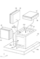
図1および図2に示すように、多軸物理量検出装置100は、四角形の板状でありX−Y平面と平行に位置している金属ベース板10と、金属ベース板10のZ(+)側の面である受面10aに配置されている6面体形状の金属ブロック(保持部集合体)30と、金属ブロック30の金属ベース板10と反対側である上面に位置するブロック面30aおよびブロック面30aと隣り合う側面に位置するブロック面30bおよびブロック面30cの3面にそれぞれ配置されている物理量検出センサー40と、物理量検出センサー40のそれぞれに設けられ物理量検出センサー40を駆動するための発振回路基板50と、金属ベース板10に設けられ金属ブロック30、物理量検出センサー40および発振回路基板50を覆っている装置カバー60と、を備えている。なお、物理量検出センサー40は、図3を参照して詳述するパッケージベース411およびリッド(蓋体)412を有し、パッケージベース411の側に発振回路基板50が配置されている。
As shown in FIGS. 1 and 2, the multi-axis physical
また、物理量検出センサー40が配置されるブロック面30aには、X(+)軸方向の端部にY軸に沿って設けられZ(+)軸方向へ突起している凸部31と、Y(−)軸方向の端部にX軸に沿って設けられZ(+)軸方向へ突起している凸部32と、が形成されている。同様に、ブロック面30bには、X(+)軸方向の端部にZ軸に沿って設けられY(+)軸方向へ突起している凸部33が形成されていて、ブロック面30cには、Y(−)軸方向の端部にZ軸に沿って設けられX(−)軸方向へ突起している凸部34が形成されている。この場合、金属ブロック30は、凸部31,32,33,34を含め一体で形成されている。
Further, on the
そして、凸部31は、ブロック面30aと直交する側壁部31aを有し、凸部32は、ブロック面30aと直交する側壁部32aを有している。ブロック面30aに配置される物理量検出センサー40は、リッド412がブロック面30aと側壁部31aと側壁部32aとに接続した状態で固定されている。同様に、凸部33は、ブロック面30bと直交する側壁部33aを有し、ブロック面30bに配置される物理量検出センサー40は、リッド412がブロック面30bと側壁部33aと金属ベース板10の受面10aとに接続した状態で固定されている。凸部34は、ブロック面30cと直交する側壁部34aを有し、ブロック面30cに配置される物理量検出センサー40は、リッド412がブロック面30cと側壁部34aと金属ベース板10の受面10aとに接続した状態で固定されている。この場合、金属ベース板10の受面10aは、側壁部31a,32a,33a,34aに準じる機能を果たしている。また、多軸物理量検出装置100における金属ブロック30と物理量検出センサー40との固定は、接着剤等による化学的方法やネジ等による機械的方法等によって可能であり、ここでは接着剤を用いている。
And the
このような構成の多軸物理量検出装置100において、ブロック面30a、ブロック面30bおよびブロック面30c、並びに凸部31、凸部32、凸部33および凸部34は、保持部に該当する。また、ブロック面30a,30b,30cは、物理量検出センサー40が配置される底面部に該当し、側壁部31a,32a,33a,34aおよび金属ベース板10の受面10aは、対応する底面部と交わるように配置されている構成となっている。これら金属ブロック30および金属ベース板10は、物理量検出センサー40のそれぞれとの熱の伝達が良好であることが好ましく、多軸物理量検出装置100では、軽量であり加工が容易でもあるアルミニウム(Al)を用いている。
In the multi-axis physical
次に、多軸物理量検出装置100が備えている物理量検出センサー40について、説明する。図3(a)は、物理量検出センサーの構成を示す平面図、図3(b)は、物理量検出センサーの構成を示す断面図である。図3(b)は、図3(a)におけるI−I線に沿う断面を表している。図3では、互いに直交する3つの軸として、図1および図2で用いた座標軸とは異なるx軸、y軸、z軸を図示している。
Next, the physical
物理量検出センサー40は、パッケージ41と、素子ベース体42と、物理量検出素子43とを有している。まず、パッケージ41は、パッケージベース411およびリッド(金属蓋体)412からなっている。パッケージベース411は、平板状であって、平板の端部にx軸方向に沿って設けられ素子ベース体42を固定するための段部413と、平板を貫通している孔および孔を塞ぐための封止材からなる封止部414と、を有し、段部413と反対側の面には、発振回路基板50と接続するための外部端子460が形成されている。このパッケージベース411は、セラミックグリーンシートを焼成した酸化アルミニウム焼結体で形成されている。酸化アルミニウム焼結体は、パッケージ用として優れているが、加工が難しい。しかし、この場合、パッケージベース411が平板状であるため、容易に形成することができる。なお、パッケージベース411は、水晶、ガラスおよびシリコン等の材料を用いて形成することもできる。
The physical
また、リッド412は、内部側に凹状に形成されている収容部417を有し、パッケージベース411の段部413に固定されている素子ベース体42を覆うように配置されている。このリッド412は、パッケージベース411と同じ材料や、コバール、ステンレス鋼などの金属等を用いることができ、ここでは、熱伝導性の良い金属でリッド412を形成することが好ましいため、コバールを用いている。そして、リッド412は、シームリング416を介して、パッケージベース411に接合されていて、パッケージベース411とリッド412とを接合すると、収容部417を減圧された気密状態に封止することができる。
The
このような物理量検出センサー40において、収容部417の封止は、パッケージベース411とリッド412との接合後、封止部414の孔から収容部417内の空気を抜いて減圧し、孔をロウ材(封止材)で塞ぐ方法で行われている。これにより、素子ベース体42および物理量検出素子43は、減圧されて気密状態の収容部417内に封止される。なお、収容部417の内部は、窒素、ヘリウム、アルゴンなどの不活性ガスが充填されていてもよい。
In such a physical
次に、素子ベース体42は、水晶板からエッチング等で形成された板状であって、x軸方向に延出しパッケージベース411の段部413に接着剤451で固定されている固定部421と、固定部421からy軸方向へ延出している継ぎ手部422と、継ぎ手部422から固定部421と反対方向へ矩形状をなして延出している可動部423と、固定部421の一端から可動部423の外縁に沿って固定部421の他端まで延出している枠部424と、固定部421から可動部423に掛け渡されて固定されている物理量検出素子43と、可動部423に設けられている質量部425(425a,425b,425c,425d)と、を備えている。
Next, the
可動部423は、枠部424および固定部421によって囲まれていて、固定部421に継ぎ手部422を介して接続され、片持ち支持された状態である。継ぎ手部422は、固定部421と可動部423との間に設けられ、固定部421と可動部423とを接続している。継ぎ手部422の厚みは、固定部421や可動部423の厚みよりも薄く形成されていて、可動部423が固定部421に対して変位(回動)する際に中間ヒンジとして機能する。そして、可動部423に設けられている質量部425(425a,425b,425c,425d)は、z軸方向から見た平面視で矩形状であり、質量部425a,425bが可動部423のリッド412側に配置され、物理量検出素子43を中心にした左右対称の位置に接合部452によって固定されている。一方、質量部425c,425dは、可動部423のパッケージベース411側に配置され、質量部425a,425bとそれぞれ重なるように接合部452によって固定されている。
The
次に、物理量検出素子43は、固定部421に接着剤450で固定されている基部431aと、可動部423に接着剤450で固定されている基部431bと、基部431aと基部431bとの間にあって物理量を検出するための振動梁部432(432a,432b)と、を有している。この場合、振動梁部432は、その形状が角柱状であり、振動梁部432a,432bのそれぞれに設けられた励振電極(図示せず)に駆動信号(交流電圧)が印加されると、x軸に沿って、互いに離間または近接するように屈曲振動をする。励振電極は、駆動信号の印加のために、図示しない配線によって外部端子460と電気的に接続されている。
Next, the physical
なお、物理量検出素子43は、この場合、水晶の原石等から所定の角度で切り出された水晶基板を、フォトリソグラフィー技術およびエッチング技術によってパターニングすることにより形成されている。さらに、物理量検出素子43は、素子ベース体42との線膨張係数の差を小さくすることを考慮すれば、素子ベース体42と同質材であることが望ましい。
In this case, the physical
また、多軸物理量検出装置100において、図2に示すように、金属ブロック30のブロック面30aに接続する物理量検出センサー40は、物理量検出素子43がX軸に沿うように配置され、Y軸まわりの加速度等を検出する。そして、金属ブロック30のブロック面30bに接続する物理量検出センサー40は、物理量検出素子43がZ軸に沿うように配置され、X軸まわりの加速度等を検出し、金属ブロック30のブロック面30cに接続する物理量検出センサー40は、物理量検出素子43がY軸に沿うように配置され、Z軸まわりの加速度等を検出する。このような配置により、多軸物理量検出装置100は、多軸の検出センサーとして機能する。
In the multi-axis physical
次に、物理量検出センサー40の動作について説明する。図4(a)(b)は、物理量検出センサーの動作を示す断面図である。図4(a)に示すように、物理量検出センサー40に、例えば、+z方向の矢印α1方向に加速度が印加されると、可動部423には−z方向に力が作用し、可動部423は継ぎ手部422を支点として−z方向に変位する。これにより、物理量検出センサー40には、y軸に沿って基部431aと基部431bとが互いに離れる方向の力が加わり、物理量検出素子43の振動梁部432には引っ張り応力が生じる。そのため、振動梁部432の振動する周波数である共振周波数は高くなる。
Next, the operation of the physical
一方、図4(b)に示すように、物理量検出センサー40に、例えば、−z方向の矢印α2方向に加速度が印加されると、可動部423には+z方向に力が作用し、可動部423は、継ぎ手部422を支点として+z方向に変位する。これにより、物理量検出センサー40には、y軸に沿って基部431aと基部431bとが互いに近づく方向の力が加わり、物理量検出素子43の振動梁部432には圧縮応力が生じる。そのため、振動梁部432の共振周波数は、低くなる。
On the other hand, as shown in FIG. 4B, when an acceleration is applied to the physical
物理量検出センサー40では、上記のような物理量検出素子43の共振周波数の変化を検出している。即ち、物理量検出センサー40に加わる加速度は、上記の検出された共振周波数の変化の割合に応じて、ルックアップテーブルなどによって定められた数値に変換することで導出される。
The physical
なお、物理量検出センサー40は、傾斜計としても用いることができる。傾斜計としての物理量検出センサー40は、傾斜による姿勢の変化に応じて、物理量検出センサー40に対する重力加速度が加わる方向が変化し、振動梁部432に引っ張り応力や圧縮応力が生じる。そして、振動梁部432の共振周波数が変化することになり、傾斜による姿勢の変化が導出される。
The physical
以上説明した多軸物理量検出装置100は、3つの物理量検出センサー40が金属ブロック30の底面部(ブロック面30a,30b,30c)のいずれかに接続していると共に、側壁部31a,32a,33a,34aのいずれかにも接続している。また、金属ブロック30のブロック面30a,30b,30cへの接続は、物理量検出センサー40における熱伝導の良好な金属蓋体であるリッド412の側で行われている。従って、それぞれの物理量検出センサー40は、ブロック面30a,30b,30cにのみ接続している場合に比べて、金属ブロック30との熱伝導性が向上し、いずれかの物理量検出センサー40に温度変化が生じても、当該物理量検出センサー40と金属ブロック30との間の熱伝導により、その温度変化を低減できる。これにより、多軸物理量検出装置100は、物理量検出センサー40それぞれがほぼ均一な温度を保持するため、高精度を維持することができる。加えて、物理量検出センサー40が金属ブロック30のブロック面30a,30b,30cおよび側壁部31a,32a,33a,34aに接続して、広い面積で固定されているため、耐衝撃性の向上も図れる。
(多軸物理量検出装置の製造方法)
In the multi-axis physical
(Manufacturing method of multi-axis physical quantity detection device)
次に、多軸物理量検出装置100の製造法について、説明する。図5は、多軸物理量検出装置の製造方法を示すフローチャートである。まず、工程S1において、金属ブロックおよび物理量検出センサーを用意する。多軸物理量検出装置100の場合、凸部31,32,33,34を有している金属ブロック30と、3つの物理量検出センサー40と、を準備しておく。ここでは、金属ブロック30に金属ベース板10が付属していて、これら金属ベース板10を含む金属ブロック30および物理量検出センサー40は、前工程において、別々に製造されている。なお、金属ブロック30および金属ベース板10の製造において、使用する金属はアルミニウムであるが、150W/mK以上の熱伝導率を有している金属であれば用いることができる。例えば、熱伝導率が約200W/mKのアルミニウムの他、熱伝導率が約370W/mKの銅、熱伝導率が約190W/mKのタングステン、熱伝導率が約420W/mKの銀等が挙げられる。この工程S1は、準備工程に該当する。準備後、工程S2へ進む。
Next, a method for manufacturing the multi-axis physical
工程S2において、金属ブロックの底面部と側壁部とに接着剤を塗布する。この場合、底面部は、金属ブロック30における金属ベース板10の受面10aに配置される面と反対側のブロック面30a、およびブロック面30aと隣り合うブロック面30b,30cであり、これら底面部と、凸部31,32,33,34のそれぞれの側壁部31a,32a,33a,34aと、に接着剤を塗布する。接着剤としては特に規定しないが、ここでは、エポキシ樹脂系の熱硬化型の接着剤を用いている。なお、接着剤の塗布は、底面部と側壁部とに塗布するのが固定強度の観点から好ましいが、底面部または側壁部のいずれか一方であっても良い。また、多軸物理量検出装置100における金属ブロック30と物理量検出センサー40との固定は、ネジ等による方法でも可能であるが、ここでは接着剤を用いた場合を示している。塗布後、工程S3へ進む。
In step S2, an adhesive is applied to the bottom and side walls of the metal block. In this case, the bottom surface portions are the
工程S3において、物理量検出センサーのリッド(蓋体)を金属ブロックに対向させて配置する。物理量検出センサー40において、この場合金属のコバールで形成されているリッド412は、セラミックである酸化アルミニウム焼結体のパッケージベース411に比べて熱伝導性が良好である。そのため、物理量検出センサー40において、物理量検出センサー40と金属ブロック30との熱伝導を促進させるように、リッド412の側を金属ブロック30に向けて配置する。その際、物理量検出センサー40は、図2を参照して既述したように、物理量検出素子43を所定方向に向けた配置とする。この工程S3は、配置工程に該当する。配置後、工程S4へ進む。
In step S3, the lid (lid) of the physical quantity detection sensor is arranged to face the metal block. In the physical
工程S4において、物理量検出センサーを金属ブロックの底面部と側壁部とに接続する。つまり、リッド412の側を金属ブロック30に向けて配置された物理量検出センサー40を、接着剤の塗布されている底面部(ブロック面30a,30b,30c)および側壁部31a,32a,33a,34aに押し付けて、金属ブロック30に接続する。物理量検出センサー40が配置される金属ブロック30には、工程S2で接着剤がすでに塗布されているため、物理量検出センサー40は接着剤で仮固定される。接続後、工程S5に進む。
In step S4, the physical quantity detection sensor is connected to the bottom and side walls of the metal block. In other words, the physical
工程S5において、金属ブロックの3面に物理量検出センサーが接続されたか否かを確認する。この確認は、確認用センサーあるいは作業者によって行われる。金属ブロック30の3面すべてに物理量検出センサー40が接続されていれば、工程S6へ進み、一方、金属ブロックの1面または2面にしか物理量検出センサー40が接続されていなければ、工程S3へ戻る。
In step S5, it is confirmed whether or not a physical quantity detection sensor is connected to the three surfaces of the metal block. This confirmation is performed by a confirmation sensor or an operator. If the physical
物理量検出センサー40の接続がすべて終了していれば、工程S6において、接着剤を加熱して、物理量検出センサーを固定する。ここでは、熱硬化型の接着剤を用いているので、加熱により接着剤を硬化させて、金属ブロック30に物理量検出センサー40を固定している。この工程S6は、工程S4と共に接続工程に該当する。以上で多軸物理量検出装置100の製造法に関するフローが終了する。
(実施形態2)
If all the connections of the physical
(Embodiment 2)
次に、多軸物理量検出装置100における他の好適な例について説明する。図6は、本発明の実施形態2に係る多軸物理量検出装置の構成を示す断面図である。また、図7は、実施形態2に係る多軸物理量検出装置の構成を分解して示す斜視図である。実施形態2の多軸物理量検出装置200は、金属ブロック(保持部集合体)80と物理量検出センサー40との接続構造に特徴があり、特徴部分が実施形態1の多軸物理量検出装置100とは異なっている。従って、実施形態1と異なっている部分以外には実施形態1と同符号を付与して説明する。
Next, another preferred example of the multi-axis physical
図6および図7に示すように、多軸物理量検出装置200は、金属ベース板10と、金属ベース板10の受面10aに配置されている金属ブロック80と、金属ブロック80の金属ベース板10と反対側の上平面および上平面と隣り合う2つの側立面の3面(複数の保持部)にそれぞれ配置されている物理量検出センサー40と、物理量検出センサー40のそれぞれに設けられている発振回路基板50と、装置カバー60と、を備えている。
As shown in FIGS. 6 and 7, the multi-axis physical
また、物理量検出センサー40が配置される上平面には、物理量検出センサー40の平面視での四角形形状(図3(a))と相似形状の開口を有する凹部(保持部)81が形成されている。同様に、一方の側立面には、物理量検出センサー40と相似形状の開口を有する凹部(保持部)82が形成されていて、他方の側立面には、物理量検出センサー40と相似形状の開口を有する凹部(保持部)83が形成されている。この場合、金属ブロック80は、凹部81,82,83を含め一体で形成されている。
In addition, a concave portion (holding portion) 81 having an opening similar to a quadrangular shape (FIG. 3A) in plan view of the physical
そして、凹部81は、凹状を形成する底面である底面部81aと、底面部81aと直交している内側面である4つの側壁部81bと、を有している。凹部81に配置される物理量検出センサー40は、リッド412が底面部81aと側壁部81bとに接続した状態で固定されている。同様に、凹部82は、凹状を形成する底面である底面部82aと、底面部82aと直交している内側面である4つの側壁部82bと、を有し、物理量検出センサー40のリッド412が底面部82aと側壁部82bとに接続した状態で固定されている。凹部83は、凹状を形成する底面である底面部83aと、底面部83aと直交している内側面である4つの側壁部83bと、を有し、物理量検出センサー40のリッド412が底面部83aと側壁部83bとに接続した状態で固定されている。
And the recessed
金属ブロック80は、物理量検出センサー40のそれぞれとの熱の伝達が良好であることが好ましく、多軸物理量検出装置200では、軽量で加工が容易でもあるアルミニウム(Al)を用いている。
The
このような構成の多軸物理量検出装置200は、物理量検出センサー40が金属ブロック80の凹部81,82,83内部に配置されている形態である。そのため、物理量検出センサー40は、実施形態1における形態に比べて、金属ブロック80との接触面積が大きくなって熱伝導が行われやすくなり、物理量検出センサー40のそれぞれを、より均一な温度状態に保持することができる。これにより、多軸物理量検出装置200は、3つの物理量検出センサー40が高精度を維持することができ、3つの方向(多軸)の加速度等を正確に検出することができる。
(電子機器)
The multi-axis physical
(Electronics)
次に、多軸物理量検出装置100,200を用いた電子機器について、説明する。図8(a)は、多軸物理量検出装置を備えたビデオカメラを示す斜視図、図8(b)は、多軸物理量検出装置を備えた携帯電話を示す斜視図である。これら電子機器としてのビデオカメラ300および携帯電話400は、本発明に係る多軸物理量検出装置100,200のうち、多軸物理量検出装置100を搭載している。最初に、図8(a)に示すビデオカメラ300は、受像部301と、操作部302と、音声入力部303と、表示ユニット304と、を備えている。このビデオカメラ300は、多軸物理量検出装置100を備えており、3つの物理量検出センサー40が均一な温度状態を保持して、X軸、Y軸、Z軸(不図示)方向の加速度等を検出することにより、手ぶれを補正する機能を発揮できる。これにより、ビデオカメラ300は、鮮明な動画映像を記録することができる。
Next, electronic devices using the multi-axis physical
また、図8(b)に示す携帯電話400は、複数の操作ボタン401と、表示ユニット402と、カメラ機構403と、シャッターボタン404と、を備えていて、電話機およびカメラとして機能する。この携帯電話400は、多軸物理量検出装置100を備えており、3つの物理量検出センサー40が均一な温度状態を保持して、X軸、Y軸、Z軸(不図示)方向の加速度等を検出することにより、カメラ機構403の手ぶれを補正する機能を発揮できる。これにより、携帯電話400は、カメラ機構403により鮮明な画像を記録することができる。
(移動体)
A
(Moving body)
次に、多軸物理量検出装置100,200を用いた移動体について、説明する。図8(c)は、多軸物理量検出装置を備えた移動体を示す斜視図である。図8(c)に示すように、この場合の移動体500は、自動車であって、多軸物理量検出装置100が一例として用いられている。移動体500において、多軸物理量検出装置100は、車体501に搭載されている電子制御ユニット(ECU:electronic control unit)503に内蔵されている。電子制御ユニット503は、多軸物理量検出装置100の3つの物理量検出センサー40が均一な温度状態を保持して、車体501に加えられた加速度等を検出することにより、移動体500の移動状態や姿勢等を把握し、タイヤ502等の制御を的確に行うことができる。これにより、移動体500は、安全で安定した移動をすることが可能である。
Next, a moving body using the multi-axis physical
以上説明した多軸物理量検出装置、多軸物理量検出装置の製造方法、電子機器および移動体は、各実施形態における形態に限定されるものではなく、次に挙げる変形例のような形態であっても、実施形態と同様な効果が得られる。 The multi-axis physical quantity detection device, the manufacturing method of the multi-axis physical quantity detection device, the electronic apparatus, and the moving body described above are not limited to the forms in each embodiment, and are in forms such as the following modifications. Also, the same effect as the embodiment can be obtained.
(変形例1)多軸物理量検出装置100,200は、3つの物理量検出センサー40を備えているが、これに限定されるものではない。例えば、多軸物理量検出装置100,200は、検出すべき物理量に対応して、3つ以外の複数の物理量検出センサー40を備える構成であっても良い。
(Modification 1) Although the multi-axis physical
(変形例2)多軸物理量検出装置100の金属ブロック30は、凸部31,32,33,34を含め一体で形成されているが、これに限定されるものではなく、例えば、金属ブロック30は、凸部31,32,33,34がそれぞれ別体で形成されていて、各凸部31,32,33,34を金属ブロック30の所定位置に固定する構成であっても良い。同様に、金属ブロック80は、凹部81,82,83を含め一体で形成されているが、例えば、金属ブロック80の凹部81において、4つの側壁部81bを有する4角形リングを別体で形成しておき、この4角形リングを金属ブロック80の底面部81aとなる面に固定するような構成等であっても良い。この場合、凹部82,83も同様にして構成される。
(Modification 2) The
(変形例3)物理量検出センサー40は、パッケージ41のパッケージベース411が平板状であり、リッド412が内部側に収容部417を有する凹状であるが、この形態に限定されず、パッケージ41のリッド412が平板状であり、パッケージベース411が内部側に収容部417を有する凹状であっても良い。
(Modification 3) In the physical
(変形例4)多軸物理量検出装置200において、3つの物理量検出センサー40は、凹部81,82,83のいずれかに配置され、それぞれの4つの側壁部に接続して固定されているが、4つの側壁部すべてと接続せずに、例えば3つの側壁部と接続している形態等であっても良い。さらに、多軸物理量検出装置200において、凹部81,82,83は、4つの面をそれぞれ有する側壁部81b,82b,83bがいずれかの面を欠いた形態等であっても良い。この場合、物理量検出センサー40は、側壁部81b,82b,83bの例えば3つの面に接続することになる。但し、熱伝達の観点からは、実施形態2に示すように、物理量検出センサー40が側壁部81b,82b,83bの4つの面に接続している形態が好ましい。
(Modification 4) In the multi-axis physical
(変形例5)多軸物理量検出装置100,200は、既述した加速度計および傾斜計として機能する物理量検出センサー40だけでなく、振動センサー、重力センサーおよび角速度センサー等を備えることもできる。いずれのセンサーを複数搭載した場合でも、多軸物理量検出装置100,200は、均一な温度状態を保持することができ、センサー機能を最大限に発揮できる。
(Modification 5) The multi-axis physical
10…金属ベース板、30…保持部集合体としての金属ブロック、30a,30b,30c…保持部および底面部としてのブロック面、31…保持部としての凸部、31a…側壁部、32…保持部としての凸部、32a…側壁部、33…保持部としての凸部、33a…側壁部、34…保持部としての凸部、34a…側壁部、40…物理量検出センサー、41…パッケージ、42…素子ベース体、43…物理量検出素子、80…金属ブロック、81…凹部、81a…底面部、81b…側壁部、82…凹部、82a…底面部、82b…側壁部、83…凹部、83a…底面部、83b…側壁部、100…多軸物理量検出装置、200…多軸物理量検出装置、300…電子機器としてのビデオカメラ、400…電子機器としての携帯電話、411…パッケージベース、412…金属蓋体としてのリッド、500…移動体。
DESCRIPTION OF
Claims (8)
前記物理量検出センサーを保持している複数の保持部を有している保持部集合体と、を備え、
前記保持部は、底面部、および前記底面部と交わるように配置されている側壁部を有し、前記物理量検出センサーは前記底面部と前記側壁部とに当接している、ことを特徴とする多軸物理量検出装置。 A plurality of physical quantity detection sensors;
A holding unit assembly having a plurality of holding units holding the physical quantity detection sensor,
The holding portion includes a bottom surface portion and a side wall portion arranged to intersect the bottom surface portion, and the physical quantity detection sensor is in contact with the bottom surface portion and the side wall portion. Multi-axis physical quantity detector.
前記複数の物理量検出センサーを前記蓋体側が前記底面部に向くように配置する配置工程と、
前記複数の物理量検出センサーを前記底面部と前記側壁部とに当接するように接続する接続工程と、
を含むことを特徴とする多軸物理量検出装置の製造方法。 A plurality of holding portions having a bottom surface portion and a side wall portion disposed so as to intersect the bottom surface portion, a holding portion aggregate including metal, and a plurality of physical quantity detection sensors including a lid including metal; A preparation process to prepare,
An arrangement step of arranging the plurality of physical quantity detection sensors so that the lid side faces the bottom surface portion;
A connection step of connecting the plurality of physical quantity detection sensors so as to contact the bottom surface portion and the side wall portion;
The manufacturing method of the multi-axis physical quantity detection apparatus characterized by including.
Priority Applications (1)
| Application Number | Priority Date | Filing Date | Title |
|---|---|---|---|
| JP2012276553A JP2014119412A (en) | 2012-12-19 | 2012-12-19 | Multi-axis physical quantity detection apparatus, manufacturing method of multi-axis physical quantity detection apparatus, electronic apparatus and moving body |
Applications Claiming Priority (1)
| Application Number | Priority Date | Filing Date | Title |
|---|---|---|---|
| JP2012276553A JP2014119412A (en) | 2012-12-19 | 2012-12-19 | Multi-axis physical quantity detection apparatus, manufacturing method of multi-axis physical quantity detection apparatus, electronic apparatus and moving body |
Publications (2)
| Publication Number | Publication Date |
|---|---|
| JP2014119412A true JP2014119412A (en) | 2014-06-30 |
| JP2014119412A5 JP2014119412A5 (en) | 2015-12-17 |
Family
ID=51174356
Family Applications (1)
| Application Number | Title | Priority Date | Filing Date |
|---|---|---|---|
| JP2012276553A Withdrawn JP2014119412A (en) | 2012-12-19 | 2012-12-19 | Multi-axis physical quantity detection apparatus, manufacturing method of multi-axis physical quantity detection apparatus, electronic apparatus and moving body |
Country Status (1)
| Country | Link |
|---|---|
| JP (1) | JP2014119412A (en) |
Cited By (4)
| Publication number | Priority date | Publication date | Assignee | Title |
|---|---|---|---|---|
| JP2017526919A (en) * | 2014-08-26 | 2017-09-14 | ザ ユニバーシティー コート オブ ザ ユニバーシティー オブ グラスゴー | Acceleration measurement |
| JP2018132311A (en) * | 2017-02-13 | 2018-08-23 | セイコーエプソン株式会社 | Physical quantity detection device and electronic device |
| JP2018132349A (en) * | 2017-02-14 | 2018-08-23 | セイコーエプソン株式会社 | Physical amount detector and physical amount detection device |
| US11073532B2 (en) | 2018-03-09 | 2021-07-27 | Seiko Epson Corporation | Sensor module, inclinometer, and structural health monitoring |
Citations (3)
| Publication number | Priority date | Publication date | Assignee | Title |
|---|---|---|---|---|
| US5012316A (en) * | 1989-03-28 | 1991-04-30 | Cardiac Pacemakers, Inc. | Multiaxial transducer interconnection apparatus |
| JP2007040766A (en) * | 2005-08-01 | 2007-02-15 | Toyota Motor Corp | Sensor unit |
| US7291023B1 (en) * | 2006-11-21 | 2007-11-06 | Autoliv Asp, Inc. | Electric vehicle motion sensor |
-
2012
- 2012-12-19 JP JP2012276553A patent/JP2014119412A/en not_active Withdrawn
Patent Citations (3)
| Publication number | Priority date | Publication date | Assignee | Title |
|---|---|---|---|---|
| US5012316A (en) * | 1989-03-28 | 1991-04-30 | Cardiac Pacemakers, Inc. | Multiaxial transducer interconnection apparatus |
| JP2007040766A (en) * | 2005-08-01 | 2007-02-15 | Toyota Motor Corp | Sensor unit |
| US7291023B1 (en) * | 2006-11-21 | 2007-11-06 | Autoliv Asp, Inc. | Electric vehicle motion sensor |
Cited By (6)
| Publication number | Priority date | Publication date | Assignee | Title |
|---|---|---|---|---|
| JP2017526919A (en) * | 2014-08-26 | 2017-09-14 | ザ ユニバーシティー コート オブ ザ ユニバーシティー オブ グラスゴー | Acceleration measurement |
| US10802042B2 (en) | 2014-08-26 | 2020-10-13 | The University Court Of The University Of Glasgow | Measurement of acceleration |
| JP2018132311A (en) * | 2017-02-13 | 2018-08-23 | セイコーエプソン株式会社 | Physical quantity detection device and electronic device |
| US10718641B2 (en) | 2017-02-13 | 2020-07-21 | Seiko Epson Corporation | Physical quantity measurement device and electronic apparatus |
| JP2018132349A (en) * | 2017-02-14 | 2018-08-23 | セイコーエプソン株式会社 | Physical amount detector and physical amount detection device |
| US11073532B2 (en) | 2018-03-09 | 2021-07-27 | Seiko Epson Corporation | Sensor module, inclinometer, and structural health monitoring |
Similar Documents
| Publication | Publication Date | Title |
|---|---|---|
| JP5655501B2 (en) | Vibration element, vibrator, and electronic device | |
| US10866260B2 (en) | Physical quantity sensor, electronic apparatus, and vehicle | |
| JP2014092531A (en) | Physical quantity detection device, electronic equipment and mobile body | |
| US11204244B2 (en) | Sensor unit and structural health monitoring | |
| US20130167669A1 (en) | Physical quantity detector and electronic apparatus | |
| JP2014119412A (en) | Multi-axis physical quantity detection apparatus, manufacturing method of multi-axis physical quantity detection apparatus, electronic apparatus and moving body | |
| JP2006214898A (en) | Piezo-electric device and electronic equipment | |
| CN108427010B (en) | Physical quantity detection device and electronic equipment | |
| JP5712755B2 (en) | Acceleration detector, acceleration detection device, and electronic apparatus | |
| JP2007192587A (en) | Wiring board for dynamic quantity sensor, manufacturing method of the wiring board for dynamic quantity sensor, and dynamic quantity sensor | |
| JP6866672B2 (en) | Physical quantity detector and physical quantity detector | |
| CN112729268B (en) | Inertial measurement device, electronic apparatus, and moving object | |
| JP2016017792A (en) | Sensor module and electronic apparatus | |
| JP5838694B2 (en) | Physical quantity detector, physical quantity detection device, and electronic apparatus | |
| JP2022044165A (en) | Inertial sensor and inertial measurement device | |
| JP5987500B2 (en) | Physical quantity detection device, electronic device, mobile object | |
| JP6089753B2 (en) | Manufacturing method of physical quantity detection sensor, physical quantity detection sensor, physical quantity detection device, electronic apparatus, and moving body | |
| US11802889B2 (en) | Inertial sensor and inertial measurement device | |
| JP5983142B2 (en) | Manufacturing method of physical quantity detector, physical quantity detector, electronic apparatus and moving body | |
| JP2014098565A (en) | Electronic device, method of manufacturing electronic device, electronic apparatus, and moving body | |
| US20240159534A1 (en) | Electronic Device | |
| JP2013024828A (en) | Physical quantity detector, physical quantity detection device, electronic apparatus and manufacturing method of physical quantity detector | |
| US20240072765A1 (en) | Structure, physical quantity sensor, inertial sensor, and method for manufacturing structure | |
| JP7552377B2 (en) | Sensor Module | |
| JP2014119369A (en) | Physical quantity detection sensor, physical quantity detection device, electronic apparatus, and movable body |
Legal Events
| Date | Code | Title | Description |
|---|---|---|---|
| RD04 | Notification of resignation of power of attorney |
Free format text: JAPANESE INTERMEDIATE CODE: A7424 Effective date: 20150109 |
|
| A521 | Request for written amendment filed |
Free format text: JAPANESE INTERMEDIATE CODE: A523 Effective date: 20151030 |
|
| A621 | Written request for application examination |
Free format text: JAPANESE INTERMEDIATE CODE: A621 Effective date: 20151030 |
|
| RD04 | Notification of resignation of power of attorney |
Free format text: JAPANESE INTERMEDIATE CODE: A7424 Effective date: 20160610 |
|
| RD03 | Notification of appointment of power of attorney |
Free format text: JAPANESE INTERMEDIATE CODE: A7423 Effective date: 20160624 |
|
| A977 | Report on retrieval |
Free format text: JAPANESE INTERMEDIATE CODE: A971007 Effective date: 20160824 |
|
| A131 | Notification of reasons for refusal |
Free format text: JAPANESE INTERMEDIATE CODE: A131 Effective date: 20160830 |
|
| A521 | Request for written amendment filed |
Free format text: JAPANESE INTERMEDIATE CODE: A523 Effective date: 20161025 |
|
| A131 | Notification of reasons for refusal |
Free format text: JAPANESE INTERMEDIATE CODE: A131 Effective date: 20161115 |
|
| A761 | Written withdrawal of application |
Free format text: JAPANESE INTERMEDIATE CODE: A761 Effective date: 20161216 |