JP2014117828A - Image recording device - Google Patents

Image recording device Download PDF

Info

Publication number
JP2014117828A
JP2014117828A JP2012272794A JP2012272794A JP2014117828A JP 2014117828 A JP2014117828 A JP 2014117828A JP 2012272794 A JP2012272794 A JP 2012272794A JP 2012272794 A JP2012272794 A JP 2012272794A JP 2014117828 A JP2014117828 A JP 2014117828A
Authority
JP
Japan
Prior art keywords
gear
transport
conveyance
state
rotation
Prior art date
Legal status (The legal status is an assumption and is not a legal conclusion. Google has not performed a legal analysis and makes no representation as to the accuracy of the status listed.)
Granted
Application number
JP2012272794A
Other languages
Japanese (ja)
Other versions
JP5915512B2 (en
Inventor
Shota Iijima
章太 飯島
Current Assignee (The listed assignees may be inaccurate. Google has not performed a legal analysis and makes no representation or warranty as to the accuracy of the list.)
Brother Industries Ltd
Original Assignee
Brother Industries Ltd
Priority date (The priority date is an assumption and is not a legal conclusion. Google has not performed a legal analysis and makes no representation as to the accuracy of the date listed.)
Filing date
Publication date
Application filed by Brother Industries Ltd filed Critical Brother Industries Ltd
Priority to JP2012272794A priority Critical patent/JP5915512B2/en
Publication of JP2014117828A publication Critical patent/JP2014117828A/en
Application granted granted Critical
Publication of JP5915512B2 publication Critical patent/JP5915512B2/en
Active legal-status Critical Current
Anticipated expiration legal-status Critical

Links

Images

Landscapes

  • Separation, Sorting, Adjustment, Or Bending Of Sheets To Be Conveyed (AREA)
  • Ink Jet (AREA)
  • Handling Of Sheets (AREA)

Abstract

PROBLEM TO BE SOLVED: To provide an image recording device capable of easily adjusting a sheet transport amount.SOLUTION: An image recording device comprises a drive transmission unit that can change a state to a first state in which paired inversion rollers are rotated inversely and paired re-transport rollers are rotated normally, a second state in which paired transport rollers, the paired inversion rollers, and paired the re-transport rollers are rotated normally, and a third state in which the paired transport rollers and the paired inversion rollers are rotated normally, and transmission of a drive force to the paired re-transport rollers is released. If a tip end of the sheet reaches the paired transport rollers (S16: yes) and it is determined that the sheet is held between the paired inversion rollers (S17: No), a first switching process for changing the state of the drive transmission unit from the first state to the second state is executed (S18). If it is determined that a rear end of the sheet passes through the paired inversion rollers (S20: Yes), a second switching process for changing the state of the drive transmission unit from the second state to the third state is executed (S21) before the rear end of the sheet reaches the paired re-transport rollers.

Description

本発明は、シートの両面に画像記録を行うことができる画像記録装置に関する。   The present invention relates to an image recording apparatus capable of recording an image on both sides of a sheet.

特許文献1には、シートの両面に画像記録を行うことのできる画像記録装置が開示されている。より具体的には、特許文献1に記載されている画像記録装置は、第1搬送路上のシートを記録部に向かう第1搬送向きに搬送するPFローラ対と、記録部によって表面に画像記録されたシートを第1向きに搬送するか或いは反転させて第2搬送路に搬送するSBローラ対と、第2搬送路上のシートをPFローラ対に向かう第2搬送向きに搬送させるDXローラ対とを備えている。   Patent Document 1 discloses an image recording apparatus that can perform image recording on both sides of a sheet. More specifically, in the image recording apparatus described in Patent Document 1, an image is recorded on the surface by a pair of PF rollers that convey a sheet on a first conveyance path in a first conveyance direction toward a recording unit, and a recording unit. A pair of SB rollers that convey the sheet in the first direction or reverse and convey it to the second conveyance path, and a pair of DX rollers that convey the sheet on the second conveyance path in the second conveyance direction toward the PF roller pair. I have.

ここで、PFローラ対とSBローラ対とは、同一方向に回転するように構成されている。より具体的には、PFローラ対によってシートを第1搬送向きに搬送しようとする場合、PFローラ対及びSBローラ対は、シートを第1搬送向きに搬送する向きの回転である順回転する。一方、SBローラ対によってシートを第2搬送路に搬送しようとする場合、PFローラ対及びSBローラ対は、順回転とは逆向きの回転である逆回転する。   Here, the PF roller pair and the SB roller pair are configured to rotate in the same direction. More specifically, when a sheet is to be conveyed in the first conveyance direction by the PF roller pair, the PF roller pair and the SB roller pair rotate in the forward direction, which is rotation in a direction in which the sheet is conveyed in the first conveyance direction. On the other hand, when the sheet is to be conveyed to the second conveyance path by the SB roller pair, the PF roller pair and the SB roller pair rotate in the reverse direction, which is a rotation opposite to the forward rotation.

その結果、サイズの大きなシートを第2搬送路で反転させようとすると、PFローラ対とSBローラ対との間でシートの引っ張り合いが生じることになる。ここで、DXローラ対の単位時間当たりの搬送量がPFローラ対より小さいと、PFローラ対とSBローラ対との引っ張り合いによってシートが搬送路の内側に張り付くことがある。そこで、このような課題を解決するために、DXローラ対の単位時間当たりの搬送量をPFローラ対より大きくすることが考えられる。   As a result, when a large sheet is reversed in the second conveyance path, the sheet is pulled between the PF roller pair and the SB roller pair. Here, if the conveyance amount per unit time of the DX roller pair is smaller than the PF roller pair, the sheet may stick to the inside of the conveyance path due to the tension between the PF roller pair and the SB roller pair. Therefore, in order to solve such a problem, it is conceivable to make the conveyance amount per unit time of the DX roller pair larger than that of the PF roller pair.

特開2012−1332号公報JP 2012-1332 A

しかしながら、DXローラ対の単位時間当たりの搬送量を大きくし過ぎると、PFローラ対とDXローラ対との間でシートに撓みを生じる。その結果、DXローラ対を通過したシートの後端がDXローラ対に衝突して、当該シートにシワが発生する可能性がある。このように、PFローラ対及びDXローラ対の単位時間当たりの搬送量が異なることにより、第2搬送路を搬送されるシートに不具合を生じる可能性がある。しかしながら、PFローラ対及びDXローラ対の単位時間当たりの搬送量を完全に一致させるのは困難である。   However, if the conveyance amount per unit time of the DX roller pair is excessively increased, the sheet is bent between the PF roller pair and the DX roller pair. As a result, the trailing edge of the sheet that has passed through the DX roller pair may collide with the DX roller pair, and the sheet may be wrinkled. As described above, when the conveyance amounts per unit time of the PF roller pair and the DX roller pair are different, a problem may occur in the sheet conveyed through the second conveyance path. However, it is difficult to completely match the conveyance amounts per unit time of the PF roller pair and the DX roller pair.

本発明は、上記の事情に鑑みてなされたものであり、その目的は、シートの搬送量の調整が行い易い画像記録装置を提供することにある。   The present invention has been made in view of the above circumstances, and an object of the present invention is to provide an image recording apparatus that can easily adjust the conveyance amount of a sheet.

(1) 本発明の一形態に係る画像記録装置は、シートが第1搬送向きに搬送される第1搬送路と、分岐位置において上記第1搬送路から分岐し且つ上記分岐位置より上記第1搬送向きの上流側の合流位置において上記第1搬送路に合流しており、上記分岐位置から上記合流位置に向かう第2搬送向きにシートが搬送される第2搬送路とが形成された本体と、上記合流位置より上記第1搬送向きの下流側において上記第1搬送路に設けられており、上記第1搬送路上のシートを上記第1搬送向きに搬送する順回転、及び順回転と逆向きの逆回転が可能な搬送ローラ対と、上記搬送ローラ対より上記第1搬送向きの下流側で且つ上記分岐位置より上記第1搬送向きの上流側において上記第1搬送路に設けられており、上記搬送ローラ対によって搬送されたシートに画像記録を行う記録部と、上記分岐位置より上記第1搬送向きの下流側において上記第1搬送路に設けられており、上記記録部によって画像が記録されたシートを、上記第1搬送向きに搬送する順回転、及び上記第1搬送向きの上流側の端部を先端として上記第2搬送路へ搬送する逆回転が可能な反転ローラ対と、上記第2搬送路に設けられており、上記反転ローラ対によって上記第2搬送路に搬送されたシートを上記第2搬送向きに搬送する順回転が可能な再搬送ローラ対と、1以上のモータを含む駆動源と上記駆動源の駆動力を伝達する伝達機構とで構成されており、上記反転ローラ対を逆回転させ且つ上記再搬送ローラ対を順回転させる第1状態と、上記搬送ローラ対及び上記反転ローラ対を順回転させ且つ上記再搬送ローラ対を順回転させる第2状態と、上記搬送ローラ対及び上記反転ローラ対を順回転させ且つ上記再搬送ローラ対への上記駆動源の駆動力の伝達を解除する第3状態と、に状態変化が可能な駆動伝達部と、制御部とを備える。そして、上記制御部は、シートの位置を判断する判断処理と、上記駆動伝達部が上記第1状態であり、上記第2搬送路を通過したシートの先端が上記搬送ローラ対に到達し且つ当該シートが上記反転ローラ対に挟持されていると上記判断処理において判断された場合に、上記駆動伝達部を上記第1状態から上記第2状態に状態変化させる第1切替処理と、上記駆動伝達部が上記第2状態であり、シートの後端が上記反転ローラ対を通過したと上記判断処理において判断された場合に、当該シートの後端が上記再搬送ローラ対に到達するまでの間に、上記駆動伝達部を上記第2状態から上記第3状態に状態変化させる第2切替処理とを実行する。   (1) An image recording apparatus according to an aspect of the present invention includes a first conveyance path in which a sheet is conveyed in a first conveyance direction, a branch position that branches from the first conveyance path, and the first position from the branch position. A main body formed with a second conveyance path that merges with the first conveyance path at the upstream merging position in the conveyance direction and that conveys the sheet in the second conveyance direction from the branch position toward the merging position; A forward rotation that is provided in the first conveyance path downstream from the merging position in the first conveyance direction, and that forwards the sheet on the first conveyance path in the first conveyance direction, and reverse to the forward rotation. A pair of transport rollers capable of reverse rotation, and provided in the first transport path downstream of the transport roller pair in the first transport direction and upstream of the branch position in the first transport direction, Transported by the transport roller pair A recording unit that records an image on the sheet, and a sheet that is provided in the first conveyance path downstream from the branch position in the first conveyance direction, and on which the image is recorded by the recording unit. A reversing roller pair capable of forward rotation for transporting in one transport direction and reverse rotation for transporting to the second transport path with the upstream end in the first transport direction as a tip, and a pair of reverse rollers provided in the second transport path. And a re-conveying roller pair capable of forward rotation for conveying the sheet conveyed to the second conveying path by the reversing roller pair in the second conveying direction, a driving source including one or more motors, and the driving source A first mechanism in which the reverse roller pair is reversely rotated and the re-conveying roller pair is forwardly rotated, and the conveying roller pair and the reverse roller pair are forwardly rotated. And re-feed A second state in which the roller pair is forwardly rotated, and a third state in which the transport roller pair and the reverse roller pair are forwardly rotated and the transmission of the driving force of the driving source to the re-conveying roller pair is released. A drive transmission unit capable of changing the state and a control unit are provided. The control unit determines the position of the sheet, the drive transmission unit is in the first state, the leading edge of the sheet that has passed through the second conveyance path reaches the conveyance roller pair, and the control unit A first switching process for changing the state of the drive transmission unit from the first state to the second state when it is determined in the determination process that the sheet is sandwiched between the pair of reverse rollers; and the drive transmission unit Is the second state, and when it is determined in the determination process that the trailing edge of the sheet has passed the reversing roller pair, until the trailing edge of the sheet reaches the re-conveying roller pair, A second switching process for changing the state of the drive transmission unit from the second state to the third state is executed.

上記構成によれば、シートの後端が反転ローラ対を通過し且つ再搬送ローラ対を通過するまでの期間に再搬送ローラ対への駆動力の伝達を解除することにより、搬送ローラ対及び再搬送ローラ対の単位時間当たりの搬送量が異なることに起因する不具合を抑制できる。なお、「再搬送ローラ対への駆動源の駆動力の伝達を解除」とは、駆動源と再搬送ローラ対との間において駆動力を非伝達状態とすることのみならず、駆動源を停止させること等も含むものとする。   According to the above configuration, the transfer of the driving force to the re-conveying roller pair is canceled during the period until the trailing edge of the sheet passes the reversing roller pair and the re-conveying roller pair. Problems caused by the difference in the conveyance amount per unit time of the conveyance roller pair can be suppressed. “Release the transmission of the driving force of the driving source to the re-conveying roller pair” means not only that the driving force is not transmitted between the driving source and the re-conveying roller pair, but also the driving source is stopped Etc. are included.

(2) 好ましくは、上記駆動源は、正転及び逆転が可能な搬送用モータを含む。上記伝達機構は、上記搬送用モータの正転及び逆転の一方によって上記搬送ローラ対及び上記反転ローラ対を順回転させ、上記搬送用モータの正転及び逆転の他方によって上記搬送ローラ対及び上記反転ローラ対を逆回転させる第1伝達機構と、上記搬送用モータの正転及び逆転の一方を互いに噛合する奇数個のギヤで伝達し、且つ上記搬送用モータの正転及び逆転の他方を偶数個のギヤで伝達することによって、上記再搬送ローラ対を順回転させる第2伝達機構とを有している。そして、上記制御部は、上記第1切替処理において上記搬送用モータの回転を正転及び逆転の他方から一方に切り換えることによって、上記駆動伝達部を上記第1状態から上記第2状態に状態変化させる。   (2) Preferably, the drive source includes a conveyance motor capable of normal rotation and reverse rotation. The transmission mechanism forwardly rotates the transport roller pair and the reverse roller pair by one of forward rotation and reverse rotation of the transport motor, and the transport roller pair and the reverse by the other of forward rotation and reverse rotation of the transport motor. The first transmission mechanism that reversely rotates the roller pair and one of the forward rotation and the reverse rotation of the conveying motor are transmitted by an odd number of gears engaged with each other, and the other of the forward rotation and the reverse rotation of the conveying motor is an even number. And a second transmission mechanism that forwardly rotates the re-conveying roller pair. The control unit changes the state of the drive transmission unit from the first state to the second state by switching the rotation of the conveyance motor from one of forward rotation and reverse rotation to the other in the first switching process. Let

上記構成によれば、モータの回転向きを切り換える制御のみで、第1状態から第2状態への切替を行うことができる。なお、搬送用モータの正転及び逆転と、搬送ローラ対及び反転ローラ対の順回転及び逆回転と、第2伝達機構において駆動力の伝達に用いられるギヤの数(奇数個及び偶数個)との組み合わせを限定する趣旨ではない。すなわち、上述の「搬送用モータの正転及び逆転の一方(他方)」は、第1伝達機構と第2伝達機構とで同一の向きを表すものではなく、搬送ローラ対及び反転ローラ対の回転向きと、第2伝達機構におけるギヤの数とが、それぞれ搬送用モータの回転向きを切り替えることによって切換可能であることを示しているに過ぎない。   According to the above configuration, the switching from the first state to the second state can be performed only by the control for switching the rotation direction of the motor. Note that the forward and reverse rotations of the transport motor, the forward and reverse rotations of the transport roller pair and the reverse roller pair, and the number of gears (odd number and even number) used for transmitting the driving force in the second transmission mechanism, It is not intended to limit the combination. That is, the above-mentioned “one of the forward rotation and reverse rotation of the conveyance motor (the other)” does not represent the same direction in the first transmission mechanism and the second transmission mechanism, but the rotation of the conveyance roller pair and the reverse roller pair. It only shows that the direction and the number of gears in the second transmission mechanism can be switched by switching the rotation direction of the conveying motor.

(3) より具体的には、上記第2伝達機構は、隣接する第1ギヤ及び第2ギヤを含む複数のギヤが互いに噛合されており、上記再搬送ローラ対の駆動軸を回転させるギヤ列と、上記搬送用モータの正転によって第1向きに回転し、上記搬送用モータの逆転によって上記第1向きと逆向きの第2向きに回転する太陽ギヤと、一端側が上記太陽ギヤに対して回動可能に支持された第1アーム及び第2アームと、上記第1アームの他端側に回転可能に支持され且つ上記太陽ギヤに噛合されており、上記太陽ギヤの上記第1向きの回転によって上記太陽ギヤの周りを上記第1向きに公転して上記第1ギヤに噛合され、上記太陽ギヤの上記第2向きの回転によって上記太陽ギヤの周りを上記第2向きに公転して上記第1ギヤから離間される第1振子ギヤと、上記第2アームの他端側に回転可能に支持され且つ上記太陽ギヤに噛合されており、上記太陽ギヤの上記第2向きの回転によって上記太陽ギヤの周りを上記第2向きに公転して上記第2ギヤに噛合され、上記太陽ギヤの上記第1向きの回転によって上記太陽ギヤの周りを上記第1向きに公転して上記第2ギヤから離間される第2振子ギヤと有している。   (3) More specifically, the second transmission mechanism includes a gear train in which a plurality of gears including the adjacent first gear and second gear are meshed with each other, and the drive shaft of the re-conveying roller pair is rotated. And a sun gear that rotates in the first direction by forward rotation of the transport motor, and rotates in a second direction opposite to the first direction by reverse rotation of the transport motor, and one end side with respect to the sun gear A first arm and a second arm that are rotatably supported, and rotatably supported on the other end of the first arm and meshed with the sun gear, and the sun gear rotates in the first direction. To revolve around the sun gear in the first direction and mesh with the first gear, and by rotating the sun gear in the second direction, revolve around the sun gear in the second direction. A first pendulum gear spaced from one gear; The second arm is rotatably supported on the other end side and meshed with the sun gear, and the sun gear revolves around the sun gear in the second direction by the rotation of the sun gear in the second direction. A second pendulum gear is engaged with the second gear, revolves around the sun gear in the first direction by the rotation of the sun gear in the first direction, and is separated from the second gear.

(4) 好ましくは、上記伝達機構は、上記搬送用モータの回転を、上記再搬送ローラ対に伝達する伝達状態と、上記再搬送ローラ対に伝達しない非伝達状態とに状態変化が可能な切替部を更に有している。そして、上記制御部は、上記第2切替処理において、上記搬送用モータを正転及び逆転の他方に回転させた状態で、上記切替部を上記伝達状態から上記非伝達状態に状態変化させることによって、上記伝達機構を上記第2状態から上記第3状態に状態変化させる。   (4) Preferably, the transmission mechanism is capable of changing a state between a transmission state in which the rotation of the conveyance motor is transmitted to the re-conveying roller pair and a non-transmission state in which the rotation is not transmitted to the re-conveying roller pair. It further has a part. In the second switching process, the control unit changes the state of the switching unit from the transmission state to the non-transmission state in a state where the conveyance motor is rotated in the forward rotation or the reverse rotation. The state of the transmission mechanism is changed from the second state to the third state.

(5) より具体的には、上記記録部は、上記第1搬送向きに直交する走査方向に移動可能なキャリッジと、上記キャリッジに搭載され、上記第1搬送路を搬送されるシートにノズルからインクを吐出する記録ヘッドとを有している。上記切替部は、上記走査方向に離間した第1位置及び第2位置に移動可能であり、上記搬送用モータによって駆動される駆動ギヤと、上記第1位置の上記駆動ギヤと噛合されず且つ上記第2位置の上記駆動ギヤと噛合される位置に設けられており、上記駆動ギヤの回転を上記再搬送ローラ対に伝達する被駆動ギヤと、上記駆動ギヤの側面に当接されると共に上記キャリッジの移動経路内に露出されており、上記キャリッジに当接されることによって上記駆動ギヤを上記第2位置から上記第1位置に移動させる切替レバーとを有している。そして、上記制御部は、上記第2切替処理において上記切替レバーに当接される位置に上記キャリッジを移動させることによって、上記切替部を、上記駆動ギヤが上記第2位置に位置する上記伝達状態から、上記駆動ギヤが上記第1位置に位置する上記非伝達状態に状態変化させる。   (5) More specifically, the recording unit includes a carriage that is movable in a scanning direction orthogonal to the first conveyance direction, and a nozzle that is mounted on the carriage and is conveyed to the sheet conveyed through the first conveyance path. And a recording head for discharging ink. The switching unit is movable to a first position and a second position separated in the scanning direction, is not engaged with the driving gear driven by the conveying motor, and the driving gear at the first position, and A driven gear that is provided at a position that meshes with the driving gear in the second position, and that is in contact with a side surface of the driving gear and a driven gear that transmits the rotation of the driving gear to the re-conveying roller pair, and the carriage And a switching lever that moves the drive gear from the second position to the first position by being in contact with the carriage. And the said control part moves the said carriage to the position contact | abutted to the said switching lever in the said 2nd switching process, The said transmission part is the said transmission state in which the said drive gear is located in the said 2nd position Then, the drive gear changes its state to the non-transmission state located at the first position.

上記構成によれば、切替部の状態を切り換えるための駆動源(モータ)を別途設ける必要がなくなるので、モータの数を削減できる。   According to the above configuration, there is no need to separately provide a drive source (motor) for switching the state of the switching unit, so the number of motors can be reduced.

(6) 好ましくは、上記制御部は、シートに対して上記第1搬送向きに沿う所定の幅単位で上記記録部に間欠的に画像記録を行わせる記録処理を繰り返し実行し、且つ上記記録処理の合間に上記第2切替処理を実行する。   (6) Preferably, the control unit repeatedly executes a recording process for causing the recording unit to perform image recording intermittently in a predetermined width unit along the first conveyance direction with respect to the sheet, and the recording process. The second switching process is executed between the intervals.

上記構成によれば、画像記録のスループットを低下させることなく、切替部の状態を切り換えることができる。   According to the above configuration, it is possible to switch the state of the switching unit without reducing the throughput of image recording.

(7) 好ましくは、上記制御部は、シートの後端が上記反転ローラ対を通過したと上記判断処理において判断された場合に、当該シートの後端が上記再搬送ローラ対に到達するまでの間に、上記第2切替処理を繰り返し実行する。   (7) Preferably, when the determination unit determines that the trailing edge of the sheet has passed the reversing roller pair, the control unit waits until the trailing edge of the sheet reaches the re-conveying roller pair. In the meantime, the second switching process is repeatedly executed.

上記構成によれば、切替部の状態を確実に切り換えることができる。   According to the said structure, the state of a switching part can be switched reliably.

(8) 好ましくは、上記制御部は、シートの後端が上記反転ローラ対と上記再搬送ローラ対との間に位置していると上記判断処理において判断された状態で当該シートへの画像記録が終了した場合に、上記第2切替処理を実行した後で上記搬送用モータに正転駆動及び逆転駆動を交互に少なくとも1回実行させる。   (8) Preferably, the control unit records an image on the sheet in a state in which it is determined in the determination process that the trailing edge of the sheet is located between the reversing roller pair and the re-conveying roller pair. Is completed, after the second switching process is executed, the conveyance motor is caused to alternately perform forward rotation driving and reverse rotation driving at least once.

上記構成によれば、切替部の状態をより確実に切り換えることができる。   According to the said structure, the state of a switching part can be switched more reliably.

(9) 好ましくは、上記再搬送ローラ対は、上記搬送用モータによって駆動される駆動ローラと、上記駆動ローラに当接されて回転する従動ローラと、一端側において上記駆動ローラを回転可能に支持し、上記一端側より上記第2搬送向きの上流側に位置する他端側が上記本体に対して回動可能に支持されて上記駆動ローラを上記従動ローラに接離させるアームとを有する。   (9) Preferably, the pair of re-conveying rollers includes a driving roller driven by the conveying motor, a driven roller rotating in contact with the driving roller, and rotatably supporting the driving roller on one end side. The other end side located upstream from the one end side in the second transport direction is rotatably supported with respect to the main body, and has an arm that contacts and separates the driving roller from the driven roller.

上記構成によれば、第2状態において反転ローラがシートを引っ張る力に抗して、当該シートを第2搬送向きに搬送することができる。   According to the above configuration, the sheet can be conveyed in the second conveyance direction against the force of the reverse roller pulling the sheet in the second state.

(10) 一例として、当該画像記録装置は、上記第1搬送路に配置されており、当該位置におけるシートの有無に応じた検知信号を出力する出力部と、上記搬送用モータの回転量を示すパルス信号を出力するロータリーエンコーダとをさらに備える。そして上記制御部は、上記判断処理において、上記ロータリーエンコーダから取得するパルス信号の数を、上記出力部から検知信号を取得した時点からカウントすることによって、当該シートの位置を判断する。   (10) As an example, the image recording apparatus is disposed in the first conveyance path, and outputs an output unit that outputs a detection signal according to the presence or absence of a sheet at the position, and the rotation amount of the conveyance motor. And a rotary encoder that outputs a pulse signal. In the determination process, the control unit determines the position of the sheet by counting the number of pulse signals acquired from the rotary encoder from the time when the detection signal is acquired from the output unit.

(11) 好ましくは、上記再搬送ローラ対は、上記搬送ローラ対よりも単位時間当たりの搬送量が大きい。   (11) Preferably, the re-conveying roller pair has a larger conveying amount per unit time than the conveying roller pair.

これにより、搬送ローラ対と反転ローラ対とがシートを引っ張り合うことによって、シートが搬送路の内側に張り付くことを防止できる。   As a result, the sheet can be prevented from sticking to the inside of the conveyance path when the conveyance roller pair and the reverse roller pair pull each other.

本発明によれば、シートの後端が再搬送ローラ対を通過するまでに再搬送ローラ対を連れ廻り状態にするので、反転されたシートを適切な搬送量で搬送することができる画像記録装置を得ることができる。   According to the present invention, the re-conveying roller pair is rotated until the trailing edge of the sheet passes the re-conveying roller pair, so that the image recording apparatus capable of conveying the inverted sheet with an appropriate conveyance amount. Can be obtained.

図1は、複合機10の斜視図である。FIG. 1 is a perspective view of the multifunction machine 10. 図2は、プリンタ部11の内部構造を模式的に示す縦断面図である。FIG. 2 is a longitudinal sectional view schematically showing the internal structure of the printer unit 11. 図3は、プリンタ部11の内部構造を示す斜視図である。FIG. 3 is a perspective view showing the internal structure of the printer unit 11. 図4は、プリンタ部11の内部構造を示す斜視図である。FIG. 4 is a perspective view showing the internal structure of the printer unit 11. 図5は、プリンタ部11の内部構造を示す平面図である。FIG. 5 is a plan view showing the internal structure of the printer unit 11. 図6は、駆動伝達機構50のローラとベルトとギヤとプーリの伝達関係を示した模式図である。FIG. 6 is a schematic diagram showing the transmission relationship between the roller, belt, gear, and pulley of the drive transmission mechanism 50. 図7(A)は、切替ギヤ51が第1位置のときの各ギヤ51、75、78、88の噛合を模式的に示す平面図であり、図7(B)は、切替ギヤ51が第2位置のときの各ギヤ51、75、78、88の噛合を模式的に示す平面図である。FIG. 7A is a plan view schematically showing the meshing of the respective gears 51, 75, 78, 88 when the switching gear 51 is in the first position, and FIG. It is a top view which shows typically meshing | engagement of each gear 51, 75, 78, 88 at the time of 2 positions. 図8は、切替ギヤ51の位置に対する給送ローラ25及び各搬送ローラ60、62、45、68による記録用紙12の回転向きを説明するための表である。FIG. 8 is a table for explaining the rotation direction of the recording paper 12 by the feeding roller 25 and the conveying rollers 60, 62, 45, 68 with respect to the position of the switching gear 51. 図9は、制御部130の構成を示すブロック図である。FIG. 9 is a block diagram illustrating a configuration of the control unit 130. 図10は、制御部130によって実行される処理の手順を示すフローチャートである。FIG. 10 is a flowchart illustrating a procedure of processing executed by the control unit 130.

以下、適宜図面を参照して本発明の実施形態について説明する。なお、以下に説明される実施形態は本発明の一例にすぎず、本発明の要旨を変更しない範囲で、本発明の実施形態を適宜変更できることは言うまでもない。複合機10は、図1に示す状態に設置されて使用される。本実施形態において、複合機10が使用可能に設置された状態(図1の状態)を基準として上下方向7が定義され、開口13が形成された側を手前側(正面)として前後方向8が定義され、複合機10を手前側から見て左右方向9が定義される。図1に示す3つの方向は、他の図面においても同様に表示される。   Hereinafter, embodiments of the present invention will be described with reference to the drawings as appropriate. The embodiment described below is merely an example of the present invention, and it is needless to say that the embodiment of the present invention can be changed as appropriate without departing from the gist of the present invention. The multifunction machine 10 is installed and used in the state shown in FIG. In the present embodiment, the vertical direction 7 is defined with reference to a state in which the multifunction machine 10 is installed (the state shown in FIG. 1), and the front-rear direction 8 is defined as the front side (front side) where the opening 13 is formed. The left-right direction 9 is defined when the multifunction machine 10 is viewed from the front side. The three directions shown in FIG. 1 are similarly displayed in other drawings.

[複合機10の全体構造]
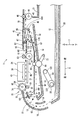
図1に示されるように、複合機10(本発明の画像記録装置の一例)は、下部にプリンタ部11を備えている。複合機10は、ファクシミリ機能及びプリント機能などの各種の機能を有している。プリント機能としては、記録用紙12(本発明のシートの一例、図2参照)の両面に画像を記録する両面画像記録機能を有している。プリンタ部11は、正面に開口13が形成されている。記録用紙12を載置可能な給送トレイ20(図2参照)及び排出トレイ21(図2参照)が、開口13から前後方向8に挿抜可能である。なお、複合機10によって画像記録されるのは記録用紙12に限定されない。例えば、複合機10は、CDやDVDのレーベル面に画像記録してもよい。この場合、CDやDVDは、薄板状のメディアトレイに載置されて、開口13などから複合機10内に挿入される。
[Overall structure of MFP 10]
As shown in FIG. 1, the multifunction machine 10 (an example of the image recording apparatus of the present invention) includes a printer unit 11 at the bottom. The multifunction machine 10 has various functions such as a facsimile function and a print function. As a print function, it has a double-sided image recording function for recording images on both sides of the recording paper 12 (an example of the sheet of the present invention, see FIG. 2). The printer unit 11 has an opening 13 formed in the front. A feed tray 20 (see FIG. 2) and a discharge tray 21 (see FIG. 2) on which the recording paper 12 can be placed can be inserted and removed in the front-rear direction 8 from the opening 13. Note that image recording by the multifunction machine 10 is not limited to the recording paper 12. For example, the multifunction machine 10 may record an image on the label surface of a CD or DVD. In this case, the CD or DVD is placed on a thin plate-shaped media tray and inserted into the multifunction machine 10 through the opening 13 or the like.

図2に示されるように、給送トレイ20の上側に給送ローラ25が設けられている。給送ローラ25は、給送トレイ20に載置された記録用紙12の上面に当接可能に設けられている。給送ローラ25は、搬送用モータ71(図3〜図5参照)の逆転駆動力を付与されて順回転する。なお、給送ローラ25の順回転とは、記録用紙12を第1搬送路65に送り出し、且つ第1搬送路65上を第1搬送向き15に搬送する向きの回転である。すなわち、プリンタ部11を図2の方向から見た給送ローラ25の順回転は、時計回りの回転である。   As shown in FIG. 2, a feeding roller 25 is provided on the upper side of the feeding tray 20. The feeding roller 25 is provided so as to be in contact with the upper surface of the recording paper 12 placed on the feeding tray 20. The feed roller 25 is rotated forward by the reverse driving force of the conveying motor 71 (see FIGS. 3 to 5). The forward rotation of the feeding roller 25 is a rotation in a direction in which the recording paper 12 is sent to the first transport path 65 and transported on the first transport path 65 in the first transport direction 15. That is, the forward rotation of the feeding roller 25 when the printer unit 11 is viewed from the direction of FIG. 2 is a clockwise rotation.

プリンタ部11(本発明の本体の一例)の内部には、給送トレイ20の後端部から第1搬送路65が延出されている。第1搬送路65は、湾曲部と直線部とを備える。第1搬送路65は、所定間隔を隔てて互いに対向する外側ガイド部材18と内側ガイド部材19とによって区画されている。給送トレイ20に収容された記録用紙12は、湾曲部を下方から上方へUターンするように搬送された後、直線部を搬送されて記録部24に搬送される。記録部24により画像記録が行われた記録用紙12は、直線部を搬送されて排出トレイ21に排出される。つまり、記録用紙12は、図2に一点鎖線の矢印で示される第1搬送向き15に搬送される。   A first transport path 65 extends from the rear end of the feed tray 20 inside the printer unit 11 (an example of the main body of the present invention). The first transport path 65 includes a curved portion and a straight portion. The first transport path 65 is partitioned by an outer guide member 18 and an inner guide member 19 that face each other with a predetermined interval. The recording paper 12 accommodated in the feeding tray 20 is conveyed so as to make a U-turn from the lower side to the upper side of the curved portion, and then conveyed along the straight portion and conveyed to the recording unit 24. The recording paper 12 on which image recording has been performed by the recording unit 24 is conveyed through the linear portion and discharged to the discharge tray 21. That is, the recording paper 12 is transported in the first transport direction 15 indicated by a one-dot chain line arrow in FIG.

また、プリンタ部11の内部には、第2搬送路67が設けられている。第2搬送路67は、分岐位置36において第1搬送路65から分岐し、分岐位置36より第1搬送向き15の上流側の合流位置37において第1搬送路65と合流するように延びた経路である。つまり、第2搬送路67は、分岐位置36及び合流位置37において第1搬送路65と接続されている。第2搬送路67は、上下方向7において対向するガイド部材31、32によって区画されている。分岐位置36においてスイッチバックされた記録用紙12は、第2搬送路67を分岐位置36から合流位置37に向かう第2搬送向き16(図2に二点鎖線の矢印で示される向き)に搬送され、再び第1搬送路65に導かれる。   A second transport path 67 is provided inside the printer unit 11. The second conveyance path 67 branches from the first conveyance path 65 at the branch position 36 and extends so as to merge with the first conveyance path 65 at the merge position 37 upstream of the first conveyance direction 15 from the branch position 36. It is. That is, the second transport path 67 is connected to the first transport path 65 at the branch position 36 and the merge position 37. The second transport path 67 is partitioned by guide members 31 and 32 that face each other in the vertical direction 7. The recording paper 12 switched back at the branch position 36 is transported through the second transport path 67 in the second transport direction 16 (direction indicated by the two-dot chain line arrow in FIG. 2) from the branch position 36 to the merge position 37. Then, it is guided again to the first transport path 65.

[搬送ローラ対、排出ローラ対、反転ローラ対、再搬送ローラ対]
図2に示されるように、第1搬送路65には、記録部24よりも第1搬送向き15の上流側において第1搬送ローラ60及びピンチローラ61を備える搬送ローラ対と、記録部24よりも第1搬送向き15の下流側において第2搬送ローラ62及び拍車63を備える排出ローラ対と、第2搬送ローラ62よりも第1搬送向き15の下流側において第3搬送ローラ45及び拍車46を備える反転ローラ対と、が設けられている。また、第2搬送路67には、第4搬送ローラ68、従動ローラ69、及びアーム70(図3〜図5では、図示省略)を備える再搬送ローラ対が設けられている。各ローラ対は、記録用紙12を挟持した状態で回転することによって、記録用紙12を搬送する。
[Conveying roller pair, discharge roller pair, reverse roller pair, re-conveying roller pair]
As shown in FIG. 2, the first conveyance path 65 includes a conveyance roller pair including a first conveyance roller 60 and a pinch roller 61 on the upstream side in the first conveyance direction 15 from the recording unit 24, and a recording unit 24. The discharge roller pair including the second conveyance roller 62 and the spur 63 on the downstream side in the first conveyance direction 15, and the third conveyance roller 45 and the spur 46 on the downstream side in the first conveyance direction 15 from the second conveyance roller 62. A reversing roller pair provided is provided. Further, the second transport path 67 is provided with a re-transport roller pair including a fourth transport roller 68, a driven roller 69, and an arm 70 (not shown in FIGS. 3 to 5). Each roller pair conveys the recording paper 12 by rotating with the recording paper 12 sandwiched therebetween.

搬送ローラ対は、第1搬送向き15において、合流位置37より下流側で且つ記録部24より上流側に設けられている。本実施形態における第1搬送ローラ60は、第1搬送路65の上側に配置されており、第1搬送路65を搬送される記録用紙12の記録面(記録部24によって画像が記録される面)に当接する。第1搬送ローラ60は、正転駆動及び逆転駆動が可能な搬送用モータ71から駆動力が付与されて回転する軸34に外嵌されており、軸34と一体回転する。一方、ピンチローラ61は、第1搬送路65の下側において第1搬送ローラ60に対向して配置されている。ピンチローラ61は、第1搬送ローラ60の回転に伴って連れ回る。第1搬送ローラ60とピンチローラ61とは、協同して記録用紙12を挟持し、第1搬送向き15に搬送する。   The pair of transport rollers is provided on the downstream side from the joining position 37 and on the upstream side from the recording unit 24 in the first transport direction 15. The first transport roller 60 in the present embodiment is disposed above the first transport path 65, and the recording surface of the recording paper 12 transported through the first transport path 65 (the surface on which an image is recorded by the recording unit 24). ). The first transport roller 60 is externally fitted to a rotating shaft 34 to which a driving force is applied from a transport motor 71 capable of forward rotation and reverse rotation, and rotates integrally with the shaft 34. On the other hand, the pinch roller 61 is disposed below the first conveyance path 65 so as to face the first conveyance roller 60. The pinch roller 61 rotates with the rotation of the first transport roller 60. The first conveyance roller 60 and the pinch roller 61 cooperate to sandwich the recording paper 12 and convey it in the first conveyance direction 15.

第1搬送ローラ60は、正転駆動する搬送用モータ71から駆動力を付与されて順回転する。ここで、第1搬送ローラ60の順回転とは、記録用紙12を第1搬送向き15に搬送する向きの回転である。すなわち、プリンタ部11を図2の方向から見た第1搬送ローラ60の順回転は反時計回りの回転であり、ピンチローラ61の順回転は時計回りの回転である。以下、「搬送ローラ対の順回転」と表記したときは、図2に示される第1搬送ローラ60が反時計回りに回転し、且つピンチローラ61が時計回りに回転することを指す。   The first transport roller 60 is rotated forward by a driving force applied from a transport motor 71 that is normally driven. Here, the forward rotation of the first transport roller 60 is a rotation in the direction in which the recording paper 12 is transported in the first transport direction 15. That is, when the printer unit 11 is viewed from the direction of FIG. 2, the forward rotation of the first conveying roller 60 is a counterclockwise rotation, and the forward rotation of the pinch roller 61 is a clockwise rotation. Hereinafter, the expression “forward rotation of the conveyance roller pair” means that the first conveyance roller 60 shown in FIG. 2 rotates counterclockwise and the pinch roller 61 rotates clockwise.

一方、第1搬送ローラ60は、逆転駆動する搬送用モータ71から駆動力を付与されて逆回転する。第1搬送ローラ60の逆回転とは、記録用紙12を第1搬送向き15とは逆向きに搬送する向きの回転である。すなわち、図2の方向から見た第1搬送ローラ60の逆回転は時計回りの回転であり、ピンチローラ61の逆回転は反時計回りの回転である。以下、「搬送ローラ対の逆回転」と表記したときは、図2に示される第1搬送ローラ60が時計回りに回転し、且つピンチローラ61が反時計回りに回転することを指す。   On the other hand, the first transport roller 60 rotates in the reverse direction by being applied with a driving force from a transport motor 71 that is driven in reverse. The reverse rotation of the first transport roller 60 is a rotation in the direction in which the recording paper 12 is transported in the direction opposite to the first transport direction 15. That is, the reverse rotation of the first conveying roller 60 viewed from the direction of FIG. 2 is a clockwise rotation, and the reverse rotation of the pinch roller 61 is a counterclockwise rotation. Hereinafter, the expression “reverse rotation of the conveying roller pair” means that the first conveying roller 60 shown in FIG. 2 rotates clockwise and the pinch roller 61 rotates counterclockwise.

排出ローラ対は、第1搬送向き15において、記録部24より下流側で且つ分岐位置36より上流側に設けられている。本実施形態における第2搬送ローラ62は、第1搬送路65の下側に配置されており、第1搬送路65を搬送される記録用紙12の記録面の裏面に当接する。第2搬送ローラ62は、搬送用モータ71から駆動力が付与されて回転する軸64に外嵌されており、軸64と一体回転する。一方、拍車63は、第1搬送路65の上側において第2搬送ローラ62に対向して配置されている。拍車63は、第2搬送ローラ62の回転に伴って連れ回る。第2搬送ローラ62と拍車63とは、協同して記録用紙12を挟持し、第1搬送向き15に搬送する。   The discharge roller pair is provided downstream of the recording unit 24 and upstream of the branch position 36 in the first transport direction 15. The second transport roller 62 in the present embodiment is disposed below the first transport path 65 and abuts on the back surface of the recording surface of the recording paper 12 transported through the first transport path 65. The second transport roller 62 is fitted around a shaft 64 that is rotated by a driving force applied from the transport motor 71, and rotates integrally with the shaft 64. On the other hand, the spur 63 is disposed on the upper side of the first conveyance path 65 so as to face the second conveyance roller 62. The spur 63 rotates with the rotation of the second transport roller 62. The second conveyance roller 62 and the spur 63 cooperate to sandwich the recording paper 12 and convey it in the first conveyance direction 15.

第2搬送ローラ62は、正転駆動する搬送用モータ71から駆動力を付与されて順回転する。ここで、第2搬送ローラ62の順回転とは、記録用紙12を第1搬送向き15に搬送する向きの回転である。すなわち、図2の方向から見た第2搬送ローラ62の順回転は時計回りの回転であり、拍車63の順回転は反時計回りの回転である。以下、「排出ローラ対の順回転」と表記したときは、図2に示される第2搬送ローラ62が時計回りに回転し、且つ拍車63が反時計回りに回転することを指す。   The second transport roller 62 is rotated forward by a driving force applied from a transport motor 71 that is normally driven. Here, the forward rotation of the second transport roller 62 is a rotation in the direction in which the recording paper 12 is transported in the first transport direction 15. That is, the forward rotation of the second transport roller 62 viewed from the direction of FIG. 2 is a clockwise rotation, and the forward rotation of the spur 63 is a counterclockwise rotation. Hereinafter, the expression “forward rotation of the discharge roller pair” means that the second transport roller 62 shown in FIG. 2 rotates clockwise and the spur 63 rotates counterclockwise.

一方、第2搬送ローラ62は、逆転駆動する搬送用モータ71から駆動力を付与されて逆回転する。第2搬送ローラ62の逆回転とは、記録用紙12を第1搬送向き15とは逆向きに搬送する向きの回転である。すなわち、図2の方向から見た第2搬送ローラ62の逆回転は反時計回りの回転であり、拍車63の逆回転は時計回りの回転である。以下、「排出ローラ対の逆回転」と表記したときは、図2に示される第2搬送ローラ62が反時計回りに回転し、且つ拍車63が時計回りに回転することを指す。   On the other hand, the second transport roller 62 rotates in the reverse direction by being applied with a driving force from a transport motor 71 that is driven in reverse. The reverse rotation of the second transport roller 62 is a rotation in the direction in which the recording paper 12 is transported in the direction opposite to the first transport direction 15. That is, the reverse rotation of the second transport roller 62 viewed from the direction of FIG. 2 is a counterclockwise rotation, and the reverse rotation of the spur 63 is a clockwise rotation. Hereinafter, the expression “reverse rotation of the discharge roller pair” means that the second transport roller 62 shown in FIG. 2 rotates counterclockwise and the spur 63 rotates clockwise.

反転ローラ対は、分岐位置36より第1搬送向き15の下流側に設けられている。本実施形態における第3搬送ローラ45は、第1搬送路65の下側に配置されており、第1搬送路65を搬送される記録用紙12の記録面の裏面に当接する。第3搬送ローラ45は、搬送用モータ71から駆動力が付与されて回転する軸44に外嵌されており、軸44と一体回転する。一方、拍車46は、第1搬送路65の上側において第3搬送ローラ45に対向して配置されている。拍車46は、第3搬送ローラ45の回転に伴って連れ回る。第3搬送ローラ45と拍車46とは、協同して記録用紙12を挟持し、第1搬送向き15或いは第2搬送路67に搬送する。   The reverse roller pair is provided downstream of the branch position 36 in the first transport direction 15. The third transport roller 45 in the present embodiment is disposed below the first transport path 65 and abuts on the back surface of the recording surface of the recording paper 12 transported through the first transport path 65. The third transport roller 45 is fitted around a shaft 44 that is rotated by a driving force applied from the transport motor 71 and rotates integrally with the shaft 44. On the other hand, the spur 46 is disposed on the upper side of the first conveyance path 65 so as to face the third conveyance roller 45. The spur 46 rotates with the rotation of the third transport roller 45. The third conveyance roller 45 and the spur 46 cooperate to sandwich the recording paper 12 and convey it to the first conveyance direction 15 or the second conveyance path 67.

第3搬送ローラ45は、正転駆動する搬送用モータ71から駆動力を付与されて順回転する。ここで、第3搬送ローラ45の順回転とは、記録用紙12を第1搬送向き15に搬送する向きの回転である。すなわち、図2の方向から見た第3搬送ローラ45の順回転は時計回りの回転であり、拍車46の順回転は反時計回りの回転である。以下、「反転ローラ対の順回転」と表記したときは、図2に示される第3搬送ローラ45が時計回りに回転し、且つ拍車46が反時計回りに回転することを指す。   The third transport roller 45 is rotated forward by a driving force applied from a transport motor 71 that is normally driven. Here, the forward rotation of the third transport roller 45 is rotation in a direction in which the recording paper 12 is transported in the first transport direction 15. That is, the forward rotation of the third conveying roller 45 viewed from the direction of FIG. 2 is a clockwise rotation, and the forward rotation of the spur 46 is a counterclockwise rotation. Hereinafter, the expression “forward rotation of the pair of reverse rollers” indicates that the third transport roller 45 shown in FIG. 2 rotates clockwise and the spur 46 rotates counterclockwise.

一方、第3搬送ローラ45は、逆転駆動する搬送用モータ71から駆動力を付与されて逆回転する。第3搬送ローラ45の逆回転とは、記録用紙12を第1搬送向き15とは逆向きに搬送する向きの回転である。すなわち、図2の方向から見た第3搬送ローラ45の逆回転は反時計回りの回転であり、拍車46の逆回転は時計回りの回転である。以下、「反転ローラ対の逆回転」と表記したときは、図2に示される第3搬送ローラ45が反時計回りに回転し、且つ拍車46が時計回りに回転することを指す。   On the other hand, the third conveyance roller 45 is reversely rotated by being applied with a driving force from a conveyance motor 71 that is reversely driven. The reverse rotation of the third transport roller 45 is a rotation in the direction in which the recording paper 12 is transported in the direction opposite to the first transport direction 15. That is, the reverse rotation of the third transport roller 45 viewed from the direction of FIG. 2 is a counterclockwise rotation, and the reverse rotation of the spur 46 is a clockwise rotation. Hereinafter, the expression “reverse rotation of the reverse roller pair” means that the third transport roller 45 shown in FIG. 2 rotates counterclockwise and the spur 46 rotates clockwise.

再搬送ローラ対は、第2搬送路67に設けられている。本実施形態における第4搬送ローラ68(本発明の駆動ローラの一例)は、第2搬送路67の下側に配置されている。第4搬送ローラ68は、正転駆動及び逆転駆動が可能な搬送用モータ71から駆動力が付与されて回転する。一方、従動ローラ69は、第2搬送路67の上側において第4搬送ローラ68に対向して配置されている。従動ローラ69は、第4搬送ローラ68の回転に伴って連れ回る。第4搬送ローラ68と従動ローラ69とは、協同して記録用紙12を挟持し、第2搬送向き16に搬送する。   The re-transport roller pair is provided in the second transport path 67. The fourth transport roller 68 (an example of the driving roller of the present invention) in the present embodiment is disposed below the second transport path 67. The fourth transport roller 68 is rotated by a driving force applied from a transport motor 71 capable of forward drive and reverse drive. On the other hand, the driven roller 69 is disposed on the upper side of the second conveyance path 67 so as to face the fourth conveyance roller 68. The driven roller 69 rotates with the rotation of the fourth transport roller 68. The fourth transport roller 68 and the driven roller 69 cooperate to sandwich the recording paper 12 and transport it in the second transport direction 16.

図2に示されるように、アーム70は、その一端側において第4搬送ローラ68を回転可能に支持し、他端側がプリンタ部11に対して回動可能に支持されている。また、プリンタ部11に支持されている側の端部は、第4搬送ローラ68を支持している側の端部よりも第2搬送向き16の上流側に配置されている。これにより、アーム70は、第4搬送ローラ68を従動ローラ69に接離させることができる。より詳細には、再搬送ローラ対に挟持された記録用紙12に第2搬送向き16と逆向きの力が付与された際に、アーム70は、第4搬送ローラ68を従動ローラ69に押しつけるように動作する。   As shown in FIG. 2, the arm 70 rotatably supports the fourth transport roller 68 at one end side thereof, and is supported rotatably at the other end side with respect to the printer unit 11. Further, the end portion on the side supported by the printer unit 11 is disposed upstream of the second conveyance direction 16 with respect to the end portion on the side supporting the fourth conveyance roller 68. As a result, the arm 70 can bring the fourth transport roller 68 into and out of contact with the driven roller 69. More specifically, the arm 70 presses the fourth transport roller 68 against the driven roller 69 when a force opposite to the second transport direction 16 is applied to the recording paper 12 sandwiched between the pair of re-transport rollers. To work.

第4搬送ローラ68は、搬送用モータ71の回転向き(正転駆動及び逆転駆動)に拘わらず順回転する。ここで、第4搬送ローラ68の順回転とは、記録用紙12を第2搬送向き16に搬送させる向きの回転である。すなわち、図2の方向から見た第4搬送ローラ68の順回転は反時計回りの回転であり、従動ローラ69の順回転は時計回りの回転である。以下、「再搬送ローラ対の順回転」と表記したときは、図2に示される第4搬送ローラ68が反時計回りに回転し、且つ従動ローラ69が時計回りに回転することを指す。   The fourth conveyance roller 68 rotates forward regardless of the rotation direction (forward rotation drive and reverse rotation drive) of the conveyance motor 71. Here, the forward rotation of the fourth transport roller 68 is a rotation in a direction in which the recording paper 12 is transported in the second transport direction 16. That is, the forward rotation of the fourth transport roller 68 viewed from the direction of FIG. 2 is a counterclockwise rotation, and the forward rotation of the driven roller 69 is a clockwise rotation. Hereinafter, the expression “forward rotation of the re-conveying roller pair” means that the fourth conveying roller 68 shown in FIG. 2 rotates counterclockwise and the driven roller 69 rotates clockwise.

なお、再搬送ローラ対は、搬送ローラ対よりも単位時間当たりの搬送量を大きく設定するのが望ましい。これにより、記録用紙12が搬送路の内側に張り付くことを抑制できる。なお、再搬送ローラ対の単位時間当たりの搬送量を大きくする具体的な方法は特に限定されないが、例えば、第4搬送ローラ68の直径を第1搬送ローラ60の直径より大きくしてもよいし、搬送用モータ71から第4搬送ローラ68までの駆動力の伝達経路における減速比を、搬送用モータ71から第1搬送ローラ60までの駆動力の伝達経路における減速比よりも小さくしてもよい。   The re-conveying roller pair is preferably set to have a larger conveying amount per unit time than the conveying roller pair. Thereby, it can suppress that the recording paper 12 sticks to the inner side of a conveyance path. A specific method for increasing the transport amount per unit time of the re-transport roller pair is not particularly limited. For example, the diameter of the fourth transport roller 68 may be larger than the diameter of the first transport roller 60. The reduction ratio in the transmission path of the driving force from the conveyance motor 71 to the fourth conveyance roller 68 may be smaller than the reduction ratio in the transmission path of the driving force from the conveyance motor 71 to the first conveyance roller 60. .

[記録部24]
図2に示されるように、記録部24は、第1搬送路65において、第1搬送ローラ60の第1搬送向き15の下流側で且つ第2搬送ローラ62の第1搬送向き15の上流側に設けられている。記録部24の下側で且つ第1搬送路65を挟んで記録部24と対向する位置には、プラテン42が設けられている。プラテン42は、第1搬送路65を搬送される記録用紙12を支持する。記録部24は、プラテン42に支持された記録用紙12に公知のインクジェット方式で画像を記録する。記録部24は、記録用紙12にインク滴を吐出する複数のノズルが形成された記録ヘッド38と、記録ヘッド38を搭載するキャリッジ40とを備えている。
[Recording unit 24]
As shown in FIG. 2, in the first conveyance path 65, the recording unit 24 is downstream of the first conveyance roller 60 in the first conveyance direction 15 and upstream of the second conveyance roller 62 in the first conveyance direction 15. Is provided. A platen 42 is provided below the recording unit 24 and at a position facing the recording unit 24 with the first conveyance path 65 interposed therebetween. The platen 42 supports the recording paper 12 conveyed through the first conveyance path 65. The recording unit 24 records an image on the recording paper 12 supported by the platen 42 by a known inkjet method. The recording unit 24 includes a recording head 38 in which a plurality of nozzles that eject ink droplets are formed on the recording paper 12, and a carriage 40 on which the recording head 38 is mounted.

キャリッジ40は、プリンタ部11のフレームなどによって、前後方向8と直交する左右方向9(本発明の走査方向の一例)へ往復動可能に支持されている。キャリッジ40は、公知のベルト機構を介してキャリッジ駆動用モータ53(図9参照)と連結されている。キャリッジ40は、キャリッジ駆動用モータ53から駆動力が伝達されることによって左右方向9に往復動される。プラテン42に記録用紙12が支持されている状態で、キャリッジ40が往復動される。キャリッジ40が往復動されているときに、記録ヘッド38からインク滴が吐出される。これにより、プラテン42に支持された記録用紙12に画像が記録される。   The carriage 40 is supported by the frame of the printer unit 11 so as to be capable of reciprocating in the left-right direction 9 (an example of the scanning direction of the present invention) orthogonal to the front-rear direction 8. The carriage 40 is connected to a carriage driving motor 53 (see FIG. 9) via a known belt mechanism. The carriage 40 is reciprocated in the left-right direction 9 when a driving force is transmitted from the carriage driving motor 53. With the recording paper 12 supported on the platen 42, the carriage 40 is reciprocated. When the carriage 40 is reciprocated, ink droplets are ejected from the recording head 38. As a result, an image is recorded on the recording paper 12 supported by the platen 42.

[第1センサ160及び第2センサ170]
図2に示されるように、第1搬送路65において、第1搬送ローラ60よりも第1搬送向き15の上流側で且つ合流位置37より第1搬送向き15の下流側には、第1センサ160(本発明の出力部の一例)が設けられている。第1センサ160は、軸161と、当該軸161を中心に回動可能な検出子162と、発光素子及び当該発光素子から発光された光を受光する受光素子を有する光学センサ163とを備えている。
[First sensor 160 and second sensor 170]
As shown in FIG. 2, in the first transport path 65, the first sensor is located upstream of the first transport roller 60 in the first transport direction 15 and downstream of the merge position 37 in the first transport direction 15. 160 (an example of the output unit of the present invention) is provided. The first sensor 160 includes a shaft 161, a detector 162 that can rotate around the shaft 161, and an optical sensor 163 that includes a light emitting element and a light receiving element that receives light emitted from the light emitting element. Yes.

検出子162の一端は、第1搬送路65に突出している。検出子162の一端に外力が加えられていないとき、検出子162の他端は光学センサ163の発光素子から受光素子に至る光路に進入して、当該光路を通る光を遮断している。このとき、光学センサ163は、後述する制御部130にローレベル信号(「信号レベルが閾値未満の信号」であって、本発明の第2検知信号の一例である。)を出力する。一方、検出子162の一端が記録用紙12の第1搬送向き15の下流端に押されて回転すると、検出子162の他端は上記光路から外れて、上記光路に光が通る。このとき、光学センサ163は、制御部130にハイレベル信号(「信号レベルが閾値以上の信号」であって、本発明の第1検知信号の一例である。)を出力する。すなわち、第1センサ160は、第1センサ160が設置された位置における記録用紙12の有無に応じた検知信号を、制御部130に出力する。   One end of the detector 162 protrudes into the first conveyance path 65. When an external force is not applied to one end of the detector 162, the other end of the detector 162 enters an optical path from the light emitting element to the light receiving element of the optical sensor 163, and blocks light passing through the optical path. At this time, the optical sensor 163 outputs a low level signal (“signal whose signal level is less than the threshold”, which is an example of the second detection signal of the present invention) to the control unit 130 described later. On the other hand, when one end of the detector 162 is pushed and rotated by the downstream end of the recording paper 12 in the first conveying direction 15, the other end of the detector 162 is removed from the optical path, and light passes through the optical path. At this time, the optical sensor 163 outputs a high level signal (“signal having a signal level equal to or higher than a threshold”, which is an example of the first detection signal of the present invention) to the control unit 130. That is, the first sensor 160 outputs a detection signal corresponding to the presence or absence of the recording paper 12 at the position where the first sensor 160 is installed to the control unit 130.

第1搬送路65において、記録部24及び第2搬送ローラ62より第1搬送向き15の下流側で且つ分岐位置36より第1搬送向き15の上流側には、第2センサ170が設けられている。第2センサ170は、第1センサ160と同様に、軸171と検出子172と光学センサ173とを備えている。第2センサ170は、第1センサ160と同様に、第2センサ170が設置された位置における記録用紙12の有無に応じた検知信号を、制御部130に出力する。   In the first conveyance path 65, a second sensor 170 is provided on the downstream side in the first conveyance direction 15 from the recording unit 24 and the second conveyance roller 62 and on the upstream side in the first conveyance direction 15 from the branch position 36. Yes. Similar to the first sensor 160, the second sensor 170 includes a shaft 171, a detector 172, and an optical sensor 173. Similar to the first sensor 160, the second sensor 170 outputs a detection signal according to the presence or absence of the recording paper 12 at the position where the second sensor 170 is installed to the control unit 130.

[ロータリーエンコーダ73]
図2に示されるように、第1搬送ローラ60には、第1搬送ローラ60の回転によってパルス信号を発生させるロータリーエンコーダ73が設けられている。ロータリーエンコーダ73は、第1搬送ローラ60の軸34に設けられて第1搬送ローラ60と共に回転するエンコーダディスク74と、エンコーダディスク74を厚み方向(図2の紙面において垂直な方向)から挟むように設けられた光学センサ72とからなる。エンコーダディスク74には、光が透過される透過部と光が透過されない非透過部とが円周方向に等ピッチで交互に配置されている。光学センサ72は、エンコーダディスク74に向けて発光部(不図示)から光を照射し、エンコーダディスク74を通過した光を受光部(不図示)で受光する。
[Rotary encoder 73]
As shown in FIG. 2, the first transport roller 60 is provided with a rotary encoder 73 that generates a pulse signal by the rotation of the first transport roller 60. The rotary encoder 73 is provided on the shaft 34 of the first transport roller 60 and rotates with the first transport roller 60 so as to sandwich the encoder disk 74 from the thickness direction (a direction perpendicular to the paper surface of FIG. 2). And an optical sensor 72 provided. In the encoder disk 74, transmissive portions through which light is transmitted and non-transmissive portions through which light is not transmitted are alternately arranged at equal pitches in the circumferential direction. The optical sensor 72 emits light from a light emitting unit (not shown) toward the encoder disk 74, and the light passing through the encoder disk 74 is received by a light receiving unit (not shown).

光学センサ72の発光部とエンコーダディスク74の透過部とが対面するとき、発光部から出力された光は受光部で受光される。このとき、光学センサ72は、ハイレベル信号を制御部130に出力する。一方、光学センサ72の発光部とエンコーダディスク74の非透過部とが対面するとき、発光部から出力された光は受光部で受光されない。このとき、光学センサ72は、ローレベル信号を制御部130に出力する。その結果、エンコーダディスク74が回転(換言すれば、搬送用モータ71或いは第1搬送ローラ60が回転)することによって、光学センサ72から制御部130にパルス信号が出力される。   When the light emitting part of the optical sensor 72 and the transmission part of the encoder disk 74 face each other, the light output from the light emitting part is received by the light receiving part. At this time, the optical sensor 72 outputs a high level signal to the control unit 130. On the other hand, when the light emitting part of the optical sensor 72 and the non-transmissive part of the encoder disk 74 face each other, the light output from the light emitting part is not received by the light receiving part. At this time, the optical sensor 72 outputs a low level signal to the control unit 130. As a result, the encoder disk 74 is rotated (in other words, the conveying motor 71 or the first conveying roller 60 is rotated), whereby a pulse signal is output from the optical sensor 72 to the control unit 130.

[経路切替部材41]
図2に示されるように、第1搬送路65において、第2搬送ローラ62より第1搬送向き15の下流側で且つ第3搬送ローラ45より第1搬送向き15の上流側(すなわち、分岐位置36)には、経路切替部材41が設けられている。経路切替部材41は、補助ローラ47、48と、フラップ49と、軸87とを備えている。フラップ49は、軸87から概ね第1搬送向き15に延出されており、且つ軸87に回動可能に軸支されている。また、拍車状の補助ローラ47、48は、フラップ49に回転可能に軸支されている。フラップ49は、軸87を中心として回動することによって、内側ガイド部材19よりも分岐位置36の上方に位置する排出姿勢(図2に破線で示される姿勢)と、延出端部49Aが分岐位置36の下方に位置する反転姿勢(図2に実線で示される姿勢)とに姿勢変化が可能に構成されている。
[Route switching member 41]
As shown in FIG. 2, in the first conveyance path 65, the second conveyance roller 62 is downstream in the first conveyance direction 15 and the third conveyance roller 45 is upstream in the first conveyance direction 15 (that is, the branch position). 36), a path switching member 41 is provided. The path switching member 41 includes auxiliary rollers 47 and 48, a flap 49, and a shaft 87. The flap 49 extends substantially from the shaft 87 in the first conveying direction 15 and is pivotally supported by the shaft 87 so as to be rotatable. The spur-shaped auxiliary rollers 47 and 48 are rotatably supported by the flap 49. The flap 49 pivots about the shaft 87, so that the discharge posture (the posture indicated by the broken line in FIG. 2) positioned above the branch position 36 relative to the inner guide member 19 and the extended end portion 49A branch. The posture can be changed to a reverse posture (posture indicated by a solid line in FIG. 2) located below the position 36.

通常状態におけるフラップ49は、自重によって反転姿勢である。そして、フラップ49は、第1搬送路65を搬送される記録用紙12に持ち上げられることによって、軸87周りに回動して反転姿勢から排出姿勢に姿勢変化する。以後、フラップ49(詳細には補助ローラ47、48)は、記録用紙12と当接して記録用紙12をガイドする。記録用紙12の第1搬送向き15の上流側の端部(すなわち、後端)が補助ローラ47を通過すると、フラップ49は、自重によって排出姿勢から反転姿勢に姿勢変化する。これにより、記録用紙12の第1搬送向き15の後端が下側(すなわち、第2搬送路67の入り口)を向く。この状態において第3搬送ローラ45が順回転を継続すると、記録用紙12は、第1搬送向き15に搬送されて排出トレイ21に排出される。一方、第3搬送ローラ45の回転が順回転から逆回転に切り換えられると、記録用紙12は、第1搬送向き15の上流側の端部を先端として、第2搬送路67に導かれる。   The flap 49 in the normal state is in an inverted posture due to its own weight. Then, the flap 49 is rotated around the shaft 87 by being lifted by the recording sheet 12 conveyed through the first conveyance path 65, and changes its posture from the reverse posture to the discharge posture. Thereafter, the flaps 49 (specifically, the auxiliary rollers 47 and 48) contact the recording paper 12 and guide the recording paper 12. When the upstream end (that is, the rear end) of the recording paper 12 in the first conveyance direction 15 passes through the auxiliary roller 47, the flap 49 changes its posture from the discharge posture to the reverse posture due to its own weight. Thereby, the rear end of the first conveyance direction 15 of the recording paper 12 faces downward (that is, the entrance of the second conveyance path 67). When the third transport roller 45 continues to rotate forward in this state, the recording paper 12 is transported in the first transport direction 15 and discharged to the discharge tray 21. On the other hand, when the rotation of the third conveyance roller 45 is switched from the forward rotation to the reverse rotation, the recording paper 12 is guided to the second conveyance path 67 with the end on the upstream side in the first conveyance direction 15 as the leading end.

[駆動伝達機構50]
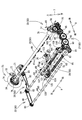
図3〜図5に示されるように、プリンタ部11には、搬送用モータ71の駆動力を各ローラ対に伝達する駆動伝達機構50が設けられている。駆動伝達機構50は、ローラプーリ76と、モータプーリ58と、第1ベルト77と、第1駆動伝達部26と、第2駆動伝達部27と、第3駆動伝達部33と、第4駆動伝達部28と、給送駆動伝達部29と、切替部30とを備えている。搬送用モータ71及び駆動伝達機構50は、本発明の駆動伝達部の一例である。
[Drive transmission mechanism 50]
As shown in FIGS. 3 to 5, the printer unit 11 is provided with a drive transmission mechanism 50 that transmits the driving force of the conveying motor 71 to each roller pair. The drive transmission mechanism 50 includes a roller pulley 76, a motor pulley 58, a first belt 77, a first drive transmission unit 26, a second drive transmission unit 27, a third drive transmission unit 33, and a fourth drive transmission unit 28. A feeding drive transmission unit 29 and a switching unit 30. The conveyance motor 71 and the drive transmission mechanism 50 are examples of the drive transmission unit of the present invention.

図5に示されるように、ローラプーリ76は、第1搬送路65よりも左側において、第1搬送ローラ60の軸34に取り付けられている。図3〜図5に示されるように、搬送用モータ71には、当該搬送用モータ71の回転軸にモータプーリ58が取り付けられている。無端環状の第1ベルト77は、ローラプーリ76とモータプーリ58とに架け渡されている。これにより、搬送用モータ71の回転駆動力は、第1搬送ローラ60に伝達される。具体的には図8に示されるように、第1搬送ローラ60は、搬送用モータ71が正転駆動されると順回転し、搬送用モータ71が駆動逆転されると逆回転する。   As shown in FIG. 5, the roller pulley 76 is attached to the shaft 34 of the first transport roller 60 on the left side of the first transport path 65. As shown in FIGS. 3 to 5, a motor pulley 58 is attached to the rotation shaft of the conveyance motor 71 in the conveyance motor 71. The endless annular first belt 77 is stretched between a roller pulley 76 and a motor pulley 58. Thereby, the rotational driving force of the conveyance motor 71 is transmitted to the first conveyance roller 60. Specifically, as shown in FIG. 8, the first transport roller 60 rotates forward when the transport motor 71 is driven to rotate forward, and rotates reversely when the transport motor 71 is driven reversely.

[第1駆動伝達部26]
図3〜図6に示されるように、第1駆動伝達部26は、左ギヤ52と、下ギヤ80と、第1プーリ81と、第2プーリ82と、第2ベルト83とを備えている。左ギヤ52は、第1搬送ローラ60の軸34において第1搬送路65よりも左側に設けられている。下ギヤ80は、左ギヤ52の下側において左ギヤ52と噛合されている。第1プーリ81は、下ギヤ80の右側に取り付けられており、下ギヤ80と同軸且つ一体に回転する。これにより、第1プーリ81は、第1搬送ローラ60の回転に連動して回転する。第2プーリ82は、第2搬送ローラ62の軸64に取り付けられている。無端環状の第2ベルト83は、第1プーリ81と第2プーリ82とに架け渡されている。
[First drive transmission unit 26]
As shown in FIGS. 3 to 6, the first drive transmission unit 26 includes a left gear 52, a lower gear 80, a first pulley 81, a second pulley 82, and a second belt 83. . The left gear 52 is provided on the left side of the first conveyance path 65 on the shaft 34 of the first conveyance roller 60. The lower gear 80 meshes with the left gear 52 on the lower side of the left gear 52. The first pulley 81 is attached to the right side of the lower gear 80 and rotates coaxially and integrally with the lower gear 80. As a result, the first pulley 81 rotates in conjunction with the rotation of the first transport roller 60. The second pulley 82 is attached to the shaft 64 of the second transport roller 62. The endless second belt 83 is bridged between the first pulley 81 and the second pulley 82.

なお、第2プーリ82の内側には、公知のワンウェイクラッチ(具体的にはニードルクラッチ)が設けられている。つまり、第2プーリ82は、ワンウェイクラッチを介して軸64に取り付けられている。これにより、第1駆動伝達部26は、正転駆動される搬送用モータ71の回転駆動力を第2搬送ローラ62に伝達し、逆転駆動される搬送用モータ71の回転駆動力を第2搬送ローラ62に伝達しない。すなわち、図8に示されるように、第2搬送ローラ62は、第1駆動伝達部26によって伝達された搬送用モータ71の正転駆動力によって順回転する。   A known one-way clutch (specifically, a needle clutch) is provided inside the second pulley 82. That is, the second pulley 82 is attached to the shaft 64 via the one-way clutch. As a result, the first drive transmission unit 26 transmits the rotational driving force of the conveying motor 71 driven in the forward direction to the second conveying roller 62, and the rotational driving force of the conveying motor 71 driven in the reverse rotation is transferred into the second conveying roller. It is not transmitted to the roller 62. That is, as shown in FIG. 8, the second transport roller 62 rotates forward by the forward driving force of the transport motor 71 transmitted by the first drive transmission unit 26.

[第3駆動伝達部33]
図3〜図6に示されるように、第3駆動伝達部33は、第3プーリ84と、第4プーリ85と、第3ベルト86とを備えている。第3プーリ84は、軸64における第2プーリ82の左側に取り付けられており、第2プーリ82と同軸且つ一体に回転する。第4プーリ85は、第3搬送ローラ45の軸44に取り付けられている。無端環状の第3ベルト86は、第3プーリ84と第4プーリ85とに架け渡されている。これにより、第2搬送ローラ62の回転は、第3ベルト86を介して第3搬送ローラ45に伝達される。すなわち、図8に示されるように、第3搬送ローラ45は、第2搬送ローラ62と同様に、第1駆動伝達部26及び第3駆動伝達部33によって伝達された搬送用モータ71の正転駆動力によって順回転する。
[Third drive transmission unit 33]
As shown in FIGS. 3 to 6, the third drive transmission unit 33 includes a third pulley 84, a fourth pulley 85, and a third belt 86. The third pulley 84 is attached to the left side of the second pulley 82 on the shaft 64 and rotates coaxially and integrally with the second pulley 82. The fourth pulley 85 is attached to the shaft 44 of the third transport roller 45. The endless annular third belt 86 is bridged between the third pulley 84 and the fourth pulley 85. Thereby, the rotation of the second conveyance roller 62 is transmitted to the third conveyance roller 45 via the third belt 86. That is, as shown in FIG. 8, the third conveyance roller 45 is rotated in the normal direction of the conveyance motor 71 transmitted by the first drive transmission unit 26 and the third drive transmission unit 33 in the same manner as the second conveyance roller 62. Forward rotation by driving force.

[第2駆動伝達部27]
図3〜図6に示されるように、第2駆動伝達部27は、第1ギヤ78と、第1出力ギヤ75と、相互に噛合された複数の第1中間ギヤ95と、第2ギヤ101と、第1振子ギヤ機構96とで構成される。第1振子ギヤ機構96は、第1中間ギヤ95と噛合する太陽ギヤ97と、太陽ギヤ97の周囲を公転且つ自転する振子ギヤ98と、アーム102とを備えている。
[Second drive transmission unit 27]
As shown in FIGS. 3 to 6, the second drive transmission unit 27 includes a first gear 78, a first output gear 75, a plurality of first intermediate gears 95 meshed with each other, and a second gear 101. And a first pendulum gear mechanism 96. The first pendulum gear mechanism 96 includes a sun gear 97 that meshes with the first intermediate gear 95, a pendulum gear 98 that revolves and rotates around the sun gear 97, and an arm 102.

第1ギヤ78は、第1搬送ローラ60の軸34における第1搬送路65よりも右側に設けられている。第1ギヤ78は、第1搬送ローラ60と同軸に設けられており、第1搬送ローラ60と一体に回転する。つまり、第1搬送ローラ60が回転すると、第1ギヤ78も回転する。第1ギヤ78の回転は、後述する切替部30の切替ギヤ51を介して、第1出力ギヤ75に伝達される。   The first gear 78 is provided on the right side of the first conveyance path 65 in the shaft 34 of the first conveyance roller 60. The first gear 78 is provided coaxially with the first transport roller 60 and rotates integrally with the first transport roller 60. That is, when the first transport roller 60 rotates, the first gear 78 also rotates. The rotation of the first gear 78 is transmitted to the first output gear 75 via a switching gear 51 of the switching unit 30 described later.

第1出力ギヤ75は、切替ギヤ51と、第1中間ギヤ95のうちの駆動力の伝達経路の最上流側に位置するギヤと、後述する第4駆動伝達部28の太陽ギヤ109とに噛合されている。なお、第1出力ギヤ75は、図7(B)に示されるように、第2位置に位置する切替ギヤ51に噛合され、第1ギヤ78の回転駆動力が伝達されて回転する。   The first output gear 75 meshes with the switching gear 51, the gear located on the most upstream side of the driving force transmission path of the first intermediate gear 95, and the sun gear 109 of the fourth drive transmission unit 28 described later. Has been. As shown in FIG. 7B, the first output gear 75 is meshed with the switching gear 51 located at the second position, and the rotational driving force of the first gear 78 is transmitted to rotate.

複数の第1中間ギヤ95は、相互に噛合された状態で概ね前後方向8に並んで配置されている。本実施形態では、第1中間ギヤ95は偶数個配置されている。なお、図6では第1中間ギヤ95が便宜上4個描かれているが、4個に限らないのは言うまでもない。駆動力の伝達経路の最下流側に配置された第1中間ギヤ95は、第1振子ギヤ機構96の太陽ギヤ97と噛合される。以上より、第1ギヤ78の回転駆動力は、第2位置の切替ギヤ51、第1出力ギヤ75、及び複数の第1中間ギヤ95を介して、太陽ギヤ97に伝達される。   The plurality of first intermediate gears 95 are arranged in the front-rear direction 8 in a state of being engaged with each other. In the present embodiment, an even number of first intermediate gears 95 are arranged. In FIG. 6, four first intermediate gears 95 are drawn for convenience, but it goes without saying that the number is not limited to four. The first intermediate gear 95 disposed on the most downstream side of the driving force transmission path meshes with the sun gear 97 of the first pendulum gear mechanism 96. As described above, the rotational driving force of the first gear 78 is transmitted to the sun gear 97 via the second position switching gear 51, the first output gear 75, and the plurality of first intermediate gears 95.

太陽ギヤ97は、プリンタ部11のフレームなどによって回転可能に支持されている。太陽ギヤ97のスラスト面には、アーム102の一端が取り付けられている。これにより、アーム102は、太陽ギヤ97と同軸で回動する。アーム102の他端には、振子ギヤ98が回転可能に支持されている。振子ギヤ98は、太陽ギヤ97と噛合されている。よって、振子ギヤ98は、アーム102に支持されて自転し且つ太陽ギヤ97と噛合しながら太陽ギヤ97の外周を太陽ギヤ97の回転向きに公転する。   The sun gear 97 is rotatably supported by the frame of the printer unit 11 or the like. One end of the arm 102 is attached to the thrust surface of the sun gear 97. As a result, the arm 102 rotates coaxially with the sun gear 97. A pendulum gear 98 is rotatably supported at the other end of the arm 102. The pendulum gear 98 is meshed with the sun gear 97. Accordingly, the pendulum gear 98 rotates while being supported by the arm 102 and revolves around the outer periphery of the sun gear 97 in the rotational direction of the sun gear 97 while meshing with the sun gear 97.

以下、図6を参照しながら、第2駆動伝達部27による駆動伝達が説明される。搬送用モータ71が逆転駆動されると、第1搬送ローラ60及び第1ギヤ78は時計回りに回転する。ここで、第1ギヤ78と太陽ギヤ97との間には、切替ギヤ51、第1出力ギヤ75、及び偶数個の第1中間ギヤ95が互いに噛合されている。すなわち、第1ギヤ78と太陽ギヤ97との間には、偶数個のギヤが互いに噛合されている。このため、第1ギヤ78が時計回りに回転した場合、太陽ギヤ97は反時計回り(矢印99の向き)に回転する。   Hereinafter, the drive transmission by the second drive transmission unit 27 will be described with reference to FIG. When the transport motor 71 is driven in reverse, the first transport roller 60 and the first gear 78 rotate clockwise. Here, between the first gear 78 and the sun gear 97, the switching gear 51, the first output gear 75, and the even number of first intermediate gears 95 are meshed with each other. That is, an even number of gears are engaged with each other between the first gear 78 and the sun gear 97. For this reason, when the 1st gear 78 rotates clockwise, the sun gear 97 rotates counterclockwise (direction of the arrow 99).

太陽ギヤ97が反時計回りに回転すると、振子ギヤ98は、時計回りに自転しつつ太陽ギヤ97の周囲を矢印99の向きに公転し、第2ギヤ101に噛合される。振子ギヤ98に噛合された第2ギヤ101は、反時計回りに回転する。ここで、第2ギヤ101は、第2搬送ローラ62の軸64の右端部に設けられており(図3〜図5参照)、第2搬送ローラ62と一体に回転するギヤである。すなわち、図8に示されるように、第2搬送ローラ62は、切替ギヤ51が第2位置である場合に、第2駆動伝達部27によって伝達された搬送用モータ71が逆転駆動力によって逆回転する。   When the sun gear 97 rotates counterclockwise, the pendulum gear 98 revolves around the sun gear 97 in the direction of the arrow 99 while rotating clockwise, and meshes with the second gear 101. The second gear 101 meshed with the pendulum gear 98 rotates counterclockwise. Here, the second gear 101 is provided at the right end of the shaft 64 of the second transport roller 62 (see FIGS. 3 to 5), and is a gear that rotates integrally with the second transport roller 62. That is, as shown in FIG. 8, when the switching gear 51 is in the second position, the second transport roller 62 rotates the transport motor 71 transmitted by the second drive transmission unit 27 in reverse by the reverse driving force. To do.

また、逆回転する第2搬送ローラ62の回転駆動力は、第3プーリ84、第3ベルト86、及び第4プーリ85を介して、第3搬送ローラ45に伝達される。その結果、図8に示されるように、第3搬送ローラ45は、切替ギヤ51が第2位置である場合に、第2駆動伝達部27及び第3駆動伝達部33によって伝達された搬送用モータ71の逆転駆動力によって逆回転する。   The rotational driving force of the second transport roller 62 that rotates in reverse is transmitted to the third transport roller 45 via the third pulley 84, the third belt 86, and the fourth pulley 85. As a result, as shown in FIG. 8, the third transport roller 45 is configured such that the transport motor transmitted by the second drive transmission unit 27 and the third drive transmission unit 33 when the switching gear 51 is in the second position. Reverse rotation is caused by the reverse driving force of 71.

一方、搬送用モータ71が正転駆動した場合、第1ギヤ78は時計回りに回転する。そして、太陽ギヤ97は、第1ギヤ78の回転駆動力が伝達されて時計回り(矢印100)に回転する。これにより、振子ギヤ98は、反時計回りに自転しつつ太陽ギヤ97の周囲を矢印100の向きに公転し、第2ギヤ101から離間される。そのため、第2駆動伝達部27は、搬送用モータ71の正転駆動力を第2搬送ローラ62及び第3搬送ローラ45に伝達しない。   On the other hand, when the transport motor 71 is driven to rotate forward, the first gear 78 rotates clockwise. The sun gear 97 rotates clockwise (arrow 100) when the rotational driving force of the first gear 78 is transmitted. As a result, the pendulum gear 98 revolves around the sun gear 97 in the direction of the arrow 100 while rotating counterclockwise, and is separated from the second gear 101. For this reason, the second drive transmission unit 27 does not transmit the normal driving force of the conveyance motor 71 to the second conveyance roller 62 and the third conveyance roller 45.

上記構成のローラプーリ76、モータプーリ58、第1ベルト77、第1駆動伝達部26、第2駆動伝達部27、及び第3駆動伝達部33は、搬送用モータ71の正転駆動力を伝達して第1搬送ローラ60、第2搬送ローラ62、第3搬送ローラ45を順回転させ、搬送用モータ71の逆転駆動力を伝達して第1搬送ローラ60、第2搬送ローラ62、第3搬送ローラ45を逆回転させる本発明の第1伝達機構の一例である。   The roller pulley 76, the motor pulley 58, the first belt 77, the first drive transmission unit 26, the second drive transmission unit 27, and the third drive transmission unit 33 configured as described above transmit the normal rotation driving force of the conveyance motor 71. The first conveying roller 60, the second conveying roller 62, and the third conveying roller 45 are rotated forward to transmit the reverse driving force of the conveying motor 71 to transmit the first conveying roller 60, the second conveying roller 62, and the third conveying roller. 4 is an example of a first transmission mechanism of the present invention that reversely rotates 45.

[第4駆動伝達部28]
図3〜図6に示されるように、第4駆動伝達部28(本発明の第2伝達機構の一例)は、第2振子ギヤ機構103と、正転噛合ギヤ104と、逆転噛合ギヤ105と、相互に噛合された複数の第2中間ギヤ106と、第3中間ギヤ107と、第3ギヤ108とで構成される。第2振子ギヤ機構103は、第1出力ギヤ75と噛合する太陽ギヤ109と、太陽ギヤ109の周囲を公転且つ自転する2つの振子ギヤ110、111と、2つのアーム112、113とを備えている。
[Fourth drive transmission unit 28]
As shown in FIGS. 3 to 6, the fourth drive transmission unit 28 (an example of the second transmission mechanism of the present invention) includes a second pendulum gear mechanism 103, a forward meshing gear 104, a reverse meshing gear 105, and the like. The plurality of second intermediate gears 106, the third intermediate gear 107, and the third gear 108 meshed with each other. The second pendulum gear mechanism 103 includes a sun gear 109 that meshes with the first output gear 75, two pendulum gears 110 and 111 that revolve and rotate around the sun gear 109, and two arms 112 and 113. Yes.

太陽ギヤ109は、プリンタ部11のフレームなどによって回転可能に支持されている。太陽ギヤ109は、第2駆動伝達部27の第1出力ギヤ75から駆動伝達されて回転する。より詳細には、図7(B)に示されるように、第2位置の切替ギヤ51と第1出力ギヤ75とが噛合されることによって、第1ギヤ78の回転駆動力が第4駆動伝達部28に伝達される。   The sun gear 109 is rotatably supported by the frame of the printer unit 11 or the like. The sun gear 109 is driven and transmitted from the first output gear 75 of the second drive transmission unit 27 to rotate. More specifically, as shown in FIG. 7B, when the switching gear 51 in the second position and the first output gear 75 are meshed, the rotational driving force of the first gear 78 is transferred to the fourth drive. Is transmitted to the unit 28.

太陽ギヤ109のスラスト面には、アーム112、113の一端が取り付けられている。これにより、アーム112、113は、太陽ギヤ97と同軸で回転する。アーム112の他端には、振子ギヤ110が回転可能に支持されている。アーム113の他端には、振子ギヤ111が回転可能に支持されている。振子ギヤ110、111は、太陽ギヤ109と噛合されている。振子ギヤ110は、アーム112に支持されて自転し且つ太陽ギヤ109と噛合しながら太陽ギヤ109の回転向きに公転する。同様に、振子ギヤ111は、アーム113に支持されて自転し且つ太陽ギヤ109と噛合しながら太陽ギヤ109の回転向きに公転する。   One end of the arms 112 and 113 is attached to the thrust surface of the sun gear 109. Thereby, the arms 112 and 113 rotate coaxially with the sun gear 97. A pendulum gear 110 is rotatably supported on the other end of the arm 112. A pendulum gear 111 is rotatably supported on the other end of the arm 113. The pendulum gears 110 and 111 are meshed with the sun gear 109. The pendulum gear 110 rotates while being supported by the arm 112 and revolves in the rotational direction of the sun gear 109 while meshing with the sun gear 109. Similarly, the pendulum gear 111 rotates while being supported by the arm 113 and revolving in the rotational direction of the sun gear 109 while meshing with the sun gear 109.

振子ギヤ110は、正転噛合ギヤ104(本発明の第1ギヤの一例)と噛合可能である。振子ギヤ111は、逆転噛合ギヤ105(本発明の第2ギヤの一例)と噛合可能である。正転噛合ギヤ104、逆転噛合ギヤ105、及び複数の第2中間ギヤ106は、隣接するギヤ同士が相互に噛合されたギヤ列を構成している。逆転噛合ギヤ105は、正転噛合ギヤ104と噛合されている。正転噛合ギヤ104は、逆転噛合ギヤ105と、第2中間ギヤ106のうちの駆動力の伝達経路の最上流側に配置されたギヤとに噛合されている。すなわち、正転噛合ギヤ104と逆転噛合ギヤ105とは、ギヤ列内において互いに隣接している。   The pendulum gear 110 can mesh with the forward meshing gear 104 (an example of the first gear of the present invention). The pendulum gear 111 can mesh with the reverse meshing gear 105 (an example of the second gear of the present invention). The forward meshing gear 104, the reverse meshing gear 105, and the plurality of second intermediate gears 106 constitute a gear train in which adjacent gears mesh with each other. The reverse meshing gear 105 is meshed with the normal meshing gear 104. The forward meshing gear 104 is meshed with the reverse meshing gear 105 and a gear disposed on the most upstream side of the driving force transmission path of the second intermediate gear 106. That is, the forward meshing gear 104 and the reverse meshing gear 105 are adjacent to each other in the gear train.

第2中間ギヤ106は、相互に噛合された状態で概ね前後方向8に並んで配置されている。本実施形態では、第2中間ギヤ106は偶数個配置されている。なお、図6では第2中間ギヤ106が便宜上4個描かれているが、4個に限らないのは言うまでもない。第3中間ギヤ107は、第2中間ギヤ106のうちの駆動力の伝達経路の最下流側に配置されたギヤと同軸に設けられている。第3中間ギヤ107は、第2中間ギヤ106と同軸の軸79を中心として当該第2中間ギヤ106と一体に回転する。第3中間ギヤ107は、第3ギヤ108と噛合されている。第3ギヤ108は、第4搬送ローラ68と同軸に配置されており、第4搬送ローラ68と一体に回転可能である。   The second intermediate gears 106 are arranged side by side in the front-rear direction 8 in a state of being engaged with each other. In the present embodiment, an even number of second intermediate gears 106 are arranged. In FIG. 6, four second intermediate gears 106 are drawn for convenience, but it is needless to say that the number is not limited to four. The third intermediate gear 107 is provided coaxially with the gear disposed on the most downstream side of the driving force transmission path of the second intermediate gear 106. The third intermediate gear 107 rotates integrally with the second intermediate gear 106 around a shaft 79 coaxial with the second intermediate gear 106. The third intermediate gear 107 is meshed with the third gear 108. The third gear 108 is disposed coaxially with the fourth transport roller 68 and can rotate integrally with the fourth transport roller 68.

以下、図6を参照しながら、第4駆動伝達部28による駆動伝達が説明される。搬送用モータ71が正転駆動されると、第1搬送ローラ60及び第1ギヤ78は反時計回りに回転し、切替ギヤ51は時計回りに回転し、第1出力ギヤ75は反時計回りに回転する。すると、太陽ギヤ109は、時計回り(矢印114の向き)に回転する。矢印114の向きが本発明の第1向きの一例である。これにより、振子ギヤ110は、反時計回りに自転しつつ太陽ギヤ109の周囲を矢印114の向きに公転し、正転噛合ギヤ104と噛合する。一方、振子ギヤ111は、反時計回りに自転しつつ太陽ギヤ109の周囲を矢印114の向きに公転し、逆転噛合ギヤ105から離間する。上述の第4駆動伝達部28の姿勢は、本発明の第1姿勢の一例である。その結果、正転噛合ギヤ104は、搬送用モータ71の正転駆動力が伝達されて時計回りに回転する。   Hereinafter, the drive transmission by the fourth drive transmission unit 28 will be described with reference to FIG. When the conveyance motor 71 is driven to rotate forward, the first conveyance roller 60 and the first gear 78 rotate counterclockwise, the switching gear 51 rotates clockwise, and the first output gear 75 rotates counterclockwise. Rotate. Then, the sun gear 109 rotates clockwise (in the direction of the arrow 114). The direction of the arrow 114 is an example of the first direction of the present invention. As a result, the pendulum gear 110 revolves around the sun gear 109 in the direction of the arrow 114 while rotating counterclockwise, and meshes with the forward meshing gear 104. On the other hand, the pendulum gear 111 revolves around the sun gear 109 in the direction of the arrow 114 while rotating counterclockwise, and is separated from the reverse meshing gear 105. The posture of the fourth drive transmission unit 28 described above is an example of a first posture of the present invention. As a result, the forward meshing gear 104 is rotated clockwise by receiving the forward driving force of the transport motor 71.

ここで、太陽ギヤ109と第3ギヤ108との間には、振子ギヤ110、正転噛合ギヤ104、及び偶数個の第2中間ギヤ106が互いに噛合された状態で一列に連結されている。なお、第3中間ギヤ107は、第2中間ギヤ106と同軸で一体に回転するため、上記の個数には含まれない。以上より、第3ギヤ108及び第4搬送ローラ68は、太陽ギヤ109が時計回りに回転することによって、反時計回りに回転する。つまり、第4搬送ローラ68は、図8に示されるように、切替ギヤ51が第2位置の場合に、第4駆動伝達部28によって伝達された搬送用モータ71の正転駆動力によって順回転する。すなわち、第4駆動伝達部28は、搬送用モータ71の正転駆動力を偶数個のギヤで伝達することによって、第4搬送ローラ68を順回転させる。   Here, between the sun gear 109 and the third gear 108, the pendulum gear 110, the forward meshing gear 104, and the even number of second intermediate gears 106 are coupled in a row in a state of being meshed with each other. The third intermediate gear 107 is not included in the above number because it rotates integrally with the second intermediate gear 106 coaxially. From the above, the third gear 108 and the fourth transport roller 68 rotate counterclockwise as the sun gear 109 rotates clockwise. That is, as shown in FIG. 8, when the switching gear 51 is in the second position, the fourth transport roller 68 is rotated forward by the forward driving force of the transport motor 71 transmitted by the fourth drive transmission unit 28. To do. That is, the fourth drive transmission unit 28 forwardly rotates the fourth transport roller 68 by transmitting the forward driving force of the transport motor 71 with an even number of gears.

一方、搬送用モータ71が逆転駆動されると、第1搬送ローラ60及び第1ギヤ78は時計回りに回転し、切替ギヤ51は反時計回りに回転し、第1出力ギヤ75は時計回りに回転する。すると、太陽ギヤ109は、反時計回り(矢印115の向き)に回転する。矢印115の向きが本発明の第2向きの一例である。これにより、振子ギヤ110は、時計回りに自転しつつ太陽ギヤ109の周囲を矢印115の向きに公転し、正転噛合ギヤ104から離間される。一方、振子ギヤ111は、時計回りに自転しつつ太陽ギヤ109の周囲を矢印115の向きに公転し、逆転噛合ギヤ105に噛合される。上述の第4駆動伝達部28の姿勢は、本発明の第2姿勢の一例である。その結果、逆転噛合ギヤ105は、搬送用モータ71の正転駆動力が伝達されて反時計回りに回転する。   On the other hand, when the conveying motor 71 is driven in reverse, the first conveying roller 60 and the first gear 78 rotate clockwise, the switching gear 51 rotates counterclockwise, and the first output gear 75 rotates clockwise. Rotate. Then, the sun gear 109 rotates counterclockwise (in the direction of the arrow 115). The direction of the arrow 115 is an example of the second direction of the present invention. As a result, the pendulum gear 110 revolves around the sun gear 109 in the direction of the arrow 115 while rotating clockwise, and is separated from the forward meshing gear 104. On the other hand, the pendulum gear 111 revolves around the sun gear 109 in the direction of the arrow 115 while rotating clockwise, and meshes with the reverse meshing gear 105. The posture of the fourth drive transmission unit 28 described above is an example of a second posture of the present invention. As a result, the reverse meshing gear 105 rotates counterclockwise when the forward driving force of the conveying motor 71 is transmitted.

ここで、太陽ギヤ109と第3ギヤ108との間には、振子ギヤ111、逆転噛合ギヤ105、正転噛合ギヤ104、及び偶数個の第2中間ギヤ106が互いに噛合された状態で一列に連結されている。すなわち、太陽ギヤ109と第3ギヤ108との間には、奇数個のギヤが互いに噛合された状態で一列に連結されている。以上より、第3ギヤ108及び第4搬送ローラ68は、太陽ギヤ109が反時計回りに回転することによって、反時計回りに回転する。つまり、第4搬送ローラ68は、図8に示されるように、切替ギヤ51が第2位置の場合に、第4駆動伝達部28によって伝達された搬送用モータ71の逆駆動力によって順回転する。すなわち、第4駆動伝達部28は、搬送用モータ71の逆転駆動力を奇数個のギヤで伝達することによって、第4搬送ローラ68を順回転させる。   Here, between the sun gear 109 and the third gear 108, the pendulum gear 111, the reverse meshing gear 105, the forward meshing gear 104, and the even number of second intermediate gears 106 are meshed with each other in a row. It is connected. That is, between the sun gear 109 and the third gear 108, an odd number of gears are connected in a row with the gears engaged with each other. From the above, the third gear 108 and the fourth transport roller 68 rotate counterclockwise as the sun gear 109 rotates counterclockwise. That is, as shown in FIG. 8, when the switching gear 51 is in the second position, the fourth conveyance roller 68 rotates forward by the reverse driving force of the conveyance motor 71 transmitted by the fourth drive transmission unit 28. . That is, the fourth drive transmission unit 28 rotates the fourth transport roller 68 forward by transmitting the reverse driving force of the transport motor 71 using an odd number of gears.

[給送駆動伝達部29]
図3〜図6に示されるように、給送駆動伝達部29は、第2出力ギヤ88と、第4中間ギヤ89と、第4ベルト90と、2つの第5中間ギヤ91と、軸93に取り付けられた第6中間ギヤ92と、第3振子ギヤ機構120と、第7中間ギヤ121と、第8中間ギヤ122と、第5ベルト94と、給送ローラ25と同軸の給送プーリ123とで構成される。第3振子ギヤ機構120は、軸93を中心として軸93と一体に回転される太陽ギヤ124と、太陽ギヤ124の周囲を公転且つ自転する振子ギヤ125と、アーム126とを備えている。
[Feeding drive transmission unit 29]
As shown in FIGS. 3 to 6, the feed drive transmission unit 29 includes a second output gear 88, a fourth intermediate gear 89, a fourth belt 90, two fifth intermediate gears 91, and a shaft 93. A sixth intermediate gear 92, a third pendulum gear mechanism 120, a seventh intermediate gear 121, an eighth intermediate gear 122, a fifth belt 94, and a feeding pulley 123 coaxial with the feeding roller 25. It consists of. The third pendulum gear mechanism 120 includes a sun gear 124 that rotates integrally with the shaft 93 around the shaft 93, a pendulum gear 125 that revolves and rotates around the sun gear 124, and an arm 126.

第2出力ギヤ88は、第4中間ギヤ89と噛合されている。また、第2出力ギヤ88は、図7(A)に示されるように、第1位置の切替ギヤ51と噛合されて、第1ギヤ78の回転駆動力が伝達される。第4中間ギヤ89は、本実施形態では偶数個(具体的には2個)用意されている。そして、第4中間ギヤ89のうちの駆動力の伝達経路の下流側のギヤは、2つの第5中間ギヤ91のうちの駆動力の伝達経路の上流側のギヤと同軸に配置されて一体回転する。2つの第5中間ギヤ91には、無端環状の第4ベルト90が架け渡されている。より詳細には、第4ベルト90は、2つの第5中間ギヤ91の各々と同軸に配置されて一体回転する2つのプーリ(不図示)に、架け渡されている。   The second output gear 88 is meshed with the fourth intermediate gear 89. Further, as shown in FIG. 7A, the second output gear 88 is engaged with the switching gear 51 at the first position, and the rotational driving force of the first gear 78 is transmitted. In the present embodiment, an even number (specifically, two) fourth intermediate gears 89 are prepared. The gear on the downstream side of the driving force transmission path in the fourth intermediate gear 89 is arranged coaxially with the gear on the upstream side of the driving power transmission path in the two fifth intermediate gears 91 and rotates integrally therewith. To do. An endless annular fourth belt 90 is bridged between the two fifth intermediate gears 91. More specifically, the fourth belt 90 is stretched around two pulleys (not shown) that are arranged coaxially with the two fifth intermediate gears 91 and rotate integrally.

2つの第5中間ギヤ91のうちの駆動力の伝達経路の下流側に配置されたギヤは、第6中間ギヤ92と噛合されている。第3振子ギヤ機構120の太陽ギヤ124と第6中間ギヤ92とは、共に軸93に外嵌されて一体回転する。太陽ギヤ124のスラスト面には、アーム126の一端が取り付けられている。これにより、アーム126は、軸93を中心として回転する。アーム126の他端には、振子ギヤ125が回転可能に支持されている。振子ギヤ125は、太陽ギヤ124と噛合されている。以上のように構成されることにより、振子ギヤ125は、アーム126に支持されて自転し且つ太陽ギヤ124と噛合しながら太陽ギヤ124の外周を太陽ギヤ124の回転向きに公転する。   Of the two fifth intermediate gears 91, the gear arranged on the downstream side of the driving force transmission path is meshed with the sixth intermediate gear 92. The sun gear 124 and the sixth intermediate gear 92 of the third pendulum gear mechanism 120 are both externally fitted to the shaft 93 and integrally rotate. One end of an arm 126 is attached to the thrust surface of the sun gear 124. As a result, the arm 126 rotates about the shaft 93. A pendulum gear 125 is rotatably supported at the other end of the arm 126. The pendulum gear 125 is meshed with the sun gear 124. With the configuration described above, the pendulum gear 125 rotates while being supported by the arm 126 and meshes with the sun gear 124 so that the outer periphery of the sun gear 124 revolves in the rotational direction of the sun gear 124.

第7中間ギヤ121は、振子ギヤ125と噛合可能な位置に配置されている。また、第7中間ギヤ121は、第8中間ギヤ122と噛合されている。無端環状の第5ベルト94は、第8中間ギヤ122(詳細には第8中間ギヤ122と同軸に配置されて一体回転するプーリ)と給送プーリ123とに架け渡されている。なお、給送ローラ25と給送プーリ123とは、同軸で一体回転する。   The seventh intermediate gear 121 is disposed at a position where it can mesh with the pendulum gear 125. Further, the seventh intermediate gear 121 is meshed with the eighth intermediate gear 122. The endless annular fifth belt 94 is stretched around an eighth intermediate gear 122 (specifically, a pulley that is coaxially disposed with the eighth intermediate gear 122 and rotates integrally) and a feed pulley 123. The feed roller 25 and the feed pulley 123 rotate coaxially and integrally.

以下、図6を参照しながら、給送駆動伝達部29による駆動伝達が説明される。搬送用モータ71が逆転駆動されると、第1搬送ローラ60及び第1ギヤ78は時計回りに回転する。第1ギヤ78が時計回りに回転されると、切替ギヤ51が反時計回りに回転され、第2出力ギヤ88が時計回りに回転され、第4中間ギヤ89が反時計回りに回転され、2つの第5中間ギヤ91が時計回りに回転される。   Hereinafter, the drive transmission by the feed drive transmission unit 29 will be described with reference to FIG. When the transport motor 71 is driven in reverse, the first transport roller 60 and the first gear 78 rotate clockwise. When the first gear 78 is rotated clockwise, the switching gear 51 is rotated counterclockwise, the second output gear 88 is rotated clockwise, and the fourth intermediate gear 89 is rotated counterclockwise. Two fifth intermediate gears 91 are rotated clockwise.

第5中間ギヤ91が時計回りに回転されると、第6中間ギヤ92及び第6中間ギヤ92と同軸である太陽ギヤ124は、反時計回り(矢印127の向き)に回転される。太陽ギヤ124が反時計回りに回転されると、振子ギヤ125は、時計回りに自転しつつ太陽ギヤ124の周囲を矢印127の向きに公転して、第7中間ギヤ121に噛合される。これにより、振子ギヤ125と噛合された第7中間ギヤ121は、反時計回りに回転する。   When the fifth intermediate gear 91 is rotated clockwise, the sixth intermediate gear 92 and the sun gear 124 that is coaxial with the sixth intermediate gear 92 are rotated counterclockwise (in the direction of the arrow 127). When the sun gear 124 is rotated counterclockwise, the pendulum gear 125 revolves around the sun gear 124 in the direction of the arrow 127 while rotating clockwise, and meshes with the seventh intermediate gear 121. As a result, the seventh intermediate gear 121 meshed with the pendulum gear 125 rotates counterclockwise.

第7中間ギヤ121が反時計回りに回転すると、第8中間ギヤ122及び給送プーリ123は時計回りに回転する。これにより、給送プーリ123と一体回転する給送ローラ25も時計回りに回転される。すなわち、給送ローラ25は、図8に示されるように、切替ギヤ51が第1位置の場合に、給送駆動伝達部29によって伝達された搬送用モータ71の逆転駆動力によって順回転する。その結果、給送トレイ20に載置されて給送ローラ25と当接している記録用紙12、つまり最も上側に載置されている記録用紙12が、第1搬送ローラ60へ向けて給送される。   When the seventh intermediate gear 121 rotates counterclockwise, the eighth intermediate gear 122 and the feeding pulley 123 rotate clockwise. Thereby, the feed roller 25 that rotates integrally with the feed pulley 123 is also rotated clockwise. That is, as shown in FIG. 8, when the switching gear 51 is in the first position, the feeding roller 25 rotates forward by the reverse driving force of the conveying motor 71 transmitted by the feeding drive transmission unit 29. As a result, the recording paper 12 placed on the feeding tray 20 and in contact with the feeding roller 25, that is, the recording paper 12 placed on the uppermost side is fed toward the first transport roller 60. The

一方、搬送用モータ71が正転駆動されると、搬送用モータ71が逆転駆動されたときは逆に、太陽ギヤ124が時計回り(矢印128の向き)に回転される。これにより、振子ギヤ125は、反時計回りに自転しつつ太陽ギヤ124の周囲を矢印128の向きに公転し、第7中間ギヤ121から離間される。すなわち、給送駆動伝達部29は、搬送用モータ71の正転駆動力を給送ローラ25へ伝達しない。   On the other hand, when the conveyance motor 71 is driven forward, the sun gear 124 is rotated clockwise (in the direction of the arrow 128), conversely, when the conveyance motor 71 is driven in the reverse direction. Accordingly, the pendulum gear 125 revolves around the sun gear 124 in the direction of the arrow 128 while rotating counterclockwise, and is separated from the seventh intermediate gear 121. That is, the feed drive transmission unit 29 does not transmit the normal rotation driving force of the transport motor 71 to the feed roller 25.

[切替部30]
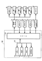
図3〜図7に示されるように、切替部30は、切替ギヤ51と、コイルばね56、57と、切替レバー55とを備えている。
[Switching unit 30]
As shown in FIGS. 3 to 7, the switching unit 30 includes a switching gear 51, coil springs 56 and 57, and a switching lever 55.

図7に示されるように、切替ギヤ51(本発明の駆動ギヤの一例)は、第1ギヤ78と噛合している。これにより、切替ギヤ51は、搬送用モータ71の回転駆動力が伝達されて回転する。また、切替ギヤ51は、第1ギヤ78との噛合を維持した状態で、左右方向9に離間した第1位置(図7(A)参照)と第2位置(図7(B)参照)との間を移動可能である。第1位置は、第2位置よりも左側に位置している。第1位置及び第2位置のいずれも、第1搬送路65よりも右側に位置している。   As shown in FIG. 7, the switching gear 51 (an example of the drive gear of the present invention) meshes with the first gear 78. Thereby, the switching gear 51 is rotated by the rotation driving force of the conveying motor 71 being transmitted. In addition, the switching gear 51 maintains a meshed state with the first gear 78, and the first position (see FIG. 7A) and the second position (see FIG. 7B) separated in the left-right direction 9. It is possible to move between. The first position is located on the left side of the second position. Both the first position and the second position are located on the right side of the first transport path 65.

図7(A)に示されるように、第1位置の切替ギヤ51は、第1ギヤ78と第2出力ギヤ88とに噛合されており、第1出力ギヤ75には噛合されていない。これにより、搬送用モータ71から第1ギヤ78を介して切替ギヤ51に伝達された回転駆動力は、給送駆動伝達部29に伝達される。一方、図7(B)に示されるように、第2位置の切替ギヤ51は、第1ギヤ78と第1出力ギヤ75(本発明の被駆動ギヤの一例)とに噛合されており、第2出力ギヤ88には噛合されていない。これにより、搬送用モータ71から第1ギヤ78を介して切替ギヤ51に伝達された回転駆動力は、第2駆動伝達部27及び第4駆動伝達部28に伝達される。   As shown in FIG. 7A, the switching gear 51 at the first position is meshed with the first gear 78 and the second output gear 88 and is not meshed with the first output gear 75. Thereby, the rotational driving force transmitted from the conveyance motor 71 to the switching gear 51 via the first gear 78 is transmitted to the feeding drive transmission unit 29. On the other hand, as shown in FIG. 7B, the switching gear 51 in the second position is meshed with the first gear 78 and the first output gear 75 (an example of the driven gear of the present invention). The two-output gear 88 is not meshed. Thereby, the rotational driving force transmitted from the transport motor 71 to the switching gear 51 via the first gear 78 is transmitted to the second drive transmission unit 27 and the fourth drive transmission unit 28.

図7に示されるように、切替ギヤ51の右側面には、左右方向9に移動可能な切替レバー55が配置されている。切替レバー55は、図3に示されるように上方に突設されており、キャリッジ40の移動経路内に露出されている。すなわち、切替レバー55は、図3〜図5における左右方向9の右向きに移動するキャリッジ40に当接されて移動する。さらに、切替レバー55の右側には、コイルばね56が取り付けられている。切替レバー55及びコイルばね56は、切替ギヤ51の軸方向に沿って配置されている。コイルばね56は、一端が切替レバー55の右側面に取り付けられており、他端がプリンタ部11のフレーム(不図示)などに取り付けられている。また、切替ギヤ51の左側には、コイルばね57が取り付けられている。コイルばね57は、一端が切替ギヤ51の左側面に取り付けられており、他端がプリンタ部11のフレーム(不図示)などに取り付けられている。   As shown in FIG. 7, a switching lever 55 that can move in the left-right direction 9 is disposed on the right side surface of the switching gear 51. The switching lever 55 protrudes upward as shown in FIG. 3 and is exposed in the movement path of the carriage 40. That is, the switching lever 55 moves in contact with the carriage 40 that moves rightward in the left-right direction 9 in FIGS. Further, a coil spring 56 is attached to the right side of the switching lever 55. The switching lever 55 and the coil spring 56 are disposed along the axial direction of the switching gear 51. One end of the coil spring 56 is attached to the right side surface of the switching lever 55, and the other end is attached to a frame (not shown) of the printer unit 11. A coil spring 57 is attached to the left side of the switching gear 51. One end of the coil spring 57 is attached to the left side surface of the switching gear 51, and the other end is attached to a frame (not shown) of the printer unit 11.

すなわち、切替レバー55は、コイルばね56によって第2位置側から第1位置側(すなわち、左向き)に付勢されており、コイルばね57によって切替ギア51を介して第1位置側から第2位置側(すなわち、右向き)に付勢されている。なお、コイルばね56の付勢力は、コイルばね57の付勢力よりも大きい。したがって、切替レバー55にキャリッジ40が当接されていない状態において、切替ギヤ51は第1位置に位置している。一方、キャリッジ40に当接された切替レバー55が右向きに移動することにより、切替ギヤ51は、コイルばね56の付勢力から解放され、コイルばね57の付勢力によって右向きに移動する。   That is, the switching lever 55 is biased from the second position side to the first position side (ie, leftward) by the coil spring 56, and the second position from the first position side via the switching gear 51 by the coil spring 57. It is biased to the side (ie rightward). The urging force of the coil spring 56 is larger than the urging force of the coil spring 57. Therefore, in a state where the carriage 40 is not in contact with the switching lever 55, the switching gear 51 is located at the first position. On the other hand, when the switching lever 55 in contact with the carriage 40 moves rightward, the switching gear 51 is released from the biasing force of the coil spring 56 and moves rightward by the biasing force of the coil spring 57.

第1位置に位置する切替ギヤ51は、第1ストッパ(不図示)によって、コイルばね56の付勢力による左方への移動が規制されている。これにより、切替ギヤ51は、第1位置に留まることができる。また、切替ギヤ51が第1位置に位置している状態で切替レバー55がキャリッジ40によって右向きに押されると、切替ギヤ51は、第1ストッパによる規制から解放されて、キャリッジ40の押圧力によって第1位置から第2位置へ(すなわち、右向きに)移動する。   The switching gear 51 located at the first position is restricted from moving leftward by the biasing force of the coil spring 56 by a first stopper (not shown). Thereby, the switching gear 51 can remain in the first position. When the switching lever 55 is pushed rightward by the carriage 40 while the switching gear 51 is located at the first position, the switching gear 51 is released from the restriction by the first stopper, and is pressed by the pressing force of the carriage 40. Move from the first position to the second position (ie, to the right).

次に、キャリッジ40と切替レバーとの当接により第1位置から第2位置へ移動した切替ギヤ51は、第2ストッパ(不図示)によって、コイルばね56の付勢力による左方への移動が規制されている。これにより、切替ギヤ51は、第2位置に留まることができる。また、切替ギヤ51が第2位置に位置しているときに切替レバー55がキャリッジ40によってさらに右向きに押されると、切替ギヤ51は、第2ストッパによる規制から開放されて、コイルばね56の付勢力によって第2位置から第1位置へ(すなわち、左方に)移動する。   Next, the switching gear 51 that has moved from the first position to the second position due to the contact between the carriage 40 and the switching lever is moved to the left by the biasing force of the coil spring 56 by a second stopper (not shown). It is regulated. Thereby, the switching gear 51 can remain in the second position. If the switching lever 55 is pushed further right by the carriage 40 when the switching gear 51 is in the second position, the switching gear 51 is released from the restriction by the second stopper, and the coil spring 56 is attached. The force moves from the second position to the first position (ie, to the left).

以上より、切替部30は、第1搬送ローラ60の回転(すなわち、搬送用モータ71の駆動力)を、第2駆動伝達部27及び第4駆動伝達部28、または給送駆動伝達部29への駆動力を伝達するか否かを切り替える。具体的には、切替部30は、切替ギヤ51が第2位置に位置しているとき、第1搬送ローラ60の回転を、第2駆動伝達部27及び第4駆動伝達部28へ伝達し、給送駆動伝達部29へ伝達しない。一方、切替部30は、切替ギヤ51が第1位置に位置しているとき、第1搬送ローラ60の回転を、第2駆動伝達部27及び第4駆動伝達部28へ伝達せず、給送駆動伝達部29へ伝達する。   As described above, the switching unit 30 transmits the rotation of the first conveyance roller 60 (that is, the driving force of the conveyance motor 71) to the second drive transmission unit 27 and the fourth drive transmission unit 28 or the feeding drive transmission unit 29. Whether to transmit the driving force is switched. Specifically, the switching unit 30 transmits the rotation of the first conveyance roller 60 to the second drive transmission unit 27 and the fourth drive transmission unit 28 when the switching gear 51 is located at the second position. It is not transmitted to the feeding drive transmission unit 29. On the other hand, the switching unit 30 does not transmit the rotation of the first conveying roller 60 to the second drive transmission unit 27 and the fourth drive transmission unit 28 when the switching gear 51 is located at the first position. This is transmitted to the drive transmission unit 29.

第4搬送ローラ68へ駆動力を伝達する点に注目すると、切替ギヤ51が第1位置に配置された切替部30は、搬送用モータ71の回転駆動力を第4搬送ローラ68に伝達しない非伝達状態である。一方、切替ギヤ51が第2位置に配置された切替部30は、搬送用モータ71の回転駆動力を第4搬送ローラ68に伝達する伝達状態である。   Paying attention to the point that the driving force is transmitted to the fourth conveying roller 68, the switching unit 30 in which the switching gear 51 is arranged at the first position does not transmit the rotational driving force of the conveying motor 71 to the fourth conveying roller 68. It is a transmission state. On the other hand, the switching unit 30 in which the switching gear 51 is disposed at the second position is in a transmission state in which the rotational driving force of the conveyance motor 71 is transmitted to the fourth conveyance roller 68.

上記構成の駆動伝達機構50において、第1搬送ローラ60と第2搬送ローラ62と第3搬送ローラ45とを逆回転させ、第4搬送ローラ68を順回転させ、給送ローラ25への駆動力の伝達を解除した状態が本発明の第1状態の一例である。本実施形態の第1状態(図8の右端の列の状態)は、切替ギヤ51を第2位置に配置し、且つ搬送用モータ71を逆転駆動させることで実現できる。また、第1搬送ローラ60と第2搬送ローラ62と第3搬送ローラ45と第4搬送ローラ68とを順回転させ、給送ローラ25への駆動力の伝達を解除した状態が本発明の第2状態の一例である。本実施形態の第2状態(図8の右から2番目の列の状態)は、切替ギヤ51を第2位置に配置し、且つ搬送用モータ71を正転駆動させることで実現できる。   In the drive transmission mechanism 50 configured as described above, the first conveying roller 60, the second conveying roller 62, and the third conveying roller 45 are rotated in the reverse direction, the fourth conveying roller 68 is rotated in the forward direction, and the driving force applied to the feeding roller 25 is increased. The state in which the transmission is canceled is an example of the first state of the present invention. The first state of this embodiment (the state of the rightmost column in FIG. 8) can be realized by disposing the switching gear 51 at the second position and driving the transport motor 71 in the reverse direction. The first conveying roller 60, the second conveying roller 62, the third conveying roller 45, and the fourth conveying roller 68 are rotated forward to cancel the transmission of the driving force to the feeding roller 25. It is an example of two states. The second state of the present embodiment (the state of the second row from the right in FIG. 8) can be realized by disposing the switching gear 51 at the second position and driving the transport motor 71 in the forward direction.

また、第1搬送ローラ60と第2搬送ローラ62と第3搬送ローラ45とを順回転させ、第4搬送ローラ68及び給送ローラ25への駆動力の伝達を解除した状態が本発明の第3状態の一例である。本実施形態の第3状態(図8の左端の列の状態)は、切替ギヤ51を第1位置に配置し、且つ搬送用モータ71を正転駆動させることで実現できる。さらに、第1搬送ローラ60を逆回転させ、給送ローラ25を順回転させ、第2搬送ローラ62、第3搬送ローラ45、及び第4搬送ローラ68への駆動力の伝達を解除した状態が第4状態と表記される。第4状態(図8の左から2番目の列の状態)は、切替ギヤ51を第1位置に配置し、且つ搬送用モータ71を逆転駆動させることで実現できる。   The state in which the first conveying roller 60, the second conveying roller 62, and the third conveying roller 45 are rotated forward to release the transmission of the driving force to the fourth conveying roller 68 and the feeding roller 25 is the first aspect of the present invention. It is an example of 3 states. The third state of the present embodiment (the state of the leftmost column in FIG. 8) can be realized by disposing the switching gear 51 at the first position and driving the transport motor 71 in the forward direction. Furthermore, the state where the first conveying roller 60 is reversely rotated, the feeding roller 25 is rotated forward, and the transmission of the driving force to the second conveying roller 62, the third conveying roller 45, and the fourth conveying roller 68 is released. It is described as a fourth state. The fourth state (the state in the second row from the left in FIG. 8) can be realized by disposing the switching gear 51 at the first position and driving the transport motor 71 in the reverse direction.

[制御部130]
図9に示される制御部130は、複合機10の全体動作を制御する。例えば、制御部130は、搬送用モータ71の駆動を制御して各ローラを回転させる。また、制御部130は、キャリッジ駆動用モータ53の駆動を制御してキャリッジ40を移動させる。図9に示されるように、制御部130は、CPU131と、ROM132と、RAM133と、EEPROM134と、ASIC135と、これらを相互に接続する内部バス137とを備えている。
[Control unit 130]
A control unit 130 shown in FIG. 9 controls the overall operation of the multifunction machine 10. For example, the control unit 130 controls driving of the conveyance motor 71 to rotate each roller. The control unit 130 controls the drive of the carriage drive motor 53 to move the carriage 40. As shown in FIG. 9, the control unit 130 includes a CPU 131, a ROM 132, a RAM 133, an EEPROM 134, an ASIC 135, and an internal bus 137 that connects these components to each other.

ROM132には、CPU131が各種動作を制御するためのプログラムなどが格納されている。RAM133は、CPU131が上記プログラムを実行する際に用いるデータや信号等を一時的に記録する記憶領域として使用される。EEPROM134には、電源オフ後も保持すべき設定やフラグ等が格納される。   The ROM 132 stores a program for the CPU 131 to control various operations. The RAM 133 is used as a storage area for temporarily recording data, signals, and the like used when the CPU 131 executes the program. The EEPROM 134 stores settings, flags, and the like that should be retained even after the power is turned off.

ASIC135には、搬送用モータ71及びキャリッジ駆動用モータ53が電気的に接続されている。ASIC135は、各モータを回転させるための駆動信号をCPU131から取得し、駆動信号に応じた駆動電流を対応するモータに出力する。各モータは、ASIC135からの駆動電流によって、所定の回転速度で正転駆動又は逆転駆動する。   A transport motor 71 and a carriage drive motor 53 are electrically connected to the ASIC 135. The ASIC 135 acquires a drive signal for rotating each motor from the CPU 131, and outputs a drive current corresponding to the drive signal to the corresponding motor. Each motor is driven to rotate forward or reversely at a predetermined rotational speed by a drive current from the ASIC 135.

また、ASIC135には、ロータリーエンコーダ73の光学センサ72と、第1センサ160の光学センサ163と、第2センサ170の光学センサ173とが電気的に接続されている。制御部130は、光学センサ72から取得したパルス信号に基づいて、各搬送ローラ60、62、45の回転量を検知する。また、制御部130は、各光学センサ163、173からの検知信号に基づいて記録用紙12の位置を検知する。   Further, the optical sensor 72 of the rotary encoder 73, the optical sensor 163 of the first sensor 160, and the optical sensor 173 of the second sensor 170 are electrically connected to the ASIC 135. The control unit 130 detects the rotation amount of each of the transport rollers 60, 62, 45 based on the pulse signal acquired from the optical sensor 72. The control unit 130 detects the position of the recording paper 12 based on detection signals from the optical sensors 163 and 173.

[制御部130による制御]
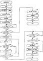
以下、記録用紙12の両面に画像を記録する処理の手順が、図10のフローチャートに基づいて説明される。なお、図10の処理は、制御部130によって実行される。また、図10では、分岐位置36においてスイッチバックされた記録用紙12が、第2搬送路67を通過して合流位置37から再び第1搬送路65へ送り込まれる処理の手順が、特に詳細に説明される。
[Control by control unit 130]
Hereinafter, a procedure of processing for recording an image on both sides of the recording paper 12 will be described based on the flowchart of FIG. 10 is executed by the control unit 130. In FIG. 10, the procedure of the process in which the recording paper 12 switched back at the branch position 36 passes through the second conveyance path 67 and is sent again from the joining position 37 to the first conveyance path 65 will be described in detail. Is done.

まず、複合機10に画像記録指示が入力されると、制御部130は、駆動伝達機構50を第4状態にする。すなわち、制御部130は、切替ギヤ51を第1位置に配置し、且つ搬送用モータ71を逆転駆動させる。これにより、給送トレイ20に載置された記録用紙12が給紙ローラ25によって第1搬送路65に送り出される(S11)。   First, when an image recording instruction is input to the multifunction device 10, the control unit 130 sets the drive transmission mechanism 50 to the fourth state. That is, the control unit 130 arranges the switching gear 51 at the first position and drives the transport motor 71 in the reverse direction. Accordingly, the recording paper 12 placed on the feeding tray 20 is sent out to the first transport path 65 by the paper feed roller 25 (S11).

次に、制御部130は、記録用紙12の第1搬送向き15の下流側の端部(すなわち、先端)が第1センサ160に到達したと判断すると、位置判断処理及びサイズ判断処理を開始する(S12)。なお、記録用紙12の先端が第1センサ160に到達したことは、第1センサ160から出力される検知信号がローレベル信号からハイレベル信号に変化したことによって判断される。   Next, when the control unit 130 determines that the downstream end (that is, the leading end) of the recording paper 12 in the first conveyance direction 15 has reached the first sensor 160, the control unit 130 starts position determination processing and size determination processing. (S12). Note that the leading edge of the recording paper 12 has reached the first sensor 160 is determined by a change in the detection signal output from the first sensor 160 from a low level signal to a high level signal.

制御部130は、位置判断処理において、ロータリーエンコーダ73のパルス信号の数(ハイレベル信号の数)を、記録用紙12の先端が第1センサ160に到達した時点からカウントする。そして、制御部130は、例えば、カウントしたパルス信号の数が閾値(第1センサ160から第1搬送ローラ60の距離に相当する予め定められた値)に達した時点で、記録用紙12の先端が第1搬送ローラ60に到達したと判断する。なお、位置判断処理では、第1センサ160から各構成要素(例えば、第3搬送ローラ45或いは第4搬送ローラ68等)までの距離に相当する複数の閾値を保持しておくことによって、記録用紙12の先端が各構成要素に到達したことを判断できる。また、記録用紙12の第1搬送向き15の上流側の端部(すなわち、後端)が第1センサ160に到達した時点からのパルス信号の数をカウントすることにより、記録用紙12の後端の位置を判断できる。パルス信号のカウントは、記録用紙12が排出トレイ21に排出されるまで継続される。   In the position determination process, the control unit 130 counts the number of pulse signals (the number of high level signals) of the rotary encoder 73 from the time when the leading edge of the recording paper 12 reaches the first sensor 160. Then, for example, when the number of counted pulse signals reaches a threshold value (a predetermined value corresponding to the distance from the first sensor 160 to the first transport roller 60), the control unit 130 detects the leading edge of the recording paper 12. Is determined to have reached the first conveying roller 60. In the position determination process, a plurality of threshold values corresponding to the distance from the first sensor 160 to each component (for example, the third conveyance roller 45 or the fourth conveyance roller 68) are held, thereby recording paper. It can be determined that 12 tips have reached each component. Further, by counting the number of pulse signals from the time when the upstream end (that is, the rear end) of the recording paper 12 in the first conveyance direction 15 reaches the first sensor 160, the rear end of the recording paper 12 is counted. Can be determined. The counting of the pulse signal is continued until the recording paper 12 is discharged to the discharge tray 21.

なお、位置判断処理は、第1センサ160のみならず、第2センサ170を用いて行うこともできる。すなわち、制御部130は、第2センサ170から各構成要素までの距離に相当する閾値を予め保持しておき、記録用紙12の先端或いは後端が第2センサ170を通過した時点からロータリーエンコーダ73のパルス信号をカウントし、カウントしたパルス信号と閾値とを比較することによって記録用紙12の位置を判断できる。例えば、記録用紙12の先端が第1搬送ローラ60に到達したこと、及び記録用紙12の先端が記録部24に対向する印刷開始位置に到達したことは、第1センサ160に到達した時点を基準として判断すればよい。一方、記録用紙12の後端が経路切替部材41の補助ローラ47を通過したこと、及び記録用紙12の後端が第3搬送ローラ45を通過したことは、第2センサ170に到達した時点を基準として判断すればよい。   Note that the position determination process can be performed using not only the first sensor 160 but also the second sensor 170. That is, the control unit 130 holds a threshold corresponding to the distance from the second sensor 170 to each component in advance, and the rotary encoder 73 from the time when the leading edge or the trailing edge of the recording paper 12 passes through the second sensor 170. The position of the recording paper 12 can be determined by counting the number of pulse signals and comparing the counted pulse signal with a threshold value. For example, the fact that the leading edge of the recording paper 12 has reached the first transport roller 60 and that the leading edge of the recording paper 12 has reached the print start position facing the recording unit 24 are based on the time when the first sensor 160 is reached. You can judge as. On the other hand, the fact that the trailing edge of the recording paper 12 has passed through the auxiliary roller 47 of the path switching member 41 and the fact that the trailing edge of the recording paper 12 has passed through the third transport roller 45 indicate when the second sensor 170 has been reached. What is necessary is just to judge as a standard.

また、制御部130は、サイズ判断処理において、記録用紙12の先端が第1センサ160に到達した時点から、記録用紙12の後端が第1センサ160を通過(すなわち、第1センサ160の検知信号がハイレベル信号からローレベル信号に変化)するまでの間のパルス信号の数によって、記録用紙12のサイズを判断する。すなわち、カウントされるパルス信号の数が多いほど、記録用紙12のサイズが大きいことが分かる。なお、サイズ判断処理においては、記録用紙12の種類(A4、B5等)が判断されてもよいし、第1搬送向き15に沿う記録用紙12の長さのみが判断されてもよい。また、上述のサイズ判断処理に代えて、ユーザに記録用紙12のサイズを入力させてもよい。   Further, in the size determination process, the control unit 130 causes the trailing edge of the recording paper 12 to pass through the first sensor 160 from the time when the leading edge of the recording paper 12 reaches the first sensor 160 (that is, detection by the first sensor 160). The size of the recording paper 12 is determined based on the number of pulse signals until the signal changes from a high level signal to a low level signal. That is, it can be seen that the larger the number of pulse signals counted, the larger the size of the recording paper 12. In the size determination process, the type (A4, B5, etc.) of the recording paper 12 may be determined, or only the length of the recording paper 12 along the first transport direction 15 may be determined. Further, instead of the above-described size determination process, the user may input the size of the recording paper 12.

次に、記録用紙12の先端が第1搬送ローラ60に到達したと判断されると、制御部130は、駆動伝達機構50を第4状態から第3状態に切り替える(S13)。すなわち、制御部130は、切替ギヤ51を第1位置から移動させず、搬送用モータ71を逆転駆動から正転駆動に切り替える。これにより、第1搬送ローラ60が順回転し、記録用紙12を第1搬送向き15に搬送する。   Next, when it is determined that the leading edge of the recording paper 12 has reached the first conveyance roller 60, the control unit 130 switches the drive transmission mechanism 50 from the fourth state to the third state (S13). That is, the control unit 130 does not move the switching gear 51 from the first position, and switches the transport motor 71 from the reverse drive to the normal drive. As a result, the first transport roller 60 rotates forward and transports the recording paper 12 in the first transport direction 15.

そして、制御部130は、記録用紙12の表面に対する画像記録(以下、「表面印刷」と表記する。)が完了し(S14)、第2センサ170を用いた位置判断処理によって記録用紙12の後端が経路切替部材41の補助ローラ47を通過したと判断すると、駆動伝達機構50を第3状態から第1状態に切り替える(S15)。すなわち、制御部130は、正転駆動している搬送用モータ71を一旦停止させ、キャリッジ40を切替レバー55に当接させて切替ギヤ51を第1位置から第2位置に移動させた後で搬送用モータ71を逆転駆動させる。これにより、記録用紙12は、第1搬送向き15の上流側の端部を先端として、分岐位置36から第2搬送路67に進入し、第2搬送路67を第2搬送向き16に搬送される。   Then, the control unit 130 completes image recording on the surface of the recording paper 12 (hereinafter referred to as “front surface printing”) (S14), and the position determination process using the second sensor 170 performs the rear of the recording paper 12. If it is determined that the end has passed the auxiliary roller 47 of the path switching member 41, the drive transmission mechanism 50 is switched from the third state to the first state (S15). In other words, the control unit 130 temporarily stops the forward driving motor 71, contacts the carriage 40 with the switching lever 55, and moves the switching gear 51 from the first position to the second position. The conveyance motor 71 is driven in reverse. As a result, the recording paper 12 enters the second transport path 67 from the branch position 36 with the upstream end of the first transport direction 15 as the leading end, and is transported in the second transport direction 16 through the second transport path 67. The

次に、制御部130は、第1センサ160を用いた位置判断処理によって第2搬送路67を搬送された記録用紙12の先端が第1搬送ローラ60に到達したか否かを判断する(S16)。記録用紙12の先端が第1搬送ローラ60に到達したと判断された場合(S16:Yes)、制御部130は、サイズ判断処理の結果を用いて、記録用紙12の後端が第3搬送ローラ45を通過したか否かを判断する(S17)。   Next, the control unit 130 determines whether or not the leading edge of the recording paper 12 conveyed through the second conveyance path 67 by the position determination process using the first sensor 160 has reached the first conveyance roller 60 (S16). ). When it is determined that the leading edge of the recording paper 12 has reached the first conveyance roller 60 (S16: Yes), the control unit 130 uses the result of the size determination process to determine that the trailing edge of the recording paper 12 is the third conveyance roller. It is determined whether or not it has passed 45 (S17).

具体的には、制御部130は、サイズ判断処理によって判断された記録用紙12のサイズと、第3搬送ローラ45から第2搬送路67を通って第1搬送ローラ60に至る搬送距離(以下、「閾値距離」と表記する)とを比較する。そして、記録用紙12のサイズが閾値距離以上であれば、記録用紙12の先端が第1搬送ローラ60に到達した時点において、記録用紙12の後端が第3搬送ローラ45を未だ通過していないと判断できる(S17:No)。一方、記録用紙12のサイズが閾値距離未満であれば、記録用紙12の先端が第1搬送ローラ60に到達した時点において、記録用紙12の後端が第3搬送ローラ45を通過したと判断できる(S17:Yes)。   Specifically, the control unit 130 determines the size of the recording paper 12 determined by the size determination process, and the transport distance from the third transport roller 45 through the second transport path 67 to the first transport roller 60 (hereinafter referred to as “the transport distance”). (Referred to as “threshold distance”). If the size of the recording paper 12 is equal to or greater than the threshold distance, the trailing edge of the recording paper 12 has not yet passed through the third transport roller 45 when the leading edge of the recording paper 12 reaches the first transport roller 60. (S17: No). On the other hand, if the size of the recording paper 12 is less than the threshold distance, it can be determined that the trailing edge of the recording paper 12 has passed the third transport roller 45 when the leading edge of the recording paper 12 reaches the first transport roller 60. (S17: Yes).

記録用紙12の後端が第3搬送ローラ45を通過していないと判断された場合(S17:No)、制御部130は、駆動伝達機構50を第1状態から第2状態に切り替える処理である第1切替処理を実行する(S18)。具体的には、制御部130は、切替ギヤ51を第2位置から移動させず、搬送用モータ71を逆転駆動から正転駆動に切り替える。なお、逆回転する第1搬送ローラ60(すなわち、搬送ローラ対)に記録用紙12の先端を当接させた後で第1切替処理を実行することにより、記録用紙12の斜行を矯正できる。   When it is determined that the trailing edge of the recording paper 12 has not passed through the third conveyance roller 45 (S17: No), the control unit 130 is a process of switching the drive transmission mechanism 50 from the first state to the second state. A first switching process is executed (S18). Specifically, the control unit 130 does not move the switching gear 51 from the second position, and switches the conveyance motor 71 from the reverse rotation drive to the normal rotation drive. The skew of the recording paper 12 can be corrected by executing the first switching process after the front end of the recording paper 12 is brought into contact with the first transport roller 60 (that is, the pair of transport rollers) that rotates in reverse.

次に、制御部130は、記録用紙12に対して画像記録を行う記録処理を実行する(S19)。具体的には、制御部130は、記録用紙12を第1搬送向き15に沿う所定の幅単位で第1搬送ローラ60に搬送させ、これによって記録部24に対向された記録用紙12の領域に、画像記録を行う。なお、ステップS19では、記録用紙12の裏面(すなわち、表面印刷と反対の面)に対する画像記録(以下、「裏面印刷」と表記する。)が行われる。また、ステップS19の1回の処理では、記録用紙12の裏面の一部(すなわち、上述の所定の幅)にのみ画像が記録される。すなわち、記録用紙12の裏面全体に画像を記録するためには、ステップS19の処理を繰り返し実行する必要がある。   Next, the control unit 130 executes a recording process for recording an image on the recording paper 12 (S19). Specifically, the control unit 130 conveys the recording sheet 12 to the first conveying roller 60 in a predetermined width unit along the first conveying direction 15, thereby causing the recording sheet 12 to face the area of the recording sheet 12 facing the recording unit 24. And image recording. In step S19, image recording (hereinafter referred to as “back surface printing”) is performed on the back surface of the recording paper 12 (that is, the surface opposite to the front surface printing). Further, in one process of step S19, an image is recorded only on a part of the back surface of the recording paper 12 (that is, the predetermined width described above). That is, in order to record an image on the entire back surface of the recording paper 12, it is necessary to repeatedly execute the process of step S19.

次に、制御部130は、ステップS19において記録用紙12が所定の幅だけ搬送されたことによって、記録用紙12の後端が第3搬送ローラ45(すなわち、反転ローラ対)を通過したか否かを判断する(S20)。ステップS20は、例えば以下のような処理によって、記録用紙12の後端が第3搬送ローラ45を通過したか否かが判断される。   Next, the control unit 130 determines whether or not the rear end of the recording paper 12 has passed the third conveyance roller 45 (that is, the reverse roller pair) due to the recording paper 12 being conveyed by a predetermined width in step S19. Is determined (S20). In step S20, it is determined whether or not the trailing edge of the recording paper 12 has passed through the third transport roller 45 by the following process, for example.

まず、制御部130は、サイズ判断処理において判断された用紙サイズに基づいて、記録用紙12の先端が第1搬送ローラ60に到達した時点(すなわち、S16:Yesと判断された時点)において、記録用紙12の後端が第3搬送ローラ45を通過するのに必要な搬送量(以下、「必要搬送量」と表記する)を算出できる。そこで、制御部130は、記録用紙12の先端が第1搬送ローラ60に到達した時点からロータリーエンコーダ73のパルス信号のカウントを開始し、カウントしたパルス信号の数が必要搬送量に相当する数に達した時点で、記録用紙12の後端が第3搬送ローラ45を通過したと判断する。   First, based on the paper size determined in the size determination process, the control unit 130 records when the leading edge of the recording paper 12 reaches the first transport roller 60 (that is, when it is determined S16: Yes). A conveyance amount necessary for the rear end of the sheet 12 to pass through the third conveyance roller 45 (hereinafter referred to as “necessary conveyance amount”) can be calculated. Therefore, the control unit 130 starts counting the pulse signals of the rotary encoder 73 from the time when the leading edge of the recording paper 12 reaches the first conveyance roller 60, and the number of counted pulse signals is a number corresponding to the necessary conveyance amount. At this point, it is determined that the trailing edge of the recording paper 12 has passed through the third conveyance roller 45.

記録用紙12の後端が第3搬送ローラ45を通過したと判断された場合(S20:Yes)、制御部130は、駆動伝達機構50を第2状態から第3状態に切り替える処理である第2切替処理を実行する(S21)。具体的には、制御部130は、キャリッジ40を切替レバー55に当接させて切替ギヤ51を第2位置から第1位置に移動させる。これにより、搬送用モータ71から第4搬送ローラ68への駆動力の伝達が解除されるので、第4搬送ローラ68は、記録用紙12が第2搬送向き16に搬送されるのに伴って連れ回るだけとなる。一方、記録用紙12の後端が第3搬送ローラ45を未だ通過していないと判断された場合(S20:No)、ステップS21はスキップされる。   When it is determined that the trailing edge of the recording paper 12 has passed through the third transport roller 45 (S20: Yes), the control unit 130 is a process for switching the drive transmission mechanism 50 from the second state to the third state. A switching process is executed (S21). Specifically, the controller 130 moves the switching gear 51 from the second position to the first position by bringing the carriage 40 into contact with the switching lever 55. As a result, the transmission of the driving force from the conveyance motor 71 to the fourth conveyance roller 68 is released, so that the fourth conveyance roller 68 moves along with the conveyance of the recording paper 12 in the second conveyance direction 16. It only turns around. On the other hand, when it is determined that the trailing edge of the recording paper 12 has not yet passed through the third transport roller 45 (S20: No), step S21 is skipped.

次に、制御部130は、記録用紙12に対する裏面印刷が終了したか否かを判断する(S22)。裏面印刷が未だ終了していなければ(S22:No)、ステップS19〜S21の処理が再び実行される。すなわち、繰り返し実行されるステップS19の裏面印刷の合間に記録用紙12の後端が第3搬送ローラ45を通過したと判断されると(S20:Yes)、第2切替処理が実行される(S21)。換言すれば、第2切替処理は、裏面印刷が行われていないタイミングで実行される。   Next, the control unit 130 determines whether or not the back side printing on the recording paper 12 is completed (S22). If the back side printing has not been completed yet (S22: No), the processes of steps S19 to S21 are executed again. That is, if it is determined that the trailing edge of the recording paper 12 has passed through the third transport roller 45 between the repeated backside printing in step S19 (S20: Yes), the second switching process is executed (S21). ). In other words, the second switching process is executed at a timing when the back side printing is not performed.

一方、裏面印刷が終了すると(S22:Yes)、制御部130は、記録用紙12の後端が第3搬送ローラ45を通過したか否かを再び判断する(S23)。ステップS23における判断の手法はステップS20と共通するので、再度の説明は省略される。記録用紙12が未だ第3搬送ローラ45に挟持されている場合(S23:No)、制御部130は、記録用紙12の後端が第3搬送ローラ45を通過するまで、第1搬送ローラ60及び第4搬送ローラ68に記録用紙12を搬送させる。   On the other hand, when the back side printing is finished (S22: Yes), the control unit 130 determines again whether or not the rear end of the recording paper 12 has passed through the third conveyance roller 45 (S23). Since the determination method in step S23 is the same as that in step S20, description thereof is omitted. When the recording paper 12 is still nipped by the third conveyance roller 45 (S23: No), the control unit 130 determines that the first conveyance roller 60 and the recording paper 12 until the rear end of the recording paper 12 passes through the third conveyance roller 45. The recording paper 12 is conveyed to the fourth conveyance roller 68.

そして、記録用紙12の後端が第3搬送ローラ45を通過した場合(S23:Yes)、制御部130は、ステップS21において第2切替処理が実行されたか否かを判断する(S24)。ステップS21において第2切替処理が実行されていなければ(S24:No)、制御部130は、第2切替処理(S25)を実行し、更に搬送用モータ71の正逆転を行う(S26)。一方、ステップS21において第2切替処理が実行されていれば(S24:Yes)、ステップS25、S26はスキップされる。   If the trailing edge of the recording paper 12 has passed the third transport roller 45 (S23: Yes), the control unit 130 determines whether or not the second switching process has been executed in step S21 (S24). If the second switching process is not executed in step S21 (S24: No), the control unit 130 executes the second switching process (S25), and further performs forward / reverse rotation of the transport motor 71 (S26). On the other hand, if the second switching process is executed in step S21 (S24: Yes), steps S25 and S26 are skipped.

なお、搬送用モータ71の正逆転とは、搬送用モータ71が正転駆動された後で逆転駆動される動作、或いは逆転駆動された後で正転駆動される動作を、少なくとも一回実行するというものである。例えば、搬送用モータ71は、正転駆動された後で逆転駆動される動作を繰り返して5回実行する。また、搬送用モータ71の正転駆動及び逆転駆動の各々の駆動量は、少なくとも切替ギヤ51、第1出力ギヤ75、及び第2出力ギヤ88それぞれにおける隣接する歯の隙間以上の回転量である。   Note that the forward / reverse rotation of the transport motor 71 executes at least one operation in which the transport motor 71 is driven in reverse after being driven forward, or forward driven after being driven in reverse. That's it. For example, the conveyance motor 71 repeats the operation of being driven in the reverse direction after being driven in the normal direction, and is executed five times. Further, the respective drive amounts of the forward drive and the reverse drive of the transport motor 71 are rotation amounts that are at least equal to or greater than the gap between adjacent teeth in the switching gear 51, the first output gear 75, and the second output gear 88, respectively. .

そして、制御部130は、記録用紙12の後端が第3搬送ローラ45を第1向き15に通過するまで搬送用モータ71を正転駆動させ、記録用紙12を排出トレイ21に排出する(S27)。記録用紙12の後端が第3搬送ローラ45を通過したか否かは、第2センサ170を用いた位置判断処理によって行うことができる。   Then, the control unit 130 drives the transport motor 71 to rotate forward until the rear end of the recording paper 12 passes through the third transport roller 45 in the first direction 15, and discharges the recording paper 12 to the discharge tray 21 (S27). ). Whether or not the trailing edge of the recording paper 12 has passed through the third conveyance roller 45 can be determined by position determination processing using the second sensor 170.

一方、ステップS17において、記録用紙12の後端が第3搬送ローラ45を既に通過していたと判断された場合(S17:Yes)、制御部130は、駆動伝達機構50を第1状態から第3状態に切り替える(S28)。具体的には、制御部130は、逆転駆動している搬送用モータ71を一旦停止させ、切替ギヤ51を第2位置から第1位置へ移動させた後で搬送用モータ71を正転駆動させる。次に、制御部130は、記録用紙12の裏面に対して裏面印刷を行う(S29)。ステップS29における裏面印刷は、記録用紙12の全体に画像が記録されるまで行われる。そして、制御部130は、記録用紙12を排出トレイ21に排出する(S30)。この処理はステップS27と共通するので、再度の説明は省略される。   On the other hand, when it is determined in step S17 that the trailing edge of the recording paper 12 has already passed through the third conveyance roller 45 (S17: Yes), the control unit 130 moves the drive transmission mechanism 50 from the first state to the third state. The state is switched (S28). Specifically, the control unit 130 temporarily stops the conveyance motor 71 that is driven in reverse rotation, moves the switching gear 51 from the second position to the first position, and then drives the conveyance motor 71 in the normal direction. . Next, the control unit 130 performs back side printing on the back side of the recording paper 12 (S29). The back side printing in step S29 is performed until an image is recorded on the entire recording paper 12. Then, the control unit 130 discharges the recording paper 12 to the discharge tray 21 (S30). Since this process is common to step S27, a re-explanation is omitted.

[実施形態の効果]
本実施形態によれば、記録用紙12の後端が反転ローラ対を通過し且つ再搬送ローラ対を通過するまでの期間に再搬送ローラ対への駆動力の伝達を解除する。これにより、記録用紙12は搬送ローラ対のみによって搬送され、再搬送ローラは連れ回るだけとなる。その結果、搬送ローラ対及び再搬送ローラ対の単位時間当たりの搬送量が異なることに起因する不具合を抑制できる。
[Effect of the embodiment]
According to this embodiment, the transmission of the driving force to the re-conveying roller pair is canceled during the period until the trailing edge of the recording paper 12 passes the reversing roller pair and the re-conveying roller pair. As a result, the recording paper 12 is transported only by the transport roller pair, and the re-transport roller is only rotated. As a result, it is possible to suppress problems caused by the difference in the transport amount per unit time between the transport roller pair and the re-transport roller pair.

また、本実施形態によれば、第1切替処理(第1状態から第2状態への切り替え)は搬送用モータ71の回転向きを切り替えるだけあり、第2切替処理(第2状態から第3状態への切り替え)は切替部30の切替ギヤ51を第2位置から第1位置へ移動させるだけである。特に、記録用紙12のサイズが大きい場合には裏面印刷中に第2切替処理が行われる可能性があるので、第2切替処理において搬送用モータ71の回転向きを変更しないことにより、記録用紙12の位置ズレを防止できる。   Further, according to the present embodiment, the first switching process (switching from the first state to the second state) only switches the rotation direction of the transport motor 71, and the second switching process (from the second state to the third state). Switching) only moves the switching gear 51 of the switching unit 30 from the second position to the first position. In particular, when the size of the recording paper 12 is large, there is a possibility that the second switching process may be performed during the reverse side printing. Therefore, by not changing the rotation direction of the conveyance motor 71 in the second switching process, the recording paper 12 Can be prevented from being displaced.

また、本実施形態によれば、第1切替処理によって、第1搬送ローラ60、第3搬送ローラ45、及び第4搬送ローラ68は共に順回転する。その結果、第1搬送ローラ60は記録用紙12を第1搬送向き15に搬送しようとし、第4搬送ローラ68は記録用紙12を第2搬送向き16に搬送しようとし、第3搬送ローラ45は記録用紙12を第1搬送向き15に搬送しようとする。そのため、第1搬送ローラ60及び第4搬送ローラ68が搬送する記録用紙12を第3搬送ローラ45が逆向きに引っ張ることになる。しかしながら、主に第3搬送ローラ45と第4搬送ローラ68との間で逆向きの搬送力が相殺(すなわち、引っ張り合い)されるので、第1搬送ローラ60は、記録用紙12を逆向きに搬送しようとする第3搬送ローラ45に大きく影響されることなく、記録用紙12を適切に搬送できる。   Further, according to the present embodiment, the first transport roller 60, the third transport roller 45, and the fourth transport roller 68 are all rotated forward by the first switching process. As a result, the first transport roller 60 attempts to transport the recording paper 12 in the first transport direction 15, the fourth transport roller 68 attempts to transport the recording paper 12 in the second transport direction 16, and the third transport roller 45 performs the recording. An attempt is made to transport the paper 12 in the first transport direction 15. Therefore, the third transport roller 45 pulls the recording paper 12 transported by the first transport roller 60 and the fourth transport roller 68 in the reverse direction. However, since the reverse conveyance force is canceled (ie, pulled) mainly between the third conveyance roller 45 and the fourth conveyance roller 68, the first conveyance roller 60 causes the recording paper 12 to be reversed. The recording paper 12 can be appropriately conveyed without being greatly affected by the third conveying roller 45 to be conveyed.

また、本実施形態によれば、間欠的に実行される裏面印刷(S19)の合間に第2切替処理を実行するので、裏面印刷のスループットを低下させることなく、第2切替処理を実行できる。また、第2切替処理を複数回実行することにより、第2状態から第3状態への切り替えを確実に行うことができる。なお、図10の例では、1回の裏面印刷(S19)が終了する度に第2切替処理の要否を判断(S20)しているが、本発明はこれに限定されない。すなわち、第2切替処理(S21)は、所定の回数(1回以上)の裏面印刷が終了したタイミングで実行されればよい。   Further, according to the present embodiment, since the second switching process is executed between the intermittently executed back surface printing (S19), the second switching process can be executed without reducing the throughput of the back surface printing. In addition, by executing the second switching process a plurality of times, switching from the second state to the third state can be reliably performed. In the example of FIG. 10, it is determined whether or not the second switching process is necessary (S20) every time one back side printing (S19) is completed, but the present invention is not limited to this. That is, the second switching process (S21) may be executed at a timing when the back side printing is completed a predetermined number of times (one or more times).

また、記録用紙12に対する裏面印刷が終了した後に(S22:Yes)、ステップS25において第2切替処理を実行する場合は記録用紙12の位置ズレを防止する必要性が低い。そこで、本実施形態では、ステップS26において搬送用モータ71の正逆転を実行することにより、第2状態から第3状態への切り替えをより確実に行うことができる。なお、図10の例では、画像記録が終了した後で第2切替処理を実行する場合にのみ搬送用モータ71の正逆転を実行しているが、本発明はこれに限定されない。すなわち、どのタイミングで第2切替処理が実行された場合でも、画像記録が終了した後に搬送用モータ71の正逆転を実行するようにしてもよい。   Further, when the second switching process is executed in step S25 after the back side printing on the recording paper 12 is completed (S22: Yes), it is less necessary to prevent the recording paper 12 from being misaligned. Therefore, in this embodiment, the forward / reverse rotation of the transport motor 71 is executed in step S26, so that the switching from the second state to the third state can be performed more reliably. In the example of FIG. 10, the forward / reverse rotation of the conveyance motor 71 is executed only when the second switching process is executed after the image recording is completed, but the present invention is not limited to this. That is, regardless of the timing at which the second switching process is executed, the forward / reverse rotation of the transport motor 71 may be executed after the image recording is completed.

また、本実施形態によれば、第4搬送ローラ68をアーム70によって従動ローラ69に当接させている。また、アーム70の回動端は、第4搬送ローラ68の支持端より第2搬送向き16の上流側に位置している。その結果、第3搬送ローラ45が記録用紙12を第1搬送向き15に搬送しようとすると、第4搬送ローラ68を従動ローラ69に圧接する向きにアーム70が回動するので、第2状態において第3搬送ローラ45が記録用紙12を引っ張る力に抗して、当該記録用紙12を第2搬送向き16に搬送できる。   Further, according to the present embodiment, the fourth conveying roller 68 is brought into contact with the driven roller 69 by the arm 70. The pivot end of the arm 70 is located upstream of the support end of the fourth transport roller 68 in the second transport direction 16. As a result, when the third transport roller 45 tries to transport the recording paper 12 in the first transport direction 15, the arm 70 rotates in the direction in which the fourth transport roller 68 is pressed against the driven roller 69. The recording paper 12 can be conveyed in the second conveyance direction 16 against the force with which the third conveyance roller 45 pulls the recording paper 12.

さらに、本実施形態では、再搬送ローラ対の単位時間当たりの搬送量を、搬送ローラ対の単位時間当たりの搬送量より大きくした例を説明したが、本発明はこれに限定されない。搬送ローラ対と再搬送ローラ対との単位時間当たりの搬送量を完全に一致させるのは非常に困難であり、本発明は、搬送ローラ対と再搬送ローラ対との単位時間当たりの搬送量が異なる場合に、特に有効である。   Furthermore, in the present embodiment, the example in which the conveyance amount per unit time of the re-conveyance roller pair is larger than the conveyance amount per unit time of the conveyance roller pair has been described, but the present invention is not limited to this. It is very difficult to completely match the transport amount per unit time between the transport roller pair and the re-transport roller pair. In the present invention, the transport amount per unit time between the transport roller pair and the re-transport roller pair is This is particularly effective when different.

なお、図8に示される搬送用モータ71の正転駆動及び逆転駆動と、各ローラ対の順回転及び逆回転との組み合わせは一例であり、本発明はこれに限定されない。すなわち、駆動伝達機構50は、搬送用モータ71の正転駆動及び逆転駆動の一方によって搬送ローラ対及び反転ローラ対を順回転させ、搬送用モータ71の正転駆動及び逆転駆動の他方によって搬送ローラ対及び反転ローラ対を逆回転させ、更に搬送用モータ71の回転(正転駆動及び逆転駆動の双方)によって再搬送ローラ対を順回転させることができる構成であればよい。   The combination of forward drive and reverse drive of the conveyance motor 71 shown in FIG. 8 and forward rotation and reverse rotation of each roller pair is an example, and the present invention is not limited to this. In other words, the drive transmission mechanism 50 rotates the conveyance roller pair and the reverse roller pair in the forward direction by one of the normal rotation drive and the reverse rotation drive of the conveyance motor 71, and the conveyance roller by the other of the normal rotation drive and the reverse rotation drive of the conveyance motor 71. Any configuration may be used as long as the pair and the reverse roller pair can be rotated in the reverse direction and the re-conveying roller pair can be rotated in the forward direction by the rotation of the conveying motor 71 (both forward rotation and reverse rotation).

また、上記の実施形態における第4駆動伝達部28の構成は一例であり、本発明はこれに限定されない。例えば、振子ギヤ111及びアーム113を省略し、振子ギヤ110を正転噛合ギヤ104及び逆転噛合ギヤ105に噛合させる構成であってもよい。すなわち、第4駆動伝達部28は、太陽ギヤ109の第1向き及び第2向きの一方の回転を奇数個のギヤによって第4搬送ローラ68の駆動軸に伝達し、太陽ギヤの109の他方の回転を偶数個のギヤによって第4搬送ローラ68の駆動軸に伝達できる構成であればよい。   In addition, the configuration of the fourth drive transmission unit 28 in the above embodiment is an example, and the present invention is not limited to this. For example, the pendulum gear 111 and the arm 113 may be omitted, and the pendulum gear 110 may be engaged with the forward meshing gear 104 and the reverse meshing gear 105. That is, the fourth drive transmission unit 28 transmits one rotation of the sun gear 109 in the first direction and the second direction to the drive shaft of the fourth transport roller 68 by an odd number of gears, and the other of the sun gear 109 Any configuration may be used as long as the rotation can be transmitted to the drive shaft of the fourth conveying roller 68 by an even number of gears.

11・・・プリンタ部
15・・・第1搬送向き
16・・・第2搬送向き
24・・・記録部
26・・・第1駆動伝達部
27・・・第2駆動伝達部
28・・・第4駆動伝達部
30・・・切替部
33・・・第3駆動伝達部
36・・・分岐位置
37・・・合流位置
38・・・記録ヘッド
40・・・キャリッジ
50・・・駆動伝達機構
51・・・切替ギヤ
55・・・切替レバー
65・・・第1搬送路
67・・・第2搬送路
68・・・第4搬送ローラ
69・・・従動ローラ
70・・・アーム
71・・・搬送用モータ
73・・・ロータリーエンコーダ
130・・・制御部
160・・・第1センサ
DESCRIPTION OF SYMBOLS 11 ... Printer part 15 ... 1st conveyance direction 16 ... 2nd conveyance direction 24 ... Recording part 26 ... 1st drive transmission part 27 ... 2nd drive transmission part 28 ... 4th drive transmission part 30 ... switching part 33 ... 3rd drive transmission part 36 ... branch position 37 ... merge position 38 ... recording head 40 ... carriage 50 ... drive transmission mechanism 51 ... switching gear 55 ... switching lever 65 ... first transport path 67 ... second transport path 68 ... fourth transport roller 69 ... driven roller 70 ... arm 71 ...・ Conveying motor 73... Rotary encoder 130... Control unit 160.

Claims (11)

シートが第1搬送向きに搬送される第1搬送路と、分岐位置において上記第1搬送路から分岐し且つ上記分岐位置より上記第1搬送向きの上流側の合流位置において上記第1搬送路に合流しており、上記分岐位置から上記合流位置に向かう第2搬送向きにシートが搬送される第2搬送路とが形成された本体と、
上記合流位置より上記第1搬送向きの下流側において上記第1搬送路に設けられており、上記第1搬送路上のシートを上記第1搬送向きに搬送する順回転、及び順回転と逆向きの逆回転が可能な搬送ローラ対と、
上記搬送ローラ対より上記第1搬送向きの下流側で且つ上記分岐位置より上記第1搬送向きの上流側において上記第1搬送路に設けられており、上記搬送ローラ対によって搬送されたシートに画像記録を行う記録部と、
上記分岐位置より上記第1搬送向きの下流側において上記第1搬送路に設けられており、上記記録部によって画像が記録されたシートを、上記第1搬送向きに搬送する順回転、及び上記第1搬送向きの上流側の端部を先端として上記第2搬送路へ搬送する逆回転が可能な反転ローラ対と、
上記第2搬送路に設けられており、上記反転ローラ対によって上記第2搬送路に搬送されたシートを上記第2搬送向きに搬送する順回転が可能な再搬送ローラ対と、
1以上のモータを含む駆動源と上記駆動源の駆動力を伝達する伝達機構とで構成されており、上記反転ローラ対を逆回転させ且つ上記再搬送ローラ対を順回転させる第1状態と、上記搬送ローラ対及び上記反転ローラ対を順回転させ且つ上記再搬送ローラ対を順回転させる第2状態と、上記搬送ローラ対及び上記反転ローラ対を順回転させ且つ上記再搬送ローラ対への上記駆動源の駆動力の伝達を解除する第3状態と、に状態変化が可能な駆動伝達部と、
制御部と、を備え、
上記制御部は、
シートの位置を判断する判断処理と、
上記駆動伝達部が上記第1状態であり、上記第2搬送路を通過したシートの先端が上記搬送ローラ対に到達し且つ当該シートが上記反転ローラ対に挟持されていると上記判断処理において判断された場合に、上記駆動伝達部を上記第1状態から上記第2状態に状態変化させる第1切替処理と、
上記駆動伝達部が上記第2状態であり、シートの後端が上記反転ローラ対を通過したと上記判断処理において判断された場合に、当該シートの後端が上記再搬送ローラ対に到達するまでの間に、上記駆動伝達部を上記第2状態から上記第3状態に状態変化させる第2切替処理と、を実行する画像記録装置。
A first conveyance path in which a sheet is conveyed in a first conveyance direction; and a branching position that branches from the first conveyance path and that is upstream of the branching position in the first conveyance direction to the first conveyance path. A main body formed with a second conveyance path that is joined and a sheet is conveyed in a second conveyance direction from the branch position toward the merge position;
It is provided in the first conveyance path on the downstream side in the first conveyance direction from the merging position, and forward rotation that conveys the sheet on the first conveyance path in the first conveyance direction and in the direction opposite to the forward rotation. A pair of transport rollers capable of reverse rotation;
An image is formed on the sheet transported by the pair of transport rollers, provided in the first transport path downstream from the pair of transport rollers in the first transport direction and upstream from the branch position in the first transport direction. A recording unit for recording; and
A forward rotation that is provided in the first conveyance path on the downstream side in the first conveyance direction from the branch position and conveys the sheet on which an image is recorded by the recording unit in the first conveyance direction, and the first A pair of reversing rollers capable of reverse rotation, transported to the second transport path with the upstream end in one transport direction as a tip;
A re-conveying roller pair provided in the second conveying path and capable of forward rotation for conveying the sheet conveyed to the second conveying path by the reversing roller pair in the second conveying direction;
A first state that includes a driving source including one or more motors and a transmission mechanism that transmits the driving force of the driving source, and reversely rotates the reversing roller pair and forwardly rotates the re-conveying roller pair; A second state in which the transport roller pair and the reverse roller pair are rotated forward and the re-transport roller pair is rotated forward; and the transport roller pair and the reverse roller pair are rotated forward and the re-feed roller pair is A third state where the transmission of the driving force of the driving source is released; and a drive transmission unit capable of changing the state;
A control unit,
The control unit
A determination process for determining the position of the sheet;
In the determination process, it is determined that the drive transmission unit is in the first state, the leading edge of the sheet that has passed through the second conveyance path reaches the pair of conveyance rollers, and the sheet is sandwiched between the pair of reverse rollers. A first switching process for changing the state of the drive transmission unit from the first state to the second state when
When the drive transmission unit is in the second state and it is determined in the determination process that the trailing edge of the sheet has passed the reversing roller pair, until the trailing edge of the sheet reaches the re-conveying roller pair And a second switching process for changing the state of the drive transmission unit from the second state to the third state.
上記駆動源は、正転及び逆転が可能な搬送用モータを含み、
上記伝達機構は、
上記搬送用モータの正転及び逆転の一方によって上記搬送ローラ対及び上記反転ローラ対を順回転させ、上記搬送用モータの正転及び逆転の他方によって上記搬送ローラ対及び上記反転ローラ対を逆回転させる第1伝達機構と、
上記搬送用モータの正転及び逆転の一方を互いに噛合する奇数個のギヤで伝達し、且つ上記搬送用モータの正転及び逆転の他方を偶数個のギヤで伝達することによって、上記再搬送ローラ対を順回転させる第2伝達機構と、を有しており、
上記制御部は、上記第1切替処理において上記搬送用モータの回転を正転及び逆転の他方から一方に切り換えることによって、上記駆動伝達部を上記第1状態から上記第2状態に状態変化させる請求項1に記載の画像記録装置。
The drive source includes a conveyance motor capable of normal rotation and reverse rotation,
The transmission mechanism is
The transport roller pair and the reverse roller pair are rotated forward by one of the forward rotation and reverse rotation of the transport motor, and the transport roller pair and the reverse roller pair are rotated reversely by the other of the forward rotation and reverse rotation of the transport motor. A first transmission mechanism,
By transmitting one of the forward rotation and the reverse rotation of the conveying motor with an odd number of gears engaged with each other and transmitting the other of the forward rotation and the reverse rotation of the conveying motor with an even number of gears, the re-conveying roller A second transmission mechanism that forwardly rotates the pair,
The control unit changes the state of the drive transmission unit from the first state to the second state by switching the rotation of the conveyance motor from one of forward rotation and reverse rotation to the other in the first switching process. Item 8. The image recording apparatus according to Item 1.
上記第2伝達機構は、
隣接する第1ギヤ及び第2ギヤを含む複数のギヤが互いに噛合されており、上記再搬送ローラ対の駆動軸を回転させるギヤ列と、
上記搬送用モータの正転によって第1向きに回転し、上記搬送用モータの逆転によって上記第1向きと逆向きの第2向きに回転する太陽ギヤと、
一端側が上記太陽ギヤに対して回動可能に支持された第1アーム及び第2アームと、
上記第1アームの他端側に回転可能に支持され且つ上記太陽ギヤに噛合されており、上記太陽ギヤの上記第1向きの回転によって上記太陽ギヤの周りを上記第1向きに公転して上記第1ギヤに噛合され、上記太陽ギヤの上記第2向きの回転によって上記太陽ギヤの周りを上記第2向きに公転して上記第1ギヤから離間される第1振子ギヤと、
上記第2アームの他端側に回転可能に支持され且つ上記太陽ギヤに噛合されており、上記太陽ギヤの上記第2向きの回転によって上記太陽ギヤの周りを上記第2向きに公転して上記第2ギヤに噛合され、上記太陽ギヤの上記第1向きの回転によって上記太陽ギヤの周りを上記第1向きに公転して上記第2ギヤから離間される第2振子ギヤと、有している請求項2に記載の画像記録装置。
The second transmission mechanism is
A plurality of gears including adjacent first gear and second gear are meshed with each other, and a gear train that rotates the drive shaft of the re-conveying roller pair;
A sun gear that rotates in the first direction by forward rotation of the transport motor, and rotates in a second direction opposite to the first direction by reverse rotation of the transport motor;
A first arm and a second arm, one end of which is rotatably supported with respect to the sun gear;
The other end of the first arm is rotatably supported and meshed with the sun gear, and the sun gear revolves around the sun gear in the first direction by the rotation of the sun gear in the first direction. A first pendulum gear meshed with a first gear, revolved around the sun gear in the second direction by the rotation of the sun gear in the second direction, and separated from the first gear;
The second arm is rotatably supported on the other end side and meshed with the sun gear, and the sun gear revolves around the sun gear in the second direction by the rotation of the sun gear in the second direction. A second pendulum gear meshed with a second gear, revolved around the sun gear in the first direction by the rotation of the sun gear in the first direction, and separated from the second gear; The image recording apparatus according to claim 2.
上記伝達機構は、上記搬送用モータの回転を、上記再搬送ローラ対に伝達する伝達状態と、上記再搬送ローラ対に伝達しない非伝達状態とに状態変化が可能な切替部を更に有しており、
上記制御部は、上記第2切替処理において、上記搬送用モータを正転及び逆転の他方に回転させた状態で、上記切替部を上記伝達状態から上記非伝達状態に状態変化させることによって、上記伝達機構を上記第2状態から上記第3状態に状態変化させる請求項2又は3に記載の画像記録装置。
The transmission mechanism further includes a switching unit capable of changing a state between a transmission state in which the rotation of the conveyance motor is transmitted to the re-conveyance roller pair and a non-transmission state in which the rotation is not transmitted to the re-conveyance roller pair. And
In the second switching process, the control unit changes the state of the switching unit from the transmission state to the non-transmission state in a state where the conveyance motor is rotated to the other of normal rotation and reverse rotation. The image recording apparatus according to claim 2 or 3, wherein the state of the transmission mechanism is changed from the second state to the third state.
上記記録部は、
上記第1搬送向きに直交する走査方向に移動可能なキャリッジと、
上記キャリッジに搭載され、上記第1搬送路を搬送されるシートにノズルからインクを吐出する記録ヘッドと、を有しており、
上記切替部は、
上記走査方向に離間した第1位置及び第2位置に移動可能であり、上記搬送用モータによって駆動される駆動ギヤと、
上記第1位置の上記駆動ギヤと噛合されず且つ上記第2位置の上記駆動ギヤと噛合される位置に設けられており、上記駆動ギヤの回転を上記再搬送ローラ対に伝達する被駆動ギヤと、
上記駆動ギヤの側面に当接されると共に上記キャリッジの移動経路内に露出されており、上記キャリッジに当接されることによって上記駆動ギヤを上記第2位置から上記第1位置に移動させる切替レバーと、を有しており、
上記制御部は、上記第2切替処理において上記切替レバーに当接される位置に上記キャリッジを移動させることによって、上記切替部を、上記駆動ギヤが上記第2位置に位置する上記伝達状態から、上記駆動ギヤが上記第1位置に位置する上記非伝達状態に状態変化させる請求項4に記載の画像記録装置。
The recording part
A carriage movable in a scanning direction orthogonal to the first conveying direction;
A recording head mounted on the carriage and ejecting ink from nozzles onto a sheet conveyed through the first conveyance path;
The switching unit is
A drive gear that is movable to the first and second positions separated in the scanning direction and is driven by the conveying motor;
A driven gear that is provided at a position that is not meshed with the drive gear at the first position and is meshed with the drive gear at the second position, and that transmits the rotation of the drive gear to the re-conveying roller pair; ,
A switching lever that is in contact with a side surface of the drive gear and exposed in the movement path of the carriage, and moves the drive gear from the second position to the first position by being in contact with the carriage. And
The control unit moves the carriage to a position in contact with the switching lever in the second switching process, thereby moving the switching unit from the transmission state in which the drive gear is positioned at the second position. The image recording apparatus according to claim 4, wherein the driving gear changes its state to the non-transmission state located at the first position.
上記制御部は、シートに対して上記第1搬送向きに沿う所定の幅単位で上記記録部に間欠的に画像記録を行わせる記録処理を繰り返し実行し、且つ上記記録処理の合間に上記第2切替処理を実行する請求項5に記載の画像記録装置。   The control unit repeatedly executes a recording process for causing the recording unit to perform image recording intermittently in a predetermined width unit along the first conveyance direction with respect to the sheet, and the second process is performed between the recording processes. The image recording apparatus according to claim 5, wherein the switching process is executed. 上記制御部は、シートの後端が上記反転ローラ対を通過したと上記判断処理において判断された場合に、当該シートの後端が上記再搬送ローラ対に到達するまでの間に、上記第2切替処理を繰り返し実行する請求項6に記載の画像記録装置。   When the determination processing determines that the trailing edge of the sheet has passed the reversing roller pair, the control unit performs the second time until the trailing edge of the sheet reaches the re-conveying roller pair. The image recording apparatus according to claim 6, wherein the switching process is repeatedly executed. 上記制御部は、シートの後端が上記反転ローラ対と上記再搬送ローラ対との間に位置していると上記判断処理において判断された状態で当該シートへの画像記録が終了した場合に、上記第2切替処理を実行した後で上記搬送用モータに正転駆動及び逆転駆動を交互に少なくとも1回実行させる請求項5から7のいずれかに記載の画像記録装置。   When the image recording on the sheet is finished in the state where it is determined in the determination process that the trailing edge of the sheet is located between the reverse roller pair and the re-conveying roller pair, 8. The image recording apparatus according to claim 5, wherein after the second switching process is executed, the conveyance motor is caused to alternately perform forward rotation and reverse rotation at least once. 上記再搬送ローラ対は、
上記搬送用モータによって駆動される駆動ローラと、
上記駆動ローラに当接されて回転する従動ローラと、
一端側において上記駆動ローラを回転可能に支持し、上記一端側より上記第2搬送向きの上流側に位置する他端側が上記本体に対して回動可能に支持されて上記駆動ローラを上記従動ローラに接離させるアームと、を有する請求項2から8のいずれかに記載の画像記録装置。
The re-conveying roller pair is
A driving roller driven by the conveying motor;
A driven roller rotating in contact with the drive roller;
The drive roller is rotatably supported at one end side, and the other end located upstream from the one end side in the second transport direction is supported rotatably with respect to the main body, and the drive roller is supported by the driven roller. The image recording apparatus according to claim 2, further comprising an arm that is brought into contact with and separated from the arm.
上記第1搬送路に配置されており、当該位置におけるシートの有無に応じた検知信号を出力する出力部と、
上記搬送用モータの回転量を示すパルス信号を出力するロータリーエンコーダと、をさらに備えており、
上記制御部は、上記判断処理において、上記ロータリーエンコーダから取得するパルス信号の数を、上記出力部から検知信号を取得した時点からカウントすることによって、当該シートの位置を判断する請求項2から9のいずれかに記載の画像記録装置。
An output unit that is disposed in the first conveyance path and outputs a detection signal according to the presence or absence of a sheet at the position;
A rotary encoder that outputs a pulse signal indicating the rotation amount of the transport motor, and
The control unit determines the position of the sheet by counting the number of pulse signals acquired from the rotary encoder from the time when the detection signal is acquired from the output unit in the determination process. An image recording apparatus according to any one of the above.
上記再搬送ローラ対は、上記搬送ローラ対よりも単位時間当たりの搬送量が大きい請求項1から10のいずれかに記載の画像記録装置。   The image recording apparatus according to claim 1, wherein the re-conveying roller pair has a larger conveyance amount per unit time than the conveying roller pair.
JP2012272794A 2012-12-13 2012-12-13 Image recording device Active JP5915512B2 (en)

Priority Applications (1)

Application Number Priority Date Filing Date Title
JP2012272794A JP5915512B2 (en) 2012-12-13 2012-12-13 Image recording device

Applications Claiming Priority (1)

Application Number Priority Date Filing Date Title
JP2012272794A JP5915512B2 (en) 2012-12-13 2012-12-13 Image recording device

Publications (2)

Publication Number Publication Date
JP2014117828A true JP2014117828A (en) 2014-06-30
JP5915512B2 JP5915512B2 (en) 2016-05-11

Family

ID=51173130

Family Applications (1)

Application Number Title Priority Date Filing Date
JP2012272794A Active JP5915512B2 (en) 2012-12-13 2012-12-13 Image recording device

Country Status (1)

Country Link
JP (1) JP5915512B2 (en)

Cited By (2)

* Cited by examiner, † Cited by third party
Publication number Priority date Publication date Assignee Title
CN114379229A (en) * 2020-10-21 2022-04-22 精工爱普生株式会社 Drive transmission device and liquid ejecting apparatus
JP7472518B2 (en) 2020-02-06 2024-04-23 ブラザー工業株式会社 Printing device

Citations (1)

* Cited by examiner, † Cited by third party
Publication number Priority date Publication date Assignee Title
JP2011132024A (en) * 2009-12-25 2011-07-07 Canon Inc Image forming apparatus

Patent Citations (1)

* Cited by examiner, † Cited by third party
Publication number Priority date Publication date Assignee Title
JP2011132024A (en) * 2009-12-25 2011-07-07 Canon Inc Image forming apparatus

Cited By (3)

* Cited by examiner, † Cited by third party
Publication number Priority date Publication date Assignee Title
JP7472518B2 (en) 2020-02-06 2024-04-23 ブラザー工業株式会社 Printing device
CN114379229A (en) * 2020-10-21 2022-04-22 精工爱普生株式会社 Drive transmission device and liquid ejecting apparatus
CN114379229B (en) * 2020-10-21 2023-11-14 精工爱普生株式会社 Drive transmission device and liquid ejection device

Also Published As

Publication number Publication date
JP5915512B2 (en) 2016-05-11

Similar Documents

Publication Publication Date Title
JP5929408B2 (en) Image recording device
JP5870832B2 (en) Image recording device
JP5056906B2 (en) Image recording device
JP5888220B2 (en) Image recording device
JP6676912B2 (en) Transport device and image recording device
JP5549409B2 (en) Image recording device
JP6460311B2 (en) Image recording device
JP5929638B2 (en) Image recording device
JP6031898B2 (en) Inkjet recording device
JP5845648B2 (en) Recording device
JP6361345B2 (en) Image recording device
US8714548B2 (en) Image recording apparatus
JP5447417B2 (en) Image recording device
JP5915512B2 (en) Image recording device
US8770700B2 (en) Image recording apparatus and control method for controlling image recording apparatus
JP7151334B2 (en) Conveying device and image recording device
JP6421677B2 (en) Image recording device
JP6365125B2 (en) Inkjet recording device
JP7279359B2 (en) image recorder
JP2004292167A (en) Carrying route changing device of recorded medium, double-sided recording device, and carrying route changing device of jetted medium
JP5935438B2 (en) Image recording device
JP2019177976A (en) Conveyance device

Legal Events

Date Code Title Description
A621 Written request for application examination

Free format text: JAPANESE INTERMEDIATE CODE: A621

Effective date: 20150313

A131 Notification of reasons for refusal

Free format text: JAPANESE INTERMEDIATE CODE: A131

Effective date: 20151222

A521 Written amendment

Free format text: JAPANESE INTERMEDIATE CODE: A523

Effective date: 20160215

TRDD Decision of grant or rejection written
A01 Written decision to grant a patent or to grant a registration (utility model)

Free format text: JAPANESE INTERMEDIATE CODE: A01

Effective date: 20160308

A61 First payment of annual fees (during grant procedure)

Free format text: JAPANESE INTERMEDIATE CODE: A61

Effective date: 20160321

R150 Certificate of patent or registration of utility model

Ref document number: 5915512

Country of ref document: JP

Free format text: JAPANESE INTERMEDIATE CODE: R150