JP2014117657A - Control device of coal crusher, and control method thereof - Google Patents
Control device of coal crusher, and control method thereof Download PDFInfo
- Publication number
- JP2014117657A JP2014117657A JP2012274854A JP2012274854A JP2014117657A JP 2014117657 A JP2014117657 A JP 2014117657A JP 2012274854 A JP2012274854 A JP 2012274854A JP 2012274854 A JP2012274854 A JP 2012274854A JP 2014117657 A JP2014117657 A JP 2014117657A
- Authority
- JP
- Japan
- Prior art keywords
- coal
- mill
- command value
- temperature
- preceding signal
- Prior art date
- Legal status (The legal status is an assumption and is not a legal conclusion. Google has not performed a legal analysis and makes no representation as to the accuracy of the status listed.)
- Pending
Links
Images


Abstract
Description
本発明は、発電プラントのボイラ等に供給される微粉炭を生成する石炭粉砕装置の制御装置およびその制御方法に関するものである。 The present invention relates to a control device for a coal pulverizer that generates pulverized coal supplied to a boiler or the like of a power plant, and a control method therefor.
石炭焚き火力発電所では、石炭粉砕装置によって石炭を粉砕して微粉炭を生成し、この微粉炭をボイラに供給して効率良く燃焼させている。石炭を粉砕する際に石炭の水分率が高いと、石炭粉砕装置のミル(粉砕部)における粉砕性が低下するとともに、粉砕後に分級器にて所定の粒径以下の微粉炭だけを分級してボイラ側に送り出す際に、微粉炭同士が凝集して粒径が大きくなってしまい、分級器を通過できる大きさを超えるために粉砕部に戻される率が増加する。したがって、微粉炭の出炭量が減少してしまう。 In a coal-fired thermal power plant, coal is pulverized by a coal pulverizer to produce pulverized coal, and the pulverized coal is supplied to a boiler for efficient combustion. If the moisture content of coal is high when pulverizing the coal, the pulverization performance in the mill (pulverization unit) of the coal pulverizer decreases, and after pulverization, only pulverized coal having a predetermined particle size or less is classified by a classifier. When sending out to the boiler side, pulverized coal aggregates and the particle size becomes large, and the rate of returning to the pulverization section increases because it exceeds the size that can pass through the classifier. Therefore, the amount of pulverized coal output decreases.
このため、水分率の高い石炭を給炭する時には、ミルの内部に供給される空気流の温度を昇温することにより、微粉炭の水分を乾燥させてボイラに供給している。一般に、ミルには熱空気を供給する熱空気ダンパと、冷空気(常温の空気)を供給する冷空気ダンパとが設けられており、これらのダンパの開度比によってミル内部温度が調節されている。ミル内部の温度を昇温する場合は熱空気の供給割合を多くする。 For this reason, when supplying coal with a high moisture content, the temperature of the air flow supplied to the inside of the mill is raised to dry the moisture of the pulverized coal and supply it to the boiler. Generally, a mill is provided with a hot air damper that supplies hot air and a cold air damper that supplies cold air (room temperature air). The internal temperature of the mill is adjusted by the opening ratio of these dampers. Yes. When raising the temperature inside the mill, the supply ratio of hot air is increased.
発電機の運転負荷の上昇に伴ってミルへの給炭量C1を増加させる場合に、給炭される石炭の水分率が高いと、ミル内部温度を昇温させたとしても、ミルからの出炭量の増加に応答遅れが生じ、この応答遅れがボイラの蒸気温度や蒸気圧力制御の外乱となって安定した制御を行うことができなかった。 When increasing the coal supply amount C1 to the mill as the operating load of the generator increases, if the moisture content of coal supplied is high, even if the temperature inside the mill is raised, A response delay occurred in the increase in the amount of coal, and this response delay was a disturbance in the steam temperature and steam pressure control of the boiler, and stable control could not be performed.
従来では、このような石炭の水分率に起因する出炭遅れを抑制するべく、特許文献1に記載されているボイラ制御装置のように、ミルの入口空気温度、出口空気温度、ミルケーシング温度、石炭温度、石炭流量、およびミルの入口空気流量等からボイラの入熱と出熱を算出し、これらのバランスから石炭の性状や水分率を計算し、それに見合うように分級器を駆動してミル出口の微粉炭粒度を調整するものがあった。
Conventionally, in order to suppress the coal output delay due to the moisture content of such coal, as in the boiler control device described in
しかしながら、特許文献1に開示されているボイラ制御装置は、あくまでも石炭の性状や水分率に応じて微粉炭粒度を調整するものであるため、発電機の負荷が上昇させる場合には、それに見合う出炭量となるまでに応答の遅れが発生し、発電機の負荷が上昇するまでにタイムラグが発生してしまう問題があった。
However, since the boiler control device disclosed in
本発明は上記の事情に鑑みてなされたものであり、ミルに給炭される石炭の水分率に拘わらず、発電機の負荷上昇に合わせて出炭量を増加する場合の応答性を改善することのできる石炭粉砕装置の制御装置および制御方法を提供することを目的とする。 The present invention has been made in view of the above circumstances, and improves the responsiveness when increasing the coal output in accordance with the load increase of the generator regardless of the moisture content of the coal supplied to the mill. It is an object of the present invention to provide a control device and a control method for a coal pulverizing apparatus.
上記課題を解決するために、本発明は以下の手段を採用する。
即ち、本発明に係る石炭粉砕装置の制御装置は、ミルにより石炭を粉砕して生成した微粉炭を、発電機を駆動する蒸気を発生させるボイラに出炭する石炭粉砕装置に備えられ、前記ミルの温度を制御する石炭粉砕装置の制御装置であって、前記ミルにおける各種のプロセス値から、出炭される前記微粉炭の出炭水分率を演算する出炭水分率演算部と、前記出炭水分率のPID出力値を補正量として前記ミルへのミル温度指令値に加算することにより、該ミル温度指令値を前記出炭水分率の状態により調整する温度指令値補正部と、前記発電機の負荷変動時に、前記出炭水分率から求めた温度制御の先行信号を前記ミル温度指令値に付加し、該ミル温度指令値を補正する先行信号演算部と、を具備してなることを特徴とする。
In order to solve the above problems, the present invention employs the following means.
That is, the control device of the coal pulverization apparatus according to the present invention is provided in a coal pulverization apparatus that outputs pulverized coal generated by pulverizing coal by a mill to a boiler that generates steam for driving a generator. A coal pulverization apparatus for controlling the temperature of the coal pulverization apparatus, which calculates a coal moisture content of the pulverized coal to be discharged from various process values in the mill; A temperature command value correction unit that adjusts the mill temperature command value according to the state of the coal output moisture content by adding the PID output value of the moisture content as a correction amount to the mill temperature command value to the mill; and the generator And a preceding signal calculation unit that adds a preceding signal of temperature control obtained from the coal output moisture content to the mill temperature command value and corrects the mill temperature command value when the load changes. And
上記構成によれば、出炭水分率演算部において、ミルから出炭される微粉炭の出炭水分率が演算され、温度指令値補正部において、前記出炭水分率のPID出力値が補正量としてミル温度指令値に加算されて該ミル温度指令値が出炭水分率の状態により調整される。そして、発電機の負荷変動時には、先行信号演算部において、前記出炭水分率から求めた温度制御の先行信号がミル温度指令値に付加され、ミル温度指令値が補正される。 According to the above configuration, the coal output moisture rate calculation unit calculates the coal output moisture rate of pulverized coal discharged from the mill, and the temperature command value correction unit calculates the PID output value of the coal output moisture rate as a correction amount. Is added to the mill temperature command value, and the mill temperature command value is adjusted according to the state of the coal output moisture content. When the load on the generator fluctuates, a preceding signal for temperature control obtained from the coal output moisture content is added to the mill temperature command value in the preceding signal calculation unit, and the mill temperature command value is corrected.
このため、例えばミルに給炭される石炭の水分率が高い時に発電機負荷を高めることになっても、先行信号演算部が温度制御の先行信号をミル温度指令値に付加することにより、実際の出炭タイミングに先行してミル温度が上昇制御され、給炭される石炭および粉砕された微粉炭の乾燥が促進される。したがって、発電機の負荷上昇に合わせて出炭量を増加する場合の応答性を改善することができる。 For this reason, for example, even if the generator load is increased when the moisture content of coal supplied to the mill is high, the preceding signal calculation unit adds the preceding signal of the temperature control to the mill temperature command value. The mill temperature is controlled to rise prior to the coal output timing, and drying of coal to be fed and pulverized pulverized coal is promoted. Therefore, it is possible to improve the responsiveness when increasing the coal output in accordance with the load increase of the generator.
上記構成において、前記先行信号演算部は、前記発電機の負荷変化幅が大きい程、前記先行信号の変化幅を大きくすることが好ましい。 The said structure WHEREIN: It is preferable that the said preceding signal calculating part enlarges the change width of the said preceding signal, so that the load change width of the said generator is large.
また、上記構成において、前記先行信号演算部は、前記発電機の負荷変化率が大きい程、前記先行信号の上げ側変化率を大きく設定することが好ましい。
さらに、上記構成において、前記先行信号演算部は、前記出炭水分率が高くなる程、前記先行信号の変化幅を大きく設定することが好ましい。
Further, in the above configuration, it is preferable that the preceding signal calculation unit sets the increasing rate of increase of the preceding signal as the load change rate of the generator increases.
Furthermore, in the said structure, it is preferable that the said prior | preceding signal calculating part sets the change width of the said prior | preceding signal large, so that the said coal output moisture rate becomes high.
さらにまた、上記構成において、前記先行信号演算部は、前記出炭水分率が高くなる程、前記先行信号の変化率のレートリミットを大きく設定することが好ましい。 Furthermore, in the above-described configuration, it is preferable that the preceding signal calculation unit sets a rate limit of the rate of change of the preceding signal as the coal output moisture ratio increases.
上記の好ましい各設定により、出炭量を増加する際の応答性をより向上させることができる。 With each of the above preferred settings, the responsiveness when increasing the coal output can be further improved.
また、上記構成において、前記出炭水分率は、前記ミルに給炭される石炭の水分率と、前記ミルにおける乾燥効率との相関関係から演算されることが好ましい。 Moreover, the said structure WHEREIN: It is preferable that the said coal output moisture rate is calculated from the correlation of the moisture rate of the coal supplied to the said mill, and the drying efficiency in the said mill.
これにより、ミルから出炭される微粉炭の水分率を正確に算出し、先行信号演算部において演算される先行信号の値を最適化して出炭応答性を向上させることができる。 Thereby, the moisture content of the pulverized coal discharged from the mill can be accurately calculated, and the value of the preceding signal calculated in the preceding signal calculation unit can be optimized to improve the output response.
また、本発明に係る石炭粉砕装置の制御方法は、ミルにより石炭を粉砕して生成した微粉炭を、発電機を駆動する蒸気を発生させるボイラに出炭する石炭粉砕装置に備えられ、前記ミルの温度を制御する石炭粉砕装置の制御方法であって、前記ミルにおける各種のプロセス値から、出炭される前記微粉炭の出炭水分率を演算し、前記出炭水分率のPID出力値を補正量として前記ミルへのミル温度指令値に加算することにより、該ミル温度指令値を前記出炭水分率の状態により調整するとともに、前記発電機の負荷変動時に、前記出炭水分率から求めた温度制御の先行信号を前記ミル温度指令値に付加して該ミル温度指令値を補正することを特徴とする。 Further, the control method of the coal pulverizing apparatus according to the present invention is provided in a coal pulverizing apparatus that outputs pulverized coal generated by pulverizing coal by a mill to a boiler that generates steam for driving a generator, The control method of the coal pulverizing apparatus for controlling the temperature of the coal, calculating the coal moisture content of the pulverized coal from the various process values in the mill, and calculating the PID output value of the coal moisture content By adding to the mill temperature command value to the mill as a correction amount, the mill temperature command value is adjusted according to the state of the coal output moisture rate, and obtained from the coal output moisture rate when the load of the generator changes. A temperature control preceding signal is added to the mill temperature command value to correct the mill temperature command value.
上記制御方法によれば、例えばミルに給炭される石炭の水分率が高い時に発電機負荷を高めることになっても、温度制御の先行信号がミル温度指令値に付加されることにより、実際の出炭タイミングに先行してミル温度が上昇制御され、給炭される石炭および粉砕された微粉炭の乾燥が促進される。したがって、発電機の負荷上昇に合わせて出炭量を増加する場合の応答性を改善することができる。 According to the above control method, for example, even if the generator load is increased when the moisture content of coal supplied to the mill is high, the preceding signal of temperature control is added to the mill temperature command value, The mill temperature is controlled to rise prior to the coal output timing, and drying of coal to be fed and pulverized pulverized coal is promoted. Therefore, it is possible to improve the responsiveness when increasing the coal output in accordance with the load increase of the generator.
以上のように、本発明に係る石炭粉砕装置の制御装置および制御方法によれば、ミルに給炭される石炭の水分率に拘わらず、発電機の負荷上昇に合わせて出炭量を増加する場合の応答性を改善することができる。 As described above, according to the control device and the control method of the coal pulverizer according to the present invention, the coal output is increased in accordance with the load increase of the generator regardless of the moisture content of the coal supplied to the mill. Responsiveness in case can be improved.
以下、図1〜図4に基づいて本発明の実施形態について説明する。
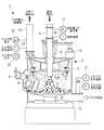
図1は、本発明を適用可能な石炭粉砕装置の一例を示す縦断面図である。この石炭粉砕装置1は、発電プラントのボイラに供給される微粉炭を生成する周知の構成を持つものであり、そのミル(粉砕部)2が中空の円筒形状をなすハウジング(筐体)3を備えている。このハウジング3の天頂中央部から石炭供給管4がハウジング3の内部に鉛直に突入するように装着され、その下端部がハウジング3の内部に開放されている。
Hereinafter, embodiments of the present invention will be described with reference to FIGS.
FIG. 1 is a longitudinal sectional view showing an example of a coal crusher to which the present invention can be applied. The coal pulverizing
ハウジング3内の下部には、石炭供給管4の開放口に対向して皿状の粉砕テーブル5が配置され、テーブル駆動機構6により回転駆動されるようになっている。そして、この粉砕テーブル5の上面の周縁部に対して離接可能に複数の粉砕ローラ7が配置されている。これらの粉砕ローラ7は支持装置8によって回転自在に支持されるとともに、押圧駆動装置9によって粉砕テーブル5に押し付けられている。
A dish-shaped crushing table 5 is disposed in the lower part of the
ハウジング3の内部において、石炭供給管4の周囲には遠心式の分級器11が回転自在に軸支され、ハウジング3の上部に設置された分級器駆動装置12によって回転駆動されるようになっている。分級器11の回転速度は後述する制御装置によって制御される。
Inside the
ハウジング3の、粉砕テーブル5よりも低い位置には一次空気供給管13が接続されている。この一次空気供給管13は、図示しない空気供給装置から供給される一次空気をハウジング3内に高速で供給する。この一次空気は、ボイラの排熱等と熱交換されて加熱された熱空気と、常温の冷空気とが所定の割合で混合された熱気であり、図示しない熱空気ダンパと冷空気ダンパの開度比によりハウジング3の内部温度が調整される。
A primary
また、ハウジング3の天頂部には出口管15が接続されている。この出口管15は図示しないボイラの火炉(バーナ)に通じている。
An
石炭供給管4は、図示しない石炭供給装置から粉砕テーブル5の上に石炭を供給する。石炭供給管4には、給炭量C1を計測する流量センサ17と、給炭温度を計測する温度センサ18とが設けられている。
また、一次空気供給管13には、一次空気の流量、即ちミル2の入口空気流量を計測する流量センサ20と、一次空気の温度、即ちミル2の入口空気温度を計測する温度センサ21とが設けられている。
さらに、出口管には、ミル2の出口圧力を計測する圧力センサ23と、ミル2の出口空気温度を計測する温度センサ24と、ミル2と火炉との差圧を計測する圧力センサ25とが設けられている。
The coal supply pipe 4 supplies coal onto the crushing table 5 from a coal supply device (not shown). The coal supply pipe 4 is provided with a
The primary
Further, the outlet pipe has a
このように構成された石炭粉砕装置1において、石炭供給管4から粉砕テーブル5の上に供給された石炭は、粉砕テーブル5の回転に伴う遠心力によって外周側に移動し、粉砕ローラ7と粉砕テーブル5との間に入り込んで粉砕される。この時、粉砕ローラ7は押圧駆動装置9によって粉砕テーブル5側に押圧されているために、粉砕テーブル5の回転に連動して回転する。
In the
石炭は粉砕ローラ7に粉砕されて微粉炭となり、粉砕テーブル5の下部の一次空気供給管13からミル2(ハウジング3)の内部に高速で流入する一次空気により上方に搬送され、分級器11によって粒度を分級される。そして、所定の粒径以下の微細な粒子のみが空気と共に出口管15からボイラの火炉に供給される。微細な粒子は着火性が良く、ボイラのバーナで効率良く燃焼することができる。一方、粒径の大きな粒子は分級器11の回転羽根ではじかれて粉砕テーブル5上に落下し、再び粉砕ローラ7により粉砕され、粒径をより小さくされて分級器11を経てボイラの火炉に供給される。
The coal is pulverized by the pulverizing
一次空気供給管13からミル2の内部に供給される一次空気は、前述のように、高温な熱空気と常温の冷空気とが所定の割合で混合された熱気であるため、ミル2の内部に給炭される石炭と、この石炭が粉砕されて生成された微粉炭とに含有されている水分を乾燥させることができる。石炭および微粉炭の水分率が高くなる程、熱空気ダンパの開度割合が大きくされて一次空気の温度が高くなるように制御される。
As described above, the primary air supplied from the primary
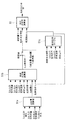
図2は、本発明の一実施形態に係る制御装置の構成を示すブロック図である。
この制御装置50は、ミル2の温度、好ましくは温度センサ24によって計測されるミル2の出口空気温度を制御するものであり、出炭水分率演算部51と、温度指令値補正部52と、先行信号演算部53とを具備して構成されている。
FIG. 2 is a block diagram illustrating a configuration of a control device according to an embodiment of the present invention.
The
出炭水分率演算部51は、ミル2における各種のプロセス値から、出炭される前記微粉炭の出炭水分率M2を演算する。ここで、各種のプロセス値としては、流量センサ20によって計測されるミル入口空気流量と、温度センサ21によって計測されるミル入口空気温度と、温度センサ24によって計測されるミル出口空気温度と、流量センサ17によって計測される石炭供給管4からの石炭の給炭量C1と、温度センサ18によって計測される給炭温度と、圧力センサ25によって計測されるミル2とボイラの火炉(非図示)との間の差圧と、圧力センサ23によって計測されるミル出口圧力、等を挙げることができる。
The coal output moisture
出炭水分率演算部51によって演算された出炭水分率M2は、目標となる出炭水分率設定値との差分55を算定され、この差分55が温度指令値補正部52によって給炭量C1の指令値に対するミル出口空気温度指令値(ミル温度指令値)への補正量となる。なお、関数発生部57において、ミル出口空気温度指令値と給炭量指令値との関係は、図2中のグラフ2Aに示すようになっている。温度指令値補正部52は、演算された出炭水分率M2の差分55のPID出力値を補正量として、関数発生部57において決定された補正前のミル出口空気温度指令値に加算し、これにより出炭水分率M2の状態に応じてミル出口空気温度指令値が補正される。
The coal output moisture rate M2 calculated by the coal output moisture
ところで、出炭水分率M2は、ミル2に給炭される石炭の水分率と、ミル2における乾燥効率ηとの相関関係から設定するのが好ましい。図2に示す出炭水分率演算部51においては、出炭水分率M2を求めるために、図3に示すような制御フローが実行される。
By the way, it is preferable to set the coal output moisture M2 from the correlation between the moisture content of coal fed to the
即ち、まず出炭量演算部51aにおいて、ミル火炉差圧と、ミル入口空気流量と、ミル出口空気温度と、ミル出口圧力とから、ミル2からの出炭量C2が演算される。要するに、ミル2に流入する空気と、ミル2から流出する空気との差圧から、流通する空気にどれだけの出炭量C2が含まれているかが演算される。
That is, first, the coal
次に、給炭水分率演算部51bにおいて給炭水分率M1が演算される。ここでは、火炉内の熱バランス(入熱と出熱の比率)から給炭の水分率が算出するべく、ミル入口空気流量と、ミル入口空気温度と、ミル出口空気温度と、給炭量C1と、給炭温度と、出炭量演算部51aにて演算された出炭量C2と、後述する乾燥効率ηとから給炭水分率M1が演算される。この給炭水分率M1の演算は、ミル2が静定中の条件下で行う必要がある。
Next, the coal supply moisture
さらに、乾燥効率テーブル51cにおいて乾燥効率ηが設定される。この乾燥効率テーブル51cは、給炭水分率演算部51bで演算された給炭水分率M1の値と、ミル入口空気流量と、ミル出口空気温度と、給炭量C1とをパラメータにして乾燥効率ηの仮定値が設定される。
Further, the drying efficiency η is set in the drying efficiency table 51c. The drying efficiency table 51c uses the values of the coal feed moisture percentage M1 calculated by the coal feed
そして、出炭水分率演算部51において、給炭水分率演算部51bで演算された給炭水分率M1と、乾燥効率テーブル51cで設定された乾燥効率ηの仮定値と、給炭量C1の値とから、出炭水分率M2が演算される。
Then, in the coal output moisture
上記の制御において、乾燥効率テーブル51cで設定された乾燥効率ηの仮定値は、給炭水分率演算部51bに代入されて給炭水分率M1の演算に用いられ、この給炭水分率演算部51bで演算された給炭水分率M1が再び乾燥効率テーブル51cに代入されて乾燥効率ηの仮定値が再設定され…、というルーティンが反復される。この反復演算は、ミル2の入口側の乾燥効率ηと出口側の乾燥効率ηとの差が所定の範囲内に収斂するまで繰り返される。このような反復演算を行うのは、給炭の水分率が定まらないと乾燥効率ηを算出できないためである。
In the above control, the assumed value of the drying efficiency η set in the drying efficiency table 51c is substituted into the coal supply moisture
このように、ミル2に給炭される石炭の水分率M1と、ミル2における乾燥効率ηとの相関関係を踏まえて出炭水分率M2を演算することにより、ミル2から出炭される微粉炭の水分率M2を正確に算出することができる。
Thus, by calculating the coal output moisture content M2 based on the correlation between the moisture content M1 of coal supplied to the
ここまでの制御によれば、ミル2に給炭される石炭の水分率M1が高い場合であっても、それに応じてミル2の内部温度が高められ、ミル2内に給炭される石炭および粉砕された微粉炭の乾燥が促進され、発電機の負荷が変動する場合における応答性をある程度まで改善することができる。
According to the control so far, even when the moisture content M1 of the coal fed to the
さらに、図2に示すように、発電機の負荷が変動する時には、先行信号演算部53において出炭水分率M2から求められた温度制御の先行信号Sが、補正後のミル出口空気温度指令値に付加され、このミル出口空気温度指令値がさらに補正される。先行信号演算部53には、発電機負荷と、発電機負荷指令の変化幅および変化率と、出炭水分率演算部51において演算された出炭水分率M2とが代入され、先行信号Sが演算される。
Further, as shown in FIG. 2, when the load on the generator fluctuates, the preceding signal S of the temperature control obtained from the coal output moisture rate M2 in the preceding
図2中のグラフ2Bに示すように、先行信号演算部53は、発電機の負荷変化幅Haが大きい程、先行信号Sの変化幅Hbを大きく設定する。また、先行信号演算部53は、発電機の負荷変化率Raが大きい程、先行信号Sの上げ側変化率Rbを大きく設定する。つまり、上げ側変化率Rbの傾斜を急角度に設定する。なお、下げ側変化率Rcについては、上げ側変化率Rbのような急角度にする必要は特にない。また、上げ側変化率Rbから下げ側変化率Rcに移行する間には所定の保持時間が設けられる。
As shown in the graph 2B in FIG. 2, the preceding
図4は、先行信号演算部53における先行信号Sの求め方を示す制御フロー図である。先行信号演算部53には5つの関数発生部53a〜53eが設けられている。まず、関数発生部53aにおいて、グラフ4Aに示すように、発電機負荷帯(50%,60%,70%…等)に応じて、ベースとなる補正量の曲線が関数として設定される。そして、発電機負荷の上げ幅(負荷変化幅Ha)が大きい程、ミル出口空気温度の上昇幅が大きくなるように先行信号Sの変化幅Hbが大きく設定される。
FIG. 4 is a control flow diagram showing how to obtain the preceding signal S in the preceding
また、関数発生部53bにおいては、グラフ4Bに示すように、発電機の負荷変化率Raが大きくなる程(傾斜が急になる程)、先行信号Sの変化率、特にここでは上げ側変化率Rb(図2参照)が大きくなるように(傾斜が急になるように)演算係数に設定される。
Further, in the
さらに、関数発生部53cにおいては、グラフ4Cに示すように、出炭水分率M2が高くなる程、先行信号Sの変化幅Hbが大きくなるように演算係数が設定される。
Further, in the
また、関数発生部53dにおいては、グラフ4Dに示すように、出炭水分率M2が高くなる程、先行信号Sの温度上げ側の変化率のレートリミットが大きく設定され、関数発生部53eにおいては、グラフ4Eに示すように、出炭水分率M2が高くなる程、先行信号Sの温度下げ側の変化率のレートリミットが大きく設定される。
Moreover, in the
制御装置50は以上のように構成されている。
上記の説明の通り、この制御装置50は、ミル2における各種のプロセス値から、出炭される微粉炭の出炭水分率M2を演算する出炭水分率演算部51と、この出炭水分率M2のPID出力値を補正量としてミル2へのミル温度指令値に加算することにより、該ミル温度指令値を出炭水分率M2の状態により調整する温度指令値補正部52と、発電機の負荷変動時に、出炭水分率M2から求めた温度制御の先行信号Sをミル温度指令値に付加し、該ミル温度指令値を補正する先行信号演算部53と、を具備している。
The
As described above, the
そして、発電機の負荷変動時には、先行信号演算部53において、出炭水分率M2から求めた温度制御の先行信号Sがミル温度指令値に付加され、ミル温度指令値が補正される。
When the load on the generator fluctuates, the preceding
このため、例えばミル2に給炭される石炭の水分率が高い時に発電機負荷を高める運転状況になっても、先行信号演算部53が温度制御の先行信号Sをミル温度指令値に付加することにより、実際の出炭タイミングに先行してミル2の出口空気温度が上昇制御され、給炭される石炭および粉砕された微粉炭の乾燥が促進される。したがって、発電機の負荷上昇に合わせて出炭量C2を増加する場合の応答性を飛躍的に改善することができる。
For this reason, for example, even if it becomes the driving | running condition which raises a generator load when the moisture content of the coal supplied to the
また、この制御装置50において、先行信号演算部53は、発電機の負荷変化幅Haが大きい程、先行信号Sの変化幅Hbを大きく設定するため、ミル2の出口空気温度の上げ幅を予め大きくすることにより、負荷変化幅Haが大きい場合に、ミル2での乾燥をより早めて出炭量の応答遅れを低減させ、負荷追従性を改善することができる。
In this
さらに、先行信号演算部53は、発電機の負荷変化幅Haが大きい程、先行信号Sの上げ側変化率を大きく設定するため、負荷変化幅Haに応じて予めミル2の出口空気温度の上げ幅を大きくすることにより、負荷変化幅Haが大きい場合に、ミル2での乾燥をより早めて出炭量の応答遅れを低減させ、負荷追従性を改善することができる。
Furthermore, since the preceding
また、先行信号演算部53は、出炭水分率M2が高くなる程、先行信号Sの変化幅を大きく設定するため、出炭水分率M2に応じて予めミル2の出口空気温度の上げ幅を大きくし、出炭水分率M2が大きい場合のミル2での乾燥遅れを低減させることにより、出炭量の応答遅れを低減させ、負荷追従性を改善することができる。
Moreover, since the preceding
さらにまた、先行信号演算部53は、出炭水分率M2が高くなる程、先行信号Sの変化率のレートリミットを大きく設定するため、出炭水分率M2に応じて予めミル2の出口空気温度を上げる速度を速め、出炭水分率M2が大きい場合のミル2での乾燥遅れを低減させることにより、出炭量の応答遅れを低減させ、負荷追従性を改善することができる。
Furthermore, since the preceding
また、この制御装置50において、ミル2から出炭される微粉炭の出炭水分率M2は、ミル2に給炭される石炭の水分率と、ミル2における乾燥効率ηとの相関関係から演算されるため、出炭水分率M2を正確に算出し、先行信号演算部53において演算される先行信号Sの値を最適化して出炭応答性を向上させることができる。
Further, in this
こうして、本発明に係る石炭粉砕装置の制御装置および制御方法によれば、ミル2に給炭される石炭の水分率に拘わらず、発電機の負荷上昇に合わせて出炭量C2を増加する場合の応答性を改善することができる。
Thus, according to the control device and the control method of the coal pulverizer according to the present invention, regardless of the moisture content of the coal supplied to the
なお、本発明は上記実施形態の構成のみに限定されるものではなく、本発明の要旨を逸脱しない範囲内において適宜変更や改良を加えることができ、このように変更や改良を加えた実施形態も本発明の権利範囲に含まれるものとする。 It should be noted that the present invention is not limited to the configuration of the above-described embodiment, and can be appropriately modified or improved within a scope not departing from the gist of the present invention. Are also included in the scope of rights of the present invention.
例えば、上記実施形態においては、先行信号Sによってミル2の出口空気温度が先行調整されるように説明されているが、ミル2の入口空気温度やミル2の入口空気流量を先行調整するようにしてもよい。
For example, in the above embodiment, it has been described that the outlet air temperature of the
1 石炭粉砕装置
2 ミル
50 制御装置
51 出炭水分率演算部
52 温度指令値補正部
53 先行信号演算部
Ha 発電機の負荷変化幅
Hb 先行信号の変化幅
M1 給炭水分率
M2 出炭水分率
Ra 発電機の負荷変化率
Rb 先行信号の上げ側変化率
Rc 先行信号の下げ側変化率
S 先行信号
η ミルにおける乾燥効率
DESCRIPTION OF
Claims (7)
前記ミルにおける各種のプロセス値から、出炭される前記微粉炭の出炭水分率を演算する出炭水分率演算部と、
前記出炭水分率のPID出力値を補正量として前記ミルへのミル温度指令値に加算することにより、該ミル温度指令値を前記出炭水分率の状態により調整する温度指令値補正部と、
前記発電機の負荷変動時に、前記出炭水分率から求めた温度制御の先行信号を前記ミル温度指令値に付加し、該ミル温度指令値を補正する先行信号演算部と、
を具備してなることを特徴とする石炭粉砕装置の制御装置。 A pulverized coal produced by pulverizing coal with a mill is provided in a coal pulverization device that outputs to a boiler that generates steam for driving a generator, and is a control device for a coal pulverization device that controls the temperature of the mill. ,
From various process values in the mill, a coal output moisture rate calculating unit for calculating the coal output moisture rate of the pulverized coal to be output,
A temperature command value correction unit that adjusts the mill temperature command value according to the state of the coal output moisture rate by adding the PID output value of the coal output moisture rate as a correction amount to the mill temperature command value to the mill;
At the time of load fluctuation of the generator, a preceding signal for temperature control obtained from the coal output moisture content is added to the mill temperature command value, and a preceding signal calculation unit for correcting the mill temperature command value;
The control apparatus of the coal grinding | pulverization apparatus characterized by comprising.
前記ミルにおける各種のプロセス値から、出炭される前記微粉炭の出炭水分率を演算し、
前記出炭水分率のPID出力値を補正量として前記ミルへのミル温度指令値に加算することにより、該ミル温度指令値を前記出炭水分率の状態により調整するとともに、
前記発電機の負荷変動時に、前記出炭水分率から求めた温度制御の先行信号を前記ミル温度指令値に付加して該ミル温度指令値を補正する、
ことを特徴とする石炭粉砕装置の制御方法。 A control method for a coal pulverizer for controlling the temperature of the mill, which is provided in a coal pulverizer that outputs pulverized coal produced by pulverizing coal with a mill to a boiler that generates steam for driving a generator. ,
From various process values in the mill, calculate the coal moisture content of the pulverized coal to be discharged,
By adding the PID output value of the coal output moisture content as a correction amount to the mill temperature command value to the mill, the mill temperature command value is adjusted according to the state of the coal output moisture content,
At the time of load fluctuation of the generator, a preceding signal for temperature control obtained from the coal output moisture content is added to the mill temperature command value to correct the mill temperature command value.
A control method for a coal pulverizer.
Priority Applications (1)
| Application Number | Priority Date | Filing Date | Title |
|---|---|---|---|
| JP2012274854A JP2014117657A (en) | 2012-12-17 | 2012-12-17 | Control device of coal crusher, and control method thereof |
Applications Claiming Priority (1)
| Application Number | Priority Date | Filing Date | Title |
|---|---|---|---|
| JP2012274854A JP2014117657A (en) | 2012-12-17 | 2012-12-17 | Control device of coal crusher, and control method thereof |
Publications (1)
| Publication Number | Publication Date |
|---|---|
| JP2014117657A true JP2014117657A (en) | 2014-06-30 |
Family
ID=51173004
Family Applications (1)
| Application Number | Title | Priority Date | Filing Date |
|---|---|---|---|
| JP2012274854A Pending JP2014117657A (en) | 2012-12-17 | 2012-12-17 | Control device of coal crusher, and control method thereof |
Country Status (1)
| Country | Link |
|---|---|
| JP (1) | JP2014117657A (en) |
Cited By (9)
| Publication number | Priority date | Publication date | Assignee | Title |
|---|---|---|---|---|
| JP2015105812A (en) * | 2013-12-02 | 2015-06-08 | 三菱日立パワーシステムズ株式会社 | Apparatus and method for pulverizing solid fuel |
| CN105268536A (en) * | 2015-11-03 | 2016-01-27 | 西安交通大学 | Self-adaption online corrected thermal power plant ball mill load soft measurement method |
| CN105289830A (en) * | 2015-11-30 | 2016-02-03 | 上海明华电力技术工程有限公司 | Medium-speed coal mill start-stop control method based on online coal quantity compensation |
| CN105903544A (en) * | 2016-04-28 | 2016-08-31 | 韦国思 | Coal mill water resistor polar plate guide structure |
| JP2016183839A (en) * | 2015-03-26 | 2016-10-20 | 一般財団法人電力中央研究所 | Pulverized coal firing boiler and power generation facility |
| CN106123005A (en) * | 2016-06-23 | 2016-11-16 | 国网新疆电力公司电力科学研究院 | The coal-supplying amount pre-control method of coal unit boiler feed-forward |
| JP2017202472A (en) * | 2016-05-13 | 2017-11-16 | 三菱日立パワーシステムズ株式会社 | Coal crushing device, apparatus and method for controlling the device, and thermal power generation plant by coal ignition |
| CN109013032A (en) * | 2017-10-27 | 2018-12-18 | 江西理工大学 | A kind of method of source signal fusion forecasting ball mill filling rate, material ball ratio |
| CN113019668A (en) * | 2021-03-17 | 2021-06-25 | 华北电力科学研究院有限责任公司 | Powder making system starting control method and device |
-
2012
- 2012-12-17 JP JP2012274854A patent/JP2014117657A/en active Pending
Cited By (11)
| Publication number | Priority date | Publication date | Assignee | Title |
|---|---|---|---|---|
| JP2015105812A (en) * | 2013-12-02 | 2015-06-08 | 三菱日立パワーシステムズ株式会社 | Apparatus and method for pulverizing solid fuel |
| JP2016183839A (en) * | 2015-03-26 | 2016-10-20 | 一般財団法人電力中央研究所 | Pulverized coal firing boiler and power generation facility |
| CN105268536A (en) * | 2015-11-03 | 2016-01-27 | 西安交通大学 | Self-adaption online corrected thermal power plant ball mill load soft measurement method |
| CN105289830A (en) * | 2015-11-30 | 2016-02-03 | 上海明华电力技术工程有限公司 | Medium-speed coal mill start-stop control method based on online coal quantity compensation |
| CN105289830B (en) * | 2015-11-30 | 2018-07-03 | 上海明华电力技术工程有限公司 | A kind of medium-speed pulverizer start-up and shut-down control method based on coal amount online compensation |
| CN105903544A (en) * | 2016-04-28 | 2016-08-31 | 韦国思 | Coal mill water resistor polar plate guide structure |
| JP2017202472A (en) * | 2016-05-13 | 2017-11-16 | 三菱日立パワーシステムズ株式会社 | Coal crushing device, apparatus and method for controlling the device, and thermal power generation plant by coal ignition |
| CN106123005A (en) * | 2016-06-23 | 2016-11-16 | 国网新疆电力公司电力科学研究院 | The coal-supplying amount pre-control method of coal unit boiler feed-forward |
| CN109013032A (en) * | 2017-10-27 | 2018-12-18 | 江西理工大学 | A kind of method of source signal fusion forecasting ball mill filling rate, material ball ratio |
| CN113019668A (en) * | 2021-03-17 | 2021-06-25 | 华北电力科学研究院有限责任公司 | Powder making system starting control method and device |
| CN113019668B (en) * | 2021-03-17 | 2022-12-23 | 华北电力科学研究院有限责任公司 | Powder making system starting control method and device |
Similar Documents
| Publication | Publication Date | Title |
|---|---|---|
| JP2014117657A (en) | Control device of coal crusher, and control method thereof | |
| JP7039805B2 (en) | Solid fuel crusher | |
| JP6225217B1 (en) | Coal crusher, control device and control method thereof, and coal-fired thermal power plant | |
| JP4801552B2 (en) | Biomass crusher and control method thereof | |
| JP5594941B2 (en) | Biomass crusher and control method of the apparatus | |
| JP6599259B2 (en) | Solid fuel pulverizer and control method thereof | |
| WO2010084156A1 (en) | Method for producing pulverized coal | |
| CN107262261A (en) | A kind of coal pulverizer air quantity control method for adapting to fired power generating unit Ultra-low load operation | |
| JP2015001347A (en) | Vertical grinding classifier | |
| JP6500305B2 (en) | Method of producing carbide and carbide producing apparatus | |
| CN109622149B (en) | Solid fuel pulverizing system, control method thereof, and solid fuel pulverizing apparatus | |
| JP7362253B2 (en) | Solid fuel pulverizer, power plant equipped with the same, and method for controlling the solid fuel pulverizer | |
| JP6319594B2 (en) | Coal feed amount control method and apparatus for coal crushing mill | |
| JP2744019B2 (en) | Vertical mill control device | |
| JP6195512B2 (en) | Solid fuel pulverization apparatus and solid fuel pulverization method | |
| WO2019004096A1 (en) | Vertical roller mill and operation method therefor | |
| JP7341669B2 (en) | Solid fuel crushing device, power plant equipped with the same, and solid fuel crushing method | |
| JP2021085634A (en) | Solid fuel crushing system and electric power generating plant comprising the same as well as control method for solid fuel crushing system | |
| JPH04244246A (en) | Roller mill apparatus | |
| JP2023107454A (en) | Solid fuel crushing apparatus, and control method for solid fuel crushing apparatus | |
| JP6104791B2 (en) | Solid fuel pulverizer and control method of solid fuel pulverizer | |
| JPH1085624A (en) | Controller for vertical mill | |
| CN204373345U (en) | A kind of tunnel type slurry drying oven tailored flour crushing device | |
| JP2022041974A (en) | Device, power generating plant, device control method, program, power generating plant system, and control method of power generating plant system | |
| JP2000171027A (en) | Load variation rate controller and control method for coal burning thermal power plant |