JP2014113902A - Mode switching control system of hybrid vehicle - Google Patents
Mode switching control system of hybrid vehicle Download PDFInfo
- Publication number
- JP2014113902A JP2014113902A JP2012268994A JP2012268994A JP2014113902A JP 2014113902 A JP2014113902 A JP 2014113902A JP 2012268994 A JP2012268994 A JP 2012268994A JP 2012268994 A JP2012268994 A JP 2012268994A JP 2014113902 A JP2014113902 A JP 2014113902A
- Authority
- JP
- Japan
- Prior art keywords
- mode switching
- clutch
- switching control
- control device
- hybrid vehicle
- Prior art date
- Legal status (The legal status is an assumption and is not a legal conclusion. Google has not performed a legal analysis and makes no representation as to the accuracy of the status listed.)
- Pending
Links
Images


Classifications
-
- Y—GENERAL TAGGING OF NEW TECHNOLOGICAL DEVELOPMENTS; GENERAL TAGGING OF CROSS-SECTIONAL TECHNOLOGIES SPANNING OVER SEVERAL SECTIONS OF THE IPC; TECHNICAL SUBJECTS COVERED BY FORMER USPC CROSS-REFERENCE ART COLLECTIONS [XRACs] AND DIGESTS
- Y02—TECHNOLOGIES OR APPLICATIONS FOR MITIGATION OR ADAPTATION AGAINST CLIMATE CHANGE
- Y02T—CLIMATE CHANGE MITIGATION TECHNOLOGIES RELATED TO TRANSPORTATION
- Y02T10/00—Road transport of goods or passengers
- Y02T10/60—Other road transportation technologies with climate change mitigation effect
- Y02T10/62—Hybrid vehicles
Abstract
Description
本発明は、エンジンおよび電動モータを動力源として搭載され、電動モータのみにより走行する電気走行モード(EVモード)と、電動モータおよびエンジンにより走行するハイブリッド走行モード(HEVモード)とを選択可能なハイブリッド車両のモード切り替え制御装置に関するものである。 The present invention is a hybrid equipped with an engine and an electric motor as a power source and capable of selecting an electric travel mode (EV mode) that travels only by the electric motor and a hybrid travel mode (HEV mode) that travels by the electric motor and engine. The present invention relates to a vehicle mode switching control device.
このようなハイブリッド車両としては従来、例えば特許文献1に記載のようなものが知られている。
このハイブリッド車両は、一方の動力源であるエンジンが無段変速機およびクラッチを順次介して車輪に切り離し可能に駆動結合され、他方の動力源である電動モータが当該車輪に常時結合された型式のものである。
As such a hybrid vehicle, a vehicle as described in
This hybrid vehicle is of a type in which an engine that is one power source is drivably coupled to a wheel through a continuously variable transmission and a clutch sequentially, and an electric motor that is the other power source is always coupled to the wheel. Is.
かかるハイブリッド車両は、エンジンを停止すると共に上記のクラッチを解放することで電動モータのみによるEVモードでの電気走行(EV走行)が可能であり、エンジンを始動させると共に当該クラッチを締結することにより電動モータおよびエンジンによるHEVモードでのハイブリッド走行(HEV走行)が可能である。 Such a hybrid vehicle is capable of electric travel (EV travel) in the EV mode using only the electric motor by stopping the engine and releasing the clutch, and is electrically operated by starting the engine and engaging the clutch. Hybrid running (HEV running) in HEV mode with a motor and engine is possible.
なお、EV走行中にクラッチを上記のごとく解放することで、停止状態のエンジンが(変速機が存在している場合は変速機も)車輪から切り離されていることとなり、当該エンジン(変速機)をEV走行中に連れ回す(引き摺る)ことがなく、その分のエネルギー損失を回避し得てエネルギー効率を高めることができる。 By releasing the clutch as described above during EV travel, the engine in the stopped state (and the transmission if a transmission is present) is disconnected from the wheel, and the engine (transmission) Can be avoided during the EV travel, energy loss can be avoided and energy efficiency can be increased.
上記ハイブリッド車両にあっては、HEV走行中にアクセルペダルを釈放してコースティング(惰性)走行へ移行した場合、エンジンを停止すると共にクラッチを解放してHEV走行モードからEV走行モードに切り替わり、EV走行中にアクセルペダルを踏み込む再加速操作(発進を含む)が行われた場合、エンジンを再始動すると共にクラッチを締結してEV走行モードからHEV走行モードに切り替わる。 In the above hybrid vehicle, when the accelerator pedal is released during HEV driving and the coasting (inertia) driving is started, the engine is stopped and the clutch is released to switch from HEV driving mode to EV driving mode. When a re-acceleration operation (including starting) is performed by depressing the accelerator pedal during traveling, the engine is restarted and the clutch is engaged to switch from the EV traveling mode to the HEV traveling mode.
ところで上記の発進を含む再加速時は、大きな車輪駆動力(トルク)が必要であることから、無段変速機が変速比をできるだけロー側変速比にされている必要がある。
しかし特許文献1所載のハイブリッド車両は、エンジンを停止すると共にクラッチを解放させて行うHEV→EVモード切り替え時における無段変速機の変速制御について何ら考慮しておらず、無段変速機の変速はハードウエアの成り行きに任せて行われると考えるのが妥当である。
By the way, at the time of reacceleration including the above-described start, a large wheel driving force (torque) is required, and therefore the continuously variable transmission needs to have a gear ratio as low as possible.
However, the hybrid vehicle described in
ここで、HEV→EVモード切り替え時における無段変速機の成り行き変速について考察する。
当該モード切り替えはエンジンを停止すると共にクラッチを解放させることによって遂行するため、そして自動変速機の変速制御がクラッチの締結制御と共に、エンジン駆動されるポンプからの作動油を媒体として行われることから、HEV→EVモード切り替え時に無段変速機は変速不能となり、当該モード切り替え時の変速比のままにされる。
Here, consideration will be given to the actual shifting of the continuously variable transmission when the HEV → EV mode is switched.
Since the mode switching is performed by stopping the engine and releasing the clutch, and the shift control of the automatic transmission is performed using the hydraulic oil from the pump driven by the engine together with the clutch engagement control, When the HEV → EV mode is switched, the continuously variable transmission becomes impossible to shift, and the gear ratio at the time of the mode switching remains unchanged.
よって従来のハイブリッド車両は、HEV→EVモード切り替え後の発進を含む再加速時に無段変速機がロー側変速比選択状態であることがほとんどなく、ハイ側変速比での再加速を余儀なくされて、駆動力不足により再加速(再発進)性能が悪くなるという問題を生ずる虞があった。 Therefore, in the conventional hybrid vehicle, the continuously variable transmission is rarely in the low gear ratio selection state at the time of reacceleration including the start after switching from HEV to EV mode, and re-acceleration at the high gear ratio is forced. There is a concern that the re-acceleration (restart) performance may deteriorate due to insufficient driving force.
ところで上記したハイブリッド車両にあっては、HEV→EVモード切り替え要求(例えばブレーキ操作)が頻繁に発生したり消失するような状況下で、クラッチの繰り返し締結(エンジンの繰り返し始動)によりエンジンスタータモータの耐久性が低下されるのを防止しつつ、EV回生によるエネルギー効率を高めるなどのため、
HEV→EVモード切り替え要求(ブレーキ操作)が発生したことのみをもって、つまりHEV→EVモード切り替えに際し必要なクラッチの解放を許可すべき運転状態(ブレーキ操作状態)になったことのみをもって当該クラッチの解放を行うのではなく、この運転状態が設定時間に亘って継続した時にはじめて当該HEV→EVモード切り替え用のクラッチ解放(エンジン停止)を実行させるように成すのがよい。
By the way, in the hybrid vehicle described above, the engine starter motor is switched by repeatedly engaging the clutch (repeating the engine) in a situation where the HEV → EV mode switching request (for example, brake operation) frequently occurs or disappears. To increase the energy efficiency of EV regeneration while preventing the durability from decreasing,
The clutch is released only when a HEV → EV mode switching request (brake operation) is generated, that is, only when an operation state (brake operation state) that should permit the release of the clutch necessary for switching the HEV → EV mode is entered. It is preferable that the clutch release (engine stop) for switching the HEV → EV mode is executed only when the operation state continues for the set time.
本発明は、この場合上記の設定時間中クラッチが未だ締結されていて(エンジンが運転されていて)、無段変速機の変速制御が可能であるとの観点から、この設定時間中に無段変速機を強制的にダウンシフトさせることにより、ハイ側変速比での再加速(再発進)を回避して、駆動力不足による再加速(再発進)性能の悪化を防止し得るようにしたハイブリッド車両の(HEV→EV)モード切り替え制御装置を提案することを目的とする。 In this case, according to the present invention, from the viewpoint that the clutch is still engaged during the set time (the engine is operated) and the speed change control of the continuously variable transmission is possible, the continuously variable during the set time. A hybrid that forcibly downshifts the transmission to avoid re-acceleration (restart) at the high gear ratio and to prevent deterioration of re-acceleration (restart) performance due to insufficient driving force The purpose is to propose a vehicle (HEV → EV) mode switching control device.
この目的のため、本発明によるハイブリッド車両のモード切り替え制御装置は、これを以下のごとくに構成する。 For this purpose, the hybrid vehicle mode switching control apparatus according to the present invention is configured as follows.
先ず本発明の前提となるハイブリッド車両を説明するに、これは、
動力源としてエンジンのほかに電動モータを具え、前記エンジンが、該エンジンにより駆動されるポンプからの流体を媒体としてそれぞれ制御される無段変速機およびクラッチを順次介して車輪に切り離し可能に駆動結合され、該クラッチを解放すると共に前記エンジンを停止させることにより前記電動モータのみにより走行される電気走行モードを選択可能であるほか、前記エンジンを始動させると共に前記クラッチを締結することにより前記電動モータおよびエンジンにより走行されるハイブリッド走行モードを選択可能な車両である。
First, to explain the hybrid vehicle which is the premise of the present invention,
In addition to the engine as a power source, an electric motor is provided, and the engine is operatively coupled to the wheels through a continuously variable transmission and a clutch that are controlled by a fluid from a pump driven by the engine as a medium. In addition to releasing the clutch and stopping the engine, it is possible to select an electric travel mode in which the vehicle travels only by the electric motor, and by starting the engine and engaging the clutch, the electric motor and The vehicle is capable of selecting a hybrid travel mode traveled by an engine.
本発明のモード切り替え制御装置は、かかる車両に対し、以下のごときクラッチ解放許可判定手段と、モード切り替え手段と、強制ダウンシフト手段とを設けた構成に特徴づけられる。 The mode switching control device of the present invention is characterized by a configuration in which clutch release permission determining means, mode switching means, and forced downshift means are provided for such a vehicle as follows.
クラッチ解放許可判定手段は、上記ハイブリッド走行モードで、上記電気走行モードへの切り替えに際して必要な前記クラッチの解放を許可すべきクラッチ解放許可運転になったか否かを判定するものである。
モード切り替え手段は、上記クラッチ解放許可判定手段で上記クラッチ解放許可運転になったと判定された後、該クラッチの解放を許可すべきでないクラッチ解放不許可運転に戻らなかったのを確認した時、上記クラッチの解放を実行して上記ハイブリッド走行モードから電気走行モードへの切り替えを行うものである。
強制ダウンシフト手段は、上記クラッチ解放不許可運転へ戻らなかったのを確認するための時間中に上記無段変速機を強制的にロー側変速比に向けてダウンシフトさせるものである。
The clutch release permission determining means determines whether or not a clutch release permission operation for permitting release of the clutch necessary for switching to the electric travel mode has been performed in the hybrid travel mode.
When it is determined that the clutch release permission determination means has made the clutch release permission operation, the mode switching means confirms that the clutch release permission operation that should not be permitted to release the clutch has not returned to the clutch release permission operation. The clutch is released to switch from the hybrid travel mode to the electric travel mode.
The forced downshift means forcibly downshifts the continuously variable transmission toward the low gear ratio during a time period for confirming that the operation has not been returned to the clutch release disapproval operation.
本発明によるハイブリッド車両のモード切り替え制御装置にあっては、
先ずハイブリッド走行モードから電気走行モードへの切り替えに際して必要なクラッチの解放を許可すべきクラッチ解放許可運転になった後、該クラッチの解放を許可すべきでないクラッチ解放不許可運転に戻らなかったのを確認した時、はじめて該クラッチの解放を実行してハイブリッド走行モードから電気走行モードへの切り替えを実行するため、
例えば、ハイブリッド走行モードから電気走行モードへのモード切り替え要求が頻繁に発生したり消失するような状況下でも、クラッチの繰り返し締結(エンジンの繰り返し始動)が起きることがなくて、例えばエンジンスタータモータの耐久性が低下されるのを防止しつつ、電気走行モードでの回生によるエネルギー効率を高めるというような要求を実現することができる。
In the hybrid vehicle mode switching control device according to the present invention,
First, after switching to the clutch release permission operation that should allow the release of the clutch required when switching from the hybrid travel mode to the electric travel mode, the clutch release permission operation that should not allow the clutch release was not returned to When confirming, to release the clutch for the first time and to switch from the hybrid travel mode to the electric travel mode,
For example, even when a mode switching request from the hybrid travel mode to the electric travel mode frequently occurs or disappears, the clutch is not repeatedly engaged (repeated engine start). While preventing the durability from being lowered, it is possible to realize a demand to increase energy efficiency by regeneration in the electric travel mode.
更に本発明では、かかる作用効果を達成するために設定されている上記の時間、つまりクラッチ解放不許可運転に戻らなかったのを確認するための時間を有効利用して、この時間中に無段変速機を強制的にロー側変速比に向けて強制的にダウンシフトさせるため、
ハイブリッド走行モードから電気走行モードへのモード切り替え後の発進を含む再加速時に無段変速機がロー側変速比選択状態にされていることとなり、当該発進を含む再加速がロー側変速比選択状態で開始され、駆動力不足により再加速(再発進)性能が悪くなるという前記の問題を解消することができる。
Further, in the present invention, the above-mentioned time set for achieving such an effect, that is, the time for confirming that the operation has not been returned to the clutch release disapproval operation is effectively used, and during this time, steplessly. To forcibly downshift the transmission toward the low gear ratio,
At the time of re-acceleration including the start after switching from the hybrid travel mode to the electric travel mode, the continuously variable transmission is in the low gear ratio selection state, and the re-acceleration including the start is in the low gear ratio selection state. The above-described problem that the reacceleration (restart) performance is deteriorated due to insufficient driving force can be solved.
以下、本発明の実施の形態を、図面に示す実施例に基づき詳細に説明する。
<第1実施例の構成>
図1は、本発明の第1実施例になるモード切り替え制御装置を具えたハイブリッド車両の駆動系およびその全体制御システムを示す概略系統図である。
Hereinafter, embodiments of the present invention will be described in detail based on examples shown in the drawings.
<Configuration of the first embodiment>
FIG. 1 is a schematic system diagram illustrating a drive system of a hybrid vehicle including a mode switching control device according to a first embodiment of the present invention and an overall control system thereof.
図1のハイブリッド車両は、エンジン1および電動モータ2を動力源として搭載され、エンジン1は、スタータモータ3により始動する。
エンジン1は、Vベルト式無段変速機4を介して駆動車輪5に適宜切り離し可能に駆動結合し、Vベルト式無段変速機4は、概略を以下に説明するようなものとする。
The hybrid vehicle in FIG. 1 is mounted with an
The
Vベルト式無段変速機4は、プライマリプーリ6と、セカンダリプーリ7と、これらプーリ6,7間に掛け渡したVベルト8とからなる無段変速機構CVTを主たる構成要素とする。
プライマリプーリ6はトルクコンバータT/Cを介してエンジン1のクランクシャフトに結合し、セカンダリプーリ7はクラッチCLおよびファイナルギヤ組9を順次介して駆動車輪5に結合する。
The V-belt type continuously
The
かくしてクラッチCLの締結状態で、エンジン1からの動力はトルクコンバータT/Cを経てプライマリプーリ6へ入力され、その後Vベルト8、セカンダリプーリ7、クラッチCLおよびファイナルギヤ組9を順次経て駆動車輪5に達し、ハイブリッド車両の走行に供される。
Thus, with the clutch CL engaged, the power from the
かかるエンジン動力伝達中、プライマリプーリ6のプーリV溝幅を小さくしつつ、セカンダリプーリ7のプーリV溝幅を大きくすることで、Vベルト8がプライマリプーリ6との巻き掛け円弧径を大きくされると同時にセカンダリプーリ7との巻き掛け円弧径を小さくされ、Vベルト式無段変速機4はハイ側プーリ比(ハイ側変速比)へのアップシフトを行うことができる。
逆にプライマリプーリ6のプーリV溝幅を大きくしつつ、セカンダリプーリ7のプーリV溝幅を小さくすることで、Vベルト8がプライマリプーリ6との巻き掛け円弧径を小さくされると同時にセカンダリプーリ7との巻き掛け円弧径を大きくされ、Vベルト式無段変速機4はロー側プーリ比(ロー側変速比)へのダウンシフトを行うことができる。
During the transmission of the engine power, the pulley V groove width of the
Conversely, by increasing the pulley V groove width of the
電動モータ2はファイナルギヤ組11を介して駆動車輪5に常時結合し、この電動モータ2は、バッテリ12の電力によりインバータ13を介して駆動する。
インバータ13は、バッテリ12の直流電力を交流電力に変換して電動モータ2へ供給すると共に、電動モータ2への供給電力を加減することにより、電動モータ2を駆動力制御および回転方向制御する。
The
The
なお電動モータ2は、上記のモータ駆動のほかに発電機としても機能し、後で詳述する回生制動の用にも供する。
この回生制動時はインバータ13が、電動モータ2に回生制動力分の発電負荷をかけることにより、電動モータ2を発電機として作用させ、電動モータ2の発電電力をバッテリ12に蓄電する。
The
During this regenerative braking, the
図1につき上記した駆動系を具えるハイブリッド車両は、クラッチCLを解放すると共にエンジン1を停止させた状態で、電動モータ2を駆動すると、電動モータ2の動力のみがファイナルギヤ組11を経て駆動車輪5に達し、ハイブリッド車両は電動モータ2のみによる電気走行モード(EVモード)で走行を行うことができる。
この間、クラッチCLを解放していることで、停止状態のエンジン1を連れ回すことがなく、EV走行中の無駄な電力消費を抑制することができる。
In the hybrid vehicle having the drive system described above with reference to FIG. 1, when the
During this time, by disengaging the clutch CL, it is possible to suppress wasteful power consumption during EV traveling without causing the stopped
上記のEV走行状態においてエンジン1をスタータモータ3により始動させると共にクラッチCLを締結させると、エンジン1からの動力がトルクコンバータT/C、プライマリプーリ6、Vベルト8、セカンダリプーリ7、クラッチCLおよびファイナルギヤ組9を順次経て駆動車輪5に達するようになり、ハイブリッド車両はエンジン1および電動モータ2によるハイブリッド走行モード(HEVモード)で走行を行うことができる。
When the
ハイブリッド車両を上記の走行状態から停車させたり、この停車状態に保つに際しては、駆動車輪5と共に回転するブレーキディスク14をキャリパ15により挟圧して制動することで目的を達する。
キャリパ15は、運転者が踏み込むブレーキペダル16の踏力に応動して負圧式ブレーキブースタ17による倍力下でブレーキペダル踏力対応のブレーキ液圧を出力するマスターシリンダ18に接続し、このブレーキ液圧でキャリパ15を作動させてブレーキディスク14の制動を行う。
When the hybrid vehicle is stopped from the above running state or kept in this stopped state, the
The
ハイブリッド車両はEVモードおよびHEVモードのいずれにおいても、運転者がアクセルペダル19を踏み込んで指令する駆動力指令に応じたトルクで車輪5を駆動され、運転者の要求に応じた駆動力をもって走行される。
In both the EV mode and the HEV mode, the hybrid vehicle is driven with the driving force command according to the driver's request by driving the wheel 5 with the torque according to the driving force command that the driver depresses the
ハイブリッド車両の走行モード選択と、エンジン1の出力制御と、電動モータ2の回転方向制御および出力制御と、無段変速機4の変速制御およびクラッチCLの締結、解放制御と、バッテリ12の充放電制御はそれぞれ、ハイブリッドコントローラ21が、対応するエンジンコントローラ22、モータコントローラ23、変速機コントローラ24、およびバッテリコントローラ25を介してこれら制御を行うものとする。
Hybrid vehicle travel mode selection,
そのためハイブリッドコントローラ21には、ブレーキペダル16を踏み込む制動時にOFFからONに切り替わる常開スイッチであるブレーキスイッチ26からの信号と、アクセルペダル踏み込み量(アクセル開度)APOを検出するアクセル開度センサ27からの信号とを入力する。
ハイブリッドコントローラ21は更に、エンジンコントローラ22、モータコントローラ23、変速機コントローラ24、およびバッテリコントローラ25との間で、内部情報のやり取りを行う。
Therefore, the
The
エンジンコントローラ22は、ハイブリッドコントローラ21からの指令に応答して、エンジン1を出力制御し、
モータコントローラ23は、ハイブリッドコントローラ21からの指令に応答してインバータ13を介し電動モータ2の回転方向制御および出力制御を行う。
The
The motor controller 23 performs rotation direction control and output control of the
変速機コントローラ24は、ハイブリッドコントローラ21からの指令に応答し、エンジン駆動されるオイルポンプO/Pからのオイルを媒体として、無段変速機4(Vベルト式無段変速機構CVT)の変速制御およびクラッチCLの締結、解放制御を行う。
バッテリコントローラ25は、ハイブリッドコントローラ21からの指令に応答し、バッテリ12の充放電制御を行う。
The
The
なお図1では、Vベルト式無段変速機構CVT(セカンダリプーリ7)と駆動車輪5との間を切り離し可能に結合するため、無段変速機4に専用のクラッチCLを設けたが、
図2(a)に例示するごとく無段変速機4が、Vベルト式無段変速機構CVT(セカンダリプーリ7)と駆動車輪5との間に副変速機31を内蔵している場合は、副変速機31の変速を司る摩擦要素(クラッチや、ブレーキなど)を流用して、Vベルト式無段変速機構CVT(セカンダリプーリ7)と駆動車輪5との間を切り離し可能に結合することができる。
この場合、Vベルト式無段変速機構CVT(セカンダリプーリ7)と駆動車輪5との間を切り離し可能に結合する専用のクラッチを追設する必要がなくてコスト上有利である。
In FIG. 1, the V-belt type continuously variable transmission mechanism CVT (secondary pulley 7) and the driving wheel 5 are detachably connected to each other, so that the continuously
As illustrated in FIG. 2 (a), when the continuously
In this case, there is no need to additionally install a dedicated clutch for detachably connecting the V-belt type continuously variable transmission mechanism CVT (secondary pulley 7) and the drive wheel 5, which is advantageous in terms of cost.
図2(a)の副変速機31は、複合サンギヤ31s-1および31s-2と、インナピニオン31pinと、アウタピニオン31poutと、リングギヤ31rと、ピニオン31pin, 31poutを回転自在に支持したキャリア31cとからなるラビニョオ型プラネタリギヤセットで構成する。
複合サンギヤ31s-1および31s-2のうち、サンギヤ31s-1は入力回転メンバとして作用するようセカンダリプーリ7に結合し、サンギヤ31s-2はセカンダリプーリ7に対し同軸に配置するが自由に回転し得るようにする。
The sub-transmission 31 in FIG. 2 (a) includes composite sun gears 31s-1 and 31s-2, an inner pinion 31pin, an outer pinion 31pout, a
Of the composite sun gears 31s-1 and 31s-2, the
サンギヤ31s-1にインナピニオン31pinを噛合させ、このインナピニオン31pinおよびサンギヤ31s-2をそれぞれアウタピニオン31poutに噛合させる。
アウタピニオン31poutはリングギヤ31rの内周に噛合させ、キャリア31cを出力回転メンバとして作用するようファイナルギヤ組9に結合する。
The inner pinion 31pin is engaged with the
The outer pinion 31pout meshes with the inner periphery of the
キャリア31cとリングギヤ31rとをハイクラッチH/Cにより適宜結合可能となし、リングギヤ31rをリバースブレーキR/Bにより適宜固定可能となし、サンギヤ31s-2をローブレーキL/Bにより適宜固定可能となす。
The
副変速機31は、変速摩擦要素であるハイクラッチH/C、リバースブレーキR/BおよびローブレーキL/Bを、図2(b)に○印により示す組み合わせで締結させ、それ以外を図2(b)に×印で示すように解放させることにより前進第1速、第2速、後退の変速段を選択することができる。 The sub-transmission 31 fastens the high clutch H / C, reverse brake R / B, and low brake L / B, which are shift friction elements, in a combination indicated by a circle in FIG. The first forward speed, the second speed, and the reverse gear position can be selected by releasing as shown by x in (b).
ハイクラッチH/C、リバースブレーキR/BおよびローブレーキL/Bを全て解放すると、副変速機31は動力伝達を行わない中立状態であり、
この状態でローブレーキL/Bを締結すると、副変速機31は前進第1速選択(減速)状態となり、
ハイクラッチH/Cを締結すると、副変速機31は前進第2速選択(直結)状態となり、
リバースブレーキR/Bを締結すると、副変速機31は後退選択(逆転)状態となる。
When the high clutch H / C, reverse brake R / B, and low brake L / B are all released, the
When the low brake L / B is engaged in this state, the
When the high clutch H / C is engaged, the
When the reverse brake R / B is engaged, the
図2(a)の無段変速機4は、全ての変速摩擦要素H/C, R/B, L/Bを解放して副変速機31を中立状態にすることで、Vベルト式無段変速機構CVT(セカンダリプーリ7)と駆動車輪5との間を切り離すことができる。
従って図2(a)の無段変速機4は、副変速機31の変速摩擦要素H/C, R/B, L/Bが図1におけるクラッチCLの用をなし、図1におけるようにクラッチCLを追設することなく、Vベルト式無段変速機構CVT(セカンダリプーリ7)と駆動車輪5との間を切り離し可能に結合することができる。
The continuously
Accordingly, the continuously
図2(a)の無段変速機4は、エンジン駆動されるオイルポンプO/Pからのオイルを作動媒体として制御されるもので、
変速機コントローラ24がライン圧ソレノイド35、ロックアップソレノイド36、プライマリプーリ圧ソレノイド37、ローブレーキ圧ソレノイド38、ハイクラッチ圧&リバースブレーキ圧ソレノイド39およびスイッチバルブ41を介し、無段変速機4の当該制御を以下のように行う。
The continuously
The
なお変速機コントローラ24には、図1につき前述した信号に加えて、車速VSPを検出する車速センサ32からの信号、および車両加減速度Gを検出する加速度センサ33からの信号を入力する。
In addition to the signals described above with reference to FIG. 1, the
ライン圧ソレノイド35は、変速機コントローラ24からの指令に応動し、オイルポンプO/Pからのオイルを車両要求駆動力対応のライン圧PLに調圧し、このライン圧PLを常時セカンダリプーリ7へセカンダリプーリ圧として供給することにより、セカンダリプーリ7がライン圧PLに応じた推力でVベルト8をスリップしないよう挟圧する。
In response to a command from the
ロックアップソレノイド36は、変速機コントローラ24からのロックアップ指令に応動し、ライン圧PLを適宜トルクコンバータT/Cに向かわせることで、トルクコンバータT/Cを所要に応じて入出力要素間が直結されたロックアップ状態にする。
The
プライマリプーリ圧ソレノイド37は、変速機コントローラ24からのCVT変速比指令に応動してライン圧PLをプライマリプーリ圧に調圧し、これをプライマリプーリ6へ供給することにより、プライマリプーリ6のV溝幅と、ライン圧PLを供給されているセカンダリプーリ7のV溝幅とを、CVT変速比が変速機コントローラ24からの指令に一致するよう制御して変速機コントローラ24からのCVT変速比指令を実現する。
The primary
ローブレーキ圧ソレノイド38は、変速機コントローラ24が副変速機31の第1速選択指令を発しているとき、ライン圧PLをローブレーキ圧としてローブレーキL/Bに供給することによりこれを締結させ、第1速選択指令を実現する。
The low
ハイクラッチ圧&リバースブレーキ圧ソレノイド39は、変速機コントローラ24が副変速機31の第2速選択指令または後退選択指令を発しているとき、ライン圧PLをハイクラッチ圧&リバースブレーキ圧としてスイッチバルブ41に供給する。
第2速選択指令時はスイッチバルブ41が、ソレノイド39からのライン圧PLをハイクラッチ圧としてハイクラッチH/Cに向かわせ、これを締結することで副変速機31の第2速選択指令を実現する。
後退選択指令時はスイッチバルブ41が、ソレノイド39からのライン圧PLをリバースブレーキ圧としてリバースブレーキR/Bに向かわせ、これを締結することで副変速機31の後退選択指令を実現する。
High clutch pressure & reverse
At the time of the second speed selection command, the
During retraction selection
<モード切り替え制御>
上記ハイブリッド車両のモード切り替え動制御を、車両の駆動系が図1に示すようなものである場合につき以下に説明する。
HEV走行中にアクセルペダル19を釈放してコースティング(惰性)走行へ移行した場合や、その後ブレーキペダル16を踏み込んで車両を制動する場合、電動モータ2による回生制動によって車両の運動エネルギーを電力に変換し、これをバッテリ12に蓄電しておくことでエネルギー効率の向上を図る。
<Mode switching control>
The hybrid vehicle mode switching control will be described below in the case where the vehicle drive system is as shown in FIG.
When the
ところでHEV走行のままの回生制動(HEV回生)は、クラッチCLが締結状態であるため、エンジン1の逆駆動力(エンジンブレーキ)分および無段変速機4のフリクション分だけ回生制動エネルギーの低下を招くこととなり、エネルギー回生効率が悪い。
そのため、HEV走行中に回生制動が開始されたら、できるだけクラッチCLの解放によりエンジン1および無段変速機4を駆動車輪5から切り離してEV走行へと移行することでEV回生状態となし、これによりエンジン1および無段変速機4の連れ回しをなくすことで、その分だけエネルギー回生量を稼げるようにするのが、エネルギー効率を高めるために必要である。
By the way, in the regenerative braking (HEV regeneration) with HEV running, the clutch CL is in the engaged state, so the regenerative braking energy is reduced by the reverse drive force (engine brake) of the
Therefore, if regenerative braking is started during HEV traveling, the
一方、上記のようにクラッチCLを解放している時は燃費の観点からエンジン1を無用な運転が行われないよう停止させておくため、上記のコースティング走行中に実行されていたエンジン1への燃料噴射の中止(フューエルカット)がクラッチCLの上記解放時も継続されるよう、エンジン1への燃料噴射の再開(フューエルリカバー)を禁止することで、クラッチCLの解放時にエンジン1を停止させる。
On the other hand, when the clutch CL is released as described above, the
しかし、かようにエンジン1を停止させた場合は、アクセルペダル19を踏み込む再加速時に要求駆動力を電動モータ2のみにより賄い得ず、駆動力不足状態になることから、エンジン1をスタータモータ3により再始動させると共に、クラッチCLを締結させてEV走行からHEV走行へ切り替えることになる。
However, when the
従って、エネルギー回生効率を高めるためHEV回生の開始時にできるだけクラッチを解放して、エンジン1および無段変速機4を駆動車輪5から切り離すと共にエンジン1を停止させるよう構成すると、
アクセルペダル19を頻繁に釈放したり、再踏み込みする癖のある運転者が運転している場合や、主としてそのような運転を余儀なくされる走行環境下で車両を使用する場合は、必然的にエンジン1の再始動が頻繁に行われることとなり、エンジン始動用スタータモータ3の起動回数が早期に耐久起動回数に達し、スタータモータ保護の観点から不利である。
Therefore, to increase the energy regeneration efficiency, release the clutch as much as possible at the start of HEV regeneration, disconnect the
If you are driving by a driver who is willing to release the
かといって、スタータモータ5の保護(耐久性向上)を優先させ、HEV回生制動の開始時から大きく遅れてクラッチCLを解放するのでは、エンジン1および無段変速機4を連れ回すHEV回生の期間が長くなって、エンジン1および無段変速機4の連れ回しエネルギー分だけエネルギー回生効率が悪化するという問題を生ずる。
However, if the priority is given to protection of the starter motor 5 (improvement of durability) and the clutch CL is released largely after the start of HEV regenerative braking, the HEV regeneration period in which the
そこで本実施例においては、上記したごとくトレードオフの関係にある、エネルギー回生効率の向上要求およびスタータモータ3の保護要求を高次元でバランスさせつつ両立させ得るよう、図1に示す駆動系を持ったハイブリッド車両のモード切り替え制御を以下のごとくに行う。
Therefore, in this embodiment, the drive system shown in FIG. 1 is provided so that the demand for improving the energy regeneration efficiency and the protection demand for the
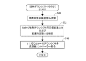
このため図1のハイブリッドコントローラ21は、HEV走行中に図3のモード切り替え制御プログラムを開始する。
また図3の制御プログラムは、電動モータ2による回生制動の許可条件が満足されるとき、例えば電動モータ2の温度が発電を行っても大丈夫な低温域であり、且つ、バッテリ12の温度が充電可能な低温域であり、且つ、バッテリ12が充電余力を残している蓄電状態であるときに実行するのは言うまでもない。
Therefore, the
In addition, the control program in FIG. 3 indicates that when the permit condition for regenerative braking by the
ステップS11においては、アクセル開度APOからアクセルペダル19が釈放されているコースティング走行か否かをチェックし、ステップS12においては、ブレーキスイッチ26がON(ブレーキペダル16が踏み込まれている制動状態)か否かをチェックする。
本実施例は、アクセルペダル19を釈放し、且つブレーキペダル16を踏み込んだときに回生制動を行うものを前提としており、従って、
ステップS11でアクセルペダル19が釈放状態でないと判定したり、ステップS12でブレーキスイッチ26がONでない(非制動状態)と判定する時は、制御をそのまま終了して図3の制御プログラムから抜ける。
In step S11, it is checked whether or not the coasting driving is performed with the
This embodiment is based on the assumption that when the
If it is determined in step S11 that the
ちなみに、アクセルペダル19が釈放されているコースティング走行中は、エンジン動力が不要であるからエンジン1への燃料供給を中断(フューエルカット)して、燃費の向上を図るのは通常通りである。
Incidentally, during coasting running when the
ステップS11でアクセルペダル19が釈放状態であると判定し、且つステップS12でブレーキスイッチ26がON(制動状態)と判定する時、回生制動条件が揃ったことで制御をステップS13に進め、現在のHEV走行のもと運転状態に応じた所定減速度が得られるよう回生制動(HEV回生)を行う。
本実施例はブレーキスイッチ26のON(制動状態)を、HEV回生からクラッチCLの解放により行うEV回生への移行要件とするため、ステップS12が、本発明におけるクラッチ解放許可判定手段に相当する。
When it is determined in step S11 that the
In this embodiment, since the
次のステップS14においては、ステップS12でのブレーキスイッチON(制動)判定が設定時間ΔTs以上継続したか否かを、つまりブレーキスイッチON時間ΔT(HEV回生時間)が設定時間ΔTs以上か否かをチェックし、回生制動の開始時から設定時間経過後であるか否かを判定する。 In the next step S14, it is determined whether or not the brake switch ON (braking) determination in step S12 has continued for a set time ΔTs or more, that is, whether or not the brake switch ON time ΔT (HEV regeneration time) is not less than the set time ΔTs. A check is made to determine whether or not a set time has elapsed since the start of regenerative braking.
ここで、上記したブレーキスイッチON時間ΔT(HEV回生時間)に係わる設定時間ΔTsについて説明する。
図4は、HEV回生開始時からクラッチCLの解放によるEV回生開始時までのクラッチ解放遅延時間ΔTごとに得られる回生エネルギー(燃費)と、エンジン再始動頻度(スタータモータ3の起動回数)との組み合わせを、回生エネルギー(燃費)の目標達成域およびスタータモータ3の耐久起動回数(スタータモータ保護成立域の限界起動回数)と共に例示するものである。
Here, the set time ΔTs related to the brake switch ON time ΔT (HEV regeneration time) will be described.
FIG. 4 shows the relationship between the regenerative energy (fuel consumption) obtained for each clutch release delay time ΔT from the start of HEV regeneration to the start of EV regeneration by releasing the clutch CL, and the engine restart frequency (
図4のデータは、実験などにより予め求めることができ、GOOD領域においては回生エネルギー(燃費)の目標を達成し得ると共に、スタータモータ3の起動回数が保護成立限界起動回数未満であってスタータモータ3の保護も成立させ得る。
しかしそれ以外のNG領域は、回生エネルギー(燃費)の目標を達成し得ないか、或いはスタータモータ3の起動回数が保護成立限界起動回数以上であってスタータモータ3の保護を成立させ得ないため、トレードオフの関係にあるエネルギー回生効率の向上要求およびスタータモータの保護要求を両立させることができない。
The data shown in FIG. 4 can be obtained in advance by experiments and the like. In the GOOD region, the target of regenerative energy (fuel consumption) can be achieved, and the
However, in other NG areas, the target of regenerative energy (fuel consumption) cannot be achieved, or the
この両立を実現するためには、HEV回生開始時からクラッチCLの解放によるEV回生開始時までのクラッチ解放遅延時間ΔTが図4のGOOD領域内における時間、つまりΔT1以上であって、ΔT2未満である必要がある。
そこで本実施例においては、上記したブレーキスイッチON時間ΔT(HEV回生時間)に係わる設定時間ΔTsとして、図4における時間ΔT1を用いる。
In order to achieve this compatibility, the clutch release delay time ΔT from the start of HEV regeneration to the start of EV regeneration due to the release of the clutch CL is longer than the time in the GOOD region of FIG. 4, that is, ΔT1, and less than ΔT2. There must be.
Therefore, in this embodiment, the time ΔT1 in FIG. 4 is used as the set time ΔTs related to the brake switch ON time ΔT (HEV regeneration time).
ステップS14でブレーキスイッチON時間ΔT(HEV回生時間)が設定時間ΔTs未満であると判定する間は、ステップS20を経て制御をステップS13に戻すことで現在のHEV走行のまま、運転状態に応じた所定減速度が得られるようHEV回生を継続する。
ステップS14でブレーキスイッチON時間ΔT(HEV回生時間)が設定時間ΔTs以上になったと判定する時、制御をステップS15に進めてクラッチCLの解放を許可する。
While it is determined in step S14 that the brake switch ON time ΔT (HEV regeneration time) is less than the set time ΔTs, the control is returned to step S13 through step S20, and the current HEV traveling is maintained according to the driving state. Continue HEV regeneration so that a predetermined deceleration is obtained.
When it is determined in step S14 that the brake switch ON time ΔT (HEV regeneration time) is equal to or longer than the set time ΔTs, the control proceeds to step S15 to permit the release of the clutch CL.
次のステップS16においては、前記したごとくフューエルカットされているエンジン1への燃料供給再開(フューエルリカバー)を禁止してフューエルカットを継続させる。
In the next step S16, resumption of fuel supply (fuel recovery) to the
ステップS17においては、締結状態のクラッチCLを介したエンジン1および無段変速機4の引き摺り減速度Gdを、CVTプーリ比(無段変速機4の変速比)i、エンジン回転数Neおよび車速VSPから演算する。
そしてステップS18で、HEV→EVモード切り替え条件の成立下にクラッチCLを解放し、これにより、ステップS16でのフューエルリカバー禁止(フューエルカット継続)と相まってエンジン1を停止させることでEV走行へ移行し、HEV回生からEV回生へと切り替える。
従ってステップS14およびステップS18は、本発明におけるモード切り替え手段に相当する。
In step S17, drag deceleration Gd of
Then, in step S18, the clutch CL is released under the condition that the HEV → EV mode switching condition is satisfied, and the
Therefore, step S14 and step S18 correspond to the mode switching means in the present invention.
ところで、当該EV回生への切り替え後もステップS13の回生制動を継続したのでは、ここでの回生制動が、締結状態のクラッチCLを介しエンジン1および無段変速機4を引き摺るHEV走行を前提とした回生制動であるため、エンジン1および無段変速機4の引き摺り減速度分だけ車両減速度が要求に対して不足する。
そのためステップS19において、ステップS17で求めたエンジン1および無段変速機4の引き摺り減速度分Gdを回生制動力に上乗せし、当該上乗せした回生制動力が得られるようなEV回生を行って、EV回生への切り替え後も、現在のEV走行のもと運転状態に応じた所定減速度が得られるようにする。
By the way, if the regenerative braking in step S13 is continued even after switching to the EV regenerative operation, the regenerative braking here is premised on HEV traveling in which the
Therefore, in step S19, the drag deceleration Gd of the
ところで図1のハイブリッド車両にあっては、HEV走行中にアクセルペダル19を釈放してコースティング走行へ移行し、且つブレーキペダル16の踏み込みにより制動を開始した場合、上記の通りエンジン1を停止すると共にクラッチCLを解放してHEV走行モードからEV走行モードに切り替わり、
当該EV走行中に制動操作をやめてアクセルペダル19を踏み込む再加速操作(発進を含む)が行われた場合、エンジン1を再始動すると共にクラッチCLを締結してEV走行モードからHEV走行モードに切り替わる。
By the way, in the hybrid vehicle of FIG. 1, when the
If a re-acceleration operation (including starting) is performed while stopping the braking operation and depressing the
そして上記の発進を含む再加速時は、大きな車輪駆動力(トルク)が必要であることから、無段変速機4が変速比iをできるだけロー側変速比にされている必要がある。
しかし、エンジン1を停止すると共にクラッチCLを解放させて行うHEV→EVモード切り替え時における無段変速機4の変速をハードウエアの成り行きに任せたのでは、
当該モード切り替え時にエンジン1を停止すると共にクラッチCLを解放させることから、エンジン駆動されるポンプO/Pからの作動油が得られないことによって、無段変速機1は変速不能となり、当該HEV→EVモード切り替え時の変速比のままにされる。
At the time of re-acceleration including the above-described start, since a large wheel driving force (torque) is required, it is necessary that the continuously
However, when the
Since the
この場合ハイブリッド車両は、HEV→EVモード切り替え後の発進を含む再加速時に無段変速機1がロー側変速比選択状態であることがほとんどなく、ハイ側変速比での再加速を余儀なくされて、駆動力不足により再加速(再発進)性能が悪くなるという問題を生ずる虞があった。
In this case, in the hybrid vehicle, the continuously
本実施例においては、かかるHEV→EVモード切り替え後における再加速(再発進)性能の悪さに関した問題をも解消するため、ステップS14からステップS13への戻りループ中にステップS20を介挿して追加し、このステップS20で無段変速機4を強制的にダウンシフトさせるようにする。
つまり、ステップS14でΔT<ΔTsと判定する間に、つまりステップS12でのブレーキスイッチON(制動)判定(HEV→EVモード切り替え要求判定)が設定時間ΔTs以上に亘って継続したか否かを判定している間に、ステップS20において無段変速機4を強制的にダウンシフトさせる。
なお、ステップS14でΔT<ΔTsと判定する間は未だクラッチCLが締結状態であって、エンジン駆動されるポンプO/Pからのオイルで無段変速機4を変速させることができるため、上記した無段変速機4の強制ダウンシフトは遂行可能である。
従ってステップS20は、本発明における強制ダウンシフト手段に相当する。
In this embodiment, in order to solve the problem of poor reacceleration (restart) performance after switching from HEV to EV mode, it is added via step S20 in the return loop from step S14 to step S13. In step S20, the continuously
That is, during the determination of ΔT <ΔTs in step S14, that is, whether or not the brake switch ON (braking) determination (HEV → EV mode switching request determination) in step S12 has continued for the set time ΔTs or more. During this time, the continuously
Note that the clutch CL is still engaged while determining ΔT <ΔTs in step S14, and the continuously
Therefore, step S20 corresponds to forced downshift means in the present invention.
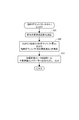
ステップS20における無段変速機4の強制ダウンシフトに際しては、種々の方法を用いることができ、例えば図5の制御プログラムに示すような方法がある。
図5のステップS21においては、ブレーキペダル16の踏み込み状態(ペダル踏力、ペダル踏み込み量、ブレーキ液圧)などから車両の要求減速度Gaを演算し、
ステップS22においては、この要求減速度Gaから制御1回当たりのダウンシフト量Δiおよび強制ダウンシフト用目標変速比idを検索などにより求める。
In the forced downshift of the continuously
In step S21 of FIG. 5, the required deceleration Ga of the vehicle is calculated from the depression state of the brake pedal 16 (pedal depression force, pedal depression amount, brake fluid pressure), etc.
In step S22, the amount of downshift Δi per control and the target gear ratio id for forced downshift are obtained from the required deceleration Ga by searching or the like.
なお制御1回当たりのダウンシフト量Δiは、要求減速度Gaが高いほど大きなダウンシフト量として、要求減速度Gaが高いほど強制ダウンシフトを高速で行わせるようなものとするが、基本的に強制ダウンシフトの変速速度が、予定の変速パターンに基づく通常のダウンシフトの変速速度よりも高速となるよう、制御1回当たりのダウンシフト量Δiを決定する。 The downshift amount Δi per control is such that the larger the required deceleration Ga, the larger the downshift amount, and the higher the required deceleration Ga, the faster the forced downshift is performed. The downshift amount Δi per control is determined so that the forced downshift speed is higher than the normal downshift speed based on the planned shift pattern.
また強制ダウンシフト用目標変速比idは、要求減速度Gaが高いほどロー側変速比として、要求減速度Gaごとに再加速時の要求駆動力を実現可能となるようなものとする。 Further, the target downshift target id ratio id is set such that the higher the required deceleration Ga, the lower the gear ratio, and the required driving force at the time of reacceleration can be realized for each required deceleration Ga.
次のステップS23においては、前回の変速比i(前回値)に制御1回当たりのダウンシフト量Δiを加算して今回の目標変速比iを求め、この目標変速比iを変速機コントローラ24に指令することで、無段変速機4を制御1回当たりのダウンシフト量Δiに応じた速度でダウンシフトさせる。
但し、この強制ダウンシフトによる限界変速比は上記の強制ダウンシフト用目標変速比idとし、要求減速度Gaごとに再加速時の要求駆動力が実現可能となるようにする。
In the next step S23, the current target speed ratio i is obtained by adding the downshift amount Δi per control to the previous speed ratio i (previous value), and this target speed ratio i is transmitted to the
However, the limit gear ratio by this forced downshift is the above-mentioned forced downshift target gear ratio id, so that the required driving force at the time of reacceleration can be realized for each required deceleration Ga.
図3,5のモード切り替え制御を、図6のタイムチャートに基づき以下に詳述する。
クラッチCLを締結したHEV走行中、図6の瞬時t0にアクセルペダル19を釈放してアクセル開度APO=0のコースティング走行に移行すると(ステップS11)、エンジン1への燃料供給を中断(フューエルカット)して燃料噴射量を0にする(図6に示していない)。
The mode switching control in FIGS. 3 and 5 will be described in detail below based on the time chart in FIG.
During HEV driving with the clutch CL engaged, when the
瞬時t1に、ブレーキスイッチ26=ONにより示すごとくブレーキペダル16を踏み込んで制動を行うと(ステップS12)、本実施例における回生制動条件が揃ったことでHEV回生が開始される(ステップS13)。
このHEV回生により電動モータ2は、HEV走行中の運転状態に応じた所定減速度が得られるよう回生制動を行うことで、図6の瞬時t1以降における車速VSPの低下(図6では3種類の減速度を例示した)から明らかなように車両を減速させることができ、減速エネルギー分を発電してバッテリに蓄電する。
When braking is performed by depressing the
This HEV regeneration causes the
瞬時t1からのブレーキスイッチON時間ΔT(HEV回生時間)が所定時間ΔTsに達する(ステップS14)瞬時t2までの間は、上記のHEV回生を継続する。
瞬時t1からのブレーキスイッチON時間ΔT(HEV回生時間)が所定時間ΔTsに達する(ステップS14)瞬時t2に、いままで締結状態だったクラッチCLを解放してエンジン1を、ステップS16でのフューエルリカバー禁止により継続されるフューエルカット(燃料噴射量=0)で停止させる(ステップS16およびステップS18)。
これにより瞬時t2にHEV走行からEV走行へとモードが切り替わり、瞬時t2からEV回生が行われることとなる。
The above-mentioned HEV regeneration is continued until the instant t2 when the brake switch ON time ΔT (HEV regeneration time) from the instant t1 reaches the predetermined time ΔTs (step S14).
The brake switch ON time ΔT (HEV regeneration time) from the instant t1 reaches the predetermined time ΔTs (step S14) At the instant t2, the clutch CL that has been engaged is released and the
As a result, the mode is switched from HEV traveling to EV traveling at the instant t2, and EV regeneration is performed from the instant t2.
一方で本実施例においては、瞬時t1からのブレーキスイッチON時間ΔT(HEV回生時間)が所定時間ΔTsに達する(ステップS14)瞬時t2までの間に、ステップS20において図5の制御プログラムを実行することにより、無段変速機4を図6における変速比iの二点鎖線、一点鎖線、および実線で示す変化から明らかなように強制的にダウンシフトさせる。
変速比iの二点鎖線で示す変化は要求減速度Gaが小さい時のもので、一点鎖線で示す変化は要求減速度Gaがそれよりも大きい時のもので、実線で示す変化は要求減速度Gaが更に大きい時のものである。
On the other hand, in the present embodiment, the brake switch ON time ΔT (HEV regeneration time) from the instant t1 reaches the predetermined time ΔTs (step S14), and the control program of FIG. 5 is executed in step S20 until the instant t2. As a result, the continuously
The change indicated by the two-dot chain line of the gear ratio i is when the required deceleration Ga is small, the change indicated by the one-dot chain line is when the required deceleration Ga is larger, and the change indicated by the solid line is the required deceleration. This is when Ga is even larger.
なお図6には比較のため、車両減速度がそれぞれ上記3種類の要求減速度Gaと同じである場合における通常変速時の変速比変化を3本の破線で併記した。
これら3本の破線との比較から明らかなように、要求減速度Gaが小さい場合における二点鎖線で示す変速比iは、HEV→EVモード切り替え時t2において通常変速時よりもΔi1だけロー側の変速比となり、それよりも要求減速度Gaが大きい場合における一点鎖線で示す変速比iは、HEV→EVモード切り替え時t2において通常変速時よりもΔi2だけロー側の変速比となり、それよりも更に要求減速度Gaが大きい場合における実線で示す変速比iは、HEV→EVモード切り替え時t2において通常変速時よりもΔi3だけロー側の変速比となる。
For comparison, FIG. 6 also shows the change in the gear ratio at the time of the normal shift when the vehicle deceleration is the same as the above-described three types of required deceleration Ga, along with three broken lines.
As is clear from the comparison with these three broken lines, the gear ratio i indicated by the two-dot chain line when the required deceleration Ga is small is lower by Δi1 than the normal gear shift at t2 when the HEV → EV mode is switched. The gear ratio i indicated by the alternate long and short dash line when the required deceleration Ga is larger than that is the gear ratio on the low side by Δi2 from the normal gear shift at t2 when switching from HEV to EV mode, and even more The speed change ratio i indicated by the solid line when the required deceleration Ga is large is a speed change ratio on the low side by Δi3 from the time of the normal speed change at t2 when the HEV → EV mode is switched.
よって、いずれの要求減速度Gaのもとでも、HEV→EVモード切り替え時t2に変速比iが通常変速時よりもロー側の変速比にされることとなり、瞬時t2以降における発進を含む再加速をロー側変速比による大きな駆動力で行うことができ、駆動力不足による再加速(再発進)性能の悪化を生ずることがない。 Therefore, under any required deceleration Ga, the gear ratio i is set to a lower gear ratio than the normal gear ratio at t2 when the HEV → EV mode is switched, and re-acceleration including start after the instant t2 Can be performed with a large driving force due to the low gear ratio, and re-acceleration (restart) performance does not deteriorate due to insufficient driving force.
<第1実施例の効果>
上記した第1実施例の回生制動制御によれば、ブレーキスイッチON時間ΔT(HEV→EVモードへの切り替えに際して必要なクラッチCLの解放を許可する制動状態の継続時間)が所定時間ΔTs以上になった時(ステップS14)、クラッチCLの解放(HEV回生から、エンジン1の停止を伴うEV回生への切り替え)を許可するため(ステップS15)、
当該クラッチCLの解放(HEV回生から、エンジン1の停止を伴うEV回生への切り替え)が、HEV回生の開始時(ブレーキスイッチ26のON時)より後であるも、スタータモータの保護に必要な時間内のできるだけ早い所定タイミングで許可されることとなる。
<Effects of the first embodiment>
According to the regenerative braking control of the first embodiment described above, the brake switch ON time ΔT (the duration of the braking state permitting the release of the clutch CL necessary for switching from HEV to EV mode) is equal to or longer than the predetermined time ΔTs. (Step S14) to permit the release of the clutch CL (switching from HEV regeneration to EV regeneration with the
Even if the clutch CL is released (from HEV regeneration to EV regeneration with
このため、HEV→EVモードへの切り替えに際して必要なクラッチCLの解放を許可する制動の開始のみをもってクラッチCLの解放(HEV回生から、エンジン1の停止を伴うEV回生への切り替え)が行われることがなく、HEV→EVモード切り替え要求(ブレーキ操作)が頻繁に発生したり、消失するような運転中であっても、エンジン再始動が頻発するのを防止することができる。
よって当該運転によっても、スタータモータ3の起動回数が早期に耐久起動回数に達することがなく、スタータモータ3の耐久性に関した問題を回避することができ、スタータモータ3の保護を図り得る。
Therefore, the clutch CL is released only from the start of braking that permits the release of the clutch CL necessary for switching from the HEV to the EV mode (switching from HEV regeneration to EV regeneration with the
Therefore, even with this operation, the
また、HEV回生の開始時(ブレーキスイッチ26のON時)よりも後にクラッチCLの解放(HEV回生から、エンジン1の停止を伴うEV回生への切り替え)を許可するといっても、スタータモータ3の保護に必要なできるだけ早い所定タイミングに当該許可を指令するため、
上記クラッチCLの解放(HEV回生→EV回生切り替え)タイミングはHEV回生の開始時から、スタータモータ3の耐久性に関する問題解決のために必要な最小限の時間だけ遅いのみであり、これによるエネルギー回生効率の悪化は僅かで無視できる。
従って本実施例によるハイブリッド車両の回生制動制御装置は、スタータモータ3の保護に関した要求と、エネルギー回生効率に関した要求とを、高次元でバランスさせつつ両立させることができ、いずれかが大きく犠牲になるという問題を生ずることがない。
Even if the release of the clutch CL is permitted after the start of HEV regeneration (when the
The clutch CL release timing (HEV regeneration → EV regeneration switching) is only delayed by the minimum time necessary to solve the problem related to the durability of the
Therefore, the regenerative braking control device for a hybrid vehicle according to the present embodiment can satisfy both the requirements related to protection of the
更に本実施例においては、上記した作用効果を得るために定めた設定時間ΔTs中、未だクラッチCLが締結されているHEVモードであって、エンジン駆動されるオイルポンプO/Pからの作動油で無段変速機4を変速させることができるとの観点から、
この設定時間ΔTsを有効利用して当該時間中に、無段変速機4を強制的にダウンシフトさせるようにしたため(ステップS20)、
HEVモードからEVモードへのモード切り替え後の発進を含む再加速時に無段変速機4が通常変速によるよりもロー側変速比にされていることとなり、当該発進を含む再加速がロー側変速比で開始されることとなる。
このため、発進を含む再加速がハイ側変速比で開始されることがなく、駆動力不足により再加速(再発進)性能が悪くなるという問題を解消することができる。
Further, in the present embodiment, the HEV mode in which the clutch CL is still engaged during the set time ΔTs determined in order to obtain the above-described operation and effect, with hydraulic oil from the oil pump O / P driven by the engine. From the viewpoint that the continuously
Since the set time ΔTs is effectively used and the continuously
At the time of re-acceleration including the start after switching from the HEV mode to the EV mode, the continuously
For this reason, the reacceleration including the start is not started at the high gear ratio, and the problem that the reacceleration (restart) performance deteriorates due to insufficient driving force can be solved.
また上記の強制ダウンシフトの変速速度を要求減速度Gaが高いほど速くしたため、車両減速度の如何に関わらず上記の効果を達成し得る。
さらに強制ダウンシフトの変速速度が通常ダウンシフトよりも高速になるよう構成したため、上記の効果を確実なものにし得る。
そして強制ダウンシフト時の限界変速比を、要求減速度Gaが高いほど大きく定めたダウンシフト用目標変速比idとしたため、要求減速度Gaごとに再加速時の要求駆動力を実現することができ、要求減速度Gaの如何に関わらず上記の効果を確実なものにし得る。
Further, since the shift speed of the forced downshift is increased as the required deceleration Ga is higher, the above-described effect can be achieved regardless of the vehicle deceleration.
Furthermore, since the shift speed of the forced downshift is configured to be higher than that of the normal downshift, the above effect can be ensured.
And, because the limit gear ratio at the time of forced downshift is set as the target gear ratio id for downshift that is set larger as the required deceleration Ga is higher, the required driving force at the time of reacceleration can be realized for each required deceleration Ga. The above effect can be ensured regardless of the required deceleration Ga.
<第2実施例のモード切り替え制御>
図7は、本発明の第2実施例になるモード切り替え制御の強制ダウンシフト要領を示す、図5と同様な制御プログラムである。
本実施例も、第1実施例と同様、図1または図2(a)に示す駆動系を持ったハイブリッド車両のモード切り替え制御に係わるが、駆動系が図1のようなものである場合につき説明を展開する。
<Mode switching control of the second embodiment>
FIG. 7 is a control program similar to FIG. 5, showing the forced downshift procedure of the mode switching control according to the second embodiment of the present invention.
Like the first embodiment, this embodiment also relates to the mode switching control of the hybrid vehicle having the drive system shown in FIG. 1 or FIG. 2 (a), but the case where the drive system is as shown in FIG. Expand the description.
本実施例においても、モード切り替え制御は図3に示すと同様なものとし、本実施例は、同図におけるステップS20で行うべき無段変速機4の強制ダウンシフトを、図5に代え図7の制御プログラムに沿って、以下のごとくに遂行するものとする。
Also in this embodiment, the mode switching control is the same as shown in FIG. 3, and this embodiment replaces the forced downshift of the continuously
図7のステップS31においては、ブレーキペダル16の踏み込み状態(ペダル踏力、ペダル踏み込み量、ブレーキ液圧)などから車両の要求減速度Gaを演算し、
ステップS22においては、この要求減速度Gaから強制ダウンシフト用目標変速比idおよび変速時定数τを検索などにより求める。
In step S31 of FIG. 7, the required deceleration Ga of the vehicle is calculated from the depression state of the brake pedal 16 (pedal depression force, pedal depression amount, brake fluid pressure), etc.
In step S22, the forced downshift target gear ratio id and the shift time constant τ are obtained from the required deceleration Ga by searching or the like.
強制ダウンシフト用目標変速比idは、要求減速度Gaが高いほどロー側変速比として、要求減速度Gaごとに再加速時の要求駆動力を実現可能となるようなものとする。
また変速時定数τは、要求減速度Gaが高いほど小さくして、強制ダウンシフトの変速速度が速くなるようにするが、基本的に強制ダウンシフトの変速速度が、予定の変速パターンに基づく通常のダウンシフトの変速速度よりも高速となるよう、変速時定数τを決定する。
The target downshift target speed ratio id is set such that the higher the required deceleration Ga, the lower the gear ratio, so that the required driving force during reacceleration can be realized for each required deceleration Ga.
The shift time constant τ is decreased as the required deceleration Ga is increased so that the forced downshift speed is increased. Basically, the forced downshift speed is normally set based on the planned shift pattern. The shift time constant τ is determined so as to be higher than the shift speed of the downshift.
次のステップS33においては、現在の変速比から強制ダウンシフト用目標変速比idへ変速時定数τに応じた速度で変速させるための目標変速比iを求め、この目標変速比iを変速機コントローラ24に指令することで、無段変速機4を変速時定数τに応じた速度で強制ダウンシフト用目標変速比idへと強制的にダウンシフトさせる。
なお、この強制ダウンシフトによる限界変速比は上記の強制ダウンシフト用目標変速比idであり、要求減速度Gaごとに再加速時の要求駆動力が実現可能である。
In the next step S33, a target speed ratio i for shifting from the current speed ratio to the target downshift target speed ratio id at a speed corresponding to the speed change time constant τ is obtained, and this target speed ratio i is obtained from the transmission controller. By commanding to 24, the continuously
The limit gear ratio by this forced downshift is the target gear ratio id for forced downshift described above, and the required driving force at the time of reacceleration can be realized for each required deceleration Ga.
<第2実施例の効果>
本実施例による図3,7のモード切り替え制御も、図6のタイムチャートにつき前述したと同様に行われ、第1実施例と同様な作用効果を奏し得て、エネルギー回生効率の向上要求およびスタータモータの保護要求を両立させ得ると共に、この作用効果のために定めた設定時間ΔTs中における無段変速機4の強制ダウンシフトにより、発進を含む再加速がロー側変速比で開始され、駆動力不足により再加速(再発進)性能が悪くなるという問題を解消することができる。
<Effect of the second embodiment>
The mode switching control of FIGS. 3 and 7 according to the present embodiment is also performed in the same manner as described above with reference to the time chart of FIG. 6, and can achieve the same operational effects as those of the first embodiment. The motor's protection requirements can be made compatible, and the re-acceleration including starting is started at the low gear ratio by the forced downshift of the continuously
また上記の強制ダウンシフトの変速速度に係わる変速時定数τを要求減速度Gaが高いほど小さくして、強制ダウンシフト速度を要求減速度Gaが高いほど速くしたため、車両減速度の如何に関わらず上記の効果を達成し得る。
さらに強制ダウンシフトの変速速度が通常ダウンシフトよりも高速になるよう変速時定数τを決定したため、上記の効果を確実なものにし得る。
そして強制ダウンシフト時の限界変速比が、要求減速度Gaが高いほど大きく定めたダウンシフト用目標変速比idであることから、要求減速度Gaごとに再加速時の要求駆動力を実現することができ、要求減速度Gaの如何に関わらず上記の効果を確実なものにし得る。
In addition, the shift time constant τ related to the shift speed of the forced downshift is decreased as the required deceleration Ga is increased, and the forced downshift speed is increased as the required deceleration Ga is increased, so that regardless of the vehicle deceleration. The above effects can be achieved.
Furthermore, since the shift time constant τ is determined so that the shift speed of the forced downshift is higher than that of the normal downshift, the above effect can be ensured.
And because the limit gear ratio at the time of forced downshift is the target gear ratio id for the downshift that is set larger as the required deceleration Ga is higher, the required driving force at the time of reacceleration is realized for each required deceleration Ga The above effect can be ensured regardless of the required deceleration Ga.
<第3実施例のモード切り替え制御>
図8は、本発明の第3実施例になるモード切り替え制御の強制ダウンシフト要領を示す、図5と同様な制御プログラムである。
本実施例も、第1実施例と同様、図1または図2(a)に示す駆動系を持ったハイブリッド車両のモード切り替え制御に係わるが、駆動系が図1のようなものである場合につき説明を展開する。
<Mode switching control of the third embodiment>
FIG. 8 is a control program similar to FIG. 5 showing the forced downshift procedure of the mode switching control according to the third embodiment of the present invention.
Like the first embodiment, this embodiment also relates to the mode switching control of the hybrid vehicle having the drive system shown in FIG. 1 or FIG. 2 (a), but the case where the drive system is as shown in FIG. Expand the description.
本実施例においても、モード切り替え制御は図3に示すと同様なものとし、本実施例は、同図におけるステップS20で行うべき無段変速機4の強制ダウンシフトを、図5に代え図8の制御プログラムに沿って、以下のごとくに遂行するものとする。
Also in this embodiment, the mode switching control is the same as that shown in FIG. 3, and this embodiment replaces the forced downshift of the continuously
図8のステップS41においては、ブレーキペダル16の踏み込み状態(ペダル踏力、ペダル踏み込み量、ブレーキ液圧)などから車両の要求減速度Gaを演算し、
ステップS42においては、この要求減速度Gaから強制ダウンシフト用目標変速比idおよび変速制御圧の変化率ΔPを検索などにより求める。
In step S41 of FIG. 8, the required deceleration Ga of the vehicle is calculated from the depression state of the brake pedal 16 (pedal depression force, pedal depression amount, brake fluid pressure), etc.
In step S42, the forced downshift target gear ratio id and the change rate ΔP of the shift control pressure are obtained from the required deceleration Ga by searching or the like.
強制ダウンシフト用目標変速比idは、要求減速度Gaが高いほどロー側変速比として、要求減速度Gaごとに再加速時の要求駆動力を実現可能となるようなものとする。
また変速制御圧の変化率ΔPは、要求減速度Gaが高いほど大きくして、強制ダウンシフトの変速速度が速くなるようにするが、基本的に強制ダウンシフトの変速速度が、予定の変速パターンに基づく通常のダウンシフトの変速速度よりも高速となるよう、変速制御圧の変化率ΔPを決定する。
The target downshift target speed ratio id is set such that the higher the required deceleration Ga, the lower the gear ratio, so that the required driving force during reacceleration can be realized for each required deceleration Ga.
In addition, the change rate ΔP of the shift control pressure is increased as the required deceleration Ga is increased, so that the shift speed of the forced downshift is increased. Basically, the shift speed of the forced downshift is the expected shift pattern. The change rate ΔP of the shift control pressure is determined so as to be higher than the normal shift speed of the downshift based on the above.
次のステップS43においては、変速制御圧を現在の値から上記変化率ΔPで強制ダウンシフト用目標変速比idに対応した変速制御圧に向かわせるよう変速機コントローラ24に指令することで、無段変速機4を変速制御圧変化率ΔPに応じた速度で強制ダウンシフト用目標変速比idへと強制的にダウンシフトさせる。
なお、この強制ダウンシフトによる限界変速比は上記の強制ダウンシフト用目標変速比idであり、要求減速度Gaごとに再加速時の要求駆動力が実現可能である。
In the next step S43, the transmission controller pressure is commanded to the
The limit gear ratio by this forced downshift is the target gear ratio id for forced downshift described above, and the required driving force at the time of reacceleration can be realized for each required deceleration Ga.
<第3実施例の効果>
本実施例による図3,8のモード切り替え制御も、図6のタイムチャートにつき前述したと同様に行われ、第1実施例と同様な作用効果を奏し得て、エネルギー回生効率の向上要求およびスタータモータの保護要求を両立させ得ると共に、この作用効果のために定めた設定時間ΔTs中における無段変速機4の強制ダウンシフトにより、発進を含む再加速がロー側変速比で開始され、駆動力不足により再加速(再発進)性能が悪くなるという問題を解消することができる。
<Effect of the third embodiment>
The mode switching control of FIGS. 3 and 8 according to the present embodiment is also performed in the same manner as described above with reference to the time chart of FIG. 6, and the same operational effects as the first embodiment can be obtained. The motor's protection requirements can be made compatible, and the re-acceleration including starting is started at the low gear ratio by the forced downshift of the continuously
また上記の強制ダウンシフトの変速速度に係わる変速制御圧変化率ΔPを要求減速度Gaが高いほど大きくして、強制ダウンシフト速度を要求減速度Gaが高いほど速くしたため、車両減速度の如何に関わらず上記の効果を達成し得る。
さらに強制ダウンシフトの変速速度が通常ダウンシフトよりも高速になるよう変速制御圧変化率ΔPを決定したため、上記の効果を確実なものにし得る。
そして強制ダウンシフト時の限界変速比が、要求減速度Gaが高いほど大きく定めたダウンシフト用目標変速比idであることから、要求減速度Gaごとに再加速時の要求駆動力を実現することができ、要求減速度Gaの如何に関わらず上記の効果を確実なものにし得る。
Also, since the shift control pressure change rate ΔP related to the shift speed of the forced downshift is increased as the required deceleration Ga is higher, the forced downshift speed is increased as the required deceleration Ga is higher. Regardless, the above effects can be achieved.
Furthermore, since the shift control pressure change rate ΔP is determined so that the shift speed of the forced downshift is higher than that of the normal downshift, the above effect can be ensured.
And because the limit gear ratio at the time of forced downshift is the target gear ratio id for the downshift that is set larger as the required deceleration Ga is higher, the required driving force at the time of reacceleration is realized for each required deceleration Ga The above effect can be ensured regardless of the required deceleration Ga.
1 エンジン(動力源)
2 電動モータ(動力源)
3 スタータモータ
4 Vベルト式無段変速機
5 駆動車輪
6 プライマリプーリ
7 セカンダリプーリ
8 Vベルト
CVT 無段変速機構
T/C トルクコンバータ
CL クラッチ
9,11 ファイナルギヤ組
12 バッテリ
13 インバータ
14 ブレーキディスク
15 キャリパ
16 ブレーキペダル
17 負圧式ブレーキブースタ
18 マスターシリンダ
19 アクセルペダル
21 ハイブリッドコントローラ
22 エンジンコントローラ
23 モータコントローラ
24 変速機コントローラ
25 バッテリコントローラ
26 ブレーキスイッチ
27 アクセル開度センサ
O/P オイルポンプ
31 副変速機
H/C ハイクラッチ
R/B リバースブレーキ
L/B ローブレーキ
32 車速センサ
33 車両加速度センサ
35 ライン圧ソレノイド
36 ロックアップソレノイド
37 プライマリプーリ圧ソレノイド
38 ローブレーキ圧ソレノイド
39 ハイクラッチ圧&リバースブレーキ圧ソレノイド
41 スイッチバルブ
1 Engine (power source)
2 Electric motor (power source)
3 Starter motor
4 V belt type continuously variable transmission
5 Drive wheels
6 Primary pulley
7 Secondary pulley
8 V belt
CVT continuously variable transmission mechanism
T / C torque converter
CL clutch
9,11 Final gear set
12 battery
13 Inverter
14 Brake disc
15 Caliper
16 Brake pedal
17 Negative pressure brake booster
18 Master cylinder
19 Accelerator pedal
21 Hybrid controller
22 Engine controller
23 Motor controller
24 Transmission controller
25 Battery controller
26 Brake switch
27 Accelerator position sensor
O / P oil pump
31 Sub-transmission
H / C high clutch
R / B reverse brake
L / B Low brake
32 Vehicle speed sensor
33 Vehicle acceleration sensor
35 line pressure solenoid
36 Lock-up solenoid
37 Primary pulley pressure solenoid
38 Low brake pressure solenoid
39 High clutch pressure & reverse brake pressure solenoid
41 Switch valve
Claims (11)
前記ハイブリッド走行モードで、前記電気走行モードへの切り替えに際して必要な前記クラッチの解放を許可すべきクラッチ解放許可運転になったか否かを判定するクラッチ解放許可判定手段と、
該手段で前記クラッチ解放許可運転になったと判定された後、該クラッチの解放を許可すべきでないクラッチ解放不許可運転に戻らなかったのを確認した時、前記クラッチの解放を実行して前記ハイブリッド走行モードから電気走行モードへの切り替えを行うモード切り替え手段と、
前記クラッチ解放不許可運転へ戻らなかったのを確認するための時間中に前記無段変速機を強制的にロー側変速比に向けてダウンシフトさせる強制ダウンシフト手段を設けたことを特徴とするハイブリッド車両のモード切り替え制御装置。 In addition to the engine as a power source, an electric motor is provided, and the engine is operatively coupled to the wheels through a continuously variable transmission and a clutch that are controlled by a fluid from a pump driven by the engine as a medium. In addition to releasing the clutch and stopping the engine, it is possible to select an electric travel mode in which the vehicle travels only by the electric motor, and by starting the engine and engaging the clutch, the electric motor and In a hybrid vehicle mode switching control device capable of selecting a hybrid driving mode driven by an engine,
Clutch release permission determination means for determining whether or not a clutch release permission operation that should allow the release of the clutch necessary for switching to the electric travel mode in the hybrid travel mode;
When it is determined by the means that the clutch release permission operation has been performed and when it is confirmed that the clutch release permission operation that should not permit the clutch release is not returned, the clutch is released to execute the hybrid release. Mode switching means for switching from the traveling mode to the electric traveling mode;
Forcibly downshifting means for forcibly downshifting the continuously variable transmission toward the low side gear ratio during a time for confirming that the operation has not been returned to the clutch disapproval disapproval operation is provided. Hybrid vehicle mode switching control device.
前記強制ダウンシフト手段は、前記設定時間中に前記無段変速機の変速パターンに基づく通常ダウンシフトが行われる走行条件である場合、該通常ダウンシフトの変速速度よりも高速で前記強制ダウンシフトを行わせるものであることを特徴とするハイブリッド車両のモード切り替え制御装置。 In the hybrid vehicle mode switching control device according to claim 1,
The forced downshift means performs the forced downshift at a speed higher than a shift speed of the normal downshift when a normal downshift is performed based on a shift pattern of the continuously variable transmission during the set time. A mode switching control device for a hybrid vehicle, characterized in that it is performed.
前記強制ダウンシフト手段は、所定時間ごとに変速比を所定量ずつ増大させて前記強制ダウンシフトを行うものであることを特徴とするハイブリッド車両のモード切り替え制御装置。 In the hybrid vehicle mode switching control device according to claim 1 or 2,
The hybrid vehicle mode switching control device, wherein the forced downshift means performs the forced downshift by increasing a gear ratio by a predetermined amount every predetermined time.
前記強制ダウンシフト手段は、前記所定時間ごとの変速比の所定増大量を車両の要求減速度が高いほど大きくして、車両要求減速度が高いほど前記強制ダウンシフトの変速速度を速くするものであることを特徴とするハイブリッド車両のモード切り替え制御装置。 In the hybrid vehicle mode switching control device according to claim 3,
The forced downshift means increases a predetermined increase amount of the gear ratio every predetermined time as the required deceleration of the vehicle is higher, and increases a shift speed of the forced downshift as the required vehicle deceleration is higher. A mode switching control device for a hybrid vehicle, characterized in that:
前記強制ダウンシフト手段は、強制ダウンシフト用の目標変速比を定め、前記強制ダウンシフトの限界変速比を該強制ダウンシフト用目標変速比とするものであることを特徴とするハイブリッド車両のモード切り替え制御装置。 In the hybrid vehicle mode switching control device according to claim 3 or 4,
The forced downshift means determines a target speed ratio for forced downshift, and uses the limit speed ratio of the forced downshift as the target speed ratio for forced downshift. Control device.
前記強制ダウンシフト手段は、強制ダウンシフト用の目標変速比を定め、該強制ダウンシフト用目標変速比へ所定の時定数で変速させて前記強制ダウンシフトを行うものであることを特徴とするハイブリッド車両のモード切り替え制御装置。 In the hybrid vehicle mode switching control device according to claim 1 or 2,
The hybrid downshift means is configured to perform a forced downshift by determining a target gear ratio for a forced downshift and shifting to the target gear ratio for the forced downshift with a predetermined time constant. Vehicle mode switching control device.
前記強制ダウンシフト手段は、前記所定の変速時定数を車両の要求減速度が高いほど小さくして、車両要求減速度が高いほど前記強制ダウンシフトの変速速度を速くするものであることを特徴とするハイブリッド車両のモード切り替え制御装置。 In the hybrid vehicle mode switching control device according to claim 6,
The forced downshift means decreases the predetermined shift time constant as the vehicle required deceleration increases, and increases the forced downshift speed as the vehicle required deceleration increases. A mode switching control device for a hybrid vehicle.
前記強制ダウンシフト手段は、強制ダウンシフト用の目標変速比を定め、前記無段変速機の変速制御圧を所定の変化率で該強制ダウンシフト用目標変速比対応の圧力に変化させるものであることを特徴とするハイブリッド車両のモード切り替え制御装置。 In the hybrid vehicle mode switching control device according to claim 1 or 2,
The forced downshift means determines a target gear ratio for forced downshift, and changes the transmission control pressure of the continuously variable transmission to a pressure corresponding to the target gear ratio for forced downshift at a predetermined change rate. A mode switching control device for a hybrid vehicle characterized by the above.
前記強制ダウンシフト手段は、変速制御圧に係わる前記所定の変化率を車両の要求減速度が高いほど大きくして、車両要求減速度が高いほど前記変速制御圧を高速で強制ダウンシフト用目標変速比対応の圧力に向かわせるものであることを特徴とするハイブリッド車両のモード切り替え制御装置。 In the mode switching control device of the hybrid vehicle according to claim 8,
The forced downshift means increases the predetermined change rate related to the shift control pressure as the required deceleration of the vehicle increases, and increases the shift control pressure at a higher speed as the required deceleration of the vehicle increases. A mode switching control device for a hybrid vehicle characterized by being directed to a pressure corresponding to a ratio.
前記強制ダウンシフト手段は、前記強制ダウンシフト用目標変速比を車両の要求減速度が高いほどロー側変速比として、該車両要求減速度ごとに再加速時の要求駆動力を実現可能にしたものであることを特徴とするハイブリッド車両のモード切り替え制御装置。 In the hybrid vehicle mode switching control device according to any one of claims 5 to 9,
The forced downshift means is configured such that the target speed ratio for forced downshift is set to the lower side gear ratio as the required deceleration of the vehicle is higher, and the required driving force at the time of reacceleration can be realized for each required deceleration of the vehicle. A hybrid vehicle mode switching control device.
前記クラッチ解放不許可運転へ戻らなかったのを確認するための時間は、前記エンジンのスタータモータ起動回数が該スタータモータの耐久起動回数未満となるような時間であることを特徴とするハイブリッド車両のモード切り替え制御装置。 In the hybrid vehicle mode switching control device according to any one of claims 1 to 10,
The time period for confirming that the operation has not returned to the clutch release disapproval operation is such a time that the starter motor activation frequency of the engine is less than the durable activation frequency of the starter motor. Mode switching control device.
Priority Applications (1)
| Application Number | Priority Date | Filing Date | Title |
|---|---|---|---|
| JP2012268994A JP2014113902A (en) | 2012-12-10 | 2012-12-10 | Mode switching control system of hybrid vehicle |
Applications Claiming Priority (1)
| Application Number | Priority Date | Filing Date | Title |
|---|---|---|---|
| JP2012268994A JP2014113902A (en) | 2012-12-10 | 2012-12-10 | Mode switching control system of hybrid vehicle |
Publications (1)
| Publication Number | Publication Date |
|---|---|
| JP2014113902A true JP2014113902A (en) | 2014-06-26 |
Family
ID=51170400
Family Applications (1)
| Application Number | Title | Priority Date | Filing Date |
|---|---|---|---|
| JP2012268994A Pending JP2014113902A (en) | 2012-12-10 | 2012-12-10 | Mode switching control system of hybrid vehicle |
Country Status (1)
| Country | Link |
|---|---|
| JP (1) | JP2014113902A (en) |
Cited By (4)
| Publication number | Priority date | Publication date | Assignee | Title |
|---|---|---|---|---|
| KR101588760B1 (en) * | 2014-10-17 | 2016-01-26 | 현대자동차 주식회사 | Control apparatus and method of power transmission of hybrid elecric vehicle |
| EP3109116A1 (en) * | 2015-06-16 | 2016-12-28 | Toyota Jidosha Kabushiki Kaisha | Control system of vehicle |
| KR101704251B1 (en) * | 2015-08-27 | 2017-02-07 | 현대자동차주식회사 | Transmission method during engine stop control for hev vehicle and transmission apparatus therefor |
| CN106696718A (en) * | 2015-11-16 | 2017-05-24 | 福特环球技术公司 | Methods and system for mitigating undesirable conditions during regenerative braking |
-
2012
- 2012-12-10 JP JP2012268994A patent/JP2014113902A/en active Pending
Cited By (7)
| Publication number | Priority date | Publication date | Assignee | Title |
|---|---|---|---|---|
| KR101588760B1 (en) * | 2014-10-17 | 2016-01-26 | 현대자동차 주식회사 | Control apparatus and method of power transmission of hybrid elecric vehicle |
| US9493154B2 (en) | 2014-10-17 | 2016-11-15 | Hyundai Motor Company | Control apparatus and method of power transmission system for hybrid elecric vehicle |
| EP3109116A1 (en) * | 2015-06-16 | 2016-12-28 | Toyota Jidosha Kabushiki Kaisha | Control system of vehicle |
| RU2646780C2 (en) * | 2015-06-16 | 2018-03-07 | Тойота Дзидося Кабусики Кайся | Control system of vehicle |
| KR101704251B1 (en) * | 2015-08-27 | 2017-02-07 | 현대자동차주식회사 | Transmission method during engine stop control for hev vehicle and transmission apparatus therefor |
| CN106696718A (en) * | 2015-11-16 | 2017-05-24 | 福特环球技术公司 | Methods and system for mitigating undesirable conditions during regenerative braking |
| CN106696718B (en) * | 2015-11-16 | 2021-10-15 | 福特环球技术公司 | Method and system for mitigating adverse conditions during regenerative braking |
Similar Documents
| Publication | Publication Date | Title |
|---|---|---|
| US9963141B2 (en) | Hybrid vehicle control device with transmission control for a level difference of a road surface | |
| JP5936703B2 (en) | Hybrid vehicle mode switching control device | |
| JP5992537B2 (en) | Hybrid vehicle mode switching control device | |
| JP5835500B2 (en) | Control device for hybrid vehicle | |
| US9758158B2 (en) | Hybrid vehicle control device | |
| WO2012105601A1 (en) | Kick-down control device for electric vehicle | |
| JP2007261498A (en) | Transmission status switching controller for hybrid car | |
| JP6052775B2 (en) | Control device for hybrid vehicle | |
| WO2013146175A1 (en) | Shift controller for electric drive deceleration in hybrid vehicle | |
| JP6569095B2 (en) | Control device for hybrid vehicle | |
| JP6340605B2 (en) | Control device for hybrid vehicle | |
| WO2014065302A1 (en) | Mode switching controller for hybrid vehicle | |
| JP2014113902A (en) | Mode switching control system of hybrid vehicle | |
| JP6330190B2 (en) | Control device for hybrid vehicle | |
| JP6113478B2 (en) | Control device for hybrid vehicle | |
| WO2014087819A1 (en) | Mode switching control device of hybrid vehicle | |
| WO2014069527A1 (en) | Hybrid vehicle regenerative brake control device | |
| JP6303783B2 (en) | Control device for hybrid vehicle | |
| WO2014073435A1 (en) | Hybrid vehicle control device | |
| JP2014091438A (en) | Shift control system of hybrid vehicle | |
| JP2013241100A (en) | Control device of hybrid vehicle | |
| JP6364630B2 (en) | Shift control device for hybrid vehicle | |
| JP2014094595A (en) | Control unit of hybrid vehicle | |
| JP6330189B2 (en) | Control device for hybrid vehicle |