JP2014111219A - Chair - Google Patents
Chair Download PDFInfo
- Publication number
- JP2014111219A JP2014111219A JP2014059725A JP2014059725A JP2014111219A JP 2014111219 A JP2014111219 A JP 2014111219A JP 2014059725 A JP2014059725 A JP 2014059725A JP 2014059725 A JP2014059725 A JP 2014059725A JP 2014111219 A JP2014111219 A JP 2014111219A
- Authority
- JP
- Japan
- Prior art keywords
- hanger
- back frame
- side member
- foot
- fixed
- Prior art date
- Legal status (The legal status is an assumption and is not a legal conclusion. Google has not performed a legal analysis and makes no representation as to the accuracy of the status listed.)
- Pending
Links
Images


Abstract
Description
本願発明は、背もたれにハンガーを取り付けた椅子に関するものである。 The present invention relates to a chair having a hanger attached to a backrest.
椅子において、背もたれに衣服やタオルなどを掛けるハンガーを取り付けることが行われている。ハンガーの形態は様々であり、また、背もたれへのハンガーの取付け構造も様々である。例えば特許文献1,2には、正面視略四角形のバックフレームを有する背もたれにハンガーを取り付ける構造として、バックフレームの上端を構成する左右横長のアッパーメンバーにハンガーを固定することが開示されている。
In a chair, a hanger that hangs clothes or towels on the backrest is attached. The form of the hanger varies, and the structure for attaching the hanger to the backrest also varies. For example,
特許文献1,2とも着座者の体圧はメッシュ材のような可撓性を有するシート材で受けるようになっており、特許文献1では、背もたれが取付けられるバックフレームの手前に背フレームを配置し、この背フレームにシート材を張っている。そして、ハンガーにおける足体の下端部をバックフレームにおけるアッパーメンバーの前面に重ねて、アッパーメンバーに後ろから重ねた取付部材を足体に締結している。すなわち、足体の下端部と取付部材とでアッパーメンバーを前後から挟み付けている。
In both
他方、特許文献2ではシート材はバックフレームに直接に取付けられている。すなわち、バックフレームの外周面に長溝を形成する一方、シート材の外周縁にテープ状の縁部材を固定し、縁部材を長溝に嵌め込むことでシート材をバックフレームに取り付けている。そして、ハンガーの足体をバックフレームのアッパーメンバーに上から重ねて、アッパーメンバーに下方から重なった挟持片を足部にねじで締結している。つまり、特許文献2では、バックフレームのアッパーメンバーをハンガーの足体と挟持片とで上下から挟み付けている。
On the other hand, in
特許文献1では、バックフレームはその前面も露出しているため、アッパーメンバーをハンガーと取付部材とで前後から挟持しているが、バックフレームにシート材を直接に取り付けている場合はこのような構造は採用できない。従って、適用対象が限られて汎用性が低いという問題がある。 In Patent Document 1, since the front surface of the back frame is also exposed, the upper member is sandwiched from the front and back by the hanger and the mounting member. However, when the sheet material is directly attached to the back frame, The structure cannot be adopted. Therefore, there is a problem that the application target is limited and the versatility is low.
他方、特許文献2では、バックフレームにシート材を取り付けられていてもハンガーを取り付けることができるが、着座者の身体(背中)がハンガーの足体に当たるおそれがあるという問題がある。また、ハンガーをしっかりと固定するにはバックフレームのアッパーメンバーはできるだけ太くせねばならず、すると美感の悪化にもつながりかねない。
On the other hand, in
本願発明は、このような現状を改善すべく成されたものである。 The present invention has been made to improve the current situation.
本願発明は、背もたれとこれに取付けたハンガーとを有する椅子に関する。この椅子において、請求項1の発明では、前記背もたれは、着座者の体圧を支持するサポート体が直
接に又は間接的に取付けられたバックフレームを有しており、前記バックフレームは、上下長手の左右サイドメンバーとその上端に繋がった左右横長のアッパーメンバーとを有する形態である一方、前記ハンガーは、前記バックフレームのサイドメンバーに固定された左右の足体と、前記足体の上端に設けた左右横長のバー部とを有している。
The present invention relates to a chair having a backrest and a hanger attached thereto. In this chair, in the invention of claim 1, the backrest has a back frame to which a support body that supports the body pressure of the seated person is directly or indirectly attached. The left and right side members and left and right horizontally long upper members connected to the upper ends of the left and right side members are provided, while the hangers are provided on the left and right feet fixed to the side members of the back frame, and the upper ends of the feet. And a horizontally long bar.
請求項2の発明は、請求項1において、前記ハンガーにおける足体の下端部を前記バックフレームにおけるサイドメンバーの内側面にビスで固定している。請求項3の発明は、請求項2において、前記バックフレームにおけるサイドメンバーの前面には前記サポート体が重なっており、更に、前記バックフレームにおけるサイドメンバーの内側面のうち少なくともハンガーの足体が固定される部分は、当該サイドメンバーの外側面に向けて凹んだ凹所になっており、この凹所に前記足体の下端部を嵌合させている。 According to a second aspect of the present invention, in the first aspect, the lower end portion of the foot in the hanger is fixed to the inner side surface of the side member in the back frame with screws. According to a third aspect of the present invention, in the second aspect, the support body overlaps the front surface of the side member in the back frame, and at least the foot of the hanger is fixed among the inner side surfaces of the side member in the back frame. The portion to be formed is a recess that is recessed toward the outer surface of the side member, and the lower end of the foot is fitted in this recess.
本願発明では、ハンガーはバックフレームのサイドメンバーに固定するものであるため、バックフレームの前面にシート状等のサポート体が重なった構造であっても適用できる。従って、適用対象が広くて汎用性に優れている。また、バックフレームのアッパーメンバーとハンガーとの間に間隔を空けることも容易る実現できるため、人の身体がハンガーに当たることも的確に防止できる。従って、使い勝手もよい。 In the present invention, since the hanger is fixed to the side member of the back frame, it can be applied to a structure in which a support body such as a sheet overlaps the front surface of the back frame. Therefore, the application object is wide and excellent in versatility. Further, since it is possible to easily realize a gap between the upper member of the back frame and the hanger, it is possible to accurately prevent the human body from hitting the hanger. Therefore, it is easy to use.
ハンガーの足体は例えばサイドメンバーの後面に固定することも可能であるが、請求項2のようにサイドメンバーの内側面に固定すると、ハンガーの足体が目立つことを防止できるため、美感に優れている。特に、請求項3のようにサイドメンバーに凹所を設けてこれにハンガーの足体を嵌合させると、ハンガーの固定部を隠すことができて美感を一層高め得ると共に、足体がしっかりと位置決めされるため高い固定強度を確保できる利点がある。
The hanger foot can be fixed to the rear surface of the side member, for example. However, if the hanger foot is fixed to the inner surface of the side member as in
次に、本願発明の実施形態を図面に基づいて説明する。本実施形態は、事務用に多用されている回転椅子に適用している。以下の説明では方向を特定するための「前後」「左右」の文言を使用するが、これら前後・左右の方向は、普通に着座した状態の人の向きを基準にしている。 Next, an embodiment of the present invention will be described with reference to the drawings. This embodiment is applied to a swivel chair frequently used for office work. In the following description, the words “front and rear” and “left and right” are used to specify the direction. These front and rear and left and right directions are based on the direction of a person who is normally seated.
(1).椅子の概要・ハンガーとその取付け構造
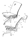
図1,2に示すように、椅子は、主要要素として、脚支柱2(ガスシリンダ)を有する
脚装置1、脚支柱2の上端に固定されたベース3、ベース3の上方に配置された座4、背もたれ5を備えている。背もたれ5に樹脂製のハンガー6を取付けている。脚1は放射状に延びる複数本の枝足(一部しか表示していない)を備えており、各枝足の先端にはキャスタを設けている。ベース3に背支持フレーム7が後傾動自在に連結されている。
(1). Outline of chair-Hanger and its mounting structure As shown in Figs. 1 and 2, the chair is fixed to the leg device 1 having the leg strut 2 (gas cylinder) as the main elements and to the upper end of the
背もたれ5は、バックフレーム8にメッシュ状で可撓性を有するサポートシート9を張った構造になっている。バックフレーム8は樹脂の成形品であり、上下方向に長く延びる左右サイドメンバー10と、左右サイドメンバー10の上端に繋がったアッパーメンバー11と、左右サイドメンバー10の下端に繋がったロアメンバー(図示せず)とから成っている。従って、バックフレーム8は正面視で略四角形の形態を成している。そして、背支持フレーム7の後端に支柱部7aを設け、この支柱部7aにバックフレーム8のサイドメンバー10をねじで締結している。
The
例えば図5(A)(C)に示すように、バックフレーム8の外周(各メンバーの外面)には長溝12が形成されている一方、サポートシート9の外周縁には帯状の縁部材13が固定されており、縁部材13を長溝12に嵌め入れている。従って、サポートシート9はバックフレーム8の前端面に重なっている。
For example, as shown in FIGS. 5A and 5C, a
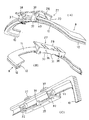
ハンガー6は、衣服やタオルなどの物品を掛ける作用横長のバー部15と、このバー部15から下向きに延びる左右一対の足体16とで構成されている。足体16はバー部15の左右中間に近い部分から下向きに延びて左右外側に広がっており、足体16の下端部がバックフレーム8におけるサイドメンバー10の内側面にビス17で固定されている。ハンガー6の足体16は、サイドメンバー10のうち上端に近い部分に固定されている。
The
図4及び図5(C)に明瞭に示すように、バックフレーム8におけるサイドメンバー10の内側面には、上側寄りの範囲に、前方及び内側に開口した凹所18が形成されており、この凹所18の下部にハンガー6の足体16が固定されている。凹所18は内側面18aと背面18bとを有しており、背面18bはサイドメンバー10の内側縁18cに連続している。
As clearly shown in FIG. 4 and FIG. 5C, a
一方、ハンガー6における足体16の下端面は、凹所18にきっちり嵌まると共にサイドメンバー10の内側縁18cにも重なるように形成されている。すなわち、足体16の下端面は、凹所18の内側面18aに重なる第1面16aと、凹所18の背面18bに重なる第2面16bと、サイドメンバー10の内側縁18cに重なる第3面16cとを有している。このため、全体として段違いのような外観を呈している。
On the other hand, the lower end surface of the
そして、バックフレーム8のサイドメンバー10に、前向きに開口したナット保持穴19と、ナット保持穴19に連通して凹所18の内側面18aに開口したビス穴20とを設けて、ナット保持穴19にナット21を回転不能に嵌め込んでいる。他方、ハンガー6における足体16の下端部には、ビス17が嵌まる取付け穴22を設けている。ハンガー6の足体16は平面視で内側に行くほど後ろにずれるように傾斜している一方、ビス17はおおむね左右横長の姿勢になっており、そこで、足体16の前面に座ぐり溝23を形成している。
Then, the
足体16の下端面のうち取付け穴22の下方部には、第1面16aと第2面16bとに跨がって延びる突起24を設けている一方、サイドメンバー10の凹所18には、突起24が嵌まる係合溝25を形成している。足体16の下端面がサイドメンバー10の凹所18と内側縁18cとに重なっていることに加えて、足体16の突起24がサイドメンバー10の係合溝25に嵌合しているため、足体16はサイドメンバー10に対してしっかりと固定されている。
A
また、既述のようにビス17の頭は足体16の前面に形成した座ぐり溝23に位置しており、このためビス17の頭を椅子の後ろから視認することはできず、他方、足体16の手前にはサポートシート9が配置されているため、ビス17の頭は前からも視認できない(或いは視認し難い。)。このため、ハンガー6は恰もサイドメンバー10に一体成形されているかのような外観を呈することができ、このため美感に優れている。また、ナット保持穴19も全く又は殆ど視認できず、この面でも美感に優れている。
Further, as described above, the head of the
ハンガー6の足体16は複数本のビスでサイドメンバー10に固定することも可能である。また、突起24と係合溝25との組み合わせのような位置決め手段は複数対設けることも可能である。更に、凹所18は内側のみに開口した形態(底面と前面と背面とを有する形態)にすることも可能である。また、左右の足体16を1本に収束してこれをバー部15に連接することも可能である。
The
(2).ヘッドレストの取付け構造
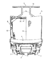
図6以下の図面に示すように、バックフレーム8のアッパーメンバー11にヘッドレスト27を取り付けることが可能である。この点を次に説明する。ヘッドレスト27は樹脂製の基板28を有している。基板28はアッパーメンバー11の左右長さと同じ程度の左右巾寸法に設定されており(左右巾は任意に設定できる)、平面視では前向き凹状に湾曲して側面視では前向き凸状に湾曲している。そして、図6(C)に示すように、基板28の前面にクッション材29を張っている。クッション材29はクロス等の表皮材で覆われている。
(2). Headrest attachment structure As shown in the drawings in FIG. 6 and subsequent figures, the
基板28の下部はアッパーメンバー11の後ろに位置しており、その下端にはアッパーメンバー11の下側に位置した前向き張り出し部30を前向きに突設している。前向き張り出し部30のうち左右中間部にアッパーメンバー11に下方から嵌合するセンター受け部31を設け、前向き張り出し部30のうち左右両端寄り部位には、アッパーメンバー11が載るサイド受け部32を設けている。
A lower portion of the
センター受け部31には、アッパーメンバー11を嵌合させるため、側面視で上向きに開口した係合溝33を設けている。一方、アッパーメンバー11には、サイド受け部32が嵌合する左右一対の切欠き溝34を形成しており、このため、基板28が前後及び左右にずれ不能に保持されている。
The
基板28の下部及び前向き張り出し部30には、センター受け部31とサイド受け部32との間に位置してアッパーメンバー11の後面に重なるリア支持部35を一体に設けており、リア支持部35にはビス穴37が上下に貫通している。そして、リア支持部35の箇所においてアッパーメンバー11に上からクランプ体37を重ねており、クランプ体37に形成したナット保持穴38にナット(図示せず)を回転不能に嵌め込み、ビス穴36に下方から挿通したビス(図示せず)をナットにねじ込むことにより、クランプ体37と前向き張り出し部30とでアッパーメンバー11を挟持している。
A
例えば図7(A)から理解できるように、クランプ体37にはアッパーメンバー11に上から嵌合する凹所38が形成されており、かつ、凹所39にはアッパーメンバー11の長溝12に嵌まるリブ40を形成している。リブ40はサポートシート9を押圧した状態で長溝12に嵌まることになる。
For example, as can be understood from FIG. 7A, the
さて、特許文献2はアッパーメンバー11を上下から挟持しているが、特許文献2ではハンガー6の左右位置を位置決めする機能は備えておらず、このため、ハンガーの左右位置が正確に位置決めされないおそれがある。また、特許文献2はアッパーメンバーをサポ
ートシートの後ろ側において挟持するものであるため、挟持強度を高くできない可能性がある。
これに対して本実施形態では、アッパーメンバー11に設けた切欠き溝34で左右位置が正確に位置決めされ、また、アッパーメンバー11の全体を上下から挟持するものであるため、固定強度にも優れている。なお、本実施形態ではハンガー6とヘッドレスト27とをバックフレーム8に併せて取り付けることができる。ハンガー6はサイドメンバー10に固定しているため、ヘッドレスト27がアッパーメンバー11の背面に沿って左右に長く延びていても、ハンガー6の取付けには全く支障はない。この点も本願発明の利点の一つであると言える。
On the other hand, in the present embodiment, the left and right positions are accurately positioned by the
本願発明は、特許文献1のようにバックフレーム8で背フレームを支持しているタイプの椅子にも適用できる。また、サポート体はメッシュのようなサポートシートに限定されるものではなく、サポート体として樹脂製背板(インナーシェル)を使用することも可能である(この場合は前面にクッション材を張ってもよい。)。
The present invention can also be applied to a chair of the type in which a back frame is supported by a
本願発明は椅子に適用して有用性を発揮する。従って産業上利用できる。 The present invention is useful when applied to a chair. Therefore, it can be used industrially.
5 背もたれ
6 ハンガー
8 バックフレーム
9 サポート体の一例としてのサポートシート
10 サイドメンバー
11 アッパーメンバー
15 ハンガーを構成するバー部
16 ハンガーを構成する足体
17 ビス
18 サイドメンバーの凹所
27 ヘッドレスト
DESCRIPTION OF
Claims (1)
前記背もたれは、着座者の体圧を支持するサポート体が直接に又は間接的に取付けられたバックフレームを有しており、前記バックフレームは、上下長手の左右サイドメンバーとその上端に繋がった左右横長のアッパーメンバーとを有する形態である一方、
前記ハンガーは、前記バックフレームのサイドメンバーに固定された左右の足体と、前記足体の上端に設けた左右横長のバー部とを有している、
椅子。 It has a backrest and a hanger attached to it,
The backrest includes a back frame to which a support body that supports the body pressure of a seated person is directly or indirectly attached, and the back frame includes left and right side members that are vertically long and connected to the upper end thereof. While it is a form having a horizontally long upper member,
The hanger has left and right feet fixed to the side members of the back frame, and left and right horizontally long bar portions provided at the upper ends of the feet.
Chair.
Priority Applications (1)
| Application Number | Priority Date | Filing Date | Title |
|---|---|---|---|
| JP2014059725A JP2014111219A (en) | 2014-03-24 | 2014-03-24 | Chair |
Applications Claiming Priority (1)
| Application Number | Priority Date | Filing Date | Title |
|---|---|---|---|
| JP2014059725A JP2014111219A (en) | 2014-03-24 | 2014-03-24 | Chair |
Related Parent Applications (1)
| Application Number | Title | Priority Date | Filing Date |
|---|---|---|---|
| JP2009295339A Division JP2011131007A (en) | 2009-12-25 | 2009-12-25 | Chair |
Related Child Applications (1)
| Application Number | Title | Priority Date | Filing Date |
|---|---|---|---|
| JP2015094627A Division JP2015134289A (en) | 2015-05-07 | 2015-05-07 | chair |
Publications (2)
| Publication Number | Publication Date |
|---|---|
| JP2014111219A true JP2014111219A (en) | 2014-06-19 |
| JP2014111219A5 JP2014111219A5 (en) | 2014-08-14 |
Family
ID=51168787
Family Applications (1)
| Application Number | Title | Priority Date | Filing Date |
|---|---|---|---|
| JP2014059725A Pending JP2014111219A (en) | 2014-03-24 | 2014-03-24 | Chair |
Country Status (1)
| Country | Link |
|---|---|
| JP (1) | JP2014111219A (en) |
Citations (1)
| Publication number | Priority date | Publication date | Assignee | Title |
|---|---|---|---|---|
| JP2008104521A (en) * | 2006-10-23 | 2008-05-08 | Kokuyo Co Ltd | Chair and back |
-
2014
- 2014-03-24 JP JP2014059725A patent/JP2014111219A/en active Pending
Patent Citations (1)
| Publication number | Priority date | Publication date | Assignee | Title |
|---|---|---|---|---|
| JP2008104521A (en) * | 2006-10-23 | 2008-05-08 | Kokuyo Co Ltd | Chair and back |
Similar Documents
| Publication | Publication Date | Title |
|---|---|---|
| JP2011131019A (en) | Chair | |
| JP2012090788A (en) | Chair | |
| USD791493S1 (en) | Arm chair | |
| USD799877S1 (en) | Lumbar support frame | |
| JP2015134289A (en) | chair | |
| JP2011131007A (en) | Chair | |
| JP2008237451A (en) | Cover installation structure for backboard of chair | |
| JP2014111219A (en) | Chair | |
| JP2015134289A5 (en) | ||
| JP2015013113A (en) | Chair | |
| JP5945114B2 (en) | Chair and optional items attached to it | |
| JP2014111219A5 (en) | ||
| JP2006187537A (en) | Leg frame structure of chair | |
| JP6257073B2 (en) | Chair | |
| JP4731753B2 (en) | Upholstery mounting structure for chairs | |
| TWI543734B (en) | Improved back | |
| JP5989755B2 (en) | Chair back | |
| JP2013106694A (en) | Chair | |
| JP4987066B2 (en) | Chair and back cover | |
| JP6001895B2 (en) | Chair backrest mounting structure | |
| JP5000631B2 (en) | Chair with hanger | |
| JP2014128741A (en) | Armrest device for chair | |
| JP7054999B2 (en) | Chair | |
| JP4222793B2 (en) | Chairs & chair covers | |
| JP2011092538A (en) | Back plate unit and backrest for chairs |
Legal Events
| Date | Code | Title | Description |
|---|---|---|---|
| A621 | Written request for application examination |
Free format text: JAPANESE INTERMEDIATE CODE: A621 Effective date: 20140324 |
|
| A521 | Written amendment |
Free format text: JAPANESE INTERMEDIATE CODE: A523 Effective date: 20140701 |
|
| A977 | Report on retrieval |
Free format text: JAPANESE INTERMEDIATE CODE: A971007 Effective date: 20150206 |
|
| A131 | Notification of reasons for refusal |
Free format text: JAPANESE INTERMEDIATE CODE: A131 Effective date: 20150304 |
|
| A02 | Decision of refusal |
Free format text: JAPANESE INTERMEDIATE CODE: A02 Effective date: 20150701 |