JP2014104626A - Apparatus for orienting/piling wood strand - Google Patents
Apparatus for orienting/piling wood strand Download PDFInfo
- Publication number
- JP2014104626A JP2014104626A JP2012257867A JP2012257867A JP2014104626A JP 2014104626 A JP2014104626 A JP 2014104626A JP 2012257867 A JP2012257867 A JP 2012257867A JP 2012257867 A JP2012257867 A JP 2012257867A JP 2014104626 A JP2014104626 A JP 2014104626A
- Authority
- JP
- Japan
- Prior art keywords
- wood
- orientation
- disks
- strands
- wood strands
- Prior art date
- Legal status (The legal status is an assumption and is not a legal conclusion. Google has not performed a legal analysis and makes no representation as to the accuracy of the status listed.)
- Pending
Links
Images


Abstract
Description
本発明は、厚さ、幅、長さの異なる木質ストランドを低コストで配向させることができる木質材片の配向積層装置に関する。 The present invention relates to an apparatus for orienting and laminating wood material pieces capable of orienting wood strands having different thicknesses, widths and lengths at low cost.
木質材片を、結合剤を用いて結合した極めて高い機械的強度を有し、構造材としても使用することができるものが存在する。このような木質系複合材料では、木質材片を、木質材片の繊維方向(異方性材料の高強度方向)と同方向に配向させることにより、その繊維方向の機械的強度を飛躍的に向上させている。
このような木質系複合材料の製造では、まず、木質材片に結合剤を付着した後、この結合剤が付着した木質材片を積層した積層マットを作製する。得られる木質系複合材料が高い機械的強度を発現するためには、積層マットにおいて木質材片がその繊維方向に充分に配向していることが極めて重要である。
There is one that has a very high mechanical strength in which a piece of wood is bonded using a binder and can also be used as a structural material. In such a wood-based composite material, the mechanical strength in the fiber direction is dramatically improved by orienting the wood material piece in the same direction as the fiber direction of the wood material piece (high strength direction of the anisotropic material). It is improving.
In the manufacture of such a wood-based composite material, first, a binder is attached to a piece of wood material, and then a laminated mat in which the pieces of wood material to which the binder is attached is laminated. In order for the obtained wood-based composite material to exhibit high mechanical strength, it is extremely important that the wood material pieces are sufficiently oriented in the fiber direction in the laminated mat.
木質材片の配向積層装置としては、結合剤が付着した木質材片を自然落下させ、配向板の間を通過させて配向させる原理を利用した種々の装置が考案されている。例えば、特許文献1〜3には、同軸上で複数枚の円盤を、一定間隔をおいて配置し、円盤を回転させながらその円盤同士の間に結合剤が付着した木質材片を通過させることによって木質材片を配向させる装置が開示されている。 As an apparatus for orienting and laminating wooden material pieces, various apparatuses have been devised that use the principle of allowing a wooden material piece to which a binder is attached to fall naturally and passing it between alignment plates for orientation. For example, in Patent Documents 1 to 3, a plurality of disks are arranged on the same axis at regular intervals, and a wooden material piece having a binder attached between the disks is passed while rotating the disks. Discloses an apparatus for orienting a piece of wood.
木質材片のなかでも、原木から切削機によって切削する等によって得られた木質ストランドからは、従来用いられてきた木質チップに比べ、軽量で機械的強度の高い木質系複合材料が得られる。このような木質ストランドは、厚さのばらつきは小さいものの、幅や長さのばらつきが大きく、従来の木質チップの配向に用いていた配向積層装置にそのまま供すると、1軸方向に充分に配向させることができないという問題があった。そのため、配向積層装置に供する前に予め木質ストランドの分級を行う必要があるが、分級を行うことにより、コストが高くなったり材料歩留まりが落ちたりするという問題があった。 Among wood pieces, a wood-based composite material that is lighter and has higher mechanical strength than wood chips that have been conventionally used can be obtained from wood strands obtained by cutting raw wood with a cutting machine. Such a wood strand has a small variation in thickness but a large variation in width and length, and when used as it is in an orientation laminating apparatus used for orientation of conventional wood chips, it is sufficiently oriented in a uniaxial direction. There was a problem that I could not. For this reason, it is necessary to classify the wood strands before use in the orientation laminating apparatus, but there are problems that the classification increases the cost and the material yield decreases.
本発明は、厚さ、幅、長さの異なる木質ストランドを低コストで配向させることができる木質ストランドの配向積層装置を提供することを目的とする。 An object of the present invention is to provide an oriented lamination apparatus for wood strands that can orient wood strands having different thicknesses, widths, and lengths at low cost.
本発明は、回転する円盤間に木質ストランドを落下させることにより木質ストランドを略平行に揃える配向部と、該配向部に木質ストランドを供給する供給部と、該配向部から落下し積層した木質ストランドを搬送する搬送部とを有する木質ストランドの配向積層装置であって、上記配向部は、平行な複数の回転軸と各回転軸の軸方向に複数の円盤とを有し、隣り合う円盤の間隔は10〜60mmであり、上記供給部は、木質ストランドを散布することにより上記配向部全体に木質ストランドを供給する木質ストランドの配向積層装置である。
以下に本発明を詳述する。
The present invention relates to an orientation unit that aligns wood strands substantially in parallel by dropping the wood strand between rotating disks, a supply unit that supplies the wood strand to the orientation unit, and a wood strand that is dropped from the orientation unit and stacked. An orientation laminating device for a wood strand having a transporting section that transports a plurality of rotating shafts in parallel and a plurality of disks in the axial direction of each rotating shaft, and an interval between adjacent disks Is 10 to 60 mm, and the supply unit is a wood strand orientation laminating device for supplying wood strands to the whole orientation portion by spraying wood strands.
The present invention is described in detail below.
本発明者らは、木質ストランドを散布することにより配向部全体に木質ストランドを供給し、かつ、配向部における隣り合う円盤の間隔が特定の範囲である木質ストランドの配向積層装置を用いることにより、厚さ、幅、長さの異なる木質ストランドを低コストで配向させることができることを見出し、本発明を完成させるに至った。
なお、本明細書において上記「木質ストランド」とは、木材を細かく削って得た、薄く細長い木片を意味する。
The present inventors supply wood strands to the entire orientation portion by spraying the wood strands, and by using an orientation laminating apparatus for wood strands in which the interval between adjacent disks in the orientation portion is in a specific range, The inventors have found that wood strands having different thicknesses, widths, and lengths can be oriented at low cost, and have completed the present invention.
In the present specification, the “woody strand” means a thin and thin piece of wood obtained by finely cutting wood.
上記木質ストランドとなる原料材の樹種としては、スギ、ヒノキ、マツ、スプルース、パイン、ファー等の針葉樹や、ラワン、ポプラ、アスペン、ファルカタ等の広葉樹が挙げられる。また、これらの森林から生産される植物材料だけでなく、竹、コウリャン等の森林以外で生産される植物材料も用いることができる。これらの樹種は単独であってもよいし、二種以上を併用してもよい。
原料材に利用できる形態としては、例えば、上記樹種の丸太、間伐材等の原木や、工場や住宅建築現場で発生する端材や、部材輸送後に廃棄される廃パレット材や、建築解体時に発生する解体廃材等が挙げられる。
なかでも、特に軽量で高強度の木質系複合材料が得られることから、密度0.5g/cm3以下の樹種が好適であり、密度0.4g/cm3以下のもの、例えば、スギ、アスペン、ファルカタ等がより好適である。
Examples of the tree species of the raw material used as the wood strand include conifers such as cedar, cypress, pine, spruce, pine, and fur, and broad-leaved trees such as lauan, poplar, aspen, and falkata. Moreover, not only plant materials produced from these forests, but also plant materials produced outside forests such as bamboo and cuolian can be used. These tree species may be single, and may use 2 or more types together.
Available forms for raw materials include, for example, logs of the above-mentioned tree species, thinned wood, scraps generated at factories and residential construction sites, waste pallet materials discarded after transportation of components, and generated at the time of building demolition Dismantled scrap materials and the like.
In particular, since a light-weight and high-strength woody composite material can be obtained, a tree species having a density of 0.5 g / cm 3 or less is preferable, and a tree species having a density of 0.4 g / cm 3 or less, such as cedar, aspen, etc. Falkata and the like are more preferable.
上記原料材を木質ストランドにする加工方法としては、例えば、スライサーでベニア加工したものをロータリーカッターによって短冊状にする方法や、フレーカーの回転刃によって丸太を切削して木質ストランドにする方法等が挙げられる。 Examples of the processing method for converting the raw material into a wood strand include, for example, a method in which a veneer processed with a slicer is formed into a strip shape by a rotary cutter, a method in which a log is cut into a wood strand by a rotary blade of a flaker, and the like. It is done.
上記木質ストランドは、厚さが0.1〜1.0mm、繊維方向長さが20mm以上、平均長さ/厚さが100〜500、平均長さ/幅が5〜30であるものが好ましい。厚さ、幅、長さがこの範囲内であれば、厚さ、幅、長さにばらつきがあっても木質ストランドを本発明の木質ストランドの配向積層装置を用いて充分に配向させることができ、軽量で機械的強度の高い木質系複合材料を得ることができる。より好ましくは、厚さが0.1〜0.8mmが90%以上、繊維方向長さが40〜70mmでかつ、平均値60mmに対し±20%の範囲内にある木質ストランドが80%以上、平均長さ/厚さが100〜300、平均長さ/幅が10〜20である。 The wood strand preferably has a thickness of 0.1 to 1.0 mm, a fiber direction length of 20 mm or more, an average length / thickness of 100 to 500, and an average length / width of 5 to 30. If the thickness, width and length are within this range, the wood strand can be sufficiently oriented using the wood strand orientation laminating apparatus of the present invention even if the thickness, width and length vary. A wood-based composite material that is lightweight and has high mechanical strength can be obtained. More preferably, the wood strands having a thickness of 0.1 to 0.8 mm of 90% or more, a fiber direction length of 40 to 70 mm, and within a range of ± 20% with respect to an average value of 60 mm are 80% or more, The average length / thickness is 100 to 300, and the average length / width is 10 to 20.
上記木質ストランドは、含水率を15%以下に調整してから、本発明の木質ストランドの配向積層装置に供することが好ましい。含水率を15%以下、より好ましくは5%以下に調整することにより、生産時の木質系複合材料の品質バラツキを小さくすることができる。
上記木質ストランドの含水率を15%以下に調整する方法としては、例えば、温調したオーブン中に一定時間木質ストランドを放置する方法等が挙げられる。例えば、105℃のオーブン中に24時間放置すると、木質ストランドの含水率はほぼ5%以下になる。
It is preferable that the wood strand is adjusted to a moisture content of 15% or less and then provided to the wood strand orientation laminating apparatus of the present invention. By adjusting the water content to 15% or less, more preferably 5% or less, it is possible to reduce the quality variation of the woody composite material during production.
Examples of the method for adjusting the moisture content of the wood strand to 15% or less include a method of leaving the wood strand for a certain time in a temperature-controlled oven. For example, when left in an oven at 105 ° C. for 24 hours, the moisture content of the wood strand becomes approximately 5% or less.
上記木質ストランドには、通常、本発明の木質ストランドの配向積層装置に供される前に結合剤が付着される。
上記結合剤としては、例えば、フェノール樹脂、ユリア樹脂、メラミン樹脂、イソシアネート樹脂、酢酸ビニル系樹脂等の熱硬化型樹脂や熱可塑型樹脂系の接着剤や、天然物成分又は天然物から精製、抽出、変性等によって得られた天然物由来の接着剤等の、合板やパーティクルボード等に用いられる従来公知の木材工業用接着剤が挙げられる。これらの結合剤は単独で用いてもよく、2種以上を併用してもよい。
The wood strand is usually attached with a binder before being provided to the wood strand orientation laminating apparatus of the present invention.
Examples of the binder include, for example, a thermosetting resin such as a phenol resin, a urea resin, a melamine resin, an isocyanate resin, and a vinyl acetate resin, a thermoplastic resin-based adhesive, and a purification from a natural product component or natural product The conventionally well-known adhesive for wood industry used for plywood, particle board, etc., such as an adhesive derived from a natural product obtained by extraction, modification or the like. These binders may be used independently and may use 2 or more types together.
上記天然物由来の接着剤としては、具体的には例えば、ゼラチン、カゼイングルー、大豆グルー、にかわ、アルブミン等のタンパク質系接着剤や、でんぷん、デキストリン、米糊、グルコマンナンなどのデンプン系接着剤や、キチン・キトサン等の動物系接着剤や、セルロース系接着剤、リグニン系接着剤、タンニン系接着剤等が挙げられる。 Specific examples of the natural product-derived adhesive include protein adhesives such as gelatin, casein glue, soybean glue, glue, and albumin, and starch adhesives such as starch, dextrin, rice paste, and glucomannan. And animal adhesives such as chitin and chitosan, cellulose adhesives, lignin adhesives, tannin adhesives, and the like.
上記結合剤は、木質ストランドに対し1〜20重量%の範囲で付着させることが好ましい。上記結合剤の付着量が1重量%未満であると、接着が不充分となり、20重量%を超えて付着させても材料コストが嵩む割に接着性能が上がらず、かえって釘打ち性能が低下したり、外観が木質的でなくなったりする等の問題が生じる。 The binder is preferably attached in the range of 1 to 20% by weight with respect to the wood strand. If the adhesion amount of the binder is less than 1% by weight, the adhesion becomes insufficient, and even if the adhesion amount exceeds 20% by weight, the adhesion performance does not increase for the increased material cost, but the nailing performance decreases. Or the appearance may not be woody.
上記木質ストランドに結合剤を付着させる方法としては、例えば、上記結合剤が液状である場合には、上記木質ストランドに噴霧する方法や、上記木質ストランドと撹拌混合して予め木質ストランドに担持させた状態でフォーミング機に供給する方法等が挙げられる。また、上記結合剤が粉末状である場合には、上記木質ストランドと攪拌混合して予め木質ストランドに担持させた状態でフォーミング機に供給する方法等が挙げられる。 As a method of attaching the binder to the wood strand, for example, when the binder is in a liquid state, a method of spraying the wood strand, or stirring and mixing with the wood strand and supporting the wood strand in advance. The method of supplying to a forming machine in a state is mentioned. Moreover, when the said binder is a powder form, the method etc. with which it stirs and mixes with the said wood strand, and is previously carry | supported by the wood strand, and are supplied to a forming machine etc. are mentioned.
本発明の木質ストランドの配向積層装置は、回転する円盤間に木質ストランドを落下させることにより木質ストランドを略平行に揃える配向部と、該配向部に木質ストランドを供給する供給部と、該配向部から落下し積層した木質ストランドを搬送する搬送部とを有する。 An orientation laminating apparatus for wood strands according to the present invention includes an orientation section that aligns wood strands in parallel by dropping the wood strand between rotating disks, a supply section that supplies the wood strand to the orientation section, and the orientation section. And a transport unit for transporting the laminated wood strands that have dropped and stacked.
上記配向部は、平行な複数の回転軸と各回転軸の軸方向に複数の円盤とを有する。回転する円盤間に木質ストランドを落下させることにより木質ストランドを略平行に揃えることができる。
なお、本明細書において、上記「略平行」とは、ある木質ストランドの長さ方向(長手方向)と別の木質ストランドの長さ方向との角度が24°以内であることを意味し、略平行に揃うことを「配向する」ともいう。
The orientation section includes a plurality of parallel rotation axes and a plurality of disks in the axial direction of each rotation axis. By dropping the wood strands between the rotating disks, the wood strands can be made substantially parallel.
In the present specification, the term “substantially parallel” means that the angle between the length direction (longitudinal direction) of one wood strand and the length direction of another wood strand is within 24 °, Alignment in parallel is also called “orientation”.
配向効率を高める観点から、各回転軸の円盤は、隣の回転軸の円盤間に配置されることが好ましく、隣の回転軸の円盤間の略中央に配置されることがより好ましい。 From the viewpoint of increasing the orientation efficiency, the disks of the respective rotating shafts are preferably disposed between the disks of the adjacent rotating shafts, and more preferably disposed substantially at the center between the disks of the adjacent rotating shafts.
隣り合う円盤の間隔の好ましい下限は10mm、好ましい上限は60mmである。隣り合う円盤の間隔が10mm未満であると、円盤間に落下せずに、円盤上に残ったり円盤間に詰まったりする木質ストランドが多くなる。隣り合う円盤の間隔が60mmを超えると、落下した木質ストランドの配向性が悪くなる。隣り合う円盤の間隔の好ましい上限は30mmである。
また、隣り合う円盤の間隔は、木質ストランドの幅に対して、5〜20mm大きいことが好ましい。
なお、本明細書において、上記「隣り合う円盤の間隔」とは、回転軸の軸方向の間隔を意味する。また、各回転軸の円盤が、隣の回転軸の円盤間に配置される場合、上記「隣り合う円盤の間隔」は、隣り合う回転軸の円盤の軸方向の間隔を意味する。
The preferable lower limit of the interval between adjacent disks is 10 mm, and the preferable upper limit is 60 mm. If the distance between adjacent disks is less than 10 mm, the number of wooden strands remaining on the disks or clogged between the disks increases without falling between the disks. When the interval between adjacent disks exceeds 60 mm, the orientation of the dropped wooden strands is deteriorated. A preferable upper limit of the interval between adjacent disks is 30 mm.
Moreover, it is preferable that the space | interval of an adjacent disk is 5-20 mm larger with respect to the width | variety of a wooden strand.
In the present specification, the “interval between adjacent disks” means an interval in the axial direction of the rotating shaft. Further, when the discs of the respective rotating shafts are arranged between the discs of the adjacent rotating shafts, the “interval between adjacent discs” means an interval in the axial direction of the discs of the adjacent rotating shafts.
隣り合う回転軸の円盤は、直径が異なっていてもよい。隣り合う回転軸の円盤の直径が異なることにより、木質ストランドが落下しやすくなり、供給量を増やすことができる。
具体的には、隣り合う回転軸の円盤の直径の差が10〜60mmであることが好ましい。
また、同一の回転軸において、直径が小さい円盤と直径が大きい円盤とを交互に配置していてもよい。直径が小さい円盤と直径が大きい円盤とを交互に配置することにより、木質ストランドを更に落下しやすくすることができる。
具体的には、直径の差が10〜60mmである円盤を交互に配置することが好ましい。
The disks of adjacent rotating shafts may have different diameters. When the diameters of the discs of the adjacent rotating shafts are different, the wood strands can easily fall and the supply amount can be increased.
Specifically, it is preferable that the difference between the diameters of the adjacent rotating shafts is 10 to 60 mm.
Further, on the same rotating shaft, disks having a small diameter and disks having a large diameter may be alternately arranged. By alternately arranging disks having a small diameter and disks having a large diameter, the wood strands can be further easily dropped.
Specifically, it is preferable to alternately arrange disks having a diameter difference of 10 to 60 mm.
円盤の回転数の好ましい下限は周速で1m/min、好ましい上限は20m/minである。円盤の回転数が1m/min未満であると、円盤上に木質ストランドがたまり、その上に更に木質ストランドが供給され、木質ストランドが落下しなくなることがある。円盤の回転数が20m/minを超えると、木質ストランドが落下せずに末端まで運ばれることが多くなることがある。円盤の回転数のより好ましい下限は3m/min、より好ましい上限は10m/minである。 The preferable lower limit of the rotational speed of the disk is 1 m / min at the peripheral speed, and the preferable upper limit is 20 m / min. When the rotational speed of the disk is less than 1 m / min, wood strands may accumulate on the disk, and further wood strands may be supplied on the wood strands, so that the wood strands may not fall. If the rotational speed of the disk exceeds 20 m / min, the wood strands are often carried to the end without falling. A more preferable lower limit of the rotational speed of the disk is 3 m / min, and a more preferable upper limit is 10 m / min.
上記配向部は、配向補助器具を有することが好ましい。上記配向補助器具は、円盤間に落下せずに円盤上に残り、円盤の回転に応じて円盤上を移動する木質ストランドと接触して該木質ストランドの方向を変化させ、該木質ストランドを円盤間に落下させる役割を有する。
上記配向補助器具の形状は、棒状、板状等、いずれの形状であってもよいが、棒状が好ましい。
The orientation portion preferably has an orientation assisting device. The orientation assisting tool does not fall between the disks, remains on the disks, changes the direction of the wooden strands in contact with the wooden strands moving on the disks according to the rotation of the disks, and the wooden strands are moved between the disks. Has the role of falling.
The shape of the orientation assisting device may be any shape such as a rod shape or a plate shape, but a rod shape is preferred.
上記供給部は、木質ストランドを散布することにより上記配向部全体に木質ストランドを供給する。木質ストランドを散布することにより、木質ストランドの供給位置を上記配向部全体に分散させることができ、円盤間に落下せずに円盤上に残ったり、円盤間に詰まったりする木質ストランドを少なくすることができる。 The supply unit supplies the wood strands to the entire orientation unit by spraying the wood strands. By spreading the wood strands, the supply position of the wood strands can be dispersed throughout the above-mentioned orientation part, and the wood strands remaining on the disks without being dropped between the disks or being clogged between the disks are reduced. Can do.
上記供給部は、木質ストランドを散布した際に飛散の程度の小さい木質ストランドを更に飛散させて配向部全体に供給する第2の散布機構を有することが好ましい。このような2段階の散布機構を有することにより、更に木質ストランドの供給位置を上記配向部全体に分散させることができる。 It is preferable that the supply unit has a second spraying mechanism that further scatters the wood strands having a small degree of scattering when the wood strands are sprayed and supplies the whole to the orientation unit. By having such a two-stage spraying mechanism, the supply position of the wood strands can be further dispersed throughout the orientation section.
木質ストランドを散布する方法としては、例えば、複数の突起を有するロール体により一定量の木質ストランドを掻き飛ばす方法、風力を利用して木質ストランドを吹き飛ばす方法等が挙げられる。 Examples of the method for spraying the wood strands include a method of scraping a certain amount of wood strands with a roll body having a plurality of protrusions, a method of blowing off the wood strands using wind power, and the like.
上記配向部から落下した木質ストランドは、配向したまま搬送部で積層され、搬送される。
上記搬送部での搬送手段としては、例えば、ベルトコンベア、コンベア上に載置したコール板等が挙げられる。
The wood strands dropped from the orientation section are stacked and transported in the transport section while being oriented.
As a conveyance means in the said conveyance part, the call board etc. which were mounted on the belt conveyor and the conveyor are mentioned, for example.
上記配向部の円盤と上記搬送部との間の距離(配向した木質ストランドの落下距離)の好ましい下限は1cm、好ましい上限は5cmである。上記配向部の円盤と上記搬送部との間の距離が1cm未満であると、搬送部に落下積層した木質ストランドが円盤と接触し、抵抗となってコンベア上を滑り、搬送されなくなる。更には円盤内に木質ストランドが詰まってしまうことがある。上記配向部の円盤と上記搬送部との間の距離が5cmを超えると、落下した木質ストランドの配向性が悪くなる。上記配向部の円盤と上記搬送部との間の距離のより好ましい下限は2cm、より好ましい上限は4cmである。 The preferred lower limit of the distance between the disk of the orientation part and the transport part (the falling distance of the oriented wood strand) is 1 cm, and the preferred upper limit is 5 cm. When the distance between the disk of the orientation part and the transport part is less than 1 cm, the wood strand dropped and laminated on the transport part comes into contact with the disk, becomes a resistance, slips on the conveyor, and is not transported. Furthermore, the wood strands may be clogged in the disk. When the distance between the disk of the said orientation part and the said conveyance part exceeds 5 cm, the orientation of the fallen wooden strand will worsen. The more preferable lower limit of the distance between the disk of the orientation section and the transport section is 2 cm, and the more preferable upper limit is 4 cm.
上記搬送部によって搬送された木質ストランドを、加熱圧縮する熱圧成形することにより、木質系複合材料を製造することができる。本発明の木質ストランドの配向積層装置を用いれば、原木から切削機によって切削して得られた木質ストランドでも充分配向させることができるため、軽量で機械的強度の高い木質系複合材料を得ることができる。 A wood-based composite material can be manufactured by hot-pressing the wood strands transported by the transport unit by heating and compressing. By using the wood strand orientation laminating apparatus of the present invention, it is possible to sufficiently orient even wood strands obtained by cutting from raw wood with a cutting machine. it can.
本発明によれば、厚さ、幅、長さの異なる木質ストランドを低コストで配向させることができる木質ストランドの配向積層装置を提供することができる。 ADVANTAGE OF THE INVENTION According to this invention, the orientation lamination apparatus of the wood strand which can orientate the wood strand from which thickness, width, and length differ at low cost can be provided.
以下に図面を用いて本発明の木質ストランドの配向積層装置を更に詳しく説明するが、本発明は、これら図面に示した実施形態のみに限定されない。 In the following, the oriented and laminated apparatus for wood strands of the present invention will be described in more detail with reference to the drawings. However, the present invention is not limited only to the embodiments shown in these drawings.
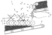
図1は、本発明の木質ストランドの配向積層装置の一例を示す斜視図であり、図2は、図1の木質ストランドの配向積層装置の側面図である。
図1及び図2に示したように、本発明の木質ストランドの配向積層装置1は、供給部2と、配向部3と、搬送部4とを有し、供給部2から配向部3へと供給された木質ストランド5は、搬送部4へ落下し、積層して搬送される。
FIG. 1 is a perspective view showing an example of an oriented laminating apparatus for wood strands of the present invention, and FIG. 2 is a side view of the oriented laminating apparatus for wood strands of FIG.
As shown in FIGS. 1 and 2, the wood strand oriented laminating apparatus 1 of the present invention has a
供給部2は、第1の散布機構A6と第2の散布機構B7との2段階の散布機構を有する。散布機構A6は、複数の突起を有する2つのロール体からなり、散布機構B7は、複数の板を備えたロール体からなる。まず、散布機構A6が高速回転することにより、木質ストランド5が掻き飛ばされる。このとき、飛散の程度の小さい木質ストランド5は、高速回転する散布機構B7上に落下し、散布機構B7により更に飛散される。このようにして供給部2から配向部3全体に木質ストランド5が分散して供給される。
The
配向部3は、平行な複数の回転軸8と各回転軸8の軸方向に複数の円盤9とを有する。円盤9は、供給部2から最も離れた位置にある回転軸8のもの以外は、図1、図2における反時計回りの方向に回転し、供給部2から最も離れた位置にある回転軸8のものは、図1、図2における時計回りに回転する。
配向部3に供給された木質ストランド5は、大部分がそのまま円盤9間から搬送部4へ落下するが、一部は円盤9間から落下せず、そのまま円盤9上に残る。円盤9上に残った木質ストランド5は、円盤9の回転に応じて円盤9上を移動する。配向部3には棒状の配向補助器具10が設けられており、円盤9上を移動する木質ストランド5が配向補助器具10と接触すると、該木質ストランド5の方向が変化し、該木質ストランド5を円盤9間に落下させることができる。配向補助器具10は、図2において矢印で示したように回転させることにより、木質ストランド5の落下効率を更に向上させることができる。
The
Most of the wood strand 5 supplied to the
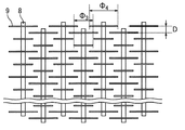
図3は、配向部における円盤の配置の一例を示す平面図である。
図3において、各回転軸8の円盤9は、隣の回転軸8の円盤9間に配置されている。隣り合う円盤9の間隔(隣り合う回転軸8の円盤9の軸方向の間隔)Dは10〜60mmであり、好ましくは10〜30mmとされる。Dがこの範囲であることで、厚さが0.1〜1.0mm、繊維方向長さが20mm以上、平均長さ/厚さが100〜500、平均長さ/幅が5〜30の範囲で大きさの異なる木質ストランド5を充分に配向させることができる。
FIG. 3 is a plan view showing an example of the arrangement of the disks in the orientation portion.
In FIG. 3, the
図4は、配向部における円盤の配置の別の一例を示す平面図である。
図4においても、図3と同様に、各回転軸8の円盤9は、隣の回転軸8の円盤9間に配置されており、隣り合う円盤9の間隔Dは10〜60mmであり、好ましくは10〜30mmとされる。図3では、隣り合う回転軸8の円盤9は、直径Φ1、Φ2がそれぞれ等しいものであるが、図4では、Φ2>Φ1となっている。このように隣り合う回転軸8の円盤9の直径が異なることにより、木質ストランド5が落下しやすくなり、供給量を増やすことができる。円盤9の直径Φ1、Φ2は、木質ストランド5の配向性が悪くならない範囲で変更できる。
FIG. 4 is a plan view showing another example of the arrangement of the disks in the orientation portion.
Also in FIG. 4, the
図5は、配向部における円盤の配置の別の一例を示す平面図である。
図5に示したように、同一の回転軸8において、円盤9の直径が小さい(Φ3)ものと大きい(Φ4)ものとを交互に配置することにより、木質ストランド5を更に落下しやすくすることができる。円盤9の直径Φ3、Φ4は、木質ストランド5の配向性が悪くならない範囲で変更できる。
FIG. 5 is a plan view showing another example of the arrangement of the disks in the orientation portion.
As shown in FIG. 5, the wood strands 5 can be more easily dropped by alternately arranging the small (Φ 3 ) and large (Φ 4 )
円盤9間から落下した木質ストランド5は、配向したまま搬送部4上に積層し、搬送される。図1及び図2では、搬送部4における搬送手段をベルトコンベアとしている。
The wood strands 5 dropped from between the
本発明によれば、厚さ、幅、長さの異なる木質ストランドを低コストで配向させることができる木質ストランドの配向積層装置を提供することができる。 ADVANTAGE OF THE INVENTION According to this invention, the orientation lamination apparatus of the wood strand which can orientate the wood strand from which thickness, width, and length differ at low cost can be provided.
1 木質ストランドの配向積層装置
2 供給部
3 配向部
4 搬送部
5 木質ストランド
6 散布機構A
7 散布機構B
8 回転軸
9 円盤
10 配向補助器具
DESCRIPTION OF SYMBOLS 1
7 Spraying mechanism B
8 Rotating
Claims (6)
前記配向部は、平行な複数の回転軸と各回転軸の軸方向に複数の円盤とを有し、隣り合う円盤の間隔は10〜60mmであり、
前記供給部は、木質ストランドを散布することにより前記配向部全体に木質ストランドを供給する
ことを特徴とする木質ストランドの配向積層装置。 An orientation unit that drops the wood strands between rotating discs to align the wood strands substantially in parallel, a supply unit that supplies the wood strands to the orientation unit, and a transport that transports the wood strands that have fallen from the orientation unit and stacked. An orientation laminating device for wood strands having a portion,
The orientation portion has a plurality of parallel rotation axes and a plurality of disks in the axial direction of each rotation axis, and the interval between adjacent disks is 10 to 60 mm,
The said supply part supplies the wood strand to the said whole orientation part by spraying a wood strand, The oriented lamination apparatus of the wood strand characterized by the above-mentioned.
Priority Applications (1)
| Application Number | Priority Date | Filing Date | Title |
|---|---|---|---|
| JP2012257867A JP2014104626A (en) | 2012-11-26 | 2012-11-26 | Apparatus for orienting/piling wood strand |
Applications Claiming Priority (1)
| Application Number | Priority Date | Filing Date | Title |
|---|---|---|---|
| JP2012257867A JP2014104626A (en) | 2012-11-26 | 2012-11-26 | Apparatus for orienting/piling wood strand |
Publications (1)
| Publication Number | Publication Date |
|---|---|
| JP2014104626A true JP2014104626A (en) | 2014-06-09 |
Family
ID=51026531
Family Applications (1)
| Application Number | Title | Priority Date | Filing Date |
|---|---|---|---|
| JP2012257867A Pending JP2014104626A (en) | 2012-11-26 | 2012-11-26 | Apparatus for orienting/piling wood strand |
Country Status (1)
| Country | Link |
|---|---|
| JP (1) | JP2014104626A (en) |
Cited By (1)
| Publication number | Priority date | Publication date | Assignee | Title |
|---|---|---|---|---|
| CN109732722A (en) * | 2018-12-29 | 2019-05-10 | 湖北宝源木业有限公司 | It is provided with the wet flaking transmitting device of spray structure and the transmission method of wet flaking |
-
2012
- 2012-11-26 JP JP2012257867A patent/JP2014104626A/en active Pending
Cited By (1)
| Publication number | Priority date | Publication date | Assignee | Title |
|---|---|---|---|---|
| CN109732722A (en) * | 2018-12-29 | 2019-05-10 | 湖北宝源木业有限公司 | It is provided with the wet flaking transmitting device of spray structure and the transmission method of wet flaking |
Similar Documents
| Publication | Publication Date | Title |
|---|---|---|
| US5932038A (en) | Method of fabricating a straw panel, board, or beam | |
| EP3225370A1 (en) | Method and system for production of oriented structural shaving board | |
| US20170151688A1 (en) | Method of manufacturing a corrugated wood element, a corrugated wood element and its uses | |
| US11318636B2 (en) | Composite wood panels with corrugated cores and method of manufacturing same | |
| CN100462211C (en) | Apparatus for orienting and laminating binder-adhered wood chips and method of manufacturing wooden composite material | |
| JP3515099B2 (en) | Method for producing wood-based composite material | |
| JP2014104626A (en) | Apparatus for orienting/piling wood strand | |
| JP2019147299A (en) | Manufacturing method of woody composite material and orientation lamination device of ligneous strand | |
| US7871701B2 (en) | Chipboard | |
| JP4619018B2 (en) | Wood chip orientation laminating apparatus and orientation laminating method | |
| JP7148771B2 (en) | materials | |
| JP3338030B2 (en) | Method for producing wood-based structural material | |
| JP2007314945A (en) | Wood-based structural material | |
| JP2009202380A (en) | Manufacturing method of orientated laminate of wood chip | |
| JP3924196B2 (en) | Forming type and method of manufacturing laminated mat using the forming type | |
| JP4038186B2 (en) | Wood chip orientation laminating equipment | |
| JP2012066449A (en) | Woody composite material | |
| JP2004322545A (en) | Selecting method of length of woody material piece | |
| JP4351604B2 (en) | Oriented laminating equipment for wooden pieces | |
| JP2012051169A (en) | Oriented strand board | |
| JP2004322547A (en) | Manufacturing method for wooden material piece laminated mat | |
| JP2005096403A (en) | Woody chip orienting/laminating apparatus | |
| CN102371609A (en) | Shaving board | |
| JP2004066644A (en) | Method and apparatus for orienting/laminating woody material piece | |
| JP2011167902A (en) | Method for dividing oriented woody thermocompression molded material |