JP2014103670A - Three dimensional image display system and adjusting method thereof - Google Patents
Three dimensional image display system and adjusting method thereof Download PDFInfo
- Publication number
- JP2014103670A JP2014103670A JP2013238670A JP2013238670A JP2014103670A JP 2014103670 A JP2014103670 A JP 2014103670A JP 2013238670 A JP2013238670 A JP 2013238670A JP 2013238670 A JP2013238670 A JP 2013238670A JP 2014103670 A JP2014103670 A JP 2014103670A
- Authority
- JP
- Japan
- Prior art keywords
- adjustment
- viewing angle
- information
- display
- unit
- Prior art date
- Legal status (The legal status is an assumption and is not a legal conclusion. Google has not performed a legal analysis and makes no representation as to the accuracy of the status listed.)
- Pending
Links
Images


Classifications
-
- H—ELECTRICITY
- H04—ELECTRIC COMMUNICATION TECHNIQUE
- H04N—PICTORIAL COMMUNICATION, e.g. TELEVISION
- H04N13/00—Stereoscopic video systems; Multi-view video systems; Details thereof
- H04N13/30—Image reproducers
- H04N13/349—Multi-view displays for displaying three or more geometrical viewpoints without viewer tracking
-
- G—PHYSICS
- G02—OPTICS
- G02B—OPTICAL ELEMENTS, SYSTEMS OR APPARATUS
- G02B30/00—Optical systems or apparatus for producing three-dimensional [3D] effects, e.g. stereoscopic images
- G02B30/20—Optical systems or apparatus for producing three-dimensional [3D] effects, e.g. stereoscopic images by providing first and second parallax images to an observer's left and right eyes
- G02B30/26—Optical systems or apparatus for producing three-dimensional [3D] effects, e.g. stereoscopic images by providing first and second parallax images to an observer's left and right eyes of the autostereoscopic type
- G02B30/27—Optical systems or apparatus for producing three-dimensional [3D] effects, e.g. stereoscopic images by providing first and second parallax images to an observer's left and right eyes of the autostereoscopic type involving lenticular arrays
- G02B30/28—Optical systems or apparatus for producing three-dimensional [3D] effects, e.g. stereoscopic images by providing first and second parallax images to an observer's left and right eyes of the autostereoscopic type involving lenticular arrays involving active lenticular arrays
-
- G—PHYSICS
- G06—COMPUTING OR CALCULATING; COUNTING
- G06T—IMAGE DATA PROCESSING OR GENERATION, IN GENERAL
- G06T19/00—Manipulating 3D models or images for computer graphics
- G06T19/20—Editing of 3D images, e.g. changing shapes or colours, aligning objects or positioning parts
-
- H—ELECTRICITY
- H04—ELECTRIC COMMUNICATION TECHNIQUE
- H04N—PICTORIAL COMMUNICATION, e.g. TELEVISION
- H04N13/00—Stereoscopic video systems; Multi-view video systems; Details thereof
- H04N13/10—Processing, recording or transmission of stereoscopic or multi-view image signals
- H04N13/106—Processing image signals
- H04N13/144—Processing image signals for flicker reduction
-
- H—ELECTRICITY
- H04—ELECTRIC COMMUNICATION TECHNIQUE
- H04N—PICTORIAL COMMUNICATION, e.g. TELEVISION
- H04N13/00—Stereoscopic video systems; Multi-view video systems; Details thereof
- H04N13/30—Image reproducers
- H04N13/356—Image reproducers having separate monoscopic and stereoscopic modes
Landscapes
- Engineering & Computer Science (AREA)
- Multimedia (AREA)
- Signal Processing (AREA)
- Physics & Mathematics (AREA)
- General Physics & Mathematics (AREA)
- Optics & Photonics (AREA)
- Computer Hardware Design (AREA)
- Computer Graphics (AREA)
- Architecture (AREA)
- General Engineering & Computer Science (AREA)
- Software Systems (AREA)
- Theoretical Computer Science (AREA)
- Controls And Circuits For Display Device (AREA)
- Testing, Inspecting, Measuring Of Stereoscopic Televisions And Televisions (AREA)
- Transforming Electric Information Into Light Information (AREA)
- Ultra Sonic Daignosis Equipment (AREA)
- Measuring And Recording Apparatus For Diagnosis (AREA)
Abstract
Description
本発明は、一般には三次元画像表示システム及びその調整方法に関し、より詳細には、調整ステップを実行可能な三次元画像表示システム及びその調整方法に関する。 The present invention generally relates to a three-dimensional image display system and an adjustment method thereof, and more particularly to a three-dimensional image display system capable of executing an adjustment step and an adjustment method thereof.
三次元(3D)ディスプレイは、閲覧者の2つの目のそれぞれに対し視差を有する画像を提供し、それらの画像が統合されて、閲覧者による立体感を生成するようにする。例えば、3D表示システムの動作方法は、特許文献1に記載されている。市場で入手可能な3D表示の大半は、眼鏡と併用され、信号送信及び信号同期、価格、重量、快適性等の点で多くの欠点を有する。したがって、裸眼3D(自動立体視)表示技術が、3D表示技術での将来の傾向である。
A three-dimensional (3D) display provides parallax images for each of the viewer's two eyes, and the images are integrated to generate a stereoscopic effect by the viewer. For example,
裸眼3Dディスプレイは主に2つの種類、すなわち、レンチキュラーレンズディスプレイ及び視差バリアディスプレイを有する。両タイプのディスプレイは、空間分布により立体画像を形成する。レンチキュラーレンズディスプレイは屈折の原理に基づく。レンチキュラーレンズは、左目画像及び右目画像が閲覧者の左目及び右目にそれぞれ正確に投射されるように、光を屈折させ、ディスプレイへの方向から逸らし、角度を持つように放射させる。視差バリアディスプレイは光遮蔽の原理に基づく。互いに交互になった複数のバリアエリア及び透過エリアにより形成される格子が、閲覧者の左目及び右目が格子を通して見る画像がそれぞれ、正確な左目画像及び右目画像であるように設計される。 There are two main types of naked-eye 3D displays: lenticular lens displays and parallax barrier displays. Both types of displays form a stereoscopic image by spatial distribution. Lenticular lens displays are based on the principle of refraction. The lenticular lens refracts light, deflects it away from the direction toward the display, and emits it at an angle so that the left eye image and right eye image are accurately projected to the viewer's left eye and right eye, respectively. The parallax barrier display is based on the principle of light shielding. The grid formed by a plurality of alternating barrier and transmissive areas is designed such that the images viewed by the viewer's left and right eyes through the grid are the correct left-eye and right-eye images, respectively.
空間分布を使用する裸眼3Dディスプレイは、所定の好ましい閲覧位置を有する。閲覧者が画像をこれらの位置から閲覧していない場合、閲覧者の左目は右目画像を見る場合があり、右目が左目画像を見る場合があり、かつこの逆が生じる場合がある。そのような状況下では、クロストークが生じ、立体視覚効果を妨げるおそれがある。加えて、裸眼3Dディスプレイがマルチビューディスプレイであると仮定する。閲覧者の左目及び右目が閲覧角度周期の境界を越えると(例えば、N個の閲覧角度があり、閲覧者の左目が(N−1)番目の画像からN番目の画像に移り、右目がN番目の画像から1番目の画像に移ると仮定する)、立体像は、閲覧者を不快にさせる大きな飛びを有するおそれがある。 A naked-eye 3D display using a spatial distribution has a predetermined preferred viewing position. If the viewer is not viewing images from these positions, the viewer's left eye may see the right eye image, the right eye may see the left eye image, and vice versa. Under such circumstances, crosstalk occurs, which may hinder stereoscopic vision effects. In addition, assume that the autostereoscopic 3D display is a multi-view display. When the viewer's left eye and right eye cross the boundary of the viewing angle cycle (for example, there are N viewing angles, the viewer's left eye moves from the (N-1) th image to the Nth image, and the right eye has N Assuming the transition from the first image to the first image), the stereoscopic image may have large jumps that make the viewer uncomfortable.
本発明は、三次元画像表示システム及びその調整方法に関する。三次元画像ディスプレイは、調整ステップにおいて計算結果を生成し、調整ステップにおいて取得される調整結果に従って計算結果を生成し、計算結果に従って調整された三次元画像を表示装置に出力し、ユーザーが未調整の三次元画像の閲覧から生じる不快さを経験しないようにする。 The present invention relates to a three-dimensional image display system and an adjustment method thereof. The 3D image display generates the calculation result in the adjustment step, generates the calculation result according to the adjustment result acquired in the adjustment step, outputs the 3D image adjusted according to the calculation result to the display device, and the user does not adjust Do not experience the discomfort resulting from viewing 3D images.
本発明の一実施形態によれば、三次元画像表示システムの三次元画像表示調整方法が開示される。本方法は、以下のステップ、すなわち、
調整パターンを表示装置に表示するステップと、
前記調整パターンに従って調整ステップを実行して調整結果を取得する、実行するステップと、
前記調整結果に従って計算結果を生成するステップと、
前記計算結果に従って調整された三次元画像を前記表示装置に出力するステップと、
を含む。
According to an embodiment of the present invention, a 3D image display adjustment method of a 3D image display system is disclosed. The method comprises the following steps:
Displaying the adjustment pattern on the display device;
Executing an adjustment step according to the adjustment pattern to obtain an adjustment result;
Generating a calculation result according to the adjustment result;
Outputting a three-dimensional image adjusted according to the calculation result to the display device;
including.
本発明の別の実施形態によれば、三次元画像表示システムが開示される。本システムは、表示装置及び処理装置を備える。表示ユニットを有する表示装置は、三次元画像及び調整パターンを表示する。前記表示ユニットに電気的に接続された処理装置は、前記調整パターンに従って調整ステップを実行して調整結果を取得し、該調整結果に従って計算結果を生成し、該計算結果に従って調整された三次元画像を前記表示ユニットに出力する。 According to another embodiment of the present invention, a three-dimensional image display system is disclosed. The system includes a display device and a processing device. A display device having a display unit displays a three-dimensional image and an adjustment pattern. A processing device electrically connected to the display unit executes an adjustment step according to the adjustment pattern to obtain an adjustment result, generates a calculation result according to the adjustment result, and a three-dimensional image adjusted according to the calculation result Is output to the display unit.
本発明の上記の態様及び他の態様は、好ましいが非限定的な実施形態の以下の詳細な説明に関してより良好に理解されるようになる。以下の説明は、添付の図面を参照して行われる。 The above and other aspects of the present invention will become better understood with regard to the following detailed description of the preferred but non-limiting embodiments. The following description is made with reference to the accompanying drawings.
第1の実施形態
図1Aは、本発明の一実施形態による三次元画像表示調整システム10の概略図を示す。図1Aを参照すると、三次元画像表示システム10は、2D/3D切り替え可能表示装置等の表示装置100を備える。表示装置100は、処理装置102、アクティブ化ユニット104、表示ユニット106、及び画像捕捉ユニット108を備える。処理装置102は、アクティブ化ユニット104、表示ユニット106、及び画像捕捉ユニット108を電気的に接続する。処理装置102は、記憶ユニット1020、信号生成ユニット1022、計算ユニット1024、及び駆動ユニット1026を備えることができる。駆動ユニット1026は、駆動信号を表示ユニット106に提供するために使用される。
First Embodiment FIG. 1A shows a schematic diagram of a three-dimensional image
本実施形態では、アクティブ化ユニット104は、表示装置の三次元画像表示機能をアクティブ化するアクティブ化ステップを実行することができる。例えば、アクティブ化ユニット104は押しボタン又はタッチボタンを備えることができ、ユーザーが押しボタン又はタッチボタンを押下する場合、表示装置の三次元画像表示機能をアクティブ化することができる。または、アクティブ化ユニット104は、遠隔コントローラーから受信される遠隔制御信号を用いて三次元画像表示機能をアクティブ化することができ、本発明はそれに限定されない。
In this embodiment, the
表示ユニット106は、光学制御モジュール(図示せず)及び表示モジュール(図示せず)を備えることができる。光学制御モジュール及び表示モジュールが一緒に組み立てられた後、バイアス電圧を、光学制御モジュールの両側に配置された電極に印加して、光学制御モジュールの表示媒体を調整し、透過モード及び光遮断モード等の異なる構成を生成し、切り替え可能な格子を形成することができる。したがって、表示装置10の2D/3D切り替え可能表示機能を達成することができる。
The
一実施形態では、2D/3D切り替え可能表示機能は、能動レンズを使用して達成することができる。光学制御モジュールは、レンズ層及び液晶パネル(TN液晶パネル等)により形成することができる。液晶パネルの設計は以下である:2D動作中、液晶パネルは、表示モジュールを貫く光が光学制御モジュールにより影響を受けず、通常通り2D画像を表示することができるように、レンズ層の屈折効果をオフセットすることができる。3D動作中、能動レンズはレンチキュラーレンズの効果を有する。別の実施形態では、光学制御モジュールは、通常のレンチキュラーレンズパッチ又は透過エリア及び光遮断エリアが互いに交互になる通常の格子パッチで置換することができ、本発明はそれに限定されない。しかし、非調整可能な格子又はレンチキュラーレンズパッチを備える表示装置はタイプを変更することができず、三次元表示機能から二次元表示機能に切り替えることができない。 In one embodiment, the 2D / 3D switchable display function can be achieved using an active lens. The optical control module can be formed by a lens layer and a liquid crystal panel (TN liquid crystal panel or the like). The design of the liquid crystal panel is as follows: During 2D operation, the liquid crystal panel is refraction effect of the lens layer so that the light passing through the display module is not affected by the optical control module and can display 2D images as usual Can be offset. During 3D operation, the active lens has the effect of a lenticular lens. In another embodiment, the optical control module can be replaced with a regular lenticular lens patch or a regular grating patch with transmissive and light blocking areas alternating with each other, and the invention is not so limited. However, display devices with non-adjustable gratings or lenticular lens patches cannot change type and cannot switch from a 3D display function to a 2D display function.
図1Bは、本発明の一実施形態による三次元画像表示調整方法の概略図を示す。図1A及び図1Bを同時に参照する。表示装置100は、調整パターンの表示に使用される表示ユニット106を有する。調整パターンは、参照画像P1及び見当合わせ画像P2を含むことができる。一実施形態では、画像捕捉ユニット108はまず、ユーザーの初期情報H(手ジェスチャーの初期位置等)を確認する。その間、視界観測に基づいて、ユーザーは、見当合わせ画像P2が正確な位置に表示されているか否かを判断する。見当合わせ画像P2の位置が不正確である場合、ユーザーは、参照画像P1に対応する調整コマンド(動作又は手のジェスチャー等)を提供し、調整ステップを実行することができる。
FIG. 1B shows a schematic diagram of a 3D image display adjustment method according to an embodiment of the present invention. Please refer to FIG. 1A and FIG. 1B simultaneously. The
例えば、図1Bに示されるように、画像捕捉ユニット108はまず、初期情報Hを確認する。本実施形態では、参照画像P1は中空の十字等であり、見当合わせ画像P2は中実線の十字等であるが、本発明はそれに限定されない。例えば、参照画像P1及び見当合わせ画像P2は、他の形状、パターン、又は色の形態で実現することもできる。見当合わせ画像P2により表される十字が、参照画像P1により表される中空の十字の中央内に配置される場合、画像は正確に形成される。見当合わせ画像P2により表される十字が、参照画像P1により表される中空の十字の中央内に配置されない場合、ユーザーは動作又は手のジェスチャーを使用して、参照画像P1により表される中空の十字の中央内に配置されるように見当合わせ画像P2を調整する調整コマンドを提供することができる。その間、画像捕捉ユニット108はユーザーの調整コマンドを捕捉することができる。
For example, as shown in FIG. 1B, the
次に、画像捕捉ユニット108は、調整コマンド及び初期情報Hを処理装置102に出力することができる。処理装置102は、調整コマンドを初期情報Hと比較した後、見当合わせ画像P2を特定の距離だけ特定の方向にシフトさせる等の調整メッセージを取得する。参照画像P1及び見当合わせ画像P2がカラーの形態で実現される場合、調整メッセージはRGBカラーレベルとすることができる。調整コマンドは、参照画像P1と、表示ユニット106に現在表示されているフレーム情報との比較に従って生成されるため、調整メッセージには、参照画像P1と、表示ユニット106により現在表示されているフレーム情報との比較結果も関連付けられる。
The
1回のみ調整ステップを実行することにより、調整を完了することができない場合、調整ステップを多数回繰り返すことができる。そして、調整ステップを多数回、実行した後、処理装置102は複数の調整メッセージを取得する。処理装置102は、調整メッセージをまとめて、調整結果を取得することができる。次に、ユーザーは、観測される画像に従って、調整結果が正確であるか否か判断することができ、又は判断を三次元画像ディスプレイの処理装置に任せることができる。調整結果が正確であると判断される場合、計算ユニット1024は、調整結果に従って計算結果を生成し、計算結果に従って調整された画像を表示ユニット106に出力する。
If the adjustment cannot be completed by performing the adjustment step only once, the adjustment step can be repeated many times. Then, after executing the adjustment step many times, the
一実施形態では、参照画像P1と見当合わせ画像P2との歪み関係を、ユーザーが表示ユニット106を見る角度に従って計算することができる。ユーザーが、表示ユニット106に直交する方向から逸れた角度で表示ユニット106を見る場合、処理装置102は、ユーザーが表示ユニット106に直交する方向から逸れる角度並びに歪み関係に対応する必要な調整に従って、参照画像P1と見当合わせ画像P2との歪み関係を計算することができる。処理装置102は、異なる角度に対応する調整に従って調整コマンドを生成することができる。また、ユーザーは、表示画像を閲覧するユーザーの視覚的認知に従って調整コマンドを直接提供することができる。したがって、本発明の上記実施形態において開示される調整方法は、ユーザーの閲覧角度に従って最良の調整効果を達成することができ、したがって、正確な三次元表示効果を生成することができる。正確な三次元表示効果は、ユーザーの視覚的認知に従ってユーザーにより設定される表示効果又は処理装置102により事前設定される表示効果のいずれかであることができる。
In one embodiment, the distortion relationship between the reference image P1 and the registration image P2 can be calculated according to the angle at which the user views the
計算ユニット1024により計算結果を生成する方法の詳細な手順を以下に開示する。図2Aを参照して、本発明の一実施形態による表示モジュール120のピクセル情報及び光学制御モジュール140のパターンの概略図を示す(行列の部分内容のみを示す)。図2Aに示されるように、光学制御モジュール140は、互いに交互になった複数の透過エリアC及び光遮断エリアBにより形成される周期的な格子パターン(ステップ周期パターン等)を表示することができる。他の実施形態では、透過エリアC及び光遮断エリアBは、ストリップ又は傾いた線の形態で配置することができるが、本発明はそれに限定されない。図2Aでは、位置X2は、光学制御モジュール140の透過エリアC及び光遮断エリアBに対応するX軸絶対位置番号を表し、位置X1は、表示モジュール120のピクセル情報に対応するX軸絶対位置番号を表し、カラー層CFは、ピクセル情報により表示される対応する赤(R)/緑(G)/青(B)色を表す。本実施形態では、閲覧角度数は8で例示される。しかし、本発明の実施形態は、3つ以上の閲覧角度を有する任意のマルチビュー表示装置に使用することができ、本発明はそれに限定されない。
Detailed procedures of a method for generating a calculation result by the
図2Bは、本発明の一実施形態による演算表NM1〜NM8及び閲覧角度行列表S1〜S8の概略図を示す。演算表NM1〜NM8及び閲覧角度行列表S1〜S8のサイズは、表示装置100の解像度に関連付けられる。本実施形態では、閲覧角度行列表S1〜S8及び演算表NM1〜NM8は、表示モジュール120のピクセル情報に直接対応していない。図2Bは、表の部分的内容のみを示す。閲覧角度行列表S1〜S8は記憶ユニット1020(メモリ等)に記憶することができる。
FIG. 2B shows a schematic diagram of operation tables NM1 to NM8 and viewing angle matrix tables S1 to S8 according to an embodiment of the present invention. The sizes of the calculation tables NM1 to NM8 and the viewing angle matrix tables S1 to S8 are associated with the resolution of the
図2A及び図2Bを同時に参照する。画像のNビューフレーム(図示せず)を撮影する場合、各閲覧角度フレームは、M個のピクセル情報に対応するM個の位置(行列構成)を有し、Nは2よりも大きな自然数であり、Mは自然数である。記憶ユニットはN個の初期行列(図示せず)を有する。各初期行列は、閲覧角度フレーム情報を受け取るM個の位置を有する。閲覧角度フレーム情報は、画像の閲覧角度フレームから選択される。閲覧角度フレーム情報を受け取る初期行列は、閲覧角度行列表Sとして記憶される。例えば、8つの閲覧角度がある場合、記憶ユニットは、閲覧角度フレーム情報の構成が互いに異なる8つの閲覧角度行列表S1〜S8を記憶する。 Please refer to FIG. 2A and FIG. 2B simultaneously. When capturing N view frames (not shown) of an image, each viewing angle frame has M positions (matrix configuration) corresponding to M pixel information, where N is a natural number greater than 2. , M is a natural number. The storage unit has N initial matrices (not shown). Each initial matrix has M positions that receive viewing angle frame information. The viewing angle frame information is selected from the viewing angle frame of the image. The initial matrix that receives the viewing angle frame information is stored as the viewing angle matrix table S. For example, when there are eight viewing angles, the storage unit stores eight viewing angle matrix tables S1 to S8 having different configurations of the viewing angle frame information.
閲覧角度フレーム情報を対応する初期行列に適用して、閲覧角度行列表Sを生成する方法の1つの詳細な手順を以下に開示する。部分的な内容のみが、説明のために示され例示される。図2Bに示されるように、第1の閲覧角度フレームの1列目及び9列目の閲覧角度情報V1が、閲覧角度行列表S1の1列目x1及び9列目x9の位置に適用される。第2の閲覧角度フレームの2列目及び10列目の閲覧角度情報V2が、閲覧角度行列表S1の2列目x2及び10列目x10の位置に適用される。第3の閲覧角度フレームの3列目の閲覧角度情報V3が、閲覧角度行列表S1の3列目x3の位置に適用される。同様にして、完成した第1の閲覧角度行列表S1を取得することができる。閲覧角度行列表S1〜S8の違いは、閲覧角度フレーム情報がサンプリング(変換)される列及び閲覧角度フレーム情報が適用(変換)される初期行列の位置にある。閲覧角度情報を列によりサンプリングする方法は限定ではなく、閲覧角度情報は行、斜線、ジグザグ線、又はさらには不規則なポイントによりサンプリングすることもできる。 One detailed procedure of a method for generating the viewing angle matrix table S by applying the viewing angle frame information to the corresponding initial matrix is disclosed below. Only a partial content is shown and exemplified for explanation. As shown in FIG. 2B, the viewing angle information V1 in the first and ninth columns of the first viewing angle frame is applied to the positions of the first column x1 and the ninth column x9 in the viewing angle matrix table S1. . The viewing angle information V2 of the second column and the tenth column of the second viewing angle frame is applied to the positions of the second column x2 and the tenth column x10 of the viewing angle matrix table S1. The viewing angle information V3 in the third column of the third viewing angle frame is applied to the position of the third column x3 in the viewing angle matrix table S1. Similarly, the completed first viewing angle matrix table S1 can be acquired. The difference between the viewing angle matrix tables S1 to S8 is in the column where the viewing angle frame information is sampled (converted) and the position of the initial matrix where the viewing angle frame information is applied (converted). The method of sampling the viewing angle information by column is not limited, and the viewing angle information can be sampled by rows, diagonal lines, zigzag lines, or even irregular points.
信号生成ユニット1022は、閲覧角度と同じ数を有するN個の演算表を生成し、調整パラメータ(調整結果等)を、演算表の内容を調整する処理装置に入力するのに使用される。例えば、本実施形態は8つの閲覧角度で例示され、したがって、8つの行列タイプの演算表NM1〜NM8が生成される。演算表NM1〜NM8は、閲覧角度行列表S1〜S8にそれぞれ対応し、演算表NM1〜NM8の列及び行の数は、閲覧角度行列表S1〜S8と同じである。各演算表NM1〜NM8は、光学制御に使用される透過エリアC及び光遮断エリアBのサイズ(透過エリアCと光遮断エリアBとの長さ比等)に関連付けられた複数の重み情報を記憶する。本実施形態では、各演算表NM1〜NM8内の同じ位置(同じ列及び同じ行)に対応する重みの和は、1以下である。次に、計算ユニット1024は、行列計算を閲覧角度行列表S1〜S8及び演算表NM1〜NM8に対して実行して、各閲覧角度フレーム情報と対応する重み情報との積の和を計算し、それに従って、調整済みフレーム情報(調整済み三次元画像等)を出力する。
The
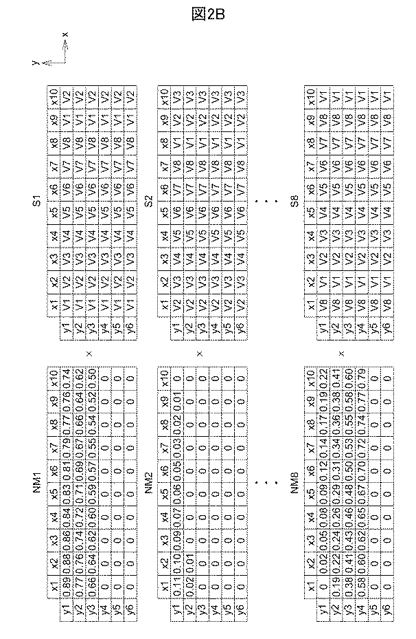
表1は、調整済みの第1の閲覧角度行列表S1’を示す。表1の調整済みの第1の閲覧角度行列表S1’を例として採用する。調整済みの第1の閲覧角度行列表S1’の座標(x1,y1)におけるピクセルV’の情報は、演算表NM1の座標(x1,y1)における重み情報と閲覧角度行列表S1の座標(x1,y1)における閲覧角度情報との積と、演算表NM2の座標(x1,y1)における重み情報と閲覧角度行列表S2の座標(x1,y1)における閲覧角度情報との積と、そこから最後の演算表NM8の座標(x1,y1)における重み情報と最後の閲覧角度行列表S8の座標(x1,y1)における閲覧角度情報との積までとの和に等しい。すなわち、ピクセルV1’=0.89×v1+0.11×v2+...+0×v8である。他の座標におけるピクセルの情報も、ピクセルV1’の情報を取得する方法と同じ方法に従って取得することができる。 Table 1 shows the adjusted first viewing angle matrix table S1 '. The adjusted first viewing angle matrix table S1 'of Table 1 is taken as an example. The information of the pixel V ′ at the coordinate (x1, y1) of the adjusted first viewing angle matrix table S1 ′ is the weight information at the coordinate (x1, y1) of the calculation table NM1 and the coordinate (x1) of the viewing angle matrix table S1. , Y1) and the product of the viewing angle information at the coordinates (x1, y1) of the calculation table NM2 and the viewing angle information at the coordinates (x1, y1) of the viewing angle matrix table S2, and the last Is equal to the sum of the weight information at the coordinates (x1, y1) in the calculation table NM8 and the product of the viewing angle information at the coordinates (x1, y1) in the last viewing angle matrix table S8. That is, pixel V1 '= 0.89 * v1 + 0.11 * v2 +. . . + 0 × v8. Information on pixels at other coordinates can also be obtained according to the same method as the method for obtaining information on the pixel V1 '.
表2は、本発明の別の実施形態による偶数のN閲覧角度行列の変換方法の概略図を示す。閲覧角度情報Jは変換されない閲覧角度情報を表し、閲覧角度情報J’は変換された閲覧角度情報を表す。閲覧角度数が偶数である場合、G番目の閲覧角度フレームのG列目内の閲覧角度情報は、第1の初期行列の(G+zN)列目に適用される。さらに、変換列は閲覧角度数の半分に1を足したものに対応し、続く閲覧角度情報は徐々に低減するように変換される。(N−H+2)番目の閲覧角度フレームの(N−H+2)列目内の閲覧角度情報は、第1の初期行列の(H+zN)列目に適用される。但し、Gは1〜(N/2)+1の自然数であり、Hは(N/2)+2〜Nの自然数であり、zは0よりも大きな自然数であるか、又は0に等しく、zの上限はフレームの解像度に関連付けられる。ここでは、閲覧角度情報列をサンプリングする方法は限定ではなく、閲覧角度情報は行、斜線、ジグザグ線、又はさらには不規則なポイントであってもサンプリングすることができる。中央列に近い閲覧角度の位置を、徐々に低減するように閲覧角度情報を変換する変換列として使用することにより、閲覧角度情報V8から閲覧角度情報V1への当初の大きな飛びを回避することができ、それにより、閲覧者は、大きな飛びを有する閲覧角度情報を見ることから生じる不快さを経験しない。 Table 2 shows a schematic diagram of an even N viewing angle matrix conversion method according to another embodiment of the present invention. The viewing angle information J represents viewing angle information that is not converted, and the viewing angle information J ′ represents converted viewing angle information. When the number of viewing angles is an even number, the viewing angle information in the Gth column of the Gth viewing angle frame is applied to the (G + zN) th column of the first initial matrix. Further, the conversion sequence corresponds to a half of the viewing angle number plus 1 and the subsequent viewing angle information is converted so as to gradually decrease. The viewing angle information in the (N−H + 2) th column of the (N−H + 2) th viewing angle frame is applied to the (H + zN) th column of the first initial matrix. Where G is a natural number from 1 to (N / 2) +1, H is a natural number from (N / 2) +2 to N, z is a natural number greater than or equal to 0, and z The upper limit is related to the resolution of the frame. Here, the method of sampling the viewing angle information sequence is not limited, and the viewing angle information can be sampled even if it is a line, a diagonal line, a zigzag line, or even an irregular point. By using the position of the viewing angle close to the center row as a conversion row for converting the viewing angle information so as to gradually decrease, the initial large jump from the viewing angle information V8 to the viewing angle information V1 can be avoided. Yes, so that the viewer does not experience the discomfort resulting from viewing viewing angle information with large jumps.
図3は、本発明の別の実施形態による演算表NM1〜NM8及び閲覧角度行列表J’1〜J’8の概略図を示す。演算表NM1〜NM8に記憶される重み情報は、第1の実施形態の演算表NM1〜NM8に記憶されるものと同じである。調整済み閲覧角度情報の計算は、閲覧角度行列表J’1〜J’8に記憶される閲覧角度情報を除き、第1の実施形態と同様である。図3の閲覧角度行列表J’1〜J’8は、図2Bの閲覧角度行列の対応する閲覧角度情報を、表2の変換された閲覧角度情報J’で置換することにより得られる。次に、処理装置は、各閲覧角度号列表J’1〜J’8の各閲覧角度情報と、対応する重み情報との積の和を計算し、調整された8つの閲覧角度情報ピクセル情報を出力する。 FIG. 3 shows a schematic diagram of operation tables NM1 to NM8 and viewing angle matrix tables J′1 to J′8 according to another embodiment of the present invention. The weight information stored in the calculation tables NM1 to NM8 is the same as that stored in the calculation tables NM1 to NM8 of the first embodiment. The adjustment of the adjusted viewing angle information is the same as that in the first embodiment except for the viewing angle information stored in the viewing angle matrix tables J′1 to J′8. The viewing angle matrix tables J′1 to J′8 in FIG. 3 are obtained by replacing the corresponding viewing angle information in the viewing angle matrix in FIG. 2B with the converted viewing angle information J ′ in Table 2. Next, the processing device calculates the sum of products of each viewing angle information of each viewing angle sequence table J′1 to J′8 and the corresponding weight information, and sets the adjusted eight viewing angle information pixel information. Output.
表3は、本発明の別の実施形態による奇数の閲覧角度行列の変換方法の概略図を示す。閲覧角度情報Kは変換されない閲覧角度情報を表し、閲覧角度情報K’は変換された閲覧角度情報を表す。閲覧角度数が奇数である場合、変換列は閲覧角度数の和の半分に1を足したものに対応する。G番目の閲覧角度フレームのG列目内の閲覧角度情報は、第1の初期行列の(G+zN)列目に適用される。さらに、(N−H+2)番目の閲覧角度フレームの(N−H+2)列目内の閲覧角度情報は、第1の初期行列の(H+zN)列目に適用される。但し、Gは1〜(N+1/2)の自然数であり、Hは(N+1/2)+1〜Nの自然数であり、zは0よりも大きな自然数であるか、又は0に等しく、zの上限はフレームの解像度に関連付けられる。ここでは、閲覧角度情報列をサンプリングする方法は限定ではなく、閲覧角度情報は行、斜線、ジグザグ線、又はさらには不規則なポイントであってもサンプリングすることができる。 Table 3 shows a schematic diagram of a method for converting an odd viewing angle matrix according to another embodiment of the present invention. The viewing angle information K represents viewing angle information that is not converted, and the viewing angle information K ′ represents converted viewing angle information. When the viewing angle number is an odd number, the conversion sequence corresponds to the sum of the viewing angle number plus one. The viewing angle information in the G column of the Gth viewing angle frame is applied to the (G + zN) column of the first initial matrix. Further, the viewing angle information in the (N−H + 2) th column of the (N−H + 2) th viewing angle frame is applied to the (H + zN) th column of the first initial matrix. However, G is a natural number of 1 to (N + 1/2), H is a natural number of (N + 1/2) +1 to N, z is a natural number greater than or equal to 0, and the upper limit of z Is associated with the frame resolution. Here, the method of sampling the viewing angle information sequence is not limited, and the viewing angle information can be sampled even if it is a line, a diagonal line, a zigzag line, or even an irregular point.
図4は、本発明の別の実施形態による演算表NM1〜NM7及び閲覧角度行列表K’1〜K’7の概略図を示す。演算表NM1〜NM7に記憶される重み情報は、第1の実施形態の演算表NM1〜NM7に記憶されるものと同じである。調整済み閲覧角度情報の計算は、閲覧角度行列表K’1〜K’7に記憶される閲覧角度情報を除き、第1の実施形態と同様である。図4の閲覧角度行列表K’1〜K’7は、図2Bの閲覧角度行列の対応する閲覧角度情報を、表3の変換された閲覧角度情報K’で置換することにより得られる。中央列に近い閲覧角度の位置を、徐々に低減するように閲覧角度情報を変換する変換列として使用することにより、閲覧角度情報V7から閲覧角度情報V1への当初の大きな飛びを回避することができ、それにより、閲覧者は、大きな飛びを有する閲覧角度情報を見ることから生じる不快さを経験しない。したがって、調整済み画像は、計算結果に従って表示ユニット106に出力され、表示ユニット106は正確な三次元画像を表示することができる。
FIG. 4 shows a schematic diagram of operation tables NM1 to NM7 and viewing angle matrix tables K′1 to K′7 according to another embodiment of the present invention. The weight information stored in the calculation tables NM1 to NM7 is the same as that stored in the calculation tables NM1 to NM7 of the first embodiment. The adjustment of the adjusted viewing angle information is the same as that in the first embodiment except for the viewing angle information stored in the viewing angle matrix tables K′1 to K′7. The viewing angle matrix tables K′1 to K′7 in FIG. 4 are obtained by replacing the corresponding viewing angle information in the viewing angle matrix in FIG. 2B with the converted viewing angle information K ′ in Table 3. By using the position of the viewing angle close to the central row as a conversion row for converting the viewing angle information so as to gradually decrease, the initial large jump from the viewing angle information V7 to the viewing angle information V1 can be avoided. Yes, so that the viewer does not experience the discomfort resulting from viewing viewing angle information with large jumps. Therefore, the adjusted image is output to the
第2の実施形態
図5Aは、本発明の別の実施形態による三次元画像表示調整システム10’の概略図を示す。図5Aを参照する。三次元画像表示システム10’は、2D/3D切り替え可能表示装置等の表示装置100’を備える。表示装置100’は、処理装置102、アクティブ化ユニット104’、及び表示ユニット106’を備える。処理装置102は、記憶ユニット1020、信号生成ユニット1022、計算ユニット1024、及び駆動ユニット1026を備えることができる。表示装置100’は表示装置100と同様であるため、同じ要素は同じ名称を保持し、同様のことに関してはここで繰り返さない。
Second Embodiment FIG. 5A shows a schematic diagram of a three-dimensional image
図5Bは、本発明の別の実施形態による三次元画像表示調整方法の概略図を示す。図5A及び図5Bを同時に参照する。表示装置100は、参照画像P1及び見当合わせ画像P2を含む調整パターンの表示に使用される、タッチ表示ユニット等の表示ユニット106’を有する。本実施形態では、アクティブ化ユニット104’は光学素子により実現することができる。光学素子は、レンチキュラーレンズ又は格子を有するカバー等である。カバーは、表示ユニット106’の表示エリアAAを覆い、表示ユニット106’の表示エリアAAの光出力路を変更することができる。一実施形態では、アクティブ化ユニット104’は、アクティブ化ユニット104’(光学素子等)がタッチ表示装置に接触する場合、表示装置100の三次元画像表示機能を自動的にアクティブ化する。
FIG. 5B shows a schematic diagram of a 3D image display adjustment method according to another embodiment of the present invention. Please refer to FIG. 5A and FIG. 5B simultaneously. The
本実施形態は、説明のために参照画像P1及び見当合わせ画像P2によっても例示される。見当合わせ画像P2により表される十字が、参照画像P1により表される中空の十字の中央内に配置されない場合、ユーザーは、タッチ表示ユニット106’が、見当合わせ画像P2を調整する調整コマンドを入力する調整ステップを実行することができる。その一方で、調整コマンドは、指でタッチ表示ユニット106’をスライドさせることにより、又はタッチ表示ユニット106’に接触する他の方法により入力され、本発明はそれに限定されない。
This embodiment is also exemplified by a reference image P1 and a registration image P2 for the sake of explanation. When the cross represented by the registration image P2 is not arranged in the center of the hollow cross represented by the reference image P1, the user inputs an adjustment command for adjusting the registration image P2 by the
次に、表示ユニット106’は、調整コマンドを処理装置102に出力することができる。処理装置102は、調整コマンドに従って計算結果を生成し、調整結果を取得する。特に、調整ステップが実行される都度入力される調整コマンドは、検討合わせ画像P2を特定の距離だけ特定の方向にシフトする等の調整メッセージに対応することができる。調整ステップを多数回実行した後、処理装置102は複数の調整メッセージを取得することができる。処理装置102は、調整メッセージをまとめて、調整結果を取得することができる。調整結果が正確であると判断される場合、計算ユニット1024は、調整結果に従って計算結果を生成し、計算結果に従って調整された画像を表示ユニット106’に出力することができる。計算ユニット1024により計算結果を生成する方法の詳細な手順は図2〜図4及び表1〜表3に開示されるが、ここで繰り返さない。
The
第3の実施形態
図6Aは、本発明の代替の実施形態による三次元画像表示調整システム20の概略図を示す。図6Aを参照すると、三次元画像表示調整システム20は、表示装置200及び通信装置220を備える。2D/3D切り替え可能表示装置等の表示装置200は、処理装置102、アクティブ化ユニット104、表示ユニット106、及び第1の通信ユニット208を備える。処理装置102は、記憶ユニット1020、信号生成ユニット1022、計算ユニット1024、及び駆動ユニット1026を備えることができる。表示装置200は表示装置100と同様であるため、同じ要素は同じ名称を保持し、同様のことに関してはここで繰り返さない。表示装置200は、第1の通信ユニット208を更に備えるという点で表示装置100と異なる。
Third Embodiment FIG. 6A shows a schematic diagram of a three-dimensional image
通信装置220は、カメラ、携帯電話、及び遠隔コントローラー等のネットワーク通信機能を有する任意の電子装置により実現することができ、又はBluetooth(登録商標)若しくはネットワーク通信機能を有する任意のヘッドセット若しくは眼鏡により実現することができる。通信装置220は、処理装置222、画像捕捉ユニット224、入力ユニット226、及び第2の通信ユニット228を備えることができる。処理装置222及び処理装置102は互いに同様であり、ユーザーはそれらの任意の1つを選ぶことができる。以下の実施形態では、表示装置200は処理装置102を備える。しかし、通信装置220が処理装置222を備える限り、通信装置220は、表示装置200の処理装置102を、処理装置102の機能を実行する処理装置222で置換することができる。
The
図6Bは、本発明の代替の実施形態による三次元画像表示調整方法の概略図を示す。図6A及び図6Bを同時に参照する。表示装置200は、調整パターン(すなわち、参照画像P1及び見当合わせ画像P2)の表示に使用される表示ユニット106を有する。本実施形態では、アクティブ化ユニット104は、三次元画像表示機能のアクティブ化に使用される。一実施形態では、アクティブ化ユニット104は開始ボタン等であり、ユーザーは開始ボタンに触れて、三次元画像表示機能をアクティブ化することができる。別の実施形態では、表示装置200に三次元画像表示機能をアクティブ化させるように命令するトリガー信号が、通信装置220の入力ユニット226を介して入力される。
FIG. 6B shows a schematic diagram of a 3D image display adjustment method according to an alternative embodiment of the present invention. Please refer to FIG. 6A and FIG. 6B simultaneously. The
本実施形態は、参照画像P1及び見当合わせ画像P2によっても例示される。通信装置220の入力ユニット226は、キーボード、押しボタン、ターンテーブル、ローラー、又は他の形態の入力インターフェース等であり、本発明はそれに限定されない。通信装置220の画像捕捉ユニット224は、表示ユニット106により表示されるフレームの情報を捕捉するのに使用されるカメラ等の電荷結合素子(CCD)であり、第2の通信ユニット226が、捕捉されたフレーム情報を第1の通信ユニット208に更に送信する。次に、処理装置102は、フレーム情報を調整パターンと比較し、調整コマンドに従って計算結果を生成して、調整結果を取得する。一実施形態では、通信装置220は、処理装置222を使用して、フレーム情報を調整パターンと比較し、調整結果を取得することができ、次に、第2の通信ユニット226を使用して、調整結果を第1の通信ユニット208に送信することができる。第1の通信ユニット208と第2の通信ユニット226との間での伝送は、無線ローカルエリアネットワーク(WLAN)のWi−Fi、Bluetooth、赤外線(IR)光又はデジタルリビングネットワークアライアンス(DLNA)により実施することができ、本発明はそれに限定されない。
This embodiment is also exemplified by the reference image P1 and the registration image P2. The
見当合わせ画像P2により表される十字が、参照画像P1により表される中空の十字の中央内に配置されない場合、三次元画像が正確に形成されないと判断される。その間、処理装置102は、見当合わせ画像P2が、参照画像P1により表される中空の十字内に配置されるように調整コマンドが表示ユニット106に提供される調整ステップを実行することができる。処理装置102は、調整コマンドに従って計算結果を生成し、調整結果を取得する。一実施形態では、処理装置222は処理装置1022に取って代わり、調整ステップを実行し、第2の通信ユニット228は、調整結果を第1の通信ユニット208に送信する。次に、第1の通信ユニット208は、調整結果を表示ユニット106に出力する。
If the cross represented by the registration image P2 is not arranged in the center of the hollow cross represented by the reference image P1, it is determined that the three-dimensional image is not accurately formed. Meanwhile, the
次に、処理装置102は、調整結果が正確であるか否かの判断に続く。正確である場合、通信ユニット1024は、調整結果に従って計算結果を生成し、計算結果に従って調整された画像を表示ユニット106に出力する。調整結果が不正確である場合、調整結果が正確になるまで調整ステップが繰り返される。計算ユニット1024により計算結果を生成する方法の詳細な手順は、図2〜図4及び表1〜表3に開示され、同様のことに関してはここで繰り返さない。
Next, the
図7は、本発明の一実施形態による三次元画像表示調整方法のフローチャートを示す。図7を参照する。まず、方法がステップS1において開始され、三次元画像表示機能がアクティブ化される。次に、方法はステップS2に進み、調整パターン(三次元)が表示される。次に、方法はステップS3に進み、調整ステップが実行されて、調整結果が取得される。次に、方法はステップS4に進み、調整結果が正確であるか否かが判断される。本ステップにおいて、ユーザーは、観測された画像に従って調整結果が正確であるか否かを判断することができ、又は判断を三次元画像ディスプレイの処理装置に任せることができる。調整結果が正確であると判断される場合、方法はステップS5に進む。ステップS5において、処理装置は、調整結果に従って計算結果を取得する。次に、方法はステップS6に進み、計算結果が、三次元画像を表示する表示ユニットに出力される。調整結果が不正確であると判断される場合、ステップS2〜S4は、調整結果が正確になるまで繰り返される。 FIG. 7 shows a flowchart of a 3D image display adjustment method according to an embodiment of the present invention. Please refer to FIG. First, the method is started in step S1, and the 3D image display function is activated. Next, the method proceeds to step S2 where an adjustment pattern (three-dimensional) is displayed. Next, the method proceeds to step S3, where the adjustment step is executed and the adjustment result is obtained. Next, the method proceeds to step S4 where it is determined whether the adjustment result is accurate. In this step, the user can determine whether the adjustment result is accurate according to the observed image, or can leave the determination to the processing device of the 3D image display. If it is determined that the adjustment result is correct, the method proceeds to step S5. In step S5, the processing device acquires a calculation result according to the adjustment result. Next, the method proceeds to step S6, and the calculation result is output to the display unit that displays the three-dimensional image. If it is determined that the adjustment result is inaccurate, steps S2 to S4 are repeated until the adjustment result is accurate.
三次元画像表示システム及びその調整方法が、本発明の上記実施形態において開示される。計算結果は、表示装置が計算結果に従って正確な三次元画像を出力することができ、ユーザーが、三次元画像を見る際に画像の飛びを不愉快に感じないように、調整ステップを実行することにより取得される調整結果に従って生成される。 A three-dimensional image display system and its adjustment method are disclosed in the above embodiment of the present invention. The calculation result is obtained by executing an adjustment step so that the display device can output an accurate three-dimensional image according to the calculation result and the user does not feel uncomfortable when the three-dimensional image is viewed. Generated according to the obtained adjustment result.
本発明を例としてかつ好ましい実施形態に関して説明したが、本発明はそれに限定されないことを理解されたい。反対に、様々な変更並びに同様の配置及び手順を包含することが意図されており、したがって、添付の特許請求の範囲の範囲は全てのこのような変更並びに同様の配置及び手順を網羅するように最も広く解釈されるべきである。 While the invention has been described by way of example and in terms of a preferred embodiment, it is to be understood that the invention is not limited thereto. On the contrary, it is intended to encompass various modifications and similar arrangements and procedures, and thus the scope of the appended claims is intended to cover all such modifications and similar arrangements and procedures. It should be interpreted most widely.
Claims (20)
調整パターンを表示装置に表示するステップと、
前記調整パターンに従って調整結果を取得するために調整ステップを実行するステップと、
前記調整結果に従って計算結果を生成するステップと、
前記計算結果に従って調整された三次元画像を前記表示装置に出力するステップと、
を含む、調整方法。 An adjustment method,
Displaying the adjustment pattern on the display device;
Performing an adjustment step to obtain an adjustment result according to the adjustment pattern;
Generating a calculation result according to the adjustment result;
Outputting a three-dimensional image adjusted according to the calculation result to the display device;
Including the adjustment method.
画像捕捉ユニットによりフレーム情報を取得するステップと、
前記調整結果を取得するために処理装置により前記フレーム情報を前記調整パターンと比較するステップと、
を更に含む、請求項1に記載の調整方法。 The adjusting step includes
Obtaining frame information by an image capture unit;
Comparing the frame information with the adjustment pattern by a processing device to obtain the adjustment result;
The adjustment method according to claim 1, further comprising:
前記処理装置により調整メッセージを受信するステップであって、前記調整メッセージには、前記調整パターンと前記フレーム情報との比較結果が関連付けられる、ステップと、
前記調整メッセージに従って前記調整結果を計算するステップと、
を更に含む、請求項2に記載の調整方法。 The adjusting step includes
Receiving an adjustment message by the processing device, wherein the adjustment message is associated with a comparison result between the adjustment pattern and the frame information;
Calculating the adjustment result according to the adjustment message;
The adjustment method according to claim 2, further comprising:
画像のN個の閲覧角度情報の配置を通して形成されるN個の閲覧角度行列表を提供するステップであって、Nは2よりも大きな自然数である、ステップと、
前記N個の閲覧角度行列表にそれぞれ対応するN個の演算表を提供するステップであって、前記各演算表は、前記調整結果に関連付けられた複数の重み情報を含む、ステップと、
調整されたN個の閲覧角度フレーム情報を取得するために前記各閲覧角度情報と前記対応する重み情報との積の和を計算するステップと、
を更に含む、請求項1に記載の調整方法。 The step of generating the calculation result includes:
Providing N viewing angle matrix tables formed through an arrangement of N viewing angle information of an image, wherein N is a natural number greater than 2, and
Providing N calculation tables respectively corresponding to the N viewing angle matrix tables, each calculation table including a plurality of weight information associated with the adjustment results;
Calculating a sum of products of each viewing angle information and the corresponding weight information to obtain adjusted N viewing angle frame information;
The adjustment method according to claim 1, further comprising:
前記画像のN個の閲覧角度フレームを提供するステップであって、前記各閲覧角度フレームは、M個のピクセル情報に対応するM個の位置を含む、ステップと、
N個の初期行列を提供するステップであって、前記各初期行列はM個の位置を含む、ステップと、
前記閲覧角度行列表を取得するために前記初期行列内の対応する位置に前記閲覧角度フレームの前記閲覧角度情報を記入するステップと、
を含む、請求項5に記載の調整方法。 Providing the N viewing angle matrix tables includes:
Providing N viewing angle frames of the image, wherein each viewing angle frame includes M positions corresponding to M pixel information;
Providing N initial matrices, each initial matrix including M positions;
Writing the viewing angle information of the viewing angle frame at a corresponding position in the initial matrix to obtain the viewing angle matrix table;
The adjustment method according to claim 5, comprising:
アクティブ化ユニットの光学素子がタッチ表示ユニットに接触しているか否かを前記処理装置により検出するステップと、
前記三次元画像表示機能を自動的にアクティブ化するために前記処理装置によりトリガー信号を出力するステップと、
を含む、請求項7に記載の調整方法。 Activating the 3D image display function of the display device,
Detecting by the processing device whether the optical element of the activation unit is in contact with the touch display unit;
Outputting a trigger signal by the processing device to automatically activate the 3D image display function;
The adjustment method according to claim 7, comprising:
前記表示装置の画像捕捉ユニットにより調整コマンド及び初期情報を取得するステップと、
前記調整コマンド及び前記初期情報に従って前記調整パターンを取得するステップと、
を更に含む、請求項1に記載の調整方法。 The adjusting step includes
Obtaining an adjustment command and initial information by an image capture unit of the display device;
Obtaining the adjustment pattern according to the adjustment command and the initial information;
The adjustment method according to claim 1, further comprising:
正確である場合、前記調整された三次元画像は前記表示装置に出力され、
正確でない場合、前記調整するステップが繰り返される、請求項1に記載の調整方法。 Further comprising determining whether the adjustment result is accurate;
If correct, the adjusted 3D image is output to the display device;
The method of claim 1, wherein if not accurate, the step of adjusting is repeated.
三次元画像及び調整パターンを表示する、表示ユニットを有する表示装置と、
前記調整パターンに従って調整ステップを実行して調整結果を取得し、該調整結果に従って計算結果を生成し、該計算結果に従って調整された三次元画像を前記表示ユニットに出力する、前記表示ユニットに電気的に接続された処理装置と、
を備える、三次元表示システム。 A three-dimensional display system,
A display device having a display unit for displaying a three-dimensional image and an adjustment pattern;
An adjustment step is executed according to the adjustment pattern to obtain an adjustment result, a calculation result is generated according to the adjustment result, and a three-dimensional image adjusted according to the calculation result is output to the display unit. A processing device connected to the
A three-dimensional display system.
前記表示ユニットに駆動信号を提供する駆動ユニットと、
画像のN個の閲覧角度情報の配置の繰り返しを通して形成されるN個の閲覧角度行列表を記憶する記憶ユニットであって、Nは2よりも大きな自然数である、記憶ユニットと、
N個の閲覧角度と同じ数の演算表を生成する信号生成ユニットと、
前記調整結果に従ってN個の演算表を生成し、各閲覧角度情報と対応する重み情報との積の和を計算して、調整されたN個の閲覧角度行列ピクセル情報を出力する計算ユニットであって、前記演算表はそれぞれ、前記閲覧角度行列表に対応し、前記各演算表は、前記調整結果に関連付けられた複数の重み情報を有する、計算ユニットと、
を更に備える、請求項11に記載の三次元表示システム。 The processor is
A drive unit for providing a drive signal to the display unit;
A storage unit for storing N viewing angle matrix tables formed through repetition of arrangement of N viewing angle information of an image, wherein N is a natural number greater than 2,
A signal generation unit that generates the same number of operation tables as N viewing angles;
A calculation unit that generates N calculation tables according to the adjustment result, calculates a sum of products of each viewing angle information and corresponding weight information, and outputs adjusted N viewing angle matrix pixel information. Each of the calculation tables corresponds to the viewing angle matrix table, and each calculation table includes a plurality of weight information associated with the adjustment results;
The three-dimensional display system according to claim 11, further comprising:
Applications Claiming Priority (2)
| Application Number | Priority Date | Filing Date | Title |
|---|---|---|---|
| TW101143276 | 2012-11-20 | ||
| TW101143276A TWI524736B (en) | 2012-11-20 | 2012-11-20 | Three dimensional image display system and adjusting method thereof |
Publications (1)
| Publication Number | Publication Date |
|---|---|
| JP2014103670A true JP2014103670A (en) | 2014-06-05 |
Family
ID=49585270
Family Applications (1)
| Application Number | Title | Priority Date | Filing Date |
|---|---|---|---|
| JP2013238670A Pending JP2014103670A (en) | 2012-11-20 | 2013-11-19 | Three dimensional image display system and adjusting method thereof |
Country Status (4)
| Country | Link |
|---|---|
| US (1) | US20140139517A1 (en) |
| EP (1) | EP2733949A3 (en) |
| JP (1) | JP2014103670A (en) |
| TW (1) | TWI524736B (en) |
Cited By (2)
| Publication number | Priority date | Publication date | Assignee | Title |
|---|---|---|---|---|
| JP2019068430A (en) * | 2014-06-18 | 2019-04-25 | サムスン エレクトロニクス カンパニー リミテッド | Naked eye 3D display device and setting method |
| US11428951B2 (en) | 2014-06-18 | 2022-08-30 | Samsung Electronics Co., Ltd. | Glasses-free 3D display mobile device, setting method of the same, and using method of the same |
Families Citing this family (2)
| Publication number | Priority date | Publication date | Assignee | Title |
|---|---|---|---|---|
| TWI552729B (en) * | 2014-06-13 | 2016-10-11 | Cheng-Xin She | A system and method for image correction design of jaw jaw surgery |
| KR102370062B1 (en) | 2014-11-24 | 2022-03-04 | 삼성전자주식회사 | Method of determining calibration parameter for 3d display device and 3d display device thereof |
Family Cites Families (17)
| Publication number | Priority date | Publication date | Assignee | Title |
|---|---|---|---|---|
| US6177952B1 (en) * | 1993-09-17 | 2001-01-23 | Olympic Optical Co., Ltd. | Imaging apparatus, image display apparatus and image recording and/or reproducing apparatus |
| GB9715397D0 (en) * | 1997-07-23 | 1997-09-24 | Philips Electronics Nv | Lenticular screen adaptor |
| JP2003018619A (en) * | 2001-07-03 | 2003-01-17 | Olympus Optical Co Ltd | Three-dimensional image evaluation apparatus and display using the same |
| AU2003226187A1 (en) * | 2002-03-28 | 2003-10-13 | Nokia Corporation | Detecting misalignment and distortion in near-eye displays |
| EP1728116B1 (en) * | 2004-03-12 | 2012-09-19 | Koninklijke Philips Electronics N.V. | Multiview display device |
| KR100711199B1 (en) * | 2005-04-29 | 2007-04-24 | 한국과학기술원 | Incorrect Alignment Error Detection and Image Distortion Compensation Method |
| US8010299B2 (en) * | 2005-11-16 | 2011-08-30 | Chemometec A/S | Determination of chemical or physical properties of sample or component of a sample |
| IL174170A (en) * | 2006-03-08 | 2015-02-26 | Abraham Aharoni | Device and method for binocular alignment |
| US7538876B2 (en) * | 2006-06-12 | 2009-05-26 | The Boeing Company | Efficient and accurate alignment of stereoscopic displays |
| US8717392B2 (en) * | 2009-06-02 | 2014-05-06 | Nokia Corporation | Apparatus for enabling users to view images, methods and computer readable storage mediums |
| US20110157329A1 (en) * | 2009-12-28 | 2011-06-30 | Acer Incorporated | Method for switching to display three-dimensional images and digital display system |
| US8826184B2 (en) * | 2010-04-05 | 2014-09-02 | Lg Electronics Inc. | Mobile terminal and image display controlling method thereof |
| JP5462094B2 (en) * | 2010-07-07 | 2014-04-02 | 株式会社ソニー・コンピュータエンタテインメント | Image processing apparatus and image processing method |
| US8831677B2 (en) * | 2010-11-17 | 2014-09-09 | Antony-Euclid C. Villa-Real | Customer-controlled instant-response anti-fraud/anti-identity theft devices (with true-personal identity verification), method and systems for secured global applications in personal/business e-banking, e-commerce, e-medical/health insurance checker, e-education/research/invention, e-disaster advisor, e-immigration, e-airport/aircraft security, e-military/e-law enforcement, with or without NFC component and system, with cellular/satellite phone/internet/multi-media functions |
| RU2012104001A (en) * | 2010-11-22 | 2014-12-27 | Кабусики Кайся Тосиба | DEVICE AND METHOD FOR DISPLAYING STEREOSCOPIC IMAGES |
| TW201306556A (en) * | 2011-07-20 | 2013-02-01 | Delta Electronics Inc | Image control device and image display system comprising the same |
| TWI504933B (en) * | 2012-06-13 | 2015-10-21 | Innolux Corp | 2d/3d switchable display device and method for manufacturing the same |
-
2012
- 2012-11-20 TW TW101143276A patent/TWI524736B/en not_active IP Right Cessation
-
2013
- 2013-10-28 US US14/064,356 patent/US20140139517A1/en not_active Abandoned
- 2013-11-05 EP EP13191666.0A patent/EP2733949A3/en not_active Withdrawn
- 2013-11-19 JP JP2013238670A patent/JP2014103670A/en active Pending
Cited By (2)
| Publication number | Priority date | Publication date | Assignee | Title |
|---|---|---|---|---|
| JP2019068430A (en) * | 2014-06-18 | 2019-04-25 | サムスン エレクトロニクス カンパニー リミテッド | Naked eye 3D display device and setting method |
| US11428951B2 (en) | 2014-06-18 | 2022-08-30 | Samsung Electronics Co., Ltd. | Glasses-free 3D display mobile device, setting method of the same, and using method of the same |
Also Published As
| Publication number | Publication date |
|---|---|
| TW201421976A (en) | 2014-06-01 |
| EP2733949A3 (en) | 2015-01-21 |
| TWI524736B (en) | 2016-03-01 |
| US20140139517A1 (en) | 2014-05-22 |
| EP2733949A2 (en) | 2014-05-21 |
Similar Documents
| Publication | Publication Date | Title |
|---|---|---|
| US10855976B2 (en) | Display device and displaying method for glass-free stereoscopic image | |
| CN102918579B (en) | Image capture and display device and method | |
| CN102006491B (en) | Three dimensional display device and method of controlling parallax barrier | |
| WO2018058914A1 (en) | Naked-eye 3d display device and display method thereof | |
| US20120200680A1 (en) | Display device and method for providing 3D image of the display device | |
| CN103392342B (en) | Method and device for adjusting viewing zone, device capable of realizing stereoscopic display of video signals | |
| JP5833667B2 (en) | Method and apparatus for providing monovision in a multi-view system | |
| KR20070005616A (en) | 3-D Acquisition and Visualization System for Personal Electronic Devices | |
| WO2011036827A1 (en) | 3d image display device and 3d image display method | |
| JP2015528234A (en) | Display device imitating holographic 3D scene and visual display method | |
| KR101960897B1 (en) | Stereoscopic image display device and displaying method thereof | |
| WO2015180402A1 (en) | Display control method, apparatus and system | |
| JP2015149718A (en) | Display apparatus and controlling method thereof | |
| TW201407195A (en) | Auto-stereoscopic display having multi-user tracing function and method thereof | |
| JP2014103670A (en) | Three dimensional image display system and adjusting method thereof | |
| TWI515457B (en) | Multi-view three dimensional display system and control method thereof | |
| JP2011081269A (en) | Image display device and image display method | |
| KR101888082B1 (en) | Image display apparatus, and method for operating the same | |
| KR20120018864A (en) | Method for processing image of multivision display system outputting 3 dimensional contents and multivision display system enabling of the method | |
| CN103841392B (en) | 3 D image display system and bearing calibration thereof | |
| JP2015037282A (en) | Image processing device, image processing method, and program | |
| Minami et al. | Portrait and landscape mode convertible stereoscopic display using parallax barrier | |
| JP2012083573A (en) | Stereoscopic video processor and method for controlling the same | |
| KR101398804B1 (en) | the eye position calculating method of the stereoscopy displaying device which consists of the pair-eye type eye position calculator, the fan-shape modified lenticular and the liquid crystal type barrier. | |
| US8928586B2 (en) | Stereoscopic display device |