JP2014100016A - Stator - Google Patents
Stator Download PDFInfo
- Publication number
- JP2014100016A JP2014100016A JP2012251018A JP2012251018A JP2014100016A JP 2014100016 A JP2014100016 A JP 2014100016A JP 2012251018 A JP2012251018 A JP 2012251018A JP 2012251018 A JP2012251018 A JP 2012251018A JP 2014100016 A JP2014100016 A JP 2014100016A
- Authority
- JP
- Japan
- Prior art keywords
- coil
- stator
- core back
- teeth
- core
- Prior art date
- Legal status (The legal status is an assumption and is not a legal conclusion. Google has not performed a legal analysis and makes no representation as to the accuracy of the status listed.)
- Granted
Links
Images


Abstract
Description
この発明は、コイルがティース部毎に挿入された各分割固定子ユニットが周方向に沿って配列された固定子に関する。 The present invention relates to a stator in which each divided stator unit in which a coil is inserted for each tooth portion is arranged along a circumferential direction.
従来、固定爪をティース部の頂部側からティース部の側面であるコイルエンド面とコイルエンド部との間に挿入し、ティース部のコイルエンド面に係止することで、ティース部の頂部側から留め具のコイル上面押圧枠をコイル側に押圧して、コイルをティース部に固定した分割固定子ユニットが知られている(例えば、特許文献1参照)。 Conventionally, a fixed claw is inserted between the coil end surface, which is the side surface of the tooth portion, from the top side of the tooth portion and locked to the coil end surface of the tooth portion, so that A split stator unit is known in which a coil upper surface pressing frame of a fastener is pressed to the coil side and the coil is fixed to a tooth portion (see, for example, Patent Document 1).
しかしながら、上記構成の分割固定子ユニットでは、コイルと面接触したトラック形状の上面押圧枠は、コイルを均等に押圧するのではなく、固定爪が挿入されるコイルエンド部と比較して、コイルエンド部間のコイルの中間部では押圧力が小さい。
従って、コイルは、その中間部が径内側方向に突出してしまい、固定子の内側に配置された回転子と接触するおそれがあるという問題点があった。
また、コイルの中間部がコアバック部と離間してしまい、コイルの放熱性が低下するという問題点もあった。
However, in the divided stator unit configured as described above, the track-shaped upper surface pressing frame that is in surface contact with the coil does not press the coil evenly, but compared with the coil end portion into which the fixed claw is inserted. The pressing force is small in the middle part of the coil between the parts.
Therefore, the coil has a problem in that the intermediate portion protrudes in the radially inward direction and may come into contact with the rotor disposed inside the stator.
In addition, there is a problem in that the intermediate portion of the coil is separated from the core back portion and the heat dissipation of the coil is lowered.
この発明は、かかる問題点を解決することを課題とするものであって、コイルの中間部を自身の弾性力によりコアバック部の内周面に押圧させることで、コイルの回転子との接触を防止でき、またコイルの放熱性が向上した固定子を得ることを目的とする。 An object of the present invention is to solve such problems, and by pressing the intermediate part of the coil against the inner peripheral surface of the core back part by its own elastic force, the coil contacts with the rotor. An object of the present invention is to obtain a stator with improved coil heat dissipation.
この発明に係る固定子は、コイルがティース部毎に挿入された各分割固定子ユニットが周方向に沿って連結された固定子であって、
各前記分割固定子ユニットは、コアバック部と、このコアバック部の中間部から径方向の内側に先端部が延びた前記ティース部とから構成されたコアブロック部と、
前記ティース部の軸線方向の両端面にそれぞれ固定部を介してベースが固定されているとともに、ベースの径方向の両側から軸線方向に先端部が延びた一対の鍔部を有するインシュレータと、
それぞれの前記インシュレータの各一対の前記鍔部間に軸線方向の両側に形成されたコイルエンド部がそれぞれ装着された前記コイルと、を備え、
前記コイルは、塑性変形により中間部が前記コアバック部側に突出してコイルの弾性力により前記コアバック部の内周面を押圧している。
The stator according to the present invention is a stator in which each divided stator unit in which a coil is inserted for each tooth portion is connected along a circumferential direction,
Each of the divided stator units has a core block portion including a core back portion and the teeth portion having a tip portion extending radially inward from an intermediate portion of the core back portion;
Insulators having a pair of flanges with distal ends extending in the axial direction from both radial sides of the base, with bases fixed to both end surfaces of the teeth part in the axial direction, respectively.
A coil end portion formed on each side of the axial direction between each pair of the flange portions of each of the insulators;
As for the said coil, the intermediate part protrudes to the said core back part side by plastic deformation, and is pressing the inner peripheral surface of the said core back part with the elastic force of a coil.
この発明に係る固定子によれば、コイルは、塑性変形により中間部がコアバック部側に突出してコイルの弾性力によりコアバック部の内周面を押圧しているので、回転子との接触を防止でき、また放熱性が向上する。 According to the stator according to the present invention, the coil protrudes toward the core back portion due to plastic deformation and presses the inner peripheral surface of the core back portion due to the elastic force of the coil. In addition, heat dissipation is improved.
以下、この発明の各実施の形態について図に基づいて説明するが、各図において、同一、または相当部材、部位については同一符号を付して説明する。
実施の形態1.
図1はこの発明の実施の形態1の固定子を示す全体斜視図である。
この固定子は、12個の分割固定子ユニット3を周方向に沿って組み合わせ、アウターリング15を嵌め込んで一体化されている。この固定子の中心軸線上には、回転子(図示せず)が設けられている。
この固定子は、ハイブリッド車等に搭載される駆動用モータの固定子である。
Hereinafter, embodiments of the present invention will be described with reference to the drawings. In the drawings, the same or equivalent members and parts will be described with the same reference numerals.
Embodiment 1 FIG.
1 is an overall perspective view showing a stator according to Embodiment 1 of the present invention.
This stator is integrated by combining twelve divided
This stator is a stator of a drive motor mounted on a hybrid vehicle or the like.
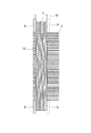
図2は図1の分割固定子ユニット3の全体斜視図、図3は図2の分割固定子ユニット3の分解斜視図、図4は図2の分割固定子ユニット3の側面図である。
各分割固定子ユニット3は、コアバック部11及びこのコアバック部11の中間部から径方向の内側に先端部が延びたティース部12から構成されたコアブロック部4と、ティース部12の軸線方向の両端面にそれぞれ固定部を介して固定された樹脂製のインシュレータ6と、ティース部12に装着されたコイル5と、を備えている。
インシュレータ6は、ベース7と、ベース7の径方向の両側から軸線方向に先端部が延びた一対の鍔部8と、を有している。インシュレータ6のベース7には、突起部9が形成されている。この突起部9は、ティース部12の両端面に形成された穴部14に嵌入されて、インシュレータ6は、コアブロック部4のティース部12に固定される。
インシュレータ6の各一対の鍔部8間には、コイル5のコイルエンド部13が収まっている。
2 is an overall perspective view of the
Each of the divided
The
A
コアブロック部4は、電磁鋼板をプレス等で積層して形成されており、一部がカシメ加工されることで一つの塊になっている。
ティース部12は、周方向の両面がそれぞれ平面形状であって、軸線に対して垂直方向に切断したときの形状は、台形形状である。
The
The
コイル5は、平角導体16がエッジワイズ曲げ加工で巻回形成されたものである。この平角導体16は、銅製の平角材の外周に絶縁皮膜が形成されている。絶縁皮膜はエナメルやアミドイミド等が用いられる。
ハイブリッド車等に搭載される駆動用モータは、エンジンルームに搭載されるので、小型で高出力なモータが要求される。
そして、この実施の形態では、固定子のコイル5の占積率を高めるために、丸線でコイルを形成するのではなく、平角導体16を巻回して形成されたコイル5が用いられている。
また、このコイル5は、中間部の折曲部10でV字状に塑性変形されている。
そして、コイル5が、各一対の鍔部8間にコイルエンド部13が収まってティース部12に挿入されたときには、図4に示すように、中央部がコアバック部11側に突出したコイル5の弾性力によりコアバック部11の内周面を押圧している。
The
A drive motor mounted in a hybrid vehicle or the like is mounted in an engine room, and thus a small and high-output motor is required.
In this embodiment, in order to increase the space factor of the
The
When the
上記構成の分割固定子ユニット3では、予め平角導体16を巻回してコイル5を形成し、このコイル5の両コイルエンド部13にそれぞれインシュレータ6を装着する。
この後、このコイル5をティース部12の先端部側から挿入し、インシュレータ6の突起部9をコイルエンド部13の穴部14に嵌入することで、コイル5のティース部12への装着が終了する。
なお、コイル5の挿入の際には、コイル5は、軸線方向(一対のコイルエンド部13が離れる方向)に塑性変形するので、突起部9がコイル5の挿入の邪魔になるようなことはない。
この後、コイルエンド部13に向けてワニスを滴下し、コイル5の平角導体16間にワニスを含浸させる。この際、コイル5は、中間部の折曲部10でV字状に塑性変形しており、コアバック部11の両端面側には隙間があるので、ワニスはコイル5の中間部に円滑に浸透する。
ワニスが固化した後、各分割固定子ユニット3を周方向に沿って円環状に配列した後、最後に外側にアウターリング15を嵌め込み、各分割固定子ユニット3が一体化された固定子が出来上がる。
In the
Thereafter, the
When the
Thereafter, varnish is dropped toward the
After the varnish has solidified, the divided
この実施の形態による固定子によれば、コイル5は、塑性変形により中間部がコアバック部11側に突出してコイル5の弾性力によりコアバック部11の内周面を押圧しているので、回転子との接触を防止でき、またコイル5の放熱性が向上する。
According to the stator according to this embodiment, the
また、ティース部12は、周方向の両面がそれぞれ平面形状であり、ティース部12の先端部が周方向に突出していないので、隣接したティース部12間のスロットは、開放スロットであり、予め平角導体16を巻回してコイル5を形成し、このコイル5をティース部12の先端部側から装着することができる。
従って、先端部に周方向に突出した鍔部を有するティース部であって、このティース部に平角導体を巻回してコイルを装着するものと比較して、分割固定子ユニット3の製造が簡単になる。
In addition, since the
Therefore, it is easier to manufacture the
また、固定部は、ベース7に形成された突起部9と、ティース部12に形成され突起部9が嵌入される穴部14とから構成されているので、ティース部12にインシュレータ6を簡単、確実に固定することができる。
Moreover, since the fixing part is composed of the protruding part 9 formed on the base 7 and the hole part 14 formed in the
また、コイル5は、平角導体16をエッジワイズ曲げ加工で巻回して形成されているので、コイル5は、高い占積率が確保され、小型で高出力なモータが得られる。
Further, since the
実施の形態2.
図5はこの発明の実施の形態2のコイル5の側面図である。
この実施の形態では、コイル5は、曲率半径Rが大きな値になるように塑性変形されている。
他の構成は、実施の形態1の分割固定子ユニット3と同じである。
この実施の形態では、コイル5は、曲率半径Rが大きな値になるように塑性変形されており、実施の形態1のものと比較して、塑性変形により中間部がコアバック部11側に突出してコイル5の弾性力によりコアバック部11の内周面を押圧する面積が増大し、それだけコイル5の放熱性が高いという効果がある。
Embodiment 2. FIG.
FIG. 5 is a side view of the
In this embodiment, the
Other configurations are the same as those of the
In this embodiment, the
なお、上記各実施の形態では、インシュレータ6に突起部9を形成し、コイル5の両端面に穴部14を形成して固定部を構成したが、インシュレータ6側に穴部を形成し、ティース部12側にこの穴部に嵌入する突起部を形成して固定部を構成してもよい。
また、アウターリング15を用いて複数の分割固定子ユニット3を円環状に一体化したが、隣接した分割固定子ユニット3同士を溶接により接続して一体化してもよい。
また、上記各実施の形態では、ハイブリッド車等に搭載される駆動用モータに用いられる固定子について説明したが、この発明は、他の用途のモータ固定子であってよく、また発電機の固定子にも適用できる。
In each of the above embodiments, the protrusions 9 are formed on the
Moreover, although the some division |
In each of the above embodiments, a stator used for a drive motor mounted on a hybrid vehicle or the like has been described. However, the present invention may be a motor stator for other uses, and a generator may be fixed. It can also be applied to children.
1 モータケース、2 ステータ、3 分割固定子ユニット、4 コアブロック部、5 コイル、6 インシュレータ、7 ベース、8 鍔部、9 突起部、10 折曲部、11 コアバック部、12 ティース部、13 コイルエンド部、14 穴部、15 アウターリング、16 平角導体。 DESCRIPTION OF SYMBOLS 1 Motor case, 2 stator, 3 division | segmentation stator unit, 4 core block part, 5 coil, 6 insulator, 7 base, 8 collar part, 9 protrusion part, 10 bending part, 11 core back part, 12 teeth part, 13 Coil end, 14 holes, 15 outer ring, 16 flat conductor.
Claims (4)
各前記分割固定子ユニットは、コアバック部と、このコアバック部の中間部から径方向の内側に先端部が延びた前記ティース部とから構成されたコアブロック部と、
前記ティース部の軸線方向の両端面にそれぞれ固定部を介してベースが固定されているとともに、ベースの径方向の両側から軸線方向に先端部が延びた一対の鍔部を有するインシュレータと、
それぞれの前記インシュレータの各一対の前記鍔部間に軸線方向の両側に形成されたコイルエンド部がそれぞれ装着された前記コイルと、を備え、
前記コイルは、塑性変形により中間部が前記コアバック部側に突出してコイルの弾性力により前記コアバック部の内周面を押圧している固定子。 Each divided stator unit in which a coil is inserted for each tooth part is a stator arranged along the circumferential direction,
Each of the divided stator units has a core block portion including a core back portion and the teeth portion having a tip portion extending radially inward from an intermediate portion of the core back portion;
Insulators having a pair of flanges with distal ends extending in the axial direction from both radial sides of the base, with bases fixed to both end surfaces of the teeth part in the axial direction, respectively.
A coil end portion formed on each side of the axial direction between each pair of the flange portions of each of the insulators;
The coil is a stator in which an intermediate portion protrudes toward the core back portion by plastic deformation and presses an inner peripheral surface of the core back portion by an elastic force of the coil.
Priority Applications (2)
| Application Number | Priority Date | Filing Date | Title |
|---|---|---|---|
| JP2012251018A JP5474166B1 (en) | 2012-11-15 | 2012-11-15 | stator |
| CN201310202324.9A CN103825377B (en) | 2012-11-15 | 2013-05-27 | Stator |
Applications Claiming Priority (1)
| Application Number | Priority Date | Filing Date | Title |
|---|---|---|---|
| JP2012251018A JP5474166B1 (en) | 2012-11-15 | 2012-11-15 | stator |
Publications (2)
| Publication Number | Publication Date |
|---|---|
| JP5474166B1 JP5474166B1 (en) | 2014-04-16 |
| JP2014100016A true JP2014100016A (en) | 2014-05-29 |
Family
ID=50749811
Family Applications (1)
| Application Number | Title | Priority Date | Filing Date |
|---|---|---|---|
| JP2012251018A Active JP5474166B1 (en) | 2012-11-15 | 2012-11-15 | stator |
Country Status (2)
| Country | Link |
|---|---|
| JP (1) | JP5474166B1 (en) |
| CN (1) | CN103825377B (en) |
Cited By (4)
| Publication number | Priority date | Publication date | Assignee | Title |
|---|---|---|---|---|
| JP2017139838A (en) * | 2016-02-01 | 2017-08-10 | 三菱電機株式会社 | Stator and rotary electric machine including the same |
| WO2018131205A1 (en) * | 2017-01-11 | 2018-07-19 | 三菱電機株式会社 | Rotating electric machine stator and rotating electric machine stator manufacturing method |
| WO2022172593A1 (en) * | 2021-02-15 | 2022-08-18 | パナソニックIpマネジメント株式会社 | Stator and brushless motor |
| JP2022550460A (en) * | 2019-10-03 | 2022-12-01 | パーカー-ハネフィン コーポレーション | Electric motor with improved thermal properties |
Families Citing this family (1)
| Publication number | Priority date | Publication date | Assignee | Title |
|---|---|---|---|---|
| CN115296453A (en) * | 2022-09-28 | 2022-11-04 | 江苏中工高端装备研究院有限公司 | Modular stator for annular permanent magnet motor |
Citations (3)
| Publication number | Priority date | Publication date | Assignee | Title |
|---|---|---|---|---|
| JP2003299289A (en) * | 2002-04-01 | 2003-10-17 | Nissan Motor Co Ltd | Armature structure of electric motor |
| WO2012011168A1 (en) * | 2010-07-21 | 2012-01-26 | トヨタ自動車株式会社 | Insulator, motor, and method for manufacturing stator comprising insulator and coil |
| JP2012124976A (en) * | 2010-12-06 | 2012-06-28 | Mitsubishi Electric Corp | Permanent magnet type motor and compressor |
Family Cites Families (6)
| Publication number | Priority date | Publication date | Assignee | Title |
|---|---|---|---|---|
| JP2010051087A (en) * | 2008-08-21 | 2010-03-04 | Toyota Motor Corp | Stator structure |
| CN201345593Y (en) * | 2009-01-17 | 2009-11-11 | 山东山博电机集团有限公司 | Split type stator big power alternating current servo electric motor |
| WO2010140243A1 (en) * | 2009-06-05 | 2010-12-09 | トヨタ自動車株式会社 | Split stator and manufacturing method therefor |
| CN101873021A (en) * | 2010-01-15 | 2010-10-27 | 北京众仁智杰科技发展有限公司 | Axial magnetic field disk motor |
| JP5565004B2 (en) * | 2010-03-10 | 2014-08-06 | 三菱電機株式会社 | Electric motor, electric motor manufacturing method, compressor |
| JP5292360B2 (en) * | 2010-06-10 | 2013-09-18 | トヨタ自動車株式会社 | motor |
-
2012
- 2012-11-15 JP JP2012251018A patent/JP5474166B1/en active Active
-
2013
- 2013-05-27 CN CN201310202324.9A patent/CN103825377B/en active Active
Patent Citations (3)
| Publication number | Priority date | Publication date | Assignee | Title |
|---|---|---|---|---|
| JP2003299289A (en) * | 2002-04-01 | 2003-10-17 | Nissan Motor Co Ltd | Armature structure of electric motor |
| WO2012011168A1 (en) * | 2010-07-21 | 2012-01-26 | トヨタ自動車株式会社 | Insulator, motor, and method for manufacturing stator comprising insulator and coil |
| JP2012124976A (en) * | 2010-12-06 | 2012-06-28 | Mitsubishi Electric Corp | Permanent magnet type motor and compressor |
Cited By (5)
| Publication number | Priority date | Publication date | Assignee | Title |
|---|---|---|---|---|
| JP2017139838A (en) * | 2016-02-01 | 2017-08-10 | 三菱電機株式会社 | Stator and rotary electric machine including the same |
| WO2018131205A1 (en) * | 2017-01-11 | 2018-07-19 | 三菱電機株式会社 | Rotating electric machine stator and rotating electric machine stator manufacturing method |
| JPWO2018131205A1 (en) * | 2017-01-11 | 2019-04-18 | 三菱電機株式会社 | Stator of rotating electric machine and method of manufacturing stator of rotating electric machine |
| JP2022550460A (en) * | 2019-10-03 | 2022-12-01 | パーカー-ハネフィン コーポレーション | Electric motor with improved thermal properties |
| WO2022172593A1 (en) * | 2021-02-15 | 2022-08-18 | パナソニックIpマネジメント株式会社 | Stator and brushless motor |
Also Published As
| Publication number | Publication date |
|---|---|
| CN103825377B (en) | 2016-05-25 |
| CN103825377A (en) | 2014-05-28 |
| JP5474166B1 (en) | 2014-04-16 |
Similar Documents
| Publication | Publication Date | Title |
|---|---|---|
| JP5282527B2 (en) | Motor coil wiring components | |
| JP5601799B2 (en) | Stator and stator manufacturing method | |
| JP5474166B1 (en) | stator | |
| US10985623B2 (en) | Electric motor and rotor thereof | |
| JP2009106113A (en) | Rotary electric machine, insulation member and manufacturing method of rotary electric machine | |
| CN112640259A (en) | Motor and method for manufacturing motor | |
| US10396613B2 (en) | Armature, rotating electrical device, and armature manufacturing method | |
| CN106030984B (en) | Stator of rotating electric machine and method for manufacturing same | |
| CN108475947B (en) | Stator, motor, and method for manufacturing stator | |
| JP2011147200A (en) | Motor armature | |
| US20190103781A1 (en) | Motor | |
| JP2013165620A (en) | Brushless motor and air blower | |
| JP5659770B2 (en) | Rotating electric machine core and method of manufacturing rotating electric machine core | |
| CN108292867B (en) | Stator, motor, and method for manufacturing stator | |
| JP6200854B2 (en) | Rotating electric machine stator | |
| JP2022156256A (en) | Motor stator and bus bar | |
| JP5901432B2 (en) | Armature and armature manufacturing method | |
| JP2017139838A (en) | Stator and rotary electric machine including the same | |
| JP2017225208A (en) | Armature, rotary electric machine, and manufacturing method of armature | |
| JP2017022822A (en) | Stator for motor | |
| JP6197497B2 (en) | Stator of rotating electric machine and electric motor using this stator | |
| US20180254674A1 (en) | Cuff support | |
| JP2008061408A (en) | Electric motor | |
| JP7254675B2 (en) | Brushless motor and stator manufacturing method | |
| JP2010288398A (en) | Stator of motor |
Legal Events
| Date | Code | Title | Description |
|---|---|---|---|
| TRDD | Decision of grant or rejection written | ||
| A01 | Written decision to grant a patent or to grant a registration (utility model) |
Free format text: JAPANESE INTERMEDIATE CODE: A01 Effective date: 20140107 |
|
| A61 | First payment of annual fees (during grant procedure) |
Free format text: JAPANESE INTERMEDIATE CODE: A61 Effective date: 20140204 |
|
| R150 | Certificate of patent or registration of utility model |
Ref document number: 5474166 Country of ref document: JP Free format text: JAPANESE INTERMEDIATE CODE: R150 Free format text: JAPANESE INTERMEDIATE CODE: R150 |
|
| R250 | Receipt of annual fees |
Free format text: JAPANESE INTERMEDIATE CODE: R250 |
|
| R250 | Receipt of annual fees |
Free format text: JAPANESE INTERMEDIATE CODE: R250 |
|
| R250 | Receipt of annual fees |
Free format text: JAPANESE INTERMEDIATE CODE: R250 |
|
| R250 | Receipt of annual fees |
Free format text: JAPANESE INTERMEDIATE CODE: R250 |
|
| R250 | Receipt of annual fees |
Free format text: JAPANESE INTERMEDIATE CODE: R250 |
|
| R250 | Receipt of annual fees |
Free format text: JAPANESE INTERMEDIATE CODE: R250 |
|
| R250 | Receipt of annual fees |
Free format text: JAPANESE INTERMEDIATE CODE: R250 |