JP2014088736A - Screen device - Google Patents
Screen device Download PDFInfo
- Publication number
- JP2014088736A JP2014088736A JP2012240346A JP2012240346A JP2014088736A JP 2014088736 A JP2014088736 A JP 2014088736A JP 2012240346 A JP2012240346 A JP 2012240346A JP 2012240346 A JP2012240346 A JP 2012240346A JP 2014088736 A JP2014088736 A JP 2014088736A
- Authority
- JP
- Japan
- Prior art keywords
- guide
- screen
- movable rod
- frame
- bottom plate
- Prior art date
- Legal status (The legal status is an assumption and is not a legal conclusion. Google has not performed a legal analysis and makes no representation as to the accuracy of the status listed.)
- Granted
Links
Images




Landscapes
- Operating, Guiding And Securing Of Roll- Type Closing Members (AREA)
Abstract
【課題】スクリーン枠の側枠と可動框との間の中間位置にスクリーンの巻軸を設けたスクリーン装置において、巻軸の下端をガイドするスクリーンガイドを直線状態に保持するための強度を高めたスクリーン装置を提供する。
【解決手段】スクリーン枠の側枠と可動框との間に、スクリーンを巻取る巻軸30を設け、スクリーン及び巻軸の下端をガイドするガイド駒51の多数を連結したスクリーンガイド50の一端を、側枠または可動框の内部に出入り可能としたスクリーン装置において、ガイド駒の底板51aとそれを挟んで対向する立壁51dを有するガイド駒51の底板の一端側と他端側の端面を、相互に接触させたときに一致する凹凸面とし、多数のガイド駒を、それを貫通するワイヤー54で連結し、該ワイヤーの一端にバネを介装して、多数のガイド駒の連接面を互いに圧接させる。
【選択図】図6In a screen device in which a screen winding shaft is provided at an intermediate position between a side frame of a screen frame and a movable rod, the strength for holding the screen guide for guiding the lower end of the winding shaft in a straight state is increased. A screen device is provided.
A winding shaft 30 for winding a screen is provided between a side frame of the screen frame and a movable rod, and one end of a screen guide 50 is connected to which a plurality of guide pieces 51 for guiding the screen and the lower end of the winding shaft are connected. In the screen device capable of entering and exiting the side frame or the movable rod, one end side and the other end side end surface of the bottom plate 51a of the guide piece and the bottom plate of the guide piece 51 having the standing wall 51d facing each other are mutually connected. The concave and convex surfaces coincide with each other when they are brought into contact with each other, and a large number of guide pieces are connected by a wire 54 penetrating them, and a spring is interposed at one end of the wire so that the connecting surfaces of the large number of guide pieces are pressed against each other.
[Selection] Figure 6
Description
本発明は、スクリーン枠の一方の側枠と、該スクリーン枠の上部横枠に横移動をガイドされる可動框との間に、同じく上部横枠に横移動をガイドされる巻軸を設け、該巻軸を一対のスクリーンの中間に位置させて、該一対のスクリーンの各一端を上記巻軸に、各他端をスクリーン枠の側枠及び可動框にそれぞれ取り付けるようにしたスクリーン装置の改良に関するものである。 The present invention is provided between one side frame of the screen frame and a movable rod that is guided to move horizontally by the upper horizontal frame of the screen frame, and a winding shaft that is also guided to move horizontally by the upper horizontal frame, The present invention relates to an improvement of a screen device in which the winding shaft is positioned in the middle of a pair of screens, and one end of the pair of screens is attached to the winding shaft and the other end is attached to a side frame and a movable rod of the screen frame. Is.
スクリーン枠の一方の側枠にスクリーンの一端を固定すると共に、スクリーンの他端を上記スクリーン枠の上部横枠に横移動をガイドされる可動框に固定し、上記側枠と可動框の間の中間位置に、スプリングによるスクリーンの巻取機能を備えた巻軸を配設して、上記巻軸にその両側の一対のスクリーンを二重に巻き取るようにし、また、上記スクリーン及び巻軸の下端をガイドするガイド駒の多数をそれぞれ屈曲自在に連結してなる可撓のスクリーンガイドを、上記可動框の横移動に伴って上記側枠及び可動框の一方における下端から出入り可能とし、該スクリーンガイドの他端を、上記側枠及び可動框の他方における下端に固定したスクリーン装置は、例えば、特許文献1において既に知られている。
One end of the screen is fixed to one side frame of the screen frame, and the other end of the screen is fixed to a movable rod guided by the horizontal movement to the upper horizontal frame of the screen frame, and between the side frame and the movable rod. A winding shaft having a screen winding function by a spring is disposed at an intermediate position so that a pair of screens on both sides of the winding shaft is wound around the winding shaft in a double manner. A flexible screen guide formed by flexibly connecting a number of guide pieces for guiding each of the guide pieces can be moved in and out from the lower end of one of the side frame and the movable rod along with the lateral movement of the movable rod. A screen device in which the other end is fixed to the lower end of the other of the side frame and the movable rod is already known in
このようなスクリーン装置においては、スクリーンの開閉操作を安定的に且つ円滑に行えるようにするために、上記スクリーン及び巻軸の下端をガイドする上記スクリーンガイドを備えているが、中間にその両側のスクリーンを巻き取る上記巻軸を備えているため、上記一対のスクリーンに風その他の外力が作用したとき、上記巻軸にスクリーンの張設面に対して直交する方向の力が集中的に作用し、その力が該巻軸の下端においてスクリーンガイドの中央部に集中的に作用することになるので、該スクリーンガイドがスクリーン枠の下部ガイドから離脱したり、その結果として破損したりする可能性があり、この問題に対処するためには、何らかの手段で上記スクリーンガイドの強度を高める必要がある。 In such a screen device, the screen guide for guiding the lower end of the screen and the winding shaft is provided in order to stably and smoothly open and close the screen. Since the winding shaft for winding the screen is provided, when wind or other external force is applied to the pair of screens, a force in a direction perpendicular to the screen tension surface is concentrated on the winding shaft. Since the force concentrates on the central portion of the screen guide at the lower end of the winding shaft, the screen guide may be detached from the lower guide of the screen frame or may be damaged as a result. In order to cope with this problem, it is necessary to increase the strength of the screen guide by some means.
なお、近似した技術を開示する特許文献2においては、スクリーン枠の一方の側枠にスクリーン(ネット)の一端を固定すると共に、スクリーンの他端を上記スクリーン枠の上部横枠に横移動をガイドされる可動框に固定し、上記スクリーンの下端をガイドするガイド駒の多数を屈曲自在に連結してなるスクリーンガイド(ネットガイド)を、上記可動框の横移動に伴って上記側枠及び可動框の一方における下端から出入り可能とし、このスクリーンガイドを多数のガイド駒にそれらを連結する可撓のワイヤーを挿通することにより構成し、しかも、該ワイヤーにコイルばねの付勢力による張力を作用させて、連接状態にあるガイド駒を押圧させるようにしたスクリーン装置が示されている。しかしながら、上記特許文献2に開示のコイルばねを備えたスクリーンガイドは、後述するように、ガイド駒の連結に伸縮性を付与したものであって、スクリーンガイドの強度を高めるものではない。
In
本発明の技術的課題は、スクリーン枠の一方の側枠と可動框との間の中間位置にスプリングによるスクリーンの巻取機能を備えた巻軸を配設したすクリーン装置において用いられるところの、上記スクリーン及び巻軸の下端をガイドするためにガイド駒の多数を屈曲自在に連結してなるスクリーンガイドの強度、特に、該スクリーンガイドを直線状態に保持するための強度を、該スクリーンガイド自体の構成の改変によって高めるようにしたスクリーン装置を提供することにある。 The technical problem of the present invention is that it is used in a clean device in which a winding shaft having a screen winding function by a spring is disposed at an intermediate position between one side frame of the screen frame and the movable rod. The strength of the screen guide formed by flexibly connecting a large number of guide pieces in order to guide the lower end of the screen and the winding shaft, in particular, the strength for holding the screen guide in a straight state is the configuration of the screen guide itself. It is an object of the present invention to provide a screen device that is improved by modifying the above.
上記課題を解決するため、本発明によれば、スクリーン枠の一方の側枠と、該スクリーン枠の上部横枠に横移動をガイドされる可動框との間に、同じく上部横枠に横移動をガイドされる、スクリーンの巻取りのためのスプリングを内蔵した巻軸を設け、該巻軸を一対のスクリーンの中間に位置させて、該一対のスクリーンの各一端を上記巻軸に固定すると共に、一方のスクリーンの他端は可動框に、他方のスクリーンの他端は上記スクリーン枠の側枠に固定して、上記巻軸を一対のスクリーンが二重に巻き取られるものとし、上記スクリーン及び巻軸の下端をガイドするガイド駒の多数をそれぞれ上に凹に屈曲自在に連結してなる可撓のスクリーンガイドの一端を、上記可動框の横移動に伴って、上記一方の側枠及び上記可動框のいずれか内部にその下端の導出入部から出入り可能とし、該スクリーンガイドの他端を上記側枠及び可動框の他方の下端に固定したスクリーン装置において、上記スクリーンガイドを構成するガイド駒が、上記スクリーン及び巻軸の下端をガイドするための、底板と該底板を挟んで対向する一対の立壁とにより形成された溝形状を有し、各ガイド駒の底板の中心線方向の一端側が中央部において山形に突出し、逆に、該底板の他端側が中央部において上記山形とは逆の溝形に凹んでいて、隣接するガイド駒の底板の端面を相互に接触させたときに両端面が一致するように形成され、上記多数のガイド駒が、それらを貫通する可撓性のワイヤーにより連結され、上記ワイヤーの一端にバネを介装することにより該ワイヤーにバネの付勢力を作用させて、多数のガイド駒の連接面が互いに圧接されていることを特徴するスクリーン装置が提供される。 In order to solve the above-described problem, according to the present invention, a horizontal movement in the upper horizontal frame is similarly performed between one side frame of the screen frame and a movable rod guided by the horizontal movement in the upper horizontal frame of the screen frame. A winding shaft with a built-in spring for winding the screen is provided, the winding shaft is positioned between the pair of screens, and each end of the pair of screens is fixed to the winding shaft. The other end of one screen is fixed to a movable rod, the other end of the other screen is fixed to a side frame of the screen frame, and a pair of screens are wound around the winding shaft. One end of a flexible screen guide formed by connecting a large number of guide pieces for guiding the lower end of the winding shaft to each other in a concave manner, the one side frame and the movable frame are moved in accordance with the lateral movement of the movable rod. Within one of the cages The guide piece constituting the screen guide includes the screen and the winding shaft, in which the other end of the screen guide is fixed to the other lower end of the side frame and the movable rod. A groove formed by a bottom plate and a pair of standing walls facing each other with the bottom plate interposed therebetween, and one end side in the center line direction of the bottom plate of each guide piece protrudes in a mountain shape at the center, Further, the other end side of the bottom plate is recessed in a groove shape opposite to the chevron at the center portion, and both end surfaces are formed to coincide when the end surfaces of the bottom plates of adjacent guide pieces are brought into contact with each other, A large number of guide pieces are connected by a flexible wire penetrating them, and a spring is applied to one end of the wire to apply a biasing force of the spring to the wire. Screen articulating surface of the guide piece is characterized in that it is pressed against each other apparatus is provided.
本発明に係るスクリーン装置の好ましい実施形態においては、上記スクリーン枠の下部に、上記可動框の下端及びスクリーンガイドの下面をガイドするレール状の下部ガイドを備え、上記可動框の下端の幅方向両側、及びスクリーンガイドにおける各ガイド駒の底板下面の幅方向両側に、上記下部ガイドの両側縁に係合して上記ガイド駒が下部ガイド上から外れないようにするためのガイド壁が設けられ、或いは、多数のガイド駒を連結するワイヤーが該ガイド駒の底板に設けた通孔に挿通され、隣接する上記ガイド駒の立壁に、常に相互に重なり合う部分があって、該立壁が隙間なく連接さたものとして構成される。 In a preferred embodiment of the screen device according to the present invention, a rail-shaped lower guide that guides the lower end of the movable rod and the lower surface of the screen guide is provided at the lower portion of the screen frame, and both sides of the lower end of the movable rod in the width direction. And a guide wall for engaging the both side edges of the lower guide on the both sides in the width direction of the bottom surface of the bottom plate of each guide piece in the screen guide so that the guide piece does not come off from the lower guide, or A wire connecting a large number of guide pieces is inserted into a through hole provided in the bottom plate of the guide piece, and there are always overlapping portions on the standing walls of the adjacent guide pieces, and the standing walls are connected without gaps. Is done.
上記構成を備えたスクリーン装置においては、上記スクリーンガイドを構成するガイド駒を、その底板の中心線方向の一端側が中央部において山形に突出し、逆に、該底板の他端側が中央部において上記山形とは逆の溝形に凹んでいて、隣接するガイド駒の底板の端面を相互に接触させたときに両端面が一致するように形成したうえで、多数のガイド駒を連結する可撓性のワイヤーの一端にバネを介装することにより、該ワイヤーに作用するバネの付勢力で、多数のガイド駒の連接面が互いに圧接されるようにしているので、端面の凹凸形状が一致する各ガイド駒の上記バネによる圧接により、スクリーンガイドがそれ自体を直線状態に保持するための大きな強度を持つことになり、スクリーン枠の側枠と可動框との間に設けた上記巻軸に風その他の外力による力が集中的に作用するようなことがあっても、スクリーンガイドがスクリーン枠の下部ガイドから離脱したり、破損したりするのを抑止することができる。 In the screen device having the above configuration, the guide piece constituting the screen guide is protruded in a mountain shape at one end side in the center line direction of the bottom plate, and conversely, the other end side of the bottom plate is formed in the mountain shape at the central portion. A flexible wire that connects a large number of guide pieces after being formed in such a way that both end faces coincide when the end faces of the bottom plates of adjacent guide pieces are brought into contact with each other. By interposing a spring on one end of each of the guide pieces, the urging force of the spring acting on the wire causes the connecting surfaces of a large number of guide pieces to be pressed against each other. Due to the pressure contact by the spring, the screen guide has a high strength to hold itself in a straight state, and wind is applied to the winding shaft provided between the side frame of the screen frame and the movable rod. Even if force due to other external forces may like to act intensively, or withdrawal screen guide from the lower guide of the screen frame, it is possible to suppress to damaged.
しかも、上記スクリーン枠の下部に、上記可動框の下端及びスクリーンガイドの下面をガイドするレール状の下部ガイドを備え、上記可動框の下端の幅方向両側、及びスクリーンガイドにおける各ガイド駒の底板下面の幅方向両側に、上記下部ガイドの両側縁に係合して上記ガイド駒が下部ガイド上から外れないようにするためのガイド壁を設ければ、スクリーンガイドがスクリーン枠の下部ガイドから離脱するのを効果的に抑制でき、また、多数のガイド駒を連結するワイヤーが該ガイド駒の底板に設けた通孔に挿通され、隣接する上記ガイド駒の立壁に、常に相互に重なり合う部分があって、該立壁が隙間なく連接さたものとして構成することにより、隣接ガイド駒が相互に屈曲して可動框に導出入される場合に、隣接ガイド駒の底板間及び立壁間の一部に大きな隙間が生じてスクリーンや異物が挟まれたりするようなことがなく、スクリーンガイドを直線状態に保持して円滑に移動させることができる。 In addition, rail-shaped lower guides for guiding the lower end of the movable rod and the lower surface of the screen guide are provided at the lower part of the screen frame, both sides of the lower end of the movable rod in the width direction, and the bottom plate lower surface of each guide piece in the screen guide. If guide walls are provided on both sides in the width direction to engage both side edges of the lower guide so that the guide piece does not come off from the lower guide, the screen guide is detached from the lower guide of the screen frame. In addition, a wire connecting a large number of guide pieces is inserted into a through hole provided in the bottom plate of the guide piece, and there are always overlapping portions on the standing walls of the adjacent guide pieces, Are connected to each other without a gap, so that when the adjacent guide pieces bend each other and are led into and out of the movable rod, the gap between the bottom plates of the adjacent guide pieces Without such a large gap in part or pinched screenshot or foreign matter occurs between upright wall beauty, it can be smoothly moved to hold the screen guide in a linear state.
なお、前記特許文献2に開示されているスクリーン装置におけるスクリーンガイドに設けられているコイルばねは、ネットガイドに足や他物を引っ掛けたりして、それに強い力や衝撃が作用すると簡単に分解したり破損する、という問題点を避けるため、ガイド駒の連結に伸縮性を付与するものであって、スクリーンガイドの変形に対する強度を高めるものではなく、また、スクリーンガイドを構成するガイド駒の底板の一端側を山形に、他端側をそれとは逆の溝形にしたうえで、バネの付勢力でガイド駒の連接面を互いに圧接することから、ガイド駒の連接面の構成及びバネの付勢力の大きさという点で、スクリーンガイドの直線状態の保持とは共通性がないものである。
The coil spring provided in the screen guide in the screen device disclosed in
上述した本発明のスクリーン装置によれば、スクリーン枠の一方の側枠と可動框との間の中間位置にスプリングによるスクリーンの巻取機能を備えた巻軸を配設したすクリーン装置において用いられるところの、上記スクリーン及び巻軸の下端をガイドするためにガイド駒の多数を屈曲自在に連結してなるスクリーンガイドの強度、特に、該スクリーンガイドを直線状態に保持するための強度を、該スクリーンガイド自体の構成の若干の改変によって簡易に高めるようにしたスクリーン装置を得ることができる。 The screen device of the present invention described above is used in a clean device in which a winding shaft having a screen winding function by a spring is disposed at an intermediate position between one side frame of the screen frame and the movable rod. However, the strength of the screen guide formed by flexibly connecting a large number of guide pieces to guide the screen and the lower end of the winding shaft, in particular, the strength for holding the screen guide in a straight line state is determined. It is possible to obtain a screen device that is easily enhanced by a slight modification of its configuration.
以下に、本発明に係るスクリーン装置を、図面に基づいて詳細に説明する。なお、以下に説明する実施形態は、本発明に係るスクリーン装置を主として防虫網戸に適用する場合について説明するが、防虫を目的とするものに限定されず、防塵、遮光、断熱又は目隠し等を目的としたスクリーン装置にも適用することができる。 Hereinafter, a screen device according to the present invention will be described in detail with reference to the drawings. In addition, although embodiment described below demonstrates the case where the screen apparatus which concerns on this invention is mainly applied to an insect screen door, it is not limited to what aims at insect prevention, but aims at dust prevention, light shielding, heat insulation, or blindfolding etc. It can also be applied to the screen device.
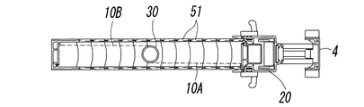
図1〜図3に示すように、本発明に係るスクリーン装置は、建物開口部等に設置するスクリーン枠1の上部横枠2にガイドされて横移動可能で、防虫用のネットからなるスクリーンの一端が固定されている可動框20及びスクリーンの巻取機能を有する巻軸30とを有している。該巻軸30は、一対のスクリーン10A,10Bの中間に位置して巻取りスプリング31を内蔵し、両スクリーン10A,10Bを二重に巻き取るもので、上記可動框20には該巻軸30のスプリング31によってスクリーンの開方向の付勢力が作用している。
As shown in FIGS. 1 to 3, the screen device according to the present invention is guided by an upper
上記スクリーン装置において、上記スクリーン10Aは、一端が上記可動框20に固定され、また、上記スクリーン10Bは、一端がスクリーン枠1の側枠3に固定され、両スクリーンの他端はいずれも上記巻軸30に巻き取られるものである。上記スクリーン10A,10Bの下端及び上記巻軸30の下端は、いずれも、多数のガイド駒51を連結して形成したスクリーンガイド50の上に横移動自在に収容されている。上記スクリーンガイド50は、その一端を可動框20の下端部にある導出入部40を通して該可動框に出入り可能とし、他端を上記側枠3の下端の端蓋60に固定しているが、その一端を側枠3の下端に設けた導出入部40を通して該側枠3内に出入り可能とし、他端を可動框20の下端部に固定することもできる。
In the screen device, one end of the
上記スクリーン枠1の上部横枠2は、図2に示すように、その長手方向に沿う前後両側に下方に伸びる一対の垂下壁2aを有し、該垂下壁2a内のレール2b上に、上記可動框20及び巻軸30の上端部に設けた吊車20a及び吊車30aを転動するようにして、それらが横移動自在に吊られている。更に、上記スクリーン枠1は、上記スクリーン10Bの一端が固定された側枠3に対向させて、スクリーンを展張したときに上記可動框20が衝合する受け枠4が配設され、可動框20との間にそれらの衝合時に相互に係合するラッチ機構を備えている。
一方、上記スクリーン枠の下部に設けたレール状の下部ガイド7は、その上を上記スクリーンガイド50の各ガイド駒51及び可動框20の下端を摺動させるもので、それらの摺動の態様については詳細に後述する。
As shown in FIG. 2, the upper
On the other hand, the rail-shaped
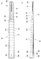
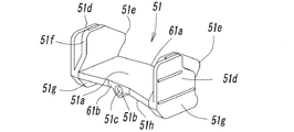
次に、上記スクリーンガイド50の構成について、図6〜図8を参照して詳細に説明する。上記スクリーンガイド50は、図7及び図8に示すガイド駒51の多数を連接したもので、それぞれのガイド駒51は同じ形状を有し、上記スクリーン10A,10B、及び巻軸30の下端を保持するように、底板51aと、該底板51aの両端にある立壁51dとにより、中心線に関して対称な溝形状を有し、上記底板51a及び立壁51dの内表面は上記スクリーン10A,10B及び巻軸30の下端が円滑に摺動できるように平滑な面に形成されている。
Next, the configuration of the
上記ガイド駒51の底板51aは、その中心線方向に凸形の一端側61a(以下、これを前面側と呼ぶ。)が中央部において山形に突出し、逆に、底板51aの他端側61b(以下、これを後面側と呼ぶ。)は、中央部において上記山形とは逆の溝形に凹んでいる。そして、隣接するガイド駒51の底板51aを平らな面上において上記一端側61aと他端側61bとを相互に突き当てると、両ガイド駒51の底板51aの端面がぴたりと一致するように形成し、このような状態でガイド駒51を連結すると、図6(a)のスクリーンガイド50が紙面内において湾曲しない状態に形成され、そのため、巻軸30の下端をこのスクリーンガイド50において保持させた場合には、スクリーンに対して風等の作用があってもそれに対向できる強度をスクリーンガイド50により保たせることができる。また、上記底板51aの裏面の中央部には、内部に可撓性のワイヤー54を通すための通孔51cが設けられた凸部51bが形成されている。
In the
上記ガイド駒51の立壁51dは、底板51aより上の部分において外側片と内側片とが接合された形態を有し、該立壁51dの前面側には内側片が突出する凸部51eが、後面側には内側片が後退した凹部51fがあり、隣接する両ガイド駒51の底板51aの端面をぴたりと一致させたとき、上記前面側の内側片の凸部51eが隣接するガイド駒51の後面側の内側片の凹部51fに嵌り込み、その状態では、隣接するガイド駒51がそれぞれ上に凹になる方向には屈曲自在で、この場合には突出する内側片及び底板51aのずれ動きによる部分的な当接で屈曲範囲が制限されるが、逆方向には、上記突出及び後退した内側片の周縁並びに底板51aの端面の接触によって相互に屈曲しないように形成されている。
The standing
また、上記構成により、多数のガイド駒51を連結するワイヤー54が該ガイド駒51の底板51aに設けた通孔51cに挿通され、隣接する上記ガイド駒51の立壁51dの外側片と内側片との間に常に相互に重なり合う部分があって、該立壁が隙間なく連接された状態になるので、隣接ガイド駒51が相互に屈曲して可動框20に導出入される場合などにおいても、隣接ガイド駒51の底板51a間及び立壁51d間の一部に大きな隙間が生じて、スクリーンや異物が挟まれたりするようなことがない。
In addition, with the above configuration, the
上記ガイド駒51の立壁51dの下部には、上記底板51aよりも下方に伸びて、このガイド駒51を連接したスクリーンガイド50がレール状の下部ガイド7に沿ってその上を移動するとき、該下部ガイド7の両側縁に係合して該下部ガイドから脱線するのを抑止するガイド壁51gを凸設している。従って、特別の外乱がない限り、上記ガイド壁51gによりガイド駒51がレール状の下部ガイド7から外れることがなく、上記スクリーンガイド50はレール状の下部ガイド7に沿って安定的に走行することになる。また、上記各ガイド駒51の底板51aの下面には、その前面側から後面側に向けて小さい突条51hを設けている。この突条51hは、上記ガイド駒51を下部ガイド7の平坦な上面に沿って摺動させるとき、格別の抵抗を受けることなく円滑に摺動させるために有効なものである。
なお、上記ガイド駒51の底板51aの中央に形成された凸部51bは、上記下部ガイド7の中央にある窪み内に収まるようにするなど、それが障害になるのを避ける必要がある。
Under the standing
In addition, it is necessary to avoid that the
図1及び図6に示すように、上記スクリーンガイド50の一端側において、連接したガイド駒51の端部に連結しているバネ保持部材52は、上記可動框20の下端の導出入部40から該可動框20内に導出入するスクリーンガイド50の一端側に連結したもので、該バネ保持部材52は、上記スクリーンガイド50を構成する多数のガイド駒51における通孔51cに挿通したワイヤー54に緊張力を与えるためのバネ53を保持できるように構成している。即ち、該バネ保持部材52は、その先端部にバネ53の一端を固定するネジ52aが螺挿され、反対側の基端には上記バネ53で引張するワイヤー54を通すための通孔52bが設けられ、該バネ保持部材52自体は上記バネ53を保持させるに必要な長さに形成されている。上記スクリーンガイド50は、上記可動框20が横移動するのに伴って、該可動框20の下端の導出入部40から該可動框20内に出入りするものである。
As shown in FIGS. 1 and 6, on one end side of the
特に、ガイド駒51の底板の一端側が山形に突出し、他端側が該山形とは逆の溝形に凹んで、隣接するガイド駒の底板の端面を相互に接触させたときに両端面が一致するように形成したうえで、多数のガイド駒51を連結するワイヤー54の一端にバネ53の付勢力を作用させると、多数のガイド駒51の連接面が密接状態に圧接されるので、スクリーンガイド50がそれ自体を直線状態に保持するための大きな強度を持つことになる。
In particular, one end side of the bottom plate of the
上記スクリーンガイド50は、各ガイド駒51における前記通孔51cに一連のワイヤー54を挿通したうえで、側枠3の下端の端蓋60に該ワイヤー54の一端を固定し(図6参照)、該ワイヤー54の他端を、上記バネ保持部材52に隣接したガイド駒51の通孔51cに挿通したうえで、更に上記バネ保持部材52の通孔52bに挿通し、その先端に取り付けた掛け具56に、一端を上記ネジ52aでバネ保持部材52に取り付けたバネ53の他端を連結している。そのため、上記バネ保持部材52、多数のガイド駒51の各連結端相互間、及び上記端蓋60との間が、上記バネ53の付勢力で互いに圧接された状態に保持され、ガイド駒51が相互に直線状をなす状態で強固に結合される。
The
なお、上記バネ保持部材52のスクリーンガイド50が連結される基端側は、該バネ保持部材52に隣接するガイド駒51の底板51aの前面側と隙間無く接し、また、上記バネ保持部材52の基端側には、バネ保持部材52に隣接するガイド駒51の底板51aの表面と連結する連結片52cが設けられている。
The base end side of the
一方、上記スクリーンガイド50の他端の固定は、図6に示すように、上記側枠3の下端の端蓋60の底板60aにおけるスクリーンガイド50との連結端60bを、該スクリーンガイド50の端部ガイド駒51における底板51a及び立壁51dの連結端と密接するような形態に形成し、また、上記端蓋60の底板60aの下面には、ガイド駒51における底板下面の通孔51cを有する凸部51bと同様な形態の通孔60d及び凸部60cを設けている。上記底板60aの通孔60dは、ガイド駒51の通孔51cに連通したうえで、該ガイド駒51の通孔51cに挿通したワイヤー54の端部を挿入して、その先端に固定リング60eを圧嵌することにより、ワイヤー54の端部を固定するものである。従って、上記バネ保持部材52に一端を固定した上記バネ53の付勢力により、ワイヤー54を介して連接された多数のガイド駒51が、上記バネ保持部材52と上記端蓋60との間で相互に押圧されることになる。
On the other hand, the other end of the
このように、隣接するガイド駒51同士がバネ53により互いに押圧されると、ガイド駒51間に余分な隙間ができないだけでなく、多数のガイド駒51が整然と整列することになり、そのため、上記可動框20に出入りするガイド駒51が該可動框20の一部に引っ掛かったりすることがなく、上記可動框20が円滑に上記下部ガイド7上を横移動することが可能となる。また、上記バネ保持部材52、ガイド駒51、端蓋60が直線状に連接され、多数のガイド駒51が上記下部ガイド7上に直線状に配設し、しかも、その直線状配列に保持する保持力を高くすることができる。
As described above, when the
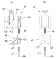
上記スクリーンガイド50は、可動框20の下端部にある導出入部40を通して該可動框に出入り可能なものであるが、該導出入部40は、図4及び図5から分かるように、可動框20の下端部に固定した本体部材41と、上記スクリーンガイド50が可動框20に出入りする際に隣接ガイド駒51が屈曲するのをガイドする傾斜曲面42bをもった転向ガイド42とを備えている。上記本体部材41は、可動框20内にボルト45によって固定されたものであり、該本体部材41には、上記転向ガイド42の抜止め43aを下端に有する支持棒43を、本体部材41内において下方に突出するように固定して、上記転向ガイド42を該支持棒43に沿って昇降するようにガイドさせ、該支持棒43に外嵌させて本体部材41と転向ガイド42との間に配設したバネ44の付勢力により、該転向ガイド42が下方に押圧させている。
The
図4(a)は、上記転向ガイド42の支持棒挿入部42cの上端が本体部材41に当接した最上位置にある状態を示し、図4(b)は、上記転向ガイド42がバネ44の付勢力により最下位置である支持棒43の抜止め43aに当接した状態を示し、両図の範囲内で下部ガイド7の高さの変動に対して転向ガイド42の位置を追随させることができる。
4A shows a state in which the upper end of the support
上記導出入部40の構成について具体的に説明すると、該導出入部40の本体部材41は、該本体部材41を上記可動框20の下端部にボルト45によって固定するための固定部41aと、上記スクリーンガイド50を導出入する導出入口41bと、該スクリーンガイド50を可動框20内の上部に出し入れする導通口41cと、上記転向ガイド42を上下動自在に収容すると共に、上記スクリーンガイド50のガイド駒51を通過させるための空孔を形成する中間孔41dと、該本体部材41に上記転向ガイド42を上下動可能に支持するための上記支持棒43を固定する支持棒固定部41eとを有している。
The configuration of the lead-in /
上記導出入部40の本体部材41に対してバネ44の付勢力により下方に押圧された転向ガイド42は、その下面が常に上記下部ガイド7に接する位置にあり、本体部材41におけるスクリーンガイド50の導出入口41bと、該スクリーンガイド50を可動框20内の上部に出し入れする導通口41cとの間に配設される傾斜曲面42bを有している。この傾斜曲面42bは、スクリーンガイド50が屈曲して転向するのに適した円弧状面により構成され、該傾斜曲面42bの導出入口41b側の下端は、下部ガイド7に接するような曲面に形成され、また、該傾斜曲面42bの上端側は、上記本体部材41の導通口41cに接するように形成されている。更に、上記転向ガイド42の下部ガイド7に接する下面の幅方向両側には、該下部ガイド7の両側縁に係合して常に上記転向ガイド42が下部ガイド7上から脱出しないようにするためのガイド壁42fを設けている。
The turning
上記可動框20は、上端が吊車20aにより上部横枠2に吊下されているため、下部ガイド7が平坦面上に設けられていないとき、つまり、上部横枠2のレール2bの表面と下部ガイド7の表面との間の長さに部分的な変動がある場合には、下部ガイド7の凹凸に応じて可動框20が該下部ガイド7に対して昇降し、可動框20の下端のガイドが不安定になるが、上述したように、可動框20の下端の導出入部40における本体部材41に、バネ44の付勢力により下方に押圧された転向ガイド42を設けているので、該転向ガイド42により下部ガイド7上を移動するスクリーンガイド50を円滑に可動框20内に導出入できるばかりでなく、上記ガイド壁51gの存在により可動框20の下端を常に安定的に下部ガイド7によりガイドさせることができる。
Since the upper end of the
以上、本発明に係るスクリーン装置について説明してきたが、本発明に係るスクリーン装置は上記の実施形態に限定されることなく、特許請求の範囲の趣旨を逸脱しない範囲で様々な設計変更が可能であることは言うまでもない。 The screen device according to the present invention has been described above. However, the screen device according to the present invention is not limited to the above-described embodiment, and various design changes can be made without departing from the scope of the claims. Needless to say.
2 上部横枠
3 側枠
4 受け枠
7 下部ガイド
10A,10B スクリーン
20 可動框
30 巻軸
42 下部ガイド
50 スクリーンガイド
51 ガイド駒
53 バネ
54 ワイヤー
2 Upper
Claims (3)
上記スクリーンガイドを構成するガイド駒が、上記スクリーン及び巻軸の下端をガイドするための、底板と該底板を挟んで対向する一対の立壁とにより形成された溝形状を有し、各ガイド駒の底板の中心線方向の一端側が中央部において山形に突出し、逆に、該底板の他端側が中央部において上記山形とは逆の溝形に凹んでいて、隣接するガイド駒の底板の端面を相互に接触させたときに両端面が一致するように形成され、
上記多数のガイド駒が、それらを貫通する可撓性のワイヤーにより連結され、上記ワイヤーの一端にバネを介装することにより該ワイヤーにバネの付勢力を作用させて、多数のガイド駒の連接面が互いに圧接されている、
ことを特徴するスクリーン装置。 A spring for winding the screen, which is also guided laterally by the upper horizontal frame, between one side frame of the screen frame and a movable rod guided laterally by the upper horizontal frame of the screen frame. The one end of the pair of screens is fixed to the winding shaft, the other end of one screen is a movable rod, and the other is fixed to the other end of the pair of screens. The other end of the screen is fixed to the side frame of the screen frame, and a pair of screens are wound around the winding shaft, and a large number of guide pieces for guiding the lower end of the screen and the winding shaft are respectively placed on the upper side. One end of a flexible screen guide that is flexibly connected to the recess is moved into and out of the one side frame and the movable rod from the lead-in / out portion at the lower end with the lateral movement of the movable rod. Possible In the screen device which is fixed to the other of the lower end of the side frame and the movable rail and the other end of the screen guide,
The guide piece constituting the screen guide has a groove shape formed by a bottom plate for guiding the lower end of the screen and the winding shaft and a pair of standing walls facing each other across the bottom plate, and the bottom plate of each guide piece One end side of the center line direction protrudes in a chevron shape at the central portion, and conversely, the other end side of the bottom plate is recessed in a groove shape opposite to the chevron shape at the central portion, and the end surfaces of the bottom plates of adjacent guide pieces contact each other Formed so that both end faces match when
The multiple guide pieces are connected by a flexible wire that passes through them, and a spring is applied to one end of the wire so that a biasing force of the spring acts on the wire. Are in pressure contact with each other,
A screen device characterized by that.
上記可動框の下端の幅方向両側、及びスクリーンガイドにおける各ガイド駒の底板下面の幅方向両側に、上記下部ガイドの両側縁に係合して上記ガイド駒が下部ガイド上から外れないようにするためのガイド壁を設けている、
ことを特徴とする請求項1に記載のスクリーン装置。 A rail-shaped lower guide that guides the lower end of the movable rod and the lower surface of the screen guide at the lower part of the screen frame,
To engage the both side edges of the lower guide on both widthwise sides of the lower end of the movable rod and on the widthwise sides of the bottom surface of the bottom plate of each guide piece in the screen guide so that the guide pieces do not come off the lower guide. The guide wall is provided,
The screen device according to claim 1.
ことを特徴とする請求項1または2に記載のスクリーン装置。 A wire connecting a large number of guide pieces is inserted into a through hole provided in the bottom plate of the guide piece, and there are always overlapping portions on the standing walls of the adjacent guide pieces, and the standing walls are connected without gaps.
The screen device according to claim 1, wherein the screen device is a screen device.
Priority Applications (1)
| Application Number | Priority Date | Filing Date | Title |
|---|---|---|---|
| JP2012240346A JP5792145B2 (en) | 2012-10-31 | 2012-10-31 | Screen device |
Applications Claiming Priority (1)
| Application Number | Priority Date | Filing Date | Title |
|---|---|---|---|
| JP2012240346A JP5792145B2 (en) | 2012-10-31 | 2012-10-31 | Screen device |
Publications (2)
| Publication Number | Publication Date |
|---|---|
| JP2014088736A true JP2014088736A (en) | 2014-05-15 |
| JP5792145B2 JP5792145B2 (en) | 2015-10-07 |
Family
ID=50790835
Family Applications (1)
| Application Number | Title | Priority Date | Filing Date |
|---|---|---|---|
| JP2012240346A Active JP5792145B2 (en) | 2012-10-31 | 2012-10-31 | Screen device |
Country Status (1)
| Country | Link |
|---|---|
| JP (1) | JP5792145B2 (en) |
Cited By (5)
| Publication number | Priority date | Publication date | Assignee | Title |
|---|---|---|---|---|
| JP2016223245A (en) * | 2015-06-03 | 2016-12-28 | セイキ住工株式会社 | Barrier-free type horizontally pulled roll screen device |
| JP2017002477A (en) * | 2015-06-04 | 2017-01-05 | セイキ住工株式会社 | Barrier-free horizontal roll screen device |
| EP3517805A1 (en) | 2018-01-29 | 2019-07-31 | Auto-Motion Shade Inc. | Chain for a shield device |
| JP2020051056A (en) * | 2018-09-25 | 2020-04-02 | セイキ販売株式会社 | Horizontal screen device |
| TWI768537B (en) * | 2020-11-06 | 2022-06-21 | 清展科技股份有限公司 | Screen with shielding device and shielding device |
Citations (1)
| Publication number | Priority date | Publication date | Assignee | Title |
|---|---|---|---|---|
| JP2005023578A (en) * | 2003-06-30 | 2005-01-27 | Seiki Hanbai Co Ltd | End part guide of storable stretching surface member |
-
2012
- 2012-10-31 JP JP2012240346A patent/JP5792145B2/en active Active
Patent Citations (1)
| Publication number | Priority date | Publication date | Assignee | Title |
|---|---|---|---|---|
| JP2005023578A (en) * | 2003-06-30 | 2005-01-27 | Seiki Hanbai Co Ltd | End part guide of storable stretching surface member |
Cited By (5)
| Publication number | Priority date | Publication date | Assignee | Title |
|---|---|---|---|---|
| JP2016223245A (en) * | 2015-06-03 | 2016-12-28 | セイキ住工株式会社 | Barrier-free type horizontally pulled roll screen device |
| JP2017002477A (en) * | 2015-06-04 | 2017-01-05 | セイキ住工株式会社 | Barrier-free horizontal roll screen device |
| EP3517805A1 (en) | 2018-01-29 | 2019-07-31 | Auto-Motion Shade Inc. | Chain for a shield device |
| JP2020051056A (en) * | 2018-09-25 | 2020-04-02 | セイキ販売株式会社 | Horizontal screen device |
| TWI768537B (en) * | 2020-11-06 | 2022-06-21 | 清展科技股份有限公司 | Screen with shielding device and shielding device |
Also Published As
| Publication number | Publication date |
|---|---|
| JP5792145B2 (en) | 2015-10-07 |
Similar Documents
| Publication | Publication Date | Title |
|---|---|---|
| JP5792145B2 (en) | Screen device | |
| US8662135B2 (en) | String-guiding structure for a curtain-reeling device | |
| CN100570121C (en) | Winding-up screen device | |
| JP2014152603A (en) | Blind | |
| US20090266495A1 (en) | Foldable screen device | |
| AU2009258684B2 (en) | Screen apparatus | |
| US8316913B2 (en) | Sliding screen door | |
| CN104884725B (en) | The sliding guidance frame portion of proscenia | |
| US8191601B2 (en) | Screen device | |
| US9834972B2 (en) | Anti-jumping upper wheel device with double dampers | |
| JP2019529757A (en) | Safety lock device for storage furniture | |
| US10619409B2 (en) | Transmission device for cordless window shades | |
| US20150184451A1 (en) | Control assembly for cordless curtain asembly | |
| US20080053629A1 (en) | Net Guide for Screen Door | |
| JP5792144B2 (en) | Screen device | |
| JP2017179843A (en) | Roll screen device | |
| JP6469530B2 (en) | Barrier-free horizontal roll screen device | |
| JP4956236B2 (en) | Screen device | |
| JP6426534B2 (en) | Barrier-free type horizontal pulling roll screen device | |
| JP5496867B2 (en) | Horizontal pull screen device | |
| CN205858001U (en) | Vertical hinged door holder | |
| JP2012251309A (en) | Screen device | |
| EP3363986B1 (en) | Handling system for mobile screen curtains | |
| CN202249699U (en) | Reciprocating type window screen lock and invisible window screen using same | |
| JP6665008B2 (en) | Screen device |
Legal Events
| Date | Code | Title | Description |
|---|---|---|---|
| A621 | Written request for application examination |
Free format text: JAPANESE INTERMEDIATE CODE: A621 Effective date: 20140827 |
|
| A977 | Report on retrieval |
Free format text: JAPANESE INTERMEDIATE CODE: A971007 Effective date: 20150723 |
|
| TRDD | Decision of grant or rejection written | ||
| A01 | Written decision to grant a patent or to grant a registration (utility model) |
Free format text: JAPANESE INTERMEDIATE CODE: A01 Effective date: 20150728 |
|
| A61 | First payment of annual fees (during grant procedure) |
Free format text: JAPANESE INTERMEDIATE CODE: A61 Effective date: 20150805 |
|
| R150 | Certificate of patent or registration of utility model |
Ref document number: 5792145 Country of ref document: JP Free format text: JAPANESE INTERMEDIATE CODE: R150 |
|
| R250 | Receipt of annual fees |
Free format text: JAPANESE INTERMEDIATE CODE: R250 |
|
| R250 | Receipt of annual fees |
Free format text: JAPANESE INTERMEDIATE CODE: R250 |
|
| R250 | Receipt of annual fees |
Free format text: JAPANESE INTERMEDIATE CODE: R250 |
|
| S531 | Written request for registration of change of domicile |
Free format text: JAPANESE INTERMEDIATE CODE: R313531 |
|
| R350 | Written notification of registration of transfer |
Free format text: JAPANESE INTERMEDIATE CODE: R350 |
|
| R250 | Receipt of annual fees |
Free format text: JAPANESE INTERMEDIATE CODE: R250 |
|
| R250 | Receipt of annual fees |
Free format text: JAPANESE INTERMEDIATE CODE: R250 |