JP2012251309A - Screen device - Google Patents
Screen device Download PDFInfo
- Publication number
- JP2012251309A JP2012251309A JP2011122826A JP2011122826A JP2012251309A JP 2012251309 A JP2012251309 A JP 2012251309A JP 2011122826 A JP2011122826 A JP 2011122826A JP 2011122826 A JP2011122826 A JP 2011122826A JP 2012251309 A JP2012251309 A JP 2012251309A
- Authority
- JP
- Japan
- Prior art keywords
- screen
- hole
- slide guide
- guide frame
- pair
- Prior art date
- Legal status (The legal status is an assumption and is not a legal conclusion. Google has not performed a legal analysis and makes no representation as to the accuracy of the status listed.)
- Granted
Links
- 238000005452 bending Methods 0.000 description 4
- 241000238631 Hexapoda Species 0.000 description 3
- 239000000077 insect repellent Substances 0.000 description 2
- 238000009434 installation Methods 0.000 description 2
- 238000005192 partition Methods 0.000 description 2
- 230000002093 peripheral effect Effects 0.000 description 2
- 239000004744 fabric Substances 0.000 description 1
- 230000001771 impaired effect Effects 0.000 description 1
- 239000000463 material Substances 0.000 description 1
- 238000000034 method Methods 0.000 description 1
- 239000011347 resin Substances 0.000 description 1
- 229920005989 resin Polymers 0.000 description 1
Images


Landscapes
- Extensible Doors And Revolving Doors (AREA)
Abstract
Description
本発明は、カーテン、ブラインド、網戸、さらに間仕切りなどとして用いることのできる多用途のスクリーン装置に関する。 The present invention relates to a versatile screen device that can be used as a curtain, a blind, a screen door, and a partition.
カーテン、ブラインドなどの遮光および調光手段や網戸、間仕切りなどとして使用する際の設置の制約を解消し、スムーズで安定した開閉操作を実現する装置として、本出願人は、スクリーン装置を提供している(特許文献1)。 The present applicant provides a screen device as a device that eliminates the restrictions of installation when used as light shielding and light control means such as curtains and blinds, screen doors, partitions, etc., and realizes a smooth and stable opening and closing operation. (Patent Document 1).
特許文献1に記載したスクリーン装置では、対向配置された、少なくとも一方がスライド移動可能な一対のスクリーン取付枠部に、スクリーンが、両スクリーン取付枠部間に収縮および展開自在に取り付けられている。また、スクリーン取付枠部への取付側ではないスクリーンの両端部付近には、スライドガイド枠部が一対配設されている。このスライドガイド枠部は、対向配置された一対の側壁部とこの側壁部を相互に繋ぐ架橋部とを有する剛性ユニットが、隣り合う2つにおいて回動自在に連設されて形成される。そして、スライドガイド枠部は、屈曲性を有し、少なくとも一端が自由端とされてスクリーン取付枠部内に収納および引き出し可能とされている。スクリーン取付枠部のスライド移動にともなってスクリーン取付枠部から引き出されたスライドガイド枠の部分は直線性を保持する。このようなスライドガイド枠部によって、設置の制約の解消とスムーズで安定した開閉操作を実現している。 In the screen device described in Patent Document 1, a screen is attached to a pair of screen mounting frame portions, which are arranged to face each other and at least one of which is slidable, so that the screen can be contracted and expanded between both screen mounting frame portions. In addition, a pair of slide guide frame portions are disposed in the vicinity of both ends of the screen that are not attached to the screen mounting frame portion. The slide guide frame is formed by a rigid unit having a pair of side walls arranged opposite to each other and a bridging part connecting the side walls to each other so as to be rotatable in adjacent two. The slide guide frame portion is flexible, and at least one end is a free end so that the slide guide frame portion can be stored and pulled out in the screen mounting frame portion. The portion of the slide guide frame pulled out from the screen mounting frame portion with the sliding movement of the screen mounting frame portion maintains linearity. By such a slide guide frame part, the restriction of installation is eliminated and a smooth and stable opening / closing operation is realized.
上記スクリーン装置は、たとえば窓やドア枠などの開口部の大きさに合わせて所望の大きさのものに作製することができるが、大型のもの、特に開閉方向の幅、すなわち、スクリーン取付枠部のスライド移動方向の幅が大きいものの場合、以下のような問題が指摘される。 The screen device can be manufactured to have a desired size according to the size of an opening such as a window or a door frame, for example, but it is large, particularly a width in the opening / closing direction, that is, a screen mounting frame portion. The following problems are pointed out when the width of the slide movement direction is large.
スクリーンが展開され、スクリーン装置が閉まっている状態において強い風を受けると、スクリーンが風圧によって大きく撓むことがある。このようにスクリーンが大きく撓むと、スライドガイド枠部との間に大きな隙間が形成され、遮光性、防虫性などのスクリーン装置の機能が損なわれる。 When the screen is unfolded and the screen device is closed, the screen may be greatly bent by the wind pressure when receiving strong wind. When the screen is greatly bent as described above, a large gap is formed between the slide guide frame portion, and the functions of the screen device such as light shielding property and insect-proofing property are impaired.
また、スライドガイド枠部がスクリーンの上下両端部付近に配設されたスクリーン装置では、スクリーン取付枠部から引き出された上側のスライドガイド枠部の部分は、スクリーンが有する剛性によって下方から支持されるようにしているが、開閉方向の幅が大きくなるにつれ、スクリーン取付枠部から引き出された上側のスライドガイド枠部の部分が長くなるので、自重により撓むことが予想される。このスライドガイド枠部の撓みは、スクリーン装置の開閉操作に支障をきたすことになる。 Further, in the screen device in which the slide guide frame portion is disposed near the upper and lower ends of the screen, the upper slide guide frame portion drawn out from the screen mounting frame portion is supported from below by the rigidity of the screen. However, as the width in the opening / closing direction increases, the upper slide guide frame portion drawn out from the screen mounting frame portion becomes longer, so that it is expected to be bent by its own weight. This bending of the slide guide frame part hinders the opening / closing operation of the screen device.
そこで、本出願人は、スクリーンの表裏両側に対向配置された一対の方立てが、連結部材によって連結され、スクリーンを挟み込んで一対のスライドガイド枠部間に固定され、連結された方立ては、一体としてスクリーン取付枠部のスライド移動方向と平行な方向にスライド移動可能とされているスクリーン装置を提案している(特許文献2)。 Therefore, the present applicant has a pair of vertical supports arranged on both sides of the screen are connected by a connecting member, fixed between a pair of slide guide frame parts with the screen sandwiched therebetween, As a unit, a screen device is proposed that is slidable in a direction parallel to the sliding movement direction of the screen mounting frame (Patent Document 2).
特許文献2に記載したスクリーン装置では、スクリーン取付枠部のスライド移動にともなって連結された方立てがスライド移動し、一対のスクリーン取付枠部間に展開されたスクリーンの面強度を補強する。このため、強い風を受けても風圧によってスクリーンが大きく撓むのが抑制され、スクリーン装置の遮光性、防虫性などの機能が安定して実現される。また、スクリーンの上端部付近に配設された上側のスライドガイド枠部が自重により撓むのも抑制され、スクリーン装置の開閉操作が安定して実現される。 In the screen device described in Patent Document 2, the connected frame slides as the screen mounting frame portion slides, and reinforces the surface strength of the screen developed between the pair of screen mounting frame portions. For this reason, even if a strong wind is received, the screen is prevented from being greatly bent by the wind pressure, and functions such as light shielding and insect repellent of the screen device are stably realized. Further, the upper slide guide frame provided near the upper end of the screen is prevented from being bent by its own weight, and the opening / closing operation of the screen device is stably realized.
一方、スクリーンには経時的に汚れなどが生じるため、スクリーンの清掃や新品のスクリーンへの交換が必要であり、スクリーンを容易に取り外せることがスクリーン装置に要求される。この点を考慮すると、特許文献2に記載したスクリーン装置では、スクリーンの表裏両側に対向配置された一対の方立てがスクリーンを挟み込んでおり、しかも、方立ては互いに連結部材によって連結されているので、スクリーンの取り外しの際に方立てを分離する必要があり、スクリーンの取り外しは必ずしも容易ではないことが指摘される。 On the other hand, since the screen is contaminated with time, the screen needs to be cleaned or replaced with a new screen, and the screen device is required to be easily removable. Considering this point, in the screen device described in Patent Document 2, a pair of vertical frames arranged opposite to each other on both the front and back sides of the screen sandwich the screen, and the vertical frames are connected to each other by a connecting member. It is pointed out that the screen needs to be separated when removing the screen, and that the removal of the screen is not always easy.
本発明は、以上のとおりの事情に鑑みてなされたものであり、風圧によるスクリーンの撓みとスライドガイド枠部の自重による撓みを抑制することができ、しかも、スクリーンの取り外しが容易であるスクリーン装置を提供することを課題としている。 The present invention has been made in view of the circumstances as described above, and can suppress screen deflection due to wind pressure and deflection due to the weight of the slide guide frame portion, and the screen device can be easily removed. It is an issue to provide.
上記の課題を解決するために、本発明のスクリーン装置は、対向配置された、少なくとも一方がスライド移動可能な一対のスクリーン取付枠部に、スクリーンが、両スクリーン取付枠部間に収縮および展開自在に取り付けられ、一対のスクリーン取付枠部間に張設された張力部材がスクリーンを貫通し、スクリーン取付枠部への取付側ではないスクリーンの両端部付近にスライドガイド枠部が一対配設され、スライドガイド枠部は、複数のスライドガイド枠部ユニットが連結ユニットを介して連結されて形成され、連結ユニットは、一対のスライドガイド枠部において対向配置され、各スライドガイド枠部ユニットは、対向配置された一対の側壁部と両側壁部を相互に繋ぐ架橋部とを有する剛性ユニットが隣り合う2つにおいて回動自在に連設されて形成され、スライドガイド枠部は、屈曲性を有し、少なくとも一端が自由端とされてスクリーン取付枠部内に収納および引き出し可能とされる一方、スクリーン取付枠部のスライド移動にともなってスクリーン取付枠部から引き出されたときにスライドガイド枠部の引き出された部分は直線性を保持するスクリーン装置において、スクリーンの表裏面のいずれか片側においてスクリーンと張力部材の間に1本の方立てが、一対のスライドガイド枠部に架け渡されて配設され、方立ては、その一端および他端において連結ユニットに取り外し自在に固定され、連結ユニットは、対向配置された一対の側壁部と両側壁部を相互に繋ぐ架橋部とを有し、架橋部には、幅の狭い第1孔と、この第1孔に連続する幅の広い第2孔とが形成され、第2孔の内側には、第2孔を開閉自在とした弾性を有する舌片が配設され、方立ての一端および他端に取り付けられる固定部材を第1孔から第2孔にスライドさせ、舌片が押し曲げられることによって、方立ては連結ユニットから固定が解除されることを特徴とする。 In order to solve the above-described problems, a screen device according to the present invention has a pair of screen mounting frame portions that are arranged to face each other and are slidable at least one, and the screen can be contracted and expanded between both screen mounting frame portions. A tension member stretched between a pair of screen mounting frame portions penetrates the screen, and a pair of slide guide frame portions are disposed near both ends of the screen that are not on the side of attachment to the screen mounting frame portion, The slide guide frame unit is formed by connecting a plurality of slide guide frame unit units via a connection unit, the connection units are arranged to face each other in a pair of slide guide frame units, and each slide guide frame unit is arranged to face each other. A rigid unit having a pair of side wall portions and a bridging portion that connects both side wall portions to each other is rotatably connected in two adjacent units. The slide guide frame portion has flexibility and at least one end is a free end so that the slide guide frame portion can be stored in and pulled out of the screen mounting frame portion. In the screen device in which the portion of the slide guide frame portion that is pulled out from the mounting frame portion retains linearity, there is a single stand between the screen and the tension member on either one of the front and back surfaces of the screen. The support frame is detachably fixed to the connecting unit at one end and the other end thereof, and the connecting unit includes a pair of side wall portions and both side walls arranged opposite to each other. A bridging part that connects the parts to each other, and the bridging part is formed with a narrow first hole and a wide second hole that is continuous with the first hole, Inside the two holes, a tongue piece having elasticity that allows the second hole to be opened and closed is disposed, and a fixing member attached to one end and the other end of the vertical frame is slid from the first hole to the second hole, When the piece is pushed and bent, the vertical structure is released from the connection unit.
このスクリーン装置においては、張力部材を挟んで方立てと隙間をあけてもう1本の方立てが配設され、もう1本の方立ても、方立てと同じように、その一端および他端において連結ユニットに取り外し自在に固定され、両方立てが、弾性を有する架橋部材によって連結されていることが好ましい。 In this screen device, another vertical frame is disposed with a tension member sandwiched between the vertical frame and the other vertical frame at one end and the other end in the same manner as the vertical frame. It is preferable that the two standing stands are connected to each other by an elastic bridging member that is detachably fixed to the connecting unit.
本発明のスクリーン装置によれば、風圧によるスクリーンの撓みとスライドガイド枠部の自重による撓みを抑制することができ、しかも、スクリーンの取り外しが容易となる。 According to the screen device of the present invention, it is possible to suppress the bending of the screen due to the wind pressure and the bending due to the weight of the slide guide frame portion, and it becomes easy to remove the screen.
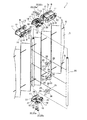
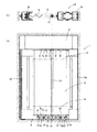
図1(a)(b)は、それぞれ、本発明のスクリーン装置の第1実施形態を示した正面図、上部断面図である。図2は、図1(a)(b)に示したスクリーン装置の方立ての周辺部を示した要部分解斜視図である。図3(a)(b)(c)は、それぞれ、図1(a)(b)に示したスクリーン装置の連結ユニットを拡大して示した正面図、平面図、側面図である。 1A and 1B are a front view and an upper cross-sectional view, respectively, showing a first embodiment of a screen device of the present invention. FIG. 2 is an exploded perspective view of a main part showing a peripheral portion of the screen device shown in FIGS. 1 (a) and 1 (b). 3A, 3B, and 3C are a front view, a plan view, and a side view, respectively, showing the connection unit of the screen device shown in FIGS. 1A and 1B in an enlarged manner.
図1(a)(b)および図2に示したスクリーン装置1は、一対のスクリーン取付枠部2a、2bを備えている。スクリーン取付枠部2aは開口部内縁の右側に固定されている。一方、スクリーン取付枠部2bは、開口部内縁の左側に向かって開口部の横方向にスライド移動可能に配設され、両スクリーン取付枠部2a、2bは対向配置されている。開口部内縁の上側には上レール3が開口部の横方向に沿って配設され、スクリーン取付枠部2a、2bの上端部は上レール3の内側に収められている。開口部内縁の下側には下レール4が開口部の横方向に沿って配設されている。可動側のスクリーン取付枠部2bは、上レール3および下レール4に沿って開口部の横方向にスライド移動自在にされている。
The screen device 1 shown in FIGS. 1A and 1B and FIG. 2 includes a pair of screen
スクリーン取付枠部2a、2b間にはネットから形成されたスクリーン5が取り付けられている。スクリーン5は、プリーツ加工によりプリーツが付けられ、スクリーン取付枠部2a、2b間に収縮および展開自在とされている。すなわち、スクリーン取付枠部2bが開口部内縁の左側にスライド移動する際に、スクリーン5は、開口部に展開し、虫などの侵入を阻止する。また、スクリーン5は、スクリーン取付枠部2bが開口部内縁の右側に向かってスライド移動する際に、収縮し、スクリーン取付枠部2a、2b間に折り畳まれ、収納される。
A
なお、スクリーン5は、ネットから形成される他、布、樹脂製のシートなどから形成することもでき、スクリーン装置1の用途に応じて適宜な素材から形成することができる。また、プリーツ加工によるプリーツ以外に、たとえばハニカム構造などによって収縮および展開自在とすることもできる。
The
スクリーン5には、収縮および展開方向に延びる張力部材6が張設されている。張力部材6には、紐、ワイヤーなどの張力が発生する適宜なものを採用することができ、スクリーン5の高さに対応して複数個所に一定間隔で配設することができる。このような張力部材6は、プリーツ状のスクリーン5を収縮および展開方向に貫通し、スクリーン5を支持している。スクリーン5は、張力部材6によって自立性が確保され、また、面強度が高められている。
A
また、スクリーン装置1は、スクリーン5のスクリーン取付枠部2a、2bへの取付側ではない両端部、すなわち、上下両端部付近に、一対のスライドガイド枠部7a、7bを備えている。スライドガイド枠部7a、7bはともに、2本のスライドガイド枠部ユニット8が連結されて形成されている。スライドガイド枠部ユニット8は、複数の剛性ユニット9が連設されて形成され、所定の長さを有している。
Further, the screen device 1 includes a pair of slide
剛性ユニット9は、対向配置された一対の側壁部10と、両側壁部10を相互に繋ぐ架橋部11とを有している。側壁部10には、長さ方向の一端部に外側に突出する突起12が配設され、他端部に突起12が係合可能な貫通孔13が形成されている。また、側壁部10には、突起12に隣接して貫通孔13と反対側に位置し、外側に突出する小突起14が配設されるとともに、貫通孔13に隣接して突起12の側に位置する略三日月状の長孔15が形成されている。このような剛性ユニット9が、隣り合う2つにおいて、突起14を貫通孔13に側壁部10の内側から嵌め込んで係合させ、また、小突起14を長孔15に差し込むことにより回動自在に連設され、スライドガイド枠部ユニット8を形成している。スライドガイド枠部ユニット8は、剛性ユニット9が隣り合う2つにおいて回動自在とされているため、屈曲性を有し、また、小突起14が長孔15の長さ方向の一端に接触し、剛性ユニット9の回動が規制されることによって直線性を保持することができる。スライドガイド枠部ユニット8の直線性の保持のために、剛性ユニット9には、さらに、架橋部11の一端縁部の表面および他端縁部の裏面を切り欠き、段差を設けることができ、小突起14の長孔15への上記接触に併せて段差を重合させ、剛性ユニット9の回動を規制することもできる。
The
このようなスライドガイド枠部ユニット8の2本が、一端部において連結ユニット16によって連結されている。連結ユニット16は、図3(a)(b)(c)に示したように、対向配置された一対の側壁部17と、両側壁部17を相互に繋ぐ架橋部18とを有している。側壁部17には、長さ方向の両端部に外側に突出する突起19が配設され、突起19は、剛性ユニット9の突起12とほぼ同一の形状および大きさを有し、剛性ユニット9の貫通孔13に係合可能とされている。また、側壁部17には、突起19に隣接して端縁側に位置する小突起20が配設されている。小突起20は、剛性ユニット9の長孔15に係合可能とされている。
Two such slide
2本のスライドガイド枠部ユニット8は、それぞれの一端に位置する剛性ユニット9の貫通孔13に連結ユニット16の突起19を内側から嵌め込んで係合させるとともに、長孔15に小突起20を内側から嵌め込んで係合させることにより、連結ユニット16を介して連結され、スライドガイド枠部7a、7bを形成している。このため、両スライドガイド枠部7a、7bは、スライドガイド枠部ユニット8と同様に、屈曲性を有するとともに、直線性の保持が可能になっている。
The two slide
このようなスライドガイド枠部7a、7bは、長さ方向の両端、すなわち、スライドガイド枠部ユニット8において連結ユニット16により連結されていない側の一端が自由端とされ、スクリーン取付枠部2a、2b内に収納および引き出し可能とされている。スクリーン取付枠部2bを開口部内縁の左側に向けて開口部の横方向にスライド移動させると、スライドガイド枠部7a、7bはスクリーン取付枠部2a、2bから引き出され、引き出された部分は直線性を保持する。一方、スクリーン取付枠部2bを開口部内縁の右側に向けてスライド移動させると、スライドガイド枠部7a、7bは、スクリーン取付枠部2a、2bの上端部、下端部において屈曲し、スクリーン取付枠部2a、2bの内部に収納される。このようなスライドガイド枠部7a、7bの収納および引き出しは、また、上レール3および下レール4に沿って行われ、上側のスライドガイド枠部7aの収納および引き出しは、上レール3の下端部の内側において行われる。
Such slide
なお、連結ユニット16は、一対のスライドガイド枠部7a、7bにおいて上下に対向配置されている。
The connecting
そして、図1(a)(b)および図2に示したスクリーン装置1では、スクリーンの表面側においてスクリーン5と張力部材6の間に1本の方立て21が、一対のスライドガイド枠部7a、7bに架け渡されて配設されている。方立て21は、円形のパイプ状の形状を有し、その一端および他端において、固定部材22としてのリベット22aを用いて連結ユニット16に固定されている。方立て21の連結ユニット16との固定は、後述するように、取り外しが自在とされている。
In the screen device 1 shown in FIGS. 1A and 1B and FIG. 2, one
また、スクリーン装置1では、張力部材6を挟んで方立て21と隙間23をあけてもう1本の方立て24が配設されている。方立て24は、方立て21の大きさ、形状および長さと一致している。また、方立て24も、方立て21と同様に、その一端および他端において連結ユニット16にリベット22aを用いて取り外し自在に固定されている。両方立て21、24は、張力部材6が位置しない長さ方向の3カ所において、弾性を有する架橋部材25によって連結されている。
In the screen device 1, another
架橋部材25は、図2に示したように、略C字型の断面を有する筒状の嵌合片部26を2つと、2つの嵌合片部26を連結する平板状の連結片部27とを備えている。架橋部材25では、2つの嵌合片部26は、ともに方立て21、24の外径に一致する内径を有し、嵌合片部26には切欠部28が形成されている。架橋部材25では、切欠部28が対向配置されて2つの嵌合片部26が連結片部27によって連結されている。また、嵌合片部26は、切欠部28を押し広げると、内径が拡大するように弾性変形する。したがって、架橋部材25では、切欠部28を通じて嵌合片部26の内側に方立て21、24を挿入すると、嵌合片部26が、方立て21、24の外周に巻き付くように嵌合し、両方立て21、24が架橋部材25によって連結される。このようにして連結される2本の方立て21、24は、連結片部27の幅に等しい大きさの隙間23があいて配置され、隙間23には張力部材6を通すことができる。
As shown in FIG. 2, the bridging
一対のスライドガイド枠部7a、7bに架け渡されて配設された両方立て21、24は、スクリーン取付枠部1bのスライド移動にともなってスライドガイド枠部7a、7bが収納および引き出されることにより、一体となってスクリーン取付枠部1bのスライド移動方向と平行な方向にスライド移動する。両方立て21、24は、相互の間に隙間23があいていても、架橋部材25による連結によって剛性が高められ、方立て21、24のスライド移動は安定して実現される。両方立て21、24によって、一対のスクリーン取付枠部2a、2b間に展開されたスクリーン5の面強度を補強することができる。このため、開閉方向の幅が大きい大型のスクリーン装置1の場合に、閉めた状態において強い風を受けても、風圧によってスクリーン5が大きく撓むのを抑制することができ、スクリーン装置1の遮光性、防虫性などの機能が安定して実現される。
The double stands 21 and 24 arranged so as to be bridged between the pair of slide
また、上側のスライドガイド枠部7aは、大きく撓むことが抑制されたスクリーン5によって十分支持され、しかも、両方立て21、24によっても支持される。このため、スライドガイド枠部7aのスクリーン取付枠部2a、2bから引き出された部分が自重により撓むのが抑制され、スクリーン装置1の開閉操作が安定して実現される。
Further, the upper slide
また、スクリーン装置1では、図3(a)に示したように、連結ユニット16の架橋部18には、長さ方向の中央部において、幅方向に間隔をあけて第1孔29が2つ形成されている。また、第1孔29に連続して第2孔30が形成されている。第1孔29の幅は狭く、第2孔30の幅は広い。第1孔29の幅は、図2に示したリベット22aの軸部の外径より若干大きく、第2孔30の幅は、リベット22aの頭部の外径より若干大きい。第2孔30の内側には、第1孔29と反対側に位置する端縁から延びる舌片31が配設されている。舌片31の大きさは、第2孔30より若干小さく、第1孔29側の一端は自由端とされている。舌片31は弾性を有しており、押し曲げが可能とされ、第2孔30を開閉自在としている。
Further, in the screen device 1, as shown in FIG. 3A, the bridging
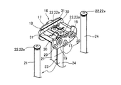
図4は、図1(a)(b)に示したスクリーン装置における連結ユニットからの方立ての固定解除について示した要部斜視図である。図5(a)(b)は、図4に対応する平面図、A−A断面図である。 FIG. 4 is a perspective view of a main part showing the release of the vertical fixing from the connecting unit in the screen device shown in FIGS. 5A and 5B are a plan view corresponding to FIG. 4 and a cross-sectional view taken along line AA.
方立て21、24は、その一端に取り付けられるリベット22aによって上側のスライドガイド枠部7aの連結ユニット16に固定され、また、他端に取り付けられるリベット22aによって下側のスライドガイド枠部7bの連結ユニット16に固定されている。固定状態では、リベット22aの軸部は、連結ユニット16の架橋部18に形成された第1孔29内に位置し、リベット22aの頭部と方立て21、24の一端および他端との間で架橋部18を挟持している。
The
リベット22aを第1孔29から第2孔30にスライドさせると、リベット22aの頭部は舌片31を押し曲げる。すなわち、上側のスライドガイド枠部7aの連結ユニット16では、リベット22aを第1孔29から第2孔30にスライドさせると、リベット22aの頭部が舌片31の下に潜り込み、舌片31を下側から押し上げる。この押し上げによって舌片31は、弾性変形し、上方へと押し曲げられる。また、下側のスライドガイド枠部7bの連結ユニット16では、リベット22aを第1孔29から第2孔30にスライドさせると、リベット22aの頭部が舌片31の上に乗り上がり、舌片31を上側から押し下げる。この押し下げによって舌片31は、弾性変形し、下方へと押し曲げられる。このとき、第2孔30が開放される。第2孔30の幅は、上記のとおり、リベット22aの頭部の外径より若干大きいため、方立て21、24は、連結ユニット30から固定が解除される。上側のスライドガイド枠部7aの連結ユニット16に関しては引き下げることにより、また、下側のスライドガイド枠部7bの連結ユニット16に関しては引き上げることにより、方立て21、24を取り外すことができる。
When the rivet 22a is slid from the
このように、スクリーン装置1では、2本の方立て21、24は、スクリーン5を挟み込んではなく、しかも、固定部材22としてのリベット22aを、スライドガイド枠部7a、7bの連結ユニット16の架橋部18に形成された第1孔29から第2孔30にスライドさせることによって、方立て21、24はスライドガイド枠部7a、7bから工具を用いることなく取り外すことができるので、スクリーン5を取り外す際にそれに先立って行う方立て21、24の取り外しを容易に行うことができる。このため、スクリーン5の取り外しが容易となっている。しかも、両方立て21、24は、上記のとおりの架橋部材25によって連結されているので、架橋部材25の取り外しも工具を用いることなく行うことができ、両方立て21、24の分離も容易である。方立て21、24を取り外した後には、連結ユニット16では、舌片31はその弾性により初期状態に復帰する。第2孔30が閉鎖される。
As described above, in the screen device 1, the two
なお、方立て21、24のスライドガイド枠部7a、7bへの取り付けは、取り外しと逆の手順で行うことができる。方立て21、24の取付状態では、連結ユニット16の架橋部18に形成された第1孔29は、リベット22aの頭部により閉鎖され、また、第2孔30は舌片31によって閉鎖される。このため、第1孔29および第2孔30を通じて光が漏れたり、虫などが侵入することは抑制され、スクリーン装置1の遮光性、防虫性などの機能は安定して実現される。
In addition, attachment to the slide
図6(a)(b)は、それぞれ、本発明のスクリーン装置の第2実施形態を示した正面図、上部断面図である。第2実施形態において第1実施形態と同一の部位については、図6(a)(b)に同一の符号を付し、以下において説明を省略する。 6A and 6B are a front view and an upper cross-sectional view, respectively, showing a second embodiment of the screen device of the present invention. In the second embodiment, the same parts as those in the first embodiment are denoted by the same reference numerals in FIGS. 6A and 6B, and description thereof will be omitted below.
スクリーン装置32では、図1(a)(b)に示したスクリーン装置1における方立て24が省略され、スクリーン5の表面側においてスクリーン5と張力部材6の間に1本の方立て21が、一対のスライドガイド枠部7a、7bに架け渡されて配設されている。方立て21のみであっても、スクリーン装置32では、スクリーン5の面強度を補強することができ、風圧によるスクリーン5の撓みを抑制することができる。また、スクリーン5に支持される上側のスライドガイド枠部7aは、方立て21によって十分に支持可能であり、スライドガイド枠部7aの自重による撓みも抑制することができる。また、スクリーン装置32では、方立て24が省略されているので、スクリーン5の取り外しの際に先立って行う方立て21の取り外しが容易であり、スクリーン5の取り外しがより容易となっている。
In the
本発明は、以上の実施形態によって限定されることはない。スクリーン取付枠部の構造や方立ての形状、張力部材のスクリーンへの通し方などの細部については様々な態様が可能である。また、図1(a)(b)および図6(a)(b)に示したスクリーン装置1、32において、スクリーン取付枠部1aは開口部内縁の右側に固定せず、スクリーン取付枠部1bと同様に、開口部の横方向にスライド移動自在とすることもできる。
The present invention is not limited by the above embodiment. Various aspects are possible for details such as the structure of the screen mounting frame, the shape of the frame, and the way of passing the tension member through the screen. In the
1、32 スクリーン装置
2a、2b スクリーン取付枠部
5 スクリーン
6 張力部材
7a、7b スライドガイド枠部
8 スライドガイド枠部ユニット
9 剛性ユニット
10 側壁部
11 架橋部
16 連結ユニット
17 側壁部
18 架橋部
21、24 方立て
22 固定部材
23 隙間
25 架橋部材
29 第1孔
30 第2孔
31 舌片
DESCRIPTION OF
Claims (2)
スクリーンの表裏面のいずれか片側においてスクリーンと張力部材の間に1本の方立てが、一対のスライドガイド枠部に架け渡されて配設され、方立ては、その一端および他端において前記連結ユニットに取り外し自在に固定され、
前記連結ユニットは、対向配置された一対の側壁部と両側壁部を相互に繋ぐ架橋部とを有し、架橋部には、幅の狭い第1孔と、この第1孔に連続する幅の広い第2孔とが形成され、第2孔の内側には、第2孔を開閉自在とした弾性を有する舌片が配設され、
前記方立ての一端および他端に取り付けられる固定部材を第1孔から第2孔にスライドさせ、舌片が押し曲げられることによって、方立ては連結ユニットから固定が解除される
ことを特徴とするスクリーン装置。 The screen is attached to a pair of screen mounting frames that are arranged to face each other and slidable at least one of the screens so that the screen can be contracted and expanded between both screen mounting frames, and is stretched between the pair of screen mounting frames. A pair of slide guide frame portions are disposed near both ends of the screen that are not attached to the screen mounting frame portion, and the tension member penetrates the screen, and the slide guide frame unit includes a plurality of slide guide frame unit units connected to each other. The connecting units are arranged to face each other in a pair of slide guide frame parts, and each slide guide frame part unit is a bridging part that connects a pair of oppositely arranged side wall parts and both side wall parts to each other. The slide guide frame portion has a flexibility. The slide guide frame portion is pulled out when it is pulled out from the screen mounting frame portion as the screen mounting frame portion slides, while at least one end is a free end and can be stored and pulled out in the screen mounting frame portion. In the screen device that maintains the linearity,
On one of the front and back surfaces of the screen, a vertical stand is arranged between the screen and the tension member so as to span a pair of slide guide frame portions, and the vertical stand is connected to the connecting portion at one end and the other end thereof. Removably fixed to the unit,
The connecting unit includes a pair of side wall portions and a bridge portion that connect both side wall portions to each other. The bridge portion includes a first hole having a narrow width and a width that is continuous with the first hole. A wide second hole is formed, and inside the second hole, an elastic tongue that allows the second hole to be opened and closed is disposed,
The fixing member attached to one end and the other end of the vertical member is slid from the first hole to the second hole, and the tongue is pushed and bent, whereby the vertical member is released from the connection unit. Screen device.
Priority Applications (1)
| Application Number | Priority Date | Filing Date | Title |
|---|---|---|---|
| JP2011122826A JP5715496B2 (en) | 2011-05-31 | 2011-05-31 | Screen device |
Applications Claiming Priority (1)
| Application Number | Priority Date | Filing Date | Title |
|---|---|---|---|
| JP2011122826A JP5715496B2 (en) | 2011-05-31 | 2011-05-31 | Screen device |
Publications (2)
| Publication Number | Publication Date |
|---|---|
| JP2012251309A true JP2012251309A (en) | 2012-12-20 |
| JP5715496B2 JP5715496B2 (en) | 2015-05-07 |
Family
ID=47524365
Family Applications (1)
| Application Number | Title | Priority Date | Filing Date |
|---|---|---|---|
| JP2011122826A Active JP5715496B2 (en) | 2011-05-31 | 2011-05-31 | Screen device |
Country Status (1)
| Country | Link |
|---|---|
| JP (1) | JP5715496B2 (en) |
Cited By (1)
| Publication number | Priority date | Publication date | Assignee | Title |
|---|---|---|---|---|
| WO2016206607A1 (en) * | 2015-06-23 | 2016-12-29 | 金懋实业有限公司 | Expandable bathroom door |
Citations (3)
| Publication number | Priority date | Publication date | Assignee | Title |
|---|---|---|---|---|
| JPS491245Y1 (en) * | 1969-12-27 | 1974-01-12 | ||
| JPS6330803Y2 (en) * | 1983-03-31 | 1988-08-17 | ||
| JP2009293357A (en) * | 2008-06-09 | 2009-12-17 | Metaco Inc | Screen apparatus |
-
2011
- 2011-05-31 JP JP2011122826A patent/JP5715496B2/en active Active
Patent Citations (3)
| Publication number | Priority date | Publication date | Assignee | Title |
|---|---|---|---|---|
| JPS491245Y1 (en) * | 1969-12-27 | 1974-01-12 | ||
| JPS6330803Y2 (en) * | 1983-03-31 | 1988-08-17 | ||
| JP2009293357A (en) * | 2008-06-09 | 2009-12-17 | Metaco Inc | Screen apparatus |
Cited By (1)
| Publication number | Priority date | Publication date | Assignee | Title |
|---|---|---|---|---|
| WO2016206607A1 (en) * | 2015-06-23 | 2016-12-29 | 金懋实业有限公司 | Expandable bathroom door |
Also Published As
| Publication number | Publication date |
|---|---|
| JP5715496B2 (en) | 2015-05-07 |
Similar Documents
| Publication | Publication Date | Title |
|---|---|---|
| JP5358126B2 (en) | Screen device | |
| JP5602995B2 (en) | Screen device | |
| JP5159503B2 (en) | Screen device | |
| JP4794373B2 (en) | Screen device | |
| WO2007063685A1 (en) | Foldable screen device | |
| ES2402900T3 (en) | Window roll up screen | |
| JP5420500B2 (en) | Screen device | |
| JP5715496B2 (en) | Screen device | |
| JP2005023578A (en) | End part guide of storable stretching surface member | |
| JP2012127090A (en) | Horizontal pulling type screen device | |
| JP6665008B2 (en) | Screen device | |
| JP7072227B2 (en) | Horizontally retractable screen device | |
| JP4155950B2 (en) | Horizontal screen door | |
| JP5912262B2 (en) | Building opening screen device | |
| JP2003161089A (en) | Screen device | |
| JP3673209B2 (en) | Double screen device | |
| JP6408430B2 (en) | Barrier-free horizontal roll screen device and its assembly manufacturing and installation method | |
| JP5835755B2 (en) | Projection screen | |
| JP3981558B2 (en) | Door plate storage screen door | |
| JP4704272B2 (en) | Screen device | |
| TW201416542A (en) | Window screen device, chain and chain carrier unit | |
| JP2010203068A (en) | Sliding screen device | |
| JP2005264524A (en) | Horizontally sliding wire screen | |
| JP2002201848A (en) | Parallel moving device for rail |
Legal Events
| Date | Code | Title | Description |
|---|---|---|---|
| A621 | Written request for application examination |
Free format text: JAPANESE INTERMEDIATE CODE: A621 Effective date: 20140217 |
|
| A977 | Report on retrieval |
Free format text: JAPANESE INTERMEDIATE CODE: A971007 Effective date: 20140731 |
|
| A131 | Notification of reasons for refusal |
Free format text: JAPANESE INTERMEDIATE CODE: A131 Effective date: 20140819 |
|
| A521 | Request for written amendment filed |
Free format text: JAPANESE INTERMEDIATE CODE: A523 Effective date: 20140929 |
|
| TRDD | Decision of grant or rejection written | ||
| A01 | Written decision to grant a patent or to grant a registration (utility model) |
Free format text: JAPANESE INTERMEDIATE CODE: A01 Effective date: 20150303 |
|
| A61 | First payment of annual fees (during grant procedure) |
Free format text: JAPANESE INTERMEDIATE CODE: A61 Effective date: 20150313 |
|
| R150 | Certificate of patent or registration of utility model |
Ref document number: 5715496 Country of ref document: JP Free format text: JAPANESE INTERMEDIATE CODE: R150 |
|
| R250 | Receipt of annual fees |
Free format text: JAPANESE INTERMEDIATE CODE: R250 |
|
| R250 | Receipt of annual fees |
Free format text: JAPANESE INTERMEDIATE CODE: R250 |
|
| R250 | Receipt of annual fees |
Free format text: JAPANESE INTERMEDIATE CODE: R250 |
|
| R250 | Receipt of annual fees |
Free format text: JAPANESE INTERMEDIATE CODE: R250 |
|
| R250 | Receipt of annual fees |
Free format text: JAPANESE INTERMEDIATE CODE: R250 |
|
| R250 | Receipt of annual fees |
Free format text: JAPANESE INTERMEDIATE CODE: R250 |
|
| R250 | Receipt of annual fees |
Free format text: JAPANESE INTERMEDIATE CODE: R250 |