JP2014088727A - Soundproof forcible ventilation device corresponding to simple soundproof panel device - Google Patents
Soundproof forcible ventilation device corresponding to simple soundproof panel device Download PDFInfo
- Publication number
- JP2014088727A JP2014088727A JP2012240026A JP2012240026A JP2014088727A JP 2014088727 A JP2014088727 A JP 2014088727A JP 2012240026 A JP2012240026 A JP 2012240026A JP 2012240026 A JP2012240026 A JP 2012240026A JP 2014088727 A JP2014088727 A JP 2014088727A
- Authority
- JP
- Japan
- Prior art keywords
- ventilation
- sound
- soundproof
- soundproof panel
- sound absorbing
- Prior art date
- Legal status (The legal status is an assumption and is not a legal conclusion. Google has not performed a legal analysis and makes no representation as to the accuracy of the status listed.)
- Pending
Links
Images

Landscapes
- Building Environments (AREA)
Abstract
Description
本発明は、簡易型防音パネル対応の防音強制換気装置に関するものである。 The present invention relates to a soundproof forced ventilation device compatible with a simple soundproof panel.
簡易型防音パネルは、例えばある作業箇所において、騒音が発生するときに、その騒音発生源を覆い、積極的に防音するものであり、主要吸音材として、グラスウール・発泡ポリプロピレン等が使用され、その外装を塩化ビニール製遮音シート等で覆って構成されており、軽量で取り扱いやすいことが特徴とされている。 For example, when a noise is generated at a certain work location, the simple type soundproof panel covers the noise generation source and actively performs sound insulation. As a main sound absorbing material, glass wool, foamed polypropylene, etc. are used. The exterior is covered with a vinyl chloride sound insulation sheet, and is characterized by being lightweight and easy to handle.
この簡易型防音パネルは、主に短期的な使用に用いられることが多く、たとえば、作業のたびに設置撤去を繰り返す夜間作業や、長期間の設置ができない場所や短期の設置でよい作業等で、騒音を発生する機械機器などを囲む防音設備として、広く普及されているものである。 This simple type soundproof panel is often used mainly for short-term use.For example, in nighttime work where installation and removal are repeated at every work, in places where long-term installation is not possible, or work that requires short-term installation, etc. As a soundproofing facility that surrounds mechanical equipment that generates noise, it is widely used.
また、建築工事における抗頭処理作業のような、コンクリートをハツル大騒音も作業者ごと囲って防音出来るとのメリットもある。
In addition, there is also an advantage that it is possible to surround the worker with a large noise of the concrete, such as anti-head treatment work in construction work, and to prevent noise by surrounding each worker.
ところで従来、例えば、簡易式防音パネルで覆った内部の給排気を強制的に行う技術については何ら創案されておらず、特開平10−96276号公報に記載された発明の様に、例えば住宅用の防音パネル内に換気機能と防音機能を施したいわゆる防音効果を有する換気パネルが提案されているにすぎなかった。 By the way, conventionally, for example, no technology has been devised for forcibly supplying and exhausting the interior covered with a simple soundproof panel. For example, as in the invention described in Japanese Patent Application Laid-Open No. 10-96276, for example, for housing Only a ventilation panel having a so-called soundproofing effect in which a ventilation function and a soundproofing function are provided in the soundproofing panel has been proposed.
しかしながら、この防音効果を有する換気パネルは、まず、強制的に換気を行う機能は備えておらず、また騒音が発生する箇所などを覆って積極的に防音することを目的として創案された発明ではなかった。 However, the ventilation panel having the soundproofing effect does not have a function to forcibly ventilate first, and in the invention created for the purpose of actively soundproofing covering a place where noise is generated. There wasn't.
なお、前述した騒音が発生する箇所などを覆って積極的に防音することを目的とする本発明のような簡易式防音パネルについての換気対策については、従来では簡易型防音パネルの一部にパネルの外部と内部とを連通させた開口部を穿設し、該開口部によって内部の換気を行うか、あるいは、パネル1枚または必要枚数を換気目的で撤去するか、または、前記簡易式防音パネルに排気穴をあけ、この排気穴に換気ファンや換気風管を接続させ、これによりいわゆる強制換気を行うことが考えられていた。 As for ventilation measures for a simple soundproof panel such as the present invention, which is intended to actively prevent sound by covering a place where noise is generated as described above, a panel is conventionally used as a part of the simple soundproof panel. An opening that allows communication between the outside and the inside is drilled, and the inside is ventilated through the opening, or one panel or a required number of panels is removed for ventilation, or the simplified soundproof panel It has been considered to make a so-called forced ventilation by making an exhaust hole in the exhaust hole and connecting a ventilation fan or ventilation duct to the exhaust hole.
しかしながら、前記の開口部をはじめ、接続した前述のファンや換気風管から音がもれ、これにより防音性能の低下が懸念される。 However, there is a concern that sound may leak from the above-described opening and the connected fan and ventilation wind pipe, thereby reducing the soundproof performance.
また、前記した作動騒音を発する内燃機関への換気対策のほか、従来の強制換気装置を有しない防音パネルでは、いわゆるハツリ作業等の防音に使用する場合においては、粉塵や囲われた内部の温度上昇による環境悪化が生じ、これを解消する手だてがないとの課題があった。 In addition to the above-described ventilation measures for internal combustion engines that generate operating noise, in the case of a conventional soundproof panel that does not have a forced ventilation device, when used for soundproofing such as so-called chipping work, dust or the enclosed internal temperature There was a problem that there was no way to eliminate the environmental deterioration caused by the rise.
さらに、ファンや換気風管を用いた場合には、当該ファンや換気風管を前述の簡易式防音パネルからたとえば内側あるいは外側に突出させて設置せざるを得ないため、内部においての限られた作業スペースでの作業に支障が生じたり、外側の作業通路を塞いだりしてしまうとの課題もあった。
Furthermore, when a fan or ventilation wind pipe is used, the fan or ventilation wind pipe must be installed, for example, inward or outward from the above-described simple soundproof panel. There were also problems that work in the work space would be hindered or the outside work passage would be blocked.
かくして、本発明は前記従来の課題を解決するために創案されたものであり、例えば防音パネルに形成された開口部、あるいはファンや換気風管から音がもれることがなく、また、防音性能の低下もなく、また、いわゆるハツリ作業等の防音に使用される場合でも、作業に伴う粉塵や囲われた内部の温度上昇による環境悪化がなく、さらに、簡易式防音パネルから突出させて前記ファンや換気風管を設置しないため、内部においての限られた作業スペースでの作業に支障が生じたり、外側の作業通路を塞いだりすることがない簡易型防音パネル装置対応防音強制換気装置を提供することを目的とするものである。
Thus, the present invention has been developed to solve the above-described conventional problems. For example, no sound is leaked from an opening formed in the soundproof panel, a fan or a ventilation wind pipe, and the soundproof performance. Even when used for soundproofing such as so-called chiseling work, there is no environmental deterioration due to dust and temperature rise inside the work, and the fan is projected from the simple soundproofing panel. Provide a soundproof forced ventilation system for a simple soundproof panel device that does not interfere with work in a limited work space inside or block the outside work passage. It is for the purpose.
本発明は、表裏面となる一対の方形状板体が、間隔をあけて配置されると共に側面側には連結板体が接続されて内部に略平板状をなす密閉空間が設けられた遮音パネルを形成し、
前記一対の方形状板体には、通風用開口が各々設けられ、前記密閉空間内には前記通風用開口と連通し、前記略平板状をなす密閉空間の空間長手方向へ向かい延出配置された吸音路が設けられ、
前記吸音路内には吸音材が取り付けられると共に該吸音路が曲線とされて高効率吸音路とされ、かつ該吸音路には通風用開口に接して強制ファンが取り付けられ強制通風可能とされた、
ことを特徴とし、
または、
前記強制ファン部材の動力源には、乾電池あるいは充電池が用いられる、
ことを特徴とするものである。
The present invention provides a sound insulation panel in which a pair of rectangular plates serving as front and back surfaces are arranged with a space therebetween, and a connecting plate is connected to the side surface to provide a substantially flat sealed space inside. Form the
The pair of rectangular plates are each provided with a ventilation opening, communicated with the ventilation opening in the sealed space, and arranged to extend in the longitudinal direction of the substantially flat sealed space. Sound absorption path is provided,
A sound absorbing material is attached in the sound absorbing path, and the sound absorbing path is curved to be a high efficiency sound absorbing path, and a forced fan is attached to the sound absorbing path in contact with the ventilation opening to allow forced ventilation. ,
It is characterized by
Or
A dry battery or a rechargeable battery is used as a power source for the forced fan member.
It is characterized by this.
本発明であれば、パネルに形成された開口部や設置するファンや換気風管から音がもれることがないため防音性能の低下もなく、また、いわゆるハツリ作業等の防音に使用される場合でも、作業に伴う粉塵や囲われた内部の温度上昇による環境悪化が生ぜず、さらに、前記ファンや換気風管を簡易式防音パネルからたとえば内側あるいは外側に突出させて設置させることがないため、内部においての限られた作業スペースでの作業に支障が生じたり、外部の作業通路を塞いだりすることがないとの優れた効果を奏する。
According to the present invention, there is no deterioration in soundproofing performance because no sound is leaked from the opening formed in the panel, the fan to be installed, or the ventilation windpipe, and it is used for soundproofing such as so-called chiseling work. However, there will be no environmental degradation due to dust and temperature rise inside the work, and the fan and ventilation wind pipes will not be installed protruding from the simple soundproof panel, for example, inward or outward. There is an excellent effect that work in a limited work space inside is not hindered or an external work passage is not blocked.
以下本発明を図に示す実施例に基づいて説明する。 Hereinafter, the present invention will be described based on embodiments shown in the drawings.
図において、符号1は簡易型防音パネルであり、この簡易型防音パネル1・・・を複数枚接続し、箱形に組み立て簡易型防音パネル装置2を構成する。そしてこの簡易型防音パネル装置2により騒音発生源を覆って密閉し、前記騒音を防音するものとなる。 In the figure, reference numeral 1 denotes a simple soundproof panel, and a plurality of the simple soundproof panels 1... Are connected to form a simple soundproof panel device 2 assembled in a box shape. The simplified soundproof panel device 2 covers and seals the noise generation source to prevent the noise.
ここで、簡易型防音パネル装置2を構成する簡易型防音パネル1は、前述したように、主要吸音材として、グラスウールや発泡ポリプロピレン等を略長方形の板状に形成して使用しており、その外装を塩化ビニール製遮音シート等で覆い、軽量で取り扱いやすいことを特徴としている。 Here, as described above, the simple soundproof panel 1 constituting the simple soundproof panel device 2 uses glass wool, foamed polypropylene or the like as a main sound absorbing material formed in a substantially rectangular plate shape. The exterior is covered with a vinyl chloride sound insulation sheet, and is characterized by being lightweight and easy to handle.
そして、簡易型防音パネル1・・・で構成された簡易型防音パネル装置2は、主に短期的な使用に用いられることが多く、たとえば、作業のたびに設置撤去を繰り返す夜間作業や、長期間の設置ができない場所や短期の設置でよい作業場所等で、騒音を発生する機械機器などを囲む防音設備として、広く普及しているものである。 The simple type soundproof panel device 2 composed of the simple type soundproof panel 1... Is often used mainly for short-term use. It is widely used as a soundproofing facility that surrounds machinery and equipment that generate noise in places where it cannot be installed for a long period of time or work places where short-term installation is sufficient.
また、建築工事における抗頭処理作業のような、コンクリートをハツル大騒音も作業者ごと囲って防音できるものとしている。 In addition, it is possible to surround the concrete with a large amount of noise, such as anti-head treatment work in construction work, and to prevent noise by surrounding each worker.
しかして、本発明ではこの簡易型防音パネル装置2の形成に際し、例えばその中の1枚の簡易型防音パネル1について、後述する本発明の防音強制換気装置3に置き換え、この防音強制換気装置3を組み入れて簡易型防音パネル装置2を構成するものとした。 Therefore, in the present invention, when the simplified soundproof panel device 2 is formed, for example, one of the simple soundproof panels 1 is replaced with the soundproof forced ventilation device 3 of the present invention, which will be described later. Is incorporated into the simplified soundproof panel device 2.
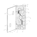
ここで、簡易型防音パネル装置対応の防音強制換気装置3の構成について説明する。
図において、符号4、4は、表裏面となる一対の方形状板体を示す。該方形状板体4、4は、所定の平行間隔、すなわち前述した簡易型防音パネル1の厚みにほぼ等しい間隔行こう覚かんかくをあけて配置され、側面側の端面には連結板体5・・・が接続されて、内部に略平板状をなす密閉空間6が設けられ、これにより簡易型防音パネル1の形状にほぼ等しい形状の遮音パネル7が形成される。
Here, the structure of the soundproof forced ventilation apparatus 3 corresponding to a simple soundproof panel apparatus is demonstrated.
In the figure, reference numerals 4 and 4 denote a pair of rectangular plates that are front and back surfaces. The rectangular plates 4, 4 are arranged with a predetermined parallel interval, that is, with an interval substantially equal to the thickness of the simplified soundproof panel 1 described above, and are connected to the connecting plate 5. .. Are connected to each other, and a sealed space 6 having a substantially flat plate shape is provided therein, whereby a sound insulation panel 7 having a shape substantially equal to the shape of the simplified sound insulation panel 1 is formed.
ここで、方形状板体4の材質については何ら限定されず、金属製であっても、木製であっても合成樹脂製であっても構わないが、騒音を確実に遮音できる材質の方形状板体4でなければならない。 Here, the material of the rectangular plate 4 is not limited at all, and it may be made of metal, wooden, or synthetic resin, but the rectangular shape of the material that can reliably block noise. It must be a plate 4.
そして、前記一対の方形状板体4、4には、通風用開口8,8が各々対向しない箇所に設けられる。
The pair of rectangular plates 4 and 4 are provided at locations where
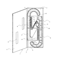
また、前記密閉空間6内には前記通風用開口8、8と連通し、前記略平板状をなす密閉空間6の空間長手方向へ向かい延出配置された吸音路9が設けられる。
In the sealed space 6, there is provided a
この吸音路9内には、例えば吸音材、目詰まり防止フィルムなどで構成された吸音材10が取り付けられていると共に該吸音路9は意識的に曲がりくねった曲線とされ、これにより後述する高効率の吸音、減音効果を有する吸音路9とされる。
A
すなわち、まず、1つ目の要素としては、直進する音を前記曲がりくねった曲線状の吸音路9が作り出す複数回の方向変更により音がぶつかって減音されること、2つ目の要素は、前記曲がりくねった曲線状の吸音路9が作り出す路の長さがもたらす距離減衰によって減音されること、3つ目の要素は、当該吸音路9内面に貼られる吸音材10による吸音の減音効果である。
That is, first, as the first element, the sound is bumped and reduced by a plurality of direction changes created by the curved
また、吸音路9は、換気機能を損なわないよう十分な空気の移動を可能とする容積及び流線が確保されるよう構成することが大切である。
In addition, it is important that the
次に前記吸音路9の作成についてであるが、前記密閉空間6内において仕切り板11を用いて吸音路9を形成すべく仕切り、これにより流路を形成してもよく、また、たとえば楕円形・円形・角パイプ等を用い、これらを緩やかな曲がりくねった曲線状をなす流路に加工して吸音路9としても構わないものである。
Next, regarding the creation of the
また、本発明は簡易型防音パネル1・・・に囲まれる騒音音源に対して、前記通風用開口8によって吸気目的で外側に吸気口を設置することも、排気目的で内側に排気口を設置することもできる。すなわち、同一仕様の通風用開口8を吸気口あるいは排気口として使い分けることができるのである。
In the present invention, the noise source surrounded by the simple soundproof panel 1... Can be installed outside by the
使用方法としては、吸気口を設けた簡易型防音パネル1及び排気口を設けた簡易型防音パネル1を対向させ、一組にして使用することが基本であるが、換気量が少なくてよい場合は、片側にのみ通風用開口8(吸気口あるいは排気口)を設けたものを使用することも可能である。 As a usage method, it is basic to use the simple type soundproof panel 1 provided with the intake port and the simple type soundproof panel 1 provided with the exhaust port so as to face each other. It is also possible to use one provided with a ventilation opening 8 (intake port or exhaust port) only on one side.
しかし、簡易型防音パネル装置2で囲まれる騒音音源には、エンジン式発電機やエンジン式コンプレッサー等の排気ガス及び高熱を発生させ、当該内燃機の作動に必要な空気の供給が必要なものが含まれる。その場合には、通風用開口8(吸気口)を設けた簡易型防音パネル1及び通風用開口8(排気口)を設けた簡易型防音パネル1を対向させ、一組にして使用することになる。 However, the noise sound source surrounded by the simple soundproof panel device 2 includes an engine generator, an engine compressor, or the like that generates exhaust gas and high heat and requires supply of air necessary for the operation of the internal combustion engine. It is. In that case, the simplified soundproof panel 1 provided with the ventilation opening 8 (intake port) and the simplified soundproof panel 1 provided with the ventilation opening 8 (exhaust port) are opposed to each other. Become.
また、簡易型防音パネル装置2で囲まれる騒音音源には、建築工事等での杭頭処理などに代表されるハツリ作業等の巨大騒音と粉塵を発生させるものもが含まれる。したがって、この場合にも通風用開口8(吸気口)を設けた簡易型防音パネル1及び通風用開口8(排気口)を設けた簡易型防音パネル1を対向させ、一組にして使用すると共に、後述する強制ファン12により強制的な換気が出来る様に構成される。 Further, the noise sound source surrounded by the simple soundproof panel device 2 includes a sound source that generates huge noise and dust such as a chiseling work represented by a pile head processing in a building work or the like. Therefore, in this case as well, the simplified soundproof panel 1 provided with the ventilation opening 8 (intake port) and the simplified soundproof panel 1 provided with the ventilation opening 8 (exhaust port) are opposed to each other and used as a set. The forced fan 12 which will be described later is configured to perform forced ventilation.
すなわち、騒音源からの騒音を吸音・遮音・減衰させるのみならず、騒音源(内燃機関などの動力源)から出される排気ガス等換気不足によるエンジントラブルを無くし、且つ、粉塵発生作業等の換気環境を向上させる必要があるからである。また、簡易型防音パネル1とほぼ同等の厚さ内及び大きさ内に設置できるため、例えば内部あるいは外部に突出して設置される外付けの換気装置(ファン・風管)等の様に作業スペースや通路を塞ぐこともなくなる。 In other words, it not only absorbs, insulates and attenuates noise from noise sources, but also eliminates engine problems due to insufficient ventilation such as exhaust gas emitted from noise sources (power sources such as internal combustion engines), and ventilation such as dust generation work This is because the environment needs to be improved. In addition, since it can be installed within the same thickness and size as the simplified soundproof panel 1, the work space such as an external ventilation device (fan or wind pipe) installed protruding inside or outside, for example. And will not block passages.
ここで、強制ファン12は、電力を動力源としたモーターと、該モーターにより空気を強制的に流動させる部材などで構成されたファンとにより形成され、前記通風用開口8(吸気口)に接して吸音路9内に設置される。
Here, the forced fan 12 is formed by a motor using electric power as a power source and a fan configured by a member that forcibly flows air by the motor, and is in contact with the ventilation opening 8 (intake port). Installed in the
なお、前記例えばモーターを作動させる電力の種類には何ら制限はなく、一般の商用電源をコンセントなどから供用しても構わないし、充電池や乾電池などにより電力を受給しても構わない。 The type of electric power for operating the motor is not limited, for example, and a general commercial power source may be used from an outlet or the like, or electric power may be received by a rechargeable battery or a dry battery.
また、図において、符号13は、作動スイッチ、電源プラグなどが納められた設置ボックスである。
In the figure,
なお、防音強制換気装置3内に組み込まれる強制ファン12や通風用開口8(吸気口や排気口)は、決して単数である必要はなく複数個で構成しても構わないものである。 In addition, the forced fan 12 and the ventilation opening 8 (intake port and exhaust port) incorporated in the soundproof forced ventilation device 3 do not have to be singular and may be configured by a plurality.
しかして、簡易型防音パネル装置2で囲まれた騒音源から出た防音の対象になる音を含む排気は、前記吸気口から強制ファン12の働きによって吸音路9内に取り込まれ、該吸音路9内を通過する際、吸音路9の作り出す流体方向変換による遮蔽音効果をあげながら進み、通常の状態でパネル厚さを通過する流線の何倍もの音の距離減衰を経ながら、吸音路9内部に貼り付けられた吸音材10にもぶつかりながら進み、最終的に通風用開口8(排気口)から外部に送り出される。
Thus, the exhaust gas including the sound to be soundproofed from the noise source surrounded by the simple soundproof panel device 2 is taken into the
よって、組み立てられた簡易型防音パネル装置2の中にある騒音音源から、空気流入口(通風用開口8:吸気口)に向かって流れ出る音エネルギーは、内部に設置された吸音材10及び流路の方向変換や流路の距離減衰により消耗され、減音され、大きな防音効果がもたらされるのである。
Therefore, the sound energy flowing out from the noise source in the assembled simplified soundproof panel device 2 toward the air inlet (ventilation opening 8: intake port) is the
1 簡易型防音パネル
2 簡易型防音パネル装置
3 防音強制換気装置
4 方形状板体
5 連結板体
6 密閉空間
7 遮音パネル
8 通風用開口
9 吸音路
10 吸音材
11 仕切り板
12 強制ファン
13 設置ボックス
DESCRIPTION OF SYMBOLS 1 Simple type soundproof panel 2 Simple type soundproof panel device 3 Soundproof forced ventilation device 4 Rectangular plate body 5 Connection plate body 6 Sealed space 7
Claims (2)
前記一対の方形状板体には、通風用開口が各々設けられ、前記密閉空間内には前記通風用開口と連通し、前記略平板状をなす密閉空間の空間長手方向へ向かい延出配置された吸音路が設けられ、
前記吸音路内には吸音材が取り付けられると共に該吸音路が曲線とされて高効率吸音路とされ、かつ該吸音路には前記通風用開口に接して電力を動力源とした強制ファンが取り付けられて強制通風可能とされた、
ことを特徴とする簡易型防音パネル装置対応防音強制換気装置
A pair of rectangular plates that are front and back surfaces are arranged at intervals and a side plate is connected to a connecting plate to form a sound insulation panel provided with a substantially flat sealed space inside,
The pair of rectangular plates are each provided with a ventilation opening, communicated with the ventilation opening in the sealed space, and arranged to extend in the longitudinal direction of the substantially flat sealed space. Sound absorption path is provided,
A sound absorbing material is mounted in the sound absorbing path, and the sound absorbing path is curved to form a highly efficient sound absorbing path, and a forced fan that uses electric power as a power source in contact with the ventilation opening is attached to the sound absorbing path. And forced ventilation was possible,
Sound-proof forced ventilation device compatible with simple sound-proof panel device
ことを特徴とした請求項1記載の簡易型防音パネル装置対応防音強制換気装置 A dry battery or a rechargeable battery is used as a power source for the forced fan member.
The soundproof forced ventilation apparatus corresponding to the simple type soundproof panel apparatus according to claim 1
Priority Applications (1)
| Application Number | Priority Date | Filing Date | Title |
|---|---|---|---|
| JP2012240026A JP2014088727A (en) | 2012-10-31 | 2012-10-31 | Soundproof forcible ventilation device corresponding to simple soundproof panel device |
Applications Claiming Priority (1)
| Application Number | Priority Date | Filing Date | Title |
|---|---|---|---|
| JP2012240026A JP2014088727A (en) | 2012-10-31 | 2012-10-31 | Soundproof forcible ventilation device corresponding to simple soundproof panel device |
Publications (1)
| Publication Number | Publication Date |
|---|---|
| JP2014088727A true JP2014088727A (en) | 2014-05-15 |
Family
ID=50790826
Family Applications (1)
| Application Number | Title | Priority Date | Filing Date |
|---|---|---|---|
| JP2012240026A Pending JP2014088727A (en) | 2012-10-31 | 2012-10-31 | Soundproof forcible ventilation device corresponding to simple soundproof panel device |
Country Status (1)
| Country | Link |
|---|---|
| JP (1) | JP2014088727A (en) |
Cited By (2)
| Publication number | Priority date | Publication date | Assignee | Title |
|---|---|---|---|---|
| DE102015106211A1 (en) | 2014-04-23 | 2015-10-29 | Denso Corporation | Rotating electrical machine suitable for detecting a malfunction in a switch |
| CN119162939A (en) * | 2024-10-10 | 2024-12-20 | 中铁大桥局集团第五工程有限公司 | A highway load-reducing sound barrier and load-reducing adjustment method |
Citations (2)
| Publication number | Priority date | Publication date | Assignee | Title |
|---|---|---|---|---|
| JPS60170413U (en) * | 1984-04-20 | 1985-11-12 | 株式会社河合楽器製作所 | Soundproof panel for ventilation ducts |
| JPH10152910A (en) * | 1996-11-25 | 1998-06-09 | Fujita Corp | Sound insulation panel unit |
-
2012
- 2012-10-31 JP JP2012240026A patent/JP2014088727A/en active Pending
Patent Citations (2)
| Publication number | Priority date | Publication date | Assignee | Title |
|---|---|---|---|---|
| JPS60170413U (en) * | 1984-04-20 | 1985-11-12 | 株式会社河合楽器製作所 | Soundproof panel for ventilation ducts |
| JPH10152910A (en) * | 1996-11-25 | 1998-06-09 | Fujita Corp | Sound insulation panel unit |
Cited By (2)
| Publication number | Priority date | Publication date | Assignee | Title |
|---|---|---|---|---|
| DE102015106211A1 (en) | 2014-04-23 | 2015-10-29 | Denso Corporation | Rotating electrical machine suitable for detecting a malfunction in a switch |
| CN119162939A (en) * | 2024-10-10 | 2024-12-20 | 中铁大桥局集团第五工程有限公司 | A highway load-reducing sound barrier and load-reducing adjustment method |
Similar Documents
| Publication | Publication Date | Title |
|---|---|---|
| CN106956587B (en) | Vehicle power compartment and engineering vehicle with same | |
| CN101660353B (en) | Noise reduction chamber | |
| CN107399419B (en) | Ocean engineering living cabin and noise elimination ventilation device thereof | |
| CN103711338B (en) | A kind of super-silent diesel generating set machine room noise control method | |
| CN206190400U (en) | Hush air wind cooling type internal combustion engine generating set | |
| CN109027528B (en) | Unit assembly platform | |
| JP2014088727A (en) | Soundproof forcible ventilation device corresponding to simple soundproof panel device | |
| CN202444369U (en) | Motor silencer | |
| CN204458025U (en) | A special generator set with independent air duct, cooling and sound | |
| CN215367923U (en) | Sound insulation system module | |
| CN105508044A (en) | Low-noise power station chamber | |
| CN203272060U (en) | Double-layer sound attenuation blimp for natural gas compressor | |
| JP4203381B2 (en) | Soundproof engine driven work machine | |
| CN204512001U (en) | A kind of blower fan sound-insulating cover | |
| CN204456985U (en) | A Noise Reduction Generator Room for Combined Cooling, Heating and Power Supply System | |
| CN205140510U (en) | Exhaust muffler with adjustable air input | |
| CN203420768U (en) | Noise abatement device of electric generator | |
| CN203756337U (en) | Muting box of diesel generator | |
| CN108979851B (en) | Generating device and unit installation mechanism | |
| CN203716542U (en) | Diesel generating set machine room | |
| CN203067095U (en) | Diesel generating set sound insulation outer cover | |
| CN202691457U (en) | Muting box of gas turbine set | |
| CN223514122U (en) | Noise reduction assembly of power exchange station and power exchange station | |
| CN209744635U (en) | Underground power generation chamber with noise reduction and ventilation functions | |
| CN209802129U (en) | Cooling tower with silencer |
Legal Events
| Date | Code | Title | Description |
|---|---|---|---|
| A621 | Written request for application examination |
Free format text: JAPANESE INTERMEDIATE CODE: A621 Effective date: 20151006 |
|
| A977 | Report on retrieval |
Free format text: JAPANESE INTERMEDIATE CODE: A971007 Effective date: 20160810 |
|
| A131 | Notification of reasons for refusal |
Free format text: JAPANESE INTERMEDIATE CODE: A131 Effective date: 20160816 |
|
| A02 | Decision of refusal |
Free format text: JAPANESE INTERMEDIATE CODE: A02 Effective date: 20170224 |