JP2014088715A - End frame - Google Patents

End frame

Info

Publication number
JP2014088715A
JP2014088715A JP2012239655A JP2012239655A JP2014088715A JP 2014088715 A JP2014088715 A JP 2014088715A JP 2012239655 A JP2012239655 A JP 2012239655A JP 2012239655 A JP2012239655 A JP 2012239655A JP 2014088715 A JP2014088715 A JP 2014088715A
Authority
JP
Japan
Prior art keywords
frame
vertical cover
vertical
indoor side
attached
Prior art date
Legal status (The legal status is an assumption and is not a legal conclusion. Google has not performed a legal analysis and makes no representation as to the accuracy of the status listed.)
Granted
Application number
JP2012239655A
Other languages
Japanese (ja)
Other versions
JP6031326B2 (en
Inventor
Satoshi Yanai
智 谷内
Mitsutaka Saito
充孝 斉藤
Current Assignee (The listed assignees may be inaccurate. Google has not performed a legal analysis and makes no representation or warranty as to the accuracy of the list.)
Sankyo Tateyama Inc
Original Assignee
Sankyo Tateyama Inc
Priority date (The priority date is an assumption and is not a legal conclusion. Google has not performed a legal analysis and makes no representation as to the accuracy of the date listed.)
Filing date
Publication date
Application filed by Sankyo Tateyama Inc filed Critical Sankyo Tateyama Inc
Priority to JP2012239655A priority Critical patent/JP6031326B2/en
Publication of JP2014088715A publication Critical patent/JP2014088715A/en
Application granted granted Critical
Publication of JP6031326B2 publication Critical patent/JP6031326B2/en
Active legal-status Critical Current
Anticipated expiration legal-status Critical

Links

Images

Landscapes

  • Door And Window Frames Mounted To Openings (AREA)

Abstract

PROBLEM TO BE SOLVED: To provide an end frame which is attached on the indoor side surface of a marginal part of a skeleton opening and has excellent design.SOLUTION: An end frame includes a vertical extended frame, a vertical cover member, and a header cap. The vertical extended frame has a fitted part and is attached on the indoor side surface of a marginal part of a skeleton opening. The vertical cover member is used for covering the vertical extended frame, and has an indoor side width face part, a fitting part provided on the outdoor side of the indoor side width face part, and a fixed part provided on the outdoor side of the end in the longitudinal direction of the indoor side width face part. The vertical cover member is provided at a position where the fixed part avoids the fitting part and attached by fitting the fitting part to the fitted part of the vertical extended frame from the indoor side. The header cap has a fixing part and a flat depth face; and is fixed by engaging the fixing part with the fixed part of the vertical cover member.

Description

本発明は、既設の窓の室内側に内窓を取り付ける際などに、躯体開口部の縁部の室内側面に取り付ける見切枠に関する。   The present invention relates to a parting frame attached to an indoor side surface of an edge portion of a housing opening when an inner window is attached to the indoor side of an existing window.

近年、既設の窓の内側に取り付けて断熱性や防音性を向上させる内窓が広く普及している。こうした内窓は、既設窓の室内側に設けられた額縁の見込面に取り付けるものであるが、額縁の見込面の見込幅が短い場合、そのままでは内窓を取り付けることができない。その場合、額縁の室内側にふかし枠を取り付けて見込面を延長し、額縁とふかし枠に跨って内窓を取り付ける。一般に、ふかし枠はアルミ形材からなるものであって、その室内側に樹脂製のカバー材を取り付けてある。より詳しくは、非特許文献1に示すように、縦ふかし枠と横ふかし枠にそれぞれ縦カバー材と横カバー材を取り付けてあり、角部には、縦カバー材と横カバー材の両方の端部を覆うようにして、略矩形のキャップを室内側から取り付けてあった。   In recent years, inner windows that are installed inside existing windows to improve heat insulation and soundproofing have become widespread. Such an inner window is attached to the expected surface of the frame provided on the indoor side of the existing window. However, if the expected width of the expected surface of the frame is short, the inner window cannot be attached as it is. In that case, a cover frame is attached to the indoor side of the frame to extend the expected surface, and an inner window is mounted across the frame and the cover frame. In general, the pruning frame is made of an aluminum shape, and a resin cover material is attached to the indoor side. More specifically, as shown in Non-Patent Document 1, a vertical cover material and a horizontal cover material are attached to a vertical cover frame and a horizontal cover frame, respectively. A substantially rectangular cap was attached from the indoor side so as to cover the part.

「リフォーム商品総合カタログ2012−2013」、三協立山株式会社、平成24年6月、p.616“Renovation Product General Catalog 2012-2013”, Sankyo Tateyama Co., Ltd., June 2012, p. 616

しかしながら、このような構成の従来品は、室内側から角部の大きなキャップが目立ってしまい、意匠性が好ましいものではなかった。   However, the conventional product having such a configuration has a large corner portion conspicuous from the indoor side and is not preferable in design.

本発明は、上記事情を鑑みたものであり、躯体開口部の縁部の室内側面に取り付けるものであって、意匠性が良好な見切枠を提供することを目的とする。   The present invention has been made in view of the above circumstances, and is intended to provide a parting frame having a good design property, which is attached to the indoor side surface of the edge of the housing opening.

本発明のうち請求項1の発明は、縦ふかし枠と、縦カバー材と、小口キャップとを備え、縦ふかし枠は、被嵌合部を有し、躯体開口部の縁部の室内側面に取り付けてあり、縦カバー材は、縦ふかし枠をカバーするものであり、室内側見付面部と、室内側見付面部の室外側に設けた嵌合部と、室内側見付面部の長手方向端部の室外側に設けた被固定部を有し、被固定部が嵌合部を回避する位置に設けてあって、嵌合部を縦ふかし枠の被嵌合部に室内側から嵌合させて取り付けてあり、小口キャップは、固定部と、平坦な見込面部を有し、固定部を縦カバー材の被固定部に係合させて固定してあることを特徴とする。   According to the first aspect of the present invention, the vertical cover frame includes a vertical cover frame, a vertical cover member, and a small cap, and the vertical cover frame has a fitted portion and is provided on the indoor side surface of the edge portion of the housing opening. The vertical cover material covers the vertical watermark frame. The indoor side finding surface part, the fitting part provided on the outdoor side of the indoor side finding surface part, and the longitudinal direction of the indoor side finding surface part It has a fixed part provided on the outdoor side of the end, and the fixed part is provided at a position that avoids the fitting part, and the fitting part is fitted to the fitting part of the vertical cover frame from the indoor side. The small cap has a fixed portion and a flat prospect surface portion, and is fixed by engaging the fixed portion with the fixed portion of the vertical cover material.

本発明のうち請求項2の発明は、縦ふかし枠と、縦カバー材と、小口キャップとを備え、縦ふかし枠は、躯体開口部の縁部の室内側面に取り付けてあり、縦カバー材は、縦ふかし枠をカバーするものであり、縦ふかし枠に室内側から取り付けてあって、室内側見付面部と外周側見込面部を備えたカバー部を有するとともに、カバー部の内側に中空部を有しており、小口キャップは、挿入突部と、挟持突部とを有しており、挿入突部を縦カバー材の中空部に挿入し、挿入突部と挟持突部で中空部の壁面を挟み込んで固定してあることを特徴とする。   The invention of claim 2 of the present invention comprises a vertical cover frame, a vertical cover material, and a small cap, and the vertical cover frame is attached to the indoor side surface of the edge portion of the housing opening. The vertical cover frame is covered, and is attached to the vertical cover frame from the indoor side, and has a cover portion with an indoor side finding surface portion and an outer peripheral side looking surface portion, and a hollow portion is provided inside the cover portion. The small cap has an insertion protrusion and a sandwiching protrusion, and the insertion protrusion is inserted into the hollow portion of the vertical cover material, and the wall surface of the hollow portion is formed by the insertion protrusion and the sandwiching protrusion. It is characterized by sandwiching and fixing.

本発明のうち請求項1の発明によれば、カバー材のキャップが縦カバー材の小口に取り付けられており、さらに小口キャップの見込面部が平坦になっていることから、小口キャップが室内側にほとんど露出せず目立たないので、意匠性が良好である。そして小口キャップが上下に突出しないので、躯体開口部に近接して他の構造物が設けられている場合でも、それと干渉することなく取り付けることができる。また、小口キャップを縦カバー材に取り付けるための被固定部が、室内側見付面部の室外側に設けてあり、固定部及び被固定部が室内側見付面部に隠されて室内側から見えないので、この点においても意匠性が良好である。   According to the first aspect of the present invention, since the cap of the cover material is attached to the small edge of the vertical cover material and the expected surface portion of the small edge cap is flat, the small edge cap is located on the indoor side. Since it is hardly exposed and not conspicuous, the design is good. And since a fore edge cap does not protrude up and down, even when another structure is provided close to the housing opening, it can be attached without interfering with it. In addition, a fixed part for attaching the fore edge cap to the vertical cover member is provided on the outdoor side of the indoor side finding surface part, and the fixed part and the fixed part are hidden by the indoor side finding surface part and visible from the indoor side. Therefore, the design is good also in this respect.

本発明のうち請求項2の発明によれば、カバー材のキャップが縦カバー材の小口に取り付けられていて室内側にほとんど露出せず目立たないので、意匠性が良好である。また、小口キャップを縦カバー材に取り付けるための突部が縦カバー材の内側に納まって室内側から見えないので、この点においても意匠性が良好である。   According to the invention of the second aspect of the present invention, the cap of the cover material is attached to the small edge of the vertical cover material and is hardly exposed to the indoor side and is not noticeable. Moreover, since the protrusion for attaching the fore edge cap to the vertical cover material is housed inside the vertical cover material and cannot be seen from the indoor side, the design is also good in this respect.

第一実施形態の左側部分の拡大図である。It is an enlarged view of the left side part of 1st embodiment. 第一実施形態の上側部分の拡大図である。It is an enlarged view of the upper part of a first embodiment. 第一実施形態の下側部分の拡大図である。It is an enlarged view of the lower part of a first embodiment. 第一実施形態の横断面図である。It is a cross-sectional view of the first embodiment. 第一実施形態の縦断面図である。It is a longitudinal cross-sectional view of 1st embodiment. 第一実施形態の小口キャップの五面図及び縦カバー材への取り付けの説明図である。It is explanatory drawing of the 5th page figure of the small cap of 1st embodiment, and the attachment to a vertical cover material. 縦カバー材と横カバー材の納まりの説明図である。It is explanatory drawing of the accommodation of a vertical cover material and a horizontal cover material. 第二実施形態の下側部分の拡大図である。It is an enlarged view of the lower part of 2nd embodiment. 第三実施形態の左側部分の拡大図である。It is an enlarged view of the left side part of 3rd embodiment. 第三実施形態の下側部分の拡大図である。It is an enlarged view of the lower part of 3rd embodiment. 床面キャップの五面図及び縦カバー材への取り付けの説明図である。It is explanatory drawing of the 5th view of a floor cap and attachment to a vertical cover material. 第四実施形態の左側部分の拡大図である。It is an enlarged view of the left side part of 4th embodiment. 第四実施形態の上側部分の拡大図である。It is an enlarged view of the upper part of a fourth embodiment. 第四実施形態の下側部分の拡大図である。It is an enlarged view of the lower part of 4th embodiment. 第四実施形態の横断面図である。It is a cross-sectional view of a fourth embodiment. 第四実施形態の縦断面図である。It is a longitudinal cross-sectional view of 4th embodiment. 第四実施形態の小口キャップの五面図及び縦カバー材への取り付けの説明図である。It is explanatory drawing of the 5th page figure of the small cap of 4th embodiment, and the attachment to a vertical cover material. 第五実施形態の左側部分の拡大図である。It is an enlarged view of the left side part of 5th embodiment. 第五実施形態の上側部分の拡大図である。It is an enlarged view of the upper part of 5th embodiment. 第五実施形態の下側部分の拡大図である。It is an enlarged view of the lower part of 5th embodiment. 第六実施形態の下側部分の拡大図である。It is an enlarged view of the lower part of 6th embodiment.

以下、本発明の実施の形態を図面に基づいて説明する。なお、以下において左右とは、本発明の見切枠を室内側から正面視した場合の左右方向を示すものとする。また、本発明の見切枠には、左右の縦枠と上下の横枠を四周枠組みした四方枠と、左右の縦枠と上側の横枠を枠組みした三方枠の両方を含む。三方枠の場合、左右の縦枠の下端が窓の額縁や床面などに突き当たることになる。そして、以下の各実施形態は、何れも、躯体開口部Sを有する躯体の室内側壁面Wに対して、断熱性を高めるためのリフォーム工事を行うことを想定したものである。   Hereinafter, embodiments of the present invention will be described with reference to the drawings. In the following description, “left and right” refers to the left and right direction when the parting frame of the present invention is viewed from the indoor side. Further, the parting frame of the present invention includes both a four-sided frame in which the left and right vertical frames and the upper and lower horizontal frames are framed in four directions, and a three-way frame in which the left and right vertical frames and the upper horizontal frame are framed. In the case of a three-sided frame, the lower ends of the left and right vertical frames come into contact with the frame of the window or the floor surface. And each following embodiment assumes performing the renovation construction for improving heat insulation with respect to the indoor side wall surface W of the housing which has the housing opening S.

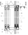
まず、見切枠の第一実施形態について、図1〜図7に基づき説明する。見切枠の第一実施形態は、左右の縦ふかし枠1、縦カバー材2及び小口キャップ3と、上下の横ふかし枠4及び横カバー材5とを備える四方枠形状のものである。見切枠を取り付ける躯体開口部Sには、窓(既設窓100)が設けられている。既設窓100は、図4及び図5に示すように、四周枠組みした窓枠101と、窓枠101に引違いに納めた二枚の障子102a,102bからなる引違い窓であって、躯体開口部Sの室外側端に取り付けられている。また、既設窓100の上下左右の窓枠101の室内側には、躯体開口部Sの見込面を覆う矩形板状の額縁200が取り付けられている。額縁200の室内側端は、躯体の室内側壁面Wよりも室内側に突出している。   First, a first embodiment of a parting frame will be described with reference to FIGS. The first embodiment of the parting frame has a four-sided frame shape including left and right vertical watermark frames 1, vertical cover material 2 and fore edge cap 3, and upper and lower horizontal watermark frames 4 and horizontal cover material 5. A window (existing window 100) is provided in the housing opening S to which the parting frame is attached. As shown in FIGS. 4 and 5, the existing window 100 is a sliding window composed of a window frame 101 having a four-round frame and two shojis 102 a and 102 b placed in the window frame 101. It is attached to the outdoor end of the part S. A rectangular plate-shaped frame 200 that covers the expected surface of the housing opening S is attached to the indoor side of the upper, lower, left, and right window frames 101 of the existing window 100. The indoor side end of the frame 200 protrudes more indoors than the indoor side wall surface W of the housing.

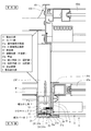
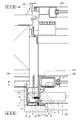
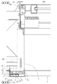
さらに、額縁200の室内側面には、見切材が取り付けられている。左右(縦)の額縁200に取り付けられた見切材は、図1に示すように、縦ふかし枠1と、縦カバー材2からなるものである。なお、図1は見切枠の左側部分を示すものであるが、右側部分はこれと左右対称な構造である。縦ふかし枠1は、断面が室内外方向に長い略矩形で中空のアルミ形材からなるものであり、左右方向幅が額縁200と同じであって、額縁200の室内側面にネジ止めして取り付けてある。すなわち、縦ふかし枠1を取り付けることで、額縁200が室内側に延長された形になっている。縦ふかし枠1の室内側面には、長手方向(上下方向)に延びる溝部を形成してあり、これが縦カバー材2を取り付けるための被嵌合部11となる。そして、左右の額縁200の内周側面と、縦ふかし枠1の内周側面とに跨って樹脂板からなる被覆材6を取り付けてある。被覆材6により、額縁200と縦ふかし枠1の境目が覆われ、左右の内周側面が完全な面一となっている。なお、被覆材6の外周側面には、長手方向に平行な溝が等間隔に多数形成されており、この溝で被覆材6を折り取って容易に長さ調整できるようになっている。また、折り取るのではなくて、溝にカッターの刃を沿わせて切り取ってもよく、その場合、ジグなどを用いることなく正確に直線切断でき、折り取る場合に比べてより切断面を平滑にできるので意匠性が向上する。   Further, a parting material is attached to the indoor side surface of the frame 200. The parting material attached to the left and right (vertical) picture frames 200 is composed of a vertical cover frame 1 and a vertical cover material 2 as shown in FIG. FIG. 1 shows the left part of the parting frame, but the right part has a symmetrical structure. The vertical pruning frame 1 is made of a substantially rectangular and hollow aluminum section whose section is long in the indoor / outdoor direction, and the width in the left / right direction is the same as that of the frame 200, and is attached by screwing to the indoor side surface of the frame 200. It is. That is, the frame 200 is extended to the indoor side by attaching the vertical cover frame 1. A groove portion extending in the longitudinal direction (vertical direction) is formed on the indoor side surface of the vertical cover frame 1, and this is a fitted portion 11 for attaching the vertical cover material 2. And the coating | covering material 6 which consists of a resin board is attached ranging over the inner peripheral side surface of the right-and-left frame 200 and the inner peripheral side surface of the vertical cover frame 1. The covering material 6 covers the boundary between the frame 200 and the vertical cover frame 1, and the left and right inner peripheral side surfaces are completely flush with each other. A large number of grooves parallel to the longitudinal direction are formed at equal intervals on the outer peripheral side surface of the covering material 6, and the length of the covering material 6 can be easily adjusted by breaking the covering material 6 with these grooves. In addition, instead of folding, the cutter blade may be cut along the groove, and in that case, it can be cut straight without using a jig, etc., and the cutting surface is smoother than when folding. As a result, the design is improved.

縦カバー材2は、硬質の樹脂製で、左右に延びる室内側見付面部21aと、室内側見付面部21aの外周側端から室外側に延びる外周側見込面部21bからなる略L字形のカバー部21を有し、カバー部21の内側(室内側見付面部21aの室外側かつ外周側見込面部21bの内周側)に、矩形の中空部23を形成してある。この中空部23は、小口キャップ3を固定するための被固定部となる。また中空部23は、左右方向幅が、額縁200と被覆材6を合わせた厚さと等しくなっている。そして、中空部23の室外側の壁面23aには、室外側に突出する二つの爪部が形成されており、これが縦ふかし枠1の被嵌合部11に嵌合する嵌合部22となっている。嵌合部22を縦ふかし枠1の被嵌合部11に嵌合させると、室内側見付面部21aと外周側見込面部21bが、それぞれ縦ふかし枠1の室内側面と外周側面を覆う。そして、外周側見込面部21bが縦ふかし枠1の外周側面に当接し、中空部23の内周側面が被覆材6の内周側面と面一になる。また、室内側見付面部21aは、中空部23の内周側面よりもさらに内周側に延びており、その先端の室外側面には、軟質の樹脂からなるシール部24を設けてある。シール部24は、縦カバー材2のその他の部分と一体に成型したものである。そして、外周側見込面部21bは、縦ふかし枠1の室外側端よりもさらに室外側に延びており、額縁200の外周側面にも当接している。   The vertical cover member 2 is made of a hard resin, and includes a substantially L-shaped cover including an indoor side finding surface portion 21a extending in the left and right directions and an outer peripheral side facing surface portion 21b extending outward from the outer peripheral side end of the indoor side finding surface portion 21a. A rectangular hollow portion 23 is formed on the inner side of the cover portion 21 (outside of the indoor-side finding surface portion 21a and on the inner peripheral side of the outer-side expected surface portion 21b). The hollow portion 23 serves as a fixed portion for fixing the fore edge cap 3. Further, the hollow portion 23 has a width in the left-right direction that is equal to the combined thickness of the frame 200 and the covering material 6. The outer wall surface 23 a of the hollow portion 23 is formed with two claw portions projecting to the outdoor side, and this becomes the fitting portion 22 to be fitted to the fitted portion 11 of the vertical cover frame 1. ing. When the fitting portion 22 is fitted to the fitted portion 11 of the vertical cover frame 1, the indoor side finding surface portion 21 a and the outer peripheral side looking surface portion 21 b cover the indoor side surface and the outer peripheral side surface of the vertical cover frame 1, respectively. Then, the outer peripheral side expected surface portion 21 b abuts on the outer peripheral side surface of the vertical cover frame 1, and the inner peripheral side surface of the hollow portion 23 is flush with the inner peripheral side surface of the covering material 6. Further, the indoor-side finding surface portion 21a extends further to the inner peripheral side than the inner peripheral side surface of the hollow portion 23, and a seal portion 24 made of a soft resin is provided on the outdoor side surface at the tip. The seal portion 24 is molded integrally with the other portions of the vertical cover material 2. Further, the outer peripheral side expected surface portion 21 b extends further to the outdoor side than the outdoor outer end of the vertical cover frame 1, and is in contact with the outer peripheral side surface of the frame 200.

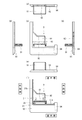
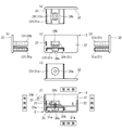
小口キャップ3は、硬質の樹脂製で、図6((a)〜(e)が五面図、(f)が縦カバー材2に取り付けた状態の説明図)に示すように、略矩形で平板状の見込面部32と、見込面部32の内周側面に形成した固定部31及び突条33からなる。固定部31は、見込面部32の室内側かつ外周側の角部に形成した挿入突部31aと、挿入突部31aの室外側に形成した挟持突部31bからなる。挿入突部31aは、縦カバー材2の中空部23にちょうど嵌まる形状となっている。そして、挿入突部31a及び挟持突部31bには、室内外方向に貫通するネジ孔34a,34bを形成してある。また、突条33は、室内外に延びるもので、挿入突部31aの外周側端の室外側に形成してある。このように形成した小口キャップ3は、縦カバー材2の上下の端部に固定される。より詳しくは、小口キャップ3の挿入突部31aを縦カバー材2の中空部23に挿入する。すると、中空部23の室外側の壁面23aは挿入突部31aと挟持突部31bに挟まれ、挟持突部31bは、嵌合部22を構成する二本の爪部の間に納まる。すなわち、縦カバー材2の中空部(被固定部)23が嵌合部22を回避している。また、突条33は、縦カバー材2の外周側見込面部21bの内周側面に当接して、ガタツキを防ぐ。そして、挟持突部31bのネジ孔34bの室外側から、ネジ35を挿入してねじ込む。縦カバー材2の中空部23の壁面23aにはネジ孔が形成されていないが、このネジ35はタッピングネジであり、ねじ込むことで壁面23aに孔を開けて、小口キャップ3が縦カバー材2に固定される。ネジ35の先端は、挿入突部31aのネジ孔34a内に納まり、外側に露出することはない。また、挿入突部31aの室内外方向の厚さが薄く、ネジ35の先端がネジ孔34aから突出したとしても、ネジ35の先端は中空部23内に納まって外側に露出しない。なお、図6に示したものは、左側の縦カバー材2の下端及び右側の縦カバー材2の上端に取り付けるものであり、左側の縦カバー材2の上端及び右側の縦カバー材2の下端に取り付けるものは、これと左右対称な形状となる。   As shown in FIG. 6 ((a) to (e) is a five-sided view, and (f) is an explanatory view of a state where it is attached to the vertical cover member 2), the forehead cap 3 is made of a hard resin. It consists of a flat prospecting surface part 32 and a fixing part 31 and a protrusion 33 formed on the inner peripheral side surface of the prospective surface part 32. The fixing portion 31 includes an insertion protrusion 31a formed at a corner on the indoor side and the outer periphery of the prospective surface portion 32, and a sandwiching protrusion 31b formed on the outdoor side of the insertion protrusion 31a. The insertion protrusion 31 a has a shape that fits into the hollow portion 23 of the vertical cover member 2. The insertion protrusion 31a and the holding protrusion 31b are formed with screw holes 34a and 34b penetrating in the indoor / outdoor direction. Further, the protrusion 33 extends outside the room and is formed on the outdoor side of the outer peripheral side end of the insertion protrusion 31a. The small cap 3 formed in this way is fixed to the upper and lower ends of the vertical cover member 2. More specifically, the insertion protrusion 31 a of the fore edge cap 3 is inserted into the hollow portion 23 of the vertical cover member 2. Then, the wall surface 23a on the outdoor side of the hollow portion 23 is sandwiched between the insertion protrusion 31a and the sandwiching protrusion 31b, and the sandwiching protrusion 31b fits between the two claw portions constituting the fitting portion 22. That is, the hollow portion (fixed portion) 23 of the vertical cover member 2 avoids the fitting portion 22. Moreover, the protrusion 33 contacts the inner peripheral side surface of the outer peripheral side expected surface portion 21b of the vertical cover member 2 to prevent rattling. Then, the screw 35 is inserted and screwed in from the outdoor side of the screw hole 34b of the sandwiching protrusion 31b. A screw hole is not formed in the wall surface 23a of the hollow portion 23 of the vertical cover member 2, but this screw 35 is a tapping screw, and a hole is made in the wall surface 23a by screwing, so that the small cap 3 is connected to the vertical cover member 2. Fixed to. The tip of the screw 35 is housed in the screw hole 34a of the insertion protrusion 31a and is not exposed to the outside. Further, even if the insertion protrusion 31a is thin in the indoor / outdoor direction and the tip of the screw 35 protrudes from the screw hole 34a, the tip of the screw 35 is accommodated in the hollow portion 23 and is not exposed to the outside. 6 are attached to the lower end of the left vertical cover member 2 and the upper end of the right vertical cover member 2, and the upper end of the left vertical cover member 2 and the lower end of the right vertical cover member 2 are shown. What is attached to is a symmetrical shape.

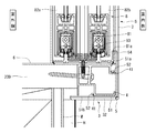
また、上下(横)の額縁200に取り付けられた見切材は、図2及び図3に示すように、横ふかし枠4と、横カバー材5からなるものである。上側の横ふかし枠4は、断面略矩形で中空のアルミ形材からなるものであり、上下方向幅が額縁200と同じであって、額縁200の室内側面にネジ止めして取り付けてある。すなわち、上側の横ふかし枠4を取り付けることで、上側の額縁200が室内側に延長された形になっている。また、下側の横ふかし枠4は、室内側部分が下側に膨らんだ形状で中空のアルミ形材からなるものであって、額縁200の室内側面にネジ止めして取り付けてある。下側の横ふかし枠4は、上下方向幅が額縁200よりも厚いが、内周側面(上側面)が額縁200と面一になっており、額縁200の内周側面(上側面)が室内側に延長された形になっている。そして、上下の横ふかし枠4の室内側面と外周側面には、それぞれ爪部を形成してあり、これが横カバー材を取り付けるための被嵌合部41となっている。そして、上下の額縁200の内周側面と、横ふかし枠4の内周側面とに跨って樹脂板からなる被覆材6を取り付けてある。被覆材6により、額縁200と横ふかし枠4の境目が覆われ、上下の内周側面が完全な面一となっている。   Moreover, the parting material attached to the up-and-down (horizontal) frame 200 consists of the horizontal cover frame 4 and the horizontal cover material 5, as shown in FIG.2 and FIG.3. The upper horizontal frame 4 is made of a hollow aluminum shape having a substantially rectangular cross section, and has the same vertical width as the frame 200 and is screwed to the indoor side surface of the frame 200. That is, the upper frame 200 is extended to the indoor side by attaching the upper horizontal cover frame 4. Further, the lower horizontal cover frame 4 is made of a hollow aluminum shape with the indoor side portion bulging downward, and is screwed to the indoor side surface of the frame 200. The lower horizontal frame 4 is thicker in the vertical direction than the frame 200, but the inner circumferential side (upper side) is flush with the frame 200, and the inner circumferential side (upper side) of the frame 200 is the chamber. The shape is extended inward. And the nail | claw part is formed in the indoor side surface and outer peripheral side surface of the upper and lower horizontal puff frame 4, respectively, and this becomes the to-be-fitted part 41 for attaching a horizontal cover material. And the coating | covering material 6 which consists of a resin board is attached ranging over the inner peripheral side surface of the upper and lower frame 200, and the inner peripheral side surface of the horizontal cover frame 4. As shown in FIG. The covering material 6 covers the boundary between the frame 200 and the horizontal cover frame 4, and the upper and lower inner peripheral side surfaces are completely flush with each other.

横カバー材5は、硬質の樹脂製で、上下に延びる室内側見付面部51aと、室内側見付面部51aの外周側端から室外側に延びる外周側見込面部51bからなる略L字形のカバー部51を有し、カバー部51の内側(室内側見付面部51aの室外側面と、外周側見込面部51bの内周側面)に、爪部を形成してある。この爪部は、横ふかし枠4の被嵌合部41に嵌合する嵌合部52となっている。嵌合部52を横ふかし枠4の被嵌合部41に嵌合させると、室内側見付面部51aと外周側見込面部51bが、それぞれ横ふかし枠4の室内側面と外周側面を覆う。そして、外周側見込面部51bが横ふかし枠4の外周側面に当接する。また、室内側見付面部51aは、被覆材6の内周側面よりもさらに内周側に延びており、その先端の室外側面には、軟質の樹脂からなるシール部54を設けてある。シール部54は、横カバー材5のその他の部分と一体に成型したものである。そして、外周側見込面部51bは、横ふかし枠4の室外側端よりもさらに室外側に延びていて、上側においては額縁200の外周側面にも当接している。一方、下側においては、横ふかし枠4の外周側面が額縁200の外周側面よりも外周側(下側)に位置しているので、外周側見込面部51bと額縁200とは離れている。また、上側の横ふかし枠4の室内側面には、室内側に突出するアーム7が横カバー材5の上からネジ止めされており、アーム7にはカーテンレール71が取り付けられている。   The lateral cover member 5 is made of a hard resin, and is a substantially L-shaped cover including an indoor side finding surface portion 51a extending vertically and an outer peripheral side facing surface portion 51b extending outward from the outer peripheral side end of the indoor side finding surface portion 51a. A claw portion is formed on the inner side of the cover portion 51 (the outdoor side surface of the indoor side finding surface portion 51a and the inner peripheral side surface of the outer peripheral side facing surface portion 51b). The claw portion serves as a fitting portion 52 that fits into the fitted portion 41 of the horizontal cover frame 4. When the fitting portion 52 is fitted to the fitted portion 41 of the horizontal cover frame 4, the indoor side finding surface portion 51 a and the outer peripheral side looking surface portion 51 b cover the indoor side surface and the outer peripheral side surface of the horizontal cover frame 4, respectively. Then, the outer peripheral side expected surface portion 51 b comes into contact with the outer peripheral side surface of the horizontal cover frame 4. The indoor-side finding surface portion 51a extends further to the inner peripheral side than the inner peripheral side surface of the covering material 6, and a seal portion 54 made of a soft resin is provided on the outdoor side surface at the tip. The seal portion 54 is formed integrally with the other portions of the lateral cover material 5. The outer peripheral side expected surface portion 51b extends further to the outdoor side than the outdoor end of the horizontal cover frame 4, and is also in contact with the outer peripheral side surface of the frame 200 on the upper side. On the other hand, on the lower side, the outer peripheral side surface of the horizontal cover frame 4 is located on the outer peripheral side (lower side) with respect to the outer peripheral side surface of the frame 200, so the outer peripheral side expected surface portion 51 b and the frame 200 are separated. Further, on the indoor side surface of the upper side horizontal frame 4, an arm 7 protruding to the indoor side is screwed from above the horizontal cover member 5, and a curtain rail 71 is attached to the arm 7.

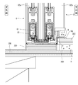
そして、既設窓100の室内側には、内窓8が取り付けられている。内窓8は、図4及び図5に示すように、四周枠組みした窓枠81と、窓枠81に引違いに納めた二枚の障子82a,82bからなる引違い窓であって、額縁200と、縦ふかし枠1又は横ふかし枠4に跨った位置に、窓枠81を縦ふかし枠1及び横ふかし枠4にネジ止めして取り付けられている。内窓8の窓枠81は、室内側端の四周に、内周側に向かって延びる起立片81aを有している。起立片81aは、窓枠81の左右辺及び下辺において、最も内周側に突出する部材である。ただし、左右辺においては、室外側端に設けたもう一つの起立片81bが同じだけ突出しており、下辺においては、障子82a,82b用のレール83が同じだけ突出している。また、上辺においては、障子82a,82b用のレール84がより内周側に突出している。そして、縦カバー材2及び横カバー材5の室内側見付面部21a,51aは、この起立片81aと内周側端面が面一になる長さに形成されており、縦カバー材2及び横カバー材5のシール部24,54が、起立片81aの室内側面に当接している。   An inner window 8 is attached to the indoor side of the existing window 100. As shown in FIGS. 4 and 5, the inner window 8 is a sliding window composed of a window frame 81 having a four-round frame and two shojis 82 a and 82 b that are housed in the window frame 81. The window frame 81 is attached to the vertical cover frame 1 and the horizontal cover frame 4 by screws at a position straddling the vertical cover frame 1 or the horizontal cover frame 4. The window frame 81 of the inner window 8 has standing pieces 81a that extend toward the inner circumference on the four sides of the indoor side end. The standing piece 81 a is a member that protrudes to the innermost side on the left and right sides and the lower side of the window frame 81. However, on the left and right sides, another upright piece 81b provided at the outdoor end protrudes by the same amount, and on the lower side, the rail 83 for the shoji 82a and 82b protrudes by the same amount. Further, on the upper side, the rails 84 for the shojis 82a and 82b protrude to the inner peripheral side. And the indoor side finding surface parts 21a and 51a of the vertical cover material 2 and the horizontal cover material 5 are formed in such a length that the upright piece 81a and the inner peripheral side end surface are flush with each other. The seal portions 24 and 54 of the cover material 5 are in contact with the indoor side surface of the upright piece 81a.

さらに、躯体開口部Sの周囲の躯体の室内側壁面Wには、断熱パネルHを取り付けてある。断熱パネルHの厚さは、額縁200の室内側壁面Wからの突出長さよりも薄く、額縁200の室内側端は、断熱パネルHの室内側面よりも室内側に突出している。そして、上記のとおり、縦カバー材2及び横カバー材5の外周側見込面部21b,51bが、縦ふかし枠1又は横ふかし枠4の室外側端よりもさらに室外側に延びており、断熱パネルHの小口が縦カバー材2又は横カバー材5の外周側見込面部21b,51bに当接している。   Furthermore, a heat insulating panel H is attached to the indoor side wall surface W of the casing around the casing opening S. The thickness of the heat insulating panel H is thinner than the protruding length of the frame 200 from the indoor side wall surface W, and the indoor side end of the frame 200 protrudes more indoors than the indoor side surface of the heat insulating panel H. And as above-mentioned, the outer peripheral side expected surface parts 21b and 51b of the vertical cover material 2 and the horizontal cover material 5 are further extended to the outdoor side rather than the outdoor side end of the vertical cover frame 1 or the horizontal cover frame 4, and a heat insulation panel The small edge of H is in contact with the outer peripheral side expected surface portions 21 b and 51 b of the vertical cover member 2 or the horizontal cover member 5.

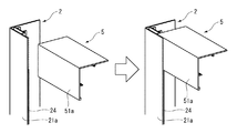
なお、図7に示すように、見切枠の角部においては、横カバー材5の端部が、縦カバー材2の室内側見付面部21aに呑み込まれる構造となっている。この際、縦カバー材2の室内側見付面部21aの先端の室外側面に設けたシール部24は、横カバー材5の上下幅の分だけ切除されており、縦カバー材2の室内側見付面部21aが、横カバー材5の室内側見付面部51aに当接している。なお、シール部24は、カッターの刃を室内側見付面部21aの室外側面に平行に密着させて当て、一度の作業で容易にそぎ落として除去することができるので、施工性が良好である。   As shown in FIG. 7, the corner portion of the parting frame has a structure in which the end portion of the horizontal cover member 5 is swallowed into the indoor side finding surface portion 21 a of the vertical cover member 2. At this time, the seal portion 24 provided on the outdoor side surface at the front end of the indoor-side finding surface portion 21a of the vertical cover material 2 is cut away by the vertical width of the horizontal cover material 5, and the indoor-side view of the vertical cover material 2 is obtained. The abutting surface portion 21 a is in contact with the indoor side finding surface portion 51 a of the lateral cover member 5. In addition, since the sealing part 24 can be applied by bringing the blade of the cutter into close contact with the outdoor side surface of the indoor side finding surface part 21a in parallel and can be easily scraped off and removed in one operation, the workability is good. .

このように構成した見切枠の第一実施形態によれば、縦カバー材2の小口に小口キャップ3が取り付けられており、さらに小口キャップ3の見込面部32が平坦になっていることから、室内側からは見込面部32の薄い端面しか見えず、小口キャップ3が目立たないので、すっきりとした外観となり意匠性が良好である。そして小口キャップ3が上下に突出しないので、躯体開口部Sに近接して他の構造物が設けられている場合(たとえば、上側にエアコンが設置されている場合など)でも、それと干渉することなく取り付けることができる。また、縦カバー材2の被固定部(中空部23)が略L字形のカバー部21の内側に形成してあって、被固定部(中空部23)及び小口キャップ3の固定部31(挿入突部31a及び挟持突部31b)が室内側から見えない。さらに、小口キャップ3を縦カバー材2に固定するネジ35も、カバー部21内側の挟持突部31bのネジ孔34bに挿入し、中空部23の壁面23aに螺入して、先端が挿入突部31aのネジ孔34a内、すなわち中空部23内に納まるものであるから、室内側からは一切見えないので、これらの点においても意匠性が良好である。また、縦カバー材2及び横カバー材5が、それぞれ縦ふかし枠1及び横ふかし枠4の室内側面及び外周側面を一体的に覆っており、さらに縦カバー材2及び横カバー材5の室内側見付面部21a,51aが、内窓8の窓枠81も覆っているので、室内側から見えるのは縦カバー材2及び横カバー材5のみとなり、一体的でフラットなすっきりとした意匠となる(内窓8の窓枠81の上側のレール84は横カバー材5から突出して見えるが、上側のレール84は元々見上げる位置にあるので、視認性への影響は小さい)。また、縦カバー材2及び横カバー材5の室内側見付面部21a,51aの先端に取り付けたシール部24,54が、内窓8の窓枠81の起立片81aに当接しているので、縦カバー材2及び横カバー材5と、内窓8との間の隙間が塞がれ一体的になっており、内周側の意匠性も高くなっている。さらに、躯体の室内側壁面Wに取り付けた断熱パネルHの小口が、縦カバー材2及び横カバー材5の外周側見込面部21b,51bに当接していることにより、小口面からの熱の流れを抑制してより断熱性能を高めるとともに、縦カバー材2又は横カバー材5と断熱パネルHとの間に額縁200が露出することを防いで意匠性を高めている。また、額縁200と、縦ふかし枠1又は横ふかし枠4とが、樹脂板からなる被覆材6で一体に覆われており、さらに縦ふかし枠1及び横ふかし枠4が樹脂製の縦カバー材2又は横カバー材5で覆われているので、縦ふかし枠1及び横ふかし枠4からの熱の流れを抑制して、断熱性能が向上している。また、内窓8を樹脂製のものとした場合には、樹脂板からなる被覆材6により質感が統一される。さらに、一般に、額縁は縦辺が横辺より数ミリ室内側に突出しているので、見切枠の角部において、縦カバー材2が横カバー材5を呑み込んでいることにより、見切枠の設置後も同様の質感とすることができる。なお、この見切枠の施工手順は、まず額縁200に縦ふかし枠1及び横ふかし枠4を取り付け、そこに内窓8を取り付け、その後横ふかし枠4に横カバー材5を取り付け、さらに縦カバー材2に小口キャップ3を取り付けてから、縦ふかし枠1に縦カバー材2を取り付ける。小口キャップ3を取り付けた状態で、縦カバー材2を縦ふかし枠1に取り付けるので、小口キャップ3に近接してエアコンなどの他の構造物が設けられている場合でも、干渉することなく取り付けることができる。ここでこの見切枠は、既設の躯体開口部Sに設置するものであるから、特に縦カバー材2については、現場で長さを調整することもありうる(横カバー材5は、端部が縦カバー材2に呑み込まれるので、厳密な長さ調整は必要ない)。その際、縦カバー材2は樹脂製であるから、切断は容易であるし、小口キャップ3を取り付けるためのネジ孔などは有していないから、切断加工のみすればよく、調整は容易である。また、横カバー材5を呑み込ませるためにシール部24を切除する作業も、カッターなどで容易に行うことができる。さらに、横カバー材5は、端部が縦カバー材2に呑み込まれており、熱により伸縮した場合でも、常に端部は縦カバー材2の室内側見付面部21aに覆い隠されるので、熱による伸縮が吸収される。   According to the first embodiment of the parting frame configured as described above, the small cap 3 is attached to the small opening of the vertical cover member 2, and the prospective surface portion 32 of the small cover 3 is flat. From the inside, only the thin end face of the prospective surface portion 32 can be seen, and the fore-edge cap 3 is not conspicuous, so that the appearance is neat and the design is good. And since the small cap 3 does not protrude up and down, even when another structure is provided close to the housing opening S (for example, when an air conditioner is installed on the upper side), it does not interfere with it. Can be attached. Further, the fixed portion (hollow portion 23) of the vertical cover member 2 is formed inside the substantially L-shaped cover portion 21, and the fixed portion (hollow portion 23) and the fixed portion 31 (insertion) of the small cap 3 are inserted. The protrusion 31a and the holding protrusion 31b) are not visible from the indoor side. Further, the screw 35 for fixing the fore edge cap 3 to the vertical cover member 2 is also inserted into the screw hole 34b of the clamping protrusion 31b inside the cover part 21, and screwed into the wall surface 23a of the hollow part 23, and the tip is inserted and protruded. Since it fits in the screw hole 34a of the part 31a, that is, in the hollow part 23, it cannot be seen at all from the indoor side, so that the design is also good in these respects. Further, the vertical cover member 2 and the horizontal cover member 5 integrally cover the indoor side surface and the outer peripheral side surface of the vertical cover frame 1 and the horizontal cover frame 4, respectively, and further the indoor side of the vertical cover member 2 and the horizontal cover member 5. Since the finding surface portions 21a and 51a also cover the window frame 81 of the inner window 8, only the vertical cover material 2 and the horizontal cover material 5 can be seen from the indoor side, and an integrated, flat and clean design is obtained. (Although the upper rail 84 of the window frame 81 of the inner window 8 appears to protrude from the lateral cover material 5, the upper rail 84 is originally in a position to be looked up, so the effect on visibility is small). Further, since the seal portions 24 and 54 attached to the front ends of the indoor side finding surface portions 21a and 51a of the vertical cover material 2 and the horizontal cover material 5 are in contact with the standing pieces 81a of the window frame 81 of the inner window 8, The gaps between the vertical cover member 2 and the horizontal cover member 5 and the inner window 8 are closed and integrated, and the design on the inner peripheral side is also improved. Furthermore, since the small edge of the heat insulation panel H attached to the indoor side wall surface W of the casing is in contact with the outer peripheral side expected surface portions 21b and 51b of the vertical cover material 2 and the horizontal cover material 5, the heat flow from the small surface. In addition to improving the heat insulation performance by preventing the frame 200 from being exposed between the vertical cover material 2 or the horizontal cover material 5 and the heat insulation panel H, the design is improved. Further, the frame 200 and the vertical cover frame 1 or the horizontal cover frame 4 are integrally covered with a covering material 6 made of a resin plate, and the vertical cover frame 1 and the horizontal cover frame 4 are made of resin. Since it is covered with 2 or the horizontal cover material 5, the heat flow from the vertical cover frame 1 and the horizontal cover frame 4 is suppressed, and the heat insulation performance is improved. Further, when the inner window 8 is made of resin, the texture is unified by the covering material 6 made of a resin plate. Further, generally, the frame has a vertical side protruding several millimeters indoors from the horizontal side, so that the vertical cover material 2 swallows the horizontal cover material 5 at the corner of the parting frame, so that after the parting frame is installed Can have a similar texture. The parting frame construction procedure is as follows. First, the vertical cover frame 1 and the horizontal cover frame 4 are attached to the frame 200, the inner window 8 is attached thereto, and then the horizontal cover member 5 is attached to the horizontal cover frame 4, and then the vertical cover. After the small cap 3 is attached to the material 2, the vertical cover material 2 is attached to the vertical cover frame 1. Since the vertical cover member 2 is attached to the vertical cover frame 1 with the small cap 3 attached, even when other structures such as an air conditioner are provided close to the small cap 3, the vertical cover member 2 should be attached without interference. Can do. Here, since the parting frame is installed in the existing housing opening S, the length of the vertical cover member 2 can be adjusted in the field (the horizontal cover member 5 has an end portion). Strict length adjustment is not necessary because it is swallowed by the vertical cover material 2). At that time, since the vertical cover material 2 is made of resin, it is easy to cut, and since it does not have a screw hole or the like for attaching the forehead cap 3, it is only necessary to perform cutting and adjustment is easy. . Moreover, the operation | work which cuts off the seal | sticker part 24 in order to swallow the horizontal cover material 5 can also be easily performed with a cutter. Further, the end portion of the horizontal cover member 5 is swallowed into the vertical cover member 2, and the end portion is always covered with the indoor-side finding surface portion 21a of the vertical cover member 2 even when it is expanded and contracted by heat. The expansion and contraction due to is absorbed.

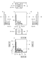
次に、第二実施形態について、図8に基づき説明する。見切枠の第二実施形態は、左右の縦ふかし枠、縦カバー材2及び小口キャップと、上側の横ふかし枠及び横カバー材とを備える三方枠形状のものであり、左右辺と上辺の構成は第一実施形態と同じである。そして下側については、図8に示すように、内窓8の窓枠81が額縁200に取り付けられており、縦ふかし枠および縦カバー材2の下端も額縁200に突き当たる構成となっている。また、躯体の室内側壁面Wに取り付けた断熱パネルHの小口も、額縁200に当接している。このように構成した見切枠の第二実施形態も、左右辺及び上辺において、第一実施形態と同様の作用効果を奏する。なお、この第二実施形態において、見切枠の下側に位置するのが額縁ではなく床面であってもよい。   Next, a second embodiment will be described based on FIG. The second embodiment of the parting frame is a three-sided frame shape including left and right vertical watermark frames, the vertical cover material 2 and the fore edge cap, and the upper horizontal watermark frame and the horizontal cover material. Is the same as in the first embodiment. On the lower side, as shown in FIG. 8, the window frame 81 of the inner window 8 is attached to the frame 200, and the vertical cover frame and the lower end of the vertical cover material 2 are also configured to abut against the frame 200. Further, the edge of the heat insulation panel H attached to the indoor side wall surface W of the housing is also in contact with the frame 200. The second embodiment of the parting frame configured in this way also has the same effects as the first embodiment on the left and right sides and the upper side. In the second embodiment, it may be the floor that is positioned below the parting frame instead of the frame.

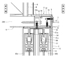
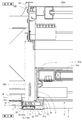
次に、第三実施形態について、図9〜図11に基づき説明する。見切枠の第三実施形態も、左右の縦ふかし枠1、縦カバー材2及び小口キャップと、上側の横ふかし枠及び横カバー材とを備える三方枠形状のものであり、左右辺と上辺の構成は第一実施形態と同じである。そして下側については、図10に示すように、既設の床面300の上に平板状の高さ調整材301が設けられていて、高さ調整材301の上に内窓8の窓枠81が取り付けられている。高さ調整材301の見込幅は窓枠81の見込幅とほぼ同じであり、高さ調整材301の室内側の床面300には、断熱パネルHが敷かれている。そして断熱パネルHの上面には、さらにリフォーム床材302が敷かれている。リフォーム床材302の室外側端には、略L字形のアングル材303が取り付けられており、アングル材303によって、リフォーム床材302の室外側端部の上面及び小口面が覆われている。また、高さ調整材301は、断熱パネルHと同じ厚さに調整されており、アングル材303の室外側面が、内窓8の窓枠81の起立片81aに当接していて、内窓8とリフォーム床材302の間の隙間が塞がれており、さらにアングル材303の上面と、起立片81aの上端部及びレール83の上端部とはほぼ同じ高さになっている。   Next, a third embodiment will be described with reference to FIGS. The third embodiment of the parting frame is also a three-sided frame shape including the left and right vertical cover frames 1, the vertical cover material 2 and the small cap, and the upper horizontal cover frame and the horizontal cover material. The configuration is the same as in the first embodiment. On the lower side, as shown in FIG. 10, a plate-like height adjusting material 301 is provided on the existing floor surface 300, and the window frame 81 of the inner window 8 is provided on the height adjusting material 301. Is attached. The expected width of the height adjusting material 301 is substantially the same as the expected width of the window frame 81, and the heat insulation panel H is laid on the floor surface 300 on the indoor side of the height adjusting material 301. A renovation floor material 302 is further laid on the upper surface of the heat insulation panel H. A substantially L-shaped angle member 303 is attached to the outdoor side end of the reformed flooring 302, and the angled material 303 covers the upper surface and the fore edge of the outdoor side end of the reformed flooring 302. Further, the height adjusting member 301 is adjusted to the same thickness as the heat insulating panel H, and the outdoor side surface of the angle member 303 is in contact with the standing piece 81 a of the window frame 81 of the inner window 8. The upper surface of the angle member 303, the upper end portion of the upright piece 81a, and the upper end portion of the rail 83 are substantially the same height.

そして、縦カバー材2の下端には、床面キャップ9が取り付けられている。床面キャップ9は、図11((a)〜(e)が五面図、(f)が縦カバー材2に取り付けた状態の説明図)に示すように、平板状の見込面部92と、挿入突部91を有しており、挿入突部91は、縦カバー材2の中空部23にちょうど嵌まる形状となっている。そして、見込面部92の室内側と外周側には、縦カバー材2のカバー部21から張り出す隙間塞ぎ部93が形成されており、さらに隙間塞ぎ部93の内周側端には、アングル材303を呑み込む呑み込み部94が形成されている。この床面キャップ9を縦カバー材2の下端に取り付けると、アングル材303の端部が呑み込み部94に呑み込まれ、隙間塞ぎ部93が、縦ふかし枠1と、リフォーム床材302の間の隙間を覆って塞ぐ。なお、床面キャップ9は、挿入突部91を縦カバー材2の中空部23に挿入することにより、水平方向の動きは規制されているが、上下方向には固定されておらず、リフォーム床材302に載った状態である。   A floor cap 9 is attached to the lower end of the vertical cover member 2. As shown in FIG. 11 ((a) to (e) is a five-sided view, and (f) is an explanatory view of a state in which the floor cap 9 is attached to the vertical cover member 2), An insertion protrusion 91 is provided, and the insertion protrusion 91 has a shape that fits into the hollow portion 23 of the vertical cover member 2. A gap closing portion 93 projecting from the cover portion 21 of the vertical cover member 2 is formed on the indoor side and the outer peripheral side of the prospective surface portion 92, and an angle member is provided on the inner peripheral side end of the gap closing portion 93. A swallowing portion 94 for swallowing 303 is formed. When the floor cap 9 is attached to the lower end of the vertical cover member 2, the end of the angle member 303 is squeezed into the squeezed portion 94, and the gap closing portion 93 is a gap between the vertical cover frame 1 and the renovated floor material 302. Cover and close. The floor cap 9 is restricted in movement in the horizontal direction by inserting the insertion protrusion 91 into the hollow portion 23 of the vertical cover member 2, but is not fixed in the vertical direction. It is in a state of being placed on the material 302.

このように構成した見切枠の第三実施形態も、左右辺及び上辺において、第一実施形態と同様の作用効果を奏する。そして、下側においては、リフォーム床材302と内窓8の下側の窓枠81とがほぼ同じ高さとなるので、段差がなく安全である。また、床面キャップ9の隙間塞ぎ部93が、リフォーム床材302の小口を覆うので、リフォーム床材302の縦ふかし枠1周りの形状を厳密に加工する必要がなく、施工性が良好である。   The third embodiment of the parting frame configured in this way also has the same effects as the first embodiment on the left and right sides and the upper side. And in the lower side, since the renovation flooring 302 and the window frame 81 on the lower side of the inner window 8 have substantially the same height, there is no step and it is safe. In addition, since the gap closing portion 93 of the floor cap 9 covers the small edge of the reformed floor material 302, it is not necessary to strictly process the shape of the reformed floor material 302 around the vertical cover frame 1 and the workability is good. .

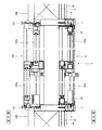
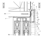
次に、第四実施形態について、図12〜17に基づき説明する。見切枠の第四実施形態は、左右の縦ふかし枠1、縦カバー材2及び小口キャップ3と、上下の横ふかし枠4及び横カバー材5とを備える四方枠形状のものである。見切枠を取り付ける躯体開口部Sには、窓(既設窓100)が設けられており、既設窓100の構成は、図15及び図16に示すように、第一実施形態の場合と同様である。また、既設窓100の上下左右の窓枠101の室内側には、やはり第一実施形態の場合と同様に、躯体開口部Sの見込面を覆う矩形板状の額縁200が取り付けられている。額縁200の室内側端は、躯体の室内側壁面Wよりも室内側に突出している。   Next, 4th embodiment is described based on FIGS. The fourth embodiment of the parting frame is of a four-sided frame shape including left and right vertical cover frames 1, vertical cover material 2 and fore edge cap 3, and upper and lower horizontal cover frames 4 and horizontal cover material 5. The housing opening S to which the parting frame is attached is provided with a window (existing window 100), and the configuration of the existing window 100 is the same as that of the first embodiment as shown in FIGS. . Further, similarly to the case of the first embodiment, a rectangular plate-shaped frame 200 that covers the prospective surface of the housing opening S is attached to the indoor side of the upper, lower, left, and right window frames 101 of the existing window 100. The indoor side end of the frame 200 protrudes more indoors than the indoor side wall surface W of the housing.

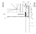
さらに、額縁200の室内側面には、見切材が取り付けられている。左右(縦)の額縁200に取り付けられた見切材は、図12に示すように、縦ふかし枠1と、縦カバー材2からなるものである。なお、図12は見切枠の左側部分を示すものであるが、右側部分はこれと左右対称な構造である。縦ふかし枠1は、断面が左右方向に長い略矩形のアルミ形材からなるものであり、左右方向幅が額縁200の左右方向幅よりも長く、額縁200から左右両側に突出するように、額縁200の室内側面にネジ止めして取り付けられている(内周側により長く突出している)。縦ふかし枠1の室内側面には、長手方向(上下方向)に延びる溝部を形成してあり、これが縦カバー材2を取り付けるための被嵌合部11となる。そして、左右の額縁200の内周側面には、樹脂板からなる被覆材6を取り付けてある。被覆材6の室内側端は、縦ふかし枠1の室外側面に当接している。   Further, a parting material is attached to the indoor side surface of the frame 200. The parting material attached to the left and right (vertical) picture frames 200 is composed of a vertical cover frame 1 and a vertical cover material 2 as shown in FIG. FIG. 12 shows the left part of the parting frame, but the right part has a symmetrical structure. The vertical pruning frame 1 is made of a substantially rectangular aluminum shape having a long cross section in the left-right direction, and the frame width is longer than the left-right width of the frame 200 and protrudes from the frame 200 to the left and right sides. It is attached to the side surface of the room 200 with screws (projecting longer on the inner peripheral side). A groove portion extending in the longitudinal direction (vertical direction) is formed on the indoor side surface of the vertical cover frame 1, and this is a fitted portion 11 for attaching the vertical cover material 2. And the coating | covering material 6 which consists of a resin board is attached to the inner peripheral side surface of the right and left frame 200. FIG. The indoor side end of the covering material 6 is in contact with the outdoor side surface of the vertical cover frame 1.

縦カバー材2は、硬質の樹脂製で、左右に延びる室内側見付面部21aと、室内側見付面部21aの外周側端から室外側に延びる外周側見込面部21bと、室内側見付面部21aの内周側端から室外側に延びる内周側見込面部21cからなる略コ字形のカバー部21を有し、カバー部21の内側(室内側見付面部21aの室外側かつ外周側見込面部21bの内周側かつ内周側見込面部21cの外周側)に、矩形の中空部23を形成してある。より詳しくは、外周側見込面部21bから内周側見込面部21cに向けて左右に延びる壁面23aが形成されており、この壁面23aと室内側見付面部21aの間の空間を左右に分割して、外周側の空間を中空部23としてある。この中空部23は、小口キャップ3を固定するための被固定部となる。そして、壁面23aには、室外側に突出する二つの爪部が形成されており、これが縦ふかし枠1の被嵌合部11に嵌合する嵌合部22となっている。嵌合部22を縦ふかし枠1の被嵌合部11に嵌合させると、室内側見付面部21a、外周側見込面部21b及び内周側見込面部21cが、それぞれ縦ふかし枠1の室内側面、外周側面及び内周側面を覆う。そして、外周側見込面部21bが縦ふかし枠1の外周側面に当接し、内周側見込面部21cが縦ふかし枠1の内周側面に当接する。さらに、外周側見込面部21bは、縦ふかし枠1の室外側端よりもさらに室外側に延びている。   The vertical cover member 2 is made of hard resin, and extends to the left and right, the indoor side finding surface portion 21a, the outer circumferential side facing surface portion 21b extending from the outer peripheral side end of the indoor side finding surface portion 21a to the outdoor side, and the indoor side finding surface portion. 21a has a substantially U-shaped cover portion 21 consisting of an inner peripheral side expected surface portion 21c extending from the inner peripheral side end to the outdoor side, and the inner side of the cover portion 21 (the outdoor side and outer peripheral side expected surface portion of the indoor side finding surface portion 21a). A rectangular hollow portion 23 is formed on the inner peripheral side of 21b and on the outer peripheral side of the inner peripheral side expected surface portion 21c. More specifically, a wall surface 23a extending left and right from the outer peripheral side surface 21b toward the inner peripheral surface 21c is formed, and the space between the wall surface 23a and the indoor side surface 21a is divided into left and right sides. The space on the outer peripheral side is a hollow portion 23. The hollow portion 23 serves as a fixed portion for fixing the fore edge cap 3. The wall surface 23 a is formed with two claw portions that protrude to the outdoor side, and this is the fitting portion 22 that fits into the fitted portion 11 of the vertical cover frame 1. When the fitting portion 22 is fitted to the fitted portion 11 of the vertical cover frame 1, the indoor side finding surface portion 21 a, the outer peripheral side looking surface portion 21 b, and the inner peripheral side looking surface portion 21 c are respectively connected to the indoor side surface of the vertical covering frame 1. The outer peripheral side surface and the inner peripheral side surface are covered. The outer peripheral side face 21 b comes into contact with the outer peripheral side of the vertical cover frame 1, and the inner peripheral side face 21 c comes into contact with the inner peripheral side of the vertical cover frame 1. Furthermore, the outer peripheral side anticipated surface portion 21 b extends further to the outdoor side than the outdoor side end of the vertical cover frame 1.

小口キャップ3は、硬質の樹脂製で、図17((a)〜(e)が五面図、(f)が縦カバー材2に取り付けた状態の説明図)に示すように、第一実施形態とほぼ同じ構成で、見込面部32と突条33の室内外方向長さを短くしたものである。縦カバー材2への固定方法も、第一実施形態と同じである。なお、図17に示したものは、左側の縦カバー材2の下端及び右側の縦カバー材2の上端に取り付けるものであり、左側の縦カバー材2の上端及び右側の縦カバー材2の下端に取り付けるものは、これと左右対称な形状となる。   The small cap 3 is made of a hard resin, as shown in FIG. 17 ((a) to (e) is a five-sided view, and (f) is an explanatory view of a state in which the vertical cover member 2 is attached). It is the structure substantially the same as a form, and shortens the indoor-outdoor direction length of the prospective surface part 32 and the protrusion 33. FIG. The fixing method to the vertical cover member 2 is also the same as in the first embodiment. 17 are attached to the lower end of the left vertical cover member 2 and the upper end of the right vertical cover member 2, and the upper end of the left vertical cover member 2 and the lower end of the right vertical cover member 2 are shown. What is attached to is a symmetrical shape.

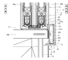
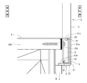
また、上下(横)の額縁200に取り付けられた見切材は、図13及び図14に示すように、横ふかし枠4と、横カバー材5からなるものである。横ふかし枠4は、断面が上下方向に長い略矩形で中空のアルミ形材からなるものであり、上下方向幅が額縁200の上下方向幅よりも長く、額縁200から上下両側に突出するように、額縁200の室内側面にネジ止めして取り付けられている。ただし、額縁200と横ふかし枠4の間には、板状のスペーサ201が挟まれている。これは、縦ふかし枠1に対する横ふかし枠4の室内外方向の位置を調整するためのものである。横ふかし枠4の内周側面と外周側面には、それぞれ爪部を形成してあり、これが横カバー材を取り付けるための被嵌合部41となっている。そして、上下の額縁200の内周側面と、スペーサ201の内周側面とに跨って樹脂板からなる被覆材6を取り付けてある。被覆材6により、額縁200とスペーサ201の境目が覆われ、上下の内周側面が完全な面一となっている。   Moreover, the parting material attached to the up-and-down (horizontal) frame 200 consists of the horizontal cover frame 4 and the horizontal cover material 5, as shown in FIG.13 and FIG.14. The horizontal pruning frame 4 is made of a substantially rectangular and hollow aluminum shape whose section is long in the vertical direction, and the vertical width is longer than the vertical width of the frame 200 and protrudes from the frame 200 to both the upper and lower sides. The screw is attached to the interior side of the frame 200 with screws. However, a plate-like spacer 201 is sandwiched between the frame 200 and the horizontal cover frame 4. This is for adjusting the position of the horizontal cover frame 4 in the indoor / outdoor direction with respect to the vertical cover frame 1. A claw portion is formed on each of the inner peripheral side surface and the outer peripheral side surface of the horizontal cover frame 4, and this is a fitted portion 41 for attaching the horizontal cover material. And the coating | covering material 6 which consists of a resin plate is attached ranging over the inner peripheral side surface of the upper and lower frame 200, and the inner peripheral side surface of the spacer 201. FIG. The covering material 6 covers the boundary between the frame 200 and the spacer 201, and the upper and lower inner peripheral side surfaces are completely flush with each other.

横カバー材5は、硬質の樹脂製で、上下に延びる室内側見付面部51aと、室内側見付面部51aの外周側端から室外側に延びる外周側見込面部51bと、室内側見付面部51aの内周側端から室外側に延びる内周側見込面部51cからなる略コ字形のカバー部51を有し、カバー部51の内側(外周側見込面部51bの内周側面と、内周側見込面部51cの外周側面)に、爪部を形成してある。この爪部は、横ふかし枠4の被嵌合部41に嵌合する嵌合部52となっている。嵌合部52を横ふかし枠4の被嵌合部41に嵌合させると、室内側見付面部51a、外周側見込面部51b及び内周側見込面部51cが、それぞれ横ふかし枠4の室内側面、外周側面及び内周側面を覆う。そして、外周側見込面部51bが横ふかし枠4の外周側面に当接し、内周側見込面部51cが横ふかし枠4の内周側面に当接する。さらに、外周側見込面部51bは、縦ふかし枠1の室外側端よりもさらに室外側に延びている。なお、見切枠の角部においては、縦カバー材2の内周側見込面部21cの内周側面に、横カバー材5の端部が当接している。   The side cover member 5 is made of a hard resin, and extends vertically to an indoor side finding surface part 51a, an outer peripheral side facing surface part 51b extending from the outer peripheral side end of the indoor side finding surface part 51a to the outdoor side, and an indoor side finding surface part. 51a has a substantially U-shaped cover portion 51 consisting of an inner peripheral side expected surface portion 51c extending from the inner peripheral side end of the outer peripheral side to the outdoor side, and the inner side of the cover portion 51 (the inner peripheral side surface of the outer peripheral side expected surface portion 51b A claw portion is formed on the outer peripheral side surface of the expected surface portion 51c. The claw portion serves as a fitting portion 52 that fits into the fitted portion 41 of the horizontal cover frame 4. When the fitting portion 52 is fitted to the fitted portion 41 of the horizontal cover frame 4, the indoor side finding surface portion 51 a, the outer peripheral side looking surface portion 51 b, and the inner peripheral side looking surface portion 51 c are respectively connected to the indoor side surface of the horizontal covering frame 4. The outer peripheral side surface and the inner peripheral side surface are covered. Then, the outer peripheral side surface 51 b comes into contact with the outer peripheral side surface of the horizontal cover frame 4, and the inner peripheral side surface portion 51 c comes into contact with the inner peripheral side surface of the horizontal cover frame 4. Furthermore, the outer peripheral side expected surface part 51 b extends further to the outdoor side than the outdoor side end of the vertical cover frame 1. In addition, in the corner | angular part of a parting frame, the edge part of the horizontal cover material 5 is contact | abutting to the inner peripheral side surface of the inner peripheral side expected surface part 21c of the vertical cover material 2. FIG.

そして、既設窓100の室内側には、内窓8が取り付けられている。内窓8自体の構成は、第一実施形態と同じであり、額縁200の室内側端に取り付けられている。そして、縦カバー材2及び横カバー材5の内周側見込面部21c,51cは、内窓8の窓枠81の起立片81aの内周側端と面一になっている。   An inner window 8 is attached to the indoor side of the existing window 100. The configuration of the inner window 8 itself is the same as that of the first embodiment, and is attached to the indoor side end of the frame 200. The inner peripheral side expected surface portions 21 c and 51 c of the vertical cover member 2 and the horizontal cover member 5 are flush with the inner peripheral end of the upright piece 81 a of the window frame 81 of the inner window 8.

さらに、躯体開口部Sの周囲の躯体の室内側壁面Wには、第一実施形態と同様に、断熱パネルHを取り付けてある。断熱パネルHの厚さは、額縁200の室内側壁面Wからの突出長さ(見切枠の上下辺においては、スペーサ201も含めた突出長さ)よりも薄く、額縁200(スペーサ201)の室内側端は、断熱パネルHの室内側面よりも室内側に突出している。そして、上記のとおり、縦カバー材2及び横カバー材5の外周側見込面部21b,51bが、縦ふかし枠1又は横ふかし枠4の室外側端よりもさらに室外側に延びており、断熱パネルHの小口が縦カバー材2又は横カバー材5の外周側見込面部21b,51bに当接している。   Furthermore, the heat insulation panel H is attached to the indoor side wall surface W of the casing around the casing opening S as in the first embodiment. The thickness of the heat insulating panel H is smaller than the protruding length of the frame 200 from the indoor side wall surface W (the protruding length including the spacer 201 on the upper and lower sides of the parting frame), and the chamber of the frame 200 (spacer 201). The inner end protrudes to the indoor side from the indoor side surface of the heat insulating panel H. And as above-mentioned, the outer peripheral side expected surface parts 21b and 51b of the vertical cover material 2 and the horizontal cover material 5 are further extended to the outdoor side rather than the outdoor side end of the vertical cover frame 1 or the horizontal cover frame 4, and a heat insulation panel The small edge of H is in contact with the outer peripheral side expected surface portions 21 b and 51 b of the vertical cover member 2 or the horizontal cover member 5.

このように構成した見切枠の第四実施形態は、額縁200が内窓8を取り付けるために十分な見込長さを有していて、額縁200を延長する必要がない場合に主として用いられる。そして、この第四実施形態によれば、縦カバー材2の小口に小口キャップ3が取り付けられており、さらに小口キャップ3の見込面部32が平坦になっていることから、室内側からは見込面部32の薄い端面しか見えず、小口キャップ3が目立たないので、すっきりとした外観となり意匠性が良好である。そして小口キャップ3が上下に突出しないので、躯体開口部Sに近接して他の構造物が設けられている場合(たとえば、上側にエアコンが設置されている場合など)でも、それと干渉することなく取り付けることができる。また、縦カバー材2の被固定部(中空部23)が略コ字形のカバー部21の内側に形成してあって、被固定部(中空部23)及び小口キャップ3の固定部31(挿入突部31a及び挟持突部31b)が室内側から見えない。さらに、小口キャップ3を縦カバー材2に固定するネジ35も、カバー部21内側の挟持突部31bのネジ孔34bに挿入し、中空部23の壁面23aに螺入して、先端が挿入突部31aのネジ孔34a内、すなわち中空部23内に納まるものであるから、室内側からは一切見えないので、これらの点においても意匠性が良好である。また、縦カバー材2及び横カバー材5が、それぞれ縦ふかし枠1及び横ふかし枠4の室内側面、外周側面及び内周側面を一体的に覆っており、さらに縦カバー材2及び横カバー材5が、内窓8の窓枠81も覆っているので、室内側から見えるのは縦カバー材2及び横カバー材5のみとなり、一体的でフラットなすっきりとした意匠となる(内窓8の窓枠81の上側のレール84は横カバー材5から突出して見えるが、上側のレール84は元々見上げる位置にあるので、視認性への影響は小さい)。さらに、躯体の室内側壁面Wに取り付けた断熱パネルHの小口が、縦カバー材2及び横カバー材5の外周側見込面部21b,51bに当接していることにより、小口面からの熱の流れを抑制してより断熱性能を高めるとともに、縦カバー材2又は横カバー材5と断熱パネルHとの間に額縁200やスペーサ201が露出することを防いで意匠性を高めている。また、額縁200が樹脂板からなる被覆材6で覆われているので断熱性が高く、さらに縦ふかし枠1及び横ふかし枠4が樹脂製の縦カバー材2又は横カバー材5で覆われているので、縦ふかし枠1及び横ふかし枠4からの熱の流れを抑制して、断熱性能が向上している。また、内窓8を樹脂製のものとした場合には、樹脂板からなる被覆材6により質感が統一される。なお、この見切枠の施工手順は、まず額縁200に縦ふかし枠1及び横ふかし枠4を取り付け、そこに内窓8を取り付け、その後横ふかし枠4に横カバー材5を取り付け、さらに縦カバー材2に小口キャップ3を取り付けてから、縦ふかし枠1に縦カバー材2を取り付ける。小口キャップ3を取り付けた状態で、縦カバー材2を縦ふかし枠1に取り付けるので、小口キャップ3に近接してエアコンなどの他の構造物が設けられている場合でも、干渉することなく取り付けることができる。ここでこの見切枠は、既設の躯体開口部Sに設置するものであるから、縦カバー材2や横カバー材5について、現場で長さを調整することもありうる。その際、縦カバー材2や横カバー材5は樹脂製であるから、切断は容易である。また、縦カバー材2の端部には小口キャップ3が取り付けられるが、縦カバー材2は小口キャップ3を取り付けるためのネジ孔などを有していないから、切断加工のみすればよく、調整は容易である。   The fourth embodiment of the parting frame configured as described above is mainly used when the frame 200 has a sufficient expected length for attaching the inner window 8 and it is not necessary to extend the frame 200. And according to this 4th embodiment, since the fore edge cap 3 is attached to the fore edge of the vertical cover material 2, and the expected surface part 32 of the fore edge cap 3 is flat, the expected surface part from the indoor side. Since only the thin end face of 32 is visible and the fore cap 3 is not conspicuous, the appearance is neat and the design is good. And since the small cap 3 does not protrude up and down, even when another structure is provided close to the housing opening S (for example, when an air conditioner is installed on the upper side), it does not interfere with it. Can be attached. Further, the fixed portion (hollow portion 23) of the vertical cover member 2 is formed inside the substantially U-shaped cover portion 21, and the fixed portion (hollow portion 23) and the fixed portion 31 (insertion) of the small cap 3 are inserted. The protrusion 31a and the holding protrusion 31b) are not visible from the indoor side. Further, the screw 35 for fixing the fore edge cap 3 to the vertical cover member 2 is also inserted into the screw hole 34b of the clamping protrusion 31b inside the cover part 21, and screwed into the wall surface 23a of the hollow part 23, and the tip is inserted and protruded. Since it fits in the screw hole 34a of the part 31a, that is, in the hollow part 23, it cannot be seen at all from the indoor side, so that the design is also good in these respects. Further, the vertical cover material 2 and the horizontal cover material 5 integrally cover the indoor side surface, the outer peripheral side surface, and the inner peripheral side surface of the vertical cover frame 1 and the horizontal cover frame 4, respectively. 5 also covers the window frame 81 of the inner window 8, so that only the vertical cover member 2 and the horizontal cover member 5 can be seen from the indoor side, and an integrated, flat, and clean design (of the inner window 8). The upper rail 84 of the window frame 81 appears to protrude from the lateral cover material 5, but the upper rail 84 is originally in a position to be looked up, so the effect on visibility is small). Furthermore, since the small edge of the heat insulation panel H attached to the indoor side wall surface W of the casing is in contact with the outer peripheral side expected surface portions 21b and 51b of the vertical cover material 2 and the horizontal cover material 5, the heat flow from the small surface. In addition to improving the heat insulation performance by preventing the frame 200 and the spacer 201 from being exposed between the vertical cover member 2 or the horizontal cover member 5 and the heat insulating panel H, the design is improved. Further, since the frame 200 is covered with the covering material 6 made of a resin plate, the heat insulation is high, and the vertical cover frame 1 and the horizontal cover frame 4 are covered with the resin vertical cover material 2 or the horizontal cover material 5. Therefore, the heat flow from the vertical cover frame 1 and the horizontal cover frame 4 is suppressed, and the heat insulation performance is improved. Further, when the inner window 8 is made of resin, the texture is unified by the covering material 6 made of a resin plate. The parting frame construction procedure is as follows. First, the vertical cover frame 1 and the horizontal cover frame 4 are attached to the frame 200, the inner window 8 is attached thereto, and then the horizontal cover member 5 is attached to the horizontal cover frame 4, and then the vertical cover. After the small cap 3 is attached to the material 2, the vertical cover material 2 is attached to the vertical cover frame 1. Since the vertical cover member 2 is attached to the vertical cover frame 1 with the small cap 3 attached, even when other structures such as an air conditioner are provided close to the small cap 3, the vertical cover member 2 should be attached without interference. Can do. Here, since the parting frame is installed in the existing housing opening S, the length of the vertical cover member 2 and the horizontal cover member 5 may be adjusted on site. At that time, since the vertical cover member 2 and the horizontal cover member 5 are made of resin, cutting is easy. Further, a small cap 3 is attached to the end of the vertical cover material 2, but the vertical cover material 2 does not have a screw hole for attaching the small cap 3, so that only a cutting process is required. Easy.

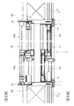
次に、第五実施形態について、図18〜図20に基づき説明する。見切枠の第五実施形態は、第四実施形態において内窓を取り付けない場合のものである。よって、各部材の構成は第四実施形態とまったく同じである。ただし、第四実施形態と比べて、額縁200に対する縦ふかし枠1及び横ふかし枠4の取付位置が外周側に寄っており、額縁200に取り付けた樹脂板からなる被覆材6の内周側面と、縦カバー材2又は横カバー材5の内周側見込面部21c,51cの内周側面とが面一になっている。このように縦ふかし枠1及び横ふかし枠4を内周側寄り(第四実施形態)と外周側寄り(第五実施形態)のどちらでも取り付けられるよう、縦ふかし枠1及び横ふかし枠4には、外周側と内周側の二箇所にネジの螺合箇所を設けてある。第五実施形態では、縦カバー材2及び横カバー材5により内窓の窓枠を覆い隠す必要がなく、被覆材6と縦カバー材2又は横カバー材5を面一にしたことで、すっきりとした外観となり意匠性が良好である。その他、第五実施形態は、内窓に関することを除いて、第四実施形態と同様の作用効果を奏する。   Next, a fifth embodiment will be described based on FIGS. The fifth embodiment of the parting frame is a case where the inner window is not attached in the fourth embodiment. Therefore, the configuration of each member is exactly the same as in the fourth embodiment. However, compared with the fourth embodiment, the mounting positions of the vertical cover frame 1 and the horizontal cover frame 4 with respect to the frame 200 are closer to the outer peripheral side, and the inner peripheral side surface of the covering material 6 made of a resin plate attached to the frame 200 The inner peripheral side surfaces of the inner peripheral side expected surface portions 21c and 51c of the vertical cover member 2 or the horizontal cover member 5 are flush with each other. In this way, the vertical cover frame 1 and the horizontal cover frame 4 are attached to the vertical cover frame 1 and the horizontal cover frame 4 so that either the inner peripheral side (fourth embodiment) or the outer peripheral side (fifth embodiment) can be attached. Are provided with screwed portions at two locations on the outer peripheral side and the inner peripheral side. In the fifth embodiment, it is not necessary to cover the window frame of the inner window with the vertical cover material 2 and the horizontal cover material 5, and the covering material 6 and the vertical cover material 2 or the horizontal cover material 5 are flush with each other. Appearance and design are good. In addition, the fifth embodiment has the same effects as the fourth embodiment except for the inner window.

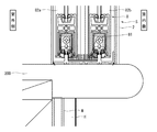
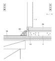
次に、第六実施形態について、図21に基づき説明する。見切枠の第六実施形態は、左右の縦ふかし枠、縦カバー材2及び小口キャップと、上側の横ふかし枠及び横カバー材とを備える三方枠形状のものであり、左右辺と上辺の構成は第五実施形態と同じであって、内窓は取り付けられていない。そして下側については、図21に示すように、床面300に断熱パネルHが敷かれており、断熱パネルHの上面には、さらにリフォーム床材302が敷かれている。リフォーム床材302の室外側端には、略L字形のアングル材303が取り付けられており、アングル材303によって、リフォーム床材302の室外側端部の上面及び小口面が覆われている。そして、アングル材303の室外側面は、縦ふかし枠及び横ふかし枠の室外側面と略面一になっている。さらに、アングル材303の室外側には、床面300からアングル材303の室外側面へと延びる傾斜部材304を取り付けてある。この傾斜部材304により、既設の床面300とリフォーム床材302との段差によるつまずきを防ぎ、またゴミの掃き出しも容易になっている。また、傾斜部材304により断熱パネルHの小口面が覆われるので、意匠性が向上するとともに、断熱パネルHの小口面からの熱損失及び小口面からの湿気の浸入による断熱パネルHの劣化を防止することができる。その他、第六実施形態は、左右辺及び上辺において、第五実施形態と同様の作用効果を奏する。   Next, a sixth embodiment will be described based on FIG. The sixth embodiment of the parting frame is a three-sided frame shape including left and right vertical watermark frames, vertical cover material 2 and fore cap, and an upper horizontal watermark frame and horizontal cover material. Is the same as that of the fifth embodiment, and the inner window is not attached. And about the lower side, as shown in FIG. 21, the heat insulation panel H is laid on the floor surface 300, and the reform floor material 302 is further laid on the upper surface of the heat insulation panel H. A substantially L-shaped angle member 303 is attached to the outdoor side end of the reformed flooring 302, and the angled material 303 covers the upper surface and the fore edge of the outdoor side end of the reformed flooring 302. The outdoor side surface of the angle member 303 is substantially flush with the outdoor side surfaces of the vertical cover frame and the horizontal cover frame. Further, an inclined member 304 extending from the floor surface 300 to the outdoor side surface of the angle member 303 is attached to the outdoor side of the angle member 303. The inclined member 304 prevents tripping due to a step between the existing floor surface 300 and the renovated floor material 302, and facilitates sweeping of dust. Moreover, since the small edge surface of the heat insulation panel H is covered by the inclined member 304, the design is improved, and the heat loss from the small edge surface of the heat insulation panel H and the deterioration of the heat insulation panel H due to moisture intrusion from the small edge surface are prevented. can do. In addition, the sixth embodiment has the same effects as the fifth embodiment on the left and right sides and the upper side.

本発明は、上記の実施形態に限定されない。たとえば、小口キャップの縦カバー材への固定については、ネジ止めではなく、嵌め込みにより固定するものとして、より施工性を向上させてもよい。この場合、小口キャップは、挟持突部を有していなくてもよい。またこの場合、小口キャップの脱落を防ぐため、たとえば縦カバー材の中空部の室外側の壁面に孔を形成し、小口キャップに爪を形成して、孔に爪を係合させて固定する構造にすることが望ましい。このようにすると、孔と爪が外側から見えないので、意匠性も良好である。さらに、縦カバー材は現場で長さを調整する(切断して短くする)こともあるので、予め孔を長手方向にわたって複数形成しておいて、切断しても爪と係合する孔を有する状態にすることが望ましい。また、躯体の室内側壁面に取り付ける断熱パネルが厚い場合又は額縁の室内側への突出長さが短い場合には、断熱パネルの室内側面が、額縁の室内側端よりも室内側に突出する場合もあるが、そのような場合にも、額縁に縦ふかし枠と縦カバー材、又は横ふかし枠と横カバー材を取り付けることで、断熱パネルの小口を縦カバー材又は横カバー材に当接させて、断熱性及び意匠性を向上させることができる。したがって、額縁の室内側への突出寸法や、断熱パネルの厚さ寸法にかかわらず、見切材(ふかし枠及びカバー材)を取り付けることで、断熱パネルの小口や額縁が露出することを防止できる。さらに、額縁(躯体開口部)の内周側面に取り付ける被覆材は、樹脂板からなるもののほか、木質シートや断熱フィルムからなるものなど、断熱性を有し、かつ取り付け後の内周側面を平坦にできるものであればよい。また、額縁(躯体開口部)の内周側面を露出させても意匠性や断熱性が問題にならない場合には、被覆材を設けなくてもよい。その場合、内窓は額縁(躯体開口部)の内周側面(及び縦ふかし枠又は横ふかし枠の内周側面)に直接取り付ければよい。さらに、本発明の見切枠は、額縁を有していない躯体開口部にも取り付けることができる。その場合、たとえばクロス張りの躯体壁面などに縦ふかし枠及び横ふかし枠を取り付けることになるが、取付面が額縁のように室内側に突出していないので、上記実施形態の縦カバー材及び横カバー材を取り付けると、外周側見込面部の室外側端が躯体壁面に干渉する。よって、この場合は外周側見込面部の室外側端部を切除し、縦ふかし枠又は横ふかし枠の室外側面と面一にして用いればよい。   The present invention is not limited to the above embodiment. For example, as for fixing the small cap to the vertical cover material, the workability may be further improved by fixing it by fitting rather than screwing. In this case, the fore edge cap does not need to have a clamping protrusion. In this case, in order to prevent the fore cap from falling off, for example, a hole is formed in the wall surface on the outdoor side of the hollow portion of the vertical cover member, a claw is formed in the fore cap, and the nail is engaged and fixed in the hole. It is desirable to make it. If it does in this way, since a hole and a nail cannot be seen from the outside, design nature is also good. Furthermore, since the length of the vertical cover material may be adjusted (cut and shortened) at the site, a plurality of holes are formed in advance in the longitudinal direction, and the holes that engage with the claws even when cut are provided. It is desirable to be in a state. Moreover, when the heat insulation panel attached to the indoor side wall surface of the frame is thick or when the projection length of the frame to the indoor side is short, the indoor side surface of the heat insulation panel projects to the indoor side from the indoor side end of the frame However, even in such a case, by attaching the vertical cover frame and the vertical cover material, or the horizontal cover frame and the horizontal cover material to the frame, the small edge of the heat insulation panel is brought into contact with the vertical cover material or the horizontal cover material. Thus, the heat insulation and the design can be improved. Therefore, regardless of the protruding dimension of the frame to the indoor side and the thickness dimension of the heat insulation panel, it is possible to prevent the small edge and the frame of the heat insulation panel from being exposed by attaching the parting material (the cover frame and the cover material). Furthermore, the covering material to be attached to the inner peripheral side surface of the frame (frame opening) has a heat insulating property such as a resin sheet, a wooden sheet or a heat insulating film, and the inner peripheral side surface after installation is flat. Anything can be used. Further, if the design and heat insulation properties do not become a problem even if the inner peripheral side surface of the frame (frame opening) is exposed, the covering material need not be provided. In that case, what is necessary is just to attach an inner window directly to the inner peripheral side surface (and the inner peripheral side surface of a vertical cover frame or a horizontal cover frame) of a frame (frame opening part). Furthermore, the parting frame of the present invention can be attached to a housing opening that does not have a frame. In that case, for example, a vertical cover frame and a horizontal cover frame are attached to a wall surface of a cross-stretched frame, but the mounting surface does not protrude to the indoor side like a frame, so the vertical cover material and the horizontal cover of the above embodiment are used. When a material is attached, the outdoor side end of the outer peripheral side anticipated surface part interferes with the frame wall surface. Therefore, in this case, it is only necessary to cut out the outdoor side end portion of the outer peripheral side expected surface portion and to be flush with the outdoor side surface of the vertical cover frame or the horizontal cover frame.

1 縦ふかし枠
2 縦カバー材
3 小口キャップ
11 被嵌合部
21 カバー部
21a 室内側見付面部
21b 外周側見込面部
22 嵌合部
23 被固定部(中空部)
23a 壁面
31 固定部
31a 挿入突部
31b 挟持突部
32 見込面部
S 躯体開口部
DESCRIPTION OF SYMBOLS 1 Vertical cover frame 2 Vertical cover material 3 Small cap 11 Covered part 21 Cover part 21a Indoor side finding surface part 21b Outer peripheral side expected surface part 22 Fitting part 23 Fixed part (hollow part)
23a Wall 31 Fixed part 31a Insertion protrusion 31b Holding protrusion 32 Expected surface part S Housing opening

Claims (2)

縦ふかし枠と、縦カバー材と、小口キャップとを備え、縦ふかし枠は、被嵌合部を有し、躯体開口部の縁部の室内側面に取り付けてあり、縦カバー材は、縦ふかし枠をカバーするものであり、室内側見付面部と、室内側見付面部の室外側に設けた嵌合部と、室内側見付面部の長手方向端部の室外側に設けた被固定部を有し、被固定部が嵌合部を回避する位置に設けてあって、嵌合部を縦ふかし枠の被嵌合部に室内側から嵌合させて取り付けてあり、小口キャップは、固定部と、平坦な見込面部を有し、固定部を縦カバー材の被固定部に係合させて固定してあることを特徴とする見切枠。   The vertical cover frame is provided with a vertical cover frame, a vertical cover material, and a small cap. The vertical cover frame has a fitted portion and is attached to the indoor side surface of the edge of the housing opening. The vertical cover material is a vertical cover material. Covering the frame, the indoor side finding surface part, the fitting part provided on the outdoor side of the indoor side finding surface part, and the fixed part provided on the outdoor side of the longitudinal end of the indoor side finding surface part The fixed part is provided at a position that avoids the fitting part, and the fitting part is fitted to the fitting part of the vertical cover frame from the indoor side, and the small cap is fixed. A parting frame and a flat expectation surface part, and the fixed part is engaged with the fixed part of the vertical cover member and fixed. 縦ふかし枠と、縦カバー材と、小口キャップとを備え、縦ふかし枠は、躯体開口部の縁部の室内側面に取り付けてあり、縦カバー材は、縦ふかし枠をカバーするものであり、縦ふかし枠に室内側から取り付けてあって、室内側見付面部と外周側見込面部を備えたカバー部を有するとともに、カバー部の内側に中空部を有しており、小口キャップは、挿入突部と、挟持突部とを有しており、挿入突部を縦カバー材の中空部に挿入し、挿入突部と挟持突部で中空部の壁面を挟み込んで固定してあることを特徴とする見切枠。   The vertical cover frame is provided with a vertical cover frame, a vertical cover material, and a small cap, and the vertical cover frame is attached to the indoor side surface of the edge of the housing opening, and the vertical cover material covers the vertical cover frame. It is attached to the vertical cover frame from the indoor side and has a cover part with an indoor side finding surface part and an outer peripheral side expecting surface part, and also has a hollow part inside the cover part. And a sandwiching projection, the insertion projection is inserted into the hollow portion of the vertical cover material, and the wall surface of the hollow portion is sandwiched and fixed between the insertion projection and the sandwiching projection. A parting frame to be.
JP2012239655A 2012-10-30 2012-10-30 Deadline Active JP6031326B2 (en)

Priority Applications (1)

Application Number Priority Date Filing Date Title
JP2012239655A JP6031326B2 (en) 2012-10-30 2012-10-30 Deadline

Applications Claiming Priority (1)

Application Number Priority Date Filing Date Title
JP2012239655A JP6031326B2 (en) 2012-10-30 2012-10-30 Deadline

Publications (2)

Publication Number Publication Date
JP2014088715A true JP2014088715A (en) 2014-05-15
JP6031326B2 JP6031326B2 (en) 2016-11-24

Family

ID=50790814

Family Applications (1)

Application Number Title Priority Date Filing Date
JP2012239655A Active JP6031326B2 (en) 2012-10-30 2012-10-30 Deadline

Country Status (1)

Country Link
JP (1) JP6031326B2 (en)

Cited By (1)

* Cited by examiner, † Cited by third party
Publication number Priority date Publication date Assignee Title
JP2021063348A (en) * 2019-10-11 2021-04-22 三協立山株式会社 Fitting

Citations (2)

* Cited by examiner, † Cited by third party
Publication number Priority date Publication date Assignee Title
JPS51134050U (en) * 1975-04-19 1976-10-29
JP2011153493A (en) * 2010-01-28 2011-08-11 Sankyo Tateyama Aluminium Inc Interior window

Patent Citations (2)

* Cited by examiner, † Cited by third party
Publication number Priority date Publication date Assignee Title
JPS51134050U (en) * 1975-04-19 1976-10-29
JP2011153493A (en) * 2010-01-28 2011-08-11 Sankyo Tateyama Aluminium Inc Interior window

Cited By (2)

* Cited by examiner, † Cited by third party
Publication number Priority date Publication date Assignee Title
JP2021063348A (en) * 2019-10-11 2021-04-22 三協立山株式会社 Fitting
JP7232742B2 (en) 2019-10-11 2023-03-03 三協立山株式会社 Fittings

Also Published As

Publication number Publication date
JP6031326B2 (en) 2016-11-24

Similar Documents

Publication Publication Date Title
JP5946869B2 (en) Outer wall mounting member and outer wall structure
JP2022179800A (en) Mounting structure for building attachment
JP6031326B2 (en) Deadline
JP2008144474A (en) Fireproof renovated door using existing door frame
JP6007067B2 (en) window
JP6644654B2 (en) Upper drainage structure at building opening
JP6007066B2 (en) Window, window manufacturing method
JP2010126910A (en) Sash
JP6202881B2 (en) Waterproof device for opening
JP2016121522A (en) Structure of external corner part of outer wall and external wall material construction
JP4446470B2 (en) Refurbished sash
JP2011208447A (en) Fittings
JP5486960B2 (en) Retrofitted airtight device for existing steel door
JP2005076393A (en) Opening-section device for repair
KR20190007923A (en) Curtain wall
JP5961095B2 (en) window
JP2007297831A (en) Cover frame and joinery
JP2006083698A (en) Remodeled door utilizing existing door frame
JP4147201B2 (en) Renovated door for door replacement using existing door frame
JP5302262B2 (en) Cover frame
JP2016033329A (en) Sash manufacturing method
JP4777228B2 (en) Glazing channel
JP7689035B2 (en) Renovated fittings
JP2005307696A5 (en)
JP2003120149A (en) Shutter device with soundproof function for construction

Legal Events

Date Code Title Description
A621 Written request for application examination

Free format text: JAPANESE INTERMEDIATE CODE: A621

Effective date: 20150427

A977 Report on retrieval

Free format text: JAPANESE INTERMEDIATE CODE: A971007

Effective date: 20160317

A131 Notification of reasons for refusal

Free format text: JAPANESE INTERMEDIATE CODE: A131

Effective date: 20160329

A521 Written amendment

Free format text: JAPANESE INTERMEDIATE CODE: A523

Effective date: 20160523

TRDD Decision of grant or rejection written
A01 Written decision to grant a patent or to grant a registration (utility model)

Free format text: JAPANESE INTERMEDIATE CODE: A01

Effective date: 20161018

A61 First payment of annual fees (during grant procedure)

Free format text: JAPANESE INTERMEDIATE CODE: A61

Effective date: 20161024

R150 Certificate of patent or registration of utility model

Ref document number: 6031326

Country of ref document: JP

Free format text: JAPANESE INTERMEDIATE CODE: R150