JP2014085657A - Display device - Google Patents
Display device Download PDFInfo
- Publication number
- JP2014085657A JP2014085657A JP2012237409A JP2012237409A JP2014085657A JP 2014085657 A JP2014085657 A JP 2014085657A JP 2012237409 A JP2012237409 A JP 2012237409A JP 2012237409 A JP2012237409 A JP 2012237409A JP 2014085657 A JP2014085657 A JP 2014085657A
- Authority
- JP
- Japan
- Prior art keywords
- display
- light
- case body
- display device
- mirror
- Prior art date
- Legal status (The legal status is an assumption and is not a legal conclusion. Google has not performed a legal analysis and makes no representation as to the accuracy of the status listed.)
- Pending
Links
- 238000005286 illumination Methods 0.000 claims abstract description 10
- 238000003384 imaging method Methods 0.000 claims abstract description 8
- 230000017525 heat dissipation Effects 0.000 claims abstract description 6
- 230000005855 radiation Effects 0.000 claims description 2
- 238000013021 overheating Methods 0.000 abstract 1
- 239000011347 resin Substances 0.000 description 6
- 229920005989 resin Polymers 0.000 description 6
- 230000005540 biological transmission Effects 0.000 description 4
- 238000010586 diagram Methods 0.000 description 3
- 229910052751 metal Inorganic materials 0.000 description 3
- 239000002184 metal Substances 0.000 description 3
- 239000004743 Polypropylene Substances 0.000 description 2
- 229910052782 aluminium Inorganic materials 0.000 description 2
- XAGFODPZIPBFFR-UHFFFAOYSA-N aluminium Chemical compound [Al] XAGFODPZIPBFFR-UHFFFAOYSA-N 0.000 description 2
- 239000004417 polycarbonate Substances 0.000 description 2
- 229920000515 polycarbonate Polymers 0.000 description 2
- -1 polypropylene Polymers 0.000 description 2
- 229920001155 polypropylene Polymers 0.000 description 2
- 239000002390 adhesive tape Substances 0.000 description 1
- 238000000151 deposition Methods 0.000 description 1
- 239000004973 liquid crystal related substance Substances 0.000 description 1
- 238000004519 manufacturing process Methods 0.000 description 1
- 238000000034 method Methods 0.000 description 1
- 230000009466 transformation Effects 0.000 description 1
Images


Abstract
Description
本発明は、発熱を伴う光源部を備えた表示装置に関するものである。 The present invention relates to a display device including a light source unit that generates heat.
従来より、フロントガラスの前方に虚像を表示させるヘッドアップディスプレイ装置が種々提案されており、例えば特許文献1に開示されている。ヘッドアップディスプレイ装置は、車両のダッシュボードに設けられ、フロントガラスに表示光を投影することで虚像を表示するものである。表示光を投影する表示手段としては様々な表示器が考えられるが、プロジェクタを用いたヘッドアップディスプレイ装置が特許文献2に開示されている。 Conventionally, various head-up display devices that display a virtual image in front of a windshield have been proposed. The head-up display device is provided on a dashboard of a vehicle and displays a virtual image by projecting display light onto a windshield. Various display devices are conceivable as display means for projecting display light, and a head-up display device using a projector is disclosed in Patent Document 2.
しかし、プロジェクタと、このプロジェクタが発した表示光を反射させる反射鏡(所謂折り返しミラー)との相対的な位置や角度に若干の微小なズレがあり、所望の虚像が得られない虞があった。例えば、ハウジングに固定された反射鏡が所望の角度に対して微小な傾きが生じると、虚像の一部が表示されないという問題を有していた。そこで、本願出願人は、表示器及び反射部材を放熱部材に固定した表示装置を特願2012−40957号として提案している。 However, there is a slight deviation in the relative position and angle between the projector and the reflecting mirror (so-called folding mirror) that reflects the display light emitted by the projector, and there is a possibility that a desired virtual image cannot be obtained. . For example, when the reflecting mirror fixed to the housing is slightly inclined with respect to a desired angle, there is a problem that a part of the virtual image is not displayed. Therefore, the applicant of the present application has proposed a display device in which a display and a reflecting member are fixed to a heat radiating member as Japanese Patent Application No. 2012-40957.
しかしながら、放熱部材に表示器を固定した表示装置は、放熱部材から表示器に熱が伝わり、表示器が過熱して損傷して、所望の表示ができなくなる虞があった。
本発明は、この問題に鑑みなされたものであり、表示器が過熱する虞が少ない表示装置を提供するものである。
However, in the display device in which the display is fixed to the heat radiating member, heat is transmitted from the heat radiating member to the display, the display is overheated and damaged, and a desired display cannot be performed.
The present invention has been made in view of this problem, and provides a display device in which the display device is less likely to overheat.
本発明は、照明光を発する光源部11と、前記照明光により照明される表示素子14と前記表示素子14を収納するケース体18とを有する表示器19と、前記光源部11及び前記表示器19を固定する放熱部材31とを備え、前記ケース体18が前記放熱部材31から離間するように前記表示器19を支持する支持部31b,31f,18mを設けたものである。
The present invention includes a
また、本発明は、照明光を発する光源部11と、前記照明光により照明される表示素子14と前記表示素子14を収納するケース体18とを有し表示光Lを発する表示器19と、前記表示器19が発した前記表示光Lを反射させる反射部材21と、前記反射部材21で反射された前記表示光Lが投影される結像部材26と、前記光源部11と前記表示器19と前記反射部材21と前記結像部材26とを固定する放熱部材31と、を備え、前記ケース体18が前記放熱部材31から離間するように前記表示器19を支持する支持部31b,31f,18mを設けたものである。
The present invention also includes a
また、本発明は、前記表示器19は、前記支持部31b,31f,18mによって前記放熱部材31に位置決めされる。
In the present invention, the
また、本発明は、前記支持部31f,18mは中空であるものである。
In the present invention, the
表示器が放熱部材から離間するように支持されているため、光源部からの熱が表示素子に伝わり難いため、表示素子が損傷する虞が少ない。 Since the display is supported so as to be separated from the heat radiating member, the heat from the light source part is difficult to be transmitted to the display element, so that the display element is less likely to be damaged.
以下、添付の図面に基づいて、本発明をヘッドアップディスプレイ装置に適用した一実施形態を説明する。図1乃至図5は、第一実施形態を示すものである。 Hereinafter, an embodiment in which the present invention is applied to a head-up display device will be described with reference to the accompanying drawings. 1 to 5 show a first embodiment.
ヘッドアップディスプレイ装置は、車両のダッシュボード1に設けられた表示装置2が投射する表示光Lをフロントガラス3によって車両運転者4側に反射させ、虚像Vを表示するものである。車両運転者4は、虚像Vを風景と重畳させて視認することができる。表示装置2は、第1ユニット100及び第2ユニット200を備えている。
The head-up display device displays the virtual image V by reflecting the display light L projected by the display device 2 provided on the dashboard 1 of the vehicle to the
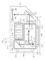
第1ユニット100は、プロジェクタ10,平面鏡(反射部材)21,透過型スクリーン(結像部材)26,ヒートシンク(放熱部材)31,ハウジング41等から構成されている。第2ユニット200は、反射器50,60,ハウジング71等から構成されている。
The
プロジェクタ10は、フィールドシーケンシャル方式によって、透過型スクリーン26に画像を表示させるものである。プロジェクタ10は、光源部11,ミラー部12,プリズム13,DMD(表示素子)14,投射レンズ15を有しており、ヒートシンク31に固定されている。プロジェクタ10の光源部11は、青色発光ダイオード11a,赤色発光ダイオード11b,緑色発光ダイオード11c,レンズ11d,11e,11f,反射ミラー11g,ダイクロイックミラー11h,11i,回路基板11kを有するものである。レンズ11d,11e,11f,反射ミラー11g,ダイクロイックミラー11h,11iは、フレーム11mに固定されている。
The
青色発光ダイオード11a,赤色発光ダイオード11b,緑色発光ダイオード11cは、夫々、青色光B,赤色光R,緑色光Gを発するものである。青色発光ダイオード11a,赤色発光ダイオード11b,緑色発光ダイオード11cは回路基板11kに搭載されている。回路基板11kはヒートシンク31に当接しており、青色発光ダイオード11a,赤色発光ダイオード11b,緑色発光ダイオード11cが発した熱は、回路基板11kを介して、ヒートシンク31によって放散される。
The blue light emitting diode 11a, the red
レンズ11d,11e,11fは、夫々、青色発光ダイオード11a,赤色発光ダイオード11b,緑色発光ダイオード11cが発した青色光B,赤色光R,緑色光Gを集光させる。反射ミラー11gは、青色発光ダイオード11aが発してレンズ11dで集光された青色光Bを反射させる。ダイクロイックミラー11hは、赤色発光ダイオード11bが発してレンズ11eで集光された赤色光Rを反射させると共に、反射ミラー11gで反射された青色光Bを透過させる。ダイクロイックミラー11iは、緑色発光ダイオード11cが発してレンズ11fで集光された緑色光Gを反射させると共に、反射ミラー11hで透過または反射された青色光B,赤色光Rを透過させる。
The
表示器19は、ミラー部12,プリズム13,DMD14,投射レンズ15をケース体18に収容したものである。表示器19は、光源部11とは直接的には接触していない。プリズム13は、ミラー部12からの光を透過させてDMD14に照射させる。DMD(Digital Micromirror Device)14は、多数の微小な鏡面を平面に配列した反射型表示素子であり、表示光Lを生成する。表示光Lは、プリズム13の傾斜面13aによって、投射レンズ15に向けて反射される。投射レンズ15は、表示光Lを拡大し、平面鏡21に投射する。投射レンズ15は、1枚のレンズで構成しても良いし、複数のレンズで構成しても良い。
The
平面鏡21は、支持部材23に保持されており、プロジェクタ10からの表示光Lを透過型スクリーン26に反射させる。透過型スクリーン26は支持部材24に保持されており、プロジェクタ10からの表示光Lが透過型スクリーン26に結像される。ヒートシンク31は、アルミニウム(Al)等の金属からなるものであり、複数の放熱フィン31aを有している。平面鏡21及び透過型スクリーン26は、保持部材23,24を介して、ヒートシンク31に固定されている。ハウジング41は、不透明な樹脂(例えばポリプロピレン)からなるものであり、プロジェクタ10,平面鏡21,透過型スクリーン26等を収容する。ハウジング41には、表示光Lが出射する窓部41aが形成されている。
The
反射器50は、平面鏡51及び支持部材52を有している。平面鏡51は、第1ユニット100からの表示光Lを凹面鏡61に反射させる。支持部材52は、ハウジング71に固定されており、平面鏡35を保持する。反射器60は、凹面鏡61,ミラーホルダー62,ステッピングモータ63,支持部材64を有している。凹面鏡61は、樹脂(例えばポリカーボネート)に金属(例えばアルミニウム)を蒸着させ反射面61aを形成したものである。反射面61aは凹面となっており、平面鏡51にて反射された表示光Lが拡大されて虚像Vが表示される。凹面鏡61はミラーホルダー62に両面粘着テープにより接着されている。ミラーホルダー62は樹脂(例えばABS)からなるものであり、歯車部65及び軸部66が一体に形成されている。
The
ステッピングモータ63の回動軸には歯車67が取付けられており、この歯車67は、ミラーホルダー62の歯車部65と噛合されている。凹面鏡61はミラーホルダー62と共に回動可能な状態で支持されており、ステッピングモータ63により凹面鏡61を回動させ、表示光Lの投射方向を調整することができる。車両運転者4は、押ボタンスイッチ(図示しない)を操作し表示光Lが目の位置に反射されるように(即ち、虚像Vを視認できるように)凹面鏡61の角度を調整する。
A
ハウジング71は、不透明な樹脂(例えばポリプロピレン)からなり、反射器50,60が収容される。ハウジング71には遮光壁71aが設けられており、太陽光等の外光が透過型スクリーン26に入射し虚像Vが見えにくくなる現象(ウォッシュアウト)を防止している。遮光壁71aは平板形状になっており、ハウジング71の上部から斜めに垂下するように形成されている。ハウジング71の上面には、表示光Lが出射する開口部71bが形成されており、この開口部71bには、透光性カバー72が貼着されている。透光性カバー72は、ポリカーボネート等の透明樹脂からなるものであり、湾曲形状になっている。
The
次に、図5に基づいて、表示器19の支持構造について詳述する。ヒートシンク31の前面31dには支持部31bが設けられている。ヒートシンク31の支持部31bは略円柱形状になっており、支持部31bの端部には凸部31cが形成されている。表示器19のケース体18には平板形状の突出部18aが設けられており、この突出部18aで表示器19が支持部31bに支持されている。支持部31bの凸部31cは、突出部18に形成された貫通孔18bに挿通されて、表示器19がヒートシンク31に位置決めされる。ケース体18は、支持部31bによって、底面18cがヒートシンク31の前面31dから所定間隔Hを有するように支持されている。
Next, the support structure of the
図6は第二実施形態を示す図である。第二実施形態は、支持部31f,突出部18d等が異なるだけであり、他の構成は第一実施形態と同様である。
FIG. 6 is a diagram showing a second embodiment. The second embodiment is different only in the
ヒートシンク31の前面31dには支持部31fが設けられている。ヒートシンク31の支持部31fは中空な円筒形状になっている。表示器19のケース体18には、側方に突出する平板形状の突出部18dが設けられており、この突出部18dで表示器19が支持部31fに支持されている。突出部18dには凹部18fが形成されており、この凹部18fに支持部31fの端部が嵌入されて、表示器19がヒートシンク31に位置決めされる。ケース体18は、支持部31fによって、底面18cがヒートシンク31の前面31dから所定間隔Hを有するように支持されている。
A
図7は第三実施形態を示す図である。第三実施形態は、突出部18k,支持部18m等が異なるだけであり、他の構成は第一実施形態と同様である。
FIG. 7 is a diagram showing a third embodiment. The third embodiment differs from the first embodiment only in the
表示器19のケース体18には、側方に突出する平板形状の突出部18kと、この突出部18kから垂加するように設けられた支持部18mとが設けられている。表示器19のケース体18は、突出部18kと支持部18mとで支持されている。ヒートシンク31には凹部31gが形成されており、この凹部31gに支持部18mが嵌入されて、表示器19がヒートシンク31に位置決めされる。ケース体18は、支持部18mによって、底面18cがヒートシンク31の前面31dから所定間隔Hを有するように支持されている。
The
各実施形態では、樹脂製のハウジング41に比して剛性が高い金属製のヒートシンク31にプロジェクタ10,平面鏡21,透過型スクリーン26が固定されているため、プロジェクタ10の光軸に対する平面鏡21,透過型スクリーン26の位置及び角度に誤差が生じる虞が少ない。また、各実施形態では、表示装置2が第1ユニット100と第2ユニット200とに分かれているため、組み付けが容易であり、製造コストを低減できる。更に、プロジェクタ10の表示器19が、ヒートシンク31から離間するように支持されているため、光源部11からの熱がヒートシンク31を介して、DMD14に伝わり難いため、DMD14が損傷する虞が少ない。
In each embodiment, the
なお、本発明は、各実施形態に限定されるものではなく、種々の変形が可能である。例えば、図8及び図9に示すように、支持部31f,18mを中空な円筒形状にすると共に、端部に位置決め用の凸部を設けても良い。また、各実施形態の表示素子はDMD14であったが、液晶表示素子であっても良い。
In addition, this invention is not limited to each embodiment, A various deformation | transformation is possible. For example, as shown in FIGS. 8 and 9, the
10 プロジェクタ
11 光源部
11B 青色発光ダイオード
11R 赤色発光ダイオード
11G 緑色発光ダイオード
14 DMD(表示素子)
18 ケース体
18m 支持部
19 表示器
21 平面鏡(反射部材)
26 透過型スクリーン(結像部材)
31 ヒートシンク(放熱部材)
31b 支持部
31f 支持部
L 表示光
DESCRIPTION OF
18
26 Transmission screen (imaging member)
31 Heat sink (heat dissipation member)
Claims (4)
Priority Applications (1)
| Application Number | Priority Date | Filing Date | Title |
|---|---|---|---|
| JP2012237409A JP2014085657A (en) | 2012-10-29 | 2012-10-29 | Display device |
Applications Claiming Priority (1)
| Application Number | Priority Date | Filing Date | Title |
|---|---|---|---|
| JP2012237409A JP2014085657A (en) | 2012-10-29 | 2012-10-29 | Display device |
Publications (1)
| Publication Number | Publication Date |
|---|---|
| JP2014085657A true JP2014085657A (en) | 2014-05-12 |
Family
ID=50788717
Family Applications (1)
| Application Number | Title | Priority Date | Filing Date |
|---|---|---|---|
| JP2012237409A Pending JP2014085657A (en) | 2012-10-29 | 2012-10-29 | Display device |
Country Status (1)
| Country | Link |
|---|---|
| JP (1) | JP2014085657A (en) |
Cited By (5)
| Publication number | Priority date | Publication date | Assignee | Title |
|---|---|---|---|---|
| WO2015198862A1 (en) * | 2014-06-26 | 2015-12-30 | 日本精機株式会社 | Head-up display device |
| JP2016011982A (en) * | 2014-06-27 | 2016-01-21 | 船井電機株式会社 | Projector and head-up display device |
| US9904052B2 (en) | 2014-06-06 | 2018-02-27 | Nitto Denko Corporation | Projection apparatus having polarizing plate which absorbes and reflects output light, and vehicle |
| WO2018150957A1 (en) | 2017-02-17 | 2018-08-23 | 日本精機株式会社 | Head-up display device |
| US11226484B2 (en) * | 2016-10-26 | 2022-01-18 | Nippon Seiki Co., Ltd. | Head-up display device |
-
2012
- 2012-10-29 JP JP2012237409A patent/JP2014085657A/en active Pending
Cited By (8)
| Publication number | Priority date | Publication date | Assignee | Title |
|---|---|---|---|---|
| US9904052B2 (en) | 2014-06-06 | 2018-02-27 | Nitto Denko Corporation | Projection apparatus having polarizing plate which absorbes and reflects output light, and vehicle |
| WO2015198862A1 (en) * | 2014-06-26 | 2015-12-30 | 日本精機株式会社 | Head-up display device |
| JP2016009155A (en) * | 2014-06-26 | 2016-01-18 | 日本精機株式会社 | Head-up display device |
| US10031341B2 (en) | 2014-06-26 | 2018-07-24 | Nippon Seiki Co., Ltd. | Head-up display device |
| JP2016011982A (en) * | 2014-06-27 | 2016-01-21 | 船井電機株式会社 | Projector and head-up display device |
| US11226484B2 (en) * | 2016-10-26 | 2022-01-18 | Nippon Seiki Co., Ltd. | Head-up display device |
| WO2018150957A1 (en) | 2017-02-17 | 2018-08-23 | 日本精機株式会社 | Head-up display device |
| US10788738B2 (en) | 2017-02-17 | 2020-09-29 | Nippon Seiki Co., Ltd. | Head-up display device |
Similar Documents
| Publication | Publication Date | Title |
|---|---|---|
| JP6985463B2 (en) | vehicle | |
| JP4883283B2 (en) | Display device | |
| JP6094203B2 (en) | Vehicle display device | |
| JP4831474B2 (en) | Head-up display device for vehicle | |
| JP6098868B2 (en) | Head-up display device | |
| JP4941070B2 (en) | Vehicle display device | |
| JP2016045252A (en) | Projection device and head-up display device | |
| JP2007065011A (en) | Head-up display device | |
| JP2013178308A (en) | Display device | |
| JP2014085657A (en) | Display device | |
| JP2010079169A (en) | Head-up display device | |
| JP2011150099A (en) | Mirror unit | |
| JP2019132868A (en) | Head-up display device | |
| JP2017203898A (en) | Mirror unit | |
| JP2017102230A (en) | Mirror unit | |
| JP6296862B2 (en) | Image display device | |
| JP2017049570A (en) | Mirror unit | |
| JP6020907B2 (en) | Display device | |
| JP6286569B2 (en) | Projection display device and heat dissipation method | |
| JP7304573B2 (en) | head-up display device | |
| JP2014174221A (en) | Light source device | |
| JP2010132207A (en) | Head-up display device | |
| JP4985921B2 (en) | Display device | |
| JP2017194615A (en) | Mirror unit | |
| JP2010134058A (en) | Head-up display device |