JP2014065337A - Head rest support structure and vehicle seat - Google Patents
Head rest support structure and vehicle seat Download PDFInfo
- Publication number
- JP2014065337A JP2014065337A JP2012209969A JP2012209969A JP2014065337A JP 2014065337 A JP2014065337 A JP 2014065337A JP 2012209969 A JP2012209969 A JP 2012209969A JP 2012209969 A JP2012209969 A JP 2012209969A JP 2014065337 A JP2014065337 A JP 2014065337A
- Authority
- JP
- Japan
- Prior art keywords
- stay
- seat back
- frame
- headrest
- guide
- Prior art date
- Legal status (The legal status is an assumption and is not a legal conclusion. Google has not performed a legal analysis and makes no representation as to the accuracy of the status listed.)
- Pending
Links
Images


Abstract
Description
本発明は、ヘッドレスト支持構造及び車両用シートに係り、ヘッドレストピラーを支持するブラケットをシートバックフレームに固定するヘッドレスト支持構造及び車両用シートに関する。 The present invention relates to a headrest support structure and a vehicle seat, and more particularly to a headrest support structure and a vehicle seat that fix a bracket that supports a headrest pillar to a seat back frame.
一般的に、車両用シートのヘッドレストは、シートバック内のシートバックフレームにヘッドレストピラーの支持ブラケットが固定され、この支持ブラケットに支持ガイドが挿入されて固着され、この支持ガイドにヘッドレストピラーが上下調整可能に嵌挿されることによって、シートバックで支持される構造となっている。
このような一般的なヘッドレストの支持構造では、シートバックやヘッドレストの形状に合わせて、支持ブラケットを微細に位置調整することが難しい。
そこで、支持ブラケットとシートバックフレームとの間に、中間ブラケットを介在させ、シートバックフレームに対する支持ブラケットの前後方向の位置調整を簡単に行えるようにした技術が提案されている(例えば特許文献1)。
In general, a headrest of a vehicle seat has a headrest pillar support bracket fixed to a seatback frame in the seatback, and a support guide is inserted and fixed to the support bracket. The headrest pillar is vertically adjusted to the support guide. By being inserted and possible, the structure is supported by the seat back.
In such a general headrest support structure, it is difficult to finely adjust the position of the support bracket in accordance with the shape of the seat back or the headrest.
Therefore, a technique has been proposed in which an intermediate bracket is interposed between the support bracket and the seat back frame so that the position of the support bracket in the front-rear direction relative to the seat back frame can be easily adjusted (for example, Patent Document 1). .
特許文献1は、シートバックフレームに固定され、ヘッドレストのステイが挿入されることによって、ヘッドレストを支持するステイ支持ブラケットを備えるヘッドレスト支持装置であって、シートバックフレームのヘッドレスト設置位置には、凹部が形成され、この凹部に、凹部側とは反対方向に開口した開口部を持つ略コ字状の開口ブラケットが取り付けられ、開口ブラケットの開口部に、ステイ支持ブラケットが装着される。
特許文献1の発明によれば、ステイ支持ブラケットを開口ブラケット内で前後方向へ位置調整した上で、その開口ブラケットに溶接固定すれば、ヘッドレストの前後方向の位置をヘッドレストの設計変更に対応して任意に設定できる。従って、開口ブラケットの成形型を一種類のみ用意すればよく、型コストを大幅に削減することができる。
According to the invention of
しかし、特許文献1の発明では、開口ブラケットの開口部側からの所定位置に、ステイ支持ブラケットを溶接により固定するため、ステイ支持ブラケットの側面が開口ブラケットの側面に支持されるだけで、ヘッドレストからの力が掛かるステイ支持ブラケットの後面が支持されず、ステイ支持ブラケットとシートバックフレームとの間の取付剛性が低くなっていた。
また、特許文献1の発明では、開口ブラケットを取付けるために、シートバックフレームに凹部を形成しており、シートバックフレーム自体の加工を要していた。
また、特許文献1では、従来技術として、ステイ支持ブラケットの後面が、開口ブラケットにより支持されたものも開示されているが、この技術では、開口ブラケットは、ステイ支持ブラケットの取付面よりも左右外側から後方に延出しているため、支持剛性が低くなっていた。
However, in the invention of
Further, in the invention of
本発明は、上記の課題に鑑みてなされたものであり、本発明の目的は、ヘッドレストピラーを支持するブラケットのシートバックフレームへの取付が簡単であると同時に、ブラケットを、ピラーを支持するガイドステイの取付面から後方に延出させることにより、剛性を高めたヘッドレスト支持構造及び車両用シートを提供することにある。 The present invention has been made in view of the above problems, and an object of the present invention is to easily mount the bracket supporting the headrest pillar to the seat back frame, and at the same time, to guide the bracket to the pillar. An object of the present invention is to provide a headrest support structure and a vehicle seat having increased rigidity by extending rearward from a stay mounting surface.
前記課題は、請求項1のヘッドレスト支持構造によれば、ヘッドレストのピラーが挿入されることによって、前記ヘッドレストを支持するヘッドレストのガイドステイを、車両用シートのシートバックを構成するシートバックフレームに、ヘッドレスト支持部材により固定するヘッドレスト支持構造であって、前記ヘッドレスト支持部材は、前記ガイドステイが取付けられるステイ取付部と、前記シートバックフレームに取付けられるフレーム取付部とを備え、前記フレーム取付部は、前記ステイ取付部から前記シートバックフレームの後方に向かって延出して、前記シートバックフレームの上面及び下面の少なくとも一方に取付けられること、により解決される。
According to the headrest support structure of
このように、フレーム取付部は、前記ステイ取付部から前記シートバックフレームの後方に向かって延出して、前記シートバックフレームの上面及び下面の少なくとも一方に取付けられるため、ステイ取付部の取付面から突出した位置で、ヘッドレスト支持部材をシートバックフレームに取り付けることができ、取付剛性を向上できる。 Thus, the frame mounting portion extends from the stay mounting portion toward the rear of the seat back frame and is attached to at least one of the upper surface and the lower surface of the seat back frame. At the protruding position, the headrest support member can be attached to the seat back frame, and the attachment rigidity can be improved.
このとき、請求項2のように、前記フレーム取付部は、前記ステイ取付部の上端から屈曲して前記シートバックフレームの後方に向かって延出していると好適である。
このように、ヘッドレスト支持部材の上部が、ステイ取付部の上端から屈曲してフレーム取付部に至る部分として構成され、この部分でガイドステイの後面を支持できるので、ガイドステイの支持剛性を向上できる。
At this time, it is preferable that the frame attachment portion bends from the upper end of the stay attachment portion and extends toward the rear of the seat back frame.
In this way, the upper portion of the headrest support member is configured as a portion that is bent from the upper end of the stay mounting portion and reaches the frame mounting portion, and the rear surface of the guide stay can be supported by this portion, so that the support rigidity of the guide stay can be improved. .
このとき、請求項3のように、前記ステイ取付部は、前記ガイドステイの前記シートバックフレーム側の外面に沿った形状のステイ取付面を備え、前記ガイドステイと前記シートバックフレームに挟まれて配置され、前記ガイドステイが前記ステイ取付面において前記ステイ取付部に取付けられる位置と、前記ステイ取付部が前記シートバックに当接する位置とが、同一平面上で隣接して配置されると好適である。
このように構成しているため、ヘッドレスト支持部材の大型化を抑制しつつ、ヘッドレストに大きな荷重が掛かった場合でも、ヘッドレストを安定して支持できる。
At this time, as in
Since it comprises in this way, even when a big load is applied to a headrest, the headrest can be supported stably, suppressing the enlargement of a headrest support member.
このとき、請求項4のように、前記フレーム取付部は、前記ステイ取付面の上端及び下端から屈曲して前記シートバックフレーム側にそれぞれ延出する上側延出部及び下側延出部を備え、該上側延出部及び下側延出部は、該上側延出部及び下側延出部の間に前記シートバックフレームを挟持すると好適である。
このように構成しているため、ヘッドレスト支持部材の剛性が向上すると共に、シートバックフレームへのヘッドレスト支持部材の取付剛性も向上する。
At this time, as described in claim 4, the frame attachment portion includes an upper extension portion and a lower extension portion that are bent from an upper end and a lower end of the stay attachment surface and extend to the seat back frame side, respectively. Preferably, the upper extension part and the lower extension part sandwich the seat back frame between the upper extension part and the lower extension part.
Since it comprises in this way, while the rigidity of a headrest support member improves, the attachment rigidity of the headrest support member to a seat back frame also improves.
このとき、請求項5のように、前記ステイ取付面のシート幅方向の幅は、前記ガイドステイの前記シート幅方向の幅よりも大きいと好適である。
このように構成しているため、ヘッドレスト支持部材とガイドステイとの取付剛性が向上する。
At this time, it is preferable that the width of the stay mounting surface in the sheet width direction is larger than the width of the guide stay in the sheet width direction.
With this configuration, the mounting rigidity between the headrest support member and the guide stay is improved.
このとき、請求項6のように、前記ヘッドレスト支持部材を前記シートバックフレームに取付けるときに用いられる位置決め部を備えると好適である。
このように構成しているため、ヘッドレスト支持部材の位置決めが容易になり、一層作業性が向上する。
At this time, it is preferable to provide a positioning portion used when attaching the headrest support member to the seat back frame.
Since it comprises in this way, positioning of a headrest support member becomes easy and workability | operativity improves further.
このとき、請求項7のように、前記ヘッドレスト支持部材は、前記ピラーを、支持ガイドを介して支持し、該支持ガイドは、外周面であって、前記ガイドステイが前記支持部材に溶接される箇所に対向する位置に、凹部を備えると好適である。
このように構成しているため、溶接の影響があっても、凹部で吸収できるので、溶接の熱歪みによりヘッドレストのピラーの取付性が低下することを抑制できる。
At this time, as described in claim 7, the headrest support member supports the pillar via a support guide, the support guide is an outer peripheral surface, and the guide stay is welded to the support member. It is preferable to provide a recess at a position facing the location.
Since it comprises in this way, even if it has the influence of welding, since it can absorb with a recessed part, it can suppress that the attachment property of the pillar of a headrest falls by the thermal distortion of welding.
このとき、請求項8のように、前記シートバックフレームに固定される左右の前記ガイドステイにそれぞれ取付けられる左右の前記ステイ取付部と、該左右のステイ取付部を連結する左右連結部を備えると好適である。
このように構成しているため、左右一対のガイドステイを取付けるためのヘッドレスト支持部材を一体として構成でき、部品点数が削減できると共に、ヘッドレスト支持部材の剛性が向上する。
At this time, as in claim 8, the left and right stay attaching portions respectively attached to the left and right guide stays fixed to the seat back frame and the left and right stay attaching portions are provided. Is preferred.
Since it comprises in this way, the headrest support member for attaching a pair of left and right guide stays can be constituted as one body, the number of parts can be reduced, and the rigidity of the headrest support member is improved.
このとき、請求項9のように、前記左右連結部は、凹部又は前記左右連結部を厚み方向に貫通する孔部を備えると好適である。
このように構成しているため、ヘッドレスト支持部材を軽量化できる。
At this time, as in a ninth aspect of the present invention, it is preferable that the left and right connecting portions include a recess or a hole that penetrates the left and right connecting portions in the thickness direction.
Since it comprises in this way, a headrest support member can be reduced in weight.
このとき、請求項10のように、前記ステイ取付部は、前記シートバックフレームの上方及び下方でそれぞれ前記ガイドステイに取付けられるステイ上方取付部及びステイ下方取付部であり、該ステイ上方取付部及びステイ下方取付部を連結する上下連結部を備え、該上下連結部は、前記シートバックフレームに取付けられると好適である。
このように構成しているため、ヘッドレスト支持部材の剛性が大幅に向上し、ヘッドレストの一層安定した支持が可能となる。
At this time, as in claim 10, the stay attaching portions are a stay upper attaching portion and a stay lower attaching portion that are attached to the guide stay above and below the seat back frame, respectively. It is preferable that an upper and lower connecting portion for connecting the stay lower attaching portion is provided, and the upper and lower connecting portion is attached to the seat back frame.
Since it comprises in this way, the rigidity of a headrest support member improves significantly and the still more stable support of a headrest is attained.
このとき、請求項11のように、前記上下連結部は、該上下連結部を厚み方向に貫通する溶接取付用の孔部を備えると好適である。
このように構成しているため、孔部でヘッドレスト支持部材とシートバックフレームとを溶接固定でき、ヘッドレスト支持部材の取付剛性が一層向上する。
At this time, as in the eleventh aspect, it is preferable that the upper and lower connecting portions include a welding attachment hole that penetrates the upper and lower connecting portions in the thickness direction.
Since it comprises in this way, a headrest support member and a seat back frame can be fixed by welding by a hole, and the attachment rigidity of a headrest support member improves further.
前記課題は、請求項12の車両用シートによれば、車両用シートのシートバックを構成するシートバックフレームと、ヘッドレストのピラーが挿入されることによって、前記ヘッドレストを支持するヘッドレストのガイドステイを、前記シートバックフレームに固定するヘッドレスト支持部材と、を備えた車両用シートであって、ートバックフレームに取付けられるフレーム取付部とを備え、前記フレーム取付部は、前記ステイ取付部から前記シートバックフレームの後方に向かって延出して、前記シートバックフレームの上面及び下面の少なくとも一方に取付けられること、により解決される。 According to the vehicle seat of claim 12, the problem is that the seat back frame constituting the seat back of the vehicle seat and the pillar of the headrest are inserted, so that the headrest guide stay that supports the headrest is inserted. A vehicle seat including a headrest support member fixed to the seatback frame, the frame mounting portion being attached to the seatback frame, wherein the frame mounting portion is connected to the seatback from the stay mounting portion. The problem is solved by extending toward the rear of the frame and being attached to at least one of the upper and lower surfaces of the seat back frame.
このように、フレーム取付部は、前記ステイ取付部から前記シートバックフレームの後方に向かって延出して、前記シートバックフレームの上面及び下面の少なくとも一方に取付けられるため、ステイ取付部の取付面から突出した位置で、ヘッドレスト支持部材をシートバックフレームに取り付けることができ、取付剛性を向上できる。 Thus, the frame mounting portion extends from the stay mounting portion toward the rear of the seat back frame and is attached to at least one of the upper surface and the lower surface of the seat back frame. At the protruding position, the headrest support member can be attached to the seat back frame, and the attachment rigidity can be improved.
請求項1の発明によれば、フレーム取付部は、前記ステイ取付部から前記シートバックフレームの後方に向かって延出して、前記シートバックフレームの上面及び下面の少なくとも一方に取付けられるため、ステイ取付部の取付面から突出した位置で、ヘッドレスト支持部材をシートバックフレームに取り付けることができ、取付剛性を向上できる。 According to the first aspect of the present invention, the frame attaching portion extends from the stay attaching portion toward the rear of the seat back frame and is attached to at least one of the upper surface and the lower surface of the seat back frame. The headrest support member can be attached to the seat back frame at a position protruding from the attachment surface of the part, and the attachment rigidity can be improved.
請求項2の発明によれば、ヘッドレスト支持部材の上部が、ステイ取付部の上端から屈曲してフレーム取付部に至る部分として構成され、この部分でガイドステイの後面を支持できるので、ガイドステイの支持剛性を向上できる。 According to the second aspect of the present invention, the upper portion of the headrest support member is configured as a portion that is bent from the upper end of the stay mounting portion and reaches the frame mounting portion, and this portion can support the rear surface of the guide stay. Support rigidity can be improved.
請求項3の発明によれば、ヘッドレスト支持部材の大型化を抑制しつつ、ヘッドレストに大きな荷重が掛かった場合でも、ヘッドレストを安定して支持できる。
According to the invention of
請求項4の発明によれば、ヘッドレスト支持部材の剛性が向上すると共に、シートバックフレームへのヘッドレスト支持部材の取付剛性も向上する。
請求項5の発明によれば、ヘッドレスト支持部材とガイドステイとの取付剛性が向上する。
According to the invention of claim 4, the rigidity of the headrest support member is improved, and the mounting rigidity of the headrest support member to the seat back frame is also improved.
According to the invention of claim 5, the mounting rigidity between the headrest support member and the guide stay is improved.
請求項6の発明によれば、ヘッドレスト支持部材の位置決めが容易になり、一層作業性が向上する。
請求項7の発明によれば、溶接の影響があっても、凹部で吸収できるので、溶接の熱歪みによりヘッドレストのピラーの取付性が低下することを抑制できる。
According to the invention of claim 6, the positioning of the headrest support member is facilitated, and the workability is further improved.
According to the seventh aspect of the present invention, even if there is an influence of welding, it can be absorbed by the concave portion, so that it is possible to suppress deterioration of the mounting properties of the headrest pillar due to thermal distortion of welding.
請求項8の発明によれば、左右一対のガイドステイを取付けるためのヘッドレスト支持部材を一体として構成でき、部品点数が削減できると共に、ヘッドレスト支持部材の剛性が向上する。 According to the eighth aspect of the present invention, the headrest support member for attaching the pair of left and right guide stays can be integrally formed, the number of parts can be reduced, and the rigidity of the headrest support member is improved.
請求項9の発明によれば、ヘッドレスト支持部材を軽量化できる。
請求項10の発明によれば、ヘッドレスト支持部材の剛性が大幅に向上し、ヘッドレストの一層安定した支持が可能となる。
According to invention of Claim 9, a headrest support member can be reduced in weight.
According to the invention of claim 10, the rigidity of the headrest support member is greatly improved, and the headrest can be supported more stably.
請求項11の発明によれば、孔部でヘッドレスト支持部材とシートバックフレームとを溶接固定でき、ヘッドレスト支持部材の取付剛性が一層向上する。 According to the eleventh aspect of the present invention, the headrest support member and the seat back frame can be fixed by welding at the hole, and the mounting rigidity of the headrest support member is further improved.
請求項12の発明によれば、前記ステイ取付部から前記シートバックフレームの後方に向かって延出して、前記シートバックフレームの上面及び下面の少なくとも一方に取付けられるため、ステイ取付部の取付面から突出した位置で、ヘッドレスト支持部材をシートバックフレームに取り付けることができ、取付剛性を向上できる。 According to the invention of claim 12, since it extends from the stay mounting portion toward the rear of the seat back frame and is attached to at least one of the upper surface and the lower surface of the seat back frame, At the protruding position, the headrest support member can be attached to the seat back frame, and the attachment rigidity can be improved.
以下、本発明の一実施形態に係る車両用シート及び車両用シートのシートフレームについて、図1〜図8を参照しながら説明する。
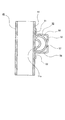
図1は、本発明の一実施形態に係る車両用シートの外観図である。図2は、本発明の一実施形態に係る車両用シートのシートフレームの外観図である。図3は、本発明の一実施形態に係るブラケットを介して上部フレームにヘッドレストピラー及び支持ガイドを支持するガイドステイを固定した状態を示す断面説明図である。図4は、本発明の一実施形態に係るブラケットを介して上部フレームにガイドステイを固定した状態を示す要部説明図である。図5は、本発明の一実施形態に係るブラケットの斜視図である。図6は、本発明の他の実施形態に係るブラケットを介して上部フレームにガイドステイを固定した状態を示す斜視説明図である。図7は、図6のA−A断面図である。図8は、本発明の更に他の実施例に係る図6のA−A断面図であって、上部フレームが潰し加工されていない変形例である。
Hereinafter, a vehicle seat and a seat frame of the vehicle seat according to an embodiment of the present invention will be described with reference to FIGS.
FIG. 1 is an external view of a vehicle seat according to an embodiment of the present invention. FIG. 2 is an external view of a seat frame of a vehicle seat according to an embodiment of the present invention. FIG. 3 is an explanatory cross-sectional view illustrating a state in which a guide stay that supports the headrest pillar and the support guide is fixed to the upper frame via the bracket according to the embodiment of the present invention. FIG. 4 is a main part explanatory view showing a state in which the guide stay is fixed to the upper frame through the bracket according to the embodiment of the present invention. FIG. 5 is a perspective view of a bracket according to an embodiment of the present invention. FIG. 6 is an explanatory perspective view showing a state in which the guide stay is fixed to the upper frame via a bracket according to another embodiment of the present invention. FIG. 7 is a cross-sectional view taken along the line AA of FIG. FIG. 8 is a cross-sectional view taken along the line AA of FIG. 6 according to still another embodiment of the present invention, and is a modification in which the upper frame is not crushed.
本実施の形態に係る車両用シートSは、図1で示すように、シートバックS1、着座部S2、ヘッドレストS3より構成されており、シートバックS1及び着座部S2は不図示のシートフレームにクッションパッド1a、2aを載置して、表皮材1b、2bで被覆されている。また、ヘッドレストS3は、不図示の芯材にパッド材3aを配して、表皮材3bで被覆して形成され、ヘッドレストピラー14により支持される。
As shown in FIG. 1, the vehicle seat S according to the present embodiment includes a seat back S1, a seat portion S2, and a headrest S3. The seat back S1 and the seat portion S2 are cushioned on a seat frame (not shown). The
シートバックS1は、シートバックフレーム1に、クッションパッド1aを載置して、クッションパッド1aの上から表皮材1bにより覆われており、乗員の背中を後方から支持するものである。シートバックフレーム1は、図2に示すように、左右に離間して配置され上下方向に延在する一対のサイドフレーム20と、一対のサイドフレーム20の上端部を連結する上部フレーム11と、下端部を連結する下部フレーム12とにより枠状に構成されている。
The seat back S1 mounts the
サイドフレーム20は、板金をプレス加工して成形され、前端の辺が湾曲して前端の下側部分が前方に張り出した略D字状の略板体からなる。
上部フレーム11は、パイプ状体からなり、シート幅方向に延びてシートバックフレーム1の上部を構成する上枠部11aと、上枠部11aの両端が垂直に湾曲して下方に向かって延出する上部フレーム側部11bとから構成されている。
The
The
上枠部11aには、ヘッドレストピラー14を支持する支持ガイド15を支持するガイドステイ40が、ヘッドレスト支持部材としてのブラケット30を介して設けられている。
ヘッドレストピラー14は、図2、図3に示すように、一対の金属製の棒状体からなる。
支持ガイド15は、合成樹脂を筒状に成型した部材であり、ヘッドレストピラー14を内部に格納可能な筒状部15aと、筒状部の上方に一体に設けられ、ガイドステイ40内に挿入されたときにガイドステイ40の上端よりも上方に露出する頭部15bと、を備えている。
支持ガイド15の外側面には、図3に示すように、凹部15cが設けられている。凹部15cは、ガイドステイ40の後面41がブラケット30と溶接される位置に対向している。
図4に示すように、ヘッドレストピラー14は、筒状の支持ガイド15に挿入されて固定され、支持ガイド15は、筒状のガイドステイ40に挿入されて嵌合される。
A guide stay 40 that supports a
As shown in FIGS. 2 and 3, the
The
As shown in FIG. 3, a
As shown in FIG. 4, the
ガイドステイ40は、図2、図3に示すように、金属板が曲げ加工により巻かれることによって形成された略角筒状からなり、シート後方の後面41を備えている。
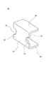
ブラケット30は、金属板が断面コ字状(U字状)に曲げ加工されてなり、図2〜図5に示すように、平板状のステイ取付部31と、ステイ取付部31の上下両端から垂直に屈曲してシート後方へ延出する平板状の上側延出部35及び下側延出部36と、からなる。
ステイ取付部31は、上側延出部35及び下側延出部36が延出する側の面が、上枠部11aのシート前方側の面が溶接固定されるフレーム前面取付面32を構成し、上側延出部35及び下側延出部36の延出側の逆の面が、ガイドステイ40のシート後方側の面が溶接固定されるステイ取付面33を構成している。ステイ取付面33は、特許請求の範囲のステイ取付部に対応する。
なお、本実施形態では、上側延出部35及び下側延出部36は、平板状で、ステイ取付部31の上下両端から垂直に屈曲して延出しているが、これに限定されるものではなく、例えば、ステイ取付部31の上下両端から、ステイ取付部31に対して鋭角又は鈍角の角度を持って延出してもよい。また、ステイ取付部31の上下両端から延出し、更に、上枠部11aの湾曲面を囲むように再度屈曲していてもよい。
また、ステイ取付部31と上側延出部35及び下側延出部36とを、上枠部11aの湾曲面に沿って湾曲する形状として構成してもよい。例えば、円柱体が軸方向に沿って切断された形状としてもよい。
As shown in FIGS. 2 and 3, the
The
In the
In the present embodiment, the
Moreover, you may comprise the
上側延出部35と下側延出部36との間の距離は、上部フレーム11の上枠部11a外面の上下方向の径に等しくなっており、ブラケット30を上部フレーム11の上枠部11aに取付けたときに、上側延出部35及び下側延出部36の間に上枠部11aを挟持可能に構成されている。
ステイ取付部31は、幅方向の両端で、上下方向の中央に、半円形の切欠き部34が一対設けられている。切欠き部34は、ブラケット30を上枠部11aに溶接するときに、溶接用の位置決めピンを係止させて、溶接時の位置決めをするために用いられる。
ブラケット30は、ステイ取付部31の上下方向の中央、すなわち図3の水平面P上において、ステイ取付部31の幅方向に沿って、上枠部11aに溶接されるため、切欠き部34は、ブラケット30と上枠部11aとの溶接ビードの延長線上に位置する。溶接時の位置決めとして、切欠き部34の代わりに、凹部や孔部を設けてもよい。
ブラケット30の板厚は、ガイドステイ40及び上枠部11aの厚みよりも薄く形成されている。これにより、前後方向の大型化が抑制されると同時に、ブラケット30の加工が容易になる。
なお、本実施形態では、ブラケット30は、ガイドステイ40毎に設けられるが、一対のブラケット30が左右連結部で連結され一体に形成された形状から構成してもよい。
The distance between the upper extending
The
The
The thickness of the
In addition, in this embodiment, although the
次に、ガイドステイ40のブラケット30を介した上枠部11aへの取付について説明する。
図2、図4に示すように、上枠部11aは、パイプ状のまま、潰し加工がされることなく、2箇所に、ブラケット30が取付けられている。
ブラケット30のフレーム前面取付面32の上下方向の中央と、上枠部11aの前面とが、当接している。また、ブラケット30の上側延出部35のシート後方の端部35aと、上枠部11aの上面とが、当接した状態で、この当接した位置で、端部35aに沿ってシート幅方向に溶接固定され、ブラケット30の下側延出部36のシート後方の端部36aと、上枠部11aの下面とが、当接した状態で、この当接した位置で、端部36aに沿ってシート幅方向に溶接固定されている。
上枠部11aの上端及び下端(頂点)より後方に、ブラケット30の上側延出部35及び下側延出部36aと、上枠部11aとの溶接部を備えている。これにより、ブラケット30が上枠部11aの頂点に当接し、一層安定した支持が可能となる。
上側延出部35と下側延出部36との高さ方向における間で、円筒形の上枠部11aとガイドステイ40がブラケット30に当接しており、安定した支持が可能になっている。
Next, attachment of the guide stay 40 to the
As shown in FIGS. 2 and 4,
The center of the frame front
On the rear side from the upper end and the lower end (vertex) of the
The cylindrical
また、ブラケット30のステイ取付面33とガイドステイ40の後面41とが、当接した状態で、ステイ取付面33の上端及び下端のそれぞれに沿って、ステイ取付面33と後面41とが溶接されている。溶接位置は、図3に、溶接ビードWとして示している。また、ガイドステイ40の後面41の左右端部に沿って、上下方向に、ステイ取付面33と後面41とが溶接されている。
ステイ取付面33と後面41との間の溶接は、溶接ビードWが、ステイ取付面33と後面41とが当接する領域よりもはみ出すように行われると好適である。つまり、図3に示すように、溶接ビードWが、ブラケット30が、上枠部11aを支持する領域よりも、幅が大きくなるように溶接すると、ガイドステイ40の支持剛性が向上し、好適である。
Further, the
The welding between the
支持ガイド15の外側面には、図3に示すように、凹部15cが設けられているので、ステイ取付面33と後面41とが溶接された部分に熱歪みにより微小な突起が生じた場合であっても、凹部15cでその影響を吸収でき、支持ガイド15とガイドステイ40とのがたつき等を防止できる。
ガイドステイ40と、ステイ取付面33と、上枠部11aの前面のステイ取付面33に最も近い部分とは、図3に示すように、同一水平面P上に配置されている。また、上枠部11aとブラケット30とが溶接された箇所と、ブラケット30とガイドステイ40が当接する箇所とが、上部フレーム11の長手方向に直交する同一鉛直平面上に配置され、一層安定した支持が可能になっている。
また、ガイドステイ40とブラケット30とが当接する部分の上端及び下端と同じ高さの位置で、ブラケット30が上枠部11aに取り付けられており、ガイドステイ40の回転を抑制可能になっている。
As shown in FIG. 3, the outer surface of the
The
Further, the
本実施形態では、ブラケット30が断面コ字状に形成されているため、ヘッドレストS3に掛かる荷重を安定して受けることができる。
ヘッドレストS3に乗員からの荷重が加わると、ヘッドレストS3は、後方へ移動する方向の荷重を受ける。このとき、ガイドステイ40上部から上枠部11aに掛かる荷重を、ブラケット30の上側延出部35で受け止めることができる。また、荷重が上枠部11aに掛かることで、上枠部11aが下方に移動するような力が発生するが、この力を、ブラケット30の下側延出部36で受け止めることができる。その結果、ブラケット30により、ヘッドレストS3に掛かる荷重を安定して受けることが可能となる。
In the present embodiment, since the
When a load from an occupant is applied to the headrest S3, the headrest S3 receives a load in a direction of moving backward. At this time, the load applied from the upper part of the guide stay 40 to the
また、図2〜図5のブラケット30の代わりに、図6、図7に示すブラケット50を用いてもよい。
ブラケット50は、図7に示すように、潰し加工により上枠部11aの前面に設けられた凹面11cが形成された箇所に取付けられる。
ブラケット50は、金属板が曲げ加工されてなり、図6、図7に示すように、平板状のフレーム後面取付部52と、フレーム後面取付部52の上下両端から鈍角に屈曲して延出する平面板状の上側延出部55及び下側延出部56と、上側延出部55及び下側延出部56の左右方向の端部から上下方向へ広がるように鋭角に屈曲してそれぞれ延出するステイ上方取付部51と、ステイ下方取付部53からなる。上側延出部55、下側延出部56、フレーム後面取付部52が、特許請求の範囲の上下連結部及び左右連結部に対応する。
フレーム後面取付部52の上側延出部55、下側延出部56が延出する側の面には、上枠部11aの後面が固定され、ステイ上方取付部51のフレーム後面取付部52逆側の面は、一対のガイドステイ40の後面の上方部分に固定され、ステイ下方取付部53のフレーム後面取付部52逆側の面は、一対のガイドステイ40の後面の下方部分に固定される。
フレーム後面取付部52には、図6に示すように、フレーム後面取付部52を厚み方向に貫通する孔部57が形成されている。
Moreover, you may use the
As shown in FIG. 7, the
As shown in FIGS. 6 and 7, the
The rear surface of the
As shown in FIG. 6, the frame rear
上側延出部55、下側延出部56は、ブラケット50を上枠部11aに取付けたときに、上側延出部55及び下側延出部56の間に上枠部11aを挟持し、上側延出部55、下側延出部56のステイ上方取付部51側の面が、上枠部11aの上面及び下面に当接するように構成されている。
上側延出部55、下側延出部56は、フレーム後面取付部52逆側の端部で、一対のステイ上方取付部51又はステイ下方取付部53の間の部分が、切欠かれた形状となっている。このように構成することにより、ブラケット50の軽量化が図られ、ステイ上方取付部51又はステイ下方取付部53の位置決めが容易になっている。
また、フレーム後面取付部52の孔部57の間には、孔部58が設けられ、ブラケット50の軽量化が図られている。なお、孔部58の代わりに、フレーム後面取付部52を貫通しない凹部を設けてもよい。
The upper extending
The
In addition, a
次に、ガイドステイ40のブラケット50を介した上枠部11aへの取付について説明する。
上枠部11aは、ブラケット50が取り付けられる箇所に、潰し加工により、凹面11cが形成されている。
ブラケット50のフレーム後面取付部52の上下方向の中央と、上枠部11aの後面とが、当接しており、孔部57で、溶接固定されている。
また、ブラケット30の一対のステイ上方取付部51及び一対のステイ下方取付部53とガイドステイ40の後面41とが、当接した状態で、一対のステイ上方取付部51の上端又はステイ下方取付部53の下端に沿って、溶接されている。
図7に示すように、ブラケット50の上側延出部55の下面と、上枠部11aの上面とが、当接し、ブラケット50の下側延出部56の下面と、上枠部11aの上面とが、当接している。また、上枠部11aの凹面11cは、ガイドステイ40の後面41に当接している。
なお、図7の例では、上枠部11aが潰し加工された箇所にブラケット50が取付けられているが、図8のように、潰し加工をしていない上枠部11aに取付けられていてもよい。
Next, attachment of the guide stay 40 to the
The
The center in the vertical direction of the frame rear
The upper ends of the pair of stay upper mounting
As shown in FIG. 7, the lower surface of the
In the example of FIG. 7, the
S 車両用シート
S1 シートバック
S2 着座部
S3 ヘッドレスト
P 水平面
W 溶接ビード
1 シートバックフレーム
1a、2a クッションパッド
1b、2b 表皮材
3a パッド材
3b 表皮材
11 上部フレーム
11a 上枠部
11b 上部フレーム側部
11c 凹面
12 下部フレーム
14 ヘッドレストピラー
15 支持ガイド
15a 筒状部
15b 頭部
15c 凹部
20 サイドフレーム
30、50 ブラケット
31 ステイ取付部
32 フレーム前面取付面
33 ステイ取付面
34 切欠き部
35、55 上側延出部
35a、36a 端部
36、56 下側延出部
40 ガイドステイ
41 後面
51 ステイ上方取付部
52 フレーム後面取付部
53 ステイ下方取付部
57、58 孔部
DESCRIPTION OF SYMBOLS S Vehicle seat S1 Seat back S2 Seat part S3 Headrest P Horizontal surface
Claims (12)
前記ヘッドレスト支持部材は、前記ガイドステイが取付けられるステイ取付部と、前記シートバックフレームに取付けられるフレーム取付部とを備え、
該フレーム取付部は、前記ステイ取付部から前記シートバックフレームの後方に向かって延出して、前記シートバックフレームの上面及び下面の少なくとも一方に取付けられることを特徴とするヘッドレスト支持構造。 A headrest support structure for fixing a headrest guide stay supporting the headrest to a seatback frame constituting a seatback of a vehicle seat by a headrest support member by inserting a pillar of the headrest,
The headrest support member includes a stay attachment portion to which the guide stay is attached, and a frame attachment portion to be attached to the seat back frame,
The headrest support structure, wherein the frame attaching portion extends from the stay attaching portion toward the rear of the seat back frame and is attached to at least one of an upper surface and a lower surface of the seat back frame.
前記ガイドステイが前記ステイ取付面において前記ステイ取付部に取付けられる位置と、前記ステイ取付部が前記シートバックに当接する位置とが、同一平面上で隣接して配置されることを特徴とする請求項1又は2記載のヘッドレスト支持構造。 The stay mounting portion includes a stay mounting surface having a shape along an outer surface of the guide stay on the seat back frame side, and is disposed between the guide stay and the seat back frame.
The position where the guide stay is attached to the stay attachment portion on the stay attachment surface and the position where the stay attachment portion abuts on the seat back are arranged adjacent to each other on the same plane. Item 3. A headrest support structure according to item 1 or 2.
該上側延出部及び下側延出部は、該上側延出部及び下側延出部の間に前記シートバックフレームを挟持することを特徴とする請求項3記載のヘッドレスト支持構造。 The frame attachment portion includes an upper extension portion and a lower extension portion that are bent from the upper end and the lower end of the stay attachment surface and extend to the seat back frame side, respectively.
4. The headrest support structure according to claim 3, wherein the upper extension part and the lower extension part sandwich the seat back frame between the upper extension part and the lower extension part.
該支持ガイドは、外周面であって、前記ガイドステイが前記支持部材に溶接される箇所に対向する位置に、凹部を備えることを特徴とする請求項1乃至6いずれか記載のヘッドレスト支持構造。 The headrest support member supports the pillar via a support guide,
The headrest support structure according to any one of claims 1 to 6, wherein the support guide is provided with a recess at a position facing an outer peripheral surface of the support stay where the guide stay is welded to the support member.
該ステイ上方取付部及びステイ下方取付部を連結する上下連結部を備え、
該上下連結部は、前記シートバックフレームに取付けられることを特徴とする請求項1乃至9いずれか記載のヘッドレスト支持構造。 The stay attaching portion is a stay upper attaching portion and a stay lower attaching portion that are attached to the guide stay above and below the seat back frame, respectively.
An upper and lower connecting portion for connecting the stay upper mounting portion and the stay lower mounting portion;
The headrest support structure according to claim 1, wherein the upper and lower connecting portions are attached to the seat back frame.
ヘッドレストのピラーが挿入されることによって、前記ヘッドレストを支持するヘッドレストのガイドステイを、前記シートバックフレームに固定するヘッドレスト支持部材と、を備えた車両用シートであって、
前記ヘッドレスト支持部材は、前記ガイドステイが取付けられるステイ取付部と、前記シートバックフレームに取付けられるフレーム取付部とを備え、
該フレーム取付部は、前記ステイ取付部から前記シートバックフレームの後方に向かって延出して、前記シートバックフレームの上面及び下面の少なくとも一方に取付けられることを特徴とする車両用シート。
A seat back frame constituting a seat back of a vehicle seat;
A headrest support member that fixes a headrest guide stay that supports the headrest to the seatback frame by inserting a pillar of the headrest, and a vehicle seat,
The headrest support member includes a stay attachment portion to which the guide stay is attached, and a frame attachment portion to be attached to the seat back frame,
The vehicle seat, wherein the frame attachment portion extends from the stay attachment portion toward the rear of the seat back frame and is attached to at least one of an upper surface and a lower surface of the seat back frame.
Priority Applications (1)
| Application Number | Priority Date | Filing Date | Title |
|---|---|---|---|
| JP2012209969A JP2014065337A (en) | 2012-09-24 | 2012-09-24 | Head rest support structure and vehicle seat |
Applications Claiming Priority (1)
| Application Number | Priority Date | Filing Date | Title |
|---|---|---|---|
| JP2012209969A JP2014065337A (en) | 2012-09-24 | 2012-09-24 | Head rest support structure and vehicle seat |
Related Child Applications (1)
| Application Number | Title | Priority Date | Filing Date |
|---|---|---|---|
| JP2017085228A Division JP6480499B2 (en) | 2017-04-24 | 2017-04-24 | Headrest support structure and vehicle seat |
Publications (2)
| Publication Number | Publication Date |
|---|---|
| JP2014065337A true JP2014065337A (en) | 2014-04-17 |
| JP2014065337A5 JP2014065337A5 (en) | 2015-11-05 |
Family
ID=50742185
Family Applications (1)
| Application Number | Title | Priority Date | Filing Date |
|---|---|---|---|
| JP2012209969A Pending JP2014065337A (en) | 2012-09-24 | 2012-09-24 | Head rest support structure and vehicle seat |
Country Status (1)
| Country | Link |
|---|---|
| JP (1) | JP2014065337A (en) |
Cited By (2)
| Publication number | Priority date | Publication date | Assignee | Title |
|---|---|---|---|---|
| JP2018020657A (en) * | 2016-08-03 | 2018-02-08 | テイ・エス テック株式会社 | Vehicle seat |
| KR101998490B1 (en) * | 2017-12-29 | 2019-07-09 | 한화큐셀앤드첨단소재 주식회사 | Optional headrest assembly |
Citations (3)
| Publication number | Priority date | Publication date | Assignee | Title |
|---|---|---|---|---|
| JPH0259650U (en) * | 1988-10-25 | 1990-05-01 | ||
| JP2011011651A (en) * | 2009-07-02 | 2011-01-20 | Nihon Technica Co Ltd | Mounting structure of bracket |
| JP2012075613A (en) * | 2010-09-30 | 2012-04-19 | Ts Tech Co Ltd | Headrest holding structure |
-
2012
- 2012-09-24 JP JP2012209969A patent/JP2014065337A/en active Pending
Patent Citations (3)
| Publication number | Priority date | Publication date | Assignee | Title |
|---|---|---|---|---|
| JPH0259650U (en) * | 1988-10-25 | 1990-05-01 | ||
| JP2011011651A (en) * | 2009-07-02 | 2011-01-20 | Nihon Technica Co Ltd | Mounting structure of bracket |
| JP2012075613A (en) * | 2010-09-30 | 2012-04-19 | Ts Tech Co Ltd | Headrest holding structure |
Cited By (2)
| Publication number | Priority date | Publication date | Assignee | Title |
|---|---|---|---|---|
| JP2018020657A (en) * | 2016-08-03 | 2018-02-08 | テイ・エス テック株式会社 | Vehicle seat |
| KR101998490B1 (en) * | 2017-12-29 | 2019-07-09 | 한화큐셀앤드첨단소재 주식회사 | Optional headrest assembly |
Similar Documents
| Publication | Publication Date | Title |
|---|---|---|
| JP5695243B2 (en) | Seat frame and vehicle seat | |
| JP2006213201A (en) | Vehicular seat equipped with seat back able to absorb impact | |
| JP6170139B2 (en) | Vehicle seat and its seat frame | |
| CN108437866B (en) | Seat device | |
| US8696060B2 (en) | Seat back frame | |
| JP2011178194A (en) | Seat for vehicle | |
| JP6005165B2 (en) | Vehicle seat and seat frame of vehicle seat | |
| US10245988B2 (en) | Vehicle seat provided with seat belt retractor | |
| JP2015044502A (en) | Vehicle seat | |
| JP5915603B2 (en) | Seat back frame structure | |
| JP5720510B2 (en) | Vehicle seat | |
| JP2014065337A (en) | Head rest support structure and vehicle seat | |
| JP6059069B2 (en) | Armrests for vehicle seats | |
| US9663009B2 (en) | Conveyance seat | |
| JP6480499B2 (en) | Headrest support structure and vehicle seat | |
| JP5297054B2 (en) | Vehicle seat | |
| JP6396522B2 (en) | Seat frame for vehicle seat | |
| JP5733936B2 (en) | Vehicle seat | |
| JP2015003674A (en) | Bracket fixing structure of seat back frame | |
| JP2008296661A (en) | Frame structure for seatback | |
| JP2016120918A (en) | Vehicle seat and seat frame thereof | |
| JP6070433B2 (en) | Vehicle seat | |
| JP2008296663A (en) | Frame structure for seatback | |
| JP2018127108A (en) | Vehicle seat and manufacturing method therefor | |
| JP6495365B2 (en) | Vehicle seat |
Legal Events
| Date | Code | Title | Description |
|---|---|---|---|
| A521 | Request for written amendment filed |
Free format text: JAPANESE INTERMEDIATE CODE: A523 Effective date: 20150915 |
|
| A621 | Written request for application examination |
Free format text: JAPANESE INTERMEDIATE CODE: A621 Effective date: 20150915 |
|
| A977 | Report on retrieval |
Free format text: JAPANESE INTERMEDIATE CODE: A971007 Effective date: 20160714 |
|
| A131 | Notification of reasons for refusal |
Free format text: JAPANESE INTERMEDIATE CODE: A131 Effective date: 20160802 |
|
| A521 | Request for written amendment filed |
Free format text: JAPANESE INTERMEDIATE CODE: A523 Effective date: 20161003 |
|
| A02 | Decision of refusal |
Free format text: JAPANESE INTERMEDIATE CODE: A02 Effective date: 20170124 |