JP2014046880A - Saddle-riding type vehicle - Google Patents
Saddle-riding type vehicle Download PDFInfo
- Publication number
- JP2014046880A JP2014046880A JP2012193180A JP2012193180A JP2014046880A JP 2014046880 A JP2014046880 A JP 2014046880A JP 2012193180 A JP2012193180 A JP 2012193180A JP 2012193180 A JP2012193180 A JP 2012193180A JP 2014046880 A JP2014046880 A JP 2014046880A
- Authority
- JP
- Japan
- Prior art keywords
- seat
- angle sensor
- vehicle
- sensor
- frame
- Prior art date
- Legal status (The legal status is an assumption and is not a legal conclusion. Google has not performed a legal analysis and makes no representation as to the accuracy of the status listed.)
- Pending
Links
Images
Classifications
-
- B—PERFORMING OPERATIONS; TRANSPORTING
- B62—LAND VEHICLES FOR TRAVELLING OTHERWISE THAN ON RAILS
- B62J—CYCLE SADDLES OR SEATS; AUXILIARY DEVICES OR ACCESSORIES SPECIALLY ADAPTED TO CYCLES AND NOT OTHERWISE PROVIDED FOR, e.g. ARTICLE CARRIERS OR CYCLE PROTECTORS
- B62J1/00—Saddles or other seats for cycles; Arrangement thereof; Component parts
- B62J1/12—Box-shaped seats; Bench-type seats, e.g. dual or twin seats
-
- B—PERFORMING OPERATIONS; TRANSPORTING
- B62—LAND VEHICLES FOR TRAVELLING OTHERWISE THAN ON RAILS
- B62J—CYCLE SADDLES OR SEATS; AUXILIARY DEVICES OR ACCESSORIES SPECIALLY ADAPTED TO CYCLES AND NOT OTHERWISE PROVIDED FOR, e.g. ARTICLE CARRIERS OR CYCLE PROTECTORS
- B62J45/00—Electrical equipment arrangements specially adapted for use as accessories on cycles, not otherwise provided for
- B62J45/40—Sensor arrangements; Mounting thereof
- B62J45/41—Sensor arrangements; Mounting thereof characterised by the type of sensor
- B62J45/415—Inclination sensors
- B62J45/4151—Inclination sensors for sensing lateral inclination of the cycle
-
- B—PERFORMING OPERATIONS; TRANSPORTING
- B62—LAND VEHICLES FOR TRAVELLING OTHERWISE THAN ON RAILS
- B62K—CYCLES; CYCLE FRAMES; CYCLE STEERING DEVICES; RIDER-OPERATED TERMINAL CONTROLS SPECIALLY ADAPTED FOR CYCLES; CYCLE AXLE SUSPENSIONS; CYCLE SIDE-CARS, FORECARS, OR THE LIKE
- B62K11/00—Motorcycles, engine-assisted cycles or motor scooters with one or two wheels
- B62K11/02—Frames
- B62K11/04—Frames characterised by the engine being between front and rear wheels
- B62K11/06—Frames characterised by the engine being between front and rear wheels the frame being of single-beam type
Landscapes
- Engineering & Computer Science (AREA)
- Mechanical Engineering (AREA)
- Automatic Cycles, And Cycles In General (AREA)
- Motorcycle And Bicycle Frame (AREA)
- Axle Suspensions And Sidecars For Cycles (AREA)
Abstract
Description
本発明は、傾斜角センサを備える鞍乗型車両に関する。 The present invention relates to a straddle-type vehicle including an inclination angle sensor.
自動二輪車の転倒時にエンジンの動作を停止させるために、自動二輪車に傾斜角センサが設けられる。特許文献1には、傾斜角センサの取り付け構造が記載されている。 In order to stop the operation of the engine when the motorcycle falls, an inclination angle sensor is provided in the motorcycle. Patent Document 1 describes a mounting structure of an inclination angle sensor.
特許文献1に記載の自動二輪車においては、車両左右に1本ずつ車体フレームが設けられる。左右の車体フレームの後端部近傍の部分に、左右の車体フレームを連結する連結部材が設けられる。連結部材の一端部近傍および他端部近傍から上方に向かって延びるように左右一対のパイプ部材が設けられる。一対のパイプ部材の上端部が連結パイプにより固定される。連結パイプに、シートキャッチ取り付け部材が設けられる。シートキャッチ取り付け部材にシートキャッチが設けられる。傾斜角センサは、シートキャッチに取り付けられる。この状態で、傾斜角センサはシートと後輪との間に位置する。 In the motorcycle described in Patent Document 1, one body frame is provided on each side of the vehicle. A connecting member for connecting the left and right body frames is provided in the vicinity of the rear end portions of the left and right body frames. A pair of left and right pipe members are provided so as to extend upward from the vicinity of one end and the vicinity of the other end of the connecting member. The upper ends of the pair of pipe members are fixed by the connecting pipe. A seat catch attachment member is provided on the connecting pipe. A seat catch is provided on the seat catch mounting member. The tilt angle sensor is attached to the seat catch. In this state, the tilt angle sensor is located between the seat and the rear wheel.
上記の自動二輪車に設けられるECU(Electronic Control Unit;電子制御ユニット)は、シートキャッチに取り付けられた傾斜角センサからの信号に基づいて車両の傾斜角度を検出する。ECUは、車両の傾斜角度が通常のバンク角を超えて傾いた際にエンジンを停止させる。 An ECU (Electronic Control Unit) provided in the motorcycle detects the inclination angle of the vehicle based on a signal from an inclination angle sensor attached to the seat catch. The ECU stops the engine when the vehicle tilt angle exceeds the normal bank angle.
特許文献1に記載された傾斜角センサの取り付け構造では、傾斜角センサは、車体フレームよりも上方に位置するシートキャッチに取り付けられる。この場合、シートキャッチの位置が高いため、シートの位置も高くなる。 In the attachment structure of the inclination angle sensor described in Patent Document 1, the inclination angle sensor is attached to a seat catch positioned above the vehicle body frame. In this case, since the position of the seat catch is high, the position of the seat is also high.
また、例えば縦型の傾斜角センサは、車両の傾斜を検出する検出部とその検出部に配線を接続する配線部とが上下方向に並ぶように配置される。したがって、縦型の傾斜角センサを用いる場合には、シートと後輪との間に上下方向に広い設置空間が必要となる。それにより、シートの位置を低く保つことが難しい。 Further, for example, a vertical inclination angle sensor is arranged such that a detection unit that detects the inclination of the vehicle and a wiring unit that connects a wiring to the detection unit are arranged in the vertical direction. Therefore, when a vertical inclination angle sensor is used, a large installation space in the vertical direction is required between the seat and the rear wheel. Thereby, it is difficult to keep the position of the sheet low.
本発明の目的は、シートの高さを低く保ちつつ種々のタイプの傾斜角センサを設けることが可能な鞍乗型車両を提供することである。 An object of the present invention is to provide a straddle-type vehicle capable of providing various types of inclination angle sensors while keeping the height of a seat low.
(1)本発明に係る鞍乗型車両は、鞍乗型車両であって、後輪と、乗員が座るシートと、車両の前後方向に延びるように設けられ、シートを支持するシートフレームを含む車体フレームと、後輪を車体フレームに揺動可能に支持する後輪支持部材と、車両の傾斜状態を検出する傾斜角センサと、傾斜角センサをシートの下方に固定する固定部材とを備え、シートフレームの少なくとも一部は車両の上下方向における後輪とシートとの間に配置され、傾斜角センサは、平面視において、後輪の幅方向の中心を通る車両中心線に重ならないように配置されるものである。 (1) A straddle-type vehicle according to the present invention is a straddle-type vehicle, and includes a rear wheel, a seat on which an occupant sits, and a seat frame that extends in the front-rear direction of the vehicle and supports the seat. A vehicle body frame, a rear wheel support member that swingably supports the rear wheel on the vehicle body frame, an inclination angle sensor that detects an inclination state of the vehicle, and a fixing member that fixes the inclination angle sensor below the seat, At least a part of the seat frame is disposed between the rear wheel and the seat in the vertical direction of the vehicle, and the tilt angle sensor is disposed so as not to overlap the vehicle center line passing through the center in the width direction of the rear wheel in plan view. It is what is done.
その鞍乗型車両においては、シートがシートフレームにより支持される。また、後輪が後輪支持部材により車体フレームに揺動可能に支持される。傾斜角センサは、固定部材によりシートの下方に固定される。シートフレームの少なくとも一部は車両の上下方向における後輪とシートとの間に配置される。 In the saddle riding type vehicle, the seat is supported by the seat frame. Further, the rear wheel is swingably supported by the vehicle body frame by the rear wheel support member. The tilt angle sensor is fixed below the seat by a fixing member. At least a part of the seat frame is disposed between the rear wheel and the seat in the vertical direction of the vehicle.
この場合、傾斜角センサが、平面視において車両中心線に重ならないように配置されるので、傾斜角センサが後輪と干渉することを防止することができる。それにより、上下方向に大きなサイズを有する傾斜角センサを用いた場合でも、シートの位置が高くなることを防止することができ、またはシートの位置を低く抑えることができる。したがって、車両の停止時に乗員が足を地面に着けやすくなる。 In this case, since the tilt angle sensor is arranged so as not to overlap the vehicle center line in plan view, the tilt angle sensor can be prevented from interfering with the rear wheel. Accordingly, even when an inclination angle sensor having a large size in the vertical direction is used, it is possible to prevent the sheet position from being increased, or to suppress the sheet position to be low. Therefore, it becomes easier for the occupant to put his feet on the ground when the vehicle is stopped.
その結果、シートの高さを低く保ちつつ種々のタイプの傾斜角センサを設けることが可能となる。 As a result, it is possible to provide various types of inclination angle sensors while keeping the height of the seat low.
(2)傾斜角センサは、上面および下面を有する本体部と、本体部の上面または下面に接続される配線部とを有してもよい。 (2) The inclination angle sensor may include a main body portion having an upper surface and a lower surface, and a wiring portion connected to the upper surface or the lower surface of the main body portion.
この場合、傾斜角センサが平面視において車両中心線に重ならないように配置されるので、傾斜角センサの本体部と配線部とが上下方向に並ぶ場合でも、シートの位置が高くなることを防止することができ、またはシートの位置を低く抑えることができる。 In this case, since the tilt angle sensor is arranged so as not to overlap the vehicle center line in plan view, even if the main body portion and the wiring portion of the tilt angle sensor are arranged in the vertical direction, the position of the seat is prevented from being increased. Or the position of the sheet can be kept low.
(3)車両の前後方向におけるシートの中心部分は、後輪の前端部分よりも後方に位置してもよい。 (3) The center portion of the seat in the front-rear direction of the vehicle may be located behind the front end portion of the rear wheel.
この場合、シートの高さが後輪のサイズに大きく依存する。後輪のサイズが大きい場合には、シートの位置が高くなる。このような場合でも、傾斜角センサが平面視において車両中心線に重ならないように配置されるので、シートの位置が高くなることが防止される。 In this case, the seat height largely depends on the size of the rear wheel. When the size of the rear wheel is large, the position of the seat becomes high. Even in such a case, since the tilt angle sensor is arranged so as not to overlap the vehicle center line in plan view, the seat position is prevented from being raised.
(4)シートフレームは、平面視において車両中心線を挟んで互いに離間するように車両の前後方向に延びる一対のフレーム部材を含み、固定部材は、一対のフレーム部材間に傾斜角センサを支持するように一対のフレーム部材のうち一方のフレーム部材に取り付けられてもよい。 (4) The seat frame includes a pair of frame members extending in the front-rear direction of the vehicle so as to be separated from each other across the vehicle center line in plan view, and the fixing member supports the inclination angle sensor between the pair of frame members. Thus, it may be attached to one frame member of the pair of frame members.
この場合、傾斜角センサは、一対のフレーム部材間に位置する状態で、固定部材により支持される。それにより、傾斜角センサが一対のフレーム部材により保護され、傾斜角センサの損傷が防止される。 In this case, the tilt angle sensor is supported by the fixing member while being positioned between the pair of frame members. Thereby, the tilt angle sensor is protected by the pair of frame members, and damage to the tilt angle sensor is prevented.
(5)鞍乗型車両は、車両の幅方向において一対のフレーム部材の外側を覆うように設けられる一対のサイドカバーをさらに備え、一対のサイドカバーは、傾斜角センサの外側を覆うように設けられてもよい。 (5) The saddle riding type vehicle further includes a pair of side covers provided so as to cover the outside of the pair of frame members in the width direction of the vehicle, and the pair of side covers is provided so as to cover the outside of the inclination angle sensor. May be.
この場合、一対のサイドカバーにより、傾斜角センサに雨水または泥水が付着することが防止される。また、傾斜角センサに石が衝突することが防止される。それにより、傾斜角センサの損傷が防止される。 In this case, rain water or muddy water is prevented from adhering to the tilt angle sensor by the pair of side covers. Further, the stone is prevented from colliding with the tilt angle sensor. Thereby, damage to the tilt angle sensor is prevented.
(6)鞍乗型車両は、車両の上下方向における後輪とシートとの間に配置されるカバー部材をさらに備え、カバー部材は、平面視において車両中心線と重なるように設けられ、傾斜角センサは、車両の上下方向においてシートとカバー部材との間に配置されてもよい。 (6) The straddle-type vehicle further includes a cover member disposed between the rear wheel and the seat in the vertical direction of the vehicle, and the cover member is provided so as to overlap the vehicle center line in plan view, and has an inclination angle The sensor may be disposed between the seat and the cover member in the vertical direction of the vehicle.
この場合、カバー部材が後輪と傾斜角センサとの間に位置するので、後輪から飛散する雨水または泥水が傾斜角センサに付着することが防止される。また、後輪から飛散する石が傾斜角センサに衝突することが防止される。それにより、傾斜角センサの損傷が防止される。 In this case, since the cover member is located between the rear wheel and the tilt angle sensor, rainwater or muddy water scattered from the rear wheel is prevented from adhering to the tilt angle sensor. Further, it is possible to prevent stones scattered from the rear wheel from colliding with the tilt angle sensor. Thereby, damage to the tilt angle sensor is prevented.
(7)傾斜角センサは、車両の前後方向において後輪の最上端よりも後方に位置するように配置されてもよい。 (7) The tilt angle sensor may be arranged so as to be located behind the uppermost end of the rear wheel in the front-rear direction of the vehicle.
一般に、車体の前後方向において車両を操作する乗員が座るシートの部分は後輪の最上端よりも前方に位置する。そのため、傾斜角センサが車両の前後方向において後輪の最上端よりも後方に配置されることにより、傾斜角センサは車両を操作する乗員が座るシートの部分よりも後方に位置する。それにより、車両を操作する乗員が座るシートの部分の高さを低くすることができる。その結果、車両の停止時に、乗員が足を地面に着けやすくなる。 Generally, a seat portion on which a passenger who operates the vehicle sits in the front-rear direction of the vehicle body is positioned forward of the uppermost end of the rear wheel. For this reason, the inclination angle sensor is located behind the uppermost end of the rear wheel in the front-rear direction of the vehicle, so that the inclination angle sensor is located behind the portion of the seat on which the occupant operating the vehicle sits. Thereby, the height of the portion of the seat on which the occupant operating the vehicle sits can be reduced. As a result, it becomes easier for the occupant to put his feet on the ground when the vehicle is stopped.
(8)固定部材は、鋼により形成されるとともに車両の幅方向に延びるように形成され、傾斜角センサは、車両の幅方向および上下方向を含む面内で揺動可能に設けられる振り子部材と、振り子部材に設けられる磁性体と、磁性体の位置を検出する検出素子とを含んでもよい。 (8) The fixing member is made of steel and is formed to extend in the vehicle width direction, and the tilt angle sensor is provided with a pendulum member that can swing in a plane including the vehicle width direction and the vertical direction. The magnetic body provided on the pendulum member and a detection element for detecting the position of the magnetic body may be included.
この場合、車両が傾斜することにより、車両の傾斜状態に応じて振り子部材が車両の幅方向および上下方向を含む面内で揺動する。振り子部材が揺動する方向は、鋼製の固定部材が延びる方向に平行である。したがって、振り子部材の揺動時に、振り子部材に設けられる磁性体と固定部材との位置関係が変動しない。その結果、検出素子により検出される磁性体の位置に基づいて、車両の傾斜状態を高い精度で検出することができる。 In this case, when the vehicle is tilted, the pendulum member swings in a plane including the width direction and the vertical direction of the vehicle according to the tilted state of the vehicle. The direction in which the pendulum member swings is parallel to the direction in which the steel fixing member extends. Therefore, when the pendulum member swings, the positional relationship between the magnetic body provided on the pendulum member and the fixing member does not change. As a result, the vehicle inclination state can be detected with high accuracy based on the position of the magnetic body detected by the detection element.
(9)シートフレームは鋼により形成され、固定部材は、傾斜角センサの車両の幅方向への移動を規制する規制部を有してもよい。 (9) The seat frame may be formed of steel, and the fixing member may have a restricting portion that restricts movement of the tilt angle sensor in the width direction of the vehicle.
この場合、傾斜角センサが規制部により車両の幅方向へ移動しないので、車両の傾斜状態が一定である場合に、鋼製のシートフレームに対して磁性体の位置が変化することが防止される。それにより、車体の傾斜状態の検出精度の低下が抑制される。 In this case, since the inclination angle sensor does not move in the vehicle width direction by the restricting portion, the position of the magnetic body is prevented from changing with respect to the steel seat frame when the vehicle inclination state is constant. . Thereby, the fall of the detection accuracy of the lean state of a vehicle body is suppressed.
(10)鞍乗型車両は、車両の幅方向に延びるようにシートフレームに設けられるシートロック装置と、シートの幅方向の中心に設けられ、シートロック装置に着脱可能に固定される固定具とをさらに備え、傾斜角センサは、シートロック装置よりも後方でかつ固定具の側方に配置されてもよい。 (10) The saddle riding type vehicle includes a seat lock device provided in the seat frame so as to extend in the width direction of the vehicle, and a fixture provided in the center of the seat width direction and detachably fixed to the seat lock device. The tilt angle sensor may be disposed behind the seat lock device and on the side of the fixture.
この場合、傾斜角センサがシートロック装置よりも後方でかつ固定具の側方に設けられるので、固定具がシートロック装置により固定された状態で、傾斜角センサとシートロック装置および固定具とが干渉することが防止される。それにより、シートの下部の空間を有効に利用することにより、シートの位置を高くすることなく種々のタイプの傾斜角センサを設けることが可能となる。 In this case, since the tilt angle sensor is provided behind the seat lock device and on the side of the fixture, the tilt angle sensor, the seat lock device, and the fixture are in a state where the fixture is fixed by the seat lock device. Interference is prevented. Thus, by effectively using the space below the seat, various types of inclination angle sensors can be provided without increasing the position of the seat.
(11)傾斜角センサは、センサ本体と、センサ本体を挿入可能な開口部を有しかつセンサ本体を覆うセンサカバーとを含み、固定部材は、センサ本体を挿入可能な挿入部を有し、センサカバーへのセンサ本体の挿入方向と固定部材の挿入部へのセンサ本体の挿入方向とが交差してもよい。 (11) The tilt angle sensor includes a sensor body and a sensor cover having an opening into which the sensor body can be inserted and covering the sensor body, and the fixing member has an insertion part into which the sensor body can be inserted, The direction of insertion of the sensor body into the sensor cover and the direction of insertion of the sensor body into the insertion portion of the fixing member may intersect.
この場合、センサカバーの開口部にセンサ本体が挿入された後、固定部材の挿入部にセンサ本体が挿入される。その際に、センサカバーの開口部からセンサ本体が抜け出ることが防止される。 In this case, after the sensor main body is inserted into the opening of the sensor cover, the sensor main body is inserted into the insertion portion of the fixing member. At that time, the sensor body is prevented from coming out of the opening of the sensor cover.
(12)固定部材は、車両の幅方向に延びかつ車両の前後方向に間隔をあけてシートフレームに取り付けられる一対の板状部材を含み、一対の板状部材間に挿入部が形成され、センサカバーは、上下方向に延びる複数のスリットを有し、センサカバーの開口部にセンサ本体が上下方向に挿入された状態でセンサ本体が一対の板状部材間に車両の幅方向に挿入されるとともに一対の板状部材がセンサカバーの複数のスリットに挿入されてもよい。 (12) The fixing member includes a pair of plate-like members extending in the width direction of the vehicle and attached to the seat frame with an interval in the front-rear direction of the vehicle, and an insertion portion is formed between the pair of plate-like members, and the sensor The cover has a plurality of slits extending in the vertical direction, and the sensor main body is inserted in the vehicle width direction between the pair of plate-like members in a state where the sensor main body is inserted in the vertical direction in the opening of the sensor cover. A pair of plate-like members may be inserted into a plurality of slits of the sensor cover.
この場合、センサカバーの開口部にセンサ本体が挿入された後、固定部材の挿入部にセンサ本体が挿入されるとともに、一対の板状部材がセンサカバーの複数のスリットに挿入される。それにより、センサ本体がセンサカバーにより保護されつつ一対の板状部材間で確実に固定される。 In this case, after the sensor main body is inserted into the opening of the sensor cover, the sensor main body is inserted into the insertion portion of the fixing member, and a pair of plate-like members are inserted into the plurality of slits of the sensor cover. Thereby, the sensor main body is securely fixed between the pair of plate-like members while being protected by the sensor cover.
(13)シートフレームは円形断面部分を有し、固定部材は、シートフレームの円形断面部分の周方向の離間した複数の箇所に溶接により接続されてもよい。 (13) The seat frame may have a circular cross section, and the fixing member may be connected by welding to a plurality of circumferentially spaced portions of the circular cross section of the seat frame.
この場合、固定部材がシートフレームの円形断面部分の周方向に強固に固定される。それにより、シートフレームの円形断面部分の周方向に沿って固定部材に外力が与えられた場合に、固定部材がシートフレームから外れることが防止される。また、傾斜角センサの位置ずれによる検出精度の低下が防止される。 In this case, the fixing member is firmly fixed in the circumferential direction of the circular cross section of the seat frame. This prevents the fixing member from coming off the seat frame when an external force is applied to the fixing member along the circumferential direction of the circular cross-section portion of the seat frame. In addition, a decrease in detection accuracy due to the displacement of the tilt angle sensor is prevented.
(14)固定部材は、シートフレームの側方に位置しかつシートフレームの側部に溶接される側方部分と、シートフレームの下方に位置しかつシートフレームの下部に溶接される下方部分とを有してもよい。 (14) The fixing member includes a side portion positioned on the side of the seat frame and welded to the side portion of the seat frame, and a lower portion positioned below the seat frame and welded to the lower portion of the seat frame. You may have.
この場合、固定部材がより強固にシートフレームに固定される。それにより、固定部材に外力が与えられた場合に、固定部材がシートフレームから外れることが防止される。また、傾斜角センサの位置ずれによる検出精度の低下が防止される。 In this case, the fixing member is more firmly fixed to the seat frame. Thereby, when an external force is applied to the fixing member, the fixing member is prevented from being detached from the seat frame. In addition, a decrease in detection accuracy due to the displacement of the tilt angle sensor is prevented.
(15)下方部分の溶接面積は側方部分の溶接面積よりも大きくてもよい。 (15) The welding area of the lower part may be larger than the welding area of the side part.
この場合、固定部材の下方部分がさらに強固にシートフレームの下部に固定される。それにより、固定部材に上方から下方へ力が加わった場合でも、固定部材がシートフレームから外れることが確実に防止されるとともに、傾斜角センサの位置ずれによる検出精度の低下が確実に防止される。 In this case, the lower part of the fixing member is more firmly fixed to the lower part of the seat frame. Accordingly, even when a force is applied to the fixing member from above to below, it is reliably prevented that the fixing member is detached from the seat frame, and a decrease in detection accuracy due to the displacement of the tilt angle sensor is reliably prevented. .
本発明によれば、シートの高さを低く保ちつつ種々のタイプの傾斜角センサを設けることが可能となる。 According to the present invention, it is possible to provide various types of inclination angle sensors while keeping the height of the seat low.
以下、本発明の一実施の形態に係る鞍乗型車両について図面を用いて説明する。以下の説明においては、鞍乗型車両の一例として自動二輪車を説明する。 Hereinafter, a straddle-type vehicle according to an embodiment of the present invention will be described with reference to the drawings. In the following description, a motorcycle will be described as an example of a straddle-type vehicle.
(1)自動二輪車の概略構成
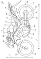
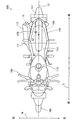
図1は本発明の一実施の形態に係る自動二輪車を示す一方側面図であり、図2は図1の自動二輪車100を上方から見た平面図である。図1および図2では、自動二輪車100が路面に対して垂直に起立した状態が示される。図1には、自動二輪車100の前後方向Lおよび上下方向Zが矢印で示される。また、図2には、自動二輪車100の前後方向Lおよび幅方向Wが矢印で示される。
(1) Schematic Configuration of Motorcycle FIG. 1 is a side view showing a motorcycle according to an embodiment of the present invention, and FIG. 2 is a plan view of the
図1に示すように、自動二輪車100は車体フレーム1Xを備える。車体フレーム1Xは、メインフレーム1およびサブフレーム2を含む。メインフレーム1の後端にサブフレーム2が後方に延びるように取り付けられている。
As shown in FIG. 1, the
メインフレーム1の前端には、ヘッドパイプ103が設けられている。ヘッドパイプ103にフロントフォーク104が左右方向に揺動可能に設けられている。フロントフォーク104の下端に前輪105が回転可能に支持されている。ヘッドパイプ103の上端にはハンドル106が取り付けられている。
A
メインフレーム1の下端部近傍にはエンジン109が設けられる。エンジン109の吸気ポートに吸気管110の一端が取り付けられ、エンジン109の排気ポートに排気管111の一端が取り付けられる。排気管111の他端に、マフラー112が取り付けられる。
An
サブフレーム2はエンジン109の上部に位置する。エンジン109の上方の位置で燃料タンク113がサブフレーム2により支持される。燃料タンク113の後方の位置で、シート114がサブフレーム2により支持される。本例のシート114は、2人の乗員の2つの着座部が一体成形されたシートである。自動二輪車100を操作する乗員はシート114の前方部分に座ることができる。また、自動二輪車100を操作しない乗員はシート114の後方部分に座ることができる。
The
シート114の前方部分の下方にECU(Electronic Control Unit;電子制御ユニット)115が設けられる。ECU115は、例えばI/F(インターフェース)、CPU(中央演算処理装置)、ROM(リードオンリメモリ)、RAM(ランダムアクセスメモリ)およびタイマを含む。
An ECU (Electronic Control Unit) 115 is provided below the front portion of the
メインフレーム1の下部から後方へ延びるようにリアアーム107が設けられる。リアアーム107の前端部は、支持軸107sを介してメインフレーム1に取り付けられる。リアアーム107の後端部は、後輪108および後輪ドリブンスプロケット108Sを回転可能に保持する。後輪ドリブンスプロケット108SにはチェーンCHが取り付けられる。
A
リアアーム107は、図示しないサスペンションにより支持軸107sを中心として上下方向Zに揺動可能である。それにより、例えば凹凸がある路面の走行中にシート114と後輪108との間の距離が変化する。
The
側面視でシート114の上面よりも下の空間に自動二輪車100の傾斜状態を検出する傾斜角センサ10が設けられる。また、側面視でシート114の上面よりも下の空間のうち、シート114の前端よりも後方かつシート114の後端よりも前方の空間に本体支持部10が設けられる。
An
より具体的には、シート114の後方部分の下方に傾斜角センサ10が設けられる。また、傾斜角センサ10は、後輪108の前端部分R1よりも後方に配置される。さらに、図2に示すように、垂直に起立した自動二輪車100を上方から見た場合に、傾斜角センサ10が自動二輪車100の車両中心線L1に重ならないように配置される。車両中心線L1は、自動二輪車100の前後方向Lに延びるとともに幅方向Wにおける後輪108の中心部分を通る。本例では、傾斜角センサ10は、車両中心線L1の右側に位置する。この場合、傾斜角センサ10と後輪108とが干渉することを防止しつつシート114の位置が高くなることを防止することができ、またはシート114の位置を低く抑えることができる。
More specifically, the
また、傾斜角センサ10は、前後方向Lにおいて後輪108の最上端部分R2よりも後方に位置するように配置される。自動二輪車100を操作する乗員が座るシート114の前方部分は、前後方向Lにおいて後輪108の最上端部分R2よりも前方に位置する。この場合、傾斜角センサ10はシート114の前方部分よりも後方に位置する。それにより、シート114の前方部分の高さを低くすることができる。その結果、自動二輪車100の停止時に、自動二輪車100を操作する乗員が足を地面に着けやすくなる。
Further, the
図2には、シート114のシート中心線L2が示される。シート中心線L2は、前後方向Lにおけるシート114の中心部分で幅方向Wに延びる。前後方向Lにおいて、シート114の中心部分は、後輪108の前端部分R1よりも後方に位置する。この場合、シート114と後輪108との間の間隔が狭くなりやすい。また、後輪108が上下方向Zに揺動可能な空間を確保するために、シート114の位置が高くなりやすい。このような場合でも、傾斜角センサ10が車両中心線L1に重ならないように配置されるので、シート114の位置が高くなりすぎることが防止される。
FIG. 2 shows a sheet center line L2 of the
傾斜角センサ10はサブフレーム2に取り付けられることにより固定される。傾斜角センサ10のサブフレーム2への取り付け構造の詳細は後述する。
The
傾斜角センサ10の出力信号はECU115に与えられる。ECU115は、傾斜角センサ10の出力信号に基づいて自動二輪車100の傾斜状態を判定する。具体的には、ECU115は、自動二輪車100の車両中心面が、前後方向Lに平行な鉛直面に対して予め定められた角度よりも大きく傾斜したか否かを判定する。自動二輪車100の車両中心面とは、自動二輪車100の車両中心線L1を含みかつ後輪108の幅方向Wの中心部分を通る面をいう。ECU115は、エンジン109の動作時に自動二輪車100の車両中心面が上記の鉛直面に対して予め定められた角度よりも大きく傾斜した場合に、自動二輪車100のエンジン109の動作を停止させる。
An output signal of the
(2)サブフレーム
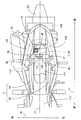
本実施の形態に係る自動二輪車100においては、シート114が後述するシートロック装置130によりサブフレーム2に取り付けおよび取り外し可能に構成される。図3は、図1のシート114が取り外された状態を示す自動二輪車100の一部拡大平面図である。図3では、サブフレーム2に取り付けられた状態のシート114が点線で示される。
(2) Subframe In the
図3に示すように、本実施の形態では、サブフレーム2は、一対のフレーム管20を含む。垂直に起立した自動二輪車100を上方から見た場合に、一対のフレーム管20は、車両中心線L1を挟んで互いに離間するように前後方向Lに延びる。一対のフレーム管20はそれぞれ鋼により形成される。
As shown in FIG. 3, in the present embodiment, the
一対のフレーム管20のうち一方のフレーム管20に、傾斜角センサ10をサブフレーム2に固定するための固定部材30が設けられている。固定部材30は、鋼により形成され、溶接により一方のフレーム管20に接合されている。固定部材30は、一対のフレーム管20の間で、一方のフレーム管20から他方のフレーム管20に向かって突出するように設けられる。
One
センサカバー40で覆われた傾斜角センサ10が固定部材30に取り付けられる。この場合、垂直に起立した自動二輪車100を上方から見た場合に、傾斜角センサ10が一対のフレーム管20の間に位置する状態で、傾斜角センサ10が固定部材30により固定される。それにより、傾斜角センサ10が一対のフレーム管20により保護され、傾斜角センサ10の損傷が防止される。固定部材30、センサカバー40および傾斜角センサ10の構成の詳細は後述する。
The
(3)サイドカバー
図1〜図3に示すように、一対のフレーム管20には、幅方向Wにおいて一対のフレーム管20の外側を覆うように一対のサイドカバー120が取り付けられる。また、図3に示すように、各サイドカバー120は、2本のボルトBLにより対応するフレーム管20に取り付けられる。一対のフレーム管20に一対のサイドカバー120が取り付けられた状態で、傾斜角センサ10は一対のサイドカバー120間の空間内に位置する。
(3) Side Cover As shown in FIGS. 1 to 3, a pair of side covers 120 are attached to the pair of
この場合、一対のサイドカバー120により、自動二輪車100の側方から飛散する雨水または泥水が傾斜角センサ10に付着することが防止される。また、自動二輪車100の側方から飛散する石が傾斜角センサ10に衝突することが防止される。それにより、傾斜角センサ10の損傷が防止される。
In this case, the pair of side covers 120 prevents rainwater or muddy water scattered from the sides of the
(4)カバー部材
図1および図3に示すように、一対のフレーム管20の下部には、後輪108の上方から後輪108の上部全体を覆うようにカバー部材121が取り付けられる。図3では、カバー部材121により覆われる後輪108が太い点線で示される。
(4) Cover Member As shown in FIGS. 1 and 3, a
本実施の形態では、カバー部材121が自動二輪車100の上下方向Zにおいて後輪108と傾斜角センサ10との間に配置される。それにより、後輪108から飛散する雨水または泥水が傾斜角センサ10に付着することが防止される。また、後輪108から飛散する石が傾斜角センサ10に衝突することが防止される。それにより、傾斜角センサ10の損傷が防止される。
In the present embodiment,
(5)シートロック装置
図3に示すように、前後方向Lにおいてサブフレーム2の中心部分よりもやや後方の位置に長尺状の支持板21が設けられる。支持板21は幅方向Wに延びるように配置される。支持板21は鋼により形成される。支持板21の一端および他端は一対のフレーム管20にそれぞれ溶接により接合される。支持板21の略中央部には矩形の切り欠き部131が形成されている。支持板21の切り欠き部131にシートロック装置130が取り付けられる。
(5) Seat Lock Device As shown in FIG. 3, a
シート114の下面(乗員の着座面と反対側の面)には、シートロックバー114Fが設けられている。シートロックバー114Fは、例えば略U字型に加工された棒状部材であり、シート114の幅方向Wにおける中心部分に設けられる。
A
シート114をサブフレーム2に取り付ける際には、シートロックバー114Fがシートロック装置130に重なるように、乗員がシート114をサブフレーム2上に配置する。この状態で、乗員がシート114を下方に押圧する。それにより、シートロック装置130がシートロックバー114Fを固定する。
When attaching the
一方、シート114をサブフレーム2から取り外す際には、乗員が図示しないキー孔に自動二輪車100のキーを差し込み、キーを操作する。それにより、シートロック装置130がシートロックバー114Fの固定状態を解除する。なお、シートロックバー114Fの固定状態を解除するためのキー孔は、例えばカバー部材121の一部に設けられる。
On the other hand, when removing the
本実施の形態では、傾斜角センサ10は、シート114がサブフレーム2に取り付けられた状態で、シートロック装置130よりも後方でかつシートロックバー114Fの側方に配置される。
In the present embodiment, the
この場合、シートロックバー114Fがシートロック装置130により固定された状態で、傾斜角センサ10とシートロックバー114Fとが干渉することが防止される。それにより、シート114の下部の空間を有効に利用することにより、シート114の上面の位置を高くすることなく種々のタイプの傾斜角センサ10を設けることが可能となる。
In this case, the
(6)固定部材の詳細
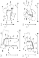
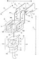
図4(a)は、フレーム管20に接合された固定部材30を上方から見た平面図である。図4(b)は、フレーム管20に接合された固定部材30を自動二輪車100の側方から見た側面図である。図4(c)は、フレーム管20に接合された固定部材30を自動二輪車100の後方から見た背面図である。図4(d)は、フレーム管20に接合された固定部材30を自動二輪車100の前方から見た正面図である。図4(a)〜(d)では、フレーム管20が点線で示される。また、前後方向L、幅方向Wおよび上下方向Zが矢印で示される。
(6) Details of Fixing Member FIG. 4A is a plan view of the fixing
固定部材30は所定の形状に加工された1枚の鋼板を折り曲げることにより作製される。図4(a)〜(d)に示すように、固定部材30は、前方板部31、下方板部32および後方板部33からなる。
The fixing
前方板部31は、固定部材30が一方のフレーム管20に接合された状態で上下方向Zおよび幅方向Wに平行になるように形成される。また、前方板部31は、他方のフレーム管20に向かって延びるように形成される。
The
前方板部31と同様に、後方板部33は、固定部材30が一方のフレーム管20に接合された状態で上下方向Zおよび幅方向Wに平行になるように形成される。また、後方板部33は、他方のフレーム管20に向かって延びるように形成される。
Similar to the
前方板部31および後方板部33は、前後方向Lに間隔をあけて一方のフレーム管20に接合される。それにより、前方板部31と後方板部33との間には、後述するように傾斜角センサ10を挿入可能な挿入部30Iが形成される。
The
下方板部32は、前方板部31の下端部の一部と後方板部33の下端部の一部とを繋ぐように形成される。下方板部32は、固定部材30が一方のフレーム管20に接合された状態でフレーム管20の下端部の一部領域に接するように形成された接合用側部32wを有する。
The
図4(c)に示すように、後方板部33の上端のうちフレーム管20から一定長さの部分は、残りの部分よりも高く形成される。それにより、後方板部33の上端に段差部33sが形成される。また、後方板部33の先端には、上方および下方に突出する突出部33pが形成される。
As shown in FIG. 4C, a portion of the upper end of the
図4(d)に示すように、前方板部31の下端のうちフレーム管20から一定長さの部分は、残りの部分よりも低く形成される。それにより、前方板部31の下端に段差部31sが形成される。また、前方板部31の先端には、上方および下方に突出する突出部31pが形成される。
As shown in FIG. 4D, a portion of the lower end of the
図4(a)〜(d)に示すように、一方のフレーム管20における固定部材30との接合部分は円形断面を有する。フレーム管20への固定部材30の接合時には、前方板部31の端部の一部31wが溶接によりフレーム管20の側部に接合される。また、後方板部33の端部の一部33wが溶接によりフレーム管20の側部に接合される。さらに、下方板部32の接合用側部32wの上面が溶接によりフレーム管20の下部に接合される。
As shown in FIGS. 4A to 4D, the joint portion of one
この場合、固定部材30は、フレーム管20の周方向の離間した複数の箇所に溶接により強固に固定される。それにより、固定部材30がフレーム管20に接合された状態でフレーム管20の周方向に沿って固定部材30に外力が与えられた場合に、固定部材30が一方のフレーム管20から外れることが防止される。
In this case, the fixing
特に、本実施の形態では、一方のフレーム管20における下方板部32の溶接部分の面積が、一方のフレーム管20における前方板部31および後方板部33の溶接部分の面積に比べて大きい。
In particular, in the present embodiment, the area of the welded portion of the
この場合、前方板部31および後方板部33に比べて、下方板部32がより強固に一方のフレーム管20に固定される。それにより、固定部材30に上方から下方へ力が加わった場合でも、固定部材30が一方のフレーム管20から外れることが確実に防止される。
In this case, the
上記のように、固定部材30が一方のフレーム管20に強固に固定される。それにより、固定部材30の挿入部30Iに傾斜角センサ10が設けられる場合に、固定部材30が一方のフレーム管20から外れることに起因する傾斜角センサ10の位置ずれの発生が防止される。その結果、傾斜角センサ10の位置ずれによる検出精度の低下が防止される。
As described above, the fixing
(7)傾斜角センサおよびセンサカバーの詳細
図5は、図3の傾斜角センサ10、センサカバー40、および固定部材30の一部を示す外観斜視図である。
(7) Details of Inclination Angle Sensor and Sensor Cover FIG. 5 is an external perspective view showing a part of the
まず、傾斜角センサ10の構成について説明する。図5に示すように、傾斜角センサ10は、本体部10Aおよび配線部10Bからなる。本体部10Aは、ケーシング11、回転軸12、振り子部材13、磁性体14および検出素子15を含む。ケーシング11は上面10tおよび下面10bを含む。ケーシング11は、回転軸12、振り子部材13、磁性体14および検出素子15を収容する。
First, the configuration of the
以下の説明において、傾斜角センサ10が自動二輪車100に取り付けられた状態を仮定した場合に、自動二輪車100の前方に向かうケーシング11の部分をセンサ前方部分SFと呼び、自動二輪車100の後方に向かうケーシング11の部分をセンサ後方部分SBと呼ぶ。傾斜角センサ10においても自動二輪車100と同様に前後方向L、幅方向Wおよび上下方向Zが定義される。
In the following description, when it is assumed that the
ケーシング11内では、傾斜角センサ10の前後方向Lに延びるように回転軸12が設けられる。回転軸12には、略半円形状を有する振り子部材13が揺動可能に取り付けられる。
In the
振り子部材13は、例えば絶縁性の樹脂材料により形成される。幅方向Wにおける振り子部材13の両端部近傍の領域にそれぞれ磁性体14が取り付けられる。磁性体14としては、例えば磁石が用いられる。
The
上下方向Zにおいて、振り子部材13の下方に検出素子15が設けられる。検出素子15は、磁性体14により発生する磁界を検出可能な磁気センサであり、例えばホール素子が用いられる。
In the vertical direction Z, the
ケーシング11の下面10bに配線部10Bが接続される。それにより、検出素子15が配線部10Bから下方に延びる配線19に接続される。
The
上記の傾斜角センサ10が自動二輪車100に取り付けられる。この場合、振り子部材13は、幅方向Wおよび上下方向Zを含む面内で揺動可能である。そのため、走行時に自動二輪車100が傾斜した場合、振り子部材13は検出素子15に対して相対的に揺動する。検出素子15は、磁性体14により発生する磁界を検出し、検出結果を図1のECU115に出力する。
The
次に、センサカバー40の構成について説明する。センサカバー40は、略立方体形状を有し、例えばゴムにより形成される。センサカバー40の中央部には、上下方向Zに延びるセンサ挿入孔40Hが設けられている。センサ挿入孔40Hは、傾斜角センサ10の本体部10Aが挿入可能に形成される。
Next, the configuration of the
また、センサカバー40は、センサ挿入孔40Hを挟むように幅方向Wに平行な2つの支持部41,42が形成されている。2つの支持部41,42の各々には、上下方向Zに延びかつ幅方向Wに貫通するスリット40Sが形成されている。
Further, the
傾斜角センサ10は、以下のようにしてサブフレーム2のフレーム管20に取り付けられる。まず、図5に太い矢印AR1で示すように、上下方向Zに沿って傾斜角センサ10がセンサカバー40のセンサ挿入孔40Hに挿入される。
The
次に、図5に太い矢印AR2で示すように、幅方向Wに沿って傾斜角センサ10が固定部材30の挿入部30Iに挿入される。このとき、図5に太い矢印AR3で示すように、センサカバー40の2つのスリット40Sにそれぞれ固定部材30の前方板部31および後方板部33が挿入される。
Next, the
これにより、傾斜角センサ10の本体部10Aがセンサカバー40により保護されつつ固定部材30の前方板部31と後方板部33との間で確実に固定される。
Accordingly, the
上記のように、本実施の形態では、センサカバー40への傾斜角センサ10の本体部10Aの挿入方向(上下方向Z)と固定部材30の挿入部30Iへの傾斜角センサ10の挿入方向(幅方向W)とが交差する。それにより、フレーム管20への傾斜角センサ10の取り付け時に、センサカバー40のセンサ挿入孔40Hから傾斜角センサ10の本体部10Aが抜け出ることが防止される。
As described above, in the present embodiment, the insertion direction (vertical direction Z) of the
上記のように、傾斜角センサ10がフレーム管20に取り付けられた状態で、自動二輪車100が傾斜する。この場合、自動二輪車100の傾斜状態に応じて振り子部材13が幅方向Wおよび上下方向Zを含む面内で揺動する。振り子部材13が揺動する方向は、鋼製の固定部材30の前方板部31および後方板部33が延びる方向に平行である。したがって、振り子部材13の揺動時に、振り子部材13に設けられる磁性体14と前方板部31との距離および磁性体14と後方板部33との距離が変動しない。その結果、検出素子15により検出される磁性体14の幅方向Wの位置に基づいて、自動二輪車100の傾斜状態が高い精度で検出される。
As described above, the
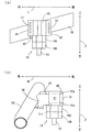
図6(a)はフレーム管20に取り付けられた傾斜角センサ10を自動二輪車100の一側方から見た側面図であり、図6(b)はフレーム管20に取り付けられた傾斜角センサ10を自動二輪車100の前方から見た側面図である。
6A is a side view of the
図6(a)に示すように、本実施の形態では、側面視において、傾斜角センサ10の本体部10Aは、固定部材30が接合されたフレーム管20の部分の下面よりも下方に位置する部分を有する。
As shown in FIG. 6A, in the present embodiment, the
このように、傾斜角センサ10においては、本体部10Aと配線部10Bとが上下方向Zに並びかつ本体部10Aの一部がフレーム管20の下方に位置する。この場合においても、垂直に起立した自動二輪車100を上方から見た場合に、傾斜角センサ10が車両中心線L1に重ならないように配置されるので、シート114の位置が高くなることを防止することができ、またはシート114の位置を低く抑えることができる。
As described above, in the
図6(b)に示すように、傾斜角センサ10がフレーム管20に取り付けられた状態で、センサカバー40の一方の支持部41は、幅方向Wにおいて前方板部31の2つの突出部31pと段差部31sとの間に位置する。この場合、段差部31sおよび2つの突出部31pはセンサカバー40が幅方向Wに移動することを規制する規制部として機能する。
As shown in FIG. 6B, in the state where the
同様に、傾斜角センサ10がフレーム管20に取り付けられた状態で、センサカバー40の他方の支持部42は、幅方向Wにおいて後方板部33(図4(c))の2つの突出部33pと段差部33s(図4(c))との間に位置する。この場合、段差部33sおよび2つの突出部33pはセンサカバー40が幅方向Wに移動することを規制する規制部として機能する。
Similarly, in the state in which the
これらより、傾斜角センサ10が幅方向Wへ移動しないので、傾斜角センサ10と鋼製のフレーム管20との間の距離が変化することが防止される。それにより、自動二輪車100の傾斜状態の検出精度の低下が抑制される。
Accordingly, since the
(8)効果
後輪108の幅方向Wの中心での外周部の直径は、後輪108の幅方向Wの中心以外の部分での外周部の直径に比べて大きい。そのため、垂直に起立した自動二輪車100を上方から見た場合に、傾斜角センサ10が車両中心線L1に重なるように配置されると、傾斜角センサ10が後輪108と干渉しやすい。
(8) Effect The diameter of the outer peripheral portion at the center of the
これに対して、本実施の形態に係る自動二輪車100においては、垂直に起立した自動二輪車100を上方から見た場合に、傾斜角センサ10が車両中心線L1に重ならないように配置される。それにより、傾斜角センサ10が後輪108の幅方向Wの中心部分と干渉することを防止することができる。また、上下方向Zに大きなサイズを有する傾斜角センサ10を用いた場合でも、シート114の位置が高くなることを防止することができ、またはシート114の位置を低く抑えることができる。したがって、自動二輪車100の停止時に乗員が足を地面に着けやすくなる。
On the other hand, in the
その結果、シート114の高さを低く保ちつつ種々のタイプの傾斜角センサ10を設けることが可能となる。
As a result, various types of
(9)他の実施の形態
上記実施の形態においては、傾斜角センサ10として自動二輪車100の傾斜状態を検出する本体部10Aと配線部10Bとが上下方向Zに並ぶ縦型の傾斜角センサが用いられる。これに限らず、傾斜角センサ10としては、本体部10Aと配線部10Bとが前後方向Lまたは幅方向Wに並ぶ横型の傾斜角センサ10が用いられてもよい。この場合、自動二輪車100の上下方向Zにおける傾斜角センサ10のサイズが小さくなるので、シートの高さをさらに低く保つことができる。
(9) Other Embodiments In the above-described embodiment, a vertical inclination angle sensor in which the
上記実施の形態に係る自動二輪車100はシート114を備える。これに限らず、自動二輪車100は、シート114に代えて、自動二輪車100を操作する乗員用のシートと自動二輪車100を操作しない乗員用のシートとを個別に備えてもよい。この場合、自動二輪車100の前後方向Lにおいて、自動二輪車100を操作する乗員用のシートの後端部は、図1および図2の後輪108の前端部分R1よりも後方に位置してもよい。また、自動二輪車100の前後方向Lにおいて、自動二輪車100を操作しない乗員用のシートの前端部は、図1および図2の後輪108の前端部分R1よりも後方に位置してもよい。
The
または、自動二輪車100は、シート114に代えて、自動二輪車100を操作する乗員用のシートのみを備えてもよい。この場合、前後方向Lにおいて、自動二輪車100を操作する乗員用のシートの後端部は、図1および図2の後輪108の前端部分R1よりも後方に位置してもよい。
Alternatively, the
上記実施の形態においては、サブフレーム2の一方のフレーム管20に固定部材30が溶接により接合される。これに限らず、固定部材30は、例えばねじを用いてフレーム管20に接続されてもよい。この場合、固定部材30を簡単にフレーム管20に取り付けることができる。また、固定部材30を簡単にフレーム管20から取り外すことができる。
In the above embodiment, the fixing
上記実施の形態においては、傾斜角センサ10の振り子部材13の両端部近傍の領域にそれぞれ磁性体14が取り付けられるが、振り子部材13に取り付けられる磁性体14の数および位置は上記に限定されない。例えば、振り子部材13の外周部の中心位置に1つの磁性体14のみが設けられてもよい。
In the above-described embodiment, the
上記実施の形態は、本発明を自動二輪車に適用した例であるが、これに限らず、自動三輪車もしくはATV(All Terrain Vehicle;不整地走行車両)等の他の鞍乗型車両に本発明を適用してもよい。 The above embodiment is an example in which the present invention is applied to a motorcycle. However, the present invention is not limited to this, and the present invention is applied to other straddle-type vehicles such as a motor tricycle or an ATV (All Terrain Vehicle). You may apply.
(10)請求項の各構成要素と実施の形態の各部との対応関係
以下、請求項の各構成要素と実施の形態の各構成要素との対応の例について説明するが、本発明は下記の例に限定されない。
(10) Correspondence between each component of claim and each part of embodiment The following describes an example of a correspondence between each component of the claim and each component of the embodiment. It is not limited to examples.
上記実施の形態においては、自動二輪車100が鞍乗型車両の例であり、後輪108が後輪の例であり、シート114がシートの例であり、サブフレーム2および一対のフレーム管20がシートフレームの例であり、車体フレーム1Xが車体フレームの例である。
In the above embodiment, the
また、リアアーム107が後輪支持部材の例であり、傾斜角センサ10が傾斜角センサの例であり、固定部材30が固定部材の例であり、車両中心線L1が車両中心線の例であり、一対のフレーム管20が一対のフレーム部材の例である。
The
また、一対のサイドカバー120が一対のサイドカバーの例であり、カバー部材121がカバー部材の例であり、振り子部材13が振り子部材の例であり、磁性体14が磁性体の例であり、検出素子15が検出素子の例である。
The pair of side covers 120 is an example of a pair of side covers, the
また、固定部材30における前方板部31の段差部31sおよび2つの突出部31pならびに後方板部33の段差部33sおよび2つの突出部33pが規制部の例である。
Further, the
また、シートロック装置130がシートロック装置の例であり、シートロックバー114Fが固定具の例であり、上面10tが上面の例であり、下面10bが下面の例であり、本体部10Aが本体部およびセンサ本体の例であり、配線部10Bが配線部の例である。
The
また、センサ挿入孔40Hが開口部の例であり、センサカバー40がセンサカバーの例であり、挿入部30Iが挿入部の例であり、前方板部31および後方板部33が一対の板状部材の例であり、スリット40Sがスリットの例である。
The
また、前方板部31および後方板部33が側方部分の例であり、下方板部32が下方部分の例である。
The
請求項の各構成要素として、請求項に記載されている構成または機能を有する他の種々の構成要素を用いることもできる。 As each constituent element in the claims, various other constituent elements having configurations or functions described in the claims can be used.
本発明は、傾斜角センサを備える車両に有効に利用することができる。 The present invention can be effectively used for a vehicle including an inclination angle sensor.
1 メインフレーム
1X 車体フレーム
2 サブフレーム
10 傾斜角センサ
10A 本体部
10B 配線部
10b 下面
10t 上面
13 振り子部材
14 磁性体
15 検出素子
19 配線
20 フレーム管
21 支持板
30 固定部材
30I 挿入部
31 前方板部
31p 突出部
31s 段差部
32 下方板部
32L 接合用側辺
33 後方板部
33p 突出部
33s 段差部
40 センサカバー
40H センサ挿入孔
40S スリット
41,42 支持部
100 自動二輪車
103 ヘッドパイプ
104 フロントフォーク
105 前輪
106 ハンドル
107 リアアーム
107s 支持軸
108 後輪
108S 後輪ドリブンスプロケット
109 エンジン
110 吸気管
111 排気管
112 マフラー
113 燃料タンク
114 シート
114F シートロックバー
115 ECU
120 サイドカバー
121 カバー部材
130 シートロック装置
131 切り欠き部
BL ボルト
CH チェーン
L 前後方向
L1 車両中心線
L2 シート中心線
R1 前端部分
R2 最上端部分
SF センサ前方部分
SB センサ後方部分
W 幅方向
Z 上下方向
DESCRIPTION OF SYMBOLS 1
120
Claims (15)
後輪と、
乗員が座るシートと、
前記車両の前後方向に延びるように設けられ、前記シートを支持するシートフレームを含む車体フレームと、
前記後輪を前記車体フレームに揺動可能に支持する後輪支持部材と、
前記車両の傾斜状態を検出する傾斜角センサと、
前記傾斜角センサを前記シートの下方に固定する固定部材とを備え、
前記シートフレームの少なくとも一部は前記車両の上下方向における前記後輪と前記シートとの間に配置され、
前記傾斜角センサは、平面視において前記後輪の幅方向の中心を通る車両中心線に重ならないように配置される、鞍乗型車両。 A straddle-type vehicle,
The rear wheel,
A seat on which the occupant sits,
A vehicle body frame including a seat frame provided to extend in the front-rear direction of the vehicle and supporting the seat;
A rear wheel support member for swingably supporting the rear wheel on the body frame;
An inclination angle sensor for detecting an inclination state of the vehicle;
A fixing member for fixing the tilt angle sensor below the seat,
At least a part of the seat frame is disposed between the rear wheel and the seat in the vertical direction of the vehicle,
The tilt angle sensor is a straddle-type vehicle that is disposed so as not to overlap a vehicle center line passing through a center in a width direction of the rear wheel in plan view.
前記固定部材は、前記一対のフレーム部材間に前記傾斜角センサを支持するように前記一対のフレーム部材のうち一方のフレーム部材に取り付けられる、請求項1〜3のいずれか一項に記載の鞍乗型車両。 The seat frame includes a pair of frame members extending in the front-rear direction of the vehicle so as to be separated from each other across the vehicle center line in plan view,
The scissors according to any one of claims 1 to 3, wherein the fixing member is attached to one frame member of the pair of frame members so as to support the inclination angle sensor between the pair of frame members. Ride type vehicle.
前記一対のサイドカバーは、前記傾斜角センサの外側を覆うように設けられる、請求項4記載の鞍乗型車両。 A pair of side covers provided to cover the outside of the pair of frame members in the width direction of the vehicle;
The straddle-type vehicle according to claim 4, wherein the pair of side covers are provided so as to cover an outside of the inclination angle sensor.
前記カバー部材は、平面視において前記車両中心線と重なるように設けられ、
前記傾斜角センサは、前記車両の上下方向において前記シートと前記カバー部材との間に配置される、請求項1〜5のいずれか一項に記載の鞍乗型車両。 A cover member disposed between the rear wheel and the seat in the vertical direction of the vehicle;
The cover member is provided so as to overlap the vehicle center line in plan view,
The straddle-type vehicle according to any one of claims 1 to 5, wherein the inclination angle sensor is disposed between the seat and the cover member in a vertical direction of the vehicle.
前記傾斜角センサは、
前記車両の幅方向および上下方向を含む面内で揺動可能に設けられる振り子部材と、
前記振り子部材に設けられる磁性体と、
前記磁性体の位置を検出する検出素子とを含む、請求項1〜7のいずれか一項に記載の鞍乗型車両。 The fixing member is formed of steel and is formed to extend in the width direction of the vehicle.
The tilt angle sensor is
A pendulum member provided so as to be swingable in a plane including a width direction and a vertical direction of the vehicle;
A magnetic body provided on the pendulum member;
The straddle-type vehicle according to any one of claims 1 to 7, further comprising a detection element that detects a position of the magnetic body.
前記固定部材は、前記傾斜角センサの前記車両の幅方向への移動を規制する規制部を有する、請求項8記載の鞍乗型車両。 The seat frame is formed of steel;
The straddle-type vehicle according to claim 8, wherein the fixing member includes a restricting portion that restricts movement of the tilt angle sensor in a width direction of the vehicle.
前記シートの幅方向の中心に設けられ、前記シートロック装置に着脱可能に固定される固定具とをさらに備え、
前記傾斜角センサは、前記シートロック装置よりも後方でかつ前記固定具の側方に配置される、請求項1〜9のいずれか一項に記載の鞍乗型車両。 A seat lock device provided in the seat frame so as to extend in the width direction of the vehicle;
A fixing tool provided at the center in the width direction of the seat and detachably fixed to the seat lock device;
The straddle-type vehicle according to any one of claims 1 to 9, wherein the inclination angle sensor is disposed behind the seat lock device and on a side of the fixture.
センサ本体と、
前記センサ本体を挿入可能な開口部を有しかつ前記センサ本体を覆うセンサカバーとを含み、
前記固定部材は、前記センサ本体を挿入可能な挿入部を有し、
前記センサカバーへのセンサ本体の挿入方向と前記固定部材の前記挿入部への前記センサ本体の挿入方向とが交差する、請求項1〜10のいずれか一項に記載の鞍乗型車両。 The tilt angle sensor is
A sensor body;
A sensor cover having an opening into which the sensor body can be inserted and covering the sensor body,
The fixing member has an insertion part into which the sensor body can be inserted,
The straddle-type vehicle according to any one of claims 1 to 10, wherein an insertion direction of the sensor main body into the sensor cover intersects with an insertion direction of the sensor main body into the insertion portion of the fixing member.
前記センサカバーは、上下方向に延びる複数のスリットを有し、
前記センサカバーの前記開口部に前記センサ本体が上下方向に挿入された状態で前記センサ本体が前記一対の板状部材間に前記車両の幅方向に挿入されるとともに前記一対の板状部材が前記センサカバーの前記複数のスリットに挿入される、請求項11記載の鞍乗型車両。 The fixing member includes a pair of plate-like members that extend in the width direction of the vehicle and are attached to the seat frame with an interval in the front-rear direction of the vehicle, and the insertion portion is formed between the pair of plate-like members. And
The sensor cover has a plurality of slits extending in the vertical direction,
The sensor body is inserted in the width direction of the vehicle between the pair of plate-like members in a state where the sensor body is vertically inserted into the opening of the sensor cover, and the pair of plate-like members are The straddle-type vehicle according to claim 11, wherein the straddle-type vehicle is inserted into the plurality of slits of the sensor cover.
前記固定部材は、前記シートフレームの円形断面部分の周方向の離間した複数の箇所に溶接により接続される、請求項1〜12のいずれか一項に記載の鞍乗型車両。 The seat frame has a circular cross section;
The straddle-type vehicle according to any one of claims 1 to 12, wherein the fixing member is connected by welding to a plurality of circumferentially spaced portions of the circular cross-section portion of the seat frame.
前記シートフレームの側方に位置しかつ前記シートフレームの側部に溶接される側方部分と、
前記シートフレームの下方に位置しかつ前記シートフレームの下部に溶接される下方部分とを有する、請求項1〜13のいずれか一項に記載の鞍乗型車両。 The fixing member is
A side portion located on the side of the seat frame and welded to the side of the seat frame;
The straddle-type vehicle according to any one of claims 1 to 13, further comprising a lower portion positioned below the seat frame and welded to a lower portion of the seat frame.
Priority Applications (6)
| Application Number | Priority Date | Filing Date | Title |
|---|---|---|---|
| JP2012193180A JP2014046880A (en) | 2012-09-03 | 2012-09-03 | Saddle-riding type vehicle |
| BR102013020910-4A BR102013020910B1 (en) | 2012-09-03 | 2013-08-15 | saddle-mounted motor vehicle |
| MYPI2013701530A MY185424A (en) | 2012-09-03 | 2013-08-29 | A saddle-straddling type motor vehicle |
| EP13182626.5A EP2703262B1 (en) | 2012-09-03 | 2013-09-02 | A saddle-straddling type motor vehicle |
| ES13182626.5T ES2586702T3 (en) | 2012-09-03 | 2013-09-02 | Straddle type motor vehicle |
| CO13208595A CO7210071A1 (en) | 2012-09-03 | 2013-09-03 | A motor vehicle of the astride type |
Applications Claiming Priority (1)
| Application Number | Priority Date | Filing Date | Title |
|---|---|---|---|
| JP2012193180A JP2014046880A (en) | 2012-09-03 | 2012-09-03 | Saddle-riding type vehicle |
Publications (1)
| Publication Number | Publication Date |
|---|---|
| JP2014046880A true JP2014046880A (en) | 2014-03-17 |
Family
ID=49080788
Family Applications (1)
| Application Number | Title | Priority Date | Filing Date |
|---|---|---|---|
| JP2012193180A Pending JP2014046880A (en) | 2012-09-03 | 2012-09-03 | Saddle-riding type vehicle |
Country Status (6)
| Country | Link |
|---|---|
| EP (1) | EP2703262B1 (en) |
| JP (1) | JP2014046880A (en) |
| BR (1) | BR102013020910B1 (en) |
| CO (1) | CO7210071A1 (en) |
| ES (1) | ES2586702T3 (en) |
| MY (1) | MY185424A (en) |
Cited By (1)
| Publication number | Priority date | Publication date | Assignee | Title |
|---|---|---|---|---|
| US12403970B2 (en) | 2020-05-04 | 2025-09-02 | David Watson | Device for adjusting a seat position of a bicycle seat |
Families Citing this family (2)
| Publication number | Priority date | Publication date | Assignee | Title |
|---|---|---|---|---|
| WO2025233958A1 (en) * | 2024-05-10 | 2025-11-13 | Tvs Motor Company Limited | A vehicle with control unit in front portion |
| TWI900368B (en) * | 2024-12-12 | 2025-10-01 | 三陽工業股份有限公司 | Straddled vehicle |
Family Cites Families (3)
| Publication number | Priority date | Publication date | Assignee | Title |
|---|---|---|---|---|
| JP4475526B2 (en) * | 2005-02-22 | 2010-06-09 | 本田技研工業株式会社 | Tilt sensor mounting structure |
| WO2006111923A1 (en) * | 2005-04-18 | 2006-10-26 | Van Der Westhuizen Pieter Dani | Fairing assembly for a motorcycle |
| JP5310042B2 (en) * | 2009-02-03 | 2013-10-09 | スズキ株式会社 | Motorcycle article storage structure |
-
2012
- 2012-09-03 JP JP2012193180A patent/JP2014046880A/en active Pending
-
2013
- 2013-08-15 BR BR102013020910-4A patent/BR102013020910B1/en active IP Right Grant
- 2013-08-29 MY MYPI2013701530A patent/MY185424A/en unknown
- 2013-09-02 EP EP13182626.5A patent/EP2703262B1/en active Active
- 2013-09-02 ES ES13182626.5T patent/ES2586702T3/en active Active
- 2013-09-03 CO CO13208595A patent/CO7210071A1/en unknown
Cited By (1)
| Publication number | Priority date | Publication date | Assignee | Title |
|---|---|---|---|---|
| US12403970B2 (en) | 2020-05-04 | 2025-09-02 | David Watson | Device for adjusting a seat position of a bicycle seat |
Also Published As
| Publication number | Publication date |
|---|---|
| BR102013020910A2 (en) | 2015-06-16 |
| BR102013020910B1 (en) | 2020-07-28 |
| CO7210071A1 (en) | 2015-03-09 |
| EP2703262B1 (en) | 2016-07-13 |
| ES2586702T3 (en) | 2016-10-18 |
| EP2703262A1 (en) | 2014-03-05 |
| MY185424A (en) | 2021-05-19 |
Similar Documents
| Publication | Publication Date | Title |
|---|---|---|
| JP6636130B2 (en) | Motorcycle | |
| JP5793932B2 (en) | Saddle riding vehicle | |
| JP2005178420A (en) | Saddle-type vehicle for running on rough terrain | |
| JP4719560B2 (en) | Motorcycle | |
| JP2007131030A (en) | Saddle riding vehicle | |
| ES2460924T3 (en) | Straddle Vehicle | |
| JP4559197B2 (en) | Grab rail mounting structure for motorcycles | |
| WO2019167220A1 (en) | Saddle-type vehicle | |
| JP2014046880A (en) | Saddle-riding type vehicle | |
| JP6547064B2 (en) | Straddle type vehicle | |
| JP2009090758A (en) | Motorcycle | |
| CN112351935B (en) | Oxygen sensor configuration structure of motorcycle | |
| BR102012024555A2 (en) | motorcycle | |
| JP2009161013A (en) | Motorcycle | |
| JP2011063068A (en) | Front structure in saddle riding type vehicle | |
| JP2009107566A (en) | Motorcycle | |
| JP2016182926A (en) | Motorcycle | |
| WO2012057159A1 (en) | Automatic two-wheeled vehicle | |
| JP4503519B2 (en) | Vehicle fuel tank arrangement structure | |
| JP4443400B2 (en) | Motorcycle frame | |
| JP5869398B2 (en) | Mounting structure of inclination angle detecting means in motorcycle | |
| CN220662720U (en) | Saddle-ride type vehicle | |
| JP4870198B2 (en) | Motorcycle frame | |
| JP6682410B2 (en) | Cooling water reservoir tank for saddle type vehicles | |
| JP5302805B2 (en) | Tilt sensor arrangement structure |