JP2014046855A - Webbing take-up device - Google Patents
Webbing take-up device Download PDFInfo
- Publication number
- JP2014046855A JP2014046855A JP2012192275A JP2012192275A JP2014046855A JP 2014046855 A JP2014046855 A JP 2014046855A JP 2012192275 A JP2012192275 A JP 2012192275A JP 2012192275 A JP2012192275 A JP 2012192275A JP 2014046855 A JP2014046855 A JP 2014046855A
- Authority
- JP
- Japan
- Prior art keywords
- rotating body
- spool
- motor
- gear
- rotation
- Prior art date
- Legal status (The legal status is an assumption and is not a legal conclusion. Google has not performed a legal analysis and makes no representation as to the accuracy of the status listed.)
- Pending
Links
- 230000003068 static effect Effects 0.000 claims abstract description 13
- 238000004804 winding Methods 0.000 claims description 66
- 230000005540 biological transmission Effects 0.000 claims description 22
- 230000002093 peripheral effect Effects 0.000 abstract description 32
- 230000006835 compression Effects 0.000 abstract description 15
- 238000007906 compression Methods 0.000 abstract description 15
- 238000003466 welding Methods 0.000 abstract 4
- 230000008878 coupling Effects 0.000 description 8
- 238000010168 coupling process Methods 0.000 description 8
- 238000005859 coupling reaction Methods 0.000 description 8
- 230000000694 effects Effects 0.000 description 4
- 238000012806 monitoring device Methods 0.000 description 3
- 238000013459 approach Methods 0.000 description 2
- 230000015572 biosynthetic process Effects 0.000 description 2
- 101000666896 Homo sapiens V-type immunoglobulin domain-containing suppressor of T-cell activation Proteins 0.000 description 1
- 102100038282 V-type immunoglobulin domain-containing suppressor of T-cell activation Human genes 0.000 description 1
- 230000001133 acceleration Effects 0.000 description 1
- 230000004308 accommodation Effects 0.000 description 1
- 238000006243 chemical reaction Methods 0.000 description 1
- 230000000149 penetrating effect Effects 0.000 description 1
- 230000003014 reinforcing effect Effects 0.000 description 1
Images


Landscapes
- Automotive Seat Belt Assembly (AREA)
Abstract
Description
本発明は、車両のシートベルト装置を構成するウェビング巻取装置に係り、特に、モータの駆動力でスプールを回転させることが可能なウェビング巻取装置に関する。 The present invention relates to a webbing take-up device that constitutes a seat belt device of a vehicle, and more particularly to a webbing take-up device capable of rotating a spool by a driving force of a motor.
下記の特許文献1の図14にはモータの駆動力でスプール(特許文献1では「スピンドル」と称している)を回転させることができるウェビング巻取装置(特許文献1では「シートベルト装置」と称している)のトルクリミッタ機構が開示されている。このトルクリミッタ機構はモータ側回転体である大径側ギヤ(アクチュエータ側ギヤ)の内側にスプール側回転体である小径側ギヤ(スピンドル側ギヤ)が同軸的に設けられている。この大径側ギヤと小径側ギヤとの間には回転伝達部材であるリミットスプリング(弾性片)が設けられている。 FIG. 14 of Patent Document 1 below shows a webbing take-up device (referred to as “seat belt device” in Patent Document 1) that can rotate a spool (referred to as “spindle” in Patent Document 1) by the driving force of a motor. A torque limiter mechanism is disclosed. In this torque limiter mechanism, a small-diameter side gear (spindle side gear) that is a spool-side rotator is coaxially provided inside a large-diameter side gear (actuator-side gear) that is a motor-side rotator. A limit spring (elastic piece) that is a rotation transmission member is provided between the large-diameter side gear and the small-diameter side gear.
リミットスプリングはその一端が小径側ギヤの外周部にて開口したスリットに挿し込まれている。これに対して、リミットスプリングは他端には突部が形成されている。この突部に対応して大径側ギヤの内周部にはその周方向に連続した波状の凹凸が形成され、リミットスプリングの突部はこの波状の凹凸の何れかの凹部に入り込んでいる。 One end of the limit spring is inserted into a slit opened at the outer peripheral portion of the small-diameter side gear. On the other hand, the limit spring has a protrusion at the other end. Corresponding to this protrusion, a continuous wave-shaped unevenness is formed in the inner peripheral portion of the large-diameter side gear, and the protrusion of the limit spring enters one of the recesses of the wave-shaped unevenness.
モータの駆動力で大径側ギヤが回転すると、この回転力がリミットスプリングを介して小径側ギヤに伝わり、スプールを回転させる。また、スプールを巻取方向に回転させるためのモータの駆動力が大径側ギヤに伝えられている状態で、例えば、ウェビングが引っ張られて、スプールに引出方向の回転力が入力された場合に、大径側ギヤの回転力がリミットスプリングの付勢力(弾性力)を越えると、リミットスプリングに対して大径側ギヤが回転し、その際にリミットスプリングの突部が大径側ギヤの凹部から抜け出る。これにより、大径側ギヤが小径側ギヤに対して相対回転できる。 When the large-diameter side gear is rotated by the driving force of the motor, this rotational force is transmitted to the small-diameter side gear via the limit spring and rotates the spool. Also, when the driving force of the motor for rotating the spool in the winding direction is transmitted to the large-diameter side gear, for example, when the webbing is pulled and the rotational force in the pulling direction is input to the spool When the rotational force of the large-diameter side gear exceeds the biasing force (elastic force) of the limit spring, the large-diameter side gear rotates relative to the limit spring, and at this time, the protrusion of the limit spring becomes the concave portion of the large-diameter side gear. Get out of. Thereby, the large-diameter side gear can rotate relative to the small-diameter side gear.
ところで、大径側ギヤの凹部からリミットスプリングの突部から抜け出て、大径側ギヤの凸部を乗り越えた後に隣りの凹部にリミットスプリングの突部が入り込む際には、リミットスプリングの突部が入り込んだ凹部を弾性力で叩く。これにより、衝撃音が発生する。 By the way, when the protrusion of the limit spring enters the adjacent recess after getting out of the protrusion of the limit spring from the recess of the large diameter gear and overcoming the protrusion of the large diameter gear, the protrusion of the limit spring Strike the recessed part with the elastic force. Thereby, an impact sound is generated.
本発明は、上記事実を考慮して、スプール側回転体に対してモータ側回転体が相対回転する際に衝撃音が発生しない、又は、このような衝撃音の発生を抑制できるウェビング巻取装置を得ることが目的である。 In consideration of the above-described facts, the present invention provides a webbing take-up device that does not generate an impact sound when the motor-side rotating body rotates relative to the spool-side rotating body or can suppress the generation of such an impact sound. Is the purpose.
請求項1に記載の本発明に係るウェビング巻取装置は、ウェビングの長手方向基端側が係止されて、軸周りの一方の巻取方向に回転することで前記ウェビングを巻取るスプールと、前記スプールに対して一体的に設けられ或いは前記スプールに直接又は間接的に連結されて、所定方向への回転を前記スプールに伝えて前記スプールを前記巻取方向に回転させるスプール側回転体と、モータと、前記モータの駆動力が伝えられて前記所定方向へ回転するモータ側回転体と、前記モータ側回転体及び前記スプール側回転体のうちの一方の回転体に設けられて前記一方の回転体と共に回転し、且つ、前記一方の回転体の回転半径方向中央側への向き又は前記回転半径方向外方に沿った付勢力で前記モータ側回転体及び前記スプール側回転体のうちの他方の回転体に圧接して、前記他方の回転体との間の摩擦で前記モータ側回転体の回転を前記スプール側回転体に伝えると共に、前記スプール側回転体に対する前記モータ側回転体の前記所定方向への回転力が、前記他方の回転体との間で生ずる最大静止摩擦力を越えた場合に前記一方の回転体と共に前記他方の回転体に対して相対回転する回転伝達部材と、を備えている。 The webbing take-up device according to the first aspect of the present invention includes a spool that winds up the webbing by being locked in a longitudinal direction proximal end side of the webbing and rotating in one winding direction around an axis. A spool-side rotating body that is provided integrally with the spool or that is directly or indirectly connected to the spool, transmits rotation in a predetermined direction to the spool, and rotates the spool in the winding direction; and a motor A motor-side rotating body that is rotated in the predetermined direction by being transmitted with a driving force of the motor, and the one rotating body is provided on one of the motor-side rotating body and the spool-side rotating body. Of the motor-side rotating body and the spool-side rotating body with a biasing force along the direction toward the center of the rotational radius of the one rotary body or outward in the rotational radius direction. The rotation of the motor-side rotating body is transmitted to the spool-side rotating body by friction with the other rotating body, and the motor-side rotating body with respect to the spool-side rotating body is in contact with the other rotating body. A rotation transmitting member that rotates relative to the other rotating body together with the one rotating body when a rotational force in a predetermined direction exceeds a maximum static frictional force generated between the rotating body and the other rotating body; I have.
請求項1に記載の本発明に係るウェビング巻取装置では、スプール側回転体及びモータ側回転体のうちの一方の回転体には回転伝達部材が設けられる。回転伝達部材は、この一方の回転体の回転半径方向中央側への向き又は回転半径方向外方に沿った付勢力でスプール側回転体及びモータ側回転体のうちの他方の回転体に圧接しており、回転伝達部材と他方の回転体との間で生じる摩擦によって回転伝達部材と他方の回転体との間で回転を伝えることができ、これによってモータ側回転体からスプール側回転体へモータの駆動力(回転力)を伝えることができる。モータの駆動力がスプール側回転体に伝わって、スプール側回転体が所定方向へ回転することによってスプールが巻取方向に回転する。これによって、スプールにウェビングが巻き取られる。 In the webbing take-up device according to the first aspect of the present invention, a rotation transmission member is provided on one of the spool-side rotating body and the motor-side rotating body. The rotation transmitting member is in pressure contact with the other rotating body of the spool-side rotating body and the motor-side rotating body by an urging force along the direction toward the center of the rotating radius of the one rotating body or outward in the rotating radial direction. The rotation can be transmitted between the rotation transmitting member and the other rotating body by the friction generated between the rotation transmitting member and the other rotating body, whereby the motor is rotated from the motor side rotating body to the spool side rotating body. The driving force (rotational force) can be transmitted. The driving force of the motor is transmitted to the spool-side rotating body, and the spool-side rotating body rotates in a predetermined direction, whereby the spool rotates in the winding direction. As a result, the webbing is wound around the spool.
一方、例えば、直接又は間接的にスプール側回転体の所定方向への回転が規制され、又は、スプール側回転体に所定方向とは反対方向への回転力が付与された状態でモータ側回転体が所定方向へ回転すると、スプール側回転体に対してモータ側回転体が所定方向へ相対回転しようとする。この相対回転の回転力が回転伝達部材と他方の回転体との最大静止摩擦力を越えると、回転伝達部材と他方の回転体との間で滑りが生じ、これによって、スプール側回転体に対してモータ側回転体が所定方向へ相対回転する。 On the other hand, for example, rotation of the spool-side rotator in a predetermined direction is directly or indirectly restricted, or the motor-side rotator is applied with a rotational force in a direction opposite to the predetermined direction. When the motor rotates in a predetermined direction, the motor side rotating body tends to rotate relative to the spool side rotating body in the predetermined direction. When the rotational force of the relative rotation exceeds the maximum static frictional force between the rotation transmitting member and the other rotating body, slippage occurs between the rotation transmitting member and the other rotating body, thereby Thus, the motor side rotating body relatively rotates in a predetermined direction.
このように、本発明に係るウェビング巻取装置においてスプール側回転体に対してモータ側回転体が所定方向へ相対回転する際には、回転伝達部材と他方の回転体との間の摩擦力に抗した滑りが生じるだけであるので、回転伝達部材と他方の回転体との間で衝撃音が発生しない。 Thus, in the webbing take-up device according to the present invention, when the motor-side rotating body rotates relative to the spool-side rotating body in a predetermined direction, the frictional force between the rotation transmitting member and the other rotating body is reduced. Since only anti-slip occurs, no impact sound is generated between the rotation transmitting member and the other rotating body.
請求項2に記載の本発明に係るウェビング巻取装置は、請求項1に記載の本発明において、前記一方の回転体の回転中心周りに複数の前記回転伝達部材を設けている。 A webbing take-up device according to a second aspect of the present invention is the webbing take-up device according to the first aspect of the present invention, wherein a plurality of the rotation transmitting members are provided around the rotation center of the one rotating body.
請求項2に記載の本発明に係るウェビング巻取装置では、スプール側回転体及びモータ側回転体のうちの一方の回転体の回転中心周りに複数の回転伝達部材が設けられる。このように付勢力で他方の回転体に圧接する回転伝達部材が複数設けられることにより、スプール側回転体、モータ側回転体、及び複数の回転伝達部材の間の構造の安定化を図ることができる。 In the webbing take-up device according to the second aspect of the present invention, a plurality of rotation transmission members are provided around the rotation center of one of the spool side rotating body and the motor side rotating body. As described above, by providing a plurality of rotation transmitting members that press against the other rotating body by the urging force, it is possible to stabilize the structure between the spool-side rotating body, the motor-side rotating body, and the plurality of rotation transmitting members. it can.
請求項3に記載の本発明に係るウェビング巻取装置は、請求項2に記載の本発明において、前記一方の回転体の回転中心周りに一定角度毎に同じ大きさの付勢力で付勢された複数の前記回転伝達部材を設けている。 A webbing take-up device according to a third aspect of the present invention is the webbing take-up device according to the second aspect of the present invention, wherein the webbing take-up device according to the second aspect of the present invention is A plurality of the rotation transmitting members are provided.
請求項2に記載の本発明に係るウェビング巻取装置では、スプール側回転体及びモータ側回転体のうちの一方の回転体の回転中心周りに複数の回転伝達部材が一定角度毎に設けられ、しかも、これらの回転伝達部材は同じ大きさの付勢力で付勢される。このため、スプール側回転体、モータ側回転体、及び複数の回転伝達部材の間の構造を更に安定させることができる。 In the webbing take-up device according to the second aspect of the present invention, a plurality of rotation transmission members are provided at fixed angles around the rotation center of one of the spool-side rotating body and the motor-side rotating body, Moreover, these rotation transmission members are urged by the same urging force. For this reason, the structure between the spool side rotating body, the motor side rotating body, and the plurality of rotation transmitting members can be further stabilized.
請求項4に記載の本発明に係るウェビング巻取装置は、ウェビングの長手方向基端側が係止されて、軸周りの一方の巻取方向に回転することで前記ウェビングを巻取るスプールと、前記スプールに対して一体的に設けられ或いは前記スプールに直接又は間接的に連結されて、所定方向への回転を前記スプールに伝えて前記スプールを前記巻取方向に回転させるスプール側回転体と、モータと、前記モータの駆動力が伝えられて前記所定方向へ回転するモータ側回転体と、前記モータ側回転体及び前記スプール側回転体のうちの一方の回転体に設けられて前記一方の回転体と共に回転し、且つ、前記一方の回転体の軸方向に沿った付勢力で前記モータ側回転体及び前記スプール側回転体のうちの他方の回転体に圧接して、前記他方の回転体との間の摩擦で前記モータ側回転体の回転を前記スプール側回転体に伝えると共に、前記スプール側回転体に対する前記モータ側回転体の前記所定方向への回転力が、前記他方の回転体との間で生ずる最大静止摩擦力を越えた場合に前記一方の回転体と共に前記他方の回転体に対して相対回転する回転伝達部材と、を備えている。 A webbing take-up device according to a fourth aspect of the present invention includes a spool that winds up the webbing by being locked in a longitudinal direction proximal end side of the webbing and rotating in one winding direction around an axis. A spool-side rotating body that is provided integrally with the spool or that is directly or indirectly connected to the spool, transmits rotation in a predetermined direction to the spool, and rotates the spool in the winding direction; and a motor A motor-side rotating body that is rotated in the predetermined direction by being transmitted with a driving force of the motor, and the one rotating body is provided on one of the motor-side rotating body and the spool-side rotating body. And the other rotating body is in pressure contact with the other rotating body of the motor side rotating body and the spool side rotating body with an urging force along the axial direction of the one rotating body. The rotation of the motor-side rotator is transmitted to the spool-side rotator by the friction of the rotation of the motor-side rotator in the predetermined direction with respect to the spool-side rotator. A rotation transmitting member that rotates relative to the other rotating body together with the one rotating body when the generated maximum static frictional force is exceeded.
請求項4に記載の本発明に係るウェビング巻取装置では、スプール側回転体及びモータ側回転体のうちの一方の回転体には回転伝達部材が設けられる。回転伝達部材は、この一方の回転体の軸方向に沿った付勢力でスプール側回転体及びモータ側回転体のうちの他方の回転体に圧接しており、回転伝達部材と他方の回転体との間で生じる摩擦によって回転伝達部材と他方の回転体との間で回転を伝えることができ、これによってモータ側回転体からスプール側回転体へモータの駆動力(回転力)を伝えることができる。モータの駆動力がスプール側回転体に伝わって、スプール側回転体が所定方向へ回転することによってスプールが巻取方向に回転する。これによって、スプールにウェビングが巻き取られる。 In the webbing take-up device according to the fourth aspect of the present invention, a rotation transmission member is provided on one of the spool-side rotating body and the motor-side rotating body. The rotation transmitting member is in pressure contact with the other rotating body of the spool-side rotating body and the motor-side rotating body by an urging force along the axial direction of the one rotating body, and the rotation transmitting member, the other rotating body, Rotation can be transmitted between the rotation transmission member and the other rotator by the friction generated between the motor and the motor, and the driving force (rotation force) of the motor can be transmitted from the motor-side rotator to the spool-side rotator. . The driving force of the motor is transmitted to the spool-side rotating body, and the spool-side rotating body rotates in a predetermined direction, whereby the spool rotates in the winding direction. As a result, the webbing is wound around the spool.
一方、例えば、直接又は間接的にスプール側回転体の所定方向への回転が規制され、又は、スプール側回転体に所定方向とは反対方向への回転力が付与された状態でモータ側回転体が所定方向へ回転すると、スプール側回転体に対してモータ側回転体が所定方向へ相対回転しようとする。この相対回転の回転力が回転伝達部材と他方の回転体との最大静止摩擦力を越えると、回転伝達部材と他方の回転体との間で滑りが生じ、これによって、スプール側回転体に対してモータ側回転体が所定方向へ相対回転する。 On the other hand, for example, rotation of the spool-side rotator in a predetermined direction is directly or indirectly restricted, or the motor-side rotator is applied with a rotational force in a direction opposite to the predetermined direction. When the motor rotates in a predetermined direction, the motor side rotating body tends to rotate relative to the spool side rotating body in the predetermined direction. When the rotational force of the relative rotation exceeds the maximum static frictional force between the rotation transmitting member and the other rotating body, slippage occurs between the rotation transmitting member and the other rotating body, thereby Thus, the motor side rotating body relatively rotates in a predetermined direction.
このように、本発明に係るウェビング巻取装置においてスプール側回転体に対してモータ側回転体が所定方向へ相対回転する際には、回転伝達部材と他方の回転体との間の摩擦力に抗した滑りが生じるだけであるので、回転伝達部材と他方の回転体との間で衝撃音が発生しない。 Thus, in the webbing take-up device according to the present invention, when the motor-side rotating body rotates relative to the spool-side rotating body in a predetermined direction, the frictional force between the rotation transmitting member and the other rotating body is reduced. Since only anti-slip occurs, no impact sound is generated between the rotation transmitting member and the other rotating body.
しかも、回転伝達部材は一方の回転体の軸方向に付勢されて他方の回転体に圧接するので、付勢力が軸方向に対して傾いたとしても、モータ側回転体やスプール側回転体、更には、その他の回転体の回転軸線が傾き難く、これらの回転体の軸と軸受けとの間における所謂「片当たり」が生じ難い。 In addition, since the rotation transmitting member is urged in the axial direction of one rotating body and presses against the other rotating body, even if the urging force is inclined with respect to the axial direction, the motor-side rotating body or the spool-side rotating body, Furthermore, the rotation axes of the other rotating bodies are difficult to tilt, and so-called “one-sided contact” between the shafts of these rotating bodies and the bearings hardly occurs.
以上、説明したように、本発明に係るウェビング巻取装置は、スプール側回転体に対してモータ側回転体が相対回転する際に衝撃音が発生しない、又は、このような衝撃音の発生を抑制できる。 As described above, the webbing take-up device according to the present invention does not generate an impact sound when the motor-side rotating body rotates relative to the spool-side rotating body, or generates such an impact sound. Can be suppressed.
次に、本発明の各実施の形態について説明する。なお、以下の各実施の形態を説明するに際して、説明している実施の形態よりも前出の実施の形態と基本的に同一の部位に関しては、前出の実施の形態と同一の符号を付与してその詳細な説明を省略する。 Next, each embodiment of the present invention will be described. In the following description of each embodiment, the same reference numerals as those in the previous embodiment are assigned to parts that are basically the same as those in the previous embodiment. Detailed description thereof will be omitted.
<第1の実施の形態の構成>
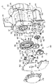
図1には第1の実施の形態に係るウェビング巻取装置10の構成が分解斜視図により示されている。
<Configuration of First Embodiment>
FIG. 1 is an exploded perspective view showing a configuration of a webbing take-up
この図に示されるように、ウェビング巻取装置10は、例えば、車両の骨格部材や補強部材等の車体構成部材に固定されるフレーム12を備えている。フレーム12は車体への取付状態で略車両前後方向に沿って互いに対向する脚板14、16を備えている。
As shown in this figure, the webbing take-up
これらの脚板14、16の間にはスプール18が設けられている。スプール18は軸方向が脚板14と脚板16との対向方向に沿った略円筒形状に形成されている。このスプール18には長尺帯状に形成されたウェビング20の長手方向基端部が係止されている。スプール18は、その中心軸線周りの一方である巻取方向に回転することで、ウェビング20をその長手方向基端側から巻取って格納し、例えば、乗員が身体にウェビング20を装着するにあたってウェビング20を引っ張ると、スプール18に巻取られているウェビング20が引出されつつ、巻取方向とは反対の引出方向にスプール18が回転する。
A
スプール18の内側には図示しないトーションシャフトが設けられている。トーションシャフトは軸方向がスプール18の軸方向に沿った棒状の部材とされている。トーションシャフトは、脚板14側の端部よりも脚板16側でスプール18に対して同軸的な相対回転が不能な状態でスプール18に連結されている。
A torsion shaft (not shown) is provided inside the
また、脚板14の脚板16とは反対側にはロック手段としてのロック機構22のハウジング24が脚板14に取り付けられており、上記のトーションシャフトの脚板14側の端部は、スプール18の中心軸線周りに回転自在にハウジング24に直接又は間接的に支持されている。ハウジング24の内側には、車両が急減速状態になった場合に作動し、作動することでトーションシャフトの脚板14側の端部が引出方向へ回転することを規制する所謂「VSIR機構」を構成する各種部品や、引出方向へのトーションシャフトの回転加速度が所定の大きさを超えた場合に作動し、作動することでトーションシャフトの脚板14側の端部が引出方向へ回転することを規制する所謂「WSIR機構」を構成する各種部品が収容されている。
Further, a
さらに、脚板14の脚板16とは反対側には強制引張手段としてのプリテンショナ26が設けられている。プリテンショナ26は車両急減速状態で作動し、作動することで、上記のトーションシャフトの脚板14側の端部又はスプール18に対して巻取方向への回転力を付与して、スプール18を強制的に巻取方向へ回転させる。
Further, a
一方、脚板14と脚板16との間のスプール18の下側にはモータ40が設けられている。モータ40は図示しない制御手段としてのECUを介して車両に搭載されたバッテリーと、車両の前方で走行する他の車両や、車両前方の障害物までの距離を測定するレーダ装置等の前方監視装置に電気的に接続されている。前方監視装置から出力された電気信号に基づき、車両の前方で走行する他の車両や車両前方の障害物までの距離が一定値未満になったとECUが判定すると、ECUがモータ40を作動させる。モータ40は出力軸42の軸方向がスプール18の軸方向と同じ向きとされており、出力軸42の先端側は脚板16に形成された図示しない透孔を通過して脚板16の外側(脚板16の脚板14とは反対側)に突出している。
On the other hand, a
さらに、脚板16の脚板14とは反対側には駆動力伝達機構50が設けられている。駆動力伝達機構50は脚板16の脚板14とは反対側で脚板16に取り付けられたギヤボックス52を備えている。ギヤボックス52は脚板16とは反対側へ向けて開口した凹形状に形成されている。このギヤボックス52の底部には孔部54が形成されており、脚板16の孔部を通過したモータ40の出力軸42が孔部54を通過してギヤボックス52の内側に入り込んでいる。
Further, a driving
ギヤボックス52に入り込んだ出力軸42の先端側には、外歯で平歯のギヤ56が出力軸42に対して同軸的且つ一体的に取り付けられている。このギヤ56の側方では、ギヤボックス52の底部に支持軸58が形成されている。支持軸58は軸方向が出力軸42の軸方向と同じ向きとされている。この支持軸58には二段ギヤ60が支持軸58周りに回転自在に支持されている。
An external
二段ギヤ60は外歯で平歯の大径ギヤ62を備えている。大径ギヤ62はギヤ56よりも大径で且つギヤ56よりも歯数が多く設定されておりギヤ56に噛み合っている。大径ギヤ62の軸方向側方には、大径ギヤ62よりも小径とされた外歯で平歯の小径ギヤ64が大径ギヤ62に対して同軸的且つ一体的に形成されている。この二段ギヤ60の回転半径方向側方では、ギヤボックス52の底部に支持軸68が形成されている。
The two-
支持軸68は軸方向が出力軸42や支持軸58の軸方向と同じ向きとされている。この支持軸68には二段ギヤ70が支持軸68周りに回転自在に支持されている。二段ギヤ70は外歯で平歯の大径ギヤ72を備えている。大径ギヤ72は小径ギヤ64よりも大径で且つ小径ギヤ64よりも歯数が多く設定されており小径ギヤ64に噛み合っている。大径ギヤ72の軸方向側方には、大径ギヤ72よりも小径とされた外歯で平歯の小径ギヤ74が大径ギヤ72に対して同軸的且つ一体的に形成されている。
The
この二段ギヤ70の回転半径方向側方では、ギヤボックス52の底部に支持軸78が形成されている。支持軸78は軸方向が出力軸42や支持軸58、68の軸方向と同じ向きとされている。この支持軸78には外歯で平歯のギヤ80が支持軸78周りに回転自在に支持されている。ギヤ80は小径ギヤ74よりも大径で且つ小径ギヤ74よりも歯数が多く設定されており小径ギヤ74に噛み合っている。
A
ギヤ80の回転半径方向側方にはクラッチ90が設けられている。クラッチ90は入力ギヤ92を備えている。入力ギヤ92は底壁部94を備えている。底壁部94には円孔96が形成されている。円孔96に対応してギヤボックス52に底部にはリング状の支持部98が形成されている。円孔96は入力ギヤ92の底部から脚板14とは反対側へ向けて立設されている。また、支持部98は、その中心軸線が上記のスプール18の中心軸線に対して略同軸となるように形成されている。
A clutch 90 is provided on the side of the
この支持部98は円孔96を貫通しており、底壁部94、すなわち、入力ギヤ92を支持部98の中心軸線周りに回転自在に支持している。底壁部94の外周部には、外歯で平歯のギヤ部100が形成されている。ギヤ部100は、底壁部94の円孔96に対して同軸的に形成されていると共に、上記のギヤ80よりも大径で、しかも、ギヤ80よりも歯数が多く、ギヤ80に噛み合っている。上記のように、ギヤ80は、二段ギヤ70、60を介してモータ40の出力軸42に設けられたギヤ56に機械的に連結されているため、モータ40が作動し、その駆動力で出力軸42が回転すると、出力軸42の回転が減速されてギヤ部100に伝わり、ギヤ部100、すなわち、入力ギヤ92が回転する。
The
一方、ギヤ部100の内側には一対の支持軸102が設けられている。各支持軸102は軸方向が円孔96の軸方向と同じ向きとされ、入力ギヤ92の底壁部94から脚板16とは反対側へ向けて突出形成されている。これらの支持軸102は、円孔96の中心を介して互いに対向するように形成されている。これらの支持軸102には連結パウル110が設けられている。各連結パウル110には円孔112が形成されている。円孔112には上記の支持軸102が通過しており、各連結パウル110は、対応する円孔112によって円孔112の中心軸線周りに回動可能に支持されている。
On the other hand, a pair of
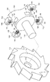
ギヤ部100の内側にはモータ側回転体としてのラチェットギヤ114が設けられている。図2に示されるように、このラチェットギヤ114には大径孔116が形成されている。大径孔116はラチェットギヤ114の中心に形成されて、スプール18側へ向けて開口した有底で内周形状が円形の孔とされている。また、ラチェットギヤ114には小径孔118が形成されている。小径孔118は大径孔116に対して同軸的に形成されており、一端が大径孔116の開口方向とは反対方向で開口していると共に、他端が大径孔116の底部にて開口している。
A
上記のラチェットギヤ114の大径孔116及び小径孔118には、底壁部94の円孔96を通過してギヤ部100の内側に入り込んでいるスプール側回転体としてのアダプタ182が入り込んで通過している。アダプタ182は上述したトーションシャフトに対して相対回転不能な状態でトーションシャフトの脚板16側の端部に装着されている。
The large-
図1から図3の各図に示されるように、アダプタ182の外周形状はスプール18に対して略同軸の円形とされたスライダ取付部184を備えている。このスライダ取付部184の一端には外径寸法がスライダ取付部184よりも小さな小径軸部186がスライダ取付部184に対して同軸的に形成されている。ラチェットギヤ114の中央に形成された小径孔118をアダプタ182の小径軸部186が貫通しており、この小径軸部186にラチェットギヤ114が回転自在に支持されている。
As shown in each of FIGS. 1 to 3, the outer peripheral shape of the
このアダプタ182のスライダ取付部184には開口形状が長方形状とされた複数のスライダ収容孔188が形成されている。スライダ収容孔188はスライダ取付部184の外周部にて開口した有底の孔とされ、底部から開口端への向きはアダプタ182の中心軸線から放射状に半径方向外方とされている。また、各スライダ収容孔188は開口端から底部までの長さ(すなわち、スライダ収容孔188の深さ)は同じに設定されており、さらに、各スライダ収容孔188はアダプタ182の中心周りに一定角度毎(本実施の形態では90度毎)に形成されている。
The
上記のようにアダプタ182の小径軸部186にラチェットギヤ114が支持された状態では、スライダ取付部184がラチェットギヤ114の大径孔116の内側に入り込み、大径孔116の内周面と各スライダ収容孔188の開口端とがアダプタ182及びラチェットギヤ114の回転半径方向に対向している。
In the state where the
このスライダ収容孔188の内側には圧接部材として回転伝達部材を構成するスライダ192が収容されている。スライダ192は圧接部194を備えている。圧接部194における大径孔116の内周面と対向する面は、大径孔116の内周面と同じ曲率で湾曲した曲面とされている。この圧接部194におけるスライダ取付部184の周方向両側の端部からは脚片196がスライダ取付部184の半径方向中央側へ延出されている。一方の脚片196に対して他方の脚片196は平行に形成されており、スライダ収容孔188の内側にはスライダ192の両脚片196が収容される。スライダ収容孔188に収容された脚片196はスライダ収容孔188の内周部に摺接し、これによって、スライダ192の移動方向がスライダ収容孔188の開口方向及びその反対方向に制限されている。
Inside the slider
また、スライダ192の一対の脚片196の間には付勢部材としての圧縮コイルばね198が設けられている。この圧縮コイルばね198は、一端がスライダ収容孔188の底部に圧接して、他端がスライダ192の圧接部194に圧接している。この圧縮コイルばね198の付勢力によってスライダ192はスライダ収容孔188の開口側へ付勢され、圧接部194が大径孔116の内周部に圧接している。また、各圧縮コイルばね198は付勢力が等しく設定されている。このため、各スライダ192の圧接部194は同じ大きさの力で大径孔116の内周部を押圧する。これにより、アダプタ182に対するラチェットギヤ114の相対的な位置関係、特に、アダプタ182の回転半径方向に沿った位置関係を安定させることができる。
Further, a
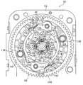
一方、図1から図3の各図に示されるように、上記のラチェットギヤ114の外周部には外歯のラチェット歯が形成されている。図3に示されるように、このラチェットギヤ114のラチェット歯に対応して、上記の連結パウル110には噛合部122が形成されている。
On the other hand, as shown in FIGS. 1 to 3, external ratchet teeth are formed on the outer periphery of the
連結パウル110は円孔112を貫通する支持軸102周りの一方へ回動することで、図3に示されるように、噛合部122がラチェットギヤ114の外周部へ接近して、ラチェットギヤ114のラチェット歯に噛合部122が噛み合う。ラチェットギヤ114のラチェット歯に噛合部122が噛み合った状態で入力ギヤ92が支持部98周りに巻取方向に回転すると、入力ギヤ92と共に巻取方向に回転する連結パウル110の噛合部122がラチェットギヤ114を巻取方向に押圧して、ラチェットギヤ114を入力ギヤ92と共に巻取方向に回転させる。
As the connecting
ここで、一方の支持軸102に対して他方の支持軸102は、入力ギヤ92の回転中心周りに180度ずれた状態で形成されている。これに対して、ラチェットギヤ114に形成された外歯のラチェット歯は奇数とされている。このため、一方の支持軸102に支持された連結パウル110の噛合部122がラチェットギヤ114のラチェット歯に噛み合うと、他方の支持軸102に支持された連結パウル110の噛合部122は、ラチェットギヤ114の回転周方向に沿ったラチェット歯の斜面の中間部に接してラチェット歯に噛み合わない。このような構成では、ラチェット歯の形成間隔の半分の角度だけラチェットギヤ114が回転すれば、何れかの連結パウル110の噛合部122がラチェットギヤ114のラチェット歯に噛み合う。
Here, the
なお、本実施の形態では、上記のようにラチェットギヤ114のラチェット歯の数を奇数に設定すると共に、両方の支持軸102を入力ギヤ92の回転中心周りに180度ずれた状態で形成することによって何れかの連結パウル110の噛合部122がラチェットギヤ114のラチェット歯に噛み合う構成とした。ラチェットギヤ114のラチェット歯の数や連結パウル110を支持する支持軸102の形成位置がこのような態様に限定されるものではない。
In the present embodiment, the number of ratchet teeth of the
したがって、両方の連結パウル110の噛合部122がラチェットギヤ114の各ラチェット歯に略同時に噛み合うようにラチェットギヤ114のラチェット歯の数や連結パウル110を支持する支持軸102の形成位置等を設定してもよい。また、本実施の形態は2つの連結パウル110を有する構成であったが、連結パウル110を3つ以上備える構成であってもよいし、連結パウル110を1つしか設けない構成であってもよい。
Accordingly, the number of ratchet teeth of the
一方、上記の支持軸102に対する入力ギヤ92の回転周方向に沿った引出方向側では、底壁部94に支持ピン124が形成されている。これらの支持ピン124の各々にはリターンスプリング126が取り付けられている。リターンスプリング126は中間部がコイル状とされた捩じりコイルばねで、その一端は底壁部94に形成された図示しない係止部に係止されている。これに対して、リターンスプリング126の他端側は連結パウル110のスプリング当接部128に圧接しており、支持軸102周りの他方、すなわち、噛合部122をラチェットギヤ114の外周部から離間させる向きに連結パウル110を付勢している。
On the other hand, a
また、クラッチ90は一対の干渉片140を備えている。図6に示されるように、干渉片140は基部142を備えている。基部142は幅方向が干渉片140の高さ方向、更に言えばスプール18の軸方向に沿った細幅の板状に形成されている。この基部142に対応して上記のギヤボックス52の底部には外側保持リング146と内側保持リング148とが形成されている。
The clutch 90 includes a pair of
これらの外側保持リング146及び内側保持リング148は上記の支持部98に対して同軸のリング状に形成されており、脚板16とは反対側へ向けてギヤボックス52の底部から立設されている。上記の干渉片140の基部142は、この外側保持リング146と内側保持リング148との間に入り込んでいると共に、そのばね性によって外側保持リング146の内周部や内側保持リング148の外周部に圧接している。
The
また、基部142の幅方向一端部(すなわち、基部142が外側保持リング146と内側保持リング148との間に入り込んだ状態で支持部98の底部とは反対側の基部142の幅方向端部)における基部142の長手方向中央側からは干渉部152が延出されている。図1及び図2に示されるように、干渉部152に対応して入力ギヤ92の底壁部94には透孔154が形成されている。透孔154は支持軸102に支持された連結パウル110の噛合部122の近傍に形成されている。外側保持リング146と内側保持リング148との間に基部142が配置された干渉片140は、干渉部152が透孔154を通過しており、特に干渉片140の初期状態では入力ギヤ92の回転周方向に沿った噛合部122の巻取方向側で干渉部152が噛合部122と対向している。
One end portion in the width direction of the base portion 142 (that is, the end portion in the width direction of the
一方、図1に示されるように、ギヤボックス52の脚板16とは反対側の開口端側には閉止板162が設けられている。閉止板162は図示しないボルトやねじ等の締結手段によってギヤボックス52に一体的に取り付けられている。ギヤボックス52に取り付けられた閉止板162は、ギヤボックス52の脚板16とは反対側の開口を閉止して、二段ギヤ60、70、80や入力ギヤ92(クラッチ90)の脱落を規制している。また、ギヤボックス52に取り付けられた閉止板162は、ギヤボックス52の開口を閉止するのみならず、入力ギヤ92における連結パウル110やリターンスプリング126を収容している側を閉止しており、入力ギヤ92内からの連結パウル110やリターンスプリング126の脱落を規制している。
On the other hand, as shown in FIG. 1, a
さらに、閉止板162には閉止板162の厚さ方向に貫通した透孔164が形成されており、上述した小径軸部186が透孔164を通過して閉止板162の外側に突出している。閉止板162の外側(閉止板162のギヤボックス52とは反対側)にはスプリングハウジング172が設けられている。
Further, a through
スプリングハウジング172はギヤボックス52に一体的に連結されている。透孔164を通過した小径軸部186はスプリングハウジング172の内側に入り込んで、スプリングハウジング172内に形成された図示しない軸受け部に回転自在に支持されている。また、スプリングハウジング172には図示しない渦巻きばねが収容されている。この渦巻きばねの渦巻き方向外側の端部はスプリングハウジング172に直接又は間接的に係止され、渦巻き方向内側の端部がスプリングハウジング172に入り込んだ小径軸部186に直接又は間接的に係止されている。
The
この渦巻きばねは、小径軸部186が引出方向に回転すると巻締められ、小径軸部186を巻取方向に付勢する。通常の状態でスプール18から引出されたウェビング20をスプール18に巻取らせて格納する際には、この渦巻きばねの付勢力でスプール18を巻取方向に回転させる。
This spiral spring is tightened when the small-
<第1の実施の形態の作用、効果>
次に、本ウェビング巻取装置10の動作の説明を通して本実施の形態の作用並びに効果について説明する。
<Operation and Effect of First Embodiment>
Next, the operation and effect of the present embodiment will be described through the operation of the webbing take-up
本ウェビング巻取装置10では、前方監視装置から出力された電気信号に基づき、車両の前方で走行する他の車両や、車両前方の障害物までの距離が一定値未満になったとECUが判定すると、ECUがモータ40を通電してモータ40を作動させる。モータ40が作動することで出力軸42が回転すると、出力軸42に設けられたギヤ56が出力軸42の回転を二段ギヤ60の大径ギヤ62に伝えて二段ギヤ60を回転させる。さらに、二段ギヤ60の小径ギヤ64は二段ギヤ70の大径ギヤ72に噛み合っているので、二段ギヤ60の回転は二段ギヤ70に伝えられて二段ギヤ70が回転する。この二段ギヤ70の回転は、小径ギヤ74に噛み合うギヤ80に伝えられ、更に、ギヤ80に噛み合うギヤ部100に減速して伝えられ、これにより、入力ギヤ92が巻取方向に回転する。
In this
入力ギヤ92が巻取方向に回転することで、入力ギヤ92の底壁部94に形成された支持軸102が巻取方向に回転し、これにより、支持軸102に支持されている連結パウル110が入力ギヤ92と共に巻取方向に回転する。ここで、上記のように、連結パウル110を構成する噛合部122の巻取方向側には、初期状態での干渉片140の干渉部152が位置しているので、入力ギヤ92と共に連結パウル110が巻取方向に回転すると噛合部122が干渉部152に当接して干渉部152を巻取方向に押圧する。
As the
干渉片140は自らの弾性に抗して基部142が湾曲した状態で外側保持リング146と内側保持リング148の間に入り込んで外側保持リング146と内側保持リング148とに圧接している。このため、基部142と外側保持リング146との接触部分及び基部142と内側保持リング148との接触部分における最大静止摩擦力を上回る大きさの力で基部142が押圧されないと、基部142が外側保持リング146と内側保持リング148との間を、その周方向に移動することはない。
The
このため、この状態では連結パウル110の噛合部122が干渉片140の干渉部152からの押圧反力を受けることでリターンスプリング126の付勢力に抗して支持軸102周りに回動し、噛合部122はラチェットギヤ114の外周部に接近する。各連結パウル110が上記のように回動することで、図4に示されるように、一方の連結パウル110の噛合部122がラチェットギヤ114のラチェット歯に噛み合うと、噛合部122がラチェットギヤ114のラチェット歯を巻取方向に押圧する。
For this reason, in this state, the meshing
さらに、この状態では、連結パウル110はこれ以上の回動が規制されているため、連結パウル110の噛合部122が干渉片140の干渉部152を押圧し続けることで干渉片140の干渉部152に付与される巻取方向への押圧力が基部142と外側保持リング146との接触部分及び基部142と内側保持リング148との接触部分における最大静止摩擦力を上回ると、干渉片140は外側保持リング146と内側保持リング148とに案内されて巻取方向に回転する。
Further, in this state, since the
これにより、入力ギヤ92が巻取方向に更に回転し、巻取方向への入力ギヤ92の回転が連結パウル110を介してラチェットギヤ114に伝わり、ラチェットギヤ114を巻取方向に回転させる。ラチェットギヤ114の大径孔116の内周面にはスライダ192の圧接部194が圧接しており、この圧接部194と大径孔116の内周面との間の摩擦によりスライダ192がラチェットギヤ114と共に巻取方向に回転する。このように巻取方向に回転するスライダ192はスライダ収容孔188の内周部を巻取方向に押圧してスライダ取付部184、すなわち、アダプタ182を巻取方向に回転させる。
As a result, the
このようにアダプタ182が巻取方向に回転することでスプール18が巻取方向に回転し、スプール18が巻取方向に回転することで、ウェビング20がスプール18に巻取られ、車両の乗員の身体に装着されているウェビング20の僅かな弛み、所謂「スラック」が除去される。
Thus, when the
このようなモータ40の駆動状態でスプール18がウェビング20をそれ以上巻取ることができなくなると(すなわち、スプール18の巻取方向への回転が規制されると)、ラチェットギヤ114がアダプタ182に対して巻取方向に相対回転しようとする。
When the
このように相対回転が生じようとした際のラチェットギヤ114の回転力が大径孔116の内周面とスライダ192の圧接部194との間の最大静止摩擦力を上回ると、スライダ192の圧接部194に対して大径孔116の内周面が巻取方向に滑る。これにより、アダプタ182に対してラチェットギヤ114が巻取方向に相対回転する。これにより、ラチェットギヤ114からアダプタ182への巻取方向への回転力の伝達を遮断又は軽減でき、スプール18の巻取方向への回転が規制された状態で、それ以上、スプール18が巻取方向に回転することを防止又は抑制できる。
When the rotational force of the
また、モータ40が上記のように駆動した状態で、ウェビング20を装着した乗員が車両前方側へ慣性移動すると、ウェビング20が引っ張られて、スプール18が巻取方向とは反対の引出方向に回転する。このような場合に、スプール18によってアダプタ182が引出方向(すなわち所定方向とは反対方向)に回転すると、スライダ192の圧接部194に対して大径孔116の内周面が巻取方向に滑る。これにより、ラチェットギヤ114からモータ40側における駆動力伝達機構50の二段ギヤ60、70等の各ギヤ列の歯に大きな荷重が作用することを防止又は抑制できる。これにより、駆動力伝達機構50を構成する各ギヤの機械的強度を特別に高く設定しなくてもよく、小型化や軽量化が可能になる。
Further, when the occupant wearing the
ここで、上記のように、本実施の形態では、アダプタ182に対するラチェットギヤ114の相対的な巻取方向への回転力が大径孔116の内周面とスライダ192の圧接部194との間の最大静止摩擦力を上回ると、スライダ192の圧接部194に対して大径孔116の内周面が巻取方向に滑る構成である。このため、アダプタ182に対してラチェットギヤ114が巻取方向に回転しても、衝撃音が発生しない。
Here, as described above, in this embodiment, the rotational force of the
なお、本実施の形態では、圧縮コイルばね198の付勢力によってスライダ192の圧接部194をラチェットギヤ114における大径孔116の内周部に圧接させた構成であったが、スライダ192を設けずに圧縮コイルばね198を回転伝達部材としてラチェットギヤ114における大径孔116の内周部に圧接させる構成としてもよい。
In this embodiment, the
<第2の実施の形態の構成>
次に、第2の実施の形態について説明する。
<Configuration of Second Embodiment>
Next, a second embodiment will be described.
図6には第2の実施の形態に係るウェビング巻取装置210の要部の構成が前記第1の実施の形態を説明するうえで用いた図2に対応する拡大分解斜視図によって示されている。
FIG. 6 shows the configuration of the main part of the webbing take-up
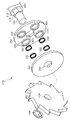
この図に示されるように、ウェビング巻取装置210はアダプタ182に代わるスプール側回転体としてのアダプタ212を備えている。アダプタ212はストッパ214を備えている。ストッパ214は外周形状がスプール18に対して同軸の円形に形成されている。このストッパ214のスプール18とは反対側の端部からは連続して回り止め部216が形成されている。回り止め部216は外周形状が多角形や星形、楕円形、スプライン形状等の非円形(本実施の形態では、六角形状)とされており、外周部におけるアダプタ212の中心から最も遠い部分であっても、ストッパ214の半径寸法よりも小さい。この回り止め部216のストッパ214とは反対側の端部に軸部186がストッパ214に対して同軸的に形成されている。
As shown in this figure, the webbing take-up
このアダプタ212には回転伝達部材を構成するホルダプレート222が設けられている。ホルダプレート222は、一例としてはアダプタ212に対して同軸の円板状に形成されており、その中央には回り止め部216と同形状の嵌合孔224が形成されている。
The
この嵌合孔224には上記の回り止め部216が通過しており、これにより、回り止め部216、ひいては、アダプタ212に対するホルダプレート222の相対回転が規制されている(すなわち、ホルダプレート222及びアダプタ212の一方が回転すれば他方が回転する)。また、回り止め部216が嵌合孔224を通過した状態で、ホルダプレート222はアダプタ212の軸方向にストッパ214と対向し、ホルダプレート222はストッパ214に当接することによってアダプタ212の軸方向に沿ったスプール18側への移動が規制される。
The
このホルダプレート222のストッパ214とは反対側の面には複数のスプリングホルダ226が形成されている。各々のスプリングホルダ226は軸方向がアダプタ212の軸方向と同じ向きの円筒形状とされており、ホルダプレート222の中心、ひいては、アダプタ212の中心に対する同心円周上でホルダプレート222の中心、ひいては、アダプタ212の中心周りに一定角度毎(本実施の形態では90度毎)に形成されている。これらのスプリングホルダ226の内側には付勢部材としての圧縮コイルばね232が配置されている。各々のスプリングホルダ226に設けられた圧縮コイルばね232は、同じ大きさの付勢力を有するように形成されている。
A plurality of
このホルダプレート222のストッパ214とは反対側には上記のホルダプレート22と共に回転伝達部材を構成する圧接プレート242が設けられている。この圧接プレート242の中央にはホルダプレート222に形成された嵌合孔224と同じ形状の嵌合孔244が形成されており、回り止め部216が通過している。このため、ホルダプレート222と同様に回り止め部216、ひいては、アダプタ212に対するホルダプレート222の相対回転が規制されている。ホルダプレート222のスプリングホルダ226に設けられた圧縮コイルばね232は圧接プレート242のホルダプレート222側の面に圧接しており、圧接プレート242をアダプタ212の軸方向にホルダプレート222から離間させるように付勢している。
On the opposite side of the
この圧接プレート242のホルダプレート222とは反対側にはラチェットギヤ114に代わるモータ側回転体としてのラチェットギヤ252が設けられている。ラチェットギヤ252の中央には、大径孔116や小径孔118が形成されておらず、代わりに透孔254が形成されている。透孔254はラチェットギヤ252の軸方向両端にて開口しており、その内径寸法は小径軸部186の外径寸法よりも僅かに大きく、この透孔254を小径軸部186が通過していることによってラチェットギヤ252が小径軸部186、ひいては、アダプタ212に回転自在に支持される。
A
また、ラチェットギヤ252の圧接プレート242とは反対側では小径軸部186にプッシュナット256が装着されている。ラチェットギヤ252は、小径軸部186の回り止め部216側で回り止め部216の軸方向端面に当接していると共に、この状態でラチェットギヤ252における回り止め部216とは反対側の端面にプッシュナット256が当接している。これにより、小径軸部186の軸方向に沿ったラチェットギヤ252の移動が規制され、例えば、圧縮コイルばね232からの付勢力を受けた圧接プレート242にラチェットギヤ252が押圧されても、ラチェットギヤ252が小径軸部186の軸方向に移動することを防止又は抑制できる。
A
<第2の実施の形態の作用、効果>
本実施の形態では、圧縮コイルばね232により付勢された圧接プレート242がラチェットギヤ252における圧接プレート242側の面に圧接する。ラチェットギヤ252がモータ40の駆動力で巻取方向に回転すると、圧接プレート242とラチェットギヤ252との間の摩擦によってラチェットギヤ252の回転が圧接プレート242に伝わり、圧接プレート242を巻取方向に回転させる。圧接プレート242は嵌合孔244にアダプタ212の回り止め部216が通過していることによってアダプタ212に対する相対回転が規制されている。このため、圧接プレート242が巻取方向に回転すると、アダプタ212が巻取方向に回転し、これによってスプール18が巻取方向に回転する。
<Operation and Effect of Second Embodiment>
In the present embodiment, the
一方、モータ40の駆動状態でスプール18がウェビング20をそれ以上巻取ることができなくなると(すなわち、スプール18の巻取方向への回転が規制されると)、ラチェットギヤ252がアダプタ212に対して巻取方向に相対回転しようとする。
On the other hand, when the
このように相対回転が生じようとした際のラチェットギヤ252の回転力がラチェットギヤ252と圧接プレート242との間の最大静止摩擦力を上回ると、ラチェットギヤ252が圧接プレート242に対して巻取方向に滑る。これにより、アダプタ212に対してラチェットギヤ252が巻取方向に相対回転する。これにより、ラチェットギヤ252からアダプタ212への巻取方向への回転力の伝達を遮断又は軽減でき、スプール18の巻取方向への回転が規制された状態で、それ以上、スプール18が巻取方向に回転することを防止又は抑制できる。
When the rotational force of the
このように、本実施の形態はラチェットギヤ252に圧接する圧接プレート242が付勢される方向はアダプタ212の軸方向である。しかしながら、ラチェットギヤ252と圧接プレート242との間の摩擦によってラチェットギヤ252の巻取方向の回転を圧接プレート242、ひいては、アダプタ212に伝え、また、ラチェットギヤ252の回転力がラチェットギヤ252と圧接プレート242との間の最大静止摩擦力を上回ることで、アダプタ212に対してラチェットギヤ252が巻取方向に相対回転する点に関しては前記第1の実施の形態と同じである。したがって、本実施の形態であっても、基本的に前記第1の実施の形態と同様の効果を得ることができる。
Thus, in this embodiment, the direction in which the
また、本実施の形態では、圧縮コイルばね232による圧接プレート242の付勢方向がアダプタ212の軸方向である。このため、圧接プレート242の中心軸線の向きがアダプタ212やラチェットギヤ252の中心軸線に対して傾き難い。
In the present embodiment, the biasing direction of the
さらに、上記のように同じ大きさの付勢力の圧縮コイルばね232をホルダプレート222の中心、ひいては、アダプタ212の中心に対して同心の円周上で一定角度毎に設けられている。このため、圧接プレート242をラチェットギヤ252に均一に圧接させることができる。
Further, as described above, the
なお、上記の各実施の形態は、何れもスプール側回転体としてのアダプタ182、212に回転伝達部材を設けた構成であってが、モータ側回転体としてのラチェットギヤ114、252に回転伝達部材を設けてもよいし、スプール側回転体としてのアダプタ182、212及びモータ側回転体としてのラチェットギヤ114、252の双方に回転伝達部材を設けてもよい。
In each of the above embodiments, the
10 ウェビング巻取装置
18 スプール
20 ウェビング
40 モータ
114 ラチェットギヤ(モータ側回転体)
182 アダプタ(スプール側回転体)
192 スライダ(回転伝達部材)
210 ウェビング巻取装置
212 アダプタ(スプール側回転体)
222 ホルダプレート(回転伝達部材)
242 圧接プレート(回転伝達部材)
252 ラチェットギヤ(モータ側回転体)
10 Webbing take-up
182 Adapter (Spool side rotating body)
192 Slider (Rotation transmission member)
210 Webbing take-up
222 Holder plate (rotation transmission member)
242 Pressure plate (Rotation transmission member)
252 Ratchet gear (motor side rotating body)
Claims (4)
前記スプールに対して一体的に設けられ或いは前記スプールに直接又は間接的に連結されて、所定方向への回転を前記スプールに伝えて前記スプールを前記巻取方向に回転させるスプール側回転体と、
モータと、
前記モータの駆動力が伝えられて前記所定方向へ回転するモータ側回転体と、
前記モータ側回転体及び前記スプール側回転体のうちの一方の回転体に設けられて前記一方の回転体と共に回転し、且つ、前記一方の回転体の回転半径方向中央側への向き又は前記回転半径方向外方に沿った付勢力で前記モータ側回転体及び前記スプール側回転体のうちの他方の回転体に圧接して、前記他方の回転体との間の摩擦で前記モータ側回転体の回転を前記スプール側回転体に伝えると共に、前記スプール側回転体に対する前記モータ側回転体の前記所定方向への回転力が、前記他方の回転体との間で生ずる最大静止摩擦力を越えた場合に前記一方の回転体と共に前記他方の回転体に対して相対回転する回転伝達部材と、
を備えるウェビング巻取装置。 A spool that winds up the webbing by locking the longitudinal base end side of the webbing and rotating in one winding direction around the axis;
A spool-side rotating body that is provided integrally with the spool or is directly or indirectly connected to the spool and transmits rotation in a predetermined direction to the spool to rotate the spool in the winding direction;
A motor,
A motor-side rotating body that rotates in the predetermined direction when the driving force of the motor is transmitted;
Provided on one of the motor-side rotating body and the spool-side rotating body and rotates together with the one rotating body, and the direction of the one rotating body toward the center in the rotational radius direction or the rotation The motor-side rotating body is pressed against the other rotating body of the motor-side rotating body and the spool-side rotating body by an urging force along a radially outward direction, and friction between the motor-side rotating body and the other rotating body. When the rotation is transmitted to the spool-side rotator, and the rotational force in the predetermined direction of the motor-side rotator with respect to the spool-side rotator exceeds the maximum static friction force generated with the other rotator A rotation transmitting member that rotates relative to the other rotating body together with the one rotating body;
A webbing take-up device comprising:
前記スプールに対して一体的に設けられ或いは前記スプールに直接又は間接的に連結されて、所定方向への回転を前記スプールに伝えて前記スプールを前記巻取方向に回転させるスプール側回転体と、
モータと、
前記モータの駆動力が伝えられて前記所定方向へ回転するモータ側回転体と、
前記モータ側回転体及び前記スプール側回転体のうちの一方の回転体に設けられて前記一方の回転体と共に回転し、且つ、前記一方の回転体の軸方向に沿った付勢力で前記モータ側回転体及び前記スプール側回転体のうちの他方の回転体に圧接して、前記他方の回転体との間の摩擦で前記モータ側回転体の回転を前記スプール側回転体に伝えると共に、前記スプール側回転体に対する前記モータ側回転体の前記所定方向への回転力が、前記他方の回転体との間で生ずる最大静止摩擦力を越えた場合に前記一方の回転体と共に前記他方の回転体に対して相対回転する回転伝達部材と、
を備えるウェビング巻取装置。 A spool that winds up the webbing by locking the longitudinal base end side of the webbing and rotating in one winding direction around the axis;
A spool-side rotating body that is provided integrally with the spool or is directly or indirectly connected to the spool and transmits rotation in a predetermined direction to the spool to rotate the spool in the winding direction;
A motor,
A motor-side rotating body that rotates in the predetermined direction when the driving force of the motor is transmitted;
The motor-side rotating body and the spool-side rotating body are provided on one of the rotating bodies and rotate together with the one rotating body, and the motor side is biased along the axial direction of the one rotating body. The rotating body and the other rotating body of the spool side rotating body are pressed against each other, and the rotation of the motor side rotating body is transmitted to the spool side rotating body by friction between the rotating body and the spool. When the rotational force in the predetermined direction of the motor side rotating body with respect to the side rotating body exceeds the maximum static frictional force generated between the rotating body and the other rotating body, the one rotating body and the other rotating body A rotation transmitting member that rotates relative to the
A webbing take-up device comprising:
Priority Applications (1)
| Application Number | Priority Date | Filing Date | Title |
|---|---|---|---|
| JP2012192275A JP2014046855A (en) | 2012-08-31 | 2012-08-31 | Webbing take-up device |
Applications Claiming Priority (1)
| Application Number | Priority Date | Filing Date | Title |
|---|---|---|---|
| JP2012192275A JP2014046855A (en) | 2012-08-31 | 2012-08-31 | Webbing take-up device |
Publications (1)
| Publication Number | Publication Date |
|---|---|
| JP2014046855A true JP2014046855A (en) | 2014-03-17 |
Family
ID=50606940
Family Applications (1)
| Application Number | Title | Priority Date | Filing Date |
|---|---|---|---|
| JP2012192275A Pending JP2014046855A (en) | 2012-08-31 | 2012-08-31 | Webbing take-up device |
Country Status (1)
| Country | Link |
|---|---|
| JP (1) | JP2014046855A (en) |
Cited By (2)
| Publication number | Priority date | Publication date | Assignee | Title |
|---|---|---|---|---|
| JP2015168351A (en) * | 2014-03-07 | 2015-09-28 | 株式会社東海理化電機製作所 | webbing take-up device |
| JP2016156522A (en) * | 2015-02-23 | 2016-09-01 | リンナイ株式会社 | Fire power adjustment device |
-
2012
- 2012-08-31 JP JP2012192275A patent/JP2014046855A/en active Pending
Cited By (2)
| Publication number | Priority date | Publication date | Assignee | Title |
|---|---|---|---|---|
| JP2015168351A (en) * | 2014-03-07 | 2015-09-28 | 株式会社東海理化電機製作所 | webbing take-up device |
| JP2016156522A (en) * | 2015-02-23 | 2016-09-01 | リンナイ株式会社 | Fire power adjustment device |
Similar Documents
| Publication | Publication Date | Title |
|---|---|---|
| JP5364463B2 (en) | Webbing take-up device | |
| JP5015863B2 (en) | Webbing take-up device | |
| JP4699725B2 (en) | Motor retractor | |
| US8376258B2 (en) | Webbing take-up device | |
| KR20130143496A (en) | Webbing winding device | |
| JP5872390B2 (en) | Webbing take-up device | |
| JP5430440B2 (en) | Webbing take-up device | |
| JP5452186B2 (en) | Engaging member support structure and webbing take-up device | |
| JP5112964B2 (en) | Webbing take-up device | |
| JP5331048B2 (en) | Webbing take-up device | |
| JP5112963B2 (en) | Webbing take-up device | |
| JP5823355B2 (en) | Webbing take-up device | |
| JP2014046855A (en) | Webbing take-up device | |
| JP2014046854A (en) | Webbing taking-up device | |
| CN107585128A (en) | Webbing take-up device | |
| JP5314572B2 (en) | Webbing take-up device | |
| JP2010253969A (en) | Webbing take-up device | |
| JP5955151B2 (en) | Webbing take-up device | |
| JP5911794B2 (en) | Webbing take-up device. | |
| JP2014046856A (en) | Webbing take-up device | |
| JP6081395B2 (en) | Webbing take-up device | |
| JP2014084072A (en) | Webbing take-up device | |
| JP2019218012A (en) | Seat belt retractor | |
| JP6081396B2 (en) | Webbing take-up device | |
| JP2009280024A (en) | Webbing retractor device |