JP2014041602A - Information reading apparatus - Google Patents
Information reading apparatus Download PDFInfo
- Publication number
- JP2014041602A JP2014041602A JP2013134588A JP2013134588A JP2014041602A JP 2014041602 A JP2014041602 A JP 2014041602A JP 2013134588 A JP2013134588 A JP 2013134588A JP 2013134588 A JP2013134588 A JP 2013134588A JP 2014041602 A JP2014041602 A JP 2014041602A
- Authority
- JP
- Japan
- Prior art keywords
- information
- case
- electronic pen
- unit
- light source
- Prior art date
- Legal status (The legal status is an assumption and is not a legal conclusion. Google has not performed a legal analysis and makes no representation as to the accuracy of the status listed.)
- Pending
Links
- 230000001678 irradiating effect Effects 0.000 claims abstract description 6
- 101000579646 Penaeus vannamei Penaeidin-1 Proteins 0.000 description 49
- 238000005516 engineering process Methods 0.000 description 20
- 239000004973 liquid crystal related substance Substances 0.000 description 14
- 238000000034 method Methods 0.000 description 12
- 239000002184 metal Substances 0.000 description 11
- 229910052751 metal Inorganic materials 0.000 description 11
- 239000000758 substrate Substances 0.000 description 10
- 238000010586 diagram Methods 0.000 description 9
- 230000001133 acceleration Effects 0.000 description 6
- 239000000463 material Substances 0.000 description 5
- 230000003287 optical effect Effects 0.000 description 4
- 239000003086 colorant Substances 0.000 description 3
- 239000010408 film Substances 0.000 description 3
- 239000011159 matrix material Substances 0.000 description 3
- 239000010409 thin film Substances 0.000 description 3
- 239000000853 adhesive Substances 0.000 description 2
- 230000001070 adhesive effect Effects 0.000 description 2
- 239000012790 adhesive layer Substances 0.000 description 2
- 238000000149 argon plasma sintering Methods 0.000 description 2
- 230000005540 biological transmission Effects 0.000 description 2
- 230000001276 controlling effect Effects 0.000 description 2
- 210000003811 finger Anatomy 0.000 description 2
- 239000010410 layer Substances 0.000 description 2
- 239000011347 resin Substances 0.000 description 2
- 229920005989 resin Polymers 0.000 description 2
- VYZAMTAEIAYCRO-UHFFFAOYSA-N Chromium Chemical compound [Cr] VYZAMTAEIAYCRO-UHFFFAOYSA-N 0.000 description 1
- RYGMFSIKBFXOCR-UHFFFAOYSA-N Copper Chemical compound [Cu] RYGMFSIKBFXOCR-UHFFFAOYSA-N 0.000 description 1
- 101000579647 Penaeus vannamei Penaeidin-2a Proteins 0.000 description 1
- 238000006243 chemical reaction Methods 0.000 description 1
- 238000004891 communication Methods 0.000 description 1
- 229910052802 copper Inorganic materials 0.000 description 1
- 239000010949 copper Substances 0.000 description 1
- 238000001514 detection method Methods 0.000 description 1
- 239000011521 glass Substances 0.000 description 1
- 239000000203 mixture Substances 0.000 description 1
- 230000010287 polarization Effects 0.000 description 1
- 230000001105 regulatory effect Effects 0.000 description 1
- 210000003813 thumb Anatomy 0.000 description 1
Images


Classifications
-
- G—PHYSICS
- G09—EDUCATION; CRYPTOGRAPHY; DISPLAY; ADVERTISING; SEALS
- G09G—ARRANGEMENTS OR CIRCUITS FOR CONTROL OF INDICATING DEVICES USING STATIC MEANS TO PRESENT VARIABLE INFORMATION
- G09G3/00—Control arrangements or circuits, of interest only in connection with visual indicators other than cathode-ray tubes
- G09G3/20—Control arrangements or circuits, of interest only in connection with visual indicators other than cathode-ray tubes for presentation of an assembly of a number of characters, e.g. a page, by composing the assembly by combination of individual elements arranged in a matrix no fixed position being assigned to or needed to be assigned to the individual characters or partial characters
- G09G3/34—Control arrangements or circuits, of interest only in connection with visual indicators other than cathode-ray tubes for presentation of an assembly of a number of characters, e.g. a page, by composing the assembly by combination of individual elements arranged in a matrix no fixed position being assigned to or needed to be assigned to the individual characters or partial characters by control of light from an independent source
- G09G3/3406—Control of illumination source
-
- G—PHYSICS
- G06—COMPUTING; CALCULATING OR COUNTING
- G06F—ELECTRIC DIGITAL DATA PROCESSING
- G06F3/00—Input arrangements for transferring data to be processed into a form capable of being handled by the computer; Output arrangements for transferring data from processing unit to output unit, e.g. interface arrangements
- G06F3/01—Input arrangements or combined input and output arrangements for interaction between user and computer
- G06F3/03—Arrangements for converting the position or the displacement of a member into a coded form
- G06F3/0304—Detection arrangements using opto-electronic means
- G06F3/0317—Detection arrangements using opto-electronic means in co-operation with a patterned surface, e.g. absolute position or relative movement detection for an optical mouse or pen positioned with respect to a coded surface
- G06F3/0321—Detection arrangements using opto-electronic means in co-operation with a patterned surface, e.g. absolute position or relative movement detection for an optical mouse or pen positioned with respect to a coded surface by optically sensing the absolute position with respect to a regularly patterned surface forming a passive digitiser, e.g. pen optically detecting position indicative tags printed on a paper sheet
-
- G—PHYSICS
- G06—COMPUTING; CALCULATING OR COUNTING
- G06F—ELECTRIC DIGITAL DATA PROCESSING
- G06F3/00—Input arrangements for transferring data to be processed into a form capable of being handled by the computer; Output arrangements for transferring data from processing unit to output unit, e.g. interface arrangements
- G06F3/01—Input arrangements or combined input and output arrangements for interaction between user and computer
- G06F3/03—Arrangements for converting the position or the displacement of a member into a coded form
- G06F3/033—Pointing devices displaced or positioned by the user, e.g. mice, trackballs, pens or joysticks; Accessories therefor
- G06F3/0354—Pointing devices displaced or positioned by the user, e.g. mice, trackballs, pens or joysticks; Accessories therefor with detection of 2D relative movements between the device, or an operating part thereof, and a plane or surface, e.g. 2D mice, trackballs, pens or pucks
- G06F3/03545—Pens or stylus
Abstract
Description
本技術は、表示装置の表示面に手書き入力が可能な情報表示装置などに使用する情報読取装置に関するものである。 The present technology relates to an information reading device used for an information display device capable of handwritten input on a display surface of a display device.
紙などの印刷媒体上に、符号化した座標情報を含む2次元コードを配置することによって、その印刷媒体上に形成された画像情報の位置を特定する技術が知られている(特許文献1参照)。 A technique is known in which a position of image information formed on a print medium is specified by placing a two-dimensional code including encoded coordinate information on a print medium such as paper (see Patent Document 1). ).
また、表示装置に手書き入力可能な技術として、抵抗圧方式または静電容量方式などの方式によって表示装置上の座標を入力ペンなどで検出し、その検出した座標情報に基づき文字などの情報を表示するものなどがある。この装置では、表示装置上の座標指示範囲と表示手段の表示画面とが対応づけられ、表示装置の表示面上で入力ペンを移動させると、それに応じて表示画面上に文字などの情報を表示するように構成されている。 In addition, as a technique that allows handwriting input to the display device, the coordinates on the display device are detected with an input pen or the like by a method such as a resistance pressure method or a capacitance method, and information such as characters is displayed based on the detected coordinate information There are things to do. In this device, the coordinate instruction range on the display device is associated with the display screen of the display means, and when the input pen is moved on the display surface of the display device, information such as characters is displayed on the display screen accordingly. Is configured to do.
本技術は、高精細な手書き入力が可能な情報表示装置などに使用する情報読取装置において、コンパクトで使い勝手の良い構造とすることを目的とするものである。 An object of the present technology is to provide a compact and easy-to-use structure in an information reading apparatus used for an information display apparatus capable of high-definition handwritten input.
本技術は、光学的に読み取り可能な複数個のマークを有する情報パターンに光を照射する光源部と、前記情報パターンから情報を読み取る画像読取ユニットと、前記光源部および画像読取ユニットを収容し、先端に、前記光源部からの光を情報パターンに照射するとともに前記画像読取ユニットが情報を読み取るための光が入射する開口部を有するケースとを備え、前記ケースは、先端部に、ケースの他の部分より径を大きくすることにより形成した突出部を備えたことを特徴とする。 The present technology includes a light source unit that emits light to an information pattern having a plurality of optically readable marks, an image reading unit that reads information from the information pattern, and the light source unit and the image reading unit. And a case having an opening for irradiating the information pattern with light from the light source unit and receiving light for reading information by the image reading unit. It is characterized by having a protruding portion formed by making the diameter larger than this portion.
本技術によれば、高精細な手書き入力が可能な情報表示装置などに使用する情報読取装置において、コンパクトで使い勝手の良い構造を実現することができる。 According to the present technology, a compact and easy-to-use structure can be realized in an information reading device used for an information display device capable of high-definition handwriting input.
以下、本技術の一実施の形態による情報読取装置が使用される情報表示装置の一例として、液晶表示装置を用いた場合を例示して説明するが、EL表示装置などの他の表示装置を用いてもよい。 Hereinafter, a case where a liquid crystal display device is used will be described as an example of an information display device in which an information reading device according to an embodiment of the present technology is used, but other display devices such as an EL display device are used. May be.
但し、必要以上に詳細な説明は省略する場合がある。例えば、既によく知られた事項の詳細説明や実質的に同一の構成に対する重複説明を省略する場合がある。これは、以下の説明が不必要に冗長になるのを避け、当業者の理解を容易にするためである。 However, more detailed description than necessary may be omitted. For example, detailed descriptions of already well-known matters and repeated descriptions for substantially the same configuration may be omitted. This is to avoid the following description from becoming unnecessarily redundant and to facilitate understanding by those skilled in the art.
なお、発明者らは、当業者が本技術を十分に理解するために添付図面および以下の説明を提供するのであって、これらによって特許請求の範囲に記載の主題を限定することを意図するものではない。 In addition, the inventors provide the accompanying drawings and the following description in order for those skilled in the art to fully understand the present technology, and these are intended to limit the subject matter described in the claims. is not.
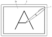
図1は、本技術の一実施の形態による情報読取装置を用いた情報表示装置の概略構成を示す図である。図1に示すように、情報表示装置は、手書き入力可能な情報読取装置としての光学式の電子ペン1と、この電子ペン1により指示された位置情報を受け取り、表示面2aに文字や図形などを表示する表示パネルを有する表示装置2とを備えている。また、図1には示していないが、表示装置2の表示パネルの表示領域には、電子ペン1により光学的に読み取り可能なドット状の複数個のマークを有する情報パターンが配置されている。
FIG. 1 is a diagram illustrating a schematic configuration of an information display device using an information reading device according to an embodiment of the present technology. As shown in FIG. 1, the information display device receives an optical
すなわち、本技術による情報表示装置は、表示装置2に、表示面2aにおける位置座標を示す情報パターンが配置され、電子ペン1により情報パターンを光学的なイメージパターンとして読み取ることにより、ユーザが表示面2aに手書き入力している位置情報を特定することができる。すなわち、電子ペン1は、表示装置2に配置された情報パターンに対して検出光を照射し、情報パターンのマークを光学的なイメージパターンとして読み取る動作を行う。これにより、電子ペン1が読み取った位置情報から電子ペン1の軌跡、すなわちユーザが手書き入力した文字などの筆跡を検出することができる。
That is, in the information display device according to the present technology, the information pattern indicating the position coordinates on the
また、情報表示装置は、電子ペン1が読み取った位置情報を表示装置2に送信する。表示装置2は、電子ペン1から送信される位置情報に基づいて、表示面2aに表示される表示情報を変更する動作を行う。したがって、ユーザは、紙の上にペンで文字などを手書き入力するように、表示装置2の表示面2a上に電子ペン1で文字や図形などを記入することができる。また、電子ペン1を消しゴムのように用いることもできる。この場合も文字や図形などを記入するときと同様に、電子ペン1で情報パターンを読み取ることで、電子ペン1の位置を特定し、そして、特定された位置情報に基づいて、表示面2aに表示された表示情報を削除する動作を行うことにより実現することができる。
Further, the information display device transmits the position information read by the
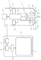
図2は、本技術の一実施の形態による情報表示装置において、電子ペン1と表示装置2の構成を示す模式図である。
FIG. 2 is a schematic diagram illustrating configurations of the
図2に示すように、電子ペン1は、表示装置2に赤外光を照射する赤外光照射部である光源部と、表示装置2から反射された赤外光を受光して、情報パターンのマークを光学的なイメージパターンの画像として読み取る画像読取ユニットとを備えている。光源部は、少なくとも赤外光を出射する光源である発光ダイオード(以下、LEDという)111により構成され、LED111から出射された赤外光を集光する集光レンズ112を備えている。画像読取ユニットは、少なくとも表示装置2から反射された画像を読み取る撮像素子(CCD)からなる画像読取部121により構成されている。また、表示装置2から反射され、電子ペン1に入射する赤外光を集光する集光レンズ122と、可視光領域の波長の光をカットして赤外光を透過させる赤外線フィルター(IRフィルター)123とを備えている。
As shown in FIG. 2, the
電子ペン1のLED111から放射された赤外光113は、集光レンズ112で集光され、表示装置2の表示面2aの特定位置に照射される。一方、表示装置2から反射された赤外光124は、集光レンズ122で集光され、赤外線フィルター(IRフィルター)123を通過して、画像読取部121に入射する。
すなわち、表示装置2の表示面2aのうち、所定範囲の読取領域の光が集光レンズ122によって画像読取部121の受光面上に集光され、電子ペン1は、画像読取部121が読取領域に含まれる情報パターンの位置情報を示すマークの画像を読み取る。画像読取部121によって読み取られた画像情報は、処理回路部13に送られる。処理回路部13は、情報パターンに含まれるドット状のマークのイメージを認識し、認識したマークのイメージパターンの画像データを処理して、電子ペン1が指示した位置の座標を検出する。また、処理回路部13は、読み取った画像情報をデータ信号に変換して送信部14に送る。送信部14は、無線通信により、表示装置2の受信部21に座標データを送信する。
That is, light in a predetermined range of the reading area on the
表示装置2は、受信部21が受信した受信データを処理回路部22で処理することによりパネル駆動回路部23を制御する。このパネル駆動回路部23により表示パネル24の表示動作を制御することにより、電子ペン1が認識した座標位置に基づき表示パネル24の表示面2aに文字や図形などを表示する。
The
以上の一連の動作は、電子ペン1の先端に配置されたペン先15が表示面2aに接しているときに行われる。すなわち、電子ペン1は、先端にペン先15を有し、内部にペン先15の筆圧を感知する圧力センサ16が配置されている。電子ペン1のペン先15が表示装置2の表示面2aに接すると、その情報が圧力センサ16から処理回路部13に送られ、この信号が送られてきたことに応答して、処理回路部13は、画像読取部121の読取出力を処理するように動作する。
The series of operations described above is performed when the
また、電子ペン1は、圧力センサ16の出力に応じて線の太さや濃さを変えることも可能である。具体的には、圧力センサ16の出力が大きくなるに伴って、線を太くしたり、濃くしたりすることができる。
In addition, the
なお、電子ペン1の先端が表示面2aに接しているときに読取動作を行う構成に限らず、例えば、ユーザが読取指令を入力するためのスイッチ17を設け、そのスイッチ17が押されたことに応答して、電子ペン1が表示面2aと離れている場合であっても読取動作が行われるように構成してもよい。
Note that the present invention is not limited to the configuration in which the reading operation is performed when the tip of the
また、電子ペン1には、電子ペン1の傾きによりペン先の座標位置が異なることから、電子ペン1の角度を検出するための角度センサ18が内蔵されている。例えば、電子ペン1が垂直の場合は、電子ペン1の真下にペン先の座標がある。電子ペン1が大きく傾くと、ペン先の座標は、電子ペン1の真下から大きく離れた位置になる。角度センサ18により電子ペン1の傾きを計測し、電子ペン1の傾きデータを処理回路部13に伝送する。処理回路部13は、傾きデータに基づき、画像読取部121で取得した情報パターンの情報を補正することにより、電子ペン1の傾きに影響されずに、正しい位置情報を求めることが可能となる。
The
また、電子ペン1には、電子ペン1の移動速度(加速度を含む)を検出するための加速度センサ19が内蔵されている。加速度センサ19は、電子ペン1の移動方向、および加速度のデータを検出して処理回路部13に伝送する。処理回路部13が、加速度センサ19から伝送される電子ペン1の移動方向データ、加速度データに基づいて演算を行うことにより、電子ペン1の移動量、移動方向などを求めることが可能となる。
Further, the
図3、図4は、表示装置2の表示面2aに配置された情報パターンの一例と、情報パターンから位置座標を求める方法の一例を示す説明図である。
3 and 4 are explanatory diagrams showing an example of an information pattern arranged on the
図3に示すように、表示装置2の表示面2aの表示領域には、特定の配列パターンで複数個のマーク31が形成された情報パターン3が配置されている。そして、表示面2a内のmドット×nドット、例えば6ドット×6ドットの画素領域を単位領域Aとしたとき、その単位領域A内の情報パターン3に形成されたマークを電子ペン1が読み取ることにより、電子ペン1が指示している位置座標を認識することができる。
As shown in FIG. 3, an
図4(a)、(b)、(c)、(d)は、情報パターン3におけるマーク31の配列パターンと、位置座標変換の方法の一例を示す説明図である。この例においては、図4(a)〜(d)に示すように、情報パターン3のマーク31は、格子状の基準線Xと基準線Yとにより形成される交点を基準にして、基準線X、Yの交点に対し、右側、上側、左側、下側に配置された配列パターンになるように、マーク31a、31b、31c、31dを形成している。そして、それぞれのマーク31a、31b、31c、31dに対し、例えば符号「1」、「2」、「3」、「4」の位置座標を示す符号を割り当てておくことにより、図3に示すように、単位領域A内の情報パターン3に形成されたマーク31を電子ペン1が読み取ることにより、読み取った単位領域Aの位置座標を判定することが可能となる。
4A, 4 </ b> B, 4 </ b> C, and 4 </ b> D are explanatory diagrams illustrating an example of the arrangement pattern of the
すなわち、情報パターン3は、例えば6ドット×6ドットの単位領域Aの中に36個のマーク31が4種類の配列位置のいずれかで配置されており、この配列パターンを組み合わせることで、表示面2a内の特定位置に応じて、その特定位置の座標位置を表す情報パターンを形成することができる。
That is, in the
ここで、情報パターン3のマーク31は、可視光を透過し、赤外線を吸収、または反射する材料で形成することにより、表示装置2の表示面2aに表示される可視光領域の表示画像に対する影響を少なくすることができる。また、マーク31は、赤外光が照射されることにより、入射光の方向を変化させるように光散乱や回折格子の特性を有する材料で形成してもよい。この場合は、マーク31が光散乱性、回折性を有していることにより、マーク31に入射した光がマーク31で反射(散乱、拡散、回折、位相変化、屈曲)され、再び表示装置2の外部に出力されることとなり、この反射した光によりマーク31を検出することができる。
Here, the
次に、情報表示装置の表示装置2において、表示パネルの構成の一例を説明する。
Next, an example of the configuration of the display panel in the
図5は、表示装置2において、情報パターンを配置した表示パネルの構成を示す概略構成図である。この図5に示す表示パネルは、アクティブマトリクス方式のTFTカラー液晶表示パネルの例を示している。
FIG. 5 is a schematic configuration diagram showing a configuration of a display panel in which an information pattern is arranged in the
図5において、液晶表示パネル部は、対向する2枚のガラス基板などの透光性の基板41、42の間に液晶部材43を封入することにより構成されている。図示していないが、液晶表示パネル部の下方の基板41上には、液晶の駆動素子である薄膜トランジスタと、一方の透明電極と、信号電極と、走査電極とが形成されている。また、上方の基板42の基板41と対向する側の面には、少なくとも赤(R)、緑(G)、青(B)の各色で構成されたカラーフィルタ44と、各色が透過可能な開口部を有するとともに、各色の境界部を遮光するクロムなどの金属薄膜からなる遮光部材であるブラックマトリクス45と、他方の透明電極とが形成されている。そして、2枚の基板41、42に形成した透明電極間には、液晶部材43が配置される。さらに、それぞれの基板41、42の外側の面には、偏光板46が貼り付けにより配置されている。
In FIG. 5, the liquid crystal display panel unit is configured by enclosing a
なお、カラーフィルタ44は、RGBに限定されるものではなく、シアン(C)、マゼンダ(M)、イエロー(Y)の色の画素を形成してもよい。また、白(W)の色の画素を形成してもよい。
Note that the
この液晶表示パネル部の背面側、すなわち下方の基板41の偏光板46側には、バックライト装置を構成する面光源部材47と拡散反射シート48が配置されている。また、液晶表示パネル部の表示面側、すなわち上方の基板42の偏光板46側には、オンセル型で静電容量方式のタッチパネル49が配置されている。なお、タッチパネル49については、インセル型や抵抗感圧方式などのタッチパネルでもよく、さらにはタッチパネル49自体を省いた構成としてもよい。
A surface
液晶表示パネル部は、複数の発光色のサブピクセルからなる画素がマトリクス状に複数個配置された構成であり、それぞれの画素を構成するサブピクセルの薄膜トランジスタそれぞれのオンオフを制御し、液晶部材43の偏光性を選択的に制御することで、文字や画像をカラー表示することができる。 The liquid crystal display panel unit has a configuration in which a plurality of pixels composed of a plurality of sub-pixels of light emission colors are arranged in a matrix, and controls on / off of each thin film transistor of the sub-pixel constituting each pixel. Characters and images can be displayed in color by selectively controlling the polarization.
また、液晶表示パネル部のタッチパネル49上には、電子ペン1により位置情報の読み取りを行うための複数個のマーク31を有する情報パターン3が配置されている。この情報パターン3は、図5に示すように、樹脂製の透光性のベースフィルム32上に、円形状や方形状などの複数個のマーク31を所定の配列パターンで形成し、そのマーク31を覆うようにベースフィルム32上に屈折率を調整するための透光性の樹脂層33を形成することにより構成されている。さらに、樹脂層33上には、透光性の粘着材からなる粘着層34が設けられており、情報パターン3は、ベースフィルム32が表示面側にくるように、粘着層34により液晶表示パネル部のタッチパネル49上に貼り付けにより配置されている。
An
情報パターン3のマーク31は、可視光を透過し、赤外線を吸収する材料により形成されており、液晶表示パネル部で表示される可視光領域のカラー表示画像に対する影響を少なくすることができる。
The
図5に示すように、電子ペン1から放射された赤外光113は、まず情報パターン3に照射される。このとき、情報パターン3において、マーク31が配置された位置では赤外光113が吸収され、マーク31が配置されていない位置では、赤外光113は液晶表示パネル部を透過し、拡散反射シート48で反射されて、電子ペン1に入射する。すなわち、電子ペン1は、入射してくる赤外光124を画像読取部121で読み取ることにより、情報パターン3に形成されたマーク31による座標情報を検出することができる。
As shown in FIG. 5, the
次に、本技術の一実施の形態における情報読取装置としての電子ペンについて、図6〜図11を用いて説明する。 Next, an electronic pen as an information reading device according to an embodiment of the present technology will be described with reference to FIGS.
図6は、本技術の一実施の形態による電子ペンの外観を示す斜視図である。図7は、本技術の一実施の形態による電子ペンの外観を横方向から見た平面図である。 FIG. 6 is a perspective view showing an appearance of the electronic pen according to the embodiment of the present technology. FIG. 7 is a plan view of the appearance of the electronic pen according to the embodiment of the present technology as viewed from the lateral direction.
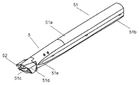
図6、図7に示すように、電子ペン5は、上ケース51aと下ケース51bとからなる樹脂製の筒状のケース51内に、情報パターン3に赤外光を照射する光源部および情報パターン3から情報を読み取る画像読取ユニットを収容することにより構成されている。このケース51内には、光源部や画像読取ユニット以外に、バッテリなども収容されている。また、ケース51の先端には、赤外光を照射するとともに、表示装置から反射してくる赤外光が入射する開口部51cが設けられ、その開口部51cから先端に突出するようにペン先52が配置されている。なお、内部構造については、後で詳細に説明する。
As shown in FIGS. 6 and 7, the
さらに、ケース51の先端部には、ケース51の他の部分より径を大きくすることにより形成した突出部51dと、この突出部51dより後方に設けられ、かつケース51の他の部分より径が小さくなるように形成した把持部51eとが設けられている。
Further, the tip of the
図8は、本技術の一実施の形態による電子ペンを先端の開口部から見た平面図である。図8に示すように、電子ペン5は、ケース51の先端の開口部51cのほぼ中央部分に、表示装置2から反射された赤外光を受光して画像を読み取る画像読取ユニット53が配置されている。また、ケース51の開口部51cには、画像読取ユニット53を中心にして、両側に、赤外光を出射する光源であるLEDと集光レンズとからなる2個の光源部54が配置されている。また、2個の光源部54は、ケース51の先端部に形成した突出部51d内に配置されている。すなわち、読取対象である情報パターン3を備えた表示装置2に対して、先端部に配置した2個の光源部54から赤外光を照射し、反射してきた赤外光をほぼ中央部に配置した画像読取ユニット53で読み取る構成としている。
FIG. 8 is a plan view of the electronic pen according to the embodiment of the present technology as viewed from the opening at the tip. As shown in FIG. 8, in the
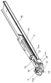
図9は、本技術の一実施の形態による電子ペンについて、下ケースを取り除いて内部構造を示す斜視図である。図10は、図9のA部を拡大して示す斜視図である。 FIG. 9 is a perspective view showing the internal structure of the electronic pen according to the embodiment of the present technology with the lower case removed. FIG. 10 is an enlarged perspective view showing a portion A of FIG.
図9、図10に示すように、2個の光源部54それぞれは、赤外光を出射する光源であるLEDと、LEDが実装されるフレキシブル配線板55とを有し、フレキシブル配線板55は、ケース51内の後方に内蔵した制御回路基板56に電気的に接続されている。また、それぞれの光源部54は、フレキシブル配線板55の光源部54のLEDを実装した面と対向する裏面側に熱伝導部が配置されている。この熱伝導部は、熱伝導性の接着部材を介して取り付けられるL字形状の金属板57を備えており、光源部54のLEDで発生した熱が金属板57に放熱されるように構成されている。これにより、LEDで発生した熱を効果的に熱伝導部に放熱することができ、LEDの長寿命化を図ることができる。
As shown in FIGS. 9 and 10, each of the two
図10に示すように、光源部54のLEDが取り付けられるL字形状の金属板57は、一方の一面がフレキシブル配線板のLEDを実装した面と対向する裏面側に配置され、他方の一面がケース51の突出部51dから離れるようにケース51の内側に向かって延長されるように折り曲げられた状態で配置されている。これにより、光源部54のLEDで発生した熱は、熱伝導部の金属板57を通して、突出部51dからケース51の内側に逃がすことができ、ユーザが電子ペン5を把持したとき、光源部54の熱を感じにくくすることが可能となる。
As shown in FIG. 10, the L-shaped
ここで、金属板57は、L字形状以外の形状でもよい。例えば、金属板57は平板形状とし、フレキシブル配線板55において、光源部54のLEDを実装した面と対向する裏面側に、金属板57の先端部側の一方の一面を取り付け、後端部側の他方の一面は、ケース51の突出部51dから離れるようにケース51の内側に向かって延長させた状態で配置される構造であってもよい。
Here, the
また、熱伝導部は、フレキシブル配線板55のLEDを実装した面と対向する裏面側に銅などの金属パターンを形成することにより設けてもよい。この場合は、フレキシブル配線板55は、熱伝導部の一部がケース51の突出部51dから離れるようにケース51の内側に向かって延長させた状態で配置される。
Moreover, you may provide a heat conductive part by forming metal patterns, such as copper, in the back surface side facing the surface which mounted LED of the
また、2個の光源部54は、ペン先52を保持する支持部材58に、金属板57を取り付けることにより配置されており、これにより光源ユニットが構成され、ケース51の先端部分に収容されている。
Further, the two
また、支持部材58の後部には、画像読取ユニット53の取付部53aがねじ(図示せず)により取り付けられ、そして画像読取ユニット53から引き出された配線部は、制御回路基板56に電気的に接続されている。
A mounting
図11は、本技術の一実施の形態による電子ペンをユーザが使用している状態を示す説明図である。図11(a)は、電子ペンをほぼ垂直に立てた状態で使用している様子を示し、図11(b)は、電子ペンを傾けた状態で使用している様子を示している。 FIG. 11 is an explanatory diagram illustrating a state in which the user is using the electronic pen according to the embodiment of the present technology. FIG. 11A shows a state in which the electronic pen is used in an upright position, and FIG. 11B shows a state in which the electronic pen is used in an inclined state.
図11に示すように、本技術による電子ペンにおいては、ケース51の先端部に突出部51dを設けていることから、電子ペン1を使用するときに、表示装置2の表示面2a、すなわち情報パターン3に対して、情報パターン3から正確な情報の読み取りが可能な傾斜角度θ、例えば45°以上の傾斜角度θになるように使用状態の傾きを規制することができる。
As shown in FIG. 11, in the electronic pen according to the present technology, since the
以上のように本技術による電子ペンにおいては、ケース51は、先端部に他の部分より径を大きくすることにより形成した突出部51dを有し、かつ突出部51dに光源部54を配置した構成であり、コンパクトな構造で光源部54を配置することができ、また突出部51dが先端部に存在するため、ユーザが電子ペンを使用するときに、適切な筆圧で電子ペンを使用することができる。
As described above, in the electronic pen according to the present technology, the
また、ケース51は、他の部分より径を大きくすることにより形成した突出部51dと、この突出部51dより後方に設けられ、かつ他の部分より径が小さくなるように形成した把持部51eとを備えた構成であり、ユーザが電子ペン5を使用するときは、他の部分より径が小さくなるように形成した把持部51eを、親指と中指もしくは薬指で把持するように持って使用することとなり、また筆圧を加えるペン先52方向には突出部51dが存在するため、使い勝手の良い電子ペンとすることができる。
Further, the
さらに、ケース51の先端部に、電子ペンを使用するときに、情報パターンに対して情報の読み取りが可能な傾斜角度になるように使用状態の傾きを規制する突出部51dを設けた構成であり、ユーザが電子ペンを持って使用するときに、電子ペンの傾きを気にすることなく使用しても、正確な情報パターンの読み取りを行うことができる。
Further, the tip of the
なお、本実施の形態においては、情報パターン3に形成された座標情報を検出するための光として、赤外光を用いる場合を例に説明したが、本技術は、赤外光を用いる形態に限定するものではない。例えば、可視光領域の青色、緑色および赤色などの波長の光を吸収、または反射する材料により、情報パターン3のマーク31を形成することにより、情報パターン3に形成された座標情報を検出するための光として、赤外光以外に可視光領域の波長の光を用いることができる。
In the present embodiment, the case where infrared light is used as the light for detecting the coordinate information formed in the
以上のように本技術は、高精細な手書き入力が可能な情報表示装置を実現する上で有用な発明である。 As described above, the present technology is a useful invention for realizing an information display device capable of high-definition handwriting input.
1,5 電子ペン
2 表示装置
2a 表示面
3 情報パターン
15,52 ペン先
31,31a,31b,31c,31d マーク
51 ケース
51a 上ケース
51b 下ケース
51c 開口部
51d 突出部
51e 把持部
52 ペン先
53 画像読取ユニット
54 光源部
55 フレキシブル配線板
56 制御回路基板
57 金属板
58 支持部材
DESCRIPTION OF
Claims (6)
前記情報パターンから情報を読み取る画像読取ユニットと、
前記光源部および画像読取ユニットを収容し、先端に、前記光源部からの光を情報パターンに照射するとともに前記画像読取ユニットが情報を読み取るための光が入射する開口部を有するケースとを備え、
前記ケースは、先端部に、ケースの他の部分より径を大きくすることにより形成した突出部を備えたことを特徴とする情報読取装置。 A light source unit that emits light to an information pattern having a plurality of optically readable marks;
An image reading unit for reading information from the information pattern;
The light source unit and the image reading unit are accommodated, and at the tip thereof, a case having an opening for irradiating the information pattern with light from the light source unit and receiving light for the image reading unit to read information,
The information reading apparatus according to claim 1, wherein the case includes a protruding portion formed by making a diameter larger than other portions of the case at a distal end portion.
Priority Applications (2)
| Application Number | Priority Date | Filing Date | Title |
|---|---|---|---|
| JP2013134588A JP2014041602A (en) | 2012-07-27 | 2013-06-27 | Information reading apparatus |
| US13/950,114 US20140028744A1 (en) | 2012-07-27 | 2013-07-24 | Information reading device |
Applications Claiming Priority (7)
| Application Number | Priority Date | Filing Date | Title |
|---|---|---|---|
| JP2012166782 | 2012-07-27 | ||
| JP2012166782 | 2012-07-27 | ||
| JP2012166781 | 2012-07-27 | ||
| JP2012166780 | 2012-07-27 | ||
| JP2012166781 | 2012-07-27 | ||
| JP2012166780 | 2012-07-27 | ||
| JP2013134588A JP2014041602A (en) | 2012-07-27 | 2013-06-27 | Information reading apparatus |
Publications (1)
| Publication Number | Publication Date |
|---|---|
| JP2014041602A true JP2014041602A (en) | 2014-03-06 |
Family
ID=49994466
Family Applications (1)
| Application Number | Title | Priority Date | Filing Date |
|---|---|---|---|
| JP2013134588A Pending JP2014041602A (en) | 2012-07-27 | 2013-06-27 | Information reading apparatus |
Country Status (2)
| Country | Link |
|---|---|
| US (1) | US20140028744A1 (en) |
| JP (1) | JP2014041602A (en) |
Cited By (1)
| Publication number | Priority date | Publication date | Assignee | Title |
|---|---|---|---|---|
| JPWO2018025467A1 (en) * | 2016-08-04 | 2019-03-22 | 株式会社ソニー・インタラクティブエンタテインメント | Information processing apparatus, information processing method, toy system, toy, and information medium |
Families Citing this family (3)
| Publication number | Priority date | Publication date | Assignee | Title |
|---|---|---|---|---|
| US9448643B2 (en) * | 2013-03-11 | 2016-09-20 | Barnes & Noble College Booksellers, Llc | Stylus sensitive device with stylus angle detection functionality |
| EP3170064B1 (en) * | 2014-07-16 | 2019-11-06 | Hewlett-Packard Development Company, L.P. | A diffusive emissive display |
| KR20230118720A (en) * | 2022-02-04 | 2023-08-14 | 삼성디스플레이 주식회사 | Display device and touch input system including the same |
Citations (11)
| Publication number | Priority date | Publication date | Assignee | Title |
|---|---|---|---|---|
| JPH06162243A (en) * | 1992-09-28 | 1994-06-10 | A D S:Kk | Pen type code reader |
| JPH07282179A (en) * | 1994-04-07 | 1995-10-27 | Olympus Optical Co Ltd | Pen type input device |
| JPH11120311A (en) * | 1997-10-13 | 1999-04-30 | Ads:Kk | Two-dimensional code and reader for the same |
| JP2003256122A (en) * | 2002-02-28 | 2003-09-10 | Kokuyo Co Ltd | Write object, handwriting input equipment, form, white board, display and transparent sheet |
| US20050254874A1 (en) * | 1999-10-25 | 2005-11-17 | Silverbrook Research Pty Ltd | Electronically controllable pen comprising a force switch |
| JP2007279822A (en) * | 2006-04-03 | 2007-10-25 | Hitachi Maxell Ltd | Handwriting input system |
| JP2007310894A (en) * | 2007-05-22 | 2007-11-29 | Kenji Yoshida | Dot pattern reading unit and mouse having it |
| JP2008204328A (en) * | 2007-02-22 | 2008-09-04 | Fuji Xerox Co Ltd | Reading device, written information processing system and program |
| JP2009181505A (en) * | 2008-01-31 | 2009-08-13 | Fuji Xerox Co Ltd | Electronic writing tool |
| US20100310299A1 (en) * | 2005-08-01 | 2010-12-09 | Silverbrook Research Pty Ltd | Electronic image-sensing pen with force sensor and removeable ink cartridge |
| WO2014017039A1 (en) * | 2012-07-27 | 2014-01-30 | パナソニック株式会社 | Information reading device |
Family Cites Families (6)
| Publication number | Priority date | Publication date | Assignee | Title |
|---|---|---|---|---|
| US8411071B2 (en) * | 2006-02-22 | 2013-04-02 | Anoto Ab | Electronic pen |
| USD595718S1 (en) * | 2008-03-11 | 2009-07-07 | Luidia, Inc. | Pen |
| USD617328S1 (en) * | 2008-12-26 | 2010-06-08 | Wacom Co., Ltd. | Electronic pen |
| EP2382523A1 (en) * | 2008-12-30 | 2011-11-02 | Sanford, L. P. | Electronic rechargeable stylus and eraser system |
| USD623187S1 (en) * | 2009-12-30 | 2010-09-07 | Sanford, L.P. | Stylus |
| USD655707S1 (en) * | 2011-08-26 | 2012-03-13 | Seiko Epson Corporation | Interactive pen |
-
2013
- 2013-06-27 JP JP2013134588A patent/JP2014041602A/en active Pending
- 2013-07-24 US US13/950,114 patent/US20140028744A1/en not_active Abandoned
Patent Citations (11)
| Publication number | Priority date | Publication date | Assignee | Title |
|---|---|---|---|---|
| JPH06162243A (en) * | 1992-09-28 | 1994-06-10 | A D S:Kk | Pen type code reader |
| JPH07282179A (en) * | 1994-04-07 | 1995-10-27 | Olympus Optical Co Ltd | Pen type input device |
| JPH11120311A (en) * | 1997-10-13 | 1999-04-30 | Ads:Kk | Two-dimensional code and reader for the same |
| US20050254874A1 (en) * | 1999-10-25 | 2005-11-17 | Silverbrook Research Pty Ltd | Electronically controllable pen comprising a force switch |
| JP2003256122A (en) * | 2002-02-28 | 2003-09-10 | Kokuyo Co Ltd | Write object, handwriting input equipment, form, white board, display and transparent sheet |
| US20100310299A1 (en) * | 2005-08-01 | 2010-12-09 | Silverbrook Research Pty Ltd | Electronic image-sensing pen with force sensor and removeable ink cartridge |
| JP2007279822A (en) * | 2006-04-03 | 2007-10-25 | Hitachi Maxell Ltd | Handwriting input system |
| JP2008204328A (en) * | 2007-02-22 | 2008-09-04 | Fuji Xerox Co Ltd | Reading device, written information processing system and program |
| JP2007310894A (en) * | 2007-05-22 | 2007-11-29 | Kenji Yoshida | Dot pattern reading unit and mouse having it |
| JP2009181505A (en) * | 2008-01-31 | 2009-08-13 | Fuji Xerox Co Ltd | Electronic writing tool |
| WO2014017039A1 (en) * | 2012-07-27 | 2014-01-30 | パナソニック株式会社 | Information reading device |
Cited By (3)
| Publication number | Priority date | Publication date | Assignee | Title |
|---|---|---|---|---|
| JPWO2018025467A1 (en) * | 2016-08-04 | 2019-03-22 | 株式会社ソニー・インタラクティブエンタテインメント | Information processing apparatus, information processing method, toy system, toy, and information medium |
| JP6995754B2 (en) | 2016-08-04 | 2022-01-17 | 株式会社ソニー・インタラクティブエンタテインメント | Information processing equipment, information processing methods, toy systems, toys, and information media |
| US11567499B2 (en) | 2016-08-04 | 2023-01-31 | Sony Interactive Entertainment Inc. | Information processing apparatus, information processing method, and information medium |
Also Published As
| Publication number | Publication date |
|---|---|
| US20140028744A1 (en) | 2014-01-30 |
Similar Documents
| Publication | Publication Date | Title |
|---|---|---|
| JP5874034B2 (en) | Display device and display control system | |
| US10365769B2 (en) | Apparatus and method for contactless input | |
| JP5468159B2 (en) | Display device and display control system | |
| US20060139338A1 (en) | Transparent optical digitizer | |
| US20110304548A1 (en) | Mouse provided with a dot pattern reading function | |
| JP5796091B2 (en) | Information display device | |
| JP2016154035A5 (en) | ||
| US20180011605A1 (en) | Apparatus and method for contactless input | |
| US20140184507A1 (en) | Display device and display control system | |
| US20150042625A1 (en) | Display control system and display devices | |
| US20140362054A1 (en) | Display control system and reading device | |
| US20140300589A1 (en) | Display device and display control system | |
| JP2014041602A (en) | Information reading apparatus | |
| US9128538B2 (en) | Optical film, display panel, and display device | |
| JP2012243201A (en) | Display device with input function | |
| US20110310072A1 (en) | Display panel and display device | |
| WO2014017039A1 (en) | Information reading device | |
| US20150035811A1 (en) | Display control system, display device, and display panel | |
| JP5957611B1 (en) | Non-contact input device and method |
Legal Events
| Date | Code | Title | Description |
|---|---|---|---|
| A711 | Notification of change in applicant |
Free format text: JAPANESE INTERMEDIATE CODE: A711 Effective date: 20141006 |
|
| A621 | Written request for application examination |
Free format text: JAPANESE INTERMEDIATE CODE: A621 Effective date: 20160217 |
|
| RD01 | Notification of change of attorney |
Free format text: JAPANESE INTERMEDIATE CODE: A7421 Effective date: 20160518 |
|
| A977 | Report on retrieval |
Free format text: JAPANESE INTERMEDIATE CODE: A971007 Effective date: 20161110 |
|
| A131 | Notification of reasons for refusal |
Free format text: JAPANESE INTERMEDIATE CODE: A131 Effective date: 20161220 |
|
| A02 | Decision of refusal |
Free format text: JAPANESE INTERMEDIATE CODE: A02 Effective date: 20170613 |