JP2014040764A - Structural component unit, structure comprising the same and method for constructing structure using the same - Google Patents
Structural component unit, structure comprising the same and method for constructing structure using the same Download PDFInfo
- Publication number
- JP2014040764A JP2014040764A JP2012253858A JP2012253858A JP2014040764A JP 2014040764 A JP2014040764 A JP 2014040764A JP 2012253858 A JP2012253858 A JP 2012253858A JP 2012253858 A JP2012253858 A JP 2012253858A JP 2014040764 A JP2014040764 A JP 2014040764A
- Authority
- JP
- Japan
- Prior art keywords
- holes
- hole
- unit
- constituting
- component
- Prior art date
- Legal status (The legal status is an assumption and is not a legal conclusion. Google has not performed a legal analysis and makes no representation as to the accuracy of the status listed.)
- Pending
Links
- 238000000034 method Methods 0.000 title claims description 40
- 238000010276 construction Methods 0.000 claims abstract description 47
- 230000000149 penetrating effect Effects 0.000 claims description 12
- 239000000470 constituent Substances 0.000 claims description 9
- 239000000463 material Substances 0.000 description 19
- 239000004567 concrete Substances 0.000 description 14
- 125000006850 spacer group Chemical group 0.000 description 10
- 238000009415 formwork Methods 0.000 description 5
- 238000009434 installation Methods 0.000 description 3
- 238000003860 storage Methods 0.000 description 3
- 239000002023 wood Substances 0.000 description 3
- 239000000853 adhesive Substances 0.000 description 2
- 230000001070 adhesive effect Effects 0.000 description 2
- 238000009826 distribution Methods 0.000 description 2
- 239000011120 plywood Substances 0.000 description 2
- 230000002787 reinforcement Effects 0.000 description 2
- 239000011347 resin Substances 0.000 description 2
- 229920005989 resin Polymers 0.000 description 2
- 230000015572 biosynthetic process Effects 0.000 description 1
- 230000037237 body shape Effects 0.000 description 1
- 210000000988 bone and bone Anatomy 0.000 description 1
- 239000004566 building material Substances 0.000 description 1
- 238000010586 diagram Methods 0.000 description 1
- 230000000694 effects Effects 0.000 description 1
- 238000009408 flooring Methods 0.000 description 1
- 238000005304 joining Methods 0.000 description 1
- 238000012423 maintenance Methods 0.000 description 1
- 238000004519 manufacturing process Methods 0.000 description 1
- 239000002184 metal Substances 0.000 description 1
- 230000003014 reinforcing effect Effects 0.000 description 1
- 239000012779 reinforcing material Substances 0.000 description 1
Images

Landscapes
- Load-Bearing And Curtain Walls (AREA)
- Steps, Ramps, And Handrails (AREA)
Abstract
Description
本発明は、構造物構成ユニット、及び構造物構成ユニットにより構成される構造物、及び構造物構成ユニットにより構造物を構築する方法に関するものであり、特に、構造物構成ユニットにより構成される建物としては、壁部、床部及び階段を構築するのに適したものである。 The present invention relates to a structure constituting unit, a structure constituted by the structure constituting unit, and a method for constructing a structure by the structure constituting unit, and particularly as a building constituted by the structure constituting unit. Is suitable for building walls, floors and stairs.
なお、本発明において使用する「構造物構成ユニット」或いは「ユニット」との用語は、一つの「構成パーツ」或いは「パーツ」を少なくとも2個重ね合わせて「エレメント」を構成し、その「エレメント」を複数段重ねて「ユニット」を構成するものである。具体的には後段にて説明する。
本発明においては、「エレメント」は、必ずしも、少なくとも2個の「構成パーツ」或いは「パーツ」を重ね合わせて構成される必要はない。
The term “structure component unit” or “unit” used in the present invention is an “element” formed by superposing at least two “component parts” or “parts”. Are stacked to form a “unit”. Specifically, it will be described later.
In the present invention, the “element” does not necessarily need to be configured by overlapping at least two “component parts” or “parts”.
従来、壁や床を構造体により構成するログハウス等は、一般に、同一サイズの丸太を井桁上に積み上げて作った建物であり、丸太に積み上げた丸太とで上から下までの通しボルトにナットで締め付けることにより全段の固定を行っている。 In the past, log houses, etc., in which walls and floors are structured by structures, are generally buildings that are made by stacking logs of the same size on a well girder, and with nuts on through bolts from top to bottom with logs stacked in a log. All stages are fixed by tightening with.
この種の壁面構造として、例えば、特許文献1(特に図5参照)、特許文献2(特に図5参照)、特許文献3(特に第3図)に開示されているような壁面用ブロックのボルトでの固定方法の記載が無く、特許文献4(特に図4)の背景技術の項目内容に「これらによると基礎上に立設されたボルトを頼りに、その上につみきを積み上げる」と記載されており、前記の従来のログハウスと同様に壁面用ブロック同士に上から下までの通しボルトにより全体を連結したものである。 As this type of wall surface structure, for example, a bolt for a wall block as disclosed in Patent Document 1 (especially see FIG. 5), Patent Document 2 (see especially FIG. 5), and Patent Document 3 (particularly FIG. 3). There is no description of the fixing method in the patent document, and the content of the background art of Patent Document 4 (particularly FIG. 4) is described as “According to these, the bolts erected on the foundation are relied on and piles are stacked thereon”. In the same manner as the conventional log house, the wall blocks are connected together by through bolts from top to bottom.
または、公知の壁面構造物としてボルトでの連結方法では、 特許文献4、特許文献7、特許文献12(特に図9)、特許文献15に開示されるような壁面の構築方法は、下から上までの構造体及び壁面材をボルトで通して固定する方法である。
Alternatively, in the connection method using a bolt as a known wall surface structure, the wall surface construction method disclosed in
または、公知の壁面構造物としてボルトでの連結方法では、特許文献5、特許文献6、特許文献8(特に図5.図6)に開示されるような壁面の構築方法は、上記の方法とは異なるが、同一のボルトの頭にナットが付いており壁面材を積みかさねながら同時にボルトでの固定を行う固定構造であるが、結果的に下から上までの構造体及び壁面材をボルトで通して固定する方法である。
Alternatively, in the connection method using bolts as a known wall surface structure, the wall surface construction method disclosed in Patent Document 5,
特許文献9(特に図4)に開示される階段構造は、多数に開口された構造本体にボルトとナットを装着し部品を一つずつずらしながら積み上げ本体より短く出たボルトにナットで固定する螺旋構造である。 The staircase structure disclosed in Patent Document 9 (particularly FIG. 4) is a spiral in which bolts and nuts are attached to a large number of open structure bodies and the parts are shifted one by one and fixed to the bolts that are shorter than the stacked body with nuts. Structure.
特許文献10(特に図1、図2、図3、図4)に開示される架梁構造はブロック本体に一つの貫通孔が開いており、その両端部は半円状の溝を設けており、ブロック本体を並べることにより、両端部の半円の溝が円状の開口になりその開口にボルトを通しその継ぎ目の上に水平補強部材を挟み込み固定して中心の貫通孔の内部に固定したナットが格納される構造であり、固定したら後に緩んだナットの締め付け調整は出来ない構造である。 The cross beam structure disclosed in Patent Document 10 (particularly FIGS. 1, 2, 3, and 4) has one through hole in the block body, and both ends thereof are provided with semicircular grooves. By arranging the block bodies, semicircular grooves at both ends become circular openings, bolts are passed through the openings, and a horizontal reinforcing member is sandwiched and fixed on the joint, and fixed inside the central through hole. It is a structure in which the nut is stored, and once it is fixed, the tightening adjustment of the loosened nut cannot be performed later.
特許文献11(特に図4)に開示される耐震構造のブロック本体に複数の貫通孔が開いており、特許文献10と類似しており、その両端部も半円状の溝を設けており、ブロック本体を並べることにより、両端部の半円の溝が円状の開口になりその開口にボルトを通すことができ、その継ぎ目と重ならない様に、ブロック本体を固定しながら大きい貫通孔の内部に固定したナットが格納される構造であり、固定したら後に緩んだナットの締め付け調整は出来ない構造である。
A plurality of through holes are opened in the block body of the earthquake-resistant structure disclosed in Patent Document 11 (particularly FIG. 4), and similar to
特許文献13(特に図8)に開示される壁工法、及びパネルに用いるブロック本体はコンクリートを打設する為の支保工であり、パネル及びブロックの貫通孔は、型棒と称する棒を貫通孔に入り、下部から上部に型棒がパネル及びブロック本体に内部を通すことによってブロックの崩壊を防ぐ効果があり、型棒でパネル及びブロック同士を固定する構造でなく、型棒を差した状態でさらに外部による調整した状態でコンクリートを打設する方法である。 The wall construction method disclosed in Patent Document 13 (particularly FIG. 8) and the block main body used for the panel are supporting works for placing concrete, and the panel and block through-holes are formed as rods called mold bars. It is effective to prevent the block from collapsing by passing the inside through the panel and block body from the bottom to the top. Furthermore, it is a method of placing concrete in a state adjusted by the outside.
特許文献14(特に図3)に開示される木造建築の請求項1で所定の四角形断面を有する木製の角材を水平に順次積み重ねるとともに上下の前記角材間を接着剤で接着し、且つ上下の位置関係にある前記角材の双方に跨って釘を打ち込むことにより固定結合して形成された木造壁を有することを特徴とする木造建築の工法である。
In
従来、ログハウスなどは、太くて丈夫で非常に重い木材をクレーン等で持ち上げて、井桁上に積み上げる方法で建築していた。 Conventionally, log houses and the like have been constructed by lifting thick, strong and very heavy wood with a crane and stacking them on a well beam.
なお従来、階段のささら桁は、専門知識と三角関数を用いて罫書き、専用工具で溝を彫り、その溝に段板を固定した物が支流であり、ささら桁は、階段の勾配に合わせ斜めに取り付け,材料は長尺のため運搬などは建築資材の専門店で行い、万が一、間違った場合、再度注文して長尺の材料を現場まで運んで貰わないといけないので非情に神経を尖らせる作業工程であった。 Traditionally, the staircase girder is a tributary with a ruled line using specialized knowledge and trigonometric functions, a groove is carved with a special tool, and a step plate is fixed in the groove. Because it is long and the material is long, transport it etc. at a building materials specialist store.If it is wrong, you have to order it again and carry the long material to the site. It was a work process.
本発明の構造物構成ユニットは、同一形状の構成ユニットを複数本の締め付けボルトにより複数ユニットを組み合わせて所望の構造物を構成するための構造物構成ユニットであり、 該構造物構成ユニットは、複数のエレメントを複数段重ねて構成されてなり、前記締め付けボルトを貫通させるための複数個の貫通穴を形成しており、該複数の貫通穴のうち少なくとも一つの貫通穴はボルト頭又はナットの収容が可能な大きな貫通穴により構成し、他の貫通穴はボルトの貫通が可能な小さな貫通穴としたことを特徴とする。 The structure constituting unit of the present invention is a structure constituting unit for constituting a desired structure by combining a plurality of units having the same shape with a plurality of fastening bolts. And a plurality of through holes for penetrating the fastening bolts are formed, and at least one of the plurality of through holes accommodates a bolt head or a nut. The other through-holes are small through-holes through which bolts can penetrate.
本発明の構造物構成ユニットは、同一形状の構成ユニットを複数本の締め付けボルトにより複数ユニットを組み合わせて所望の構造物を構成するための構造物構成ユニットであり、
該構造物構成ユニットは、一つの構成パーツを少なくとも2個重ね合わせてエレメントを作り、該エレメントを複数段重ねて構成されてなり、前記構成パーツは前記締め付けボルトを貫通させるための複数個の貫通穴を形成しており、該複数の貫通穴のうち少なくとも一つの貫通穴はボルト頭又はナットの収容が可能な大きな貫通穴により構成し、他の貫通穴はボルトの貫通が可能な小さな貫通穴としたことを特徴とする。
The structure component unit of the present invention is a structure component unit for configuring a desired structure by combining a plurality of units of the same shape with a plurality of fastening bolts.
The structure component unit is formed by superposing at least two component parts to form an element, and the elements are stacked in a plurality of stages, and the component part has a plurality of through holes for penetrating the fastening bolts. A through hole is formed, and at least one of the plurality of through holes is constituted by a large through hole capable of accommodating a bolt head or a nut, and the other through holes are small through holes capable of penetrating the bolt. It is characterized by that.
さらに、本発明の構造物構成ユニットは、2個の前記構成パーツを組み合わせる場合には、夫々の構成パーツの前後を反転させて組み合わせることにより段を構成するようにしたことを特徴とする。 Furthermore, the structure component unit of the present invention is characterized in that when two component parts are combined, a stage is configured by inverting and combining the respective component parts.
さらに、本発明の構造物構成ユニットは、前記構成パーツの前記ボルト頭又はナットを収容できる大きさの貫通穴には、該貫通穴に直行し、かつ当該構成パーツの長手方向と直行する方向のボルト締め付け穴を形成したことを特徴とする。 Furthermore, the structural component unit of the present invention has a through hole of a size that can accommodate the bolt head or nut of the component part, and is perpendicular to the through hole and in a direction perpendicular to the longitudinal direction of the component part. A bolt tightening hole is formed.
本発明の構造物は、同一形状の構成ユニットを複数本の締め付けボルトにより複数ユニットを組み合わせて所望の構造物を構成するための構造物構成ユニットにより構成される構造物であり、
該構造物を構成する構造物構成ユニットは、複数個のエレメントを複数段重ねて構成されてなり、前記締め付けボルトを貫通させるための複数個の貫通穴を形成しており、該複数の貫通穴のうち少なくとも一つの貫通穴はボルト頭又はナットの収容が可能な大きな貫通穴により構成し、他の貫通穴はボルトの貫通が可能な小さな貫通穴としており、
複数個の前記構造物構成ユニットが前記複数本の締め付けボルトにより締め付けて一体化されていることを特徴とする。
The structure of the present invention is a structure constituted by a structure constituting unit for constituting a desired structure by combining a plurality of units with a plurality of fastening bolts with the same shape constituting unit,
The structure constituting unit constituting the structure is formed by stacking a plurality of elements in a plurality of stages, forming a plurality of through holes for penetrating the fastening bolts, and the plurality of through holes At least one of the through holes is constituted by a large through hole capable of accommodating the bolt head or nut, and the other through holes are small through holes capable of penetrating the bolt,
A plurality of the structural component units are integrated by fastening with the plurality of fastening bolts.
本発明の構造物は、同一形状の構成ユニットを複数本の締め付けボルトにより複数ユニットを組み合わせて所望の構造物を構成するための構造物構成ユニットにより構成される構造物であり、
該構造物を構成する構造物構成ユニットは、一つの構成パーツを少なくとも2個重ね合わせてエレメントを作り、該エレメントを複数段重ねて構成されてなり、前記構成パーツは前記締め付けボルトを貫通させるための複数個の貫通穴を形成しており、該複数の貫通穴のうち少なくとも一つの貫通穴はボルト頭又はナットの収容が可能な大きな貫通穴により構成し、他の貫通穴はボルトの貫通が可能な小さな貫通穴としており、
複数個の前記構造物構成ユニットが前記複数本の締め付けボルトにより締め付けて一体化されていることを特徴とする。
The structure of the present invention is a structure constituted by a structure constituting unit for constituting a desired structure by combining a plurality of units with a plurality of fastening bolts with the same shape constituting unit,
The structure constituting unit constituting the structure is formed by superposing at least two constituent parts to form an element, and superposing the elements in a plurality of stages, and the constituent parts penetrate the fastening bolt. A plurality of through holes, and at least one of the plurality of through holes is formed by a large through hole that can receive a bolt head or a nut, and the other through hole is a bolt through hole. Possible through holes,
A plurality of the structural component units are integrated by fastening with the plurality of fastening bolts.
本発明の構造物を構築する方法は、同一形状の構成ユニットを複数本の締め付けボルトにより複数ユニットを組み合わせて所望の構造物を構成するための構造物構成ユニットにより構成される構造物の構築方法であり、
該構造物を構成する構造物構成ユニットは、複数個のエレメントを複数段重ねて段組みして構成し、
前記構成エレメントは前記締め付けボルトを貫通させるための複数個の貫通穴を形成しており、該複数の貫通穴のうち少なくとも一つの貫通穴はボルト頭又はナットの収容が可能な大きな貫通穴により構成し、他の貫通穴はボルトの貫通が可能な小さな貫通穴としており、
複数個の前記構造物構成ユニットを、前記複数本の締め付けボルトにより締め付けて、当該複数個の前記構造物構成ユニットを一体化することを特徴とする。
A method for constructing a structure according to the present invention is a method for constructing a structure constituted by a structure constituting unit for constituting a desired structure by combining a plurality of units of the same shape with a plurality of fastening bolts. And
The structure constituting unit constituting the structure is formed by stacking a plurality of elements in a plurality of stages,
The component element has a plurality of through holes for allowing the fastening bolts to pass therethrough, and at least one of the plurality of through holes is constituted by a large through hole capable of accommodating a bolt head or a nut. The other through holes are small through holes that allow bolts to penetrate,
A plurality of the structural component units are fastened by the plurality of fastening bolts, and the structural structural units are integrated.
本発明の構造物を構築する方法は、同一形状の構成ユニットを複数本の締め付けボルトにより複数ユニットを組み合わせて所望の構造物を構成するための構造物構成ユニットにより構成される構造物の構築方法であり、
該構造物を構成する構造物構成ユニットは、一つの構成パーツを少なくとも2個重ね合わせエレメントを作り、次いで、該エレメントを複数段重ねて段組みして構成し、
前記構成パーツは前記締め付けボルトを貫通させるための複数個の貫通穴を形成しており、該複数の貫通穴のうち少なくとも一つの貫通穴はボルト頭又はナットの収容が可能な大きな貫通穴により構成し、他の貫通穴はボルトの貫通が可能な小さな貫通穴としており、
複数個の前記構造物構成ユニットを、前記複数本の締め付けボルトにより締め付けて、当該複数個の前記構造物構成ユニットを一体化することを特徴とする。
A method for constructing a structure according to the present invention is a method for constructing a structure constituted by a structure constituting unit for constituting a desired structure by combining a plurality of units of the same shape with a plurality of fastening bolts. And
The structure constituting unit constituting the structure is formed by superposing at least two component parts to form an element, and then stacking the elements in a plurality of stages.
The component part has a plurality of through holes for allowing the fastening bolts to pass therethrough, and at least one of the plurality of through holes is constituted by a large through hole capable of accommodating a bolt head or a nut. The other through holes are small through holes that allow bolts to penetrate,
A plurality of the structural component units are fastened by the plurality of fastening bolts, and the structural structural units are integrated.
この発明によれば、小型の形状を利用し建築物である構造体のである、壁、床、階段などの形成を構築でき材料の運搬による流通コストを抑えることができ、仕様される主たる材料が木材であることにより、自然素材がそのままであって優しい環境を造り出すことができる。 According to the present invention, it is possible to construct a wall, a floor, a staircase, etc., which is a structure that is a building using a small shape, and to suppress distribution costs due to transportation of materials. By being made of wood, it is possible to create a gentle environment with natural materials intact.
本発明は、建築物の壁、床、階段などの構造物を、複数個のエレメントをボルトとナットで強固に連結させ、構造体の本体と骨となるボルトで強度を保ち、さらに連結方法を規則化して重ねることで、構造体の部品は小型だが強固な壁面を構成する積層固定方法を提案するものである。 In the present invention, a structure such as a building wall, a floor, or a staircase is constructed by firmly connecting a plurality of elements with bolts and nuts, maintaining the strength with bolts that become the main body of the structure and bones, and further connecting methods It proposes a stacking and fixing method in which the parts of the structure are compact but constitute a strong wall by regularizing and stacking.
近年、人工林の保護とエコブームで間伐材の利用促進をはかり、小型の形状を利用し更に形状を簡素化し製造工程のコスト軽減を提案するものである。 In recent years, the use of thinned wood has been promoted through protection of planted forests and an eco-boom, and it has been proposed to use a small shape to further simplify the shape and reduce manufacturing costs.
構造物は、その機能面からすれば、通常、屋根、壁、床、天井、階段から構成されると言っても良い。その際、例えば、一直線の階段のささら桁は4m以上あるので、それを如何に簡単に構成できるかが課題であった。そこで本発明は、簡単ではあるが規則的な構築方法での部品は短い状態で現地に運び、設置箇所に階段構造を構築する方法を提案するものである。その他の構造物である屋根、壁、床、天井においても同様のことが言える。 It can be said that a structure is usually composed of a roof, a wall, a floor, a ceiling, and a staircase in terms of its functional aspects. At that time, for example, since there are 4 m or more of straight stairs in a straight staircase, it was a problem how to construct it easily. Therefore, the present invention proposes a method for carrying parts in a short but regular construction method to the site in a short state and constructing a staircase structure at the installation location. The same can be said for roofs, walls, floors, and ceilings, which are other structures.
なお、階段のささら桁の構築方法では材料を水平に重ねて一定方向にずらす構築方法なので、専門知識と三角関数は必要とせずその方法を提案するものである。 In addition, since the construction method of the sag of the staircase is a construction method in which the materials are horizontally stacked and shifted in a certain direction, this method is proposed without requiring specialized knowledge and trigonometric functions.
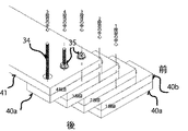
次に、本発明を実施するための形態について図面を参照して具体的に説明する。本明細書の説明においては、「上」「下」の方向は図面上の上下関係と同じ方向で説明し、「前」「後」の方向は、後述するエレメント或いはユニットを積み上げていく方向での手前側(図1、図5では右側)を「前」方向として説明する。 Next, embodiments for carrying out the present invention will be specifically described with reference to the drawings. In the description of the present specification, “up” and “down” directions are described in the same direction as the vertical relationship on the drawing, and “front” and “rear” directions are directions in which elements or units described later are stacked. The front side (right side in FIGS. 1 and 5) is described as the “front” direction.
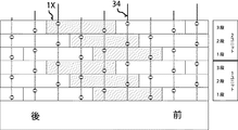
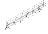
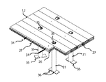
本発明の実施例では、エレメントを複数段重ねて1ユニットを構成し、そのユニットを上下前後方向(前後方向は、図1では左右方向に一致)に複数積み重ねて平面構造物を形成したものである。それを3段重ねて1ユニットを構成した状態の側面図であり、その1段部分をエレメントとして左右方向に複数接合して平面構造物を形成したものである。 In the embodiment of the present invention, a plurality of elements are stacked to form one unit, and a plurality of the units are stacked in the up-and-down and front-and-rear direction (the front-and-rear direction coincides with the left-and-right direction in FIG. 1) to form a planar structure. is there. It is a side view of a state in which one unit is configured by stacking three stages, and a planar structure is formed by joining a plurality of one-stage portions in the left-right direction as elements.
本発明においては、構造物の構成要素であるエレメントを、1つのパーツとして構成する場合と、2つのパーツから構成する場合とを説明している。エレメントを上下に2つのパーツから構成した状態の構造体は、各パーツをローアーパーツ1aとアッパーパーツ1bと称し、本実施例の説明においては、それを「二個一式構造物構成部品」と呼ぶことがある(図5のハッチング部分)。
In this invention, the case where the element which is a component of a structure is comprised as one part, and the case where it comprises from two parts are demonstrated. In the structure in which the element is composed of two parts at the top and bottom, each part is referred to as a
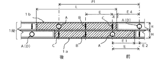
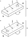
エレメントは、貫通孔が6個、開いておりその順番は、下部(ローアーパーツ1aの部分)は前(図3右)より大口径孔a、小口径孔b、小口径孔cと開いている。上部(アッパーパーツ1bの部分)は貫通孔が、前(図3右)より小口径c、小口径b、大口径aと開いている。
The element has six through-holes open, and the lower part (
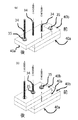
次いで、2段目のエレメントを前(図1右)からボルト孔を一つ後退した位置に連結し、前記同様に連結固定方法の大口径の貫通孔で連結固定を行い次のエレメントも同様に穴の同位置で連結固定を繰り返すことで構造体部品が斜め状に壁、床及び連結される、従って、二個一式構造物構成部品の構築方法同様に連結固定方法を繰り返すことで任意で面積及び長さの追加ができる。 Next, the second stage element is connected to the position where one bolt hole is retracted from the front (right side of FIG. 1), and is connected and fixed with a large-diameter through hole in the same way as described above. By repeatedly connecting and fixing at the same position of the hole, the structural parts are diagonally connected to the wall, floor, and, therefore, the area can be arbitrarily determined by repeating the connecting and fixing method in the same way as the construction method of two-piece structure components. And length can be added.
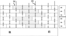
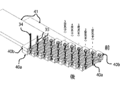
本発明の実施例では、2つのパーツを接合して1つのエレメントを構成し、そのエレメントを複数段重ねて1ユニットを構成し、そのユニットを上下前後方向(前後方向は、図4では左右方向に一致)に複数積み重ねて平面構造物を形成したものである。図4では、ローアーパーツ1aとアッパーパーツ1bを接合してユニットの1段部分(エレメント)として構成し、それを3段重ねて1ユニットを構成した状態の側面図であり、その1段部分をエレメントとして左右方向に複数接合して平面構造物を形成したものであり、その詳細の組み合わせの状態が図5の側面図である。本発明においては、このようにローアーパーツ1aとアッパーパーツ1bの2パーツを接合してユニットの1段部分(エレメント)として構成し、それを複数段重ねて構造体を形成するエレメントを指して、本実施例の説明においては「二個一式構造物構成部品」と呼ぶことがある(図5のハッチング部分)。
In the embodiment of the present invention, two parts are joined to form one element, and a plurality of the elements are stacked to form one unit, and the unit is arranged in the vertical direction (the forward and backward direction is the horizontal direction in FIG. 4). A planar structure is formed by stacking a plurality of the same. In FIG. 4, the
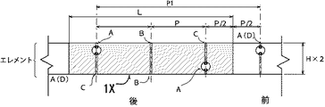
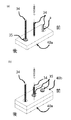
二個一式構造物構成部品を構成するパーツとしてのローアーパーツ1aは、貫通孔が3個a,b及びc開いておりその順番は、前(図5右)より大口径孔a、小口径孔b、小口径孔cと開いている。次に貫通孔が、前(図5右)より小口径c、小口径b、大口径aと開いているアッパーパーツ1bを、ローアーパーツ1aの3個の穴a,b及びcと同位置に、重ね合わせる。その際、大口径の貫通孔a内にナットを収容して2つのパーツを連結固定する。次いで、2段目のローアーパーツ1aを前(図5右)からボルト孔を一つ後退した位置に連結し、前記同様に連結固定方法の大口径の貫通孔で連結固定を行い次の1bアッパーパーツも同様に穴の同位置で連結固定を繰り返すことで構造体部品が斜め状に壁、床及び連結される。
The
従って、二個一式構造物構成部品を用いてこの連結固定方法を繰り返すことで任意で面積及び長さの追加ができる。構造物の構成要素であるエレメントを、1つのパーツとして構成する場合は、二個一式構造物構成部品が一つの部材から構成される状態を思い描けば理解は容易である。 Therefore, an area and a length can be arbitrarily added by repeating this connection and fixing method using a set of two structural components. In the case where an element that is a component of a structure is configured as one part, it is easy to understand if a state in which a set of two structural components is composed of one member is envisioned.
なお、その場合は、エレメントを1つのパーツとして構成する場合も、二個一式構造物構成部品の場合も、貫通孔の穴同士の間隔(p)は全て同じでなければならない。 In this case, the interval (p) between the holes of the through holes must be the same regardless of whether the element is configured as one part or in the case of a two-piece structure component.
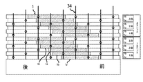
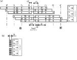
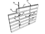
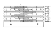
以下、本発明の種々の実施例を図面に基づいて説明する。図4は、本発明の二個一式構造物構成部品の基本配列を示した図であり穴が3個の貫通孔(大、小、小)で構成する部品を強固に連結固定する状態を示した図であり、図5はその詳細を示した図である。 Hereinafter, various embodiments of the present invention will be described with reference to the drawings. FIG. 4 is a view showing a basic arrangement of two-piece structure component parts according to the present invention, showing a state in which the parts constituted by three through holes (large, small and small) are firmly connected and fixed. FIG. 5 is a diagram showing the details thereof.
まず、最初に1aローアーパーツの3つの穴にボルト34を通し(a)大口径の穴内にてナット35で固定し、1bアッパーパーツの3つの穴に前記同位地のボルト34を通し(a)大口径の穴内にてナット35で固定することで図4の1段目の固定を完了させたものである(図5参照)。
First, the
次に、2段目の連結は一つボルトを後退させた位置より2段目も1段目同様に1aローアーパーツと1bアッパーパーツの固定し完了させたものである(図4参照)。 Next, in the second stage connection, the 1a lower part and the 1b upper part are fixed and completed in the same way as the first stage from the position where one bolt is retracted (see FIG. 4).
さらに、3段目も2段目の同様な方法で固定したものであり、この3段を基本的な構造で一つのユニットとして形成しとものである(図4参照)。 Further, the third stage is fixed in the same manner as the second stage, and the third stage is formed as one unit with a basic structure (see FIG. 4).
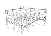
また、1段を構成する際に同時にコーナー部材(図6及び図7参照)を用い構築したユニットを連結することで壁、床の構造体の構築ができるのである。図4及び図12はコーナー部材を用いて構築した側面図である。 In addition, when constructing one stage, a wall and floor structure can be constructed by connecting units constructed using corner members (see FIGS. 6 and 7) at the same time. 4 and 12 are side views constructed using corner members.
なお、コーナー部材を使用しないで二個一式構造物階段構成部品40を斜めに段の単体で積み上げて行くことにより階段の構造体も容易に構築できるのである(図14参照)。
It should be noted that a staircase structure can be easily constructed by stacking two sets of staircase
また、二個一式構造物構成ユニットを構成する際に二個一式構造物構成部品の1aローアーパーツと1bアッパーパーツの積み方の順番を逆にしたものであり、連結箇所が集中し連結ボルトが長尺の仕様である(図20参照)。 Also, when constructing a two-piece structure component unit, the order of stacking the 1a lower part and the 1b upper part of the two-piece structure component parts is reversed, and the connection points are concentrated and the connection bolts are This is a long specification (see FIG. 20).
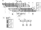
次に、壁、床に用いる二個一式構造物構成ユニットのコーナー部品の切断する場所の説明に二個一式構造物構成部品2を使用し図面を用いて説明する(図6参照)。
Next, the description will be made with reference to the drawing, using the two-
二個一式構造物構成部品2の6個の貫通孔のコーナーカットは、貫通孔イ〜チの中心部のニとホの間で行うためには、コーナー部で互い違いに連結させるので進行方向(前)より1ブロックの1aローアーパーツは、穴から(穴間のピッチp÷2)−(二個一式構造物構成部品2の(厚さD)÷2)で計算されるc2((穴間のピッチp÷2)−(二個一式構造物構成部品2の(厚さD)÷2)=c2)をおいて切断される。次に、1ブロックの1bアッパーパーツは、穴から(穴のピッチp÷2)+(二個一式構造物構成部品2(厚さD)÷2)で計算されるc1((穴のピッチp÷2)+(二個一式構造物構成部品2(厚さD)÷2)=c1)で切断される。次に、2ブロックの1aローアーパーツは、穴から(穴のピッチp÷2)−(二個一式構造物構成部品2(厚さ)÷2)で計算されるc2で切断する。
In order to cut the corners of the six through holes of the two-piece set
よって、コーナー部品52とコーナー部品53とコーナー部品56がコーナーの角で互い違いに連結することができる。
Therefore, the
なお、前記コーナー部品のコーナー部品3枚51,53,55の前に後ろのコーナー部品3枚52、54、56を連結することで本発明の二個一式構造の連結配列パターンを崩すこと無く井桁状に積み上げることができる(図12参照)ので、ログハウス等の構築に容易である。
By connecting the three
前記コーナー部品の接続部は互い違いに連結される形状になっているが取り合いの無い場合は穴間のピッチp÷2で切断すると端面が一直線になる。よって、床の構築、間取りの開口はこの方式で行うと作業的な失敗は最小限に抑えることができる。 The connection parts of the corner parts are alternately connected to each other, but when there is no connection, the end faces become straight when cut at a pitch p / 2 between the holes. Therefore, if this method is used for floor construction and floor opening, work failures can be minimized.
また、本発明の二個一式構造物構成ユニットの1ユニットは6枚積みなので前記の3枚分のコーナー部品の51,52,53,54,55,56は残り3枚分のコーナー部品57,58,59,60,61,62、と同一部品である(図6参照)。
In addition, since one unit of the two-piece structure component unit of the present invention is stacked, the above three
このように、構成されており構造は複雑だがコーナー部品は6種類の部品でコーナー連結が可能である(図6参照)。 As described above, the structure is complicated, but the corner parts can be connected to the corner with six kinds of parts (see FIG. 6).
さらに、本発明の二個一式構造物構成部品2の6個の貫通孔のコーナーカット(図6参照)に二個一式構造物構成部品1(3個の貫通孔)で代用できる部分を引くことで残りの部品の二個一式構造物構成部品1(3個の貫通孔)を用いてコーナー部品としての使用可能である(図7参照)。
Furthermore, draw a portion that can be substituted by the two-piece structure component 1 (three through-holes) in the corner cut (see FIG. 6) of the six through-holes of the two-
よって、二個一式構造物構成ユニットのコーナー部のカット及び垂直処理は切断した部品の端材は反対側に使用するので無駄な端材が発生しにくい仕組みであり、より幅の短い物にも対応できるものである(図6、図7、図12、図20、図21参照)。 Therefore, the cut and vertical processing of the corner part of the two-piece structure component unit is a mechanism in which the end material of the cut part is used on the opposite side, so that wasteful end material is less likely to occur, and even for items with a shorter width (See FIGS. 6, 7, 12, 20, and 21).
だが、本発明を用いて大面積の平面を構築する場合には、二個一式構造物構成部品1より接続箇所が少ない二個一式構造物構成部品2を使用するのが好ましいので運搬時の状況など考慮し二個一式構造物構成部品の長さの選択が可能である。
However, when constructing a large-area plane using the present invention, it is preferable to use the two-
次に、この発明に好ましい状態での二個一式構造物構成ユニットか形成される二個一式構造物構成部品の穴とその本体の形状の状態につい二個一式構造物構成部品1の図面を用いて説明する。(図8及び図9参照)。
Next, the drawings of the two-
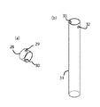
なお、二個一式構造物構成部品の基本的な穴が3個の貫通孔(大、小、小)及び6個の貫通孔(大、小、小、大、小、小)は、縦方向と横方向に構築可能な仕様になっており、縦使いは貫通孔4,5,6,8にボルト34を貫通孔より大口径の穴3にパイプワッシャー28を挿入し固定を行う貫通孔である。なお、横使いは貫通孔3、7,9にボルト34を通し大口径の穴3に固定したナット35を納める貫通孔である。
In addition, the basic holes of the two-piece set of structural components are three through holes (large, small, small) and six through holes (large, small, small, large, small, small) in the vertical direction. The vertical use is a through-hole that is fixed by inserting a
なお、3個の貫通孔を持つ二個一式構造物構成部品1の長さLは、L=P×3であり、二個一式構造物構成部品2は、L2=P×6である(図8及び図9参照)。
The length L of the two-
そして、隣り合うパーツとの連結部の位置E1,E2については、P=E1+E2であり,推奨位置はE1=(P/4)×3である。なお、Pは穴間のピッチである。 And about the position E1, E2 of the connection part with an adjacent part, it is P = E1 + E2, and a recommended position is E1 = (P / 4) * 3. P is a pitch between holes.
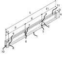
二個一式構造物構成部品1に全周に溝10、11が掘られており部品同士に連結する際にスペーサーブロック26、26を挟み込む溝であり、スペーサーブロックを挟み込むことで構造体同士のずれを防止でき、さらに、スペーサーブロックを組み込む際にコーキング材を注入することで外部からの風雨の進入を抑える効果がある。
このように、二個一式構造物構成部品に溝を設けることで部品同士の接続箇所の互換性を無くし向き方向の自由度を広げ穴の順番に寄る制限で構造体の構築できる機能を持ち、かつ部品の簡略化を計り二個一式構造物構成部品1で幅広い構造物を構築できるものである。
In this way, by providing a groove in the set of two structural components, the compatibility of the connection places between the parts is lost, the degree of freedom in the direction of direction is expanded, and the structure can be constructed with the restriction of the order of the holes, In addition, by simplifying the parts, a wide range of structures can be constructed with the two-in-one
なお、使用されるボルト34は大口径の貫通孔から次の大口径の貫通孔は内で連結させる為、穴で連結は二枚ずつの締め付けとなり使用するボルトの長さは(二個一式構造物構成部品の高さH×3)−パイプワッシャーの内径+(ワッツシャーとナットの掛かり代×2)=ボルト長さになる。よって、ボルト自体の長さは長尺にならない為、部品調達、部品管理も容易にでき、流通手段も二個一式構造物構成部品も同様に小型である。
In addition, since the
次に、本発明の二個一式構造物構成ユニットの構築方法を具体的な実施の体形に基づいて例で詳しく説明する(図6及び図12参照)なお、二個一式構造物構成部品にパイプワッシャー28を挿入しボルト、ナットで仮固定した状態で準備した構造体部品の使用を前提とした説明とする。
Next, the construction method of the two-piece structure constituent unit of the present invention will be described in detail by way of example based on the specific embodiment (see FIGS. 6 and 12). The description is based on the premise of using a structural component prepared with the
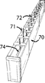
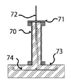
まずは、基礎となる設置箇所をコンクリート打設する前に、固定用アンカーボルト72をコンクリート型枠用アンカーボルト保持治具にて固定し、コンクリートを打設し基礎と固定可能な状態で構築するか(図22及び図23参照)、基礎の打設後にアンカーを打ちボルトにて固定用のボルト設置する方法、どちらかの方法で構築前に固定部材を施しコーナーより順番に前記の通り、コーナー部材51をパイプワッシャー内で固定し、10に溝にスペーサーブロック26を挟み込み、ローアーパーツ1aを固定しスペーサーブロック26を同じく挟み込み、51の端材の52を固定し1段目の溝11にスペーサーブロック27をボルト間に挟み込み連結箇所に止水材(コーキング材など)を塗布し同じくボルト貫通部に止水材(コーキング材など)を充填し、次にアッパーパーツ1bの列もローアーパーツ1aの列と同様に固定することで、二個一式構造物構成部品の一段目を形成する。
First, before placing the foundation installation place into the concrete, is the
次に、進行方向の前より一つ後退した穴より前記の一段目の形成方法をと同じく行い2段目の形成する、3段目も2段目と同様に行う。 Next, the third step is performed in the same manner as the second step, in the same manner as in the first step formation method, from the hole that has been retreated by one from the front in the traveling direction.
このようにして、前記3段目の構築で二個一式構造物構成1ユニットが形成される、
なお、この構築方法の連結及び接続箇所の縦方向は不規則に連結される為、強固に連結可能である。
In this way, one unit of two structures is formed by the construction of the third stage.
In addition, since the connection of this construction method and the vertical direction of the connection place are connected irregularly, it can be connected firmly.
さらに、二個一式構造物構成部品を連結させることで二個一式構造物構成ユニットの大きさや広さは無限大に構築が可能である。 Furthermore, by connecting two sets of structural components, the size and width of the two sets of structural components can be constructed infinitely.
なお平面に対する面積が多い場合で長尺の構造体で構築する方法として進行方向(前)大径、小径、小径とし、その前後に同じ順番の大径、小径、小径を追加することができ、3個の次に追加できる数は6個(二個一式構造物構成部品2)で次は9個である、つまり3の倍数で追加が可能である(図8及び図9参照)。 In addition, as a method of constructing a long structure with a large area with respect to the plane, it is possible to add a large diameter, small diameter, small diameter in the same order before and after the traveling direction (front) large diameter, small diameter, small diameter, The number that can be added next to three is six (a set of two structural components 2) and the next is nine, that is, it can be added in multiples of three (see FIGS. 8 and 9).
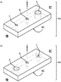
前記の二個一式構造物構成ユニットの構築方法を構築する際にパイプワッシャー28を31に変更しパイプワッシャー31の下部を束及び基礎などにつけることで水平構築が可能である。
Horizontal construction is possible by changing the
また、前記パイプワッシャー31を接地させる際にライナーやスペーサーなので水平調整し、パイプワッシャー31の上部の穴よりコンクリート及び樹脂性の接着剤などを流し固定させることで床のさらに強度のある床の構築が可能である。
Further, when the
さらに、前記水平構築された二個一式構造物構成ユニットに合板を貼ることにより、更に強力な床の構築が可能である。 Furthermore, a more powerful floor can be constructed by attaching plywood to the horizontally constructed two-piece structure structure unit.
同様に、壁構造に合板を貼ることにより、耐震性に優れた強固な壁の構築が可能である。 Similarly, by attaching plywood to the wall structure, it is possible to construct a strong wall with excellent earthquake resistance.
二個一式構造物構成ユニットの固定箇所の穴は脱着可能なキャップをすることにより、雨風の進入防止などができると共に、ボルトの緩みなどのメンテナンスも可能に構成できる。 By attaching a detachable cap to the holes at the fixing points of the two-piece structure component unit, it is possible to prevent rain and wind from entering and to perform maintenance such as loosening of bolts.
次に、本発明の二個一式構造物構成ユニットの構築方法を利用し階段ささら桁の構築の方法を図面で説明する。図14〜図19は前記の発明に係る実施例の構築方法である、図4〜図13のコーナーカット部品の説明を除いたものを用い本発明の二枚組み合わせた構造体部品の穴を一つずつずらし二枚組み合わせた二個一式構造物構成部品を固定し次も穴を一つずつずらし二枚組み合わせた二個一式構造物構成部品を固定する構築方法を利用したものである。よって平面構築の二個一式構造物構成ユニットの構築方法に、コーナー部品を除いた構築方法である。 Next, a method for constructing a staircase girder using the construction method for a two-piece set structure unit of the present invention will be described with reference to the drawings. FIGS. 14 to 19 show the construction method of the embodiment according to the invention described above, except for the explanation of the corner cut parts in FIGS. This is a construction method in which two sets of structural components that are combined by shifting two pieces are fixed, and then two holes are combined one by one, and two sets of structural components that are combined are fixed. Therefore, it is a construction method in which the corner parts are excluded from the construction method of the two-piece structure structure unit of the planar construction.
また、二個一式構造物構成部品の二個一式構造物階段構成部品は、進行方向(前)大径、小径、小径でありも同じである。 Further, the two-piece set structure step component of the two-piece set structure component is the same in the traveling direction (front) large diameter, small diameter, and small diameter.
また、複数枚の二個一式構造物構成部品を並べ垂直に積み上げていく平面構造物と違い独立して斜めに上昇していく二個一式構造物階段構成部品は前後の連結が無く作業性も向上させることができるのである。 Also, unlike a planar structure in which multiple two-piece structure components are arranged and stacked vertically, a two-piece structure staircase component that rises diagonally independently has no front-rear connection and is easy to work with. It can be improved.
なお、二個一式構造物階段構成部品は二個一式構造物構成部品と同じく穴の数が3つ以上で構成される二個一式構造物構成ユニットの部品であるが穴の追加については二個一式構造物構成部品の穴の追加方法と異なり中心の小口径の穴を基準にし(前)大浩径の穴(後)小口径の穴をベースに前後一つずつ追加可能である、つまり階段構造体の用いる穴の数は前後の取り合いが発生しないので3個以上の穴で数は奇数であれば構築可能である(図14参照)。 The two-piece structure staircase component is the same as the two-piece structure component, but it is a two-piece structure component unit composed of three or more holes. Unlike the method of adding holes in a set of structural components, it is possible to add one hole at a time in front and back, based on a hole with a small diameter in the center (front) and a hole with a large diameter (rear) with a small diameter. Since the number of holes used in the structure does not cause a back-and-forth contact, construction is possible if the number of holes is three or more and the number is an odd number (see FIG. 14).
本発明の二個一式構造物構成部品の穴配列と同様の貫通孔を形成した二個一式構造物階段構成部品を構築することによって平面構造体同様に強固な連結を可能にするのである。ただし、穴の追加数は、二個一式構造物構成部品は3の倍数、二個一式構造物階段構成部品は奇数であり固定方法も大きい穴のパイプワッシャー内で固定する方法で無く、大きい穴にナットを格納する方法だが原理は同じである。 By constructing a two-piece structure staircase component in which a through hole similar to the hole arrangement of the two-piece structure component of the present invention is formed, it is possible to connect as firmly as a planar structure. However, the number of additional holes is a multiple of 3 for two-piece structure components, and the odd number for two-piece structure stair components, and the fixing method is not a method of fixing in a pipe washer with a large hole. However, the principle is the same.
よって、二個一式構造物階段構成部品の貫通孔の数は増えるほど構造体同士の連結枚数も増え、強度が増し本発明の二個一式構造物構成ユニットの構築方法を用いることで、二枚ずつ構造体の内部で固定することが可能であり強固に連結固定でき穴の数については適宜選択することができる(図14参照)。 Therefore, as the number of through-holes in the two-piece structure staircase component increases, the number of connections between the structures also increases, the strength increases, and the two-piece structure structure unit construction method of the present invention is used. The number of holes can be selected as appropriate (see FIG. 14).
次に、本発明の二個一式構造物構成ユニットの構築方法を利用した階段ささら桁の寸法の設定方法を図面で説明する(図14参照)。例で、蹴上(H)200mm、踏み面(D)250とし、使用する材料は25mmの木製の材料とする、蹴上(H)200÷厚さ25=8枚として、1ブロック2枚ずつずらすので、8枚÷2=4なので、踏み面(D)250÷4=62.5よって、部品の貫通孔の穴の間隔は62.5mmである。この方法だと三角関数など専門知識が無くても階段ささら桁の製作を容易にでき作業効率を向上できるものである Next, a method for setting the dimensions of the staircase spar using the construction method of the two-piece structure component unit of the present invention will be described with reference to the drawings (see FIG. 14). In this example, the kick-up (H) is 200 mm, the tread surface (D) is 250, and the material to be used is a wooden material of 25 mm. The kick-up (H) is 200 ÷ thickness is 25 = 8. Since the shift is 8 pieces / 2 = 4, the tread surface (D) 250 ÷ 4 = 62.5. Therefore, the interval between the through holes of the component is 62.5 mm. With this method, it is possible to easily produce stair-sag girders and improve work efficiency without special knowledge such as trigonometric functions.
次に、本発明の二個一式構造物構成ユニットの構築方法を利用した階段構造の施工方法を図16(例は二個一式構造物階段構成部品3個の貫通孔)の具体的な実施の体形に基づいて例で詳しく説明する。 Next, the construction method of the staircase structure using the construction method of the two-piece structure constituent unit of the present invention is shown in FIG. 16 (example is three through-holes of the two-piece structure structure staircase component). An example will be described in detail based on the body shape.
床に固定用のボルト34と床下地81と土台となる補強材82をボルト配置位置に穴を開け固定できる伸ばした状態で、下地と土台を固定用のボルト34で締付固定した上に仕上げした状態が最も好ましい。
With the
次に階段構造体のボルト貫通孔の穴の数、下準備しておき二個一式構造物階段構成部品のボルト貫通孔の中心を基準に階段上り元(前)よりローアーパーツ40a大径(前)、小径(中心)、小径(後)の方向でボルトを通し接地固定をし、小径(後)にナット35で固定し次にアッパーパーツ40b小径(前)、小径(中心)、大径(後)の方向で同位置にかさねる。その際にローアーパーツ40aを小径(後)に固定したナット35がアッパーパーツ40bの大径(後)の穴に格納された状態になり中心と前方のボルトにナット34で固定することで本発明の1段目を形成することができる(図16参照)。
Next, the number of holes in the bolt through hole of the staircase structure, prepared in advance, the
次に、2段目に使用するローアーパーツ40aの大径(前)、小径(中心)、小径(後)の後方の貫通孔にボルト34を最大に出した状態にナット35でローアーパーツ40aをはさみ込み固定する。
Next, the
前記、ボルトを取付けた40aを1段目の中心から一つ後退したボルト34を二段目の中心にボルトローアーパーツ40aにボルトとナットを取り付けた構造体部品を大径(前)、小径(中心)の方向でボルトを貫通し結合させアッパーパーツ40bを小径(前)、小径(中心)、大径(後)の方向でかさねる。その際にローアーパーツ40aを小径(後)に固定したナット35がアッパーパーツ40bの大径(後)の穴に格納された状態になり中心と前方のボルトにナット34で固定することで本発明の2段目の形成ができる(図17(b)参照)。
The structure part in which a bolt and a nut are attached to a bolt
3段目以降は上記同様に連結箇所の中心より一つ後退したボルト34を中心(基準)とし2段目と同じ連結方法を行う。
In the third and subsequent stages, the same connection method as in the second stage is performed with the
このように積み重ねて連結固定する途中で階段の段板構造部品41を入れ替えることで本発明の二個一式構造物構成ユニットの階段を容易に構築できるものである(図18参照)。
In this way, the staircase of the two-piece structure component unit of the present invention can be easily constructed by replacing the staircase
いずれにしろ本発明に係る構造体の平面及び階段の施工方法と形状においては、色々な分野で利用でき、利用目的に応じて材質を樹脂、金属、コンクリートなど形成することも可能であり、あらゆる建造物において広く利用できるのである。
Anyway, in the construction method and shape of the plane and staircase of the structure according to the present invention, it can be used in various fields, and the material can be formed of resin, metal, concrete, etc. according to the purpose of use. It can be widely used in buildings.
(1X)二個一式構造物構成部品(6箇所の貫通孔を持った構造体)
(1)二個一式構造物構成部品(3箇所の貫通孔を持った構造体)
(1a)二個一式構造物構成部品ローアーパーツ
(1b)二個一式構造物構成部品アッパーパーツ
(2)二個一式構造物構成部品(6箇所の貫通孔を持った構造体)
(2a)二個一式構造物構成部品ローアーパーツ
(2b)二個一式構造物構成部品アッパーパーツ
(3)大口径の貫通孔(パイプワッシャー格納孔)と横方向連結用貫通孔
(4)縦方向連結用貫通孔
(5)縦方向連結用貫通孔
(6)縦方向連結用貫通孔
(7)横方向連結用貫通孔
(8)縦方向連結用貫通孔
(9)横方向連結用貫通孔
(10)位置決めスペーサー用溝(横連結)
(11)位置決めスペーサー用溝(縦連結)
(12)大口径の貫通孔(パイプワッシャー格納孔)と横方向連結用貫通孔
(13)縦方向連結用貫通孔
(14)縦方向連結用貫通孔
(15)縦方向連結用貫通孔
(16)横方向連結用貫通孔
(17)縦方向連結用貫通孔
(18)横方向連結用貫通孔
(19)大口径の貫通孔(パイプワッシャー格納孔)と横方向連結用貫通孔
(20)縦方向連結用貫通孔
(21)縦方向連結用貫通
(22)縦方向連結用貫通孔
(23)横方向連結用貫通孔
(24)縦方向連結用貫通孔
(25)横方向連結用貫通孔
(26)スペーサーブロック小(横連結)
(27)スペーサーブロック大(縦連結)
(28)パイプワッシャー(壁用)
(29)連結固定用ボルト貫通孔
(30)連結固定用ボルト貫通孔
(31)ロングパイプワッシャー(床用)
(32)連結固定用ボルト貫通孔
(33)連結固定用ボルト貫通孔
(34)連結固定ボルト
(35)連結固定ナット、ワッシャーセット
(36)床施工用レベル調整用スペーサー (40)二個一式構造物階段構成部品(3箇所の貫通孔を持った階段用構造体)
(40a)二個一式構造物階段構成部品アッパーパーツ
(40b)二個一式構造物階段構成部品ローアーパーツ
(41)二個一式構造物階段構成部品の段板付き(3箇所の貫通孔を持った階段用構造体二個一式構造物階段構成部品)
(51)コーナー部品,2a,1段目、前方部品(62と同じ)
(52)コーナー部品,2a,1段目、後方部品(61と同じ)
(53)コーナー部品,2b,1段目、後方部品(60と同じ)
(54)コーナー部品,2b,1段目、前方部品(59と同じ)
(55)コーナー部品,2a,2段目、前方部品(58と同じ)
(56)コーナー部品,2a,2段目、後方部品(57と同じ)
(57)コーナー部品,2b,2段目、前方部品(56と同じ)
(58)コーナー部品,2b,2段目、後方部品(55と同じ)
(59)コーナー部品,2a,3段目、前方部品(54と同じ)
(60)コーナー部品,2a,3段目、後方部品(53と同じ)
(61)コーナー部品,2b,3段目、前方部品(52と同じ)
(62)コーナー部品,2b,3段目、後方部品(51と同じ)
(63)コーナー部品,1a,1段目、前方部品(1b,3段目、後方部品)
(64)コーナー部品,1a,1段目、後方部品(1b,3段目、前方部品)
(65)コーナー部品,1b,1段目、前方部品(1a,3段目、後方部品)
(66)コーナー部品,1b,1段目、後方部品(1a,3段目、前方部品)
(67)コーナー部品,1a,2段目、前方部品(1b,2段目、後方部品)
(68)コーナー部品,1a,2段目、後方部品(1b,2段目、前方部品)
(70)コンクリート型枠
(71)コンクリート型枠用アンカーボルト保持治具
(72)構造用物構成ユニット固定用アンカーボルト
(73)コンクリート基礎
(74)コンクリート基礎の鉄筋
(80)仕上げ材(フローリングなど)
(81)下地材(床の下地)
(82)土台(階段設置用補強土台)
(a)大口径の穴
(b)小口径の穴
(c)小口径の穴
(d)大口径の穴
(p)穴と穴の幅
(p1)3個の穴の幅(基本の貫通孔)
(c1)コーナーカットの幅
(c2)コーナーカットの幅
(E) 穴と穴の幅
(E1)連結部の幅
(E2)連結部の幅
(L)1の全長
(L2)2の全長
(H)構成パーツの高さ
(D) パーツの幅
(K)階段の蹴上寸法
(F)階段の踏み面寸法
(1X) Two set of structural components (structure with six through holes)
(1) A set of two structural components (structure with three through holes)
(1a) Two sets of structural components Lower parts
(1b) Two sets of structural components upper parts
(2) A set of two structural components (structures with six through holes)
(2a) Two sets of structural components Lower parts
(2b) Two piece set structure component upper part
(3) Large-diameter through hole (pipe washer storage hole) and lateral connection through hole
(4) Longitudinal connecting through hole
(5) Vertical connection through hole
(6) Vertical connection through hole
(7) Lateral connection through hole
(8) Longitudinal connecting through hole
(9) Lateral connection through hole
(10) Groove for positioning spacer (horizontal connection)
(11) Groove for positioning spacer (vertical connection)
(12) Large-diameter through hole (pipe washer storage hole) and lateral connection through hole
(13) Vertical connection through hole
(14) Longitudinal connection through hole
(15) Vertical connection through hole
(16) Lateral connection through hole
(17) Vertical connection through hole
(18) Lateral connection through hole
(19) Large-diameter through hole (pipe washer storage hole) and lateral connection through hole
(20) Vertical connection through hole
(21) Longitudinal connection through
(22) Longitudinal connection through hole
(23) Lateral connection through hole
(24) Vertical connection through hole
(25) Lateral connection through hole
(26) Spacer block small (horizontal connection)
(27) Spacer block size (vertical connection)
(28) Pipe washer (for walls)
(29) Connection fixing bolt through hole
(30) Connection fixing bolt through hole
(31) Long pipe washer (for floor)
(32) Connection fixing bolt through hole
(33) Connection fixing bolt through hole
(34) Connection fixing bolt
(35) Connection fixing nut, washer set
(36) Level adjustment spacer for floor construction (40) Two-stage structure staircase component (staircase structure with three through holes)
(40a) Two-piece set structure staircase component upper part
(40b) Two sets of structural staircase components Lower parts
(41) Staircase components with two sets of staircase components (two staircase structures with three through holes)
(51) Corner part, 2a, 1st stage, front part (same as 62)
(52) Corner parts, 2a, 1st stage, rear parts (same as 61)
(53) Corner parts, 2b, 1st stage, rear parts (same as 60)
(54) Corner parts, 2b, 1st stage, front parts (same as 59)
(55) Corner part, 2a, 2nd stage, front part (same as 58)
(56) Corner parts, 2a, 2nd stage, rear parts (same as 57)
(57) Corner part, 2b, 2nd stage, front part (same as 56)
(58) Corner parts, 2b, 2nd stage, rear parts (same as 55)
(59) Corner part, 2a, 3rd stage, front part (same as 54)
(60) Corner parts, 2a, 3rd stage, rear parts (same as 53)
(61) Corner part, 2b, 3rd stage, front part (same as 52)
(62) Corner part, 2b, 3rd stage, rear part (same as 51)
(63) Corner part, 1a, 1st stage, front part (1b, 3rd stage, rear part)
(64) Corner part, 1a, 1st stage, rear part (1b, 3rd stage, front part)
(65) Corner part, 1b, 1st stage, front part (1a, 3rd stage, rear part)
(66) Corner part, 1b, 1st stage, rear part (1a, 3rd stage, front part)
(67) Corner part, 1a, 2nd stage, front part (1b, 2nd stage, rear part)
(68) Corner part, 1a, 2nd stage, rear part (1b, 2nd stage, front part)
(70) Concrete formwork
(71) Anchor bolt holding jig for concrete formwork
(72) Anchor bolt for fixing structural component unit
(73) Concrete foundation
(74) Reinforcement of concrete foundation
(80) Finishing materials (flooring etc.)
(81) Base material (floor base)
(82) Base (Reinforcement base for staircase installation)
(a) Large-diameter hole
(b) Small-diameter hole
(c) Small-diameter hole
(d) Large-diameter hole
(p) Hole and hole width
(p1) Width of 3 holes (basic through hole)
(c1) Corner cut width
(c2) Corner cut width
(E) Hole and hole width
(E1) Link width
(E2) Link width
(L) Total length of 1
(L2) Total length of 2
(H) Height of component parts
(D) Part width
(K) Stair lift
(F) Stair tread dimensions
Claims (8)
該構造物構成ユニットは、複数のエレメントを複数段重ねて構成されてなり、前記締め付けボルトを貫通させるための複数個の貫通穴を形成しており、該複数の貫通穴のうち少なくとも一つの貫通穴はボルト頭又はナットの収容が可能な大きな貫通穴により構成し、他の貫通穴はボルトの貫通が可能な小さな貫通穴としたことを特徴とする構造物構成ユニット。 A structural unit for configuring a desired structure by combining a plurality of units with the same shape of the structural unit with a plurality of fastening bolts,
The structural component unit is configured by stacking a plurality of elements in a plurality of stages, forming a plurality of through holes for penetrating the tightening bolts, and at least one of the plurality of through holes penetrating. A structure constituting unit characterized in that the hole is constituted by a large through hole capable of accommodating a bolt head or a nut, and the other through hole is a small through hole capable of penetrating the bolt.
該構造物を構成する構造物構成ユニットは、複数個のエレメントを複数段重ねて構成されてなり、前記締め付けボルトを貫通させるための複数個の貫通穴を形成しており、該複数の貫通穴のうち少なくとも一つの貫通穴はボルト頭又はナットの収容が可能な大きな貫通穴により構成し、他の貫通穴はボルトの貫通が可能な小さな貫通穴としており、
複数個の前記構造物構成ユニットが前記複数本の締め付けボルトにより締め付けて一体化されていることを特徴とする構造物。 It is a structure constituted by a structure constituting unit for constituting a desired structure by combining a plurality of units with a plurality of fastening bolts of the same shape constituting unit,
The structure constituting unit constituting the structure is formed by stacking a plurality of elements in a plurality of stages, forming a plurality of through holes for penetrating the fastening bolts, and the plurality of through holes At least one of the through holes is constituted by a large through hole capable of accommodating the bolt head or nut, and the other through holes are small through holes capable of penetrating the bolt,
A structure in which a plurality of the structural component units are integrated by fastening with the plurality of fastening bolts.
該構造物を構成する構造物構成ユニットは、一つの構成パーツを少なくとも2個重ね合わせてエレメントを作り、該エレメントを複数段重ねて構成されてなり、前記構成パーツは前記締め付けボルトを貫通させるための複数個の貫通穴を形成しており、該複数の貫通穴のうち少なくとも一つの貫通穴はボルト頭又はナットの収容が可能な大きな貫通穴により構成し、他の貫通穴はボルトの貫通が可能な小さな貫通穴としており、
複数個の前記構造物構成ユニットが前記複数本の締め付けボルトにより締め付けて一体化されていることを特徴とする構造物。 It is a structure constituted by a structure constituting unit for constituting a desired structure by combining a plurality of units with a plurality of fastening bolts of the same shape constituting unit,
The structure constituting unit constituting the structure is formed by superposing at least two constituent parts to form an element, and superposing the elements in a plurality of stages, and the constituent parts penetrate the fastening bolt. A plurality of through holes, and at least one of the plurality of through holes is formed by a large through hole that can receive a bolt head or a nut, and the other through hole is a bolt through hole. Possible through holes,
A structure in which a plurality of the structural component units are integrated by fastening with the plurality of fastening bolts.
該構造物を構成する構造物構成ユニットは、複数個のエレメントを複数段重ねて段組みして構成し、
前記構成エレメントは前記締め付けボルトを貫通させるための複数個の貫通穴を形成しており、該複数の貫通穴のうち少なくとも一つの貫通穴はボルト頭又はナットの収容が可能な大きな貫通穴により構成し、他の貫通穴はボルトの貫通が可能な小さな貫通穴としており、
複数個の前記構造物構成ユニットを、前記複数本の締め付けボルトにより締め付けて、当該複数個の前記構造物構成ユニットを一体化することを特徴とする構造物を構築する方法。 It is a construction method of a structure constituted by a structure constituting unit for constituting a desired structure by combining a plurality of units with a plurality of fastening bolts of the same shape constituting unit,
The structure constituting unit constituting the structure is formed by stacking a plurality of elements in a plurality of stages,
The component element has a plurality of through holes for allowing the fastening bolts to pass therethrough, and at least one of the plurality of through holes is constituted by a large through hole capable of accommodating a bolt head or a nut. The other through holes are small through holes that allow bolts to penetrate,
A method for constructing a structure, comprising: fastening a plurality of the structural component units with the plurality of fastening bolts to integrate the structural component units.
該構造物を構成する構造物構成ユニットは、一つの構成パーツを少なくとも2個重ね合わせてエレメントを作り、次いで、該エレメントを複数段重ねて段組みして構成し、
前記構成パーツは前記締め付けボルトを貫通させるための複数個の貫通穴を形成しており、該複数の貫通穴のうち少なくとも一つの貫通穴はボルト頭又はナットの収容が可能な大きな貫通穴により構成し、他の貫通穴はボルトの貫通が可能な小さな貫通穴としており、
複数個の前記構造物構成ユニットを、前記複数本の締め付けボルトにより締め付けて、当該複数個の前記構造物構成ユニットを一体化することを特徴とする構造物を構築する方法。 It is a construction method of a structure constituted by a structure constituting unit for constituting a desired structure by combining a plurality of units with a plurality of fastening bolts of the same shape constituting unit,
The structure constituting unit constituting the structure is configured by superposing at least two constituent parts to form an element, and then superposing and stacking the elements in a plurality of stages.
The component part has a plurality of through holes for allowing the fastening bolts to pass therethrough, and at least one of the plurality of through holes is constituted by a large through hole capable of accommodating a bolt head or a nut. The other through holes are small through holes that allow bolts to penetrate,
A method for constructing a structure, comprising: fastening a plurality of the structural component units with the plurality of fastening bolts to integrate the structural component units.
Priority Applications (1)
| Application Number | Priority Date | Filing Date | Title |
|---|---|---|---|
| JP2012253858A JP2014040764A (en) | 2012-11-20 | 2012-11-20 | Structural component unit, structure comprising the same and method for constructing structure using the same |
Applications Claiming Priority (1)
| Application Number | Priority Date | Filing Date | Title |
|---|---|---|---|
| JP2012253858A JP2014040764A (en) | 2012-11-20 | 2012-11-20 | Structural component unit, structure comprising the same and method for constructing structure using the same |
Related Parent Applications (1)
| Application Number | Title | Priority Date | Filing Date |
|---|---|---|---|
| JP2012182160A Division JP5201286B1 (en) | 2012-08-21 | 2012-08-21 | Structure constituting unit, structure constituted by structure constituting unit, and method for constructing structure by structure constituting unit |
Publications (1)
| Publication Number | Publication Date |
|---|---|
| JP2014040764A true JP2014040764A (en) | 2014-03-06 |
Family
ID=50393205
Family Applications (1)
| Application Number | Title | Priority Date | Filing Date |
|---|---|---|---|
| JP2012253858A Pending JP2014040764A (en) | 2012-11-20 | 2012-11-20 | Structural component unit, structure comprising the same and method for constructing structure using the same |
Country Status (1)
| Country | Link |
|---|---|
| JP (1) | JP2014040764A (en) |
Cited By (1)
| Publication number | Priority date | Publication date | Assignee | Title |
|---|---|---|---|---|
| JP6832597B1 (en) * | 2020-07-28 | 2021-02-24 | 株式会社アルフデザイン | Wall structure and construction method of wall structure |
-
2012
- 2012-11-20 JP JP2012253858A patent/JP2014040764A/en active Pending
Cited By (2)
| Publication number | Priority date | Publication date | Assignee | Title |
|---|---|---|---|---|
| JP6832597B1 (en) * | 2020-07-28 | 2021-02-24 | 株式会社アルフデザイン | Wall structure and construction method of wall structure |
| WO2022024558A1 (en) * | 2020-07-28 | 2022-02-03 | 株式会社アルフデザイン | Wall surface structure and method for constructing wall surface structure |
Similar Documents
| Publication | Publication Date | Title |
|---|---|---|
| CN109642424B (en) | Connecting system and method for prefabricated volume building modules | |
| US7882665B2 (en) | Construction configurations and construction methods of steel houses | |
| JP2012012881A (en) | Earthquake resistant structure for building | |
| JP3690437B2 (en) | Seismic reinforcement structure for existing buildings | |
| JP5607384B2 (en) | Construction method for beam-column joints | |
| KR100769154B1 (en) | Precast concrete column and its manufacturing method for buckling prevention of panel zone and improvement of construction with lower part | |
| JP2003105861A (en) | High-rise buildings using HFC columns, HFC beams, etc. | |
| JP4590373B2 (en) | Structural wall | |
| JP4400833B2 (en) | Seismic reinforcement method and reinforcement piece | |
| JP4446401B2 (en) | Seismic reinforcement method and reinforcement piece | |
| JP2008266902A (en) | Wall unit and shear wall | |
| JP2014040764A (en) | Structural component unit, structure comprising the same and method for constructing structure using the same | |
| JP5201286B1 (en) | Structure constituting unit, structure constituted by structure constituting unit, and method for constructing structure by structure constituting unit | |
| JP5650383B2 (en) | Multistage braided joint shaft | |
| KR100963586B1 (en) | End Connection of Unit Modular System, Modular Unit and Manufacturing Method of Modular Unit | |
| JP2008002091A5 (en) | ||
| EP0460004B1 (en) | Space frame and module for its construction | |
| JP4285427B2 (en) | Seismic reinforcement structure for buildings | |
| JP2022000564A (en) | Execution method of work before concrete placing of reinforced concrete structure, construction method of reinforced concrete structure, and formwork for reinforced concrete placing | |
| JP2920490B2 (en) | Method of manufacturing panel-joined caisson and panel-joined caisson | |
| JP2007284918A (en) | Horizontally laid body and wooden structure | |
| JPH0525997B2 (en) | ||
| JP3802633B2 (en) | Unit building and its construction method | |
| JPH0833016B2 (en) | Concrete assembling basement skeleton structure | |
| JP2017044009A (en) | Base structure of base-isolated building |