JP2014040714A - Awning device - Google Patents
Awning device Download PDFInfo
- Publication number
- JP2014040714A JP2014040714A JP2012182317A JP2012182317A JP2014040714A JP 2014040714 A JP2014040714 A JP 2014040714A JP 2012182317 A JP2012182317 A JP 2012182317A JP 2012182317 A JP2012182317 A JP 2012182317A JP 2014040714 A JP2014040714 A JP 2014040714A
- Authority
- JP
- Japan
- Prior art keywords
- end side
- fixed
- sheet
- elastic body
- rotatable
- Prior art date
- Legal status (The legal status is an assumption and is not a legal conclusion. Google has not performed a legal analysis and makes no representation as to the accuracy of the status listed.)
- Pending
Links
- 238000004804 winding Methods 0.000 claims abstract description 24
- 230000008602 contraction Effects 0.000 abstract description 8
- 238000005452 bending Methods 0.000 description 11
- 230000007246 mechanism Effects 0.000 description 6
- 230000005540 biological transmission Effects 0.000 description 3
- 230000001681 protective effect Effects 0.000 description 3
- 230000002093 peripheral effect Effects 0.000 description 2
- 230000008878 coupling Effects 0.000 description 1
- 238000010168 coupling process Methods 0.000 description 1
- 238000005859 coupling reaction Methods 0.000 description 1
- 230000000694 effects Effects 0.000 description 1
- 238000000034 method Methods 0.000 description 1
- 230000037072 sun protection Effects 0.000 description 1
Images
Landscapes
- Building Awnings And Sunshades (AREA)
Abstract
Description
本発明は、日よけや雨よけのために建築物の壁面から片持ちでシート体を張り出すように設けるオーニング装置に関する。 The present invention relates to an awning device provided so as to project a sheet body in a cantilevered manner from a wall surface of a building for sun protection and rain protection.
片持ち型のオーニング装置は、壁面位置の巻き取り装置に巻き取られたシート体の先端側を、伸びるようにバネで付勢される屈曲したアームにより前方に伸ばすことで、シート体を張り出した状態に保持するものが広く用いられている。シート体を収納する際には、シート体を電動又は手動で巻き取り、アームを強制的に折り畳むことでシート体を収納する。 The cantilever type awning device extends the sheet body by extending the front end side of the sheet body wound around the winding device at the wall surface position by a bent arm that is biased by a spring so as to extend. What is kept in a state is widely used. When the sheet body is stored, the sheet body is wound by electric or manual winding, and the arm is forcibly folded.
ところで、上述した構造を有するオーニング装置はアームがバネで伸びるように付勢されているので、ある程度強い風が吹くとバネが縮んでシート体が膨らんだり、左右にねじれたりすることがある。
本発明は、このような問題に鑑みて、片持ち型のオーニング装置において、風でシート体が膨らんだり、左右にねじれたりすることが発生しにくい構造を提供することを課題とする。
By the way, since the awning device having the above-described structure is urged so that the arm is extended by a spring, when a strong wind blows to some extent, the spring may be contracted and the sheet body may swell or twist left and right.
In view of such a problem, an object of the present invention is to provide a structure in which a sheet body is less likely to swell or twist left and right due to wind in a cantilever type awning device.
上記課題を解決するために、本発明は次のような構成を有する。
請求項1に記載の発明は、先端側の縁部が棒体で支持されるシート体と、前記シート体の基端側を巻き取る、巻き取り軸が水平になるように壁面に固定される巻き取り装置と、基端側が鉛直軸に回転可能に壁面に固定され、先端側が鉛直軸に回転可能に前記シート体の棒体に固定される、駆動手段により基端と先端を結ぶ線上に沿って伸縮する第一伸縮体と、基端側が前記第一伸縮体の固定位置から水平に一定距離を置いて、鉛直軸に回転可能に壁面に固定され、先端側が鉛直軸に回転可能に前記シート体の棒体に固定される駆動手段により基端と先端を結ぶ線上に沿って伸縮する第二伸縮体とを有し、前記第一伸縮体と第二伸縮体とが同じ長さのときに、前記第一伸縮体の基端側の固定位置と、前記第二伸縮体の基端側の固定位置の中央を通る鉛直面に対して、前記第一伸縮体と前記第二伸縮体とが対称になるように形成されるオーニング装置である。なお、巻き取り装置は、ゼンマイやバネ、ゴムなどの弾性体によりシート体を巻き取る方向に付勢するか、モーターにより巻き取り軸を回転させるものが用いられる。
In order to solve the above problems, the present invention has the following configuration.
The invention according to claim 1 is fixed to the wall surface so that the edge of the front end side is supported by a rod, and the take-up shaft that takes up the base end side of the sheet is horizontal. A winding device and a base end side is fixed to a wall surface so as to be rotatable about a vertical axis, and a front end side is fixed to a rod body of the sheet body so as to be rotatable about a vertical axis. A first telescopic body that expands and contracts, and a base end side that is horizontally fixed from a fixed position of the first telescopic body, is fixed to a wall surface so as to be rotatable about a vertical axis, and the front end side is rotatable about the vertical axis A second elastic body that expands and contracts along a line connecting the base end and the distal end by a driving means fixed to the rod of the body, and when the first elastic body and the second elastic body have the same length The center of the base end side fixing position of the first telescopic body and the base end side fixing position of the second telescopic body That with respect to a vertical plane, the a first stretch body and the second elastic member is a Awning devices formed to be symmetrical. As the winding device, a device that urges the sheet body in the winding direction by an elastic body such as a spring, a spring, or rubber, or rotates a winding shaft by a motor is used.
請求項2に記載の発明は、前記オーニング装置において、前記第一伸縮体と前記第二伸縮体の間に、基端側が鉛直軸に回転可能に壁面に固定され、先端側が鉛直軸に回転可能に前記シート体の棒体に固定される、鉛直軸回りに屈曲できる屈曲アームが設けられるものである。
請求項3に記載の発明は、前記オーニング装置において、前記第一伸縮体の先端側と前記第二伸縮体の先端側とは同じ鉛直軸に対して回転可能に前記シート体の棒体に固定されるものである。
請求項4に記載の発明は、前記オーニング装置において、前記第一伸縮体と第二伸縮体の組み合わせを1ユニットとして、一つの前記シート体の棒体に対して2ユニット以上が並列に設けられるものである。
請求項5に記載の発明は、前記オーニング装置において、前記巻き取り装置には、巻き取り軸の回転を固定するブレーキ手段が設けられるものである。
According to a second aspect of the present invention, in the awning device, a proximal end side is fixed to a wall surface so as to be rotatable about a vertical axis and a distal end side is rotatable about the vertical axis between the first elastic body and the second elastic body. Further, a bending arm which is fixed to the rod body of the sheet body and which can be bent around the vertical axis is provided.
According to a third aspect of the present invention, in the awning device, the distal end side of the first stretchable body and the distal end side of the second stretchable body are fixed to the rod body of the sheet body so as to be rotatable about the same vertical axis. It is what is done.
According to a fourth aspect of the present invention, in the awning device, the combination of the first elastic body and the second elastic body is used as one unit, and two or more units are provided in parallel with respect to a single rod body of the sheet body. Is.
According to a fifth aspect of the present invention, in the awning device, the winding device is provided with brake means for fixing rotation of the winding shaft.
請求項1に記載の発明は、第一伸縮体と第二伸縮体とを同じだけ伸ばすことで、シート体の棒体を平行に移動させることができる。そして、第一伸縮体と第二伸縮体の移動を止めることで、シート体の棒体は移動が拘束されることになるので、風でシート体に多少の負荷がかかっても第一伸縮体と第二伸縮体とは縮まないので、シート体の風による膨らみや左右のねじれなどが生じることを抑制することができる。
請求項2に記載の発明は、屈曲アームを設けることで、下方へ回転しようとする力を分散できるので、シート体を伸ばしたときの剛性を高くすることができる。特に、屈曲アームの片持ち梁としての強度を高くすれば、第一伸縮体と第二伸縮体を簡素化することができる。
請求項3に記載の発明は、第一伸縮体と第二伸縮体の先端を合致させることで、第一伸縮体と第二伸縮体とでトラス構造が形成され強度を高めることができる。
請求項4に記載の発明は、前記第一伸縮体と第二伸縮体の組み合わせたユニットを並列に配置することで、幅の広いシート体を支持することが可能となる。
請求項5に記載の発明は、第一伸縮体と第二伸縮体とを伸ばした状態で固定するとともに、ブレーキ手段によりシート体の巻き取り軸の回転も固定することで、シート体が風で膨らむことをより確実に抑制することができる。
In the first aspect of the invention, the rod body of the sheet body can be moved in parallel by extending the first stretchable body and the second stretchable body by the same amount. And by stopping the movement of the first elastic body and the second elastic body, the movement of the rod body of the sheet body is restrained, so even if a slight load is applied to the sheet body by the wind, the first elastic body And the second stretchable body are not contracted, so that it is possible to prevent the sheet body from being swollen by wind and twisting left and right.
According to the second aspect of the present invention, since the force to rotate downward can be dispersed by providing the bending arm, the rigidity when the sheet body is extended can be increased. In particular, if the strength of the bending arm as a cantilever is increased, the first elastic body and the second elastic body can be simplified.
In the invention according to claim 3, a truss structure is formed by the first stretchable body and the second stretchable body, and the strength can be increased by matching the tips of the first stretchable body and the second stretchable body.
In the invention according to claim 4, it is possible to support a wide sheet body by arranging in parallel the unit in which the first stretchable body and the second stretchable body are combined.
The invention according to claim 5 fixes the first stretchable body and the second stretchable body in an extended state, and also fixes the rotation of the take-up shaft of the sheet body by the brake means, so that the sheet body is winded. Inflating can be more reliably suppressed.
以下、本発明の実施の形態について、図面を参照しながら説明する。
(実施形態1)
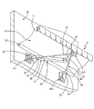
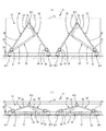
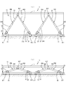
図1に実施形態1に係るオーニング装置Xの一部を表す斜視図を示し、図2(a)にオーニング装置Xの開いた状態を示す底面図を示し、図2(b)はオーニング装置Xの閉じた状態を示す底面図を示す。図1はオーニング装置Xを左右に分離したうちの片側を示している。
オーニング装置Xは、シート体10、巻き取り装置20、第一伸縮体30、第二伸縮体40、屈曲アーム50とを有する。第一伸縮体30、第二伸縮体40、屈曲アーム50は、これらで一つのユニットを構成するものであり、左右対称に2ユニット設けられる。
シート体10は遮光性及び防水性を有するシートから構成され、先端に真っ直ぐな状態に保持するための角パイプからなる棒体11が設けられている。
巻き取り装置20は、シート体10を基端側から巻き取り軸となる芯棒に巻き取る装置であり、ゼンマイにより芯棒を常にシート体10を巻き取る方向に付勢している。即ち、シート体10の先端側に力を加えない状態ではシート体10は巻き取り装置20に巻き取られた状態となる。巻き取り装置20は芯棒が水平になるように建物の壁面Wに固定される。
Hereinafter, embodiments of the present invention will be described with reference to the drawings.
(Embodiment 1)
FIG. 1 is a perspective view showing a part of the awning device X according to the first embodiment, FIG. 2A is a bottom view showing the opened state of the awning device X, and FIG. The bottom view which shows the closed state of is shown. FIG. 1 shows one side of the awning device X separated into left and right.
The awning device X includes a
The
The
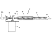
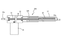
第一伸縮体30、第二伸縮体40はほぼ同じ構造を有する伸縮する棒状体である。図3に第一伸縮体30の模式的な断面図を示す。第一伸縮体30は、回転棒31、移動パイプ32、筐体33、保護パイプ34、制御モーター35、回転伝達機構36から構成される。回転棒31は全ネジボルトにより形成される。移動パイプ32は、内周に回転棒31に係合する雌ネジが形成されたパイプ体からなり、回転棒31の先端側から係合する。筐体33は、回転棒31を基端側で回転可能に保持する直方体状の箱体である。保護パイプ34は、回転棒31を囲い保護するパイプ体であり、移動パイプ32を内周面で移動可能に挿入できる内径を有する。制御モーター35は、筐体33の下面に固定されるサーボモーターやステッピングモーターのような回転位置の制御が可能なモーターから構成される。回転伝達機構36は、制御モーター35の回転を回転棒31に伝達するフェースギアにより形成される。なお、回転伝達機構36は、フェースギアの他にウォームギアや傘歯車を用いてもよく、さらに、制御モーター34の回転軸が回転棒31と一致したり平行であったりする場合は、カップリングや平歯車等を用いることができる。このような構造により、制御モーター35を正転又は反転させることで全ネジボルトからなる回転棒31が回転し、これに係合する雌ネジが形成された移動パイプ32は、回転方向に応じて先端側に移動したり、基端側に移動したりすることができる。
The first
筐体33の基端側の面には上下に開口した筒体33aが設けられ、当該筒体33a部分が壁面WにブラケットB1を介して鉛直な回転軸に回転可能に固定される。また、移動パイプ32の先端にも上下に開口したリング体32aが設けられる。第一伸縮体30のリング体32aは下方にずれた位置に設けられるとともに、第二伸縮体40のリング体32aは上方にずれた位置に設けられることで、基端側に設けられるリング体33aの固定高さを一致させた状態において、回転棒31、移動パイプ32の水平を保ったまま、第一伸縮体30のリング体32aと、第二伸縮体40のリング体32aとを重ねることができるようになっている。
第二伸縮体40も基端側でリング体33aが壁面WにブラケットB1から水平に一定距離をおいたブラケットB2を介して第一伸縮体30と同じ高さにおいて鉛直な回転軸に回転可能に固定される。また、第一伸縮体30と第二伸縮体40の先端側のリング体32a同士は、第一伸縮体30と第二伸縮体40とが同じ長さになった状態で、シート体10の棒体11にブラケットB3を介して鉛直な回転軸に回転可能に固定されている。
第一伸縮体30、第二伸縮体40の制御モーター35は、図示しない制御装置により制御され、すべての第一伸縮体30及び第二伸縮体40とが常に同じ長さを維持しながら伸縮するように制御されている。
A
The second
The
屈曲アーム50は、第一アーム51、第二アーム52とから形成される。第一アーム51は十分な荷重に耐えることができる角パイプからなり、基端側は、ブラケットB1の第一伸縮体30の上側に第一伸縮体の基端側と同じ鉛直な回転軸に回転可能に固定される。第二アーム52も十分な荷重に耐えることができる角パイプからなり、先端側は、ブラケットB3の第一伸縮体30、第二伸縮体40の上側に、第一伸縮体30、第二伸縮体40の先端側と同じ鉛直な回転軸に回転可能に固定される。また、第一アーム51の先端側と第二アーム52の基端側とは互いに鉛直な回転軸周りに回転可能に固定される。なお、屈曲アーム50は図1、図2(a)に示すように伸びきることはなく、屈曲した状態で使用され、折りたたんだときの角度が小さくできるように第一アーム51と第二アーム52を連結する回転軸は第二アーム52において、屈曲した内側に寄って設けられている。
The bending
次に、以上のような構成を有するオーニング装置Xの使用方法、作用効果について説明する。通常、使用しないときには、図2(b)に示すように、第一伸縮体30、第二伸縮体40を縮めて、シート体10の先端側を壁面Wに近接させた状態とする。そして、シート体10を広げるときには、第一伸縮体30、第二伸縮体40を伸ばして、図1、図2(a)のような状態とする。この状態において、シート体10の先端は第一伸縮体30、第二伸縮体40により基端側への移動が抑制されているので、風でシート体10に力が加わってもシート体10の先端は移動することがなく、シート体10が左右にねじれたりすることがない。また、シート体10の荷重は屈曲アーム50が支持しているので、第一伸縮体30、第二伸縮体40は荷重を受ける必要がなく、強度的に簡易な構造とすることができる。
Next, a method of using the awning device X having the above-described configuration and operational effects will be described. Usually, when not in use, as shown in FIG. 2 (b), the first
(実施形態2)
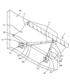
図4に実施形態2に係るオーニング装置Yの一部を表す斜視図を示し、図5(a)にオーニング装置Yの開いた状態を示す底面図を示し、図5(b)はオーニング装置Yの閉じた状態を示す底面図を示す。図4はオーニング装置Xを左右に分離したうちの片側を示している。実施形態2に係るオーニング装置Yの実施形態1に係るオーニング装置Xとの違いは、第一伸縮体30A、第二伸縮体40Aの強度を増して、屈曲アーム50を省略した点である。
(Embodiment 2)
FIG. 4 is a perspective view showing a part of the awning device Y according to the second embodiment, FIG. 5A is a bottom view showing the opened state of the awning device Y, and FIG. The bottom view which shows the closed state of is shown. FIG. 4 shows one side of the awning device X separated into the left and right. The difference between the awning device Y according to the second embodiment and the awning device X according to the second embodiment is that the strength of the first
図6に、オーニング装置Yの第一伸縮体30Aの模式的な断面図を示す。なお、第二伸縮体40Aの構造も、実施形態1の第二伸縮体と同様に先端のリング32aの位置を除いて同じである。第一伸縮体30Aは、実施形態1に係る第一伸縮体30において、移動パイプ32の外側に、十分な荷重に耐えることができる角パイプからなる第二移動パイプ37を移動パイプ32に一体に固定し、保護パイプ34Aを、第二移動パイプ37を第二移動パイプ37を内周面で移動可能に保持できる形状を有する角パイプに代えたものである。
実施形態2に係るオーニング装置Yは、以上のような構成を有するので、屈曲アーム50を省略でき、外観をシンプルなものとすることができる。
In FIG. 6, typical sectional drawing of 30 A of 1st expansion-contraction bodies of the awning apparatus Y is shown. In addition, the structure of 40 A of 2nd elastic bodies is the same except the position of the
Since the awning device Y according to the second embodiment has the above-described configuration, the bending
なお、上記実施形態において巻き取り装置10に回転を固定する電磁ブレーキを設けてもよい。この場合、シート体10の移動を停止した状態で電磁ブレーキをかけておけば、巻き取り装置10のゼンマイに抗する強い風が吹いてシート体10が膨らもうとした場合でも、電磁ブレーキによりシート体10の基端側は固定されるので、強い風が吹いてもシート体10が膨らむことを抑制できる。また、上記実施形態では巻き取り装置10はゼンマイによりシート体を巻き取るように形成しているが、モーターによって巻き取るようにし、第一伸縮体30、第二伸縮体40と同期してシート体の繰り出し量を調節するようにしてもよい。
さらに、上記実施形態では、第一伸縮体30、第二伸縮体40は雄ネジと雌ネジによる伸縮機構により伸縮するように形成されているが、伸びた位置で固定できる構造であれば、ボールネジ、リニアモーター、リンク機構、エアシリンダ、油圧シリンダなど種々の伸縮機構を採用することができる。
また、上記実施形態では一組の第一伸縮体30、第二伸縮体40を含むユニットを2つ並列に並べているが、当該ユニットは一つでもよく、3つ以上を並列に並べてもよい。
それから、上記実施形態では一ユニットを構成する第一伸縮体30と第二伸縮体40の先端は同じ回転軸で回転可能に固定されているが、第一伸縮体30と第二伸縮体とが左右対称な状態を維持する限りにおいて、第一伸縮体30と第二伸縮体40の先端側の回転軸もシート体10の棒体11に沿ってずれた位置に設けられていてもよい。
In the above embodiment, the winding
Furthermore, in the said embodiment, although the 1st expansion-
In the above embodiment, two units including a pair of the first
And in the said embodiment, although the front-end | tip of the 1st expansion-
X、Y オーニング装置
10 シート体
11 棒体
20 巻き取り装置
30、30A 第一伸縮体
40、40A 第二伸縮体
50 屈曲アーム
X,
Claims (5)
前記シート体の基端側を巻き取る、巻き取り軸が水平になるように壁面に固定される巻き取り装置と、
基端側が鉛直軸に回転可能に壁面に固定され、先端側が鉛直軸に回転可能に前記シート体の棒体に固定される、駆動手段により基端と先端を結ぶ線上に沿って伸縮する第一伸縮体と、
基端側が前記第一伸縮体の固定位置から水平に一定距離を置いて、鉛直軸に回転可能に壁面に固定され、先端側が鉛直軸に回転可能に前記シート体の棒体に固定される駆動手段により基端と先端を結ぶ線上に沿って伸縮する第二伸縮体とを有し、
前記第一伸縮体と第二伸縮体とが同じ長さのときに、前記第一伸縮体の基端側の固定位置と、前記第二伸縮体の基端側の固定位置の中央を通る鉛直面に対して、前記第一伸縮体と前記第二伸縮体とが対称になるように形成される
オーニング装置。 A sheet body whose edge on the front end side is supported by a rod;
A winding device that winds up the base end side of the sheet body and is fixed to a wall surface so that a winding shaft is horizontal; and
The base end side is fixed to the wall surface so as to be rotatable about the vertical axis, and the front end side is fixed to the rod body of the sheet body so as to be rotatable about the vertical axis. The first extending and contracting along the line connecting the base end and the front end by the driving means A telescopic body,
A drive in which the base end side is fixed to the wall surface so as to be rotatable about the vertical axis at a fixed distance horizontally from the fixing position of the first telescopic body, and the front end side is fixed to the rod body of the sheet body so as to be rotatable about the vertical axis A second elastic body that expands and contracts along a line connecting the proximal end and the distal end by means,
When the first stretchable body and the second stretchable body have the same length, the vertical position passing through the center of the fixed position on the proximal end side of the first stretchable body and the fixed position on the proximal end side of the second stretchable body An awning device formed so that the first elastic body and the second elastic body are symmetrical with respect to a surface.
基端側が鉛直軸に回転可能に壁面に固定され、先端側が鉛直軸に回転可能に前記シート体の棒体に固定される、基端と先端との間で鉛直軸回りに屈曲できる屈曲アームが設けられる請求項1に記載のオーニング装置。 Between the first elastic body and the second elastic body,
A bent arm having a proximal end fixed to a wall surface so as to be rotatable about a vertical axis and a distal end side fixed to a rod body of the sheet member so as to be rotatable about a vertical axis; The awning device according to claim 1 provided.
Priority Applications (1)
| Application Number | Priority Date | Filing Date | Title |
|---|---|---|---|
| JP2012182317A JP2014040714A (en) | 2012-08-21 | 2012-08-21 | Awning device |
Applications Claiming Priority (1)
| Application Number | Priority Date | Filing Date | Title |
|---|---|---|---|
| JP2012182317A JP2014040714A (en) | 2012-08-21 | 2012-08-21 | Awning device |
Publications (1)
| Publication Number | Publication Date |
|---|---|
| JP2014040714A true JP2014040714A (en) | 2014-03-06 |
Family
ID=50393162
Family Applications (1)
| Application Number | Title | Priority Date | Filing Date |
|---|---|---|---|
| JP2012182317A Pending JP2014040714A (en) | 2012-08-21 | 2012-08-21 | Awning device |
Country Status (1)
| Country | Link |
|---|---|
| JP (1) | JP2014040714A (en) |
-
2012
- 2012-08-21 JP JP2012182317A patent/JP2014040714A/en active Pending
Similar Documents
| Publication | Publication Date | Title |
|---|---|---|
| JP6163999B2 (en) | Industrial robot | |
| US9289902B2 (en) | Supply line arrangement for a robot | |
| JP2011128338A (en) | Screen device | |
| ES2905922T3 (en) | Robot, in particular painting robot | |
| JP2013527041A (en) | Linked inflatable structure and robot arm having the structure | |
| CN102632505A (en) | Clamping type integral shrinking and overturning climbing robot | |
| EP3238891A1 (en) | Robot arm mechanism and linearly moving extendable mechanism | |
| CN109131624A (en) | A kind of multivariant obstacle detouring pole climbing device | |
| JP2019141915A (en) | Robot arm mechanism and rotary joint mechanism | |
| US7644720B2 (en) | Retractable rod and tent | |
| ES2624553T3 (en) | Tensioning device for an awning that can be extended from a winding shaft | |
| JP2014040714A (en) | Awning device | |
| CN202781147U (en) | Line-driven robot with ultra-redundant degrees of freedom | |
| KR101830849B1 (en) | Manipulator with length adjustment means of cable | |
| KR101667933B1 (en) | Tube continuum robot having a tube body capable of linear control | |
| JP2009220221A (en) | Cable retention device for robot arm joint part | |
| JP5850089B2 (en) | robot | |
| CN113335496B (en) | Be applied to unmanned aerial vehicle horn subassembly that electric power cruises | |
| CN108672598A (en) | A kind of folding device | |
| JP2011090085A (en) | Screen device | |
| JP5544794B2 (en) | Piping and wiring structure for linear objects, robot work head and robot | |
| ES2699497T3 (en) | Folding structure to compose a tower crane | |
| CN207228691U (en) | A kind of shelter of top installation solar protection devices | |
| ES2899283T3 (en) | Apparatus and system for the transfer of suspended objects | |
| KR101666637B1 (en) | Protection device of reciprocating motion style rod |