JP2014040099A - Method for interrupting printing in printing operation of an inkjet printing system comprising at least one printer, and printer - Google Patents
Method for interrupting printing in printing operation of an inkjet printing system comprising at least one printer, and printer Download PDFInfo
- Publication number
- JP2014040099A JP2014040099A JP2013173343A JP2013173343A JP2014040099A JP 2014040099 A JP2014040099 A JP 2014040099A JP 2013173343 A JP2013173343 A JP 2013173343A JP 2013173343 A JP2013173343 A JP 2013173343A JP 2014040099 A JP2014040099 A JP 2014040099A
- Authority
- JP
- Japan
- Prior art keywords
- printing
- speed
- clock pulse
- ink
- Prior art date
- Legal status (The legal status is an assumption and is not a legal conclusion. Google has not performed a legal analysis and makes no representation as to the accuracy of the status listed.)
- Pending
Links
Images


Classifications
-
- B—PERFORMING OPERATIONS; TRANSPORTING
- B41—PRINTING; LINING MACHINES; TYPEWRITERS; STAMPS
- B41J—TYPEWRITERS; SELECTIVE PRINTING MECHANISMS, i.e. MECHANISMS PRINTING OTHERWISE THAN FROM A FORME; CORRECTION OF TYPOGRAPHICAL ERRORS
- B41J29/00—Details of, or accessories for, typewriters or selective printing mechanisms not otherwise provided for
- B41J29/38—Drives, motors, controls or automatic cut-off devices for the entire printing mechanism
-
- B—PERFORMING OPERATIONS; TRANSPORTING
- B41—PRINTING; LINING MACHINES; TYPEWRITERS; STAMPS
- B41J—TYPEWRITERS; SELECTIVE PRINTING MECHANISMS, i.e. MECHANISMS PRINTING OTHERWISE THAN FROM A FORME; CORRECTION OF TYPOGRAPHICAL ERRORS
- B41J11/00—Devices or arrangements of selective printing mechanisms, e.g. ink-jet printers or thermal printers, for supporting or handling copy material in sheet or web form
- B41J11/36—Blanking or long feeds; Feeding to a particular line, e.g. by rotation of platen or feed roller
- B41J11/42—Controlling printing material conveyance for accurate alignment of the printing material with the printhead; Print registering
Landscapes
- Ink Jet (AREA)
Abstract
Description
本発明は、インク印刷システムの印刷動作において印刷中断を実行する方法に関する。 The present invention relates to a method for performing a print interruption in a printing operation of an ink printing system.
例えば紙などの種々異なる材料からなる例えばロール状の記録担体またはカットシートのような被印刷物に単色または多色で印刷するためにはインク印刷装置を使用可能である。このようなインク印刷装置の構造は公知であり、これについては、例えばEP 0 788 882 Blを参照されたい。DoD(Drop on Demand)原理にしたがって動作するインク印刷装置は、インクチャネルを含む複数のノズルを備えた1つまたは複数の印刷ヘッドを有しており、それらのアクチベータは、印刷機制御部によって制御されて、インク滴を被印刷物の方向に励振し、インク滴は被印刷物に向けられ、そこに印刷画像用の印刷点を被着する。これらのアクチベータは、インク滴を圧電によって形成することができる。 For example, an ink printing apparatus can be used for printing in a single color or multiple colors on a printed material such as a roll-shaped record carrier or a cut sheet made of various materials such as paper. The structure of such an ink printing device is well known, see for example EP 0 788 882 Bl. An ink printing apparatus that operates according to the DoD (Drop on Demand) principle has one or a plurality of print heads having a plurality of nozzles including ink channels, and their activators are controlled by a printing press controller. Then, the ink droplets are excited in the direction of the substrate, the ink droplets are directed to the substrate, and the printing dots for the printed image are deposited thereon. These activators can form ink drops with piezoelectricity.
インク印刷装置では、使用されるインクの物理的化学的組成は印刷ヘッドに適合され、例えばインクの粘度が適合されるのである。印刷負荷が小さい場合には、印刷ヘッドのすべてのノズルは印刷過程時にアクティブ化されず、多くのノズルは停止時間を有しているのであり、その結果、インクは、これらのノズルのインクチャネル内で運動しないことになるのである。ノズル開口部からの蒸発の作用により、インクの粘度が変化してしまうという危険性がある。これにより、インクはインクチャネルにおいて最適に運動できず、ノズルから出ることができなくなり得るのである。極端なケースでは、インクがこのインクチャネル内で完全に乾燥してしまい、このインクチャネルを詰まらせてしまうため、このノズルを用いた印刷がもはやできなくなってしまうのである。 In an ink printing device, the physicochemical composition of the ink used is adapted to the printhead, for example the viscosity of the ink is adapted. When the print load is low, all the nozzles of the print head are not activated during the printing process, and many nozzles have a downtime, so that the ink is in the ink channel of these nozzles. You will not exercise. There is a risk that the viscosity of the ink changes due to the action of evaporation from the nozzle opening. This may prevent the ink from moving optimally in the ink channel and out of the nozzle. In extreme cases, the ink will completely dry in the ink channel and clog the ink channel, and printing with this nozzle will no longer be possible.
印刷休止時に印刷ヘッドのノズル内でインクが乾燥固着するという問題は、あらかじめ設定したサイクル内で洗浄剤、例えばインクまたは洗浄液をすべてのノズルを通して流すことによって阻止することできる。この洗浄サイクルは、印刷負荷に対応して調整することが可能である。 The problem of ink sticking dry within the nozzles of the print head during a printing pause can be prevented by flowing a cleaning agent, such as ink or cleaning liquid, through all nozzles within a preset cycle. This cleaning cycle can be adjusted to correspond to the printing load.
さらにDE 697 36 991 T2 (EP 0 788 882 B1)から公知であるのは、ノズル内のインクの粘度の変化によって発生するインク滴の吐出時の障害をつぎのようにして取り除くことである。すなわち、印刷過程の前または後に、インク滴が吐出されないがノズル内でインクが混ぜ合わされるように、ノズルの圧電アクチベータをそれぞれ振動(プレファイアまたはメニスカス振動とも称される)させて取り除くことが公知である。これにより、ノズル開口部にあるインクは、圧電アクチベータの内部にあるインクと混ぜ合わされて、印刷動作時には元通りにインク滴を正常の条件下で形成できるようにすることが可能である。 Furthermore, it is known from DE 697 36 991 T2 (EP 0 788 882 B1) that the obstructions at the time of ejection of ink drops caused by changes in the viscosity of the ink in the nozzles are eliminated as follows. In other words, before or after the printing process, it is known to remove the piezoelectric activator of the nozzle by vibrating (also referred to as prefire or meniscus vibration) so that ink droplets are not ejected but ink is mixed in the nozzle. is there. Thus, the ink in the nozzle opening can be mixed with the ink in the piezoelectric activator so that ink droplets can be formed under normal conditions during the printing operation.
被印刷物を印刷する際に時として必要になるのは、例えば、印刷ジョブの印刷の後、見当品質を制御するため、または被印刷物の後処理時の問題を取り除くために、上記の印刷動作を短時間(例えば3分間)中断することである。この際には、完全に停止するまで被印刷物の押し出し速度を減速ランプにおいて低減させ、例えば3分の待ち時間の後、加速ランプにおいて再度加速させることできる。印刷中断前に被印刷物を減速させている期間中および印刷中断後に被印刷物を加速させている期間中には、引き続いて印刷することができ、ここで印刷クロックパルス間の時間間隔ひいてはインク滴の送出間の時間間隔は、上記のランプの間、増大ないしは減少する。この場合にこれらのランプの持続時間中、上記の印刷ヘッドのノズルにおけるインクの乾燥固着の問題が大きくなり、この結果、もはや十分に良好な印刷を行うことはできないようになってしまうのである。 What is sometimes needed when printing a substrate is, for example, after printing a print job, to control the register quality, or to eliminate problems during post-processing of the substrate. To interrupt for a short time (eg 3 minutes). At this time, it is possible to reduce the extrusion speed of the printed material at the deceleration ramp until it completely stops, and to accelerate again at the acceleration ramp after a waiting time of, for example, 3 minutes. During the period in which the substrate is decelerated before the interruption of printing and during the period of acceleration of the substrate after the interruption of printing, printing can be continued, where the time interval between the printing clock pulses and thus the drop of ink drops. The time interval between deliveries increases or decreases during the ramp. In this case, during the duration of these lamps, the problem of ink drying and sticking at the nozzles of the print head becomes large, and as a result, sufficiently good printing can no longer be performed.
本発明の問題は、方法を提供して、この方法により、被印刷物がランプにおいて印刷速度から停止状態まで制動され、引き続いて再び印刷速度まで加速される印刷中断の前後、および、これらのランプ中に引き続いて印刷を行い、印刷ヘッドのノズルにおけるインクの粘度の変化が、殊に上記の中断の終了後にインク滴の吐出を妨害するノズル開口部におけるインクの粘度の変化が回避されるように保証することである。 The problem of the present invention is to provide a method by which the substrate is braked at the ramp from the printing speed to the stop state and subsequently accelerated again to the printing speed, and during these ramps. To ensure that changes in ink viscosity at the nozzles of the print head are avoided, especially at the nozzle openings that interfere with ink droplet ejection after the end of the interruption. It is to be.
上記の課題は、本願発明の請求項1により、少なくとも1つの印刷装置を有するインク印刷システムの印刷動作における印刷中断を実行する方法において、少なくとも1つの印刷ヘッドを有する印刷ユニットによって被印刷物を印刷し、上記の印刷中断のトリガに伴い、減速ランプにおいて印刷動作時の速度から、あらかじめ設定した速度に被印刷物の押し出し速度を低減し、印刷中断の後、加速ランプにおいて再び印刷速度に加速し、センサを用いて被印刷物の押し出しに依存して印刷クロックパルスを形成して、この印刷クロックパルスを印刷機制御部に供給し、ランプ中に、印刷クロックパルスの相互の時間間隔があらかじめ設定した値に達した場合、印刷機制御部によって少なくとも1つの印刷ヘッドに少なくとも1つの振動パルスを送信して、印刷ヘッドにおいて複数の振動振幅からなる少なくとも1つのサイクルが実施されるようにすることによって解決される。 According to a first aspect of the present invention, there is provided a method for performing a print interruption in a printing operation of an ink printing system having at least one printing apparatus, wherein a printing object is printed by a printing unit having at least one printing head. In response to the above-described trigger for printing interruption, the printing speed of the deceleration ramp is reduced from the speed at the time of printing operation to a preset speed, and after the printing interruption, the acceleration ramp is accelerated to the printing speed again, and the sensor Is used to form a print clock pulse depending on the extrusion of the substrate to be printed, and this print clock pulse is supplied to the printing press controller, and the time interval between the print clock pulses is set to a preset value in the ramp. If reached, at least one vibration pulse is applied to the at least one print head by the printing press controller. And transmit, at least one cycle is solved by to be performed comprising a plurality of vibration amplitude in the print head.
この方法では、印刷中断の前後に被印刷物の押し出し速度を、印刷動作時の速度(印刷速度)から、あらかじめ設定した速度または停止状態まで制動し、印刷中断の終了後に再び印刷速度まで加速する。センサにより、例えば被印刷物によって駆動されるエンコーダローラにより、被印刷物の押し出しに依存する印刷クロックパルスが形成され、この印刷クロックパルスが印刷機制御部に供給される。印刷クロックパルスの発生時、上記の印刷機制御部は、印刷データがある印刷ヘッド用の印刷スタート信号の前に、少なくとも1つの振動パルスをこれらの印刷ヘッドに送信し、この振動パルスにより、印刷ヘッドは、複数の振動振幅からなる振動サイクルを行うのである。これらの振動パルスは、上記の複数のランプの時間的な一部分の間だけトリガすることも可能であり、例えば、被印刷物の速度が、印刷速度の半分よりも短い場合だけにトリガすることも可能である。上記の印刷クロックパルスの時間間隔に依存して、1つまたは複数の振動サイクルをトリガすることができる。 In this method, the printing material extrusion speed is braked from the speed at the time of printing (printing speed) to a preset speed or stopped state before and after the printing interruption, and is accelerated again to the printing speed after the printing interruption. The sensor generates, for example, a printing clock pulse depending on the extrusion of the printing material by an encoder roller driven by the printing material, and the printing clock pulse is supplied to the printing press controller. When a print clock pulse is generated, the above-mentioned printing press control unit transmits at least one vibration pulse to these print heads before a print start signal for a print head having print data. The head performs a vibration cycle composed of a plurality of vibration amplitudes. These vibration pulses can be triggered only during a portion of the time of the lamps described above, for example, only when the speed of the substrate is less than half of the printing speed. It is. Depending on the time interval of the printing clock pulses described above, one or more vibration cycles can be triggered.
本発明の発展形態は、従属請求項に記載されている。 Developments of the invention are described in the dependent claims.
本発明による方法はつぎのような利点を有する。すなわち、
− 上記の複数のランプの間、すなわち上記の減速フェーズおよび加速フェーズの間の印刷の信頼性が高められ、データ損失は生じない。
The method according to the invention has the following advantages. That is,
-The printing reliability during the ramps, i.e. during the deceleration and acceleration phases, is increased and no data loss occurs.
− 上記の複数のランプの間、迅速に乾燥固着するインクによる印刷が可能である。 -It is possible to print with ink that quickly and firmly adheres between the lamps.
− 本発明は、わずかなコストで実現することができる。 -The present invention can be realized at a low cost.
図1〜5に基づいて本発明をさらに説明する。 The present invention will be further described with reference to FIGS.
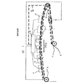
図1に基づき、印刷中断時における上記の問題をさらに説明する。ここでは被印刷物として被印刷物レーン3を使用するが、これによって本発明は被印刷物レーンに制限されるものではない。さらにこの実施例では、上記の印刷ユニットが複数の印刷ヘッドを有することを前提とする。しかしながらこれらの実施例は、印刷ユニットがただ1つの印刷ヘッドしか有しない場合にも有効である。 Based on FIG. 1, the above problem at the time of interruption of printing will be further described. Here, the substrate lane 3 is used as the substrate to be printed. However, the present invention is not limited to the substrate lane. Furthermore, in this embodiment, it is assumed that the printing unit has a plurality of print heads. However, these embodiments are also effective when the printing unit has only one print head.
ここに示されているのは、印刷装置DRの1つの印刷ユニット1および1つの印刷機制御部2である。被印刷物レーン3に沿って印刷ユニット1が配置されており、この印刷ユニットは、被印刷物レーン3の搬送方向PFOで見て相前後して、複数の印刷ヘッド5を備えた印刷バー(Druckriegel)4を有する。カラー印刷の場合、例えば印刷色当たり1つずつの印刷バー4を設けることができる。被印刷物レーン3は、排出ローラ9により、印刷バー4の横を通り過ぎて移動する。被印刷物レーンは、ガイドローラ8を有するサドルの上に載置している。印刷ユニット1の入口部にはセンサが配置されており、このセンサは、被印刷物レーン3の押し出し運動に依存して印刷クロックパルスTDを形成し、この印刷クロックパルスは、印刷機制御部2に供給され、また例えば、印刷のための印刷データがすでに印刷機制御部2に存在する場合に個々の印刷ヘッド5のノズルにおけるインク滴の吐出時点を決定するため、印刷機制御部2によって使用される。このセンサは、例えば、被印刷物レーン3によって駆動制御される回転センサローラまたはエンコーダローラ6として構成することができる。
Shown here is one
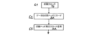
図2によれば、被印刷物レーン3の押し出しに同期してエンコーダローラ6によって印刷クロックパルスTD(ステップS1)が形成される。すなわち、例えば、印刷すべき記号のピクセル毎に1つの印刷クロックパルスTDがエンコーダローラ6から印刷機制御部2に出力されるのである。印刷機制御部は、各印刷クロックパルスTDの後、各印刷ヘッド5に印刷データDAを供給し(図2のステップS2)、つぎに印刷スタート信号SAによって、インク滴の送出を印刷スタート信号SAによってトリガする(図2のステップS3)。印刷ヘッド5は、公知のようにインクチャネルを備えたノズルを有しており、これらのノズルは、例えば、DoD原理にしたがい、圧電アクチベータによってインク滴を形成することができ、これらのインク滴は、被印刷物レーン3に向けられて、そこに印刷点を形成する。被印刷物レーン3は、エンコーダローラ6の前に配置されている駆動ローラ7によってエンコーダローラ6に供給される。
According to FIG. 2, a printing clock pulse T D (step S <b> 1) is formed by the encoder roller 6 in synchronization with the extrusion of the substrate lane 3. That is, for example, one print clock pulse T D for each pixel of the symbol to be printed is being outputted from the encoder roller 6 to the printing
印刷動作が中断される場合、減速フェーズおよび加速フェーズ中には冒頭に説明した問題が発生する。 When the printing operation is interrupted, the problems described at the beginning occur during the deceleration phase and the acceleration phase.
上記の2つのケースにおいて、上記のフェーズ中に被印刷物レーン3が運動し、その結果、エンコーダローラ6は印刷クロックパルスTDを出力する。つぎに印刷データDAのある印刷ヘッド5に印刷スタート信号SAが供給されて、これらの印刷ヘッドは、後続の印刷において被印刷物レーン3にインク滴を吐出する。しかしながら被印刷物レーン3の減速フェーズにおいて印刷クロックパルスTD間の時間間隔は、印刷動作に比べて長くなり続けるため、ノズル開口部におけるインクの粘度は次第に変化して、圧電アクチベータによってインク滴を問題なく形成することはできなくなるおそれがある。これに相応して、上記の加速フェーズ中に印刷クロックパルスTDの時間間隔は短くなるため、印刷中断後の加速の開始時には、印刷ヘッドからのインク滴の吐出が妨げられるほどインクの粘度が変化している可能性がある。
In the above two cases, the substrate lane 3 in the above phase to movement, so that the encoder roller 6 outputs a print clock pulse T D. Next, a print start signal SA is supplied to the
図3により、印刷中断時における被印刷物レーン3の速度Gの経過が、時間tについて示されている。被印刷物レーン3は、印刷中断をトリガするまで、印刷速度GDで搬送される(部分A1)。引き続いて被印刷物レーン3は制動され、減速ランプRVにおいてほぼ停止状態にさせられる(部分A2)。印刷中断(部分A3)の後、被印刷物レーン3は、加速ランプRBにおいて停止状態から再び印刷速度GDに加速される(部分A4)。 FIG. 3 shows the passage of the speed G of the substrate lane 3 when printing is interrupted for the time t. The substrate Lane 3, until triggers the printing interruption, is transported at a printing speed G D (portion A1). Is the substrate Lane 3 subsequently being braked, it is substantially is stopped in the deceleration ramp R V (portion A2). After the printing interruption (part A3), the substrate Lane 3 is accelerated to printing speed G D again from a stopped state in the acceleration ramp R B (portion A4).
図4aには、印刷速度GDにおける印刷クロックパルスTDの列が時間tについてプロットされている(図3の部分A1)。各印刷クロックパルスTDにおいて、印刷データDAが存在する場合には、印刷ヘッド5のノズルから被印刷物レーン3に向かってインク滴を吐出することができる。図4bには、減速ランプRV(図3の部分A2)中の印刷クロックパルスTDの列が示されている。印刷クロックパルスTDの時間間隔は長くなる。図4cからわかるのは、印刷クロックパルスTD間に(破線で示した)振動パルスVをどのように形成でき、これらを印刷ヘッド5に供給できるかがである。振動パルスVにより、印刷ヘッド5において公知のように、あらかじめ設定した数の振動振幅を有する振動サイクルをトリガすることができる。印刷中断の前後の印刷クロックパルスの時間間隔TDがそれを許容する場合(例えば図5a)、印刷クロックパルスTD間に複数の振動サイクル、例えば2つまたは3つの振動サイクルをトリガすることも可能である(図5b)。
The Figure 4a, rows of printing clock pulse T D in printing speed G D are plotted with respect to time t (the portion of FIG. 3 A1). In each print clock pulse T D, when the print data DA are present, it is possible to eject ink droplets toward the nozzle of the
図4には減速ランプRV中の状況と、加速ランプRB中の状況とが示されており、両者は互いに逆になっている。ここでは印刷クロックパルスTD間の時間間隔は、被印刷物レーン3の速度Gに依存して短くなり続けている。 The situation during deceleration ramp R V in FIG. 4, there is shown the situation during acceleration ramp R B is, both are reversed to each other. Wherein the time interval between the print clock pulse T D is continues shorter depending on the speed G of the substrate lane 3.
1つの振動サイクルにおいて複数の振動振幅が生じるため、時間間隔が許容すれば、印刷クロックパルスTD間に1つの振動サイクルだけを実行することができる。これが可能である否かは、印刷速度GDに依存する。したがって、例えば印刷速度GDが高い際には、被印刷物レーン3の速度が部分的にすでに低減されておりかつ印刷クロックパルスの時間間隔TDがあらかじめ設定した値に達している値に達している場合に、例えば、被印刷物レーン3の速度が、印刷速度GDの半分まで下がっているか、または被印刷物レーン3が、例えば、加速ランプRBにおける印刷速度GDの半分にまだ達していない(図3のレベルE、フェーズPH)場合にはじめて、上記の振動サイクルのトリガが意味を持ち得るのである。 Since a plurality of vibration amplitude in one oscillation cycle occurs, if the allowable time interval, it is possible only to run one oscillation cycle between the print clock pulse T D. Whether this is possible will depend on the printing speed G D. Thus, for example, when high print speed G D is reached a value has reached a value that the speed of the substrate lane 3 is the time interval T D of partially already reduced and and print clock pulses preset If you are, for example, the speed of the substrate lane 3, or has dropped to half of the printing speed G D, or the substrate lane 3, for example, have not yet reached half the print speed G D in acceleration ramp R B Only in the case of (level E, phase PH in FIG. 3) can the trigger of the oscillation cycle be meaningful.
両ランプRにおいて被印刷物レーン3が減速または加速される場合、エンコーダローラ6は、印刷クロックパルスTDを形成し続けるため、印刷ヘッド5は、印刷データDAが存在する場合には印刷し続ける。図4bには、制動フェーズRB中の印刷クロックパルスTDの列が原理的に示されている。個々の印刷クロックパルスTD間の時間間隔は、図4aの印刷動作に比べて長くなっているため、ノズル開口部における粘度の変化に起因してインク滴の吐出が不十分になるという上述した危険性がある。この問題を回避するため、本発明では印刷クロックパルスTD間で、1つの振動パルスVにより、少なくとも1つの振動サイクルをトリガする。すなわち、各インクチャネルのアクチベータが、ノズルの端部に振動を形成して、これにより、この端部において、つぎの印刷スタート信号SAがトリガされる前にインクが殊にノズル開口部で混合されるようにするのである。エンコーダローラ6が印刷クロックパルスTDを形成する場合にはつねに、印刷の準備が整った印刷ヘッド5のアクチベータに、またはすべての印刷ヘッド5に、少なくとも1つの振動パルスVを供給することができ、これに起因して、複数の振動からなる少なくとも1つの振動サイクルを複数のノズルにおいて形成してインクを混合することできる。
If the substrate lane 3 is decelerated or accelerated in both lamps R, the encoder roller 6, to continue to form the print clock pulse T D, the
DR 印刷装置、 1 印刷ユニット、 2 印刷機制御部、 3 被印刷物レーン、 4 印刷バー、 5 印刷ヘッド、 6 センサ−エンコーダローラ、 7 駆動ローラ、 8 ガイドサドル、 9 排出ローラ、 TD 印刷クロックパルス、 V 振動パルス、 G 被印刷物レーンの速度、 GD 印刷速度、 PH 振動フェーズ、 A 部分、 R ランプ、 RV 減速ランプ、 RB 加速ランプ、 E レベル、 t 時間 DR printing apparatus, first printing unit, 2 printing press control unit, 3 the substrate lanes 4 print bars, 5 print head, 6 sensor - encoder roller, 7 a drive roller 8 guides the saddle, 9 discharge roller, T D printing clock pulse , V shaking pulses, the speed of G the substrate lane, G D printing speed, PH oscillation phase, a part, R lamp, R V deceleration ramp, R B acceleration ramp, E levels, t time
Claims (3)
当該方法では、少なくとも1つの印刷ヘッド(5)を有する印刷ユニット(1)によって被印刷物(3)が印刷され、
前記印刷中断のトリガに伴い、減速ランプ(RV)において印刷動作時の速度(GD)から、あらかじめ設定した速度に前記被印刷物(3)の押し出し速度が低減され、前記印刷中断の後、加速ランプ(RB)において再び印刷速度(GD)に加速され、
センサ(6)を用いて前記被印刷物(3)の押し出しに依存して印刷クロックパルス(TD)が形成されて、当該印刷クロックパルスが前記印刷機制御部(2)に供給され、
前記方法では、前記両ランプ(R)中、
前記印刷クロックパルス(TD)の相互の時間間隔があらかじめ設定した値に達した場合、前記印刷機制御部(2)によって少なくとも1つの印刷ヘッド(5)に少なくとも1つの振動パルス(V)を送信して、当該印刷ヘッド(5)において複数の振動振幅からなる少なくとも1つのサイクルが実施されるようにする、
ことを特徴とする方法。 In a method for performing a print interruption in a printing operation of an ink printing system having at least one printing device (DR),
In the method, the substrate (3) is printed by a printing unit (1) having at least one print head (5),
With the printing interruption trigger, the extrusion speed of the substrate (3) is reduced from the speed (G D ) at the time of the printing operation in the deceleration ramp (R V ) to a preset speed, and after the printing interruption, The acceleration ramp (R B ) accelerates again to the printing speed (G D ),
A printing clock pulse (T D ) is formed using the sensor (6) depending on the extrusion of the substrate (3), and the printing clock pulse is supplied to the printing press controller (2).
In the method, in both lamps (R),
When the mutual time interval of the print clock pulses (T D ) reaches a preset value, at least one vibration pulse (V) is applied to at least one print head (5) by the printing press controller (2). Transmitting so that at least one cycle of a plurality of vibration amplitudes is carried out in the print head (5),
A method characterized by that.
前記被印刷物(3)の前記押し出し速度が前記印刷速度の半分よりも小さい場合に、はじめて第1の振動パルス(V)を形成する、
ことを特徴とする方法。 The method of claim 1, wherein
The first vibration pulse (V) is formed only when the extrusion speed of the substrate (3) is smaller than half of the printing speed.
A method characterized by that.
前記印刷ユニット(1)は複数の印刷ヘッド(5)を有しており、
前記両ランプ(R)中、
印刷クロックパルス(TD)の発生時に、前記印刷機制御部(2)内に印刷データ(DA)が存在する複数の印刷ヘッド(5)に印刷スタート信号(SA)を供給し、
当該スタート信号(SA)に基づき、駆動制御される前記印刷ヘッド(5)によってインク滴を吐出し、
その際に印刷クロックパルス(TD)の後、つぎの印刷クロックパルス(TD)が前記センサ(6)によって形成される前に少なくとも1つの振動パルス(V)を前記印刷ヘッド(5)に送信する、
ことを特徴とする方法。 The method of claim 2, wherein
The printing unit (1) has a plurality of print heads (5),
In both the lamps (R),
When a print clock pulse (T D ) is generated, a print start signal (SA) is supplied to a plurality of print heads (5) in which print data (DA) exists in the printing press controller (2),
Based on the start signal (SA), ink droplets are ejected by the print head (5) that is driven and controlled.
After printing the clock pulse (T D) At that time, at least one of said print head vibrating pulse (V) (5) before the next print clock pulse (T D) is formed by the sensor (6) Send,
A method characterized by that.
Applications Claiming Priority (2)
| Application Number | Priority Date | Filing Date | Title |
|---|---|---|---|
| DE102012107776.2 | 2012-08-23 | ||
| DE102012107776.2A DE102012107776B4 (en) | 2012-08-23 | 2012-08-23 | Method for performing a printing interruption in the printing operation of an ink printing system with at least one printing device |
Publications (2)
| Publication Number | Publication Date |
|---|---|
| JP2014040099A true JP2014040099A (en) | 2014-03-06 |
| JP2014040099A5 JP2014040099A5 (en) | 2016-06-23 |
Family
ID=50069502
Family Applications (1)
| Application Number | Title | Priority Date | Filing Date |
|---|---|---|---|
| JP2013173343A Pending JP2014040099A (en) | 2012-08-23 | 2013-08-23 | Method for interrupting printing in printing operation of an inkjet printing system comprising at least one printer, and printer |
Country Status (3)
| Country | Link |
|---|---|
| US (1) | US8870324B2 (en) |
| JP (1) | JP2014040099A (en) |
| DE (1) | DE102012107776B4 (en) |
Families Citing this family (2)
| Publication number | Priority date | Publication date | Assignee | Title |
|---|---|---|---|---|
| DE102014101428A1 (en) * | 2014-02-05 | 2015-08-06 | Océ Printing Systems GmbH & Co. KG | Method for controlling the printing elements of an inkjet print head of an inkjet printing device |
| JP7562462B2 (en) * | 2021-03-24 | 2024-10-07 | 株式会社Screenホールディングス | Printing device and printing system |
Citations (3)
| Publication number | Priority date | Publication date | Assignee | Title |
|---|---|---|---|---|
| JP2005104107A (en) * | 2003-10-02 | 2005-04-21 | Seiko Epson Corp | Liquid ejection device and method of controlling microvibration thereof |
| JP2010274637A (en) * | 2009-06-01 | 2010-12-09 | Ricoh Co Ltd | Method for controlling ink drop ejection, and inkjet recorder |
| JP2012148564A (en) * | 2011-01-17 | 2012-08-09 | Oce Printing Systems Gmbh | Method for performing function of pause during printing operation in ink type printing device |
Family Cites Families (4)
| Publication number | Priority date | Publication date | Assignee | Title |
|---|---|---|---|---|
| DE69736991T2 (en) | 1996-01-29 | 2007-07-12 | Seiko Epson Corp. | Ink jet recording head |
| JP4204508B2 (en) * | 2004-04-27 | 2009-01-07 | 株式会社リコー | Image forming apparatus |
| EP1795356A1 (en) * | 2005-12-01 | 2007-06-13 | Agfa Graphics N.V. | A method for increasing the reliability of an inkjet printing system |
| JP2009154328A (en) * | 2007-12-25 | 2009-07-16 | Fuji Xerox Co Ltd | Liquid droplet discharge head and image forming apparatus equipped with the same |
-
2012
- 2012-08-23 DE DE102012107776.2A patent/DE102012107776B4/en active Active
-
2013
- 2013-08-22 US US13/973,380 patent/US8870324B2/en active Active
- 2013-08-23 JP JP2013173343A patent/JP2014040099A/en active Pending
Patent Citations (3)
| Publication number | Priority date | Publication date | Assignee | Title |
|---|---|---|---|---|
| JP2005104107A (en) * | 2003-10-02 | 2005-04-21 | Seiko Epson Corp | Liquid ejection device and method of controlling microvibration thereof |
| JP2010274637A (en) * | 2009-06-01 | 2010-12-09 | Ricoh Co Ltd | Method for controlling ink drop ejection, and inkjet recorder |
| JP2012148564A (en) * | 2011-01-17 | 2012-08-09 | Oce Printing Systems Gmbh | Method for performing function of pause during printing operation in ink type printing device |
Also Published As
| Publication number | Publication date |
|---|---|
| US20140055515A1 (en) | 2014-02-27 |
| US8870324B2 (en) | 2014-10-28 |
| DE102012107776A1 (en) | 2014-02-27 |
| DE102012107776B4 (en) | 2016-05-25 |
Similar Documents
| Publication | Publication Date | Title |
|---|---|---|
| JP6296753B2 (en) | Method for performing a print interruption during a printing operation of an ink printing system having at least one printing press | |
| JP6645749B2 (en) | Method for controlling oscillating and refreshing operations during a printing operation of an ink-based printing system having at least one printing device | |
| JP5347725B2 (en) | Ink droplet ejection control method and ink jet recording apparatus | |
| US9308720B2 (en) | Ink jet printer and printing method | |
| US9205645B2 (en) | Method to control the printing elements of an ink print head of an ink printing apparatus | |
| JP2014083851A5 (en) | ||
| CN106183479B (en) | The control method of inkjet-printing device | |
| JP2007253337A (en) | Inkjet printer and method for printing therein | |
| JP6264286B2 (en) | Head drive unit and inkjet printer | |
| JP6124736B2 (en) | Method for performing a print interruption during a printing operation of an ink printing system having at least one printing press | |
| JP6598602B2 (en) | Method for driving an actuator for a first nozzle of a plurality of nozzles of an inkjet printing system | |
| JP2014040099A (en) | Method for interrupting printing in printing operation of an inkjet printing system comprising at least one printer, and printer | |
| JP4862552B2 (en) | Droplet ejection device, droplet ejection control device, and droplet ejection method | |
| JP2013014130A (en) | Precursor control device and control method of inkjet head | |
| JP2001113728A (en) | Ink-jet printer and its method for preparatory driving | |
| JP2009006685A (en) | Fluid ejector and fluid ejection method | |
| JP2021084392A (en) | Liquid discharge device, and discharge control method of the liquid discharge device | |
| JP2014040099A5 (en) | ||
| JP5449698B2 (en) | Ink jet printer and all nozzle discharge control method for ink jet printer | |
| JP2018020566A (en) | Method for stabilizing ink meniscus in ink-jet printing system and control unit | |
| JP5712619B2 (en) | Liquid ejection apparatus and liquid ejection method | |
| JP2012158001A (en) | Device and method for ejecting liquid | |
| JP2011136528A (en) | Image recorder and image recording method | |
| JP2013035142A (en) | Image data transfer device and inkjet recording apparatus | |
| JP2004142333A (en) | Inkjet recording device |
Legal Events
| Date | Code | Title | Description |
|---|---|---|---|
| A072 | Dismissal of procedure [no reply to invitation to correct request for examination] |
Free format text: JAPANESE INTERMEDIATE CODE: A072 Effective date: 20140324 |
|
| A521 | Request for written amendment filed |
Free format text: JAPANESE INTERMEDIATE CODE: A523 Effective date: 20160426 |
|
| A621 | Written request for application examination |
Free format text: JAPANESE INTERMEDIATE CODE: A621 Effective date: 20160426 |
|
| A131 | Notification of reasons for refusal |
Free format text: JAPANESE INTERMEDIATE CODE: A131 Effective date: 20170327 |
|
| A02 | Decision of refusal |
Free format text: JAPANESE INTERMEDIATE CODE: A02 Effective date: 20171204 |