JP2014019347A - Lamp control device of vehicle - Google Patents
Lamp control device of vehicle Download PDFInfo
- Publication number
- JP2014019347A JP2014019347A JP2012161068A JP2012161068A JP2014019347A JP 2014019347 A JP2014019347 A JP 2014019347A JP 2012161068 A JP2012161068 A JP 2012161068A JP 2012161068 A JP2012161068 A JP 2012161068A JP 2014019347 A JP2014019347 A JP 2014019347A
- Authority
- JP
- Japan
- Prior art keywords
- control
- lamp
- line
- control signal
- lamp control
- Prior art date
- Legal status (The legal status is an assumption and is not a legal conclusion. Google has not performed a legal analysis and makes no representation as to the accuracy of the status listed.)
- Pending
Links
Images


Landscapes
- Lighting Device Outwards From Vehicle And Optical Signal (AREA)
Abstract
Description
本発明は自動車等の車両に配設される複数のランプの点灯・消灯や配光等の各種制御を行うためのランプ制御装置に関し、特に障害発生時のフェイルセイフを可能にしたランプ制御装置に関するものである。 The present invention relates to a lamp control device for performing various controls such as lighting / extinguishing of a plurality of lamps arranged in a vehicle such as an automobile, and a light distribution, and more particularly to a lamp control device that enables fail-safe when a failure occurs. Is.
近年の車両、特に自動車では、ヘッドランプの点消灯、配光、ランプ照射方向等の各種ランプ制御を行うために専用の電子回路ユニット(以下、ランプECUと称する)が設けられている。このランプECUは車両の走行に伴って車両に設けたスイッチや各センサから順次出力されてくるスイッチ信号や、車速や操舵角等の各種検出信号に基づいてランプ制御を実行し、当該走行の状況に適した点灯状態に制御することが可能とされている。このランプECUは個々のランプにそれぞれ対応して設けられるが、例えば左右のヘッドランプに設けた各ランプECUがそれぞれ独立して動作すると、左右のヘッドランプのランプ制御に食い違いが生じることがあり好ましくない。そのため、特許文献1では自動車の左右に設けられたヘッドランプの一方に配設したランプECUをマスターECUとして構成し、他方のヘッドランプに配設したランプECUをスレーブECUとして構成し、マスターECUにおいて主となる処理を行って得られた制御信号に基づいて自身側の一方のランプを制御すると同時に、当該得られた制御信号をスレーブECUに伝送し、この伝送した制御信号に基づいてスレーブECUにより他方のランプを制御する技術が提案されている。このように一方のヘッドランプに設けたマスターECUからスレーブECUに制御信号を伝送することで、同じ制御信号に基づいて左右のヘッドランプを一体的にランプ制御することが可能になる。
In recent vehicles, particularly automobiles, dedicated electronic circuit units (hereinafter referred to as lamp ECUs) are provided to perform various lamp controls such as turning on / off the headlamp, light distribution, and lamp irradiation direction. This lamp ECU executes lamp control based on switch signals sequentially output from the switches and sensors provided on the vehicle as the vehicle travels, and various detection signals such as vehicle speed and steering angle, and It is possible to control the lighting state suitable for the above. The lamp ECUs are provided corresponding to the individual lamps. For example, if the lamp ECUs provided on the left and right headlamps operate independently, there may be a difference in lamp control between the left and right headlamps. Absent. Therefore, in
この特許文献1のようなマスター・スレーブ方式を採用したランプ制御装置では、マスターとスレーブの各ランプECU間での制御信号の伝送をLIN(Local Interconnect Network)通信で行っており、そのために両ランプECUをLINラインとして構成された制御ライン(ハーネス)で接続している。そして、複数のランプ制御、例えばヘッドランプの点消灯を制御する点灯状態制御、ロービームやハイビーム等の配光を制御する配光制御、ランプ光軸を水平左右方向に偏向制御するスイブル制御、ランプ光軸を鉛直上下方向に偏向制御するレベリング制御等を行うランプ制御装置では、これら各制御信号を伝送するために両ランプECUを2本の制御ラインで接続し、1本をスイブル制御専用の制御ラインとし、他の1本を点灯状態制御およびレベリング制御の制御用の制御ラインとして構成している。これは、スイブル制御は車両の走行に伴って頻繁に行われて当該スイブル制御信号の時間当たりの伝送容量が大きいため、1本の制御ラインを伝送容量の大きなスイブル制御用に専用化するためである。その一方で点灯制御、配光制御、レベリング制御は制御の頻度が少なくてこれらの制御信号の時間当たりの伝送容量が小さいため、他の1本の制御ラインで点灯制御、配光制御、レベリング制御を行うようにしている。
In the lamp control apparatus adopting the master / slave system as in
しかし、このようにランプ制御のための複数の制御信号を2本の制御ラインに割り当てると、制御ラインが断線、地絡する等の障害が生じたときにランプ制御のフェイルセイフが確保されなくなるという問題が生じる。スイブル制御用の制御ラインに障害が生じたときにはスイブル制御が行われなくなるが、そのときにはランプ光軸を所定位置に固定してしまえば以降において特に問題になることは少ない。一方、他の制御ラインに障害が生じたときには、レベリング制御についてはスイブル制御と同様に所定位置に固定してしまえば特に問題になることは少ないが、点灯制御や配光制御、特に点灯制御が行われなくなると、ランプを点灯することができなくなる状況が生じ、安全走行の点で極めて重要な問題が生じることになる。 However, if a plurality of control signals for lamp control are assigned to the two control lines in this way, failure of the lamp control will not be ensured when a failure such as disconnection or ground fault occurs in the control line. Problems arise. When a trouble occurs in the control line for swivel control, swivel control is not performed. At that time, if the lamp optical axis is fixed at a predetermined position, there is little problem in the future. On the other hand, when a failure occurs in another control line, leveling control is not particularly problematic if it is fixed at a predetermined position as in swivel control, but lighting control and light distribution control, especially lighting control, are not. If this is not done, there will be a situation where the lamp cannot be turned on, which will cause a very important problem in terms of safe driving.
本発明の目的は複数のランプECUを接続する制御ラインに障害が生じた場合でも安全走行に必要とされるランプ制御用の制御信号の伝送を可能にしてフェイルセイフを確保することが可能な車両のランプ制御装置を提供するものである。 An object of the present invention is a vehicle capable of ensuring a fail-safe by enabling transmission of a control signal for lamp control required for safe driving even when a failure occurs in a control line connecting a plurality of lamp ECUs. The lamp control device is provided.
本発明は、少なくとも2つのランプと、各ランプにそれぞれ設けられたランプ制御手段とを備え、これらランプ制御手段を複数本の制御ラインで接続して当該制御ラインを介して1つのランプ制御手段から他のランプ制御手段にランプ制御信号を伝送する車両用ランプ制御装置であって、制御ラインを監視するとともに、重要度の高いランプ制御信号が割り当てられている制御ラインに異常が生じたときに、当該重要度の高いランプ制御信号を正常な制御ラインに切り替えて割り当てるライン監視・設定手段を備えることを特徴とする。このライン監視・設定手段は、異常が生じた制御ラインに割り当てられていた重要度の低いランプ制御を停止又は抑制する構成となる。 The present invention comprises at least two lamps and lamp control means provided for each lamp, and these lamp control means are connected by a plurality of control lines, and one lamp control means is connected via the control lines. A vehicle lamp control device that transmits a lamp control signal to another lamp control means, and monitors a control line, and when an abnormality occurs in a control line to which a lamp control signal having a high importance is assigned, It is characterized by comprising line monitoring / setting means for switching and assigning the lamp control signal having high importance to a normal control line. This line monitoring / setting unit is configured to stop or suppress lamp control with low importance assigned to a control line in which an abnormality has occurred.
本発明は、具体的には、車両に配設された2つのヘッドランプと、一方のヘッドランプに設けられたマスターランプ制御手段と、他方のヘッドランプに設けられたスレーブランプ制御手段を備え、これらのランプ制御手段を第1および第2の制御ラインで接続し、当該制御ラインを介してマスターランプ制御手段からスレーブランプ制御手段にランプ制御信号を伝送する車両用ランプ制御装置であって、第1と第2の制御ラインを監視するとともに、ヘッドランプの点灯・消灯を制御するための点灯制御信号が割り当てられている第1制御ラインに異常が生じたときに、当該点灯制御信号を正常な第2制御ラインに切り替えて割り当てるライン監視・設定手段を備えることを特徴とする。 Specifically, the present invention includes two headlamps disposed in a vehicle, master lamp control means provided in one headlamp, and slave lamp control means provided in the other headlamp, A vehicle lamp control device that connects these lamp control means via a first and second control line and transmits a lamp control signal from the master lamp control means to the slave lamp control means via the control line. 1 and the second control line are monitored, and when an abnormality occurs in the first control line to which the lighting control signal for controlling lighting / extinguishing of the headlamp is abnormal, the lighting control signal is set to normal. Line monitoring / setting means for switching and assigning to the second control line is provided.
ライン監視・設定手段は、第2制御ラインにランプ光軸を左右に偏向制御するためのスイブル制御信号を割り当てており、点灯制御信号を当該第2制御ラインに割り当てたときに、スイブル制御信号の伝送を停止し、またはその伝送容量を低減させる構成とする。さらに、ライン監視・設定手段は、第1制御ラインに点灯制御信号の他に配光制御信号とレベリング制御信号の少なくとも一つを割り当てる構成とする。 The line monitoring / setting means assigns a swivel control signal for deflection control of the lamp optical axis to the left and right to the second control line, and when the lighting control signal is assigned to the second control line, the swivel control signal The transmission is stopped or the transmission capacity is reduced. Furthermore, the line monitoring / setting unit is configured to assign at least one of a light distribution control signal and a leveling control signal to the first control line in addition to the lighting control signal.
本発明によれば、車両の安全走行における重要度の高いランプ制御が割り当てられている制御ラインが異常と判定されたときには、他の正常な制御ラインに割り当てられているランプ制御を停止または抑制し、当該正常な制御ラインに当該重要度の高いランプ制御を割り当てる。これにより、正常な制御ラインを用いて1つのランプ制御手段から他のランプ制御手段に重要度の高いランプ制御の制御信号を伝送することが確保でき、フェイルセイフを確保したランプ制御が実現できる。 According to the present invention, when it is determined that the control line to which the lamp control with high importance in the safe driving of the vehicle is assigned is abnormal, the lamp control assigned to another normal control line is stopped or suppressed. The lamp control having a high importance is assigned to the normal control line. Accordingly, it is possible to ensure that a lamp control control signal having a high degree of importance is transmitted from one lamp control means to another lamp control means using a normal control line, and it is possible to realize lamp control that ensures fail-safety.
すなわち、本発明を車両に配設された2つのヘッドランプに適用した場合には、一方のヘッドランプに設けられたマスターランプ制御手段と、他方のヘッドランプに設けられたスレーブランプ制御手段を第1および第2の制御ラインで接続し、第1と第2の制御ラインを監視するとともに、ランプ制御に際して重要度の高いヘッドランプの点灯・消灯を制御するための点灯制御信号が割り当てられている第1制御ラインに異常が生じたときに、当該点灯制御信号を正常な第2制御ラインに切り替えて割り当てるので、最低でも2つのヘッドランプの点灯状態を保持するという点灯制御を確保することができ、フェイルセイフを確保したランプ制御が実現できる。 That is, when the present invention is applied to two headlamps provided in a vehicle, the master lamp control means provided in one headlamp and the slave lamp control means provided in the other headlamp The first and second control lines are connected, the first and second control lines are monitored, and a lighting control signal for controlling lighting / extinguishing of the head lamp having high importance in lamp control is assigned. When an abnormality occurs in the first control line, the lighting control signal is switched and assigned to the normal second control line, so that it is possible to ensure lighting control that maintains at least two headlamp lighting states. In addition, lamp control with fail-safe can be realized.
次に、本発明の実施の形態について図面を参照して説明する。図1は本発明を自動車の左右のヘッドランプLHL,RHLについて、その点消灯を行う点灯制御と、ランプの配光をハイビーム配光とロービーム配光に切替えて制御する配光制御と、ランプ光軸を水平左右に偏向制御するスイブル制御と、ランプ光軸を鉛直上下方向に偏向制御するレベリング制御を行うランプ制御装置に適用した実施形態の概念構成図である。図1には表れない自動車の前部の左右に右ヘッドランプRHLと左ヘッドランプLHLが配設されており、左ヘッドランプLHLには左ランプECU100が配設され、右ヘッドランプRHLには右ランプECU200が配設されている。これら左右の各ランプECU100,200は後述するように各ヘッドランプLHL,RHLに設けたランプユニットの光源、可変シェード、スイブル機構、レベリング機構をそれぞれ制御することが可能とされている。そして、この実施形態では、一方のヘッドランプ、ここでは左ランプLHLに設けた左ランプECU100はマスターECUとして構成されており、他方の右ヘッドランプRHLに設けた右ランプECU200はスレーブECUとして構成されている。
Next, embodiments of the present invention will be described with reference to the drawings. FIG. 1 shows a lighting control for turning on and off the left and right headlamps LHL and RHL of an automobile, a light distribution control for controlling a lamp light distribution by switching between a high beam light distribution and a low beam light distribution, and lamp light. It is a conceptual block diagram of an embodiment applied to a lamp control device that performs swivel control for deflecting the axis horizontally and horizontally and leveling control for deflecting the lamp optical axis vertically. A right headlamp RHL and a left headlamp LHL are disposed on the left and right of the front portion of the automobile that do not appear in FIG. 1, a
前記マスターECU100は、内蔵されているCAN(Controller Area Network)インターフェース107を介してCANラインL0に接続されている。このCANラインL0は、自動車に設けた各種スイッチSWや各種センサSS、さらには図1には表れないが自動車の総合的な制御を行う車両ECUが接続されている。また、マスターECU100とスレーブECU200はそれぞれに設けたLINインターフェース106,206を介して第1および第2の制御ラインL1,L2によって相互に接続されている。これら第1と第2の制御ラインL1,L2はLINラインとして構成されており、マスターECU100とスレーブECU200の間で制御信号を伝送することが可能とされている。
The master ECU 100 is connected to a CAN line L0 via a built-in CAN (Controller Area Network)
前記CANラインL0に接続されている各種スイッチSWについての説明は省略するが、例えばイグニッションスイッチ、ヘッドランプを点灯・消灯するためのランプ点灯スイッチ、ヘッドランプの配光をロービーム配光とハイビーム配光に切り替えるためのディマースイッチが設けられる。また、各種センサSSについての説明も省略するが、例えば撮像カメラCAMで撮像した映像に基づいて他車等を検出する他車両検出センサ、自車両の車速を検出する車速センサ、自車両の操舵方向を検出する操舵角センサ、自車両の前後の車高を検出して自車両の傾き角、すなわちピッチ角を検出するための車高センサが設けられる。これら各種スイッチSWの切替信号や、各種センサSSの検出信号はそれぞれCANラインL0を通して図示を省略した車両ECUに入力され、ここで所定の処理が行われて第1次のランプ制御信号が生成され、この生成された第1次のランプ積信号は前記CANラインL0を通して前記マスターECU100に入力される。
The description of the various switches SW connected to the CAN line L0 is omitted. For example, an ignition switch, a lamp lighting switch for turning on / off the headlamp, and the light distribution of the headlamp are low beam distribution and high beam distribution. A dimmer switch for switching to is provided. Although explanation about various sensors SS is also omitted, for example, another vehicle detection sensor for detecting another vehicle or the like based on an image captured by the imaging camera CAM, a vehicle speed sensor for detecting the vehicle speed of the host vehicle, and the steering direction of the host vehicle. And a vehicle height sensor for detecting the vehicle height before and after the host vehicle and detecting the tilt angle of the host vehicle, that is, the pitch angle. These switching signals of the various switches SW and detection signals of the various sensors SS are respectively input to the vehicle ECU (not shown) through the CAN line L0, where predetermined processing is performed to generate a primary lamp control signal. The generated first ramp product signal is input to the
前記左右のヘッドランプLHL,RHLは左右が対称であることを除けば同じ構成である。図2は左ヘッドランプLHLの概略構成を示す縦断面図であり、前面を開口した容器状のランプボディ11と、このランプボディ11の前面開口に取着される透光性の前面カバー12とでランプハウジング1が構成されており、このランプハウジング1内にプロジェクタ型のランプユニット2が内装されている。このランプユニット2はランプベース21上に光源としてのLED22が搭載されるとともに、このLED22を覆うように回転楕円面の一部で構成されたリフレクタ23が配設されている。また、ランプベース21の前端部には照射レンズ24が支持されるとともに、この照射レンズ24と前記リフレクタ23との間に可変シェード3が配設されている。
The left and right headlamps LHL and RHL have the same configuration except that the left and right headlamps are symmetrical. FIG. 2 is a longitudinal sectional view showing a schematic configuration of the left head lamp LHL. A container-shaped
このランプユニット2では、LED22が発光したときに出射された光をリフレクタ23により前方に向けて反射し、当該リフレクタ23で反射された反射光ないしLED22から直接出射された光を照射レンズ24によりランプユニット2の前方に向けて照射する。また、可変シェード3を制御することによりLED22から出射した光の一部を遮光し、あるいは遮光することなく照射レンズ24に入射する光束を制御し、ハイビーム配光とロービーム配光を切り替えることができる。前記可変シェード3は支点31を中心にして上下方向に傾動されるシェード体32と、このシェード体32を駆動するソレノイドアクチュエータ等のシェードアクチュエータ33で構成されており、シェードアクチュエータ33によってシェード体32はLED22から出射される光の光路に対して進退され、進出したときに遮光を行ってロービーム配光とし、後退したときに遮光することなくハイビーム配光とする。
In the
前記ランプユニット2はランプハウジング1内において支点61においてランプ前後方向に傾動可能に軸支された傾動フレーム6に搭載されている。この傾動フレーム6の一部にはレベリング機構4が連結されており、このレベリング機構4が駆動されたときに傾動フレーム6をランプ前後方向に傾動してランプユニット2のランプ光軸Lxを上下方向に偏向制御することが可能とされている。レベリング機構4は、ここでは軸転するスクリューロッド42を有してランプボディ11に固定支持されたモータ41を有しており、スクリューロッド42に螺合されたナット43を前記傾動フレーム6に取着することで、スクリューロッド42の軸転に伴ってナット43を螺進させ、これと共に傾動フレーム6を傾動させる公知の構成を採用している。
The
また、前記ランプユニット2は水平方向に回動するスイブル機構5に連結されており、このスイブル機構5が駆動されたときにランプユニット2のランプ光軸Lxを左右方向に偏向制御することが可能とされている。スイブル機構5は前記傾動フレーム6の下面部に支持されたスイブル駆動ユニット51を有しており、このスイブル駆動ユニット51の回転出力軸52を前記ランプユニット2のベース21に連結したものである。回転出力軸52の回転により、これと一体的にランプユニット2は傾動フレーム6の下面部上において左右方向に偏向動作される。
The
そして、前記マスターECU100はランプハウジング1内に配設されており、当該マスターECU100によって前記LED22の点灯・消灯の点灯制御、前記可変シェード3による配光制御、前記レベリング機構4によるレベリング制御、前記スイブル機構5によるスイブル制御を実行するようになっている。このことは右ヘッドランプRHLについても同じであり、図1に示した右ヘッドランプRHLのランプハウジング1内にスレーブECU200が配設されており、このスレーブECU200によって右ヘッドランプRHL内のランプユニット2に対してLED22の点灯制御、可変シェード3による配光制御、レベリング機構4によるレベリング制御、スイブル機構5によるスイブル制御を実行するようになっている。
The
図1に示すように、前記マスターECU100は前記したCANインターフェース107およびLINインターフェース106の他に、左ヘッドランプLHLのランプユニット2のLED22を点灯制御するための点灯制御部101と、可変シェード3を制御するための配光制御部102と、レベリング機構4を制御するためのレベリング制御部103と、スイブル機構5を制御するためのスイブル制御部105を備えている。これらの制御部は前記CANラインL0を通して入力される第1次のランプ制御信号に基づいてそれぞれ点灯制御、配光制御、レベリング制御、スイブル制御を実行するための第2次のランプ制御信号を演算し、演算した第2次の各ランプ制御信号に基づいて左ヘッドランプLHLのLED22、可変シェード3、レベリング機構4、スイブル機構5の制御を実行する。なお、以降において単に制御信号と称するものは第2次のランプ制御信号のことである。
As shown in FIG. 1, in addition to the
また、マスターECU100はライン監視・設定部105を備えている。このライン監視・設定部105は、後述するように第1および第2の制御ラインL1,L2の状態を監視するとともに、監視結果に基づいて第2次のランプ制御信号を前記2本の制御ラインL1,L2のいずれで伝送するかの割り当てを設定することが可能とされている。ライン監視・設定部105での監視は、ここでは所定の監視信号を制御ラインL1,L2を通してスレーブECU200に伝送し、後述するようにスレーブECU200から返送される確認信号を受信することによって制御ラインL1,L2が正常であるか異常であるかを判定する。ライン監視・設定部105での制御信号の割り当て設定は、2本の制御ラインL1,L2が正常であると判定した時には基準設定として、時間当たりの伝送容量が小さい点灯制御信号、配光制御信号、レベリング制御信号を第1制御ラインL1に割り当て、時間当たりの伝送容量が大きなスイブル制御信号のみを第2制御ラインL2に割り当てる設定を行う。また、このライン監視・設定部105では安全走行を確保する際の必要度に基づいて前記した各制御に重要度を設定している。ここではヘッドランプの点灯制御を最も高い重要度とし、次いで配光制御、レベリング制御、スイブル制御の順に重要度を設定している。
The
スレーブECU200も同様に点灯制御部201、配光制御部202、レベリング制御部203、スイブル制御部204を備えているが、これらの各制御部はここではマスターECU100から第1および第2の制御ラインL1,L2を通して伝送されて来る第2次の各制御信号に基づいて右ヘッドランプRHLのLED、可変シェード、レベリング機構、スイブル機構の制御を実行するように構成されており、第2次のランプ制御信号を生成する必要がない点でマスターECU100の各制御部よりも構成を簡略化することができる。また、スレーブECU200はライン監視部205を備えており、このライン監視部205は第1および第2制御ラインL1,L2を通してマスターECU100のライン監視・設定部105から伝送されて来た監視信号を確認信号として第1および第2制御ラインL1,L2を通してマスターECU100のライン監視・設定部105に返送するようになっている。
Similarly, the
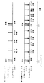
以上の構成のマスターECU100とスレーブECU200によるランプ制御を図3のフローチャートと、図4の第1および第2の制御ラインL1,L2における制御信号の伝送タイミング図を参照して説明する。この伝送タイミング図は時間軸上においてマスターECU100とスレーブECU200との間で矢印方向に信号が伝送されることを表している図である。時点t1において自動車のイグニッションスイッチがオンされると、マスターECU100はCANラインL0を通して入力される信号に基づいてこれを認識し、直ちにライン監視・設定部105から所定の監視信号をまず第1制御ラインL1を通してスレーブECU200に伝送する。スレーブECU200はライン監視部205においてこの監視信号を受信し、当該監視信号に対応した確認信号を第1制御ラインL1を通して返送する。マスターECU100のライン監視・設定部105はこの返送された確認信号を受信し、これを監視信号と対比することによって第1制御ラインL1が正常であるか否かを判定する(S11)。次いで、ライン監視・設定部105は監視信号を第2制御ラインL2を通してスレーブECU200に伝送し、スレーブECU200から第2制御ラインL2を通して返送された確認信号に基づいて第2制御ラインL2が正常であるか否かを判定する(S12)。
Lamp control by the
第1および第2の制御ラインL1,L2がいずれも正常のときには、ライン監視・設定部105は第1および第2制御ラインL1,L2を基準設定のままとする。すなわち、第1制御ラインL1により点灯制御信号、配光制御信号、レベリング制御信号を伝送し、第2制御ラインL2によりスイブル制御信号を伝送するように割り当てを設定する(S13)。
When both the first and second control lines L1 and L2 are normal, the line monitoring /
しかる上で、ランプスイッチのオン・オフ信号に基づく第1次の点灯制御信号がCANラインL0を通してマスターECU100に入力されると点灯制御部101は点灯又は消灯するための第2次の点灯制御信号を生成し、この第2次の点灯制御信号に基づいて左ヘッドランプLHLのLED22を点灯又は消灯する。これと同時に当該第2次の点灯制御信号を第1制御ラインL1を介してスレーブECU200に伝送する。スレーブECU200の点灯制御部201はこの伝送されてきた第2次の点灯制御信号に基づいて右ヘッドランプRHLのLEDを点灯又は消灯する(S14)。
Accordingly, when the first lighting control signal based on the lamp switch on / off signal is input to the
配光制御についても同様であり、ディマースイッチのオン・オフ信号に基づく第1次の配光制御信号がCANラインL0を通してマスターECU100に入力されると、配光制御部102が第2次の配光制御信号を生成し、この配光制御信号に基づいて左ヘッドランプLHLの可変シェード3を制御する。この制御では、アクチュエータ33によってシェード体32の傾動位置を設定し、LED22から出射された光の一部を遮光し、あるいは遮光しないようにすることでロービーム配光又はハイビーム配光に制御する。これと同時に第2次の配光制御信号を第1制御ラインL1を介してスレーブECU200に伝送することで、スレーブECU200の配光制御部202は右ヘッドランプRHLの可変シェードを制御して配光制御を実行する。
The same applies to the light distribution control. When the first light distribution control signal based on the ON / OFF signal of the dimmer switch is input to the
レベリング制御については、車高センサから検出されるピッチ角に基づいて得られる第1次のレベリング制御信号がCANラインL0を通してマスターECU100入力されると、マスターECU100のレベリング制御部103が第2次のレベリング制御信号を生成し、このレベリング制御信号に基づいて左ヘッドランプLHLのレベリング機構4を制御する。この制御では、モータ41でスクリューロッド42を軸転し、ナット43を前後方向に移動して傾動フレーム6の傾動角度を調整することでランプ光軸Lxを上下方向に偏向制御してレベリング制御を実行する。これと同時に第2次のレベリング制御信号を第1制御ラインL1を介してスレーブECU200に伝送することで、スレーブECU200のレベリング制御部203が右ヘッドランプRHLのレベリング機構を制御してレベリング制御を実行する(S14)。
Regarding the leveling control, when a primary leveling control signal obtained based on the pitch angle detected from the vehicle height sensor is input to the
さらに、操舵角センサから検出される操舵角がCANラインL0を通してマスターECU100に入力されると、マスターECU100のスイブル制御部104が第2次のスイブル制御信号を生成し、左ヘッドランプLHLのスイブル機構5を制御する。この制御ではスイブル駆動ユニット51により回転出力軸52を軸転させることで、これに連結されているランプユニット2を水平方向に回動し、ランプ光軸Lxを左右方向に偏向制御してスイブル制御を実行する。これと同時に得られたスイブル制御信号を、ここでは第2制御ラインL2を介してスレーブECU200に伝送する。スレーブECU200のスイブル制御部204はこの第2次のスイブル制御信号を受けて右ヘッドランプRHLのスイブル機構を制御してスイブル制御を実行する(S15)。
Further, when the steering angle detected from the steering angle sensor is input to the
なお、各ECU100,200の各制御部におけるそれぞれの制御において、特にレベリング制御とスイブル制御においては、各ヘッドランプLHL,RHLに設けたレベリング機構とスイブル機構から出力されてくる検出信号に基づいてこれらをフィードバック制御するように構成することが可能であることは言うまでもない。
In each control in each control unit of each
このように、第1と第2の制御ラインL1,L2がいずれも正常のときには、点灯制御、配光制御、レベリング制御については第1制御ラインL1を介して各制御信号を伝送して各制御を実行し、スイブル制御については第2制御ラインL2を介してスイブル制御信号を伝送してスイブル制御を実行している。これは図4の伝送タイミング図から判るように、スイブル制御は操舵変化に追従した制御であって時間軸上での制御頻度が高く、時間当たりの伝送容量が大きいため、第2制御ラインL2をスイブル制御の専用ラインとして割り当てている。一方、点灯制御、配光制御、レベリング制御はスイブル制御に比較して時間軸上での制御頻度が低く、時間当たりの伝送容量が小さいため、これらの制御信号を第1制御ラインL1で共用して伝送するように割り当てている。これにより、点灯制御、配光制御、レベリング制御、スイブル制御をそれぞれ好適に実行することができる。 As described above, when the first and second control lines L1 and L2 are all normal, each control signal is transmitted via the first control line L1 for the lighting control, light distribution control, and leveling control. The swivel control is executed by transmitting a swivel control signal via the second control line L2. As can be seen from the transmission timing diagram of FIG. 4, the swivel control is a control that follows the steering change, the control frequency is high on the time axis, and the transmission capacity per time is large. Assigned as a dedicated line for swivel control. On the other hand, lighting control, light distribution control, and leveling control are less frequently controlled on the time axis than swivel control, and the transmission capacity per hour is small. Therefore, these control signals are shared by the first control line L1. Assigned to be transmitted. Thereby, lighting control, light distribution control, leveling control, and swivel control can each be suitably executed.
ステップS11において第1制御ラインが正常であるが、ステップS12において第2制御ラインL2が異常であると判定したとき、すなわち第2制御ラインL2が断線、地絡する等して第2制御ラインL2を通して返送された確認信号がマスターECU100にまで伝送されず、あるいは伝送された場合でも監視信号と一致しないときには、スイブル制御については停止するとともに(S16)、ステップS13での第1および第2の制御ラインL1,L2の基準設定を行った上で、第1制御ラインL1による点灯制御、配光制御、レベリング制御はそのまま継続する。このスイブル制御の停止は、例えば、ランプ光軸Lxを現在のスイブル角位置に固定する、あるいは予め設定していたデフォルトのスイブル角位置に制御することが考えられる。また、このスイブル制御の停止は、左右ヘッドランプLHL,RHLの光照射の整合性を得るために、第2次のスイブル制御信号を伝送することができないスレーブECU200側の右ヘッドランプRHLはもとより、第2次のスイブル制御信号が得られているマスターECU100側の左ヘッドランプLHLについても行うことが好ましい。これにより、以降はスイブル制御は行われないが、安全走行に最低限必要とされる左右のヘッドランプの点灯制御ないし配光制御は確保される。また、レベリング制御も確保される。
When it is determined in step S11 that the first control line is normal but the second control line L2 is abnormal in step S12, that is, the second control line L2 is disconnected, grounded, or the like. If the confirmation signal sent back through is not transmitted to the
一方、ステップS11において第1制御ラインL1が異常と判定したときには、ステップS21において第2制御ラインL2が正常であるか否かを判定する。第2制御ラインL2も異常であると判定したときには、ライン監視・設定部105は警報信号を出力する(S25)。これにより、運転者は左右のヘッドランプLHL,RHLが正常にランプ制御されない状態にあることを認識し、適切な対応をとることになる。
On the other hand, when it is determined in step S11 that the first control line L1 is abnormal, it is determined in step S21 whether or not the second control line L2 is normal. When it is determined that the second control line L2 is also abnormal, the line monitoring /
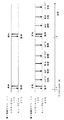
また、ステップS21において第2制御ラインL2が正常であると判定したときには、ライン監視・設定部105は第1制御ラインL1を第2制御ラインL2に切り替える設定を行う(S22)。すなわち、図5にタイミング図を示すように、時刻t1での監視において第1制御ラインL1の異常と第2制御ラインL2の正常が判定されたときには、点灯制御、配光制御、レベリング制御の各制御信号を第2制御ラインL2を通して伝送するように割り当てる。これとともに、ライン監視・設定部105はスイブル制御信号の伝送を停止し、以降はスイブル制御を停止する設定を行う(S23)。このスイブル制御の停止では、前記したようにランプ光軸Lxを現在のスイブル角位置に固定する。あるいは、ランプ光軸Lxを予め設定していたデフォルトのスイブル角位置に制御する。これにより、以降はスイブル制御は行われないが、正常な第2制御ラインL2を通して安全走行に最低限必要とされる左右のヘッドランプLHL,RHLの点灯制御、配光制御は確保される。また、レベリング制御も確保される(S24)。
When it is determined in step S21 that the second control line L2 is normal, the line monitoring /
このように、第1および第2の制御ラインL1,L2が正常なときには、ランプ制御での時間当たりの伝送容量が大きいスイブル制御信号を第2制御ラインL2に専用に割り当て、他の伝送容量が小さい点灯制御、配光制御、レベリング制御の各制御信号を第1制御ラインL1に割り当てている。そして、車両の安全走行における重要度の高いランプ制御、すなわちこの実施形態では左右のヘッドランプの点灯・消灯を制御する点灯制御が割り当てられた第1制御ラインL1が異常と判定されたときには、当該点灯制御の制御信号を正常な第2制御ラインL2に切り替える。このとき第2制御ラインL2に割り当てられていた重要度の低い制御信号、ここではスイブル制御信号については以降の伝送を停止して第2制御ラインL2を空けるので、第2制御ラインL2を利用して点灯制御信号を伝送する妨げになることはない。これにより、第2制御ラインL2を用いて重要度の高い点灯制御信号の伝送を確保することができ、フェイルセイフを確保した左右のヘッドランプLHL,RHLの好適なランプ制御が実現できる。 As described above, when the first and second control lines L1 and L2 are normal, a swivel control signal having a large transmission capacity per hour in the lamp control is exclusively assigned to the second control line L2, and other transmission capacities are obtained. Small control signals for lighting control, light distribution control, and leveling control are assigned to the first control line L1. When the first control line L1 to which lamp control with high importance in safe driving of the vehicle, that is, lighting control for controlling lighting / extinguishing of the left and right headlamps in this embodiment is determined, is determined to be abnormal. The control signal for lighting control is switched to the normal second control line L2. At this time, the control signal of low importance assigned to the second control line L2, in this case, the swivel control signal, stops the subsequent transmission and frees up the second control line L2. Therefore, the second control line L2 is used. Therefore, it does not hinder the transmission of the lighting control signal. Accordingly, it is possible to ensure the transmission of the lighting control signal with high importance using the second control line L2, and it is possible to realize suitable lamp control of the left and right headlamps LHL and RHL that ensure fail-safe.
なお、この実施形態では、ライン監視・設定部105とライン監視部205による第1および第2の制御ラインL1,L2の監視は定期的に行っており、図4に示したように最初の監視を行った時刻t1から所定の時間を経過した時刻t2でも同様に両制御ラインL1,L2の監視を行っている。この時刻t2での監視においても制御ラインL1,L2が正常のときには同様にして点灯制御、配光制御、レベリング制御、スイブル制御を実行する。また、図6に伝送タイミング図を示すように、時刻t2において第1制御ラインL1の異常が検出されたときには、この時刻t2においてスイブル制御を停止し、点灯制御、配光制御、レベリング制御の各制御信号の伝送を第2制御ラインL2に切り替えて以降の各制御を行うようにする。
In this embodiment, the first and second control lines L1 and L2 are regularly monitored by the line monitoring /
以上の実施形態では、重要度の高い点灯制御信号の伝送が割り当てられている第1制御ラインL1が異常のときに、スイブル制御を停止して第2制御ラインL2を空けているが、スイブル制御を完全に停止するのではなく、スイブル制御の頻度を低減するように制御することも可能である。例えば、図7に伝送タイミング図を示すように、時刻t1で第1制御ラインL1の異常を検出したときに点灯制御、配光制御、レベリング制御を第2制御ラインL2に割り当てているが、第2制御ラインL2におけるスイブル制御信号の伝送頻度を通常時よりも低減して時間軸上に空き領域を設け、この空き領域を利用して点灯制御信号、配光制御信号、レベリング制御信号を伝送している。この場合にはスイブル制御も最低限必要な範囲で確保することができる。ただし、スイブル制御の制御頻度は正常時よりも低減されるので、安全走行に必要とされる場合にのみ、例えば操舵角が極めて大きく操舵されたような場合についてのみスイブル制御を行うように制御のタイミングを設定するようにすればよい。 In the above embodiment, when the first control line L1 to which transmission of the lighting control signal with high importance is assigned is abnormal, the swivel control is stopped and the second control line L2 is opened. It is also possible to perform control so as to reduce the frequency of swivel control instead of completely stopping the control. For example, as shown in the transmission timing diagram of FIG. 7, when an abnormality is detected in the first control line L1 at time t1, lighting control, light distribution control, and leveling control are assigned to the second control line L2. (2) The transmission frequency of the swivel control signal in the control line L2 is reduced compared to the normal time to provide an empty area on the time axis, and the lighting control signal, the light distribution control signal, and the leveling control signal are transmitted using this empty area. ing. In this case, swivel control can be ensured within the minimum necessary range. However, since the control frequency of swivel control is reduced as compared with normal time, control is performed so that swivel control is performed only when necessary for safe driving, for example, when the steering angle is extremely large. What is necessary is just to set a timing.
前記実施形態ではランプ制御として左右のヘッドランプに対する点灯制御、配光制御、レベリング制御、スイブル制御を行う例について説明したが、複数の異なるランプ制御の各制御信号を複数本の制御ラインを通してマスターECUからスレーブECUに伝送してランプ制御を行うランプ制御装置であれば、実施形態に記載のランプ制御に限定されるものではない。すなわち、本発明は、重要度の異なる複数のランプ制御を行う場合に、最も重要度の高い制御を割り当てている制御ラインが異常になったときに、この制御を正常な制御ラインに割り当てるようにすればよい。当該正常な制御ラインの空き領域に余裕がある場合には、さらに重要度の高い順序で他の制御を割り当てるようにすればよい。また、制御ラインは2本に限られるものではなく、各ECUに制御の余裕がある場合には3本以上の制御ラインを備えるランプ制御装置についても本発明を同様に適用することができる。 In the embodiment, the example of performing the lighting control, the light distribution control, the leveling control, and the swivel control for the left and right headlamps as the lamp control has been described. However, the master ECU transmits each control signal of a plurality of different lamp controls through a plurality of control lines. The lamp control device is not limited to the lamp control described in the embodiment as long as the lamp control device performs the lamp control by transmitting to the slave ECU. That is, according to the present invention, when performing control of a plurality of lamps having different importance levels, when the control line to which the control with the highest importance level is assigned becomes abnormal, the control is assigned to a normal control line. do it. If there is a vacant area in the normal control line, other controls may be assigned in order of higher importance. Further, the number of control lines is not limited to two, and the present invention can be similarly applied to a lamp control device including three or more control lines when each ECU has a control margin.
本発明のランプ制御の対象となるランプはヘッドランプに限られるものではなく複数個のランプを同じ点灯状態となるようにランプ制御することが要求される車両用のランプであれば適用可能である。 The lamp that is subject to lamp control according to the present invention is not limited to a headlamp, but can be applied to any vehicle lamp that is required to perform lamp control so that a plurality of lamps are in the same lighting state. .
本発明は複数のランプの1つにマスターECUを備え、他のランプにスレーブECUを備え、ランプ制御信号をマスターECUからスレーブECUに伝送してこれらのランプをランプ制御する構成の車両のランプに採用することが可能である。 The present invention provides a vehicle lamp having a master ECU in one of a plurality of lamps, a slave ECU in another lamp, and a lamp control signal transmitted from the master ECU to the slave ECU to control these lamps. It is possible to adopt.
LHL,RHL 左右のヘッドランプ
L0 CANライン
L1,L2 LINライン(制御ライン)
1 ランプハウジング
2 ランプユニット
3 可変シェード
4 レベリング機構
5 スイブル機構
100 マスターECU
200 スレーブECU
101,201 点灯制御部
102,202 配光制御部
103,203 レベリング制御部
104,204 スイブル制御部
105 ライン監視・設定部
205 ライン監視部
106,206 LINインターフェース
107 CANインターフェース
LHL, RHL Left and right headlamps L0 CAN line L1, L2 LIN line (control line)
DESCRIPTION OF
200 Slave ECU
101, 201
Claims (6)
The master control means is connected to the CAN line of the vehicle, controls the one headlamp based on a secondary lamp control signal generated from a signal input through the CAN line, and 6. The vehicle according to claim 3, wherein a second lamp control signal is transmitted to the slave control means through the first and second control lines configured as LIN lines. Lamp control device.
Priority Applications (1)
| Application Number | Priority Date | Filing Date | Title |
|---|---|---|---|
| JP2012161068A JP2014019347A (en) | 2012-07-20 | 2012-07-20 | Lamp control device of vehicle |
Applications Claiming Priority (1)
| Application Number | Priority Date | Filing Date | Title |
|---|---|---|---|
| JP2012161068A JP2014019347A (en) | 2012-07-20 | 2012-07-20 | Lamp control device of vehicle |
Publications (1)
| Publication Number | Publication Date |
|---|---|
| JP2014019347A true JP2014019347A (en) | 2014-02-03 |
Family
ID=50194718
Family Applications (1)
| Application Number | Title | Priority Date | Filing Date |
|---|---|---|---|
| JP2012161068A Pending JP2014019347A (en) | 2012-07-20 | 2012-07-20 | Lamp control device of vehicle |
Country Status (1)
| Country | Link |
|---|---|
| JP (1) | JP2014019347A (en) |
Cited By (4)
| Publication number | Priority date | Publication date | Assignee | Title |
|---|---|---|---|---|
| JP2017162805A (en) * | 2016-03-02 | 2017-09-14 | ヴァレオ ビジョンValeo Vision | Anti-dazzle headlamp |
| JP2018086913A (en) * | 2016-11-29 | 2018-06-07 | 株式会社小糸製作所 | Lighting control device for vehicle lamp |
| DE102021117552A1 (en) | 2020-07-10 | 2022-01-13 | Koito Manufacturing Co., Ltd. | Lamp control device for a vehicle |
| WO2023189151A1 (en) * | 2022-03-31 | 2023-10-05 | 株式会社小糸製作所 | Vehicle lamp system |
-
2012
- 2012-07-20 JP JP2012161068A patent/JP2014019347A/en active Pending
Cited By (7)
| Publication number | Priority date | Publication date | Assignee | Title |
|---|---|---|---|---|
| JP2017162805A (en) * | 2016-03-02 | 2017-09-14 | ヴァレオ ビジョンValeo Vision | Anti-dazzle headlamp |
| JP7034593B2 (en) | 2016-03-02 | 2022-03-14 | ヴァレオ ビジョン | Anti-glare headlamp |
| JP2018086913A (en) * | 2016-11-29 | 2018-06-07 | 株式会社小糸製作所 | Lighting control device for vehicle lamp |
| WO2018101060A1 (en) * | 2016-11-29 | 2018-06-07 | 株式会社小糸製作所 | Vehicle lamp lighting control device |
| US10933809B2 (en) | 2016-11-29 | 2021-03-02 | Koito Manufacturing Co., Ltd. | Vehicle lamp lighting control device |
| DE102021117552A1 (en) | 2020-07-10 | 2022-01-13 | Koito Manufacturing Co., Ltd. | Lamp control device for a vehicle |
| WO2023189151A1 (en) * | 2022-03-31 | 2023-10-05 | 株式会社小糸製作所 | Vehicle lamp system |
Similar Documents
| Publication | Publication Date | Title |
|---|---|---|
| JP2014019347A (en) | Lamp control device of vehicle | |
| US9199573B2 (en) | Vehicle light distribution control device and vehicle light distribution control method | |
| CN108528322B (en) | Headlamp control system and vehicle | |
| JP6359949B2 (en) | Vehicle lamp system | |
| JP2016088223A (en) | Vehicular lighting fixture system | |
| JP5119116B2 (en) | Vehicle headlamp device | |
| JP2012162105A (en) | Vehicular headlight device | |
| JP4356935B2 (en) | Vehicle headlamp | |
| JP2006182100A (en) | Vehicular lighting system | |
| JP2014024422A (en) | Lamp control device of vehicle | |
| EP2399776A2 (en) | Vehicle headlamp system, control device, and vehicle headlamp | |
| JP2009283443A (en) | Headlight device for vehicle | |
| JP2010137616A (en) | Lighting system for vehicle | |
| US20220009404A1 (en) | Lamp control device for vehicle | |
| JP4333626B2 (en) | Vehicle headlamp device | |
| KR20190132170A (en) | Outer display lighting apparatus of vehicle | |
| JP2017016994A (en) | Vehicle bending light apparatus | |
| JP6711291B2 (en) | Vehicle heads up display | |
| JP5834781B2 (en) | Vehicle lighting device | |
| JP4737075B2 (en) | In-vehicle headlamp light distribution control device and in-vehicle headlamp | |
| JP5407397B2 (en) | Control system | |
| JP2004168209A (en) | Irradiation system and optical axis changing device | |
| JP6608671B2 (en) | Light distribution control system for vehicle headlamps | |
| JP2020001572A (en) | Lighting unit control device | |
| JP4681287B2 (en) | Headlight device provided in automobile and method for controlling the device |