JP2014019089A - Inspection device of sheet-like material - Google Patents
Inspection device of sheet-like material Download PDFInfo
- Publication number
- JP2014019089A JP2014019089A JP2012161219A JP2012161219A JP2014019089A JP 2014019089 A JP2014019089 A JP 2014019089A JP 2012161219 A JP2012161219 A JP 2012161219A JP 2012161219 A JP2012161219 A JP 2012161219A JP 2014019089 A JP2014019089 A JP 2014019089A
- Authority
- JP
- Japan
- Prior art keywords
- sheet
- infrared
- ink
- paper
- printed
- Prior art date
- Legal status (The legal status is an assumption and is not a legal conclusion. Google has not performed a legal analysis and makes no representation as to the accuracy of the status listed.)
- Granted
Links
- 238000007689 inspection Methods 0.000 title claims abstract description 44
- 239000000463 material Substances 0.000 title claims abstract description 21
- 238000003384 imaging method Methods 0.000 claims description 33
- 238000003331 infrared imaging Methods 0.000 claims description 11
- 230000001678 irradiating effect Effects 0.000 claims description 4
- 230000000007 visual effect Effects 0.000 abstract 1
- 239000000976 ink Substances 0.000 description 59
- 230000015654 memory Effects 0.000 description 37
- 238000001514 detection method Methods 0.000 description 11
- 210000000078 claw Anatomy 0.000 description 8
- 238000012937 correction Methods 0.000 description 5
- 238000000034 method Methods 0.000 description 5
- 238000010586 diagram Methods 0.000 description 4
- 238000012546 transfer Methods 0.000 description 4
- 230000003287 optical effect Effects 0.000 description 3
- 239000007788 liquid Substances 0.000 description 2
- 230000002093 peripheral effect Effects 0.000 description 2
- 238000004140 cleaning Methods 0.000 description 1
- 239000003086 colorant Substances 0.000 description 1
- 238000004891 communication Methods 0.000 description 1
- 230000007423 decrease Effects 0.000 description 1
- 230000002950 deficient Effects 0.000 description 1
- 238000009434 installation Methods 0.000 description 1
- 238000007781 pre-processing Methods 0.000 description 1
- 238000003908 quality control method Methods 0.000 description 1
- 239000000758 substrate Substances 0.000 description 1
- 238000011144 upstream manufacturing Methods 0.000 description 1
Images


Classifications
-
- G—PHYSICS
- G01—MEASURING; TESTING
- G01N—INVESTIGATING OR ANALYSING MATERIALS BY DETERMINING THEIR CHEMICAL OR PHYSICAL PROPERTIES
- G01N21/00—Investigating or analysing materials by the use of optical means, i.e. using sub-millimetre waves, infrared, visible or ultraviolet light
- G01N21/84—Systems specially adapted for particular applications
- G01N21/86—Investigating moving sheets
-
- G—PHYSICS
- G07—CHECKING-DEVICES
- G07D—HANDLING OF COINS OR VALUABLE PAPERS, e.g. TESTING, SORTING BY DENOMINATIONS, COUNTING, DISPENSING, CHANGING OR DEPOSITING
- G07D7/00—Testing specially adapted to determine the identity or genuineness of valuable papers or for segregating those which are unacceptable, e.g. banknotes that are alien to a currency
- G07D7/06—Testing specially adapted to determine the identity or genuineness of valuable papers or for segregating those which are unacceptable, e.g. banknotes that are alien to a currency using wave or particle radiation
- G07D7/12—Visible light, infrared or ultraviolet radiation
- G07D7/121—Apparatus characterised by sensor details
-
- B—PERFORMING OPERATIONS; TRANSPORTING
- B41—PRINTING; LINING MACHINES; TYPEWRITERS; STAMPS
- B41F—PRINTING MACHINES OR PRESSES
- B41F33/00—Indicating, counting, warning, control or safety devices
- B41F33/0036—Devices for scanning or checking the printed matter for quality control
-
- G—PHYSICS
- G01—MEASURING; TESTING
- G01N—INVESTIGATING OR ANALYSING MATERIALS BY DETERMINING THEIR CHEMICAL OR PHYSICAL PROPERTIES
- G01N21/00—Investigating or analysing materials by the use of optical means, i.e. using sub-millimetre waves, infrared, visible or ultraviolet light
- G01N21/84—Systems specially adapted for particular applications
- G01N21/88—Investigating the presence of flaws or contamination
- G01N21/8806—Specially adapted optical and illumination features
-
- G—PHYSICS
- G01—MEASURING; TESTING
- G01N—INVESTIGATING OR ANALYSING MATERIALS BY DETERMINING THEIR CHEMICAL OR PHYSICAL PROPERTIES
- G01N21/00—Investigating or analysing materials by the use of optical means, i.e. using sub-millimetre waves, infrared, visible or ultraviolet light
- G01N21/84—Systems specially adapted for particular applications
- G01N21/88—Investigating the presence of flaws or contamination
- G01N21/89—Investigating the presence of flaws or contamination in moving material, e.g. running paper or textiles
-
- G—PHYSICS
- G06—COMPUTING; CALCULATING OR COUNTING
- G06T—IMAGE DATA PROCESSING OR GENERATION, IN GENERAL
- G06T7/00—Image analysis
- G06T7/90—Determination of colour characteristics
-
- H—ELECTRICITY
- H04—ELECTRIC COMMUNICATION TECHNIQUE
- H04N—PICTORIAL COMMUNICATION, e.g. TELEVISION
- H04N5/00—Details of television systems
- H04N5/30—Transforming light or analogous information into electric information
- H04N5/33—Transforming infrared radiation
-
- A—HUMAN NECESSITIES
- A24—TOBACCO; CIGARS; CIGARETTES; SIMULATED SMOKING DEVICES; SMOKERS' REQUISITES
- A24C—MACHINES FOR MAKING CIGARS OR CIGARETTES
- A24C5/00—Making cigarettes; Making tipping materials for, or attaching filters or mouthpieces to, cigars or cigarettes
- A24C5/32—Separating, ordering, counting or examining cigarettes; Regulating the feeding of tobacco according to rod or cigarette condition
- A24C5/34—Examining cigarettes or the rod, e.g. for regulating the feeding of tobacco; Removing defective cigarettes
- A24C5/3412—Examining cigarettes or the rod, e.g. for regulating the feeding of tobacco; Removing defective cigarettes by means of light, radiation or electrostatic fields
-
- G—PHYSICS
- G06—COMPUTING; CALCULATING OR COUNTING
- G06T—IMAGE DATA PROCESSING OR GENERATION, IN GENERAL
- G06T2207/00—Indexing scheme for image analysis or image enhancement
- G06T2207/10—Image acquisition modality
- G06T2207/10016—Video; Image sequence
Abstract
Description
本発明は、通常のインクで印刷された絵柄部分と赤外成分が含まれるインクで印刷された絵柄部分を含むシート状物の検査装置に関するものである。 The present invention relates to an inspection apparatus for a sheet-like object including a pattern portion printed with normal ink and a pattern portion printed with ink containing an infrared component.
この種の検査装置として、従来、本出願人による特許文献1に開示されたようなものがある。 Conventionally, this type of inspection apparatus is disclosed in Patent Document 1 by the present applicant.
これは、無端搬送体に設けられてシート状物の端部を保持するシート状物保持装置と、このシート状物保持装置の移動軌跡の一部に該移動軌跡よって形成されるループの内側へ向けて設けられた円弧状軌跡部と、この円弧状軌跡部の前記ループの内側に設けられた複数個の検査装置と、この円弧状軌跡部の前記ループの外側に設けられたガイドとを備え、前記シート状物は前記円弧状軌跡部に沿って走行中、前記ガイドに案内された状態で前記複数個の検査装置により検査されるものである。 This is because the sheet-like material holding device that is provided on the endless conveyance body and holds the end of the sheet-like material, and inside the loop formed by the movement locus on a part of the movement locus of the sheet-like material holding device. And a plurality of inspection devices provided inside the loop of the arcuate locus part, and a guide provided outside the loop of the arcuate locus part. The sheet-like object is inspected by the plurality of inspection devices while being guided by the guide while traveling along the arcuate locus.
そして、前記検査装置を構成するCCD−ラインカメラ等の複数個の撮像手段とこれらのCCD−ラインカメラ等と対になって設けられるLED照明器等の複数個の光源は、円弧状軌跡部の周囲に放射状に配置される。 A plurality of imaging means such as a CCD-line camera constituting the inspection apparatus and a plurality of light sources such as an LED illuminator provided in a pair with the CCD-line camera are It is arranged radially around.
ところで、紙幣や有価証券等の印刷物では、偽造防止の為、赤外成分が含まれるインクを使用して一部の絵柄を印刷するので、赤外成分が含まれるインクで印刷された絵柄部分と通常のインクで印刷された絵柄部分を検査する場合には、従来、それぞれの絵柄部分を検出して検査する複数個の検査装置(撮像手段や光源等)を、特許文献1のように、シート状物保持装置の移動軌跡の一部に円弧状軌跡部を形成してこの円弧状軌跡部の周囲に放射状に配置したり、検査用の胴を新たに配列したりする必要があった。 By the way, in printed matter such as banknotes and securities, a part of a pattern is printed using ink containing an infrared component in order to prevent forgery. In the case of inspecting a pattern portion printed with normal ink, conventionally, a plurality of inspection devices (imaging means, light sources, etc.) for detecting and inspecting each pattern portion are used as disclosed in Patent Document 1. It has been necessary to form an arcuate trajectory part in a part of the trajectory of the object holding device and arrange it radially around the arcuate trajectory part, or newly arrange an inspection cylinder.
そのため、検査装置用の特別なスペースが必要になり、印刷機が大型化すると共にその為の設備が高くなる、という問題があった。 For this reason, a special space for the inspection apparatus is required, and there is a problem that the size of the printing press increases and the equipment for that purpose increases.
そこで、本発明は、通常のインクで印刷された絵柄部分と赤外成分が含まれるインクで印刷された絵柄部分の検査を省スペース及び省コストで行えるシート状物の検査装置を提供することを目的とする。 Therefore, the present invention provides a sheet-like object inspection apparatus that can inspect a pattern portion printed with normal ink and a pattern portion printed with ink containing an infrared component in a space-saving and cost-saving manner. Objective.
斯かる目的を達成するための本発明に係るシート状物の検査装置は、
通常のインクで印刷された絵柄部分と赤外成分が含まれるインクで印刷された絵柄部分を含むシート状物の検査装置において、
可視光を含む光をシート状物に照射する白色光源と、
赤外線を含む光をシート状物に照射する赤外線光源と、
シート状物を撮像する2台の可視光用撮像手段と、
2台の可視光用撮像手段の視野に入らない位置に設けられ、シート状物を撮像する1台の赤外線用撮像手段と、
シート状物から反射された白色光源及び赤外線光源からの光の可視光をカットし赤外線のみ赤外線用撮像手段に入射するように設けられた赤外線フィルタと、
2台の可視光用撮像手段に入射されたシート状物から反射された白色光源及び赤外線光源からの可視光によって、シート状物の通常のインクで印刷された絵柄部分の適否を判断すると共に、1台の赤外線用撮像手段に入射されたシート状物から反射された白色光源及び赤外線光源からの赤外線によって、シート状物の赤外成分が含まれるインクで印刷された絵柄部分の適否を判断する制御装置と、
を備えたことを特徴とする。
An apparatus for inspecting a sheet-like object according to the present invention for achieving such an object,
In an inspection apparatus for a sheet-like object including a pattern part printed with normal ink and a pattern part printed with ink containing an infrared component,
A white light source that irradiates the sheet-like material with light including visible light;
An infrared light source for irradiating the sheet-like material with light including infrared;
Two visible light imaging means for imaging a sheet-like object;
One infrared imaging means provided at a position not entering the field of view of the two visible light imaging means and imaging a sheet-like object;
An infrared filter provided to cut the visible light from the white light source and the infrared light source reflected from the sheet-like material and to allow only the infrared light to enter the infrared imaging means;
While judging the suitability of the pattern portion printed with the normal ink of the sheet-like material by the visible light from the white light source and the infrared light source reflected from the sheet-like material incident on the two visible light imaging means, The suitability of the pattern portion printed with the ink containing the infrared component of the sheet-like material is determined by the white light source reflected from the sheet-like material incident on one infrared imaging means and the infrared rays from the infrared light source. A control device;
It is provided with.
また、
前記赤外線用撮像手段が、シート幅方向に離間して設けられた2台の可視光用撮像手段の間に設けられている、
ことを特徴とする。
Also,
The infrared imaging means is provided between two visible light imaging means provided separately in the sheet width direction.
It is characterized by that.
また、
前記2台の可視光用撮像手段及び赤外線用撮像手段が、シート状物の撮像面からの距離が等しい位置に設けられている、
ことを特徴とする。
Also,
The two visible light imaging means and the infrared imaging means are provided at the same distance from the imaging surface of the sheet-like object.
It is characterized by that.
本発明に係るシート状物の検査装置によれば、既設の胴配列等を利用して可視光用撮像手段と赤外線用撮像手段をコンパクトに配設して、通常のインクで印刷された絵柄部分と赤外成分が含まれるインクで印刷された絵柄成分を同時にかつ同じ撮像面で検査できるようにしたので、検査装置の省スペース及び省コストが図れる。 According to the sheet-like object inspection apparatus of the present invention, the image portion printed with normal ink is arranged in a compact arrangement of the imaging means for visible light and the imaging means for infrared light using an existing cylinder arrangement or the like. Since the image components printed with the ink including the infrared component can be inspected simultaneously and on the same imaging surface, the space and cost of the inspection apparatus can be saved.
以下、本発明に係るシート状物の検査装置を実施例により図面を用いて詳細に説明する。 DESCRIPTION OF THE PREFERRED EMBODIMENTS Hereinafter, a sheet-shaped inspection apparatus according to the present invention will be described in detail with reference to the drawings by way of examples.
図1は本発明の一実施例を示す検査装置の側面図、図2は同じく検査装置の正面図、図3は同じく制御装置のブロック図、図4は同じく絵柄の説明図、図5は同じく凹版印刷機の全体概略構成図、図6は同じく図5の要部拡大図である。 1 is a side view of an inspection apparatus according to an embodiment of the present invention, FIG. 2 is a front view of the inspection apparatus, FIG. 3 is a block diagram of the control apparatus, FIG. 4 is an explanatory diagram of a pattern, and FIG. FIG. 6 is an enlarged schematic view of the main part of FIG.
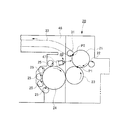
図5に示すように、通常の絵柄のみでなく、番号や印章を印刷する複数の印刷工程の最終印刷機としての凹版印刷機は給紙装置10と印刷装置20と排紙装置30とから概ね構成される。
As shown in FIG. 5, an intaglio printing press as a final printing machine in a plurality of printing steps for printing not only ordinary pictures but also numbers and seals is roughly composed of a
紙(シート状物)Wが積載された給紙装置10には、当該給紙装置10のサッカ機構で上層から一枚ずつ送り出された紙Wを受けて印刷見当を合わせる差板11が連絡している。凹版印刷機の差板11の先端部分には、当該差板11上の紙Wをくわえて揺動するスイング装置12が配設されている。
The
印刷装置20においては、前記スイング装置12に、くわえ爪を周方向に沿って等間隔で3つ配設されて3枚のゴム製のブランケットを取り付けできる、いわゆる3倍胴の圧胴21が渡胴22を介して連絡している。渡胴22には、上記圧胴21の上記くわえ爪と同様なくわえ爪が設けられており、スイング装置12からくわえ替えた紙Wを圧胴21のくわえ爪にくわえ替えさせることができるようになっている。
In the
前記圧胴21には、周方向に沿って3枚の凹版を取り付けできる、いわゆる3倍胴の版胴23が対接している。版胴23の凹版には、周方向に沿って4枚のゴム製のブランケットを取り付けできる、いわゆる4倍胴のインキ集合胴24が対接している。
The
このインキ集合胴24には、圧胴21のブランケットや版胴23の凹版の長さに対応した周面長をなす、いわゆる単一胴のシャブロン胴25が周方向にわたって5つ対接している。これらシャブロン胴25には、インキを供給するインキ装置26がそれぞれ対接している。これらインキ装置26内には、互いに異なる色のインキが各々充填されている。
The
前記版胴23の凹版には、ワイピングローラ27が対接している。このワイピングローラ27は、洗浄液を貯えたワイピングタンク28内に浸漬している。
A
排紙装置30においては、前記圧胴21に排紙胴31が対接している。そして、排紙胴31に同軸をなして設けられている図示しない一対のスプロケットと排紙装置30の最後部に配置された一対のスプロケット32との間には、排紙チェーン33がエンドレスに巻回されている。排紙チェーン33には、図示しない排紙爪が設けられている。排紙チェーン33の走行方向下流側には、排紙台34が複数設けられている。
In the
従って、前記給紙装置10から差板11上へ紙Wを一枚ずつ送り出すと、当該紙Wはスイング装置12によって渡胴22に受け渡され、この渡胴22のくわえ爪から圧胴21のくわえ爪にくわえ替えられて圧胴21に受け渡される。
Accordingly, when the paper W is sent out from the
他方、各インキ装置26のインキは、シャブロン胴25を介してインキ集合胴24に転写されて版胴23の前記凹版面上に供給され、当該インキの余剰分がワイピングローラ27で取り除かれた後、圧胴21と対接するときに、当該圧胴21に保持されている前記紙Wに前記インキが転写されて印刷される。尚、前記ワイピングローラ27で取り除かれた余剰のインキは、前記ワイピングタンク28内でワイピング液により当該ワイピングローラ27から洗浄除去される。
On the other hand, the ink of each
このようにして前記版胴23からインキを転写されて印刷された前記紙Wは、前記圧胴21の回転に伴って走行移動することにより、当該圧胴21の周面上において後述する検査装置40によりその印刷品質が検査される。
The paper W printed with the ink transferred from the
続いて、前記紙Wは、前記圧胴21から排紙胴31に受け渡された後、排紙装置30の排紙チェーン33の排紙爪に把持されて搬送され、排紙台34上に排紙される。
Subsequently, the paper W is transferred from the
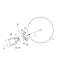
そして、本実施例では、図6に示すように、前記圧胴21における版胴23との対接箇所(印刷箇所P1参照)より同圧胴21の回転方向下流側でかつ排紙胴31との対接箇所(紙受け渡し箇所P2参照)よりも同圧胴21の回転方向上流側の周面に対向して、通常のインク(以下、可視インクという)で印刷された絵柄部分と赤外成分が含まれるインク(以下、IRインクという)で印刷された絵柄部分を含む紙Wの検査装置40が設けられる。
In the present embodiment, as shown in FIG. 6, the
前記検査装置40は、図1及び図2に示すように、先ず可視インク検査用として、可視光を含む光を紙Wに照射する一対の白色LED照明器(白色光源)41a,41bと、紙Wを撮像する2台の可視用カラーカメラ(可視光用撮像手段)42A,42Bとが設けられる。
As shown in FIG. 1 and FIG. 2, the
次に、IRインク検査用として、赤外線を含む光を紙Wに照射する一対のIR‐LED照明器(赤外線光源)43a,43bと、紙Wを撮像する1台のIR用モノクロカメラ(赤外線用撮像手段)44と、紙Wから反射された白色LED照明器41a,41b及びIR‐LED照明器43a,43bからの光の可視光以下の波長の光をカットし赤外線のみIR用モノクロカメラ44に入射するIRフィルタ(赤外線フィルタ)45とが設けられる。
Next, for IR ink inspection, a pair of IR-LED illuminators (infrared light sources) 43a and 43b for irradiating the paper W with light including infrared rays, and one IR monochrome camera for imaging the paper W (for infrared rays) Imaging means) 44 and the light from the
そして、2台の可視用カラーカメラ42A,42Bに入射された紙Wから反射された白色LED照明器41a,41b及びIR‐LED照明器43a,43bからの可視光によって、紙Wの可視インクで印刷された絵柄部分とIRインクで印刷された絵柄部分の適否を判断すると共に、1台のIR用モノクロカメラ44に入射された紙Wから反射された白色LED照明器41a,41b及びIR‐LED照明器43a,43bからの赤外線によって、紙WのIRインクで印刷された絵柄部分の形の適否を判断する制御装置46が設けられる。
The visible light from the
前記IR用モノクロカメラ44は、紙(シート)幅方向に離間して設けられた2台の可視用カラーカメラ42A,42Bの中間に設けられ、2台の可視用カラーカメラ42A,42Bの視野に入らない設置位置となっている。図2中L1は可視用カラーカメラ42Aの検査幅、L2は可視用カラーカメラ42Bの検査幅、L3はIR用モノクロカメラ44の検査幅をそれぞれ示す。
The
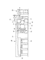
また、2台の可視用カラーカメラ42A,42BとIR用モノクロカメラ44は、各々が圧胴21の中心線に対して法線方向Nに設けられ、紙Wの撮像面を垂直方向から撮像すると共に紙Wの撮像面からの距離が等しい位置に設けられている。即ち、三つのカメラ42A,42B及び44が圧胴21の胴軸線と平行な一直線上に支持フレーム47を介して本機フレーム48(図6参照)に支持されるのである。尚、白色LED照明器41a,41bとIR‐LED照明器43a,43bも図示しない支持フレームを介して本機フレーム48に支持される。
The two
次に、図3を用いて、本実施例による検査装置40の光学的および電気的構成について説明する。検査装置40は、紙Wの可視インクで印刷された絵柄部分を撮像する上述した2台の可視用カラーカメラ42A,42Bと紙WのIRインクで印刷された絵柄部分を撮像する上述したIR用モノクロカメラ44と、これらカメラ42A,42B及び44からの撮像出力に基づいて紙Wに印刷された絵柄の印刷品質を検査する制御装置46とを備える。これらカメラ42A,42B及び44は、レンズ42Aa,42Ba及び44aを含む光学系および光学系を介して結像される画像を電気信号に変換するCCD(Charge Coupled Device)42Ab,42Bb及び44bを有する。
Next, the optical and electrical configuration of the
制御装置46は、基準画像信号を記憶する基準メモリ50A(IR用モノクロカメラ用),50B(可視用カラーカメラ用)と、検出画像信号を記憶する検出メモリ51A(IR用モノクロカメラ用),51B(可視用カラーカメラ用)と、基準メモリ50A,50B及び検出メモリ51A,51Bへの書き込み及び読み出しを制御するメモリコントローラ55と、基準メモリ50A,50B及び検出メモリ51A,51Bから読み出された各々の2つの信号の許容レベル差が設定される判定レベル設定回路52A(IR用モノクロカメラ用),52B(可視用カラーカメラ用)と、判定レベル設定回路52A,52Bに設定された許容レベル差を考慮して各々の2つの信号を比較する比較回路53と、CCD42Ab,42Bb及び44bの出力を増幅するアンプ56と、アンプ56の出力をアナログ・デジタル変換してメモリコントローラ55に出力するA/Dコンバータ57と、アンプ56のゲインを調整する補正回路58と、CCD42Ab,42Bb及び44bを制御するCCDコントローラ59とを備える。
The
基準メモリ50A,50Bは、印刷ジョブの開始時に、紙Wに正常に可視インクで印刷された絵柄部分とIRインクで印刷された絵柄部分から読み込まれた基準画像データを記憶する。尚、基準画像データは、印刷ジョブ毎に異なった基準画像データが基準メモリ50A,50Bに記憶される。検出メモリ51A,51Bは、検査対象の紙Wから読み込まれた検出画像データを記憶する。
The reference memories 50 </ b> A and 50 </ b> B store reference image data read from a pattern portion that is normally printed with visible ink and a pattern portion printed with IR ink on the paper W at the start of a print job. As the reference image data, different reference image data for each print job is stored in the
メモリコントローラ55は、基準メモリ50A,50Bおよび検出メモリ51A,51Bへのデータの書き込みおよび読み出しを制御する。判定レベル設定回路52A(IR用モノクロカメラ用),52B(可視用カラーカメラ用)は、基準メモリ50A,50Bから読み出された基準画像データと検出メモリ51A,51Bから読み出された検出画像データとの許容レベル差を予め設定する。
The
比較回路53は、メモリコントローラ55によって読み出された基準画像データと検出画像データとのレベル差が判定レベル設定回路52A,52Bに設定された許容レベル差以上の場合に、品質が不良であることを示す信号を出力する。即ち、CCD42Ab,42Bb及び44bの各画素に対応する基準画像データと検出画像データとを逐一比較することにより各画素に対応する両データのレベルを比較し、一個でも許容差以上となっている場合には不良信号を出力する。
The
具体的には、比較回路53は、基準メモリ50A,50Bから読み出された基準画像データと検出メモリ51A,51Bから読み出された検出画像データとを一画素毎に順次比較する第1の比較動作を行う。次に、比較回路53は、第1の比較動作によって得られた各々の2つの信号のレベル差と、判定レベル設定回路52A,52Bから出力された許容レベル差とを比較する第2の比較動作を行う。第2の比較動作の結果、各々の2つの信号のレベル差が許容レベル差よりも大きい場合に、比較回路53は検査対象である紙Wに可視インクで印刷された絵柄部分とIRインクで印刷された絵柄部分がそれぞれ不良であることを示す不良信号を出力する。
Specifically, the
補正回路58は、圧胴21の回転速度に合わせてアンプ56のゲインを調整する。即ち、カメラ42A,42B及び44に同一光量が入射した場合でも、圧胴21の回転速度が速いほどCCD42Ab,42Bb及び44bの出力レベルが小さくなる。このため、補正回路58によって回転速度の影響を除去する。メモリコントローラ55、比較回路53、補正回路58、CCDコントローラ59には位相信号が供給される。メモリコントローラ55には基準値メモリ信号が供給される。メモリコントローラ55、比較回路53には判定スタート信号が供給される。
The
位相信号は、圧胴21の回転位相を検出するロータリエンコーダ(図示せず)の出力信号から生成される。位相信号は、圧胴21の1回転毎に立ち上がる基準パルスと、圧胴21の一定回転毎に立ち上がるクロックパルスとからなる。基準値メモリ信号は、メモリコントローラ55を介して基準メモリ50A,50Bに基準画像データの読み込みを行うための信号であり、オペレータによる基準値メモリスイッチ(図示せず)の操作により供給される。判定スタート信号は、基準画像データと検出画像データとの比較動作開始を指示する信号であり、オペレータによる判定スタートスイッチ(図示せず)の操作により供給される。
The phase signal is generated from the output signal of a rotary encoder (not shown) that detects the rotational phase of the
このような構成において、品質検査工程の前処理として、紙Wに正常に可視インクで印刷された絵柄部分とIRインクで印刷された絵柄部分にそれぞれ対応する基準画像データの取り込みが行われる。まず、紙Wを用いた試し刷り中にオペレータが紙Wの印刷状態を確認する。印刷状態が良であることが確認された場合、基準値メモリスイッチ(図示せず)の操作により基準値メモリ信号の制御装置46への供給が開始される。圧胴21の基準位置を表す基準信号がロータリエンコーダより出力されると、圧胴21に保持/搬送される紙Wから基準画像データの取り込みが開始され、基準メモリ50A,50Bへ記憶される。
In such a configuration, as pre-processing of the quality inspection process, reference image data corresponding to a pattern portion that is normally printed on paper W with visible ink and a pattern portion that is printed with IR ink are captured. First, the operator confirms the printing state of the paper W during the trial printing using the paper W. When it is confirmed that the printing state is good, supply of a reference value memory signal to the
圧胴21に保持/搬送される紙Wの基準画像データが基準メモリ50A,50Bに記憶された後、判定スタート信号により判定処理が開始される。この判定処理において、まず基準画像データの読み込みと同様に、圧胴21の回転に伴い検出メモリ51A,51Bに対応する圧胴21に保持/搬送される紙Wの検出画像データが読み込まれる。次に、判定処理時に読み込まれた検出画像データと予め記憶された基準画像データとが比較され、両データのレベル値が許容レベル差内に収まっているかによって、紙Wの可視インクで印刷された絵柄部分の適否と紙WのIRインクで印刷された絵柄部分の適否がそれぞれ判定される。
After the reference image data of the paper W held / conveyed by the
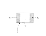
例えば、IR用モノクロカメラ44によれば、図4に示すように、検査対象である紙Wの多数の小切れ(紙幣や有価証券等)Waにおいて、可視インクで印刷された絵柄部分VEは、白色LED照明器41a,41b及びIR‐LED照明器43a,43bから撮像面に照射されて反射した可視光がIRフィルタ45で全てカットされ、撮像面に照射され、そのまま反射した赤外線が入射されるため、その全てが白く写る。
For example, according to the
そして、可視インクで印刷された絵柄部分VEの両側に位置してIRインクで印刷された絵柄部分IEa,IEbは、白色LED照明器41a,41b及びIR‐LED照明器43a,43bから撮像面に照射されIRインクによって吸収されながら反射した赤外線がIRフィルタ45を通してIR用モノクロカメラ44に入射されるため、黒く鮮明に写る。
The pattern portions IEa and IEb printed on the both sides of the pattern portion VE printed with the visible ink and printed with the IR ink are transferred from the
これらの結果、IRインクで印刷された絵柄部分IEa,IEbの形の詳細な検査が可能となるのである。また、可視用カラーカメラ42A,42Bでは、可視インクで印刷された絵柄部分VEとIRインクで印刷された絵柄部分IEa,IEbの両方が、それぞれの部分を人が目で見た時と同じ色で撮像するため、両方の部分の詳細な検査が可能となるのである。
As a result, detailed inspection of the shapes of the picture portions IEa and IEb printed with IR ink is possible. Further, in the
このように、可視光と赤外線とは波長が異なるので、可視インクで印刷された絵柄部分VEとIRインクで印刷された絵柄部分IEa,IEbとが同時に同じ撮像面で検査が可能となる。 Thus, since visible light and infrared rays have different wavelengths, the pattern portion VE printed with visible ink and the pattern portions IEa and IEb printed with IR ink can be simultaneously inspected on the same imaging surface.
このようにして本実施例によれば、可視インクで印刷された絵柄部分VEとIRインクで印刷された絵柄部分IEa,IEbの検査を、専用の検査胴を設けることなく既設の圧胴21上で、同時にかつ同じ撮像面で検査できるようにしたので、検査装置40の省スペース化により印刷機の大型化が回避できると共に部品点数の削減等により設備の省コスト化が図れる。
In this way, according to the present embodiment, the pattern portion VE printed with visible ink and the pattern portions IEa and IEb printed with IR ink are inspected on the existing
尚、本発明は上記実施例に限定されず、本発明の要旨を逸脱しない範囲で、胴配列やインキ色の変更等各種変更が可能であることはいうまでもない。 Needless to say, the present invention is not limited to the above-described embodiments, and various changes such as changes in the cylinder arrangement and ink color are possible without departing from the scope of the present invention.
本発明に係るシート状物の検査装置は、品質管理が重要な紙幣や証券印刷等の印刷を行う特殊印刷機に用いて有効である。 The sheet-like object inspection apparatus according to the present invention is effective for use in a special printing machine that performs printing such as banknotes and securities printing whose quality control is important.
10 給紙装置
11 差板
12 スイング装置
20 印刷装置
21 圧胴
22 渡胴
23 版胴
24 インキ集合胴
25 シャブロン胴
26 インキ装置
27 ワイピングローラ
28 ワイピングタンク
30 排紙装置
31 排紙胴
32 スプロケット
33 排紙チェーン
34 排紙台
40 検査装置
41a,41b 白色LED照明器(白色光源)
42A,42B 可視用カラーカメラ(可視光用撮像手段)
42Aa,42Ba レンズ
42Ab,42Bb CCD(Charge Coupled Device)
43a,43b IR‐LED照明器(赤外線光源)
44 IR用モノクロカメラ(赤外線用撮像手段)
44a レンズ
44b CCD(Charge Coupled Device)
45 IRフィルタ(赤外線フィルタ)
46 制御装置
50A 基準メモリ(IR用モノクロカメラ用)
50B 基準メモリ(可視用カラーカメラ用)
51A 検出メモリ(IR用モノクロカメラ用)
51B 検出メモリ(可視用カラーカメラ用)
52A 判定レベル設定回路(IR用モノクロカメラ用)
52B 判定レベル設定回路(可視用カラーカメラ用)
53 比較回路
55 メモリコントローラ
56 アンプ
57 A/Dコンバータ
58 補正回路
59 CCDコントローラ
W 紙(シート状物)
Wa 小切れ(紙幣や有価証券等)
P1 印刷箇所
P2 紙受け渡し箇所
VE 可視インクで印刷された絵柄部分
IEa,IEb IRインクで印刷された絵柄部分
L1 可視用カラーカメラ42Aの検査幅
L2 可視用カラーカメラ42Bの検査幅
L3 IR用モノクロカメラ44の検査幅
DESCRIPTION OF
42A, 42B Visible color camera (imaging means for visible light)
42Aa, 42Ba Lens 42Ab, 42Bb CCD (Charge Coupled Device)
43a, 43b IR-LED illuminator (infrared light source)
44 IR monochrome camera (infrared imaging means)
45 IR filter (infrared filter)
46
50B reference memory (for visible color camera)
51A detection memory (for IR monochrome camera)
51B Detection memory (for visible color camera)
52A judgment level setting circuit (for IR monochrome camera)
52B judgment level setting circuit (for visible color camera)
53
Wa small slices (banknotes, securities, etc.)
P1 Print location P2 Paper delivery location VE Pattern portion printed with visible ink IEa, IEb Pattern portion printed with IR ink L1 Inspection width of
Claims (3)
可視光を含む光をシート状物に照射する白色光源と、
赤外線を含む光をシート状物に照射する赤外線光源と、
シート状物を撮像する2台の可視光用撮像手段と、
2台の可視光用撮像手段の視野に入らない位置に設けられ、シート状物を撮像する1台の赤外線用撮像手段と、
シート状物から反射された白色光源及び赤外線光源からの光の可視光をカットし赤外線のみ赤外線用撮像手段に入射するように設けられた赤外線フィルタと、
2台の可視光用撮像手段に入射されたシート状物から反射された白色光源及び赤外線光源からの可視光によって、シート状物の通常のインクで印刷された絵柄部分の適否を判断すると共に、1台の赤外線用撮像手段に入射されたシート状物から反射された白色光源及び赤外線光源からの赤外線によって、シート状物の赤外成分が含まれるインクで印刷された絵柄部分の適否を判断する制御装置と、
を備えたことを特徴とするシート状物の検査装置。 In an inspection apparatus for a sheet-like object including a pattern part printed with normal ink and a pattern part printed with ink containing an infrared component,
A white light source that irradiates the sheet-like material with light including visible light;
An infrared light source for irradiating the sheet-like material with light including infrared;
Two visible light imaging means for imaging a sheet-like object;
One infrared imaging means provided at a position not entering the field of view of the two visible light imaging means and imaging a sheet-like object;
An infrared filter provided to cut the visible light from the white light source and the infrared light source reflected from the sheet-like material and to allow only the infrared light to enter the infrared imaging means;
While judging the suitability of the pattern portion printed with the normal ink of the sheet-like material by the visible light from the white light source and the infrared light source reflected from the sheet-like material incident on the two visible light imaging means, The suitability of the pattern portion printed with the ink containing the infrared component of the sheet-like material is determined by the white light source reflected from the sheet-like material incident on one infrared imaging means and the infrared rays from the infrared light source. A control device;
An inspection apparatus for a sheet-like material, comprising:
ことを特徴とする請求項1に記載のシート状物の検査装置。 The infrared imaging means is provided between two visible light imaging means provided separately in the sheet width direction.
The sheet-like object inspection apparatus according to claim 1.
ことを特徴とする請求項1に記載のシート状物の検査装置。 The two visible light imaging means and the infrared imaging means are provided at the same distance from the imaging surface of the sheet-like object.
The sheet-like object inspection apparatus according to claim 1.
Priority Applications (4)
| Application Number | Priority Date | Filing Date | Title |
|---|---|---|---|
| JP2012161219A JP5959001B2 (en) | 2012-07-20 | 2012-07-20 | Sheet inspection equipment |
| EP13176413.6A EP2687839B1 (en) | 2012-07-20 | 2013-07-12 | Inspection apparatus for sheet |
| CN201310300721.XA CN103568550B (en) | 2012-07-20 | 2013-07-17 | Sheet-shaped check device |
| US13/946,102 US9170206B2 (en) | 2012-07-20 | 2013-07-19 | Inspection apparatus for sheet |
Applications Claiming Priority (1)
| Application Number | Priority Date | Filing Date | Title |
|---|---|---|---|
| JP2012161219A JP5959001B2 (en) | 2012-07-20 | 2012-07-20 | Sheet inspection equipment |
Publications (2)
| Publication Number | Publication Date |
|---|---|
| JP2014019089A true JP2014019089A (en) | 2014-02-03 |
| JP5959001B2 JP5959001B2 (en) | 2016-08-02 |
Family
ID=48790249
Family Applications (1)
| Application Number | Title | Priority Date | Filing Date |
|---|---|---|---|
| JP2012161219A Expired - Fee Related JP5959001B2 (en) | 2012-07-20 | 2012-07-20 | Sheet inspection equipment |
Country Status (4)
| Country | Link |
|---|---|
| US (1) | US9170206B2 (en) |
| EP (1) | EP2687839B1 (en) |
| JP (1) | JP5959001B2 (en) |
| CN (1) | CN103568550B (en) |
Families Citing this family (9)
| Publication number | Priority date | Publication date | Assignee | Title |
|---|---|---|---|---|
| CN103895373A (en) * | 2014-03-25 | 2014-07-02 | 中国大冢制药有限公司 | Infusion soft bag sign printing method |
| JP2017127976A (en) * | 2016-01-18 | 2017-07-27 | 株式会社小森コーポレーション | Printer |
| EP3270144B1 (en) * | 2016-04-12 | 2021-12-15 | Nippon Steel Corporation | Inspection object imaging apparatus, inspection object imaging method, surface inspection apparatus, and surface inspection method |
| JP6842615B2 (en) * | 2016-07-13 | 2021-03-17 | 株式会社小森コーポレーション | Print quality inspection equipment |
| CN107341900B (en) * | 2017-07-04 | 2019-10-22 | 广州市银科电子有限公司 | A kind of bill anti-counterfeit discrimination method based on infrared printing ink mark intelligent recognition |
| EP3715124A1 (en) | 2019-03-26 | 2020-09-30 | Inopaq Technologies Sàrl | Printed sheet inspection system and sheet-fed printing press comprising the same |
| CN110033549B (en) * | 2019-04-09 | 2020-06-16 | 惠州Tcl移动通信有限公司 | Mobile terminal and mobile terminal control method |
| CN112729246B (en) * | 2020-12-08 | 2022-12-16 | 广东省科学院智能制造研究所 | Black surface object depth image measuring method based on binocular structured light |
| CN114705691B (en) * | 2022-06-06 | 2022-09-06 | 深圳向一智控科技有限公司 | Industrial machine vision control method and device |
Citations (6)
| Publication number | Priority date | Publication date | Assignee | Title |
|---|---|---|---|---|
| JPH10272761A (en) * | 1997-03-28 | 1998-10-13 | Toppan Printing Co Ltd | Hue fluctuation control apparatus for printed matter |
| JP2003166943A (en) * | 2001-12-04 | 2003-06-13 | Toppan Printing Co Ltd | Print inspection method |
| JP2006518454A (en) * | 2003-02-10 | 2006-08-10 | カーベーアー−ジオリ ソシエテ アノニム | Detection device |
| JP2006240097A (en) * | 2005-03-03 | 2006-09-14 | Tokyo Printing & Equipment Trading Co Ltd | Equipment and method for inspecting printed matter |
| JP2007103665A (en) * | 2005-10-04 | 2007-04-19 | Yamaha Motor Co Ltd | Inspection device and printer for mounting substrate |
| JP2009210559A (en) * | 2008-02-08 | 2009-09-17 | Toshiba Corp | Defacement degree determination apparatus and defacement degree determination method for printed matter |
Family Cites Families (21)
| Publication number | Priority date | Publication date | Assignee | Title |
|---|---|---|---|---|
| GB8311795D0 (en) * | 1983-04-29 | 1983-06-02 | De La Rue Syst | Detecting luminescent security features |
| US5767980A (en) * | 1995-06-20 | 1998-06-16 | Goss Graphic Systems, Inc. | Video based color sensing device for a printing press control system |
| JP2000296602A (en) * | 1999-04-15 | 2000-10-24 | Kita Denshi Corp | Apparatus for detecting printing error |
| DE19930154A1 (en) * | 1999-06-30 | 2001-01-04 | Voith Paper Patent Gmbh | Monitor to determine the formation and/or formation index of a running paper or cardboard web has a LED array to illuminate the web and matrix camera(s) linked to a common server through a frame grab card or computer |
| JP2001187444A (en) * | 2000-01-05 | 2001-07-10 | Dainippon Printing Co Ltd | Printed matter checking device |
| CN100498306C (en) * | 2003-11-21 | 2009-06-10 | 中国印钞造币总公司 | Device and method used for detecting flake material infrared image printing quality |
| CN1898704B (en) * | 2004-02-12 | 2010-04-21 | 日本电产科宝株式会社 | Inspection device |
| CN1670512B (en) * | 2004-03-17 | 2010-05-05 | 中国印钞造币总公司 | Integrated debugging bench for detecting image quality of sheet-like material |
| CN100565593C (en) * | 2007-12-14 | 2009-12-02 | 中国印钞造币总公司 | A kind of counterfeit-prevention quality detection device |
| US20100033708A1 (en) * | 2008-08-11 | 2010-02-11 | Kriz Michael H | Optical Inspection System Using UV Light for Automated Inspection of Holograms |
| JP5379525B2 (en) * | 2009-03-19 | 2013-12-25 | 株式会社小森コーポレーション | Sheet quality inspection equipment |
| CN101850652B (en) * | 2009-03-19 | 2015-03-11 | 小森公司 | Quality inspection apparatus for sheet-shaped matter |
| CN201397307Y (en) * | 2009-04-13 | 2010-02-03 | 北京凌云光视数字图像技术有限公司 | Composite checking device for large-piece fluorescent and infrared printing quality |
| JP2010277252A (en) * | 2009-05-27 | 2010-12-09 | Toshiba Corp | Paper sheet handling apparatus |
| DE102009048002A1 (en) * | 2009-10-02 | 2011-04-07 | Beb Industrie-Elektronik Ag | Method and device for checking the degree of soiling of banknotes |
| CN101976475A (en) * | 2010-06-08 | 2011-02-16 | 北京新岸线软件科技有限公司 | Paper money identification method and device |
| CN101976477A (en) * | 2010-10-25 | 2011-02-16 | 深圳市怡化电脑有限公司 | Multispectral multi-angle identification method and device for detecting optically variable ink and hologrphic image |
| CN202142123U (en) * | 2011-07-05 | 2012-02-08 | 深圳大学 | Bank note/ bill discriminating device |
| JP5536150B2 (en) * | 2011-08-09 | 2014-07-02 | キヤノン・コンポーネンツ株式会社 | Image sensor unit and image reading apparatus |
| CN102568079A (en) * | 2011-12-12 | 2012-07-11 | 中钞实业有限公司 | Note intelligent identifier and note anti-counterfeiting method based on multispectral characteristic |
| US8976250B2 (en) * | 2012-05-01 | 2015-03-10 | Apple Inc. | Lens inspection system |
-
2012
- 2012-07-20 JP JP2012161219A patent/JP5959001B2/en not_active Expired - Fee Related
-
2013
- 2013-07-12 EP EP13176413.6A patent/EP2687839B1/en not_active Not-in-force
- 2013-07-17 CN CN201310300721.XA patent/CN103568550B/en not_active Expired - Fee Related
- 2013-07-19 US US13/946,102 patent/US9170206B2/en not_active Expired - Fee Related
Patent Citations (6)
| Publication number | Priority date | Publication date | Assignee | Title |
|---|---|---|---|---|
| JPH10272761A (en) * | 1997-03-28 | 1998-10-13 | Toppan Printing Co Ltd | Hue fluctuation control apparatus for printed matter |
| JP2003166943A (en) * | 2001-12-04 | 2003-06-13 | Toppan Printing Co Ltd | Print inspection method |
| JP2006518454A (en) * | 2003-02-10 | 2006-08-10 | カーベーアー−ジオリ ソシエテ アノニム | Detection device |
| JP2006240097A (en) * | 2005-03-03 | 2006-09-14 | Tokyo Printing & Equipment Trading Co Ltd | Equipment and method for inspecting printed matter |
| JP2007103665A (en) * | 2005-10-04 | 2007-04-19 | Yamaha Motor Co Ltd | Inspection device and printer for mounting substrate |
| JP2009210559A (en) * | 2008-02-08 | 2009-09-17 | Toshiba Corp | Defacement degree determination apparatus and defacement degree determination method for printed matter |
Also Published As
| Publication number | Publication date |
|---|---|
| US20140022379A1 (en) | 2014-01-23 |
| JP5959001B2 (en) | 2016-08-02 |
| EP2687839A3 (en) | 2015-06-24 |
| CN103568550A (en) | 2014-02-12 |
| EP2687839A2 (en) | 2014-01-22 |
| US9170206B2 (en) | 2015-10-27 |
| EP2687839B1 (en) | 2016-12-21 |
| CN103568550B (en) | 2017-05-31 |
Similar Documents
| Publication | Publication Date | Title |
|---|---|---|
| JP5959001B2 (en) | Sheet inspection equipment | |
| JP5420363B2 (en) | Image inspection apparatus, image inspection method, and image recording apparatus | |
| EP2711691B1 (en) | Inspection apparatus for sheet | |
| JP2011148254A (en) | Light source control device and ink drying device | |
| US20050284324A1 (en) | Print defect displaying method and print defect displaying apparatus | |
| US8835876B2 (en) | Inspection apparatus for sheet | |
| JP2014177050A (en) | Method of inspecting conditions of print plate and/or blanket | |
| JP2015105846A (en) | Checkup apparatus for sheet-shaped objects | |
| JP2006192680A (en) | Inspecting device of printed matter | |
| JP2002310799A (en) | Method and device for detecting concentration of color ink of printed matter | |
| JP5468504B2 (en) | Print quality inspection device | |
| US9531936B2 (en) | Camera system, colour measuring system, and offset printing press | |
| JP4365735B2 (en) | Printed material measuring device | |
| JP2006110962A (en) | Printing density measuring device | |
| JP2009160816A (en) | Aboard-the-printer checking method of printing plate or blanket | |
| JP2021535017A (en) | How to manufacture printing machines and securities products or securities intermediate products equipped with inspection equipment | |
| JP2008229874A (en) | Printing equipment | |
| JP6192197B2 (en) | Sheet inspection method | |
| WO2017126537A1 (en) | Printer | |
| JP2014059255A (en) | Inspection device for sheet-like material | |
| JP2005212142A (en) | Printer | |
| JP2008119964A (en) | Top-bottom reversed printing sensing apparatus for sheet-fed printing press and top-bottom reversed printing sensing method | |
| JP2006205437A (en) | Damping water control method and printing device | |
| JP2005297346A (en) | Controlling method of color tone | |
| JP2014020982A (en) | Sheet-like object inspection device |
Legal Events
| Date | Code | Title | Description |
|---|---|---|---|
| A621 | Written request for application examination |
Free format text: JAPANESE INTERMEDIATE CODE: A621 Effective date: 20150615 |
|
| TRDD | Decision of grant or rejection written | ||
| A01 | Written decision to grant a patent or to grant a registration (utility model) |
Free format text: JAPANESE INTERMEDIATE CODE: A01 Effective date: 20160531 |
|
| RD03 | Notification of appointment of power of attorney |
Free format text: JAPANESE INTERMEDIATE CODE: A7423 Effective date: 20160531 |
|
| A61 | First payment of annual fees (during grant procedure) |
Free format text: JAPANESE INTERMEDIATE CODE: A61 Effective date: 20160616 |
|
| R150 | Certificate of patent or registration of utility model |
Ref document number: 5959001 Country of ref document: JP Free format text: JAPANESE INTERMEDIATE CODE: R150 |
|
| LAPS | Cancellation because of no payment of annual fees |