JP2014018786A - Scale removing apparatus and humidifier - Google Patents

Scale removing apparatus and humidifier Download PDF

Info

Publication number
JP2014018786A
JP2014018786A JP2012163385A JP2012163385A JP2014018786A JP 2014018786 A JP2014018786 A JP 2014018786A JP 2012163385 A JP2012163385 A JP 2012163385A JP 2012163385 A JP2012163385 A JP 2012163385A JP 2014018786 A JP2014018786 A JP 2014018786A
Authority
JP
Japan
Prior art keywords
water
inner cylinder
water supply
scale remover
outer cylinder
Prior art date
Legal status (The legal status is an assumption and is not a legal conclusion. Google has not performed a legal analysis and makes no representation as to the accuracy of the status listed.)
Pending
Application number
JP2012163385A
Other languages
Japanese (ja)
Inventor
Akira Kato
亮 加藤
Hiroyuki Miyamoto
博幸 宮本
Current Assignee (The listed assignees may be inaccurate. Google has not performed a legal analysis and makes no representation or warranty as to the accuracy of the list.)
Panasonic Corp
Original Assignee
Panasonic Corp
Priority date (The priority date is an assumption and is not a legal conclusion. Google has not performed a legal analysis and makes no representation as to the accuracy of the date listed.)
Filing date
Publication date
Application filed by Panasonic Corp filed Critical Panasonic Corp
Priority to JP2012163385A priority Critical patent/JP2014018786A/en
Publication of JP2014018786A publication Critical patent/JP2014018786A/en
Pending legal-status Critical Current

Links

Images

Landscapes

  • Air Humidification (AREA)
  • Treatment Of Water By Ion Exchange (AREA)

Abstract

PROBLEM TO BE SOLVED: To provide a scale removing apparatus for obtaining water from which ions of group 2 elements are removed for a long period of time or in a large amount, and a humidifier with the scale removing apparatus installed thereon.SOLUTION: A scale removing apparatus 1 which is constituted of an external cylinder 2 and an inner cylinder 3 having a central axis identical to each other, and an upper surface and a lower surface closing the cylinders, which has an air hole 16 having a diameter smaller than that of the inner cylinder 3 at the center of the upper surface, a water intake hole 14 having a diameter equal to or smaller than that of the inner cylinder 3 at the center of the lower surface, and an inlet 10 on the entire periphery of a side wall of the external cylinder 2 and an outlet 12 on the entire periphery of a side wall of the inner cylinder 3, and which has granular ion exchange resin 6 filled between the external cylinder 2 and the inner cylinder 3, is obtained. In addition, a humidifier which has the scale removing apparatus 1 fixed to a tank cap 23 and provided in a water supply tank 17 is obtained.

Description

本発明は、スケールの元となる成分を除去した水を作り出すスケール除去器および、その水を気化させて部屋へのスケールの散布や加湿フィルタおよびトレイへのスケールの固着を防止する加湿機に関するものである。   The present invention relates to a scale remover that produces water from which scale components have been removed, and a humidifier that vaporizes the water to prevent spraying of the scale in a room and the fixing of the scale to a humidifying filter and tray. It is.

従来、スケールを除去した水を用いて加湿する加湿機が知られている(例えば、特許文献1参照)。   Conventionally, a humidifier is known that humidifies using water from which scale has been removed (see, for example, Patent Document 1).

以下、その加湿機について図16を参照しながら説明する。図16に示すように加湿機は給水タンク101、イオンフィルタ102、加湿トレイ103、加湿モジュール104、送風機110で構成される。給水タンク101中の水はジグザグの通水路106を有し、通水路106の中に粒状の強酸性イオン交換樹脂107が充填されたイオンフィルタ102を通水方向105に沿って通過する。   Hereinafter, the humidifier will be described with reference to FIG. As shown in FIG. 16, the humidifier includes a water supply tank 101, an ion filter 102, a humidifying tray 103, a humidifying module 104, and a blower 110. The water in the water supply tank 101 has a zigzag water passage 106, and passes along the water direction 105 through the ion filter 102 in which the granular strong acid ion exchange resin 107 is filled in the water passage 106.

その際に水に含まれるカルシウムイオンやマグネシウムイオンなどの第2族元素からなるイオン(以下第2族元素イオンとする)がナトリウムイオンと交換する形で強酸性のイオン交換樹脂107に捕捉され、水中から除去される。第2族元素イオンが除去された水は加湿トレイ103に行き、加湿モジュール104と接触する。水は加湿モジュール104を構成する透湿性チューブ108の壁を透過して透湿性チューブ108の内側へと送られる。   At that time, ions composed of Group 2 elements such as calcium ions and magnesium ions contained in water (hereinafter referred to as Group 2 element ions) are captured by the strongly acidic ion exchange resin 107 in the form of exchange with sodium ions, Removed from the water. The water from which the group 2 element ions have been removed goes to the humidifying tray 103 and comes into contact with the humidifying module 104. Water passes through the wall of the moisture permeable tube 108 constituting the humidification module 104 and is sent to the inside of the moisture permeable tube 108.

そこで送風機110から通気方向109に沿って送り込まれた空気と接触し、気化して空気と混ざり、加湿される。水中の第2族元素イオンはイオンフィルタ102によって除去されているため、加湿トレイ103の水が乾いて第2族元素イオンが濃縮され、空気中の二酸化炭素や水中の炭酸イオンと結合して不溶性の炭酸塩となって加湿トレイ103に固着することを防ぐことができる。   Then, it comes into contact with the air sent from the blower 110 along the ventilation direction 109, vaporizes, mixes with the air, and is humidified. Since the group 2 element ions in the water are removed by the ion filter 102, the water in the humidifying tray 103 is dried and the group 2 element ions are concentrated and combined with carbon dioxide in the air and carbonate ions in the water to be insoluble. Can be prevented from adhering to the humidifying tray 103.

また、透湿性チューブ108の壁面に浸透した第2族元素イオンが炭酸塩となって透湿性チューブ108の壁面を目詰まらせ、加湿性能を低下させるという不具合を軽減することができる。   Further, it is possible to alleviate the problem that the group 2 element ions that have permeated the wall surface of the moisture permeable tube 108 become carbonate and clog the wall surface of the moisture permeable tube 108 to reduce the humidification performance.

特開2008−89211号公報(第12頁、図3)Japanese Patent Laying-Open No. 2008-89211 (page 12, FIG. 3)

特許文献1に記載される加湿機に搭載されるイオンフィルタは、図から察するに小さな出入り口および直方体の形状と長方形の通水断面を有する。そのため、長方形の通水断面の隅々まで通水されず、そのため充填した全てのイオン交換樹脂を第2族元素イオンの捕捉に用いることができず、第2族元素イオンの除去性能が早く低下するという課題を有する。   The ion filter mounted on the humidifier described in Patent Document 1 has a small entrance / exit and a rectangular parallelepiped shape and a rectangular water cross section as can be seen from the figure. Therefore, water does not flow to every corner of the rectangular water flow cross section, so that all of the ion exchange resin filled cannot be used for trapping the Group 2 element ions, and the performance of removing the Group 2 element ions decreases quickly. Have the problem of

また、通水速度を制御できないため、給水タンクの水に含まれる第2族元素イオンを十分に除去しきれないという課題を有する。また、塩水を通水してナトリウムイオンを捕捉し再生する際に通水速度が速すぎて再生が十分に行えない、もしくは再生にたくさんの塩水を要するという課題を有する。   Moreover, since a water flow rate cannot be controlled, it has the subject that the group 2 element ion contained in the water of a water supply tank cannot fully be removed. In addition, when salt water is passed and sodium ions are captured and regenerated, there is a problem that the water flow rate is too high to perform regeneration sufficiently, or a large amount of salt water is required for regeneration.

そこで、本発明のスケール除去器は、加湿に用いる水の中に含まれる第2族元素イオンの除去率を長期間に渡って高く維持し、また、少量の塩水で再生することを目的とするものである。また、本発明の加湿機は、コンパクトな形状を保ちながら加湿フィルタや加湿トレイへのスケールの固着を防止し、加湿性能の低下を防止し加湿トレイの清潔さを維持することを目的とするものである。   Therefore, the scale remover of the present invention aims to maintain the removal rate of the group 2 element ions contained in the water used for humidification high for a long period of time and to regenerate with a small amount of salt water. Is. Further, the humidifier of the present invention aims to prevent the scale from adhering to the humidifying filter and the humidifying tray while maintaining a compact shape, to prevent the deterioration of the humidifying performance and to maintain the cleanliness of the humidifying tray. It is.

そして、この目的を達成するために、本発明のスケール除去器は、中心軸と高さを同じくする外筒および内筒と、この外筒および内筒の開口をふさぐ上面、下面からなり、前記上面の中央部には前記内筒よりも径が小さい空気孔を、前記下面の中央部には前記内筒よりも径が小さい取水孔を、前記外筒の側壁には複数の支柱で分割された複数の開口で構成される、スケールを含んだ処理液を流入させる流入口を、前記内筒の側壁には複数の支柱で分割された複数の開口で構成される、前記処理液を流出させる流出口を有し、前記外筒と前記内筒の間に粒状のイオン交換樹脂を充填し、前記流入口および前記流出口に前記イオン交換樹脂よりも目の細かいメッシュ材を設けることにより初期の目的を達成するものである。   In order to achieve this object, the scale remover of the present invention comprises an outer cylinder and an inner cylinder that have the same height as the central axis, and an upper surface and a lower surface that block the opening of the outer cylinder and the inner cylinder. An air hole having a diameter smaller than that of the inner cylinder is formed in a central portion of the upper surface, a water intake hole having a diameter smaller than that of the inner cylinder is formed in a central portion of the lower surface, and a side wall of the outer cylinder is divided by a plurality of support columns. An inflow port configured to include a plurality of openings into which a processing liquid containing a scale is introduced, and the processing liquid including a plurality of openings divided by a plurality of support columns on the side wall of the inner cylinder are allowed to flow out. It has an outlet, is filled with granular ion exchange resin between the outer cylinder and the inner cylinder, and is provided with a mesh material finer than the ion exchange resin at the inlet and outlet. It achieves its purpose.

また、本発明の加湿機は、上記スケール除去器を給水タンク内かつ給水タンクの蓋の裏に設けることにより初期の目的を達成するものである。   The humidifier of the present invention achieves the initial purpose by providing the scale remover in the water supply tank and behind the lid of the water supply tank.

本発明のスケール除去器は、外筒側壁の全周に設けられた入口から入った水が、中心方向へと粒状のイオン交換樹脂の間を通過し、外筒と中心軸を同じくする内筒の全周に設けられた出口から出る。したがって粒状のイオン交換樹脂が充填された領域全てが余すところなく通水経路になり、かつ全ての通水経路が同じ長さとなるため、長期間高い除去率を維持しながら水中の第2族元素イオンを除去することができる。   The scale remover of the present invention is an inner cylinder in which water entering from the inlet provided on the entire circumference of the outer cylinder side wall passes between the granular ion exchange resins in the central direction, and has the same central axis as the outer cylinder. Exit from the exit all around. Therefore, the entire region filled with the granular ion exchange resin becomes a water passage, and all the water passages have the same length, so that the Group 2 element in water while maintaining a high removal rate for a long time. Ions can be removed.

(a)本発明の実施の形態1のスケール除去器の上面図、(b)同スケール除去器の側面図(A) Top view of the scale remover of Embodiment 1 of the present invention, (b) Side view of the scale remover 図1(a)の一点破線Aにおける同スケール除去器の正面断面を示す構成図The block diagram which shows the front cross section of the scale remover in the dashed-dotted line A of Fig.1 (a) 図1(b)の一点破線Bにおける同スケール除去器の上面断面を示す構成図The block diagram which shows the upper surface cross section of the scale remover in the dashed-dotted line B of FIG.1 (b) 同スケール除去器の上斜視図Top perspective view of the scale remover 同スケール除去器の下斜視図Bottom perspective view of the scale remover 図4の一点破線Aにおける同スケール除去器の斜視断面図FIG. 4 is a perspective sectional view of the scale remover taken along one-dot broken line A in FIG. 同外筒を示す構成図Configuration diagram showing the outer cylinder 同内筒下面複合体を示す構成図Configuration diagram showing the inner cylinder lower surface composite 同上蓋を示す構成図Configuration diagram showing the same lid 同スポンジ体を示す構成図Configuration diagram showing the sponge body 本発明の実施の形態2の加湿機を示す断面構成図Sectional block diagram which shows the humidifier of Embodiment 2 of this invention. 同加湿フィルタを示す構成図Configuration diagram showing the humidification filter 同再生台を示す構成図Configuration diagram showing the playback stand 同再生台の上に自立させた給水タンクを示す構成図Schematic diagram showing a water supply tank made independent on the same regeneration stand 本発明の実施の形態1のスケール除去器の第2族元素イオン除去率を示すグラフThe graph which shows the group 2 element ion removal rate of the scale remover of Embodiment 1 of this invention 従来の加湿機を示す構成図Configuration diagram showing a conventional humidifier

以下、本実施の形態について図面を参照しながら説明する。   Hereinafter, the present embodiment will be described with reference to the drawings.

(実施の形態1)
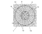
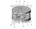
外筒2、内筒3と下面4とを一体化させた内筒下面複合体5、イオン交換樹脂6、上蓋7、スポンジ体8からなるスケール除去器1の2面図を図1に、図1の一点破線Aによる正面断面図を図2に、図1の一点破線Bによる上面断面図を図3に示す。また、イオン交換樹脂6およびスポンジ体8を省いたスケール除去器1の上からの斜視図を図4に、下からの斜視図を図5に、図4の一点破線Aによる斜視断面図を図6に示す。また、外筒2の構成図を図7に、内筒下面複合体5の構成図を図8に、上蓋7の構成図を図9に、スポンジ体の構成図を図10に示す。
(Embodiment 1)
FIG. 1 is a two-sided view of a scale remover 1 comprising an outer cylinder 2, an inner cylinder lower surface composite 5 in which an inner cylinder 3 and a lower surface 4 are integrated, an ion exchange resin 6, an upper lid 7, and a sponge body 8. 2 is a front cross-sectional view taken along one-dot broken line A, and FIG. 3 is a top cross-sectional view taken along one-dot broken line B in FIG. 4 is a perspective view from above of the scale remover 1 excluding the ion exchange resin 6 and the sponge body 8, FIG. 5 is a perspective view from below, and FIG. It is shown in FIG. Further, FIG. 7 shows a configuration diagram of the outer cylinder 2, FIG. 8 shows a configuration diagram of the inner cylinder lower surface composite body 5, FIG. 9 shows a configuration diagram of the upper lid 7, and FIG. 10 shows a configuration diagram of the sponge body.

本実施の形態のスケール除去器1は図4、5および6に示すように外筒2、内筒下面複合体5、上蓋7の3つの部品によって骨格が形成されており、内筒下面複合体5と外筒2を接合し、図2および図3に示すように中心軸を同じくする外筒2および内筒3の間に直径およそ0.3〜1mmのイオン交換樹脂6が隙間なく充填されている。そして開いている上面を上蓋7で塞いだ構造となっている。   As shown in FIGS. 4, 5 and 6, the scale remover 1 of the present embodiment has a skeleton formed by three parts of an outer cylinder 2, an inner cylinder lower surface complex 5, and an upper lid 7. 5 and the outer cylinder 2 are joined, and an ion exchange resin 6 having a diameter of about 0.3 to 1 mm is filled between the outer cylinder 2 and the inner cylinder 3 having the same central axis as shown in FIGS. ing. The open upper surface is closed with the upper lid 7.

また、内筒3の内側上部には図10に示すようなスポンジ体8が埋め込まれている。スポンジ体8は3次元的な網目形状を有しており通気性および通水性を有する。内筒3の内側下部は例えばバルブが上がって内筒3の内部にまで入ってきてもいいように空けている。外筒2は外筒支柱9を残して側壁全周がくりぬかれており、これが水の入口10となる。   Further, a sponge body 8 as shown in FIG. 10 is embedded in the inner upper portion of the inner cylinder 3. The sponge body 8 has a three-dimensional network shape and has air permeability and water permeability. The inner lower part of the inner cylinder 3 is vacant so that, for example, the valve may go up and enter the inner cylinder 3. The outer cylinder 2 is hollowed around the entire side wall, leaving the outer cylinder column 9, and this is the water inlet 10.

また、内筒3も同様に内筒支柱11を残して側壁全周がくりぬかれており、これが水の出口12となる。入口10および出口12にはイオン交換樹脂6よりも目の小さいメッシュ材13が張り巡らされており、水は通してもイオン交換樹脂6が外部にこぼれないようになっている。   Similarly, the inner cylinder 3 is also hollowed around the entire side wall, leaving the inner cylinder column 11, which becomes the water outlet 12. A mesh material 13 having a mesh smaller than that of the ion exchange resin 6 is stretched around the inlet 10 and the outlet 12 so that the ion exchange resin 6 does not spill outside even if water passes therethrough.

上記構成において、第2族元素イオンを含む水は外筒2の全周に設けられた入口10からスケール除去器1の中に入り、内筒3の全周に設けられた出口12へと向かって上から見て中心方向へと進む。そして外筒2および内筒3の間のイオン交換樹脂6が充填された領域を、粒状のイオン交換樹脂6どうしの隙間を縫うように通過する。   In the above configuration, water containing group 2 element ions enters the scale remover 1 from the inlet 10 provided on the entire circumference of the outer cylinder 2 and travels toward the outlet 12 provided on the entire circumference of the inner cylinder 3. Go from the top toward the center. And it passes through the area | region where the ion exchange resin 6 between the outer cylinder 2 and the inner cylinder 3 was filled so that the clearance gap between the granular ion exchange resins 6 might be sewn.

イオン交換樹脂6はイオン結合によってナトリウムイオンを保持するスルホン酸基を内部に有しており、水と接触することによって水に含まれるカルシウムイオンやマグネシウムイオンなどの第2族元素イオンをスルホン酸基によって捕捉し、代わりに当初保持していたナトリウムイオンを放出する。   The ion exchange resin 6 has therein a sulfonic acid group that retains sodium ions by ionic bonds, and when contacted with water, group 2 element ions such as calcium ions and magnesium ions contained in the water are converted into sulfonic acid groups. Instead, the sodium ions originally retained are released.

このような仕組みで炭酸カルシウムや炭酸マグネシウムといった不溶性塩の原因となる第2族元素イオンを除去した水を得ることができる。第2族元素イオンが除去された水はその後に内筒3の全周に設けられた出口12から出て内筒3の内側に入り、さらに下面4に設けられた取水孔14へと導出される。   With such a mechanism, it is possible to obtain water from which Group 2 element ions that cause insoluble salts such as calcium carbonate and magnesium carbonate are removed. The water from which the group 2 element ions have been removed then exits from the outlet 12 provided on the entire circumference of the inner cylinder 3 and enters the inside of the inner cylinder 3, and is further led to a water intake hole 14 provided on the lower surface 4. The

ちなみに単位量あたりのイオン交換樹脂6が第2族元素イオンを捕捉できる量は限られており、限界量を捕捉しきった後は高濃度の塩化ナトリウム水溶液を通水してナトリウムイオンを補足し、第2族元素イオンを脱離させる必要がある。これを再生という。また、再生に使用した水は第2族元素イオンを多く含むため、加湿などに使用せずに廃棄する必要がある。   By the way, the amount that the ion exchange resin 6 per unit amount can capture the Group 2 element ions is limited, and after the limit amount has been captured, sodium ions are supplemented by passing a high-concentration sodium chloride aqueous solution, It is necessary to desorb group 2 element ions. This is called playback. Moreover, since the water used for regeneration contains a large amount of group 2 element ions, it is necessary to discard the water without using it for humidification.

ここで第2族元素イオンの捕捉量を最大にする、もしくは充填したイオン交換樹脂6全てを最大限まで再生するには外筒2および内筒3の間の、イオン交換樹脂6が充填された領域全てが余すところなく通水経路になり、かつ全ての通水経路が同じ長さとなる構造が必要である。   Here, the ion exchange resin 6 between the outer cylinder 2 and the inner cylinder 3 was filled in order to maximize the trapping amount of the group 2 element ions or to regenerate all of the filled ion exchange resin 6 to the maximum. It is necessary to have a structure in which all the areas become water passages and all the water passages have the same length.

図2および図3に示すように、本実施の形態のスケール除去器1は通水方向15に沿って外筒2側壁全周に設けられた入口10から、出口12の存在する中心方向へと通水する。ここで外筒2および内筒3の中心軸が同じであるため外筒2全周に設けられたどの入口10から入っても出口12までの通水経路の長さが同じになる。また同時にイオン交換樹脂6が充填された領域全てが通水経路となる。   As shown in FIG. 2 and FIG. 3, the scale remover 1 of the present embodiment extends from the inlet 10 provided on the entire circumference of the side wall of the outer cylinder 2 along the water flow direction 15 to the central direction where the outlet 12 exists. Pass water. Here, since the central axes of the outer cylinder 2 and the inner cylinder 3 are the same, the length of the water flow path to the outlet 12 is the same regardless of which inlet 10 provided in the entire circumference of the outer cylinder 2 is entered. At the same time, the entire region filled with the ion exchange resin 6 becomes a water passage.

そのため外筒2および内筒3の間に充填したイオン交換樹脂6の全てに均等に通水することができる。したがって第2族元素イオンの高い除去性能を長期間維持し、また、全てのイオン交換樹脂6が第2族元素イオンの捕捉能力を最大限発揮するまで再生することができる。   Therefore, water can be evenly passed through all the ion exchange resins 6 filled between the outer cylinder 2 and the inner cylinder 3. Therefore, it is possible to maintain the high removal performance of the Group 2 element ions for a long period of time, and to regenerate until all the ion exchange resins 6 exhibit the capturing ability of the Group 2 element ions to the maximum.

また、例えば密閉された容器に水を入れ、取水孔14を容器の外側に向けてスケール除去器1で蓋をしたような場合、容器をさかさまにしても容器の中が負圧になるため中の水は出ない。内筒3内部に通じる空気孔16を通して外の空気を容器の中に入れることでスケール除去器1に通水しながら水を外に取り出すことができる。   Further, for example, when water is put into a sealed container and the water intake hole 14 is directed to the outside of the container and the scale remover 1 is covered with the scale remover, even if the container is turned upside down, the inside of the container becomes negative pressure. There is no water inside. By putting outside air into the container through the air holes 16 communicating with the inside of the inner cylinder 3, water can be taken out while passing through the scale remover 1.

内筒3の内側上部に設けられたスポンジ体8は空気が容器に入る速度を低減するために設けられている。そうすることで水がスケール除去器1を通過する速度を低減し、スケール除去器1が高い第2族元素イオンの除去性能を得ることを可能とする。   A sponge body 8 provided on the inner upper portion of the inner cylinder 3 is provided to reduce the speed at which air enters the container. By doing so, the speed at which water passes through the scale remover 1 is reduced, and the scale remover 1 can obtain high removal performance of the Group 2 element ions.

また、図には示していないが親水性の塗料、たとえばエチレンビニルアルコールと酢酸ビニルとを共重合させた樹脂のエマルジョン水溶液や、ケイ酸ナトリウムの薄い水溶液(水ガラス)などに浸漬して乾燥することでスポンジ体8の表面には親水性の膜が設けられている。   Although not shown in the figure, it is dipped in a hydrophilic paint, for example, an aqueous emulsion of a resin obtained by copolymerizing ethylene vinyl alcohol and vinyl acetate, or a thin aqueous solution of sodium silicate (water glass). Thus, a hydrophilic film is provided on the surface of the sponge body 8.

スポンジ体8は出口12から出てきた水が表面を伝わることで下の取水孔14へと導く役割も担っているため、表面を親水性にして水が伝わりやすくすることで滞りなく水を外に取り出すことができるようになる。   Since the sponge body 8 also plays a role of guiding the water coming out from the outlet 12 to the lower intake hole 14 through the surface, the surface can be made hydrophilic by making the surface hydrophilic so that the water can be transferred smoothly. Can be taken out.

図7および図8に示すとおり、外筒2全周および内筒3全周にはメッシュ材13がはがれないように設けられている。はがれないように設けるには、例えば熱で溶かしてメッシュ材13を外筒2および内筒3に溶着すればよい。ちなみに図7および図8には内部をわかりやすくするために一部のみメッシュ材13を記載している。   As shown in FIGS. 7 and 8, the mesh material 13 is provided on the entire circumference of the outer cylinder 2 and the inner cylinder 3 so as not to peel off. For example, the mesh material 13 may be welded to the outer cylinder 2 and the inner cylinder 3 by melting with heat. Incidentally, in FIG. 7 and FIG. 8, only a part of the mesh material 13 is shown for easy understanding of the inside.

メッシュ材13は例えばポリエステルやナイロン、ポリプロピレンなどの細い繊維で編まれたものを用いることができる。また、外筒2および内筒下面複合体5、上蓋7の材質は強度や耐食性が保たれていれば何を選択してもかまわないが、代表としてポリプロピレンやポリカーボネート、アクリロニトリルブタジエンスチレン、ポリスチレン、ポリエチレンテレフタレートなどのプラスチックが使用可能である。   The mesh material 13 can be knitted with fine fibers such as polyester, nylon, and polypropylene. The material of the outer cylinder 2, the inner cylinder lower surface composite 5, and the upper lid 7 may be selected as long as the strength and corrosion resistance are maintained, but as a representative, polypropylene, polycarbonate, acrylonitrile butadiene styrene, polystyrene, polyethylene Plastics such as terephthalate can be used.

また、本発明のスケール除去器を水と一緒に密閉されたタンクに入れて使う場合は、高さ方向においてスケール除去器の下の部分ほど通水しやすい。これは水の圧力が下側ほど強くなることと、水面が下がって通水が終わるまでの通水時間がスケール除去器の下側ほど長くなるためである。したがって流入口および流出口に設けられたメッシュ材の下半分の目を、上半分のそれよりも細かくすることで下半分の通水抵抗を増やし、上半分と下半分の通水しやすさの差を小さくすることができる。このようにすることで上下における通水ムラを改善し、第2族元素イオンの除去性能を高めることができる。   Moreover, when using the scale remover of this invention in the tank sealed with water, it is easy to let water flow in the lower part of the scale remover in the height direction. This is because the lower the water pressure, the longer the water passage time until the water surface drops and the water flow ends, and the lower the scale remover. Therefore, by making the lower half of the mesh material provided at the inlet and outlet finer than that of the upper half, the water resistance of the lower half is increased, and the upper half and the lower half are easier to pass. The difference can be reduced. By doing in this way, the water flow nonuniformity in the upper and lower sides can be improved, and the removal performance of the Group 2 element ions can be enhanced.

(実施の形態2)
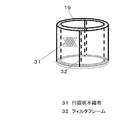
給水タンク17、加湿トレイ18、加湿フィルタ19、送風機20からなる加湿機の構成図を図11に、加湿フィルタ19の構成図を図12に、給水タンク17を自立させながら給水バルブ21を開けるための再生台22の構成図を図13に、再生台22の上に自立させた給水タンク17の構成図を図14に示す。
(Embodiment 2)
In order to open the water supply valve 21 while making the water supply tank 17 self-supporting in FIG. 11, the block diagram of the humidifier which consists of the water supply tank 17, the humidification tray 18, the humidification filter 19, and the air blower 20 is shown in FIG. FIG. 13 shows a configuration diagram of the regeneration stand 22, and FIG. 14 shows a configuration diagram of the water supply tank 17 made independent on the regeneration stand 22.

給水タンク17はタンク蓋23と、タンク蓋23の裏に装着したスケール除去器1を備えている。タンク蓋23の円周部内側にはねじ溝B24が付いていて、同じくねじ溝B24が設けられた給水タンク17本体に被せてねじることで給水タンク17の開け閉めをすることができる。   The water supply tank 17 includes a tank lid 23 and a scale remover 1 attached to the back of the tank lid 23. A screw groove B24 is provided on the inner side of the circumferential portion of the tank lid 23, and the water supply tank 17 can be opened and closed by twisting it over a water supply tank 17 body similarly provided with the screw groove B24.

また、スケール除去器1にはねじ溝C25が設けられており、タンク蓋23の裏側に設けられたねじ溝C25に当ててねじることでタンク蓋23に着脱することができる。スケール除去器1が装着されたタンク蓋23を開け、給水タンク17に水を入れ、タンク蓋23を閉め、給水タンク17を上下にひっくり返し、図11のとおり加湿機に装着する。   Further, the scale remover 1 is provided with a thread groove C25, which can be attached to and detached from the tank cover 23 by twisting against the thread groove C25 provided on the back side of the tank cover 23. The tank lid 23 to which the scale remover 1 is attached is opened, water is poured into the water supply tank 17, the tank lid 23 is closed, the water supply tank 17 is turned upside down, and is attached to the humidifier as shown in FIG.

ここでタンク蓋23に設けられた給水バルブ21はバルブばね26とゴム製の弁27を有し、押さない限りは閉じられているため給水タンク17を上下にひっくり返しても水が漏れない。また、給水タンク17はトレイ支持体29に支えられて加湿機内で自立している。給水タンク17を加湿機に装着後、加湿機に設けられたトレイ突起28が給水バルブ21に設けられたバルブ先端30に接触して給水バルブ21を押し開く。   Here, the water supply valve 21 provided in the tank lid 23 has a valve spring 26 and a rubber valve 27 and is closed unless pushed, so that water does not leak even if the water supply tank 17 is turned upside down. The water supply tank 17 is supported by the tray support 29 and is self-supporting in the humidifier. After mounting the water supply tank 17 on the humidifier, the tray protrusion 28 provided on the humidifier contacts the valve tip 30 provided on the water supply valve 21 to push the water supply valve 21 open.

そしてマリオットのびんの原理によって口ばし37とほぼ同じ位置まで加湿トレイ18に水が供給される。加湿トレイ18に供給された水は、図12に示すような通気性を有する不織布を円筒状に丸めた円筒状不織布31をフィルタフレーム32に納めた加湿フィルタ19に吸い上げられる。   Then, water is supplied to the humidifying tray 18 to the same position as the mouthpiece 37 by the principle of the Marriott bottle. The water supplied to the humidifying tray 18 is sucked up by the humidifying filter 19 in which a cylindrical nonwoven fabric 31 obtained by rolling a nonwoven fabric having air permeability as shown in FIG.

円筒状不織布31に吸い上げられた水は送風機20によって空気吸込み口33から入り円筒状不織布31の中を通り抜ける空気と接触して気化し、水蒸気となる。水蒸気を含んだ空気は通風方向34に沿ってオリフィス35の下流にある送風機20へとスムーズに吸い込まれ、空気吹出し口36から吹き出され、周囲を加湿する。   The water sucked up by the cylindrical nonwoven fabric 31 is vaporized in contact with the air that enters from the air suction port 33 through the cylindrical nonwoven fabric 31 and passes through the cylindrical nonwoven fabric 31. The air containing water vapor is smoothly sucked into the blower 20 downstream of the orifice 35 along the ventilation direction 34 and blown out from the air outlet 36 to humidify the surroundings.

ここで、給水タンク17の水は全てスケール除去器1の外筒2側壁全周に設けられた入口10を通って内筒3側壁全周に設けられた出口12から出て、給水バルブ21を通じて加湿トレイ18へと供給される。この時水は自重による圧力によってスケール除去器1の中を通過し、加湿トレイ18へ供給される。   Here, all the water in the water supply tank 17 passes through the inlet 10 provided on the entire circumference of the outer cylinder 2 side wall of the scale remover 1, exits from the outlet 12 provided on the entire circumference of the inner cylinder 3 side wall, and passes through the water supply valve 21. It is supplied to the humidifying tray 18. At this time, the water passes through the scale remover 1 by the pressure due to its own weight and is supplied to the humidifying tray 18.

そして給水タンク17からなくなった水の体積を埋めるように給水バルブ21から空気孔16を通じて給水タンク17の内部に空気が入る。そしてタンク蓋23に設けられた口ばし37に水面が触れて空気の通り道が塞がれるまで給水タンク17内の水は加湿トレイ18に供給される。加湿トレイ18の水は加湿されて水面が下がったら再度口ばし37に水面が触れるまで給水タンク17から加湿トレイ18に水が供給される。   Then, air enters the water supply tank 17 from the water supply valve 21 through the air hole 16 so as to fill the volume of water that has disappeared from the water supply tank 17. The water in the water supply tank 17 is supplied to the humidifying tray 18 until the water surface touches the mouthpiece 37 provided on the tank lid 23 to block the passage of air. When the water in the humidifying tray 18 is humidified and the water level drops, the water is supplied from the water supply tank 17 to the humidifying tray 18 until the water surface touches the mouth opening 37 again.

給水タンク17内の水はスケール除去器1を通過することで中に含まれていた第2族元素イオンが取り除かれ、その後に加湿トレイ18に供給され、加湿フィルタ19に吸い上げられる。そのため第2族元素イオンが炭酸イオンと結合し、不溶性塩となって加湿トレイ18や加湿フィルタ19にこびりつくことを防ぐことができる。   The water in the water supply tank 17 passes through the scale remover 1 to remove the group 2 element ions contained therein, and then is supplied to the humidifying tray 18 and sucked up by the humidifying filter 19. Therefore, it is possible to prevent the group 2 element ions from being combined with carbonate ions to become insoluble salts and stick to the humidifying tray 18 or the humidifying filter 19.

炭酸カルシウムなどの不溶性塩は一旦こびりつくと剥がすのに大変な労力を必要とする。また、円筒状不織布31の繊維と繊維の間にこびりつき、水の吸い上げを阻害する。そのため加湿機は加湿能力の低下を引き起こすが本実施の形態の加湿機では本発明のスケール除去器1を設けることによってこの問題を解決している。また、スケール除去器1をタンク蓋23の裏に装着して給水タンク17本体の中に納めているためスケール除去器1を設置する場所を省略することができる。その結果、加湿機を小型化することが可能となっている。   Insoluble salts such as calcium carbonate require a lot of labor to remove once they stick. Moreover, it sticks between the fibers of the cylindrical nonwoven fabric 31 and inhibits the water from being sucked up. For this reason, the humidifier causes a decrease in the humidifying ability, but the humidifier according to the present embodiment solves this problem by providing the scale remover 1 of the present invention. Further, since the scale remover 1 is mounted on the back of the tank lid 23 and stored in the main body of the water supply tank 17, a place for installing the scale remover 1 can be omitted. As a result, the humidifier can be reduced in size.

スケール除去器1が捕捉除去できる第2族元素イオンの量には限界があり、限界に達した後は高濃度の、例えば濃度が50g/Lの塩化ナトリウム水溶液をゆっくり通水することで捕捉した第2族元素イオンを放出してナトリウムイオンに置換することができる。   There is a limit to the amount of group 2 element ions that can be captured and removed by the scale remover 1, and after reaching the limit, the ions were captured by slowly passing a high concentration, for example, 50 g / L sodium chloride aqueous solution. Group II element ions can be released and replaced with sodium ions.

第2族元素イオンを再度捕捉除去するためにこのようにしてスケール除去器1を再生することができる。再生に用いた塩化ナトリウム水溶液の中には脱離した第2族元素イオンが大量に含まれているため、加湿機に入れて加湿に用いてはいけない。したがって再生の際にはスケール除去器1を加湿機から取り外して別の場所で行う必要がある。   The scale remover 1 can thus be regenerated in order to capture and remove the Group 2 element ions again. The aqueous sodium chloride solution used for regeneration contains a large amount of desorbed group II element ions, so it should not be used for humidification in a humidifier. Therefore, at the time of regeneration, it is necessary to remove the scale remover 1 from the humidifier and perform it at another place.

ここで図13に示すとおり、再生台22はバルブ先端30を押して給水バルブ21を開けるための再生台突起38が中央に、給水タンク17を支えて自立させるための再生台支持体39を周囲に備えている。そして給水タンク17の中に塩化ナトリウム水溶液を入れ、スケール除去器1を装着したタンク蓋23を閉め、給水タンク17の上下をひっくり返し、洗面所シンクや流し台シンクなど排水可能な場所に置いた再生台22の上に自立させる。   Here, as shown in FIG. 13, the regeneration stand 22 has a regeneration stand projection 38 for pushing the valve tip 30 to open the water supply valve 21 in the center, and a regeneration stand support 39 for supporting the water supply tank 17 so as to be independent. I have. Then, the sodium chloride aqueous solution is put into the water supply tank 17, the tank lid 23 with the scale remover 1 is closed, the top and bottom of the water supply tank 17 are turned upside down, and placed in a drainable place such as a sink sink or sink sink. Stand on the table 22.

再生台22の再生台突起38に押されることによって給水バルブ21は開かれ、給水タンク17の中の塩化ナトリウム水溶液はスケール除去器1に通水されると同時にシンクの排水口へと排水される。また同時に給水バルブ21から空気孔16を通じて空気が給水タンク17に入る。   The water supply valve 21 is opened by being pushed by the regeneration stand projection 38 of the regeneration stand 22, and the aqueous sodium chloride solution in the water supply tank 17 is passed through the scale remover 1 and simultaneously drained into the drain of the sink. . At the same time, air enters the water supply tank 17 from the water supply valve 21 through the air hole 16.

こうして給水タンク17内の塩化ナトリウム水溶液は全てなくなるまでスケール除去器1に通水される。全てが通水し終えたらタンク蓋23を開けて給水タンク17の中やタンク蓋23、スケール除去器1を水ですすぐ。その後、給水タンク17に加湿するための水道水を入れ、タンク蓋23で蓋をし、加湿機にセットする。   In this way, water is passed through the scale remover 1 until the aqueous sodium chloride solution in the water supply tank 17 is completely exhausted. When all the water has passed, the tank lid 23 is opened, and the inside of the water supply tank 17, the tank lid 23, and the scale remover 1 are rinsed with water. Thereafter, tap water for humidification is put into the water supply tank 17, and the tank lid 23 is covered with the water and set in the humidifier.

このように本発明の加湿機は塩化ナトリウム水溶液を入れた給水タンク17にスケール除去器1が装着されたタンク蓋23で蓋をし、その後自再生台の上に静置するだけで手軽にスケール除去器を再生することができる。   As described above, the humidifier of the present invention simply covers the water supply tank 17 containing the sodium chloride aqueous solution with the tank cover 23 to which the scale remover 1 is mounted, and then simply sets the scale remover 1 on the self-regeneration stand to easily scale. The remover can be regenerated.

実施の形態1で示したスケール除去器1を実際に作成し、実施の形態2で示した給水タンク17および加湿トレイ18を用いて第2族元素イオンの除去性能を評価した。   The scale remover 1 shown in the first embodiment was actually made, and the removal performance of the group 2 element ions was evaluated using the water supply tank 17 and the humidifying tray 18 shown in the second embodiment.

試験には塩化カルシウム2水和物1.10g、硫酸マグネシウム7水和物0.63g、塩化ナトリウム0.78gを水に溶かして1リットルにした人工硬水を用いた。この人工硬水はアメリカ硬度(以下硬度)で表すと1000ppmとなる。   In the test, artificial hard water in which 1.10 g of calcium chloride dihydrate, 0.63 g of magnesium sulfate heptahydrate and 0.78 g of sodium chloride were dissolved in water to make 1 liter was used. This artificial hard water is 1000 ppm in terms of American hardness (hereinafter referred to as hardness).

容量3.8Lの給水タンクに人工硬水を入れ、スケール除去器1を固定したタンク蓋23で蓋をした。そして給水タンク17をひっくり返して加湿トレイ18に設置した。人工硬水はスケール除去器1を通過した後に加湿トレイ18へと流れ、貯まる。そして水面がくちばしに達し、通水が止まる。通水が止まった後の加湿トレイ18の水の硬度を測定し、以下の式で第2族元素イオン除去率を求めた。   Artificial hard water was put into a water supply tank having a capacity of 3.8 L, and the scale was removed with a tank lid 23 to which the scale remover 1 was fixed. Then, the water supply tank 17 was turned over and installed in the humidifying tray 18. The artificial hard water flows to the humidifying tray 18 after passing through the scale remover 1 and is stored. And the water surface reaches the beak and the water flow stops. The water hardness of the humidifying tray 18 after the water flow stopped was measured, and the group 2 element ion removal rate was determined by the following equation.

第2族元素イオン除去率(%)=(1−加湿トレイ18の水の硬度/給水タンク17の水の硬度)×100
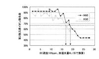
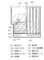
評価に用いたスケール除去器1は2種類で、高さが60mmの「H60」と高さが30mmの「H30」である。両方とも共通して外筒2の内径が64mm、内筒3の外径が28mmであり、外筒2の内周および内筒3の外周にメッシュ材13を設けている。結果を図15に示す。
Group 2 element ion removal rate (%) = (1-water hardness of the humidifying tray 18 / water hardness of the water supply tank 17) × 100
There are two types of scale removers 1 used in the evaluation: “H60” having a height of 60 mm and “H30” having a height of 30 mm. In both cases, the inner diameter of the outer cylinder 2 is 64 mm, the outer diameter of the inner cylinder 3 is 28 mm, and the mesh material 13 is provided on the inner periphery of the outer cylinder 2 and the outer periphery of the inner cylinder 3. The results are shown in FIG.

図15のグラフの縦軸は第2族元素イオン除去率、横軸は使用日数である。ここで使用日数とは、加湿に用いる水道水の硬度を100ppm、1日に使用する水道水の量を4Lとして以下の式で求めた値である。   The vertical axis of the graph of FIG. 15 is the group 2 element ion removal rate, and the horizontal axis is the number of days used. Here, the number of days used is a value obtained by the following formula, assuming that the hardness of tap water used for humidification is 100 ppm and the amount of tap water used for one day is 4L.

使用日数(日)=1000ppm/100ppm×通水した人工硬水の量(L)/4L
この結果、H30はイオン交換樹脂の充填量がH60の1/2であるにも関わらず、第2族元素イオン除去率が67%になるまでの日数で比較するとH30が16.5日、H60が19日となり、H30はH60の0.87倍に相当することがわかった。これは、高さを外筒径の約半分まで低くしたほうが上下のむらなく均一に通水しやすいことを示している。
Number of days used (day) = 1000 ppm / 100 ppm × Amount of artificial hard water passed (L) / 4L
As a result, H30 is 16.5 days compared with the number of days until the Group 2 element ion removal rate becomes 67%, even though the filling amount of ion exchange resin is ½ of H60. Was 19 days, and H30 was found to correspond to 0.87 times H60. This indicates that it is easier to pass water evenly when the height is reduced to about half of the outer cylinder diameter without unevenness in the vertical direction.

また、実施の形態1で説明した、高さ方向においてメッシュ材の目の大きさを、上半分より下半分を細かくする、理由と同様に、水圧の影響を少なくできるため高さは低い方がよく、第2族元素イオンの除去性能をより高くするには高さを外筒径の1/2以下にするとよいといえる。   In addition, the size of the mesh material in the height direction described in the first embodiment is made smaller in the lower half than in the upper half. Well, it can be said that the height should be ½ or less of the outer cylinder diameter in order to further improve the removal performance of the Group 2 element ions.

以上のごとく本発明のスケール除去器はカルシウムイオンやマグネシウムイオンなどの第2族元素イオンが取り除かれた水を長期間、もしくは大量に供給することができ、不溶性塩の発生を防ぐ機器として有用である。また、本発明の加湿機は清潔で洗浄メンテの手間がかからない加湿トレイを提供し、常に高い加湿能力を発揮するため、例えば居住空間の加湿装置として大いに活用が期待できるものである。   As described above, the scale remover of the present invention can supply water from which Group II element ions such as calcium ions and magnesium ions have been removed for a long period or in large quantities, and is useful as a device for preventing the generation of insoluble salts. is there. In addition, the humidifier of the present invention provides a humidifying tray that is clean and does not require much maintenance, and always exhibits a high humidifying capacity. Therefore, it can be expected to be used as a humidifying device in a living space, for example.

1 スケール除去器
2 外筒
3 内筒
4 下面
5 内筒下面複合体
6 イオン交換樹脂
7 上蓋
8 スポンジ体
9 外筒支柱
10 入口
11 内筒支柱
12 出口
13 メッシュ材
14 取水孔
15 通水方向
16 空気孔
17 給水タンク
18 加湿トレイ
19 加湿フィルタ
20 送風機
21 給水バルブ
22 再生台
23 タンク蓋
24 ねじ溝B
25 ねじ溝C
26 バルブばね
27 弁
28 トレイ突起
29 トレイ支持体
30 バルブ先端
31 円筒状不織布
32 フィルタフレーム
33 空気吸込み口
34 通風方向
35 オリフィス
36 空気吹出し口
37 口ばし
38 再生台突起
39 再生台支持体
DESCRIPTION OF SYMBOLS 1 Scale remover 2 Outer cylinder 3 Inner cylinder 4 Lower surface 5 Inner cylinder lower surface composite body 6 Ion exchange resin 7 Upper lid 8 Sponge body 9 Outer cylinder support | pillar 10 Inlet 11 Inner cylinder support | pillar 12 Outlet 13 Mesh material 14 Water intake hole 15 Water flow direction 16 Air hole 17 Water supply tank 18 Humidification tray 19 Humidification filter 20 Blower 21 Water supply valve 22 Regeneration stand 23 Tank lid 24 Screw groove B
25 Thread groove C
26 Valve spring 27 Valve 28 Tray projection 29 Tray support 30 Valve tip 31 Cylindrical non-woven fabric 32 Filter frame 33 Air suction port 34 Ventilation direction 35 Orifice 36 Air blowout port 37 Opening 38 Reproduction stand projection 39 Reproduction stand support

Claims (7)

中心軸と高さを同じくする外筒および内筒と、この外筒および内筒の開口をふさぐ上面、下面からなり、
前記上面の中央部には前記内筒よりも径が小さい空気孔を、
前記下面の中央部には前記内筒よりも径が小さい取水孔を、
前記外筒の側壁には複数の支柱で分割された複数の開口で構成される、スケールを含んだ処理液を流入させる流入口を、
前記内筒の側壁には複数の支柱で分割された複数の開口で構成される、前記処理液を流出させる流出口を有し、
前記外筒と前記内筒の間に粒状のイオン交換樹脂を充填し、前記流入口および前記流出口に前記イオン交換樹脂よりも目の細かいメッシュ材を設けることを特徴とするスケール除去器。
It consists of an outer cylinder and an inner cylinder that have the same height as the central axis, and an upper surface and a lower surface that block the opening of the outer cylinder and the inner cylinder.
An air hole having a diameter smaller than that of the inner cylinder is formed at the center of the upper surface.
A water intake hole having a diameter smaller than that of the inner cylinder is formed at the center of the lower surface.
On the side wall of the outer cylinder, an inflow port configured to flow in a treatment liquid containing a scale, which includes a plurality of openings divided by a plurality of support columns,
On the side wall of the inner cylinder, there is an outlet that is configured by a plurality of openings divided by a plurality of support columns and allows the processing liquid to flow out,
A scale remover, wherein a granular ion exchange resin is filled between the outer cylinder and the inner cylinder, and a mesh material finer than the ion exchange resin is provided at the inlet and the outlet.
内筒の内側にスポンジ体を有することを特徴とする請求項1記載のスケール除去器。 The scale remover according to claim 1, further comprising a sponge body inside the inner cylinder. スポンジ体が親水性を有することを特徴とする請求項2記載のスケール除去器。 The scale remover according to claim 2, wherein the sponge body has hydrophilicity. 高さ方向においてメッシュ材の目の大きさを、上半分より下半分を細かくすることを特徴とする請求項1乃至3いずれかに記載のスケール除去器。 The scale remover according to any one of claims 1 to 3, wherein the size of the mesh material in the height direction is made finer in the lower half than in the upper half. 高さが外筒径の半分以下であることを特徴とする請求項1乃至4いずれかに記載のスケール除去器。 The scale remover according to any one of claims 1 to 4, wherein the height is not more than half of the outer cylinder diameter. 給水バルブが設けられたタンク蓋を備えた給水タンク、および加湿トレイを有し、請求項1乃至5いずれかに記載のスケール除去器をタンク蓋に固定して給水タンク内に設けることを特徴とする加湿機。 A water supply tank having a tank cover provided with a water supply valve, and a humidifying tray, wherein the scale remover according to any one of claims 1 to 5 is fixed to the tank cover and provided in the water supply tank. Humidifier. 給水タンクが自立し、かつ給水バルブに固定し給水バルブを常時開ける再生台を備えることを特徴とする請求項6記載の加湿機。 The humidifier according to claim 6, further comprising a regeneration base in which the water supply tank is self-supporting and is fixed to the water supply valve and always opens the water supply valve.
JP2012163385A 2012-07-24 2012-07-24 Scale removing apparatus and humidifier Pending JP2014018786A (en)

Priority Applications (1)

Application Number Priority Date Filing Date Title
JP2012163385A JP2014018786A (en) 2012-07-24 2012-07-24 Scale removing apparatus and humidifier

Applications Claiming Priority (1)

Application Number Priority Date Filing Date Title
JP2012163385A JP2014018786A (en) 2012-07-24 2012-07-24 Scale removing apparatus and humidifier

Publications (1)

Publication Number Publication Date
JP2014018786A true JP2014018786A (en) 2014-02-03

Family

ID=50194283

Family Applications (1)

Application Number Title Priority Date Filing Date
JP2012163385A Pending JP2014018786A (en) 2012-07-24 2012-07-24 Scale removing apparatus and humidifier

Country Status (1)

Country Link
JP (1) JP2014018786A (en)

Cited By (2)

* Cited by examiner, † Cited by third party
Publication number Priority date Publication date Assignee Title
JP2019152365A (en) * 2018-03-02 2019-09-12 株式会社コロナ Humidifier
CN116143209A (en) * 2023-02-23 2023-05-23 安徽晋煤中能化工股份有限公司 Wastewater treatment device in hydrogen peroxide production process

Similar Documents

Publication Publication Date Title
CN209438317U (en) The automatic gas absorption tower structure for changing absorption path and path being desorbed
KR102046476B1 (en) Humidification apparatus capable of preventing water leak
KR20070057486A (en) A wet air cleaner
JP2014018786A (en) Scale removing apparatus and humidifier
KR101916886B1 (en) Humidifier
KR101196885B1 (en) Waterfall type air cleaner
JP2015059263A (en) Hydrogen-oxygen generator
JP5721800B2 (en) Humidifier filter
JP2012229827A (en) Humidifying device
KR100973184B1 (en) An Oxygen Purification Apparatus
JP2014043989A (en) Scale remover and humidifier
KR20190007772A (en) Air purifier
CN206384889U (en) A kind of water softener salt box and water softener
CN105066291A (en) Stereoscopic desk plant purifier
JP2014006029A (en) A scale remover and humidifier
KR20160069565A (en) humidification type air cleaner
KR101018930B1 (en) Complex type air cleaner attached to ceiling
KR102132114B1 (en) air purifier
KR20140030464A (en) Humidifier
TW201144230A (en) Water purifier
JP5762259B2 (en) Air purifier and air conditioner
KR20090118337A (en) Roof mounting type complex humidifier
KR20150024048A (en) Humidification and humidifier
KR100588259B1 (en) Filtering device of Humidifier
CN210740617U (en) Novel humidifier

Legal Events

Date Code Title Description
A711 Notification of change in applicant

Free format text: JAPANESE INTERMEDIATE CODE: A711

Effective date: 20150312