KR101916886B1 - Humidifier - Google Patents
Humidifier Download PDFInfo
- Publication number
- KR101916886B1 KR101916886B1 KR1020120029404A KR20120029404A KR101916886B1 KR 101916886 B1 KR101916886 B1 KR 101916886B1 KR 1020120029404 A KR1020120029404 A KR 1020120029404A KR 20120029404 A KR20120029404 A KR 20120029404A KR 101916886 B1 KR101916886 B1 KR 101916886B1
- Authority
- KR
- South Korea
- Prior art keywords
- air
- housing
- humidifying filter
- filter
- blowing means
- Prior art date
Links
Images


Classifications
-
- F—MECHANICAL ENGINEERING; LIGHTING; HEATING; WEAPONS; BLASTING
- F24—HEATING; RANGES; VENTILATING
- F24F—AIR-CONDITIONING; AIR-HUMIDIFICATION; VENTILATION; USE OF AIR CURRENTS FOR SCREENING
- F24F6/00—Air-humidification, e.g. cooling by humidification
- F24F6/02—Air-humidification, e.g. cooling by humidification by evaporation of water in the air
- F24F6/04—Air-humidification, e.g. cooling by humidification by evaporation of water in the air using stationary unheated wet elements
-
- F—MECHANICAL ENGINEERING; LIGHTING; HEATING; WEAPONS; BLASTING
- F24—HEATING; RANGES; VENTILATING
- F24F—AIR-CONDITIONING; AIR-HUMIDIFICATION; VENTILATION; USE OF AIR CURRENTS FOR SCREENING
- F24F13/00—Details common to, or for air-conditioning, air-humidification, ventilation or use of air currents for screening
- F24F13/28—Arrangement or mounting of filters
Landscapes
- Engineering & Computer Science (AREA)
- Chemical & Material Sciences (AREA)
- Combustion & Propulsion (AREA)
- Mechanical Engineering (AREA)
- General Engineering & Computer Science (AREA)
- Air Humidification (AREA)
Abstract
가습필터에 흡수된 수분을 효과적으로 가습에 사용할 수 있고, 여러 방향으로 가습된 공기를 토출할 수 있는 가습기가 개시된다.
개시되는 가습기는 공기유입부가 형성된 하우징; 상기 하우징 내부에 장착되는 수조; 하부가 상기 수조에 침지되는 가습필터; 상기 가습필터에 의해 적어도 일부 둘러싸인 압력부여공간; 및 상기 가습필터의 상방에 설치되며, 상기 공기유입부를 통해 흡입한 공기를 상기 압력부여공간으로 토출하는 송풍수단;을 포함하고, 상기 송풍수단에 의해 토출된 공기가 상기 압력부여공간으로 유입되어 유입압력에 의해서 상기 가습필터를 통과하여 가습되며 상기 가습필터의 외측면으로 배출되도록 한다.
이러한 가습기에 의하면, 적어도 일부가 가습필터로 둘러싸인 압력부여공간을 이용하여, 가습필터의 상하부에 흡착된 물을 균일하게 가습에 사용할 수 있는 효과를 얻을 수 있다.A humidifier capable of effectively using the moisture absorbed in the humidifying filter for humidification and capable of discharging humidified air in various directions.
The disclosed humidifier includes a housing having an air inlet formed therein; A water tank mounted inside the housing; A humidification filter in which a lower portion is immersed in the water tank; A pressure applying space at least partially enclosed by the humidifying filter; And a blowing means provided above the humidifying filter for blowing air sucked through the air inlet into the pressure applying space, wherein the air discharged by the blowing means flows into the pressure applying space, And is humidified through the humidifying filter by pressure and discharged to the outer surface of the humidifying filter.
According to such a humidifier, it is possible to obtain the effect that the water adsorbed on the upper and lower portions of the humidifying filter can be uniformly used for humidification by using the pressure imparting space surrounded at least part by the humidifying filter.
Description
본 발명은 가습기에 관한 것으로, 더욱 상세하게는 가습필터에 흡수된 수분을 효과적으로 가습에 사용할 수 있고, 여러 방향으로 가습된 공기를 토출할 수 있는 가습기에 관한 것이다.BACKGROUND OF THE INVENTION 1. Field of the Invention The present invention relates to a humidifier, and more particularly, to a humidifier capable of effectively using humidified water absorbed in a humidifying filter and discharging humidified air in various directions.
일반적으로, 실내의 습도를 높이기 위해 인공적으로 습기를 생성 분무하는 가습기는 습기의 생성 방법이 수조에 저장된 물을 소정 온도로 가열시킴으로써 발생되는 수증기를 실내로 자연 분무시키는 방식인 가열식 가습기와, 수조에 저장된 물을 초음파 진동시켜 미세화된 물 입자를 실내로 분무시키는 방식인 초음파식 가습기와, 가열식 가습방식과 초음파식 가습방식이 동시에 구비된 복합식 가습기로 나뉜다.Generally, a humidifier, which artificially generates and emits moisture to raise the humidity of the room, includes a heating type humidifier in which water vapor generated by heating water stored in a water tank to a predetermined temperature is spontaneously sprayed into the room, An ultrasonic humidifier that emits micronized water particles into the room by ultrasonic vibration of the stored water, and a combined humidifier that simultaneously includes a heating humidification system and an ultrasonic humidification system.
최근에는, 수조에 흡습부재를 침지시킨 후 흡습부재 상부측으로 이동한 물을 송풍에 의하여 기화시키거나, 다수의 디스크의 일부분을 수조에 침지시킨 상태에서 회전시킴으로써 디스크 표면에 부착된 물을 송풍에 의하여 기화시키는 등의 방식을 사용하는 자연식 가습기도 사용되고 있다.In recent years, the water adhering to the surface of the disk is blown by blowing water that has moved to the upper side of the moisture absorbing member after immersing the moisture absorbing member in the water tank, or by rotating part of a large number of disks in a water bath A natural humidifier using a vaporizing method is also used.
도 1은 종래의 가습기의 가습동작을 나타내는 개략도로서, 종래의 가습기는 공기유입구(12)와 공기유출구(14)가 구비된 가습기 하우징(10)과, 공기유입구(12)를 통해 공기를 흡입한 후 흡입한 공기를 공기유출구(14)로 토출할 수 있는 송풍기(20)와, 가습에 사용되는 물이 수용되어 있는 수조(30)와, 상기 수조(30)에 하단부가 침지되어 있는 가습필터(40)를 포함하여 구성될 수 있다.FIG. 1 is a schematic view showing a humidifying operation of a conventional humidifier. The conventional humidifier includes a
여기서, 송풍기(20)는 측면방향으로 공기를 흡입하여 흡입한 공기를 원주방향으로 토출할 수 있으며, 토출되는 공기의 방향을 가이드하는 스크롤 케이싱에 의해 하우징(10)의 상단에 구비된 공기유출구(14)로 공기를 토출할 수 있다.Here, the
또한, 송풍기(20)가 작동되면서 공기유입구(12)를 통해 하우징(10) 내부로 공기가 유입될 수 있고, 공기유입구(12)로부터 송풍기(20)까지의 공기 이동경로에는 가습필터(40)가 배치될 수 있다.Air can be introduced into the
이때, 가습필터(40)에는 수조(30)에서 흡수한 물이 상단부까지 흡착되어 있으며, 송풍기(20)에 의해 유동되는 공기는 가습필터(40)를 통과하며 가습필터(40)에 흡착되어 있는 수분을 통해 가습된다.At this time, the water absorbed in the
이와 같이 가습된 공기는 송풍기(20)에 의해 공기유출구(14)로 토출되어 실내를 가습하게 된다.The humidified air is discharged to the
그러나, 이러한 종래의 가습기에서는 공기가 가습필터(40)를 통과하며 상부로 이동하도록 구성되기 때문에 송풍기(20)에서 먼 쪽이 가까운 쪽에 비해 공기의 유동이 적게 된다.However, in such a conventional humidifier, since the air passes through the
이로 인해, 종래의 가습기에서는 도 1에 도시된 바와 같이 가습필터(40) 중 송풍기(20)에서 먼 부분(즉, 가습필터의 하부)이 송풍기(20)에서 가까운 부분(즉, 가습필터의 상부)보다 가습에 활발하게 활용되지 못하게 된다.1, the portion of the
결과적으로, 종래의 가습기에서는 가습필터(40)가 균형적이며 효율적으로 사용되지 못하는 단점이 있다.As a result, in the conventional humidifier, the
따라서, 가습필터(40)가 균형적이며 효율적으로 사용될 수 있는 가습기의 공기 유로구조가 필요하다.Therefore, there is a need for a structure of the air passage of the humidifier in which the humidifying
본 발명은 상기와 같은 종래 기술의 문제점 중 적어도 일부를 해결하고자 안출된 것으로, 일 측면으로서, 가습필터의 상하부에 흡착된 물을 균일하게 가습에 사용할 수 있는 가습기를 제공하는 것을 목적으로 한다.SUMMARY OF THE INVENTION It is an object of the present invention to provide a humidifier capable of uniformly humidifying water adsorbed on upper and lower portions of a humidifying filter as one aspect of the present invention.
또한, 본 발명은 다른 일 측면으로서, 가습된 공기를 넓은 방향으로 토출할 수 있는 가습기를 제공하는 것을 목적으로 한다.Another object of the present invention is to provide a humidifier capable of discharging humidified air in a wide direction.
또한, 본 발명은 다른 일 측면으로서, 사용자의 선택에 따라 가습기능과 공기청정기능이 택일적 또는 일괄적으로 수행될 수 있는 가습기를 제공하는 것을 목적으로 한다.Another object of the present invention is to provide a humidifier in which a humidifying function and an air purifying function can be selectively or collectively performed according to a user's selection.
상기한 목적 중 적어도 일부를 달성하기 위한 일 측면으로서, 본 발명은 공기유입부가 형성된 하우징, 상기 하우징 내부에 장착되는 수조, 상기 하우징의 일측에 장착되며 상기 수조에 물을 공급하는 물통, 하부가 상기 수조에 침지되는 가습필터, 상기 가습필터에 의해 적어도 일부 둘러싸며, 상기 가습필터의 내측공간을 구성하는 압력부여공간 및 상기 가습필터의 상방에 설치되며, 상기 공기유입부를 통해 흡입한 공기를 상기 압력부여공간으로 토출하며, 상기 압력부여공간으로 유입된 유입압력에 의해서 상기 공기유입부로 유입된 공기가 상기 가습필터를 통과하여 가습되며 상기 가습필터의 외측면으로 배출되는 송풍수단을 포함하고, 상기 하우징은 원통형으로 구비되며, 측면부에 공기유출부가 형성되고, 상기 가습필터는 상기 하우징의 형상에 대응되게 형성되되, 일측이 개방된 측면 개방부가 형성된 관 형상으로 형성되어 단면이 말굽 형태를 형성하고, 상기 측면 개방부는 상기 물통이 밀착되어 닫혀지게 결합되어, 상기 가습필터의 전면에 걸쳐 가습된 공기가 배출되어, 상기 하우징의 둘레의 공기유출부로 가습된 공기가 균일하게 배출되는 가습기를 제공한다.According to one aspect of the present invention, there is provided an air conditioner comprising: a housing having an air inlet formed therein; a water tank mounted inside the housing; a water tank installed at one side of the housing to supply water to the water tank; A humidification filter which is at least partially surrounded by the humidifying filter and which is provided above the humidification filter and constitutes an inner space of the humidifying filter, And a blowing means for blowing air introduced into the air inlet through the humidifying filter to be humidified and discharged to an outer surface of the humidifying filter, An air outlet portion is formed in a side portion, and the humidifying filter is formed in a shape of the housing And the side openings are closed and tightly coupled to each other to form a humidified air over the entire surface of the humidifying filter, And the humidified air is uniformly discharged to the air outlet portion around the housing.
삭제delete
삭제delete
이러한 가습기에서 상기 가습필터는 통기성 필터로 구성될 수 있다.In such a humidifier, the humidifying filter may be composed of a breathable filter.
삭제delete
삭제delete
또한 바람직하게, 상기 송풍수단은 측면에서 공기를 흡입하여 원주방향으로 토출하는 원심형 송풍팬; 및 상기 원심형 송풍팬이 수납되며, 상기 수조방향으로 송풍구가 형성된 스크롤 케이싱;을 포함하여 구성될 수 있다.Preferably, the blowing means includes a centrifugal blower blowing air in the circumferential direction by sucking air from the side; And a scroll casing in which the centrifugal blower fan is accommodated and in which a tuyer is formed in the water tank direction.
또한, 일 실시예에서 상기 공기유입부의 내측에는 공기청정필터가 구비될 수도 있다.Further, in one embodiment, an air purifying filter may be provided inside the air inlet.
한편, 상기 가습기는 상기 공기유입부의 내측에 구비되는 공기청정필터; 및 상기 송풍수단의 상측에 설치되며 상기 공기유입부를 통해 흡입한 공기를 상기 하우징의 상단으로 토출하는 공기청정용 송풍수단;을 더 포함할 수 있다.The humidifier includes an air purifying filter disposed inside the air inlet unit. And air purifying blowing means installed on the upper side of the blowing means and discharging the air sucked through the air inflow portion to the upper end of the housing.
바람직하게, 상기 공기청정용 송풍수단은 측면에서 공기를 흡입하여 원주방향으로 토출하는 원심형 송풍팬; 및 상기 원심형 송풍팬이 수납되며, 상기 하우징의 상단 방향으로 송풍구가 형성된 스크롤 케이싱;을 포함하여 구성될 수 있다.Preferably, the air cleaning blowing means includes a centrifugal blowing fan for sucking air from the side and discharging the air in a circumferential direction; And a scroll casing in which the centrifugal blower fan is accommodated and in which a fan is formed in an upper direction of the housing.
삭제delete
또한 바람직하게, 상기 하우징의 하단부 측면과 상단에는 공기유출부가 형성될 수 있고, 상기 하우징의 하단부 측면에 형성된 공기유출부로는 가습된 공기 또는 정화 및 가습된 공기가 배출될 수 있으며, 상기 하우징의 상단에 형성된 공기유출부로는 정화된 공기가 토출될 수 있다.Preferably, the air outlet portion may be formed at the lower end side and the upper end of the housing, and the humidified air or purified and humidified air may be discharged to the air outlet portion formed at the lower end side face of the housing, The purified air can be discharged to the air outlet portion formed in the air outlet portion.
또한 바람직하게, 상기 송풍수단 측의 공기유입부 및 상기 공기청정용 송풍수단 측의 공기유입부 각각에는 서로 독립적으로 분리가능한 공기청정필터가 구비될 수 있다.Preferably, the air inlet portion on the air blowing means side and the air inlet portion on the air blowing means side for air cleaning may be provided with an air cleaning filter which can be independently detachable from each other.
이러한 구성을 갖는 본 발명의 일 실시예에 의하면, 적어도 일부가 가습필터로 둘러싸인 압력부여공간을 이용하여, 가습필터의 상하부에 흡착된 물을 균일하게 가습에 사용할 수 있는 효과를 얻을 수 있다.According to the embodiment of the present invention having such a configuration, it is possible to obtain the effect that the water adsorbed on the upper and lower portions of the humidifying filter can be uniformly used for humidification by using the pressure imparting space surrounded at least in part by the humidifying filter.
또한, 본 발명의 일 실시예에 의하면, 가습된 공기를 하우징의 다방면으로 배출시킬 수 있는 효과를 얻을 수 있다.According to the embodiment of the present invention, the humidified air can be discharged to the various surfaces of the housing.
또한, 본 발명의 일 실시예에 의하면, 공기청정 전용 송풍수단과 가습용 송풍수단을 별개로 구비하여, 사용자의 선택에 따라 가습기능과 공기청정기능이 택일적 또는 일괄적으로 수행될 수 있는 효과를 얻을 수 있다.In addition, according to the embodiment of the present invention, it is possible to provide the air purifying dedicated blowing means and the humidifying blowing means separately from each other, so that the humidifying function and the air purifying function can be performed selectively or collectively Can be obtained.
도 1은 종래의 가습기의 가습동작을 나타내는 개략도.
도 2는 본 발명의 일 실시예에 의한 가습기의 분해사시도.
도 3은 도 2에 도시된 가습기의 측단면도.
도 4는 도 2에 도시된 가습기의 정단면도.
도 5는 도 2에 도시된 가습기에 형성된 압력부여공간의 평면도.
도 6은 본 발명의 다른 일 실시예에 의한 가습기의 분해사시도.
도 7은 도 6에 도시된 가습기의 측단면도.
도 8은 도 6에 도시된 가습기의 정단면도.1 is a schematic view showing a humidifying operation of a conventional humidifier;
2 is an exploded perspective view of a humidifier according to an embodiment of the present invention;
3 is a side cross-sectional view of the humidifier shown in Fig.
Fig. 4 is a front sectional view of the humidifier shown in Fig. 2; Fig.
5 is a plan view of a pressure applying space formed in the humidifier shown in Fig. 2;
6 is an exploded perspective view of a humidifier according to another embodiment of the present invention.
7 is a side cross-sectional view of the humidifier shown in Fig.
8 is a front sectional view of the humidifier shown in Fig.
본 명세서에서 사용한 용어는 단지 특정한 실시예를 설명하기 위해 사용된 것으로, 본 발명을 한정하려는 의도가 아니다. 또한, 본 명세서에서 단수의 표현은 문맥상 명백하게 다르게 뜻하지 않는 한, 복수의 표현을 포함한다. The terminology used herein is for the purpose of describing particular embodiments only and is not intended to be limiting of the invention. Furthermore, the singular forms "a", "an," and "the" include plural referents unless the context clearly dictates otherwise.
그리고, 본 명세서에서, "포함하다", "구비하다", "가지다(갖다)" 등의 용어는 명세서상에 기재된 특징, 숫자, 단계, 동작, 구성요소, 부품 또는 이들을 조합한 것이 존재함을 지정하려는 것이지, 하나 또는 그 이상의 다른 특징들이나 숫자, 단계, 동작, 구성요소, 부품 또는 이들을 조합한 것들의 존재 또는 부가 가능성을 미리 배제하지 않는 것으로 이해되어야 한다.In this specification, terms such as " comprise ", " comprise ", and " have "mean that there exist features, numbers, steps, operations, elements, parts, And should not be construed to preclude the presence or addition of one or more other features, numbers, steps, operations, components, parts, or combinations thereof.
이하, 첨부한 도면을 참고로 하여 본 발명의 바람직한 실시예에 대하여 설명한다.
Hereinafter, preferred embodiments of the present invention will be described with reference to the accompanying drawings.
먼저, 도 2 내지 도 5를 참조하여 본 발명의 일 실시예에 의한 가습기에 대해서 살펴본다. 여기서, 도 2는 본 발명의 일 실시예에 의한 가습기의 분해 사시도이고, 도 3은 측단면도, 도 4는 정단면도, 도 5는 압력공간부의 평면도이다.
First, a humidifier according to an embodiment of the present invention will be described with reference to FIGS. 2 to 5. FIG. Here, FIG. 2 is an exploded perspective view of a humidifier according to an embodiment of the present invention, FIG. 3 is a side sectional view, FIG. 4 is a front sectional view, and FIG. 5 is a plan view of a pressure space portion.
도 2 내지 도 5에 도시된 바와 같이, 본 발명의 일 실시예에 의한 가습기(100)는 하우징(110), 수조(120), 가습필터(130), 압력부여공간(600) 및 송풍수단(140)을 포함하고, 상기 수조(120)에 물을 공급할 수 있는 물통(150) 및 공기를 정화할 수 있는 공기청정필터(160)가 추가로 포함될 수 있다.2 to 5, a
상기 하우징(110)은 본 발명의 일 실시예에 의한 가습기(100)의 외형을 구성하며, 이러한 하우징(110)에는 외부의 공기가 하우징(110) 내부로 유입될 수 있는 공기유입부(112)와 하우징(110) 내부의 공기가 외부로 유출될 수 있는 공기유출부(114)가 형성될 수 있다.The
일 실시예서, 하우징(110)은 도 2에 도시된 바와 같이 원통형으로 구성될 수 있으며, 원통형 하우징(110)의 측면부에 공기유입부(112)와 공기유출부(114)가 상하로 구비될 수 있다.In an embodiment, the
한편, 상기 수조(120)는 하우징(110) 내부에 장착되며, 수조(120)에는 가습에 사용되는 물이 수용되어 있다. 일 실시예에서, 수조(120)는 하우징(110)의 하단부에 장착될 수 있으며 하우징(110)의 단면형태에 대응하는 원통형으로 구성될 수 있다. 다만, 수조(120)의 형태가 이에 한정되지 않고 물을 수용하고 하우징(110)에 장착가능한 다양한 형태를 가질 수 있음은 자명하다.Meanwhile, the
한편, 상기 가습필터(130)는 하부가 수조(120)에 침지되도록 장착될 수 있으며, 침지된 상태에서 수조(120)에 수용되어 있는 물을 흡착할 수 있다. 일 실시예에서, 가습필터(130)는 공기가 통과하면서 흡착된 물이 기화될 수 있는 통기성 필터로 구성될 수 있다.Meanwhile, the
한편, 상기 압력부여공간(600)은 가습필터(130)에 의해 적어도 일부 둘러싸여서 형성될 수 있다. 다시 말해, 압력부여공간(600)을 구성하는 측벽의 적어도 일부는 가습필터(130)로 구성될 수 있다.Meanwhile, the
이때, 본 발명의 일 실시예에 의한 가습기(100)에서는 압력부여공간(600)을 구성하는 측벽이 가습필터(130)로 구성되는 부분이 많을수록 기화시킬 수 있는 물의 양이 많으므로 가습기(100)의 가습율이 높을 수 있다.At this time, in the
이에 따라, 가습필터(130)는 관 형상 또는 일측이 개방된 관 형상으로 구성될 수 있으며, 일 실시예에서는 도 2에 도시된 바와 같이 일측이 개방된 개단면 관 형상(예를 들면, 말굽형태)으로 구성될 수 있다.Accordingly, the
이때, 가습필터(130)의 내측공간은 압력부여공간(600)을 구성할 수 있다. At this time, the inner space of the
여기서, 압력부여공간(600)의 측면 개방부를 제외한 나머지 측면부는 모두 가습필터(130)로 구성될 수 있게 된다. 또한, 압력부여공간(600)의 측면 개방부는 하우징(110), 수조(120) 또는 물통(150)과 같은 독립된 부재에 의해 닫히도록 구성될 수도 있다.Here, all the remaining side portions of the
한편, 이러한 가습필터(130)의 형상은 상술한 바와 같이 일측이 개방된 형상에 한정되는 것은 아니며, 원통형으로 구성될 수도 있다. 여기서, 상기 가습필터(130)가 원통형으로 구성되는 경우에는 가습필터(130)의 전체 둘레에 걸쳐 가습된 공기가 배출되는 것도 가능하다.Meanwhile, the shape of the
한편, 상기 송풍수단(140)은 가습필터(130)의 상방에 설치될 수 있으며, 공기유입부(112)를 통해 흡입한 공기를 압력부여공간(600)으로 토출할 수 있도록 구성될 수 있다.The air blowing means 140 may be installed above the
이러한 송풍수단(140)은 흡입한 공기를 압력부여공간(600)으로 토출하는 동작을 수행할 수 있는 장치라면 본 발명의 일 실시예에 의한 가습기(100)에 적용가능하므로, 특별한 형태나 기능으로 한정되지 않고 공지의 다양한 송풍장치로 구성될 수 있다.Since the air blowing means 140 can be applied to the
다만, 도 2에 도시된 본 발명의 일 실시예에서는 하우징(110)의 측면에 공기유입부(112)가 형성될 수 있으므로, 바람직하게, 송풍수단(140)은 측면에서 공기를 흡입하여 원주방향으로 토출하는 원심형 송풍팬(142) 및 상기 원심형 송풍팬(142)이 수납되며 수조(120)방향으로 송풍구가 형성된 스크롤 케이싱(144)을 포함하여 구성될 수 있다.2, the
또한, 도 6 내지 도 8을 참조하여 후술할 본 발명의 다른 일 실시예에 의한 가습기(100')에서는 두 개의 송풍수단(140.170)이 상하로 구비되고, 두 개의 송풍수단(140,170) 각각은 흡입한 공기를 상방과 하방으로 토출하도록 구성되므로, 이 경우에도 송풍수단(140)은 상술한 바와 같이 하우징(110)의 측면에서 공기를 흡입할 수 있도록 원심형 송풍팬(142) 및 스크롤 케이싱(144)을 포함하여 구성되는 것이 바람직하다.In the humidifier 100 'according to another embodiment of the present invention, which will be described later with reference to FIGS. 6 to 8, two blowing means 140.170 are provided at the top and bottom, and each of the two blowing means 140, The
한편, 본 발명의 일 실시예에 의한 가습기(100)에서, 송풍수단(140)에 의해 토출된 공기는 압력부여공간(600)으로 유입될 수 있다.Meanwhile, in the
이와 같이, 압력부여공간(600)으로 유입된 공기는 압력부여공간(600)에 일시적으로 수용될 수 있고, 송풍수단(140)은 지속적으로 압력부여공간(600)에 공기를 토출한다.Thus, the air introduced into the
이로 인해, 상기 압력부여공간(600)에는 기압이 상승할 수 있으며, 압력부여공간(600)에 수용된 공기는 송풍수단(140)에 의해 지속적으로 압력부여공간(600)으로 유입되는 공기의 유입압력에 의해서 가습필터(130)를 통과하여 이동하게 된다.Accordingly, the air pressure in the
이때, 가습필터(130) 전체에는 거의 동일한 압력이 부여될 수 있게 된다. At this time, substantially the same pressure can be applied to the
또한, 이동하는 공기는 가습필터(130)를 통과하며 가습된 후 가습필터(130)의 외측면으로 배출될 수 있다. 또한, 배출된 공기는 하우징(110)에 형성된 공기유출부(114)를 통해 외부로 배출될 수 있게 된다.Further, the moving air can be humidified through the
여기서, 하우징(110)에 형성된 공기유출부(114)는 가습필터(130)의 외측면 형상에 대응되도록 형성될 수 있는데, 이러한 가습필터(130)의 외측면 형상은 가습필터(130)의 높이를 포함하므로, 일 실시예에서 공기유출부(114)는 가습필터(130)를 통과한 공기가 수평방향으로 이동하여 배출될 수 있도록 하우징(110)의 하단부에 가습필터(130)의 높이에 대응하는 높이로 구성되는 것이 바람직하다.The
이와 같은 본 발명의 일 실시예에 의한 가습기(100)에 의하면, 송풍수단(140)에 의해 토출된 공기가 압력부여공간(600)에 수용된 후 유입압력에 의해 가습필터(130)를 통과하므로, 가습필터(130)의 상단부터 하단부까지 전체에 걸쳐 균일하게 공기유동이 가능할 수 있고, 이를 통해 가습필터(130)의 상단뿐만 아니라 하단부에 흡착되어 있는 물도 효과적으로 가습에 사용할 수 있게 된다.According to the
또한, 본 발명의 일 실시예에 의한 가습기(100)에 의하면, 도 5에 도시된 바와 같이 가습필터(130)의 전면에 걸쳐 가습된 공기가 배출될 수 있으므로, 가습기(100)의 둘레를 따라 다양한 방향으로 가습된 공기가 균일하게 배출될 수 있게 된다.5, since humidified air can be exhausted over the entire surface of the
한편, 일 실시예에서 하우징(110)의 일측에는 수조(120)에 물을 공급할 수 있는 물통(150)이 장착될 수 있는데, 상기 물통(150)은 하우징(110)의 일측에 형성된 물통 장착부(116)에 삽입장착될 수 있으며, 수조(120)의 전단에 구비된 물통 결합부(122)에 결합될 수 있다.In one embodiment, a
또한, 일 실시예에서 물통(150)은 가습필터(130)의 측면 개방부에 밀착하도록 구성될 수 있으며, 이로써, 상기 압력부여공간(600)은 가습필터(130)와 물통(150)의 외측면으로 둘러싸여 형성될 수 있다.The
이러한 구성은 본 발명의 일 실시예에 의한 가습기(100)의 소형화를 구현할 수 있는 일 실시예에 불과하므로, 물통(150)의 장착구조가 상기와 같이 물통(150)이 가습필터(130)에 밀착하도록 구성되는 것에 한정되지 않고 다양한 구조를 가질 수 있음은 자명하다. 예를 들면, 가습필터(130)의 개방된 일측을 하우징(110) 또는 수조(120)로 폐쇄하여 압력부여공간(600)을 형성할 수도 있다.Since the mounting structure of the
한편, 상기 공기청정필터(160)는 송풍수단(140)의 작동에 의해 공기유입부(112)로 유입되는 공기가 정화될 수 있도록 공기유입부(112)의 내측에 구비될 수 있다. 다시 말해, 본 발명의 일 실시예에 의한 가습기(100)는 공기청정필터(160)를 통해 공기를 정화할 수 있고, 가습필터(130)를 통해 정화된 공기를 가습시킬 수 있는 가습공기청정기로 구성될 수도 있다.
The
다음으로, 도 6 내지 도 8을 참조하여 본 발명의 다른 일 실시예에 의한 가습기에 대해서 살펴본다. 여기서, 도 6은 본 발명의 다른 일 실시예에 의한 가습기의 분해사시도이고, 도 7은 측단면도, 도 8은 정단면도이다.Next, a humidifier according to another embodiment of the present invention will be described with reference to FIGS. 6 to 8. FIG. Here, FIG. 6 is an exploded perspective view of a humidifier according to another embodiment of the present invention, FIG. 7 is a side sectional view, and FIG. 8 is a front sectional view.
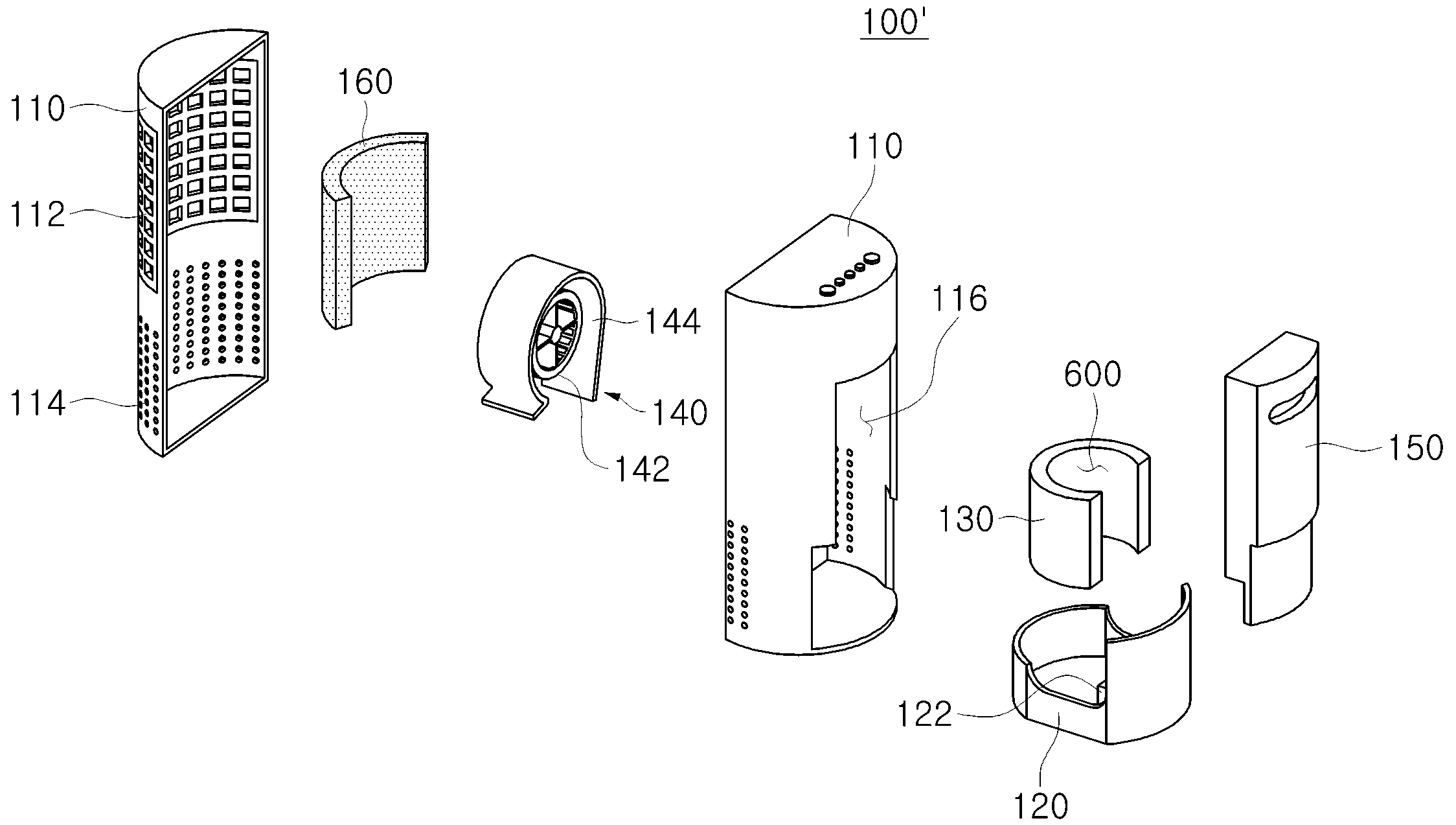
도 6 내지 도 8에 도시된 바와 같이, 본 발명의 다른 일 실시예에 의한 가습기(100')는 도 2 내지 도 5를 참조하여 설명한 본 발명의 일 실시예에 의한 가습기(100)에 공기청정필터(160) 및 공기청정용 송풍수단(170)이 추가로 포함된 구성으로 이루어질 수 있다.6 to 8, the humidifier 100 'according to another embodiment of the present invention includes the
즉, 본 발명의 다른 일 실시예에 의한 가습기(100')에 포함되는 수조(120), 가습필터(130), 압력부여공간(600), 송풍수단(140) 및 물통(150)은 도 2 내지 도 5를 참조하여 상술한 본 발명의 일 실시예에 의한 가습기(100)에 포함된 구성과 실질적으로 동일하다. That is, the
따라서, 상기 수조(120), 가습필터(130), 압력부여공간(600), 송풍수단(140) 및 물통(150)에 대한 설명은 생략하도록 한다.Therefore, the description of the
한편, 상기 공기청정필터(160)는 하우징(110)에 형성된 공기유입부(112)의 내측에 구비되어 유입되는 공기를 정화시킬 수 있다.The
또한, 상기 공기청정용 송풍수단(170)은 도 6 내지 도 8에 도시된 바와 같이 상기 송풍수단(140)의 상측에 설치될 수 있으며, 공기유입부(112)를 통해 흡입한 공기를 하우징(110)의 상단으로 토출하도록 구성될 수 있다.6 to 8, the
이와 같이 송풍수단(140)과 공기청정용 송풍수단(170)이 상하로 설치되기 위해, 다른 일 실시예에서의 하우징(110)은 도 2 내지 도 4에 도시된 일 실시예에서의 하우징(110)보다 길게 구성될 수 있다. In order to install the blowing means 140 and the blowing means 170 for air cleaning up and down as described above, the
또한, 공기유입부(112)는 도 2 내지 도 4에 도시된 공기유입부(112)와 마찬가지로 하우징(110)의 측면에 형성되되, 상하로 배치된 송풍수단(140)과 공기청정용 송풍수단(170)을 포괄할 수 있도록 상하로 길게 형성될 수 있다.The
한편, 이와 같이 상하로 길게 형성된 공기유입부(112) 중에서 송풍수단(140) 측의 공기유입부(112) 및 공기청정용 송풍수단(170) 측의 공기유입부(112) 각각에는 서로 독립적으로 분리가능한 하측 공기청정필터(160a) 및 상측 공기청정필터(160b)가 구비될 수 있다. 다만, 이에 한정되는 것은 아니며 공기유입부(112) 전체에 일체형의 공기청정필터(160)가 구비될 수도 있다.The
한편, 다른 일 실시예에서 공기청정용 송풍수단(170)은 상기 송풍수단(140)과 마찬가지로 측면에서 공기를 흡입하여 원주방향으로 토출하는 원심형 송풍팬(172)과 원심형 송풍팬(172)이 수납되는 스크롤 케이싱(174)을 포함하여 구성될 수 있다. In another embodiment, the air cleaning blowing means 170 includes a
다만, 송풍수단(140)의 스크롤 케이싱(144)과 달리, 공기청정용 송풍수단(170)의 스크롤 케이싱(174)은 원심형 송풍팬(172)이 토출하는 공기가 하우징(110)의 상단 방향으로 토출될 수 있도록 송풍구가 상향으로 형성될 수 있다.Unlike the
또한, 하우징(110)의 하단부 측면에는 가습필터(130)를 통과한 공기가 배출될 수 있는 하측 공기유출부(114a)가 형성될 수 있으며, 하우징(110)의 상단에는 공기청정용 송풍수단(170)이 토출하는 공기가 하우징(110)의 외부로 토출될 수 있는 상측 공기유출부(114b)가 추가적으로 형성될 수 있다.A
이를 통해, 하측 공기유출부(114a)로는 가습만 된 공기 또는 정화 및 가습된 공기가 배출될 수 있고, 상측 공기유출부(114b)로는 정화된 공기가 토출될 수 있다.As a result, humidified air or purified and humidified air can be discharged to the lower
여기서, 하측 공기유출부(114a)로 가습만 된 공기가 배출되도록 하기 위해서는 하측 공기청정필터(160a)를 제거함으로써 가능하고, 정화 및 가습된 공기가 배출되도록 하기 위해서는 공기유입부(112)에 하측 공기청정필터(160a)를 장착함으로써 가능하다.In order to discharge the humidified air to the
이와 같은 본 발명의 다른 일 실시예에 의한 가습기(100)는 공기청정수단과 가습수단을 일체로 포함하여, 상부로 정화된 공기를 토출할 수 있고, 하부로 가습된 공기를 배출할 수 있게 된다.According to another embodiment of the present invention, the
또한, 하측 공기청정필터(160a)를 필요에 따라 선택적으로 장착할 수 있어, 하우징(110)의 하부로 가습 및 정화된 공기를 배출할 수도 있다.
In addition, the lower
본 발명은 특정한 실시예에 관하여 도시하고 설명하였지만, 당업계에서 통상의 지식을 가진 자라면 이하의 특허청구범위에 기재된 본 발명의 사상 및 영역을 벗어나지 않는 범위 내에서 본 발명을 다양하게 수정 및 변경시킬 수 있음을 밝혀두고자 한다.While the present invention has been particularly shown and described with reference to particular embodiments thereof, it is evident that many alternatives, modifications and variations will be apparent to those skilled in the art without departing from the spirit and scope of the invention as defined by the following claims I would like to make it clear.
100, 100' : 가습기
110 : 하우징 112 : 공기유입부
114 : 공기유출부 120 : 수조
130 : 가습필터 140 : 송풍수단
142, 172 : 원심형 송풍팬 144, 174 : 스크롤 케이싱
150 : 물통 160 : 공기청정필터
170 : 공기청정용 송풍수단 600 : 압력부여공간100, 100 ': humidifier
110: housing 112: air inlet
114: air outlet part 120: water tank
130: Humidification filter 140: Ventilation means
142, 172:
150: Water bottle 160: Air cleaning filter
170: air cleaning blowing means 600: pressure applying space
Claims (13)
상기 하우징 내부에 장착되는 수조;
상기 하우징의 일측에 장착되며 상기 수조에 물을 공급하는 물통;
하부가 상기 수조에 침지되는 가습필터;
상기 가습필터에 의해 적어도 일부 둘러싸며, 상기 가습필터의 내측공간을 구성하는 압력부여공간; 및
상기 가습필터의 상방에 설치되며, 상기 공기유입부를 통해 흡입한 공기를 상기 압력부여공간으로 토출하며, 상기 압력부여공간으로 유입된 유입압력에 의해서 상기 공기유입부로 유입된 공기가 상기 가습필터를 통과하여 가습되며 상기 가습필터의 외측면으로 배출되는 송풍수단;을 포함하고,
상기 하우징은 원통형으로 구비되며, 측면부에 공기유출부가 형성되고,
상기 가습필터는 상기 하우징의 형상에 대응되게 형성되되, 일측이 개방된 측면 개방부가 형성된 관 형상으로 형성되어 단면이 말굽 형태를 형성하고, 상기 측면 개방부는 상기 물통이 밀착되어 닫혀지게 결합되어,
상기 가습필터의 전면에 걸쳐 가습된 공기가 배출되어, 상기 하우징의 둘레의 공기유출부로 가습된 공기가 균일하게 배출되는 가습기.A housing having an air inlet;
A water tank mounted inside the housing;
A water bottle mounted on one side of the housing and supplying water to the water tank;
A humidification filter in which a lower portion is immersed in the water tank;
A pressure applying space at least partially surrounded by the humidifying filter and constituting an inner space of the humidifying filter; And
The air introduced into the air introducing portion by the inflow pressure flowing into the pressure applying space passes through the humidifying filter, and the air introduced into the air introducing portion passes through the humidifying filter And a blowing means which is humidified and discharged to an outer surface of the humidifying filter,
The housing has a cylindrical shape, an air outlet is formed in a side portion,
The humidifying filter is formed in a shape corresponding to the shape of the housing and is formed into a tubular shape having a side opening portion opened at one side thereof to form a horseshoe shape and the side opening portion is in close contact with the water container,
Wherein the humidifying air is discharged through the entire surface of the humidifying filter, and the humidified air is uniformly discharged to the air outlet portion around the housing.
상기 가습필터는 통기성 필터로 구성된 것을 특징으로 하는 가습기.The method according to claim 1,
Wherein the humidifying filter comprises a breathable filter.
상기 송풍수단은,
측면에서 공기를 흡입하여 원주방향으로 토출하는 원심형 송풍팬; 및
상기 원심형 송풍팬이 수납되며, 상기 수조방향으로 송풍구가 형성된 스크롤 케이싱;을 포함하여 구성되는 것을 특징으로 하는 가습기.The method according to claim 1,
The blowing means,
A centrifugal air blowing fan for sucking air from the side and discharging the air in a circumferential direction; And
And a scroll casing in which the centrifugal blower fan is accommodated and in which a blowing port is formed in the direction of the water tub.
상기 공기유입부의 내측에는 공기청정필터가 구비된 것을 특징으로 하는 가습기.The method according to any one of claims 1, 4, and 7,
And an air cleaning filter is provided inside the air inlet.
상기 공기유입부의 내측에 구비되는 공기청정필터; 및
상기 송풍수단의 상측에 설치되며 상기 공기유입부를 통해 흡입한 공기를 상기 하우징의 상단으로 토출하는 공기청정용 송풍수단;을 더 포함하는 것을 특징으로 하는 가습기.The method according to any one of claims 1, 4, and 7,
An air purifying filter provided inside the air inlet; And
Further comprising air blowing means for blowing air sucked through the air inflow portion to an upper end of the housing, the air blowing means being disposed above the blowing means.
상기 공기청정용 송풍수단은,
측면에서 공기를 흡입하여 원주방향으로 토출하는 원심형 송풍팬; 및
상기 원심형 송풍팬이 수납되며, 상기 하우징의 상단 방향으로 송풍구가 형성된 스크롤 케이싱;을 포함하여 구성되는 것을 특징으로 하는 가습기.10. The method of claim 9,
Wherein the air cleaning blowing means comprises:
A centrifugal air blowing fan for sucking air from the side and discharging the air in a circumferential direction; And
And a scroll casing in which the centrifugal blower fan is housed and in which a blowing port is formed in an upper direction of the housing.
상기 하우징의 하단부 측면과 상단에는 공기유출부가 형성되고,
상기 하우징의 하단부 측면에 형성된 공기유출부로는 가습된 공기 또는 정화 및 가습된 공기가 배출되며, 상기 하우징의 상단에 형성된 공기유출부로는 정화된 공기가 토출되는 것을 특징으로 하는 가습기.11. The method of claim 10,
An air outflow portion is formed on a lower end side surface and an upper end of the housing,
Wherein humidified air or purified and humidified air is discharged through an air outlet formed in a lower end side surface of the housing, and purified air is discharged through an air outlet formed at an upper end of the housing.
상기 송풍수단 측의 공기유입부 및 상기 공기청정용 송풍수단 측의 공기유입부 각각에는 서로 독립적으로 분리가능한 공기청정필터가 구비되는 것을 특징으로 하는 가습기.10. The method of claim 9,
Wherein an air inflow portion on the air blowing means side and an air inflow portion on the air blowing air blowing means side are provided with an air cleaning filter which can be independently separated from each other.
Priority Applications (2)
| Application Number | Priority Date | Filing Date | Title |
|---|---|---|---|
| KR1020120029404A KR101916886B1 (en) | 2012-03-22 | 2012-03-22 | Humidifier |
| PCT/KR2013/001958 WO2013141513A1 (en) | 2012-03-22 | 2013-03-12 | Humidifier |
Applications Claiming Priority (1)
| Application Number | Priority Date | Filing Date | Title |
|---|---|---|---|
| KR1020120029404A KR101916886B1 (en) | 2012-03-22 | 2012-03-22 | Humidifier |
Publications (2)
| Publication Number | Publication Date |
|---|---|
| KR20130107535A KR20130107535A (en) | 2013-10-02 |
| KR101916886B1 true KR101916886B1 (en) | 2018-11-08 |
Family
ID=49222922
Family Applications (1)
| Application Number | Title | Priority Date | Filing Date |
|---|---|---|---|
| KR1020120029404A KR101916886B1 (en) | 2012-03-22 | 2012-03-22 | Humidifier |
Country Status (2)
| Country | Link |
|---|---|
| KR (1) | KR101916886B1 (en) |
| WO (1) | WO2013141513A1 (en) |
Families Citing this family (6)
| Publication number | Priority date | Publication date | Assignee | Title |
|---|---|---|---|---|
| KR102206325B1 (en) | 2013-12-30 | 2021-01-22 | 코웨이 주식회사 | Humidifier |
| CN104329733B (en) | 2014-07-03 | 2017-11-07 | 青岛海尔空调器有限总公司 | A kind of purifier and air treatment system |
| CN104315644B (en) | 2014-09-18 | 2017-06-13 | 青岛海尔空调器有限总公司 | A kind of humidification device and air treatment system |
| KR101542123B1 (en) * | 2014-12-31 | 2015-08-05 | 엘지전자 주식회사 | Discharging unit and Air conditioner having the same |
| CN105180298A (en) * | 2015-07-23 | 2015-12-23 | 宁波巨凰暖通设备有限公司 | Air purifier with stationary stream stereoscopic air duct |
| CN111854001A (en) * | 2020-08-18 | 2020-10-30 | 北京智米科技有限公司 | Purifying humidifier |
Citations (3)
| Publication number | Priority date | Publication date | Assignee | Title |
|---|---|---|---|---|
| KR100625490B1 (en) * | 2003-12-24 | 2006-09-20 | 삼성전자주식회사 | Humidifying apparatus and air conditioner |
| JP2010019445A (en) * | 2008-07-08 | 2010-01-28 | Sharp Corp | Humidifier |
| JP5056089B2 (en) * | 2007-03-15 | 2012-10-24 | パナソニック株式会社 | Humidifier |
Family Cites Families (3)
| Publication number | Priority date | Publication date | Assignee | Title |
|---|---|---|---|---|
| JP2001336790A (en) * | 2000-05-26 | 2001-12-07 | Hitachi Hometec Ltd | Humidifier |
| JP4862705B2 (en) * | 2007-03-15 | 2012-01-25 | パナソニック株式会社 | Humidifier |
| JP5145853B2 (en) * | 2007-10-16 | 2013-02-20 | パナソニック株式会社 | Humidifier |
-
2012
- 2012-03-22 KR KR1020120029404A patent/KR101916886B1/en active IP Right Grant
-
2013
- 2013-03-12 WO PCT/KR2013/001958 patent/WO2013141513A1/en active Application Filing
Patent Citations (3)
| Publication number | Priority date | Publication date | Assignee | Title |
|---|---|---|---|---|
| KR100625490B1 (en) * | 2003-12-24 | 2006-09-20 | 삼성전자주식회사 | Humidifying apparatus and air conditioner |
| JP5056089B2 (en) * | 2007-03-15 | 2012-10-24 | パナソニック株式会社 | Humidifier |
| JP2010019445A (en) * | 2008-07-08 | 2010-01-28 | Sharp Corp | Humidifier |
Also Published As
| Publication number | Publication date |
|---|---|
| KR20130107535A (en) | 2013-10-02 |
| WO2013141513A1 (en) | 2013-09-26 |
Similar Documents
| Publication | Publication Date | Title |
|---|---|---|
| KR101916886B1 (en) | Humidifier | |
| JP5228319B2 (en) | Air cleaner | |
| JP4008905B2 (en) | Ventilation air cleaner | |
| KR20170051174A (en) | apparatus for both humidification and air cleaning | |
| KR102560978B1 (en) | Air cleaner with humidification | |
| KR20120076284A (en) | Humidification apparatus | |
| JP6272188B2 (en) | Ultrasonic humidifier | |
| KR20120113027A (en) | Humidification filter and humidification apparatus provided therewith | |
| KR102361033B1 (en) | Air washer | |
| KR101817092B1 (en) | Air cleaner | |
| KR20190001334A (en) | Humidification air purifier that can perform both one of humidification function and air cleaning function | |
| KR101856979B1 (en) | Air cleaner | |
| JP5609230B2 (en) | Air purifier with humidification function | |
| KR101669644B1 (en) | Humidifier combined an air cleaner | |
| JP6487298B2 (en) | Toilet deodorizer | |
| JP5150179B2 (en) | Air cleaner | |
| KR20120113028A (en) | Humidification apparatus | |
| JP6179471B2 (en) | Air cleaner | |
| KR200468188Y1 (en) | Humidifying device | |
| KR101403010B1 (en) | Apparatus for humidification and dehumidification | |
| JP2012068005A (en) | Humidification air cleaner | |
| KR20170077644A (en) | Humidifier | |
| JP2014190607A (en) | Humidification unit, humidifier using humidification unit, and humidifier-air cleaner using humidification unit | |
| KR102458899B1 (en) | Natural Air Purifier with Humidification | |
| KR20150146314A (en) | Humidifier |
Legal Events
| Date | Code | Title | Description |
|---|---|---|---|
| A201 | Request for examination | ||
| E902 | Notification of reason for refusal | ||
| E701 | Decision to grant or registration of patent right |