JP2014018061A - Foreign substance sensing device and method in radio electric power transmission system - Google Patents
Foreign substance sensing device and method in radio electric power transmission system Download PDFInfo
- Publication number
- JP2014018061A JP2014018061A JP2013142642A JP2013142642A JP2014018061A JP 2014018061 A JP2014018061 A JP 2014018061A JP 2013142642 A JP2013142642 A JP 2013142642A JP 2013142642 A JP2013142642 A JP 2013142642A JP 2014018061 A JP2014018061 A JP 2014018061A
- Authority
- JP
- Japan
- Prior art keywords
- power
- wireless power
- wireless
- measurement result
- received
- Prior art date
- Legal status (The legal status is an assumption and is not a legal conclusion. Google has not performed a legal analysis and makes no representation as to the accuracy of the status listed.)
- Granted
Links
- 230000005540 biological transmission Effects 0.000 title claims abstract description 133
- 238000000034 method Methods 0.000 title claims abstract description 43
- 239000000126 substance Substances 0.000 title abstract 6
- 238000005259 measurement Methods 0.000 claims abstract description 197
- 238000001514 detection method Methods 0.000 description 23
- 230000003071 parasitic effect Effects 0.000 description 12
- 230000006698 induction Effects 0.000 description 10
- 230000001939 inductive effect Effects 0.000 description 8
- 230000005672 electromagnetic field Effects 0.000 description 6
- 230000020169 heat generation Effects 0.000 description 6
- 230000008878 coupling Effects 0.000 description 3
- 238000010168 coupling process Methods 0.000 description 3
- 238000005859 coupling reaction Methods 0.000 description 3
- RYGMFSIKBFXOCR-UHFFFAOYSA-N Copper Chemical compound [Cu] RYGMFSIKBFXOCR-UHFFFAOYSA-N 0.000 description 2
- 230000015572 biosynthetic process Effects 0.000 description 2
- 230000008859 change Effects 0.000 description 2
- 230000006854 communication Effects 0.000 description 2
- 238000004891 communication Methods 0.000 description 2
- 238000010835 comparative analysis Methods 0.000 description 2
- 230000009977 dual effect Effects 0.000 description 2
- 239000000463 material Substances 0.000 description 2
- 239000005300 metallic glass Substances 0.000 description 2
- 238000012986 modification Methods 0.000 description 2
- 230000004048 modification Effects 0.000 description 2
- 230000035699 permeability Effects 0.000 description 2
- 230000008569 process Effects 0.000 description 2
- 229910000859 α-Fe Inorganic materials 0.000 description 2
- 238000004458 analytical method Methods 0.000 description 1
- 230000007175 bidirectional communication Effects 0.000 description 1
- 230000002457 bidirectional effect Effects 0.000 description 1
- 230000015556 catabolic process Effects 0.000 description 1
- 238000006243 chemical reaction Methods 0.000 description 1
- 239000004020 conductor Substances 0.000 description 1
- 238000006731 degradation reaction Methods 0.000 description 1
- 238000013461 design Methods 0.000 description 1
- 238000011161 development Methods 0.000 description 1
- 238000007599 discharging Methods 0.000 description 1
- 230000004907 flux Effects 0.000 description 1
- 238000001646 magnetic resonance method Methods 0.000 description 1
- 239000002184 metal Substances 0.000 description 1
- 229910052751 metal Inorganic materials 0.000 description 1
- 230000005855 radiation Effects 0.000 description 1
- 230000002269 spontaneous effect Effects 0.000 description 1
- 238000012546 transfer Methods 0.000 description 1
Images


Classifications
-
- H—ELECTRICITY
- H02—GENERATION; CONVERSION OR DISTRIBUTION OF ELECTRIC POWER
- H02J—CIRCUIT ARRANGEMENTS OR SYSTEMS FOR SUPPLYING OR DISTRIBUTING ELECTRIC POWER; SYSTEMS FOR STORING ELECTRIC ENERGY
- H02J50/00—Circuit arrangements or systems for wireless supply or distribution of electric power
- H02J50/60—Circuit arrangements or systems for wireless supply or distribution of electric power responsive to the presence of foreign objects, e.g. detection of living beings
-
- H—ELECTRICITY
- H02—GENERATION; CONVERSION OR DISTRIBUTION OF ELECTRIC POWER
- H02J—CIRCUIT ARRANGEMENTS OR SYSTEMS FOR SUPPLYING OR DISTRIBUTING ELECTRIC POWER; SYSTEMS FOR STORING ELECTRIC ENERGY
- H02J50/00—Circuit arrangements or systems for wireless supply or distribution of electric power
- H02J50/005—Mechanical details of housing or structure aiming to accommodate the power transfer means, e.g. mechanical integration of coils, antennas or transducers into emitting or receiving devices
-
- H—ELECTRICITY
- H02—GENERATION; CONVERSION OR DISTRIBUTION OF ELECTRIC POWER
- H02J—CIRCUIT ARRANGEMENTS OR SYSTEMS FOR SUPPLYING OR DISTRIBUTING ELECTRIC POWER; SYSTEMS FOR STORING ELECTRIC ENERGY
- H02J50/00—Circuit arrangements or systems for wireless supply or distribution of electric power
- H02J50/10—Circuit arrangements or systems for wireless supply or distribution of electric power using inductive coupling
- H02J50/12—Circuit arrangements or systems for wireless supply or distribution of electric power using inductive coupling of the resonant type
-
- H—ELECTRICITY
- H02—GENERATION; CONVERSION OR DISTRIBUTION OF ELECTRIC POWER
- H02J—CIRCUIT ARRANGEMENTS OR SYSTEMS FOR SUPPLYING OR DISTRIBUTING ELECTRIC POWER; SYSTEMS FOR STORING ELECTRIC ENERGY
- H02J50/00—Circuit arrangements or systems for wireless supply or distribution of electric power
- H02J50/80—Circuit arrangements or systems for wireless supply or distribution of electric power involving the exchange of data, concerning supply or distribution of electric power, between transmitting devices and receiving devices
-
- H—ELECTRICITY
- H02—GENERATION; CONVERSION OR DISTRIBUTION OF ELECTRIC POWER
- H02J—CIRCUIT ARRANGEMENTS OR SYSTEMS FOR SUPPLYING OR DISTRIBUTING ELECTRIC POWER; SYSTEMS FOR STORING ELECTRIC ENERGY
- H02J7/00—Circuit arrangements for charging or depolarising batteries or for supplying loads from batteries
- H02J7/00032—Circuit arrangements for charging or depolarising batteries or for supplying loads from batteries characterised by data exchange
- H02J7/00034—Charger exchanging data with an electronic device, i.e. telephone, whose internal battery is under charge
-
- H—ELECTRICITY
- H04—ELECTRIC COMMUNICATION TECHNIQUE
- H04B—TRANSMISSION
- H04B5/00—Near-field transmission systems, e.g. inductive or capacitive transmission systems
- H04B5/20—Near-field transmission systems, e.g. inductive or capacitive transmission systems characterised by the transmission technique; characterised by the transmission medium
- H04B5/24—Inductive coupling
-
- H—ELECTRICITY
- H04—ELECTRIC COMMUNICATION TECHNIQUE
- H04B—TRANSMISSION
- H04B5/00—Near-field transmission systems, e.g. inductive or capacitive transmission systems
- H04B5/70—Near-field transmission systems, e.g. inductive or capacitive transmission systems specially adapted for specific purposes
- H04B5/79—Near-field transmission systems, e.g. inductive or capacitive transmission systems specially adapted for specific purposes for data transfer in combination with power transfer
Landscapes
- Engineering & Computer Science (AREA)
- Power Engineering (AREA)
- Computer Networks & Wireless Communication (AREA)
- Signal Processing (AREA)
- Charge And Discharge Circuits For Batteries Or The Like (AREA)
- Near-Field Transmission Systems (AREA)
Abstract
Description
本発明は、無線電力送信に関し、より詳しくは、無線電力送信システムにおける異物感知装置及び方法に関する。 The present invention relates to wireless power transmission, and more particularly, to a foreign object detection apparatus and method in a wireless power transmission system.
一般的に、バッテリパック(Battery pack)は、外部の充電器から電力(電気エネルギ)の供給を受けて充電した状態で携帯用端末機(携帯電話、PDA等)の作動のための電源を供給するためのものであり、電気エネルギを充電するバッテリセルと前記バッテリセルの充電及び放電(携帯用端末機に電気エネルギを供給)のための回路などが構成されている。 Generally, a battery pack (Battery pack) supplies power for operating a portable terminal (cell phone, PDA, etc.) in a state where it is charged by receiving power (electric energy) from an external charger. A battery cell for charging electric energy, a circuit for charging and discharging the battery cell (supplying electric energy to the portable terminal), and the like are configured.
このような携帯用端末機に使われるバッテリパックに電気エネルギを充電させるための充電器とバッテリパックの電気的連結方式には、常用電源の供給を受けてバッテリパックに対応する電圧及び電流に変換し、該当バッテリパックの端子を介してバッテリパックに電気エネルギを供給する端子供給方式がある。 The battery pack used in the portable terminal is electrically connected with a battery pack to electrically charge the battery pack, and is supplied with a regular power supply and converted into a voltage and current corresponding to the battery pack. And there exists a terminal supply system which supplies an electrical energy to a battery pack via the terminal of a corresponding battery pack.
しかし、このような端子供給方式は、端子間の互いに異なる電位差による瞬間放電現象、異物による焼損及び火災発生、自然放電、バッテリパックの寿命及び性能低下などの問題点を有していた。 However, such a terminal supply method has problems such as an instantaneous discharge phenomenon caused by different potential differences between terminals, burnout and fire due to foreign matter, spontaneous discharge, and battery pack life and performance degradation.
最近、前記のような問題点を解決するために、無線電力送信方式を利用した無接点方式の充電システムと制御方法が提示されている。 Recently, in order to solve the above problems, a contactless charging system and a control method using a wireless power transmission method have been proposed.
前記のような無接点方式の充電システムは、無線電力送信方式により電気エネルギを供給する無接点電力送信装置、及び前記無接点電力送信装置から供給される電気エネルギを受信してバッテリセルを充電する無接点電力受信装置などで構成されている。 The contactless charging system as described above charges a battery cell by receiving electrical energy supplied from the wireless power transmission system and electrical energy supplied from the wireless power transmission apparatus. It consists of a non-contact power receiver.
一方、前記のような無接点方式の充電システムは、無接点方式の特性によって、無接点電力受信装置が無接点電力送信装置に置かれた状態で充電される。 On the other hand, the contactless charging system as described above is charged with the contactless power receiving device placed on the contactless power transmitting device due to the characteristics of the contactless method.
この時、無接点電力送信装置に金属などの異物が置かれた場合、異物によって電力送信が円滑に行われないことはもちろん、過負荷による製品の焼損などの問題点が発生された。 At this time, when a foreign object such as metal is placed on the non-contact power transmission device, power transmission is not performed smoothly due to the foreign object, and problems such as burning of the product due to overload have occurred.
本発明の技術的課題は、無線電力送信システムにおける異物感知装置及び方法を提供することである。 The technical problem of the present invention is to provide a foreign object detection apparatus and method in a wireless power transmission system.
本発明の一態様によると、異物を検出する無線電力受信装置を提供する。前記装置は、無線電力送信装置に備えられた主コイル(primary coil)とカップリング(coupling)されて無線電力を受信する補助コイル(secondary coil)、及び無線充電に必要な要求電力を示す要求電力情報を生成し、前記要求電力情報を前記無線電力送信装置に送信し、前記受信される無線電力を測定する電力測定ユニットを含む。 According to one aspect of the present invention, a wireless power receiving apparatus for detecting a foreign object is provided. The apparatus includes a primary coil provided in a wireless power transmission apparatus, a secondary coil coupled to receive wireless power, and a required power indicating a required power required for wireless charging. A power measurement unit configured to generate information, transmit the required power information to the wireless power transmission device, and measure the received wireless power;
前記電力測定ユニットは、前記要求電力と前記測定された無線電力とを比較分析(comparative analysis)した受信電力測定結果を構成して前記無線電力送信装置に送信する。 The power measurement unit configures a reception power measurement result obtained by comparing and analyzing the required power and the measured wireless power, and transmits the result to the wireless power transmission apparatus.
本発明の他の態様によると、異物を検出する無線電力受信装置を提供する。前記装置は、無線電力送信装置に備えられた主コイルとカップリングされて無線電力を受信する補助コイル、及び無線充電に必要な要求電力を示す要求電力情報を生成し、前記無線電力送信装置により生成された無線電力を指示する生成電力測定報告を前記無線電力送信装置から受信し、前記要求電力と前記生成された無線電力とを比較分析した受信電力測定結果を構成し、前記要求電力情報と前記受信電力測定結果を前記無線電力送信装置に送信する電力測定ユニットを含む。 According to another aspect of the present invention, a wireless power receiving apparatus for detecting a foreign object is provided. The device generates an auxiliary coil coupled with a main coil provided in the wireless power transmission device to receive wireless power, and required power information indicating required power required for wireless charging, and the wireless power transmission device A generated power measurement report instructing the generated wireless power is received from the wireless power transmitting device, and a received power measurement result obtained by comparing and analyzing the required power and the generated wireless power is configured, and the required power information and A power measurement unit that transmits the reception power measurement result to the wireless power transmission device;
本発明の他の態様によると、異物を検出する無線電力受信装置による無線電力受信方法を提供する。前記方法は、無線充電に必要な要求電力を示す要求電力情報を生成するステップ、前記要求電力情報を無線電力送信装置に送信するステップ、前記無線電力送信装置に備えられた主コイルとカップリングされた補助コイルを利用して無線電力を受信するステップ、前記受信される無線電力を測定するステップ、前記要求電力と前記測定された無線電力とを比較分析した受信電力測定結果を構成するステップ、及び前記受信電力測定結果を前記無線電力送信装置に送信するステップを含む。 According to another aspect of the present invention, there is provided a wireless power receiving method by a wireless power receiving apparatus that detects a foreign object. The method includes generating required power information indicating required power required for wireless charging, transmitting the required power information to a wireless power transmitting device, and coupling with a main coil provided in the wireless power transmitting device. Receiving wireless power using the auxiliary coil, measuring the received wireless power, constructing a received power measurement result by comparing and analyzing the required power and the measured wireless power, and Transmitting the received power measurement result to the wireless power transmitter.
本発明の他の態様によると、異物を検出する無線電力送信装置を提供する。前記装置は、無線電力受信装置の充電に必要な要求電力を示す要求電力情報を前記無線電力受信装置から受信し、前記要求電力を提供するための制御信号を発生させて電気駆動ユニットに送信する制御ユニット、前記制御信号に基づいて主コイルに電気駆動信号を印加する前記電気駆動ユニット、及び前記電気駆動ユニットに連結され、前記無線電力受信装置に備えられた補助コイルとカップリングされて無線電力を送信する前記主コイルを含む。 According to another aspect of the present invention, a wireless power transmission apparatus for detecting a foreign object is provided. The device receives required power information indicating required power required for charging the wireless power receiving device from the wireless power receiving device, generates a control signal for providing the required power, and transmits the control signal to the electric drive unit. The control unit, the electric drive unit for applying an electric drive signal to the main coil based on the control signal, and the auxiliary power unit coupled to the electric drive unit and coupled to the auxiliary coil provided in the wireless power receiving device for wireless power Including the main coil.
前記制御ユニットは、前記無線電力受信装置で測定された無線電力と前記要求電力とを比較分析した受信電力測定結果を前記無線電力受信装置から受信する。 The control unit receives, from the wireless power receiving device, a received power measurement result obtained by comparing and analyzing the wireless power measured by the wireless power receiving device and the required power.
本発明の他の態様によると、異物を検出する無線電力送信装置を提供する。前記装置は、無線電力受信装置の充電に必要な要求電力を示す要求電力情報を前記無線電力受信装置から受信し、前記要求電力を提供するための制御信号を発生させて電気駆動ユニットに送信する制御ユニット、前記制御信号に基づいて主コイルに電気駆動信号を印加する前記電気駆動ユニット、前記電気駆動ユニットに連結され、前記無線電力受信装置に備えられた補助コイルとカップリングされて無線電力を送信する前記主コイル、及び前記主コイルで生成される無線電力を測定する電力測定ユニットを含む。 According to another aspect of the present invention, a wireless power transmission apparatus for detecting a foreign object is provided. The device receives required power information indicating required power required for charging the wireless power receiving device from the wireless power receiving device, generates a control signal for providing the required power, and transmits the control signal to the electric drive unit. A control unit, the electric drive unit for applying an electric drive signal to the main coil based on the control signal, coupled to the electric drive unit, and coupled to an auxiliary coil provided in the wireless power receiving device to generate wireless power The main coil to transmit, and the power measurement unit which measures the radio | wireless power produced | generated by the said main coil are included.
前記制御ユニットは、前記生成される無線電力を指示する生成電力測定報告を構成して前記無線電力受信装置に送信し、前記生成される無線電力と前記要求電力とを比較分析した受信電力測定結果を前記無線電力受信装置から受信する。 The control unit configures a generated power measurement report that indicates the generated wireless power, transmits the generated power measurement report to the wireless power receiving device, and compares the generated wireless power with the required power to obtain a received power measurement result From the wireless power receiver.
本発明の他の態様によると、異物を検出する無線電力送信装置による無線電力送信方法を提供する。前記方法は、無線電力受信装置の充電に必要な要求電力を示す要求電力情報を前記無線電力受信装置から受信するステップ、前記要求電力を提供するための制御信号を発生させて前記無線電力送信装置に備えられた主コイルに電気駆動信号を印加するステップ、前記電気駆動信号の印加によって前記主コイルで生成される無線電力を前記主コイルにカップリングされる補助コイルを備えた前記無線電力受信装置に送信するステップ、及び前記無線電力受信装置で測定された無線電力と前記要求電力とを比較分析した受信電力測定結果を前記無線電力受信装置から受信するステップを含む。 According to another aspect of the present invention, there is provided a wireless power transmission method by a wireless power transmission apparatus that detects a foreign object. The method includes the steps of receiving required power information indicating required power required for charging the wireless power receiving device from the wireless power receiving device, generating a control signal for providing the required power, and transmitting the wireless power transmitting device. A step of applying an electric drive signal to the main coil provided in the apparatus; and the wireless power receiving device comprising an auxiliary coil that couples the wireless power generated by the main coil by the application of the electric drive signal to the main coil And receiving from the wireless power receiving device a reception power measurement result obtained by comparing and analyzing the wireless power measured by the wireless power receiving device and the required power.
本発明は、無線電力送信装置と無線電力受信装置との間に置かれた異物を感知し、ユーザが異物を除去するようにすることで、異物による機器の損傷を防止することができる。 According to the present invention, a foreign object placed between the wireless power transmission device and the wireless power reception device is detected, and the user can remove the foreign material, thereby preventing the device from being damaged by the foreign material.
以下で使われる“無線電力”という用語は、物理的な電磁気伝導体の使用なしに送信機から受信機に送信される電場、磁場、電磁場などと関連した任意の形態のエネルギを意味する。無線電力は、電力信号(power signal)と呼ばれることもあり、主コイルと副コイルにより囲まれた(enclosed)振動磁束(oscillating magnetic flux)を意味することもある。例えば、携帯電話、コードレス電話機、iPod、MP3プレーヤ、ヘッドセットなどを含むデバイスを無線に充電するためにシステムでの電力変換がここに説明される。一般的に、無線エネルギ伝達の基本的な原理は、例えば、磁気誘導カップリング方式や、30MHz未満の周波数を使用する磁気共振カップリング(即ち、共振誘導)方式の両方とも含む。しかし、比較的高い放射レベルでの、例えば、135kHz(LF)未満又は13.56MHz(HF)でのライセンス−免除動作が許容される周波数を含む多様な周波数が利用されることもできる。 The term “wireless power” as used below refers to any form of energy associated with an electric, magnetic, electromagnetic field, etc. transmitted from a transmitter to a receiver without the use of a physical electromagnetic conductor. Wireless power may be referred to as a power signal and may mean an oscillating magnetic flux that is enclosed by a main coil and a subcoil. For example, power conversion in the system is described herein to wirelessly charge devices including cell phones, cordless phones, iPods, MP3 players, headsets, and the like. In general, the basic principles of wireless energy transfer include, for example, both a magnetic inductive coupling scheme and a magnetic resonant coupling (ie, resonant inductive) scheme that uses frequencies below 30 MHz. However, a variety of frequencies may be utilized, including frequencies that allow license-exempt operation at relatively high radiation levels, eg, less than 135 kHz (LF) or 13.56 MHz (HF).
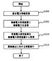
図1は、本発明の一例に係る無線電力送信システムの構成要素を示す。 FIG. 1 shows components of a wireless power transmission system according to an example of the present invention.
図1を参照すると、無線電力送信システム1は、無線電力送信装置10と少なくとも一つの無線電力受信装置30を備える。無線電力送信装置10は、主コイル(primary coil)12、及び主コイル12に連結されて電磁場を発生するために前記主コイルに電気駆動信号を印加するための電気駆動ユニット14を有する。制御ユニット16が電気駆動ユニット14に連結される。この制御ユニット16は、主コイル12が誘導磁場を発生させる時、必要なAC信号を制御する制御信号106を生成する。
Referring to FIG. 1, the wireless
無線電力送信装置10は、任意の適する形態を有することができるが、好ましい形態は、電力送信表面を有する平坦なプラットホームであり、このプラットホーム上に又はその近くに各々の無線電力受信装置30が置かれることができる。
The wireless
無線電力受信装置30は、無線電力送信装置10から分離可能であり、無線電力受信装置30が無線電力送信装置10の近くにある時、無線電力送信装置10により発生される電磁場と結合される補助コイル(secondary coil)32を有する。この方式により、直接的な電気接触なしに無線電力送信装置10から無線電力受信装置30に電力が送信されることができる。この時、主コイル12と補助コイル32は、互いに磁気誘導カップリング又は共振誘導カップリングされたという。
The wireless
主コイル12と補助コイル32は、任意の適する形態を有することができ、例えば、フェライト又は非晶質金属のような高透磁率の形成物の周囲に巻かれた銅線である。補助コイル32は、単一コイル形態であってもよく、デュアル(dual)コイル形態であってもよい。または、補助コイル32は、2個以上のコイルを含むこともできる。
The
無線電力受信装置30は、普通外部負荷(図示せず。ここでは無線電力受信装置の実際負荷とも呼ばれる)に連結され、無線電力送信装置10から受信された無線電力を外部負荷に供給する。無線電力受信装置30は、携帯型電気又は電子デバイス又は再充電可能バッテリ又は電池のような電力を要求する物体で運搬されることができる。
The
図1の無線電力送信システム1の無線電力受信装置30は、補助コイル32に連結された電力測定ユニット31をさらに備える。
The
電力測定ユニット31は、無線電力受信装置30が要求する電力を示す要求電力情報33を生成し、これを制御ユニット16に送信する。要求電力情報33は、無線電力受信装置30が供給を受ける無線電力を制御するための制御情報である。図1の無線電力送信システム1は、無線電力受信装置30から無線電力送信装置10への経路にのみ制御情報が送信される単方向通信方式をサポートする。
The
一例として、要求電力情報33は、無線電力受信装置30が必要な電力の量を数値的に指示することができる。例えば、無線電力受信装置30が10Wの電力を必要とする場合、電力測定ユニット31は、10Wを指示する要求電力情報33を生成することができる。
As an example, the required
制御ユニット16は、要求電力情報33を確認し、要求電力情報33で指示した電力が生成されるように制御信号106を発生させる。例えば、要求電力情報33が10Wを指示する時、制御ユニット16は、10Wが送信されるように制御信号106を発生させる。電気駆動ユニット14は、主コイル12の近くで誘導又は共振磁場を発生するために、制御信号106を受信し、主コイル12でのAC電流信号に変換する。
The
電力測定ユニット31は、AC電流信号によって主コイル12から補助コイル32に伝達される(transferred)無線電力(又は、受信される無線電力)の測定を実行する。電力測定ユニット31により測定された電力は、主コイル12から補助コイル32に伝達される無線電力とシステム1の周辺に存在する寄生負荷など、異物による他の損失の差で算出されることができる。
The
例えば、要求電力情報33によって主コイル12から10Wの無線電力が生成され、補助コイル32に伝達され、異物により2Wの電力が流失されると仮定する。この時、補助コイル32に実際伝達される電力(即ち、補助コイル32が実際受信する電力)は、8Wである。補助コイル32が実際受信する電力を受信電力(received power)といい、受信電力は、無線電力送信装置により生成される磁場(magnetic field)により無線電力受信装置内で消散される(dissipated)総電力の量がである。
For example, it is assumed that 10 W of wireless power is generated from the
電力測定ユニット31は、要求電力と測定された(又は、実際受信される)電力とを比較分析した電力測定実行の結果を報告する受信電力測定結果(measurement result)34を制御ユニット16に送信又は提供する。
The
一実施例として、電力測定ユニット31は、要求電力と測定された電力との間の差分値を受信電力測定結果34で表すことができる。この場合、受信電力測定結果34は、2Wを指示する。
As an example, the
他の実施例として、電力測定ユニット31は、測定された電力値自体を受信電力測定結果34で表すことができる。この場合、受信電力測定結果34は、8Wを指示する。
As another example, the
他の実施例として、電力測定ユニット31は、要求電力と測定された電力との間に差があるかどうかを指示するフラッグ(flag)形態(0又は1)を受信電力測定結果34で表すことができる。例えば、要求電力と測定された電力との間に差がある場合、フラッグ=1に設定され、差がない場合、フラッグ=0に設定される。もちろん、この反対の場合も可能である。前記例の場合、受信電力測定結果34は、1を指示する。
As another example, the
他の実施例として、電力測定ユニット31は、要求電力と測定された電力との間の差が閾値(threshold)より大きいか、又は等しいか、又は小さいかを判断し、この判断の結果を受信電力測定結果34で表すことができる。例えば、要求電力と測定された電力との間の差が閾値より大きい場合、受信電力測定結果=1に設定され、要求電力と測定された電力との間の差が閾値より小さいか、又は等しい場合、受信電力測定結果=0に設定されることができる。前記例において、もし、閾値が1Wとすると、流失される電力2Wは、1Wより大きいため、受信電力測定結果34は、1を指示する。要求電力と測定された電力との間の差が閾値より大きい場合、これは異物が感知されたことを意味するため、受信電力測定結果=1は、FOD(foreign object detection)宣言と同じ意味を有する。例えば、所定時間受信電力測定結果=1が持続的に維持されて変わらない場合には異物が継続存在することを示すため、無線電力送信装置10は、無線電力送信を中断又は遮断することができる。
As another example, the
他の実施例として、電力測定ユニット31は、要求電力と測定された電力との間に差がある場合、これはFODと同じ意味を有し、これを示す受信電力測定結果34を制御ユニット16に提供し、差がない場合、何らの信号を制御ユニット16に提供しない。
As another example, if there is a difference between the required power and the measured power, the
受信電力測定結果34を受けた制御ユニット16は、無線電力送信装置10の近くに相当な寄生負荷が存在すると判断されると、主コイル12の駆動が減少又は中断される遮断モードに入って寄生負荷の発熱を防止することができる。これにより、非効率的な誘導電力の供給が制限又は中断されることができる。これは異物が検出されたことに対して、無線電力送信装置10が措置を行うことである。または、電力測定ユニット31が主コイル12の駆動を減少又は中断させる遮断モードに入って寄生負荷の発熱を防止することができる。これは異物が検出されたことに対して、無線電力受信装置30が措置を行うことである。
When it is determined that there is a considerable parasitic load near the wireless
このように無線電力受信装置30が単に無線電力送信装置10に信号を送信のみすることではなく、電力測定ユニット31を別途に備えて無線電力送信装置10で送出される電力を測定し、その測定値と自分が要求する電力値を比較し、その結果を無線電力送信装置10に送信する単方向電力制御技術が提供されることができる。
In this way, the wireless
図2は、本発明を利用する無線電力受信装置が異物を感知する方法の一例を示す。 FIG. 2 shows an example of a method for detecting a foreign object by a wireless power receiving apparatus using the present invention.
図2を参照すると、無線電力受信装置30は、無線電力受信装置30が要求する電力を示す要求電力情報を生成する(S200)。
Referring to FIG. 2, the wireless
無線電力受信装置30は、要求電力情報を無線電力送信装置10に送信する(S205)。無線電力送信装置10が要求電力情報に合わせて主コイル12で電力を生成すると、無線電力受信装置30は、補助コイル32を利用して磁気誘導(magnetic induction)又は磁気共振(magnetic resonance)に基づいた無線電力を無線電力送信装置10から受信する(S210)。
The
無線電力受信装置30は、要求電力情報に対応して受信される無線電力を測定する(S215)。この時、測定された電力は、無線電力送信装置10から無線電力受信装置30に伝達される初期(initial)無線電力(又は、要求電力)と周辺に存在する寄生負荷など、異物による他の損失の差で算出されることができる。
The
無線電力受信装置30は、要求電力と測定された電力とを比較分析した結果を報告する受信電力測定結果を無線電力送信装置10に提供する(S225)。
The
一実施例として、無線電力受信装置30は、要求電力と測定された電力との間の差分値を受信電力測定結果34で表すことができる。
As an example, the
他の実施例として、無線電力受信装置30は、測定された電力値自体を受信電力測定結果34で表すことができる。
As another example, the
他の実施例として、無線電力受信装置30は、要求電力と測定された電力との間に差があるかどうかを指示するフラッグ(flag)形態(0又は1)を受信電力測定結果で表すことができる。
As another example, the wireless
他の実施例として、無線電力受信装置30は、要求電力と測定された電力との間の差が閾値(threshold)より大きいか、又は等しいか、又は小さいかを判断し、この判断の結果を受信電力測定結果で表すことができる。
As another example, the
他の実施例として、無線電力受信装置30は、要求電力と測定された電力との間に差がある場合、これを示す受信電力測定結果を無線電力送信装置10に提供し、差がない場合、何らの信号を無線電力送信装置10に提供しない。この場合、ステップS225は省略されることができる。
As another example, when there is a difference between the required power and the measured power, the wireless
他の実施例として、無線電力受信装置30は、測定された電力が要求電力より大きいか、又は小さいかを判断し、これを受信電力測定結果で表すことができる。例えば、受信電力測定結果は‘high’又は‘low’のように表示される。‘high’は、測定された電力が要求電力より大きいことを意味し、‘low’は、測定された電力が要求電力より小さいことを意味する。または、受信電力測定結果は、‘high’又は‘low’又は‘equal’のように三つの状態で表示されることもできる。
As another example, the wireless
図3は、本発明を利用する無線電力送信装置が異物を感知する方法の一例を示す。 FIG. 3 illustrates an example of a method for detecting a foreign object by a wireless power transmission apparatus using the present invention.
図3を参照すると、無線電力送信装置10は、要求電力情報を無線電力受信装置30から受信する(S300)。要求電力情報により表示された要求電力に合わせ、無線電力送信装置10は、磁気誘導又は磁気共振方式に基づいて無線電力を無線電力受信装置30に送信する(S305)。
Referring to FIG. 3, the wireless
無線電力送信装置10は、要求電力によって送信した無線電力が無線電力受信装置30により実際測定された結果を報告する受信電力測定結果を無線電力受信装置30から受信する(S310)。
The wireless
受信電力測定結果を分析した結果、異物が検出されたと判断されると、無線電力送信装置10は、主コイル12の駆動が減少又は中断される遮断モードに進入する。これにより、寄生負荷の発熱が防止され、非効率的な誘導電力の供給が制限又は中断されることができる。
As a result of analyzing the reception power measurement result, when it is determined that a foreign object has been detected, the wireless
図4は、本発明を利用する無線電力送信装置が異物を感知する方法の他の例を示す。 FIG. 4 illustrates another example of a method for detecting a foreign object by a wireless power transmission apparatus using the present invention.
図4を参照すると、ステップS400乃至ステップS410は、各々、ステップS300乃至ステップS310の手順と同様に実行される。一方、ステップS410は、下記の多様な実施例により限定されることができる。 Referring to FIG. 4, steps S400 to S410 are executed in the same manner as the procedures of steps S300 to S310, respectively. Meanwhile, step S410 may be limited by the following various embodiments.
一例として、受信電力測定結果が、測定された電力が要求電力より大きいか(high)、又は小さいか(low)を指示する実施例において、無線電力送信装置10は、‘low’又は‘high’を指示する受信電力測定結果を同一に連続的にN回受信したかを判断する(S415)。ここで、Nは、無線電力送信装置10が無線電力の送信を中断するときに要求される連続的な‘low’又は‘high’の受信回数を示し、N=2である。例えば、‘low’を指示する受信電力測定結果を同一に引き続き2回受信する場合、無線電力送信装置10は、異物検出に対する措置として電力送信を中断することができる(S420)。反対に、‘high’を指示する受信電力測定結果を同一に引き続き2回受信する場合にも、無線電力送信装置10は、異物検出に対する措置として電力送信を中断することができる(S420)。
As an example, in the embodiment in which the received power measurement result indicates whether the measured power is higher (high) or lower (low) than the required power, the wireless
反面、‘low’又は‘high’を指示する受信電力測定結果が連続的に2回未満に受信される場合、無線電力送信装置10は、再び無線電力受信装置30に無線電力を送信する(S405)。例えば、以前に‘low’を指示する受信電力測定結果を受信し、現在‘high’を指示する受信電力測定結果を受信する場合、同一の受信電力測定結果が2回連続して受信されるものではないため、この場合、無線電力送信装置10は、無線電力の送信を中断しない。
On the other hand, when the reception power measurement result indicating “low” or “high” is continuously received less than twice, the wireless
他の例として、受信電力測定結果が要求電力と測定された電力との間に差があることを指示する実施例において、無線電力送信装置10が‘差がある’を指示する受信電力測定結果を同一に連続的にN回受信する場合、無線電力送信装置10は、異物検出に対する措置として電力送信を中断することができる(S420)。
As another example, in the embodiment in which the received power measurement result indicates that there is a difference between the required power and the measured power, the received power measurement result in which the wireless
他の例として、受信電力測定結果が要求電力と測定された電力との間の差が閾値(threshold)より大きいか、又は等しいか、又は小さいかを判断した結果である実施例において、無線電力送信装置10が‘大きい’又は‘小さい’を指示する受信電力測定結果を同一に連続的にN回受信する場合、無線電力送信装置10は、異物検出に対する措置として無線電力の送信を中断することができる(S420)。
As another example, in an embodiment where the received power measurement result is a result of determining whether the difference between the required power and the measured power is greater than, equal to, or less than a threshold, wireless power When the
図5は、本発明の他の例に係る無線電力送信システムの構成要素を示す。 FIG. 5 shows components of a wireless power transmission system according to another example of the present invention.
図5を参照すると、無線電力送信システム4は、無線電力送信装置40と少なくとも一つの無線電力受信装置50を備える。無線電力送信装置40は、主コイル44、及び主コイル44に連結されて電磁場を発生するために主コイル44に電気駆動信号を印加するための電気駆動ユニット43を有する。制御ユニット42が電気駆動ユニット43に連結される。この制御ユニット42は、制御信号45を発生する。電気駆動ユニット43は、主コイル44の近くで誘導又は共振磁場を発生するために、制御信号45を受信し、主コイル44でのAC電流信号に変換する。
Referring to FIG. 5, the wireless power transmission system 4 includes a wireless
無線電力送信装置40は、任意の適する形態を有することができるが、好ましい形態は、電力送信表面を有する平坦なプラットホームであり、このプラットホーム上に又はその近くに各々の無線電力受信装置50が置かれることができる。
The
無線電力受信装置50は、無線電力送信装置40から分離可能であり、無線電力受信装置50が無線電力送信装置40の近くにある時、無線電力送信装置40により発生される電磁場と結合される補助コイル52を有する。この方式により、直接的な電気接触なしに無線電力送信装置40から無線電力受信装置50に電力が伝達されることができる。
The wireless
主コイル44と補助コイル52は、任意の適する形態を有することができ、例えば、フェライト又は非晶質金属のような高透磁率の形成物の周囲に巻かれた銅線である。補助コイル52は、単一コイル形態であってもよく、デュアル(dual)コイル形態であってもよい。または、補助コイル52は、2個以上のコイルを含むこともできる。
The
図5の無線電力送信システム4の無線電力受信装置50は、補助コイル52に連結された補助電力測定ユニット(secondary power measuring unit)51をさらに備える。
The
電力測定ユニット51は、無線電力受信装置50が要求する電力を示す要求電力情報53を生成し、これを制御ユニット42に送信する。要求電力情報53は、無線電力受信装置50が供給を受ける電力を制御するための制御情報である。
The
一例として、要求電力情報53は、無線電力受信装置50が必要な電力の量を数値的に指示することができる。例えば、無線電力受信装置50が10Wの電力を必要とする場合、電力測定ユニット51は、10Wを指示する要求電力情報53を生成することができる。
As an example, the required
制御ユニット42は、要求電力情報53を確認し、要求電力情報53で指示した電力が生成されるように制御信号45を発生させる。例えば、要求電力情報53が10Wを指示する時、制御ユニット42は、10Wが送信されるように制御信号45を発生させる。電気駆動ユニット43は、主コイル44の近くで誘導又は共振磁場を発生するために、制御信号45を受信し、主コイル44でのAC電流信号に変換する。
The
無線電力送信装置40は、主電力測定ユニット(primary power measuring unit)41をさらに含む。主電力測定ユニット41は、AC電流信号によって主コイル44で生成される電力を測定する。例えば、要求電力情報53が10Wを指示するが、実際生成される電力は12Wで測定されることができる。即ち、要求電力情報53の指示(indication)のように無線電力受信装置50が実際受信する電力が10Wになるために、主コイル44ではその以上である12Wを生成することである。これは主コイル44から補助コイル52に無線電力が送信される過程でシステム4の周辺に存在する寄生負荷など、異物によって2Wの損失が発生したためであると判断することができる。
The wireless
制御ユニット42は、主電力測定ユニット41により測定された生成電力を指示する生成電力測定報告(measurement report of the generated power)54を構成(又は、生成)し、電力測定ユニット51に送信する。このように無線電力送信システム4は、無線電力受信装置50から無線電力送信装置40への経路に制御情報53が送信されることもでき、無線電力送信装置40から無線電力受信装置50への経路に制御情報54、55が送信されることもできる双方向通信方式をサポートする。
The
電力測定ユニット51は、生成電力測定報告54により指示される(indicated)電力と要求電力との間の差を比較分析し、異物感知宣言(FOD宣言)をするかどうかを判断する。
The
一実施例として、電力測定ユニット51は、生成電力測定報告54により指示される電力と要求電力との間の差が閾値より大きいか、又は等しいか、又は小さいかを判断し、この判断の結果を受信電力測定結果(measurement result)55で表すことができる。例えば、生成電力測定報告54により指示される電力と要求電力との間の差が閾値より大きい場合、電力測定ユニット51は、受信電力測定結果=1に設定し、生成電力測定報告54により指示される電力と要求電力との間の差が閾値より小さいか、又は等しい場合、電力測定ユニット51は、受信電力測定結果=0に設定することができる。または、生成電力測定報告54により指示される電力と要求電力との間の差が閾値より大きいか、又は等しい場合、電力測定ユニット51は、受信電力測定結果=1に設定し、生成電力測定報告54により指示される電力と要求電力との間の差が閾値より小さい場合、電力測定ユニット51は、受信電力測定結果=0に設定することもできる。もちろん、受信電力測定結果55の値0と1が各々指示することは互いに変わることもできる。
As an example, the
例えば、閾値が1Wと仮定する。前記の例のように、生成電力測定報告54により指示される電力が12Wであり、要求電力は10Wである場合、その差は2Wであり、これは閾値である1Wより大きい。この場合、受信電力測定結果34は、1を指示する。生成電力測定報告54により指示される電力と要求電力との間の差が閾値より大きい場合、これは異物が感知されたことを意味する。
For example, assume that the threshold is 1 W. As in the above example, when the power indicated by the generated
前記では電力測定ユニット51が異物感知宣言をするにあたって、生成電力測定報告54により指示される電力と要求電力との間の差を比較分析すると説明した。しかし、電力測定ユニット51は、生成電力測定報告54により指示される電力と無線電力受信装置50が実際受信する電力との間の差を比較分析して異物感知宣言をすることもできる。この時、比較分析の方式は、生成電力測定報告54により指示される電力と要求電力との間の差を比較分析する方式と同様に実行されることができる。
In the above description, when the
無線電力送信装置40が異物による損失のため要求電力(又は、無線電力受信装置50が実際受信する電力)に比べて一定量以上大きい無線電力又は過度な無線電力を送信して要求電力を満たす場合、これは無線電力効率を減少させるため、FOD宣言をして電力送信を中断又は遮断することが好ましい。これにより、受信電力測定結果=1は、FOD宣言と同じ意味を有することもできる。例えば、所定時間受信電力測定結果=1が持続的に維持されて変わらない場合には異物が引き続き存在することを意味し、無線電力送信装置40は、無線電力送信を中断又は遮断することができる。
When the wireless
受信電力測定結果55を受けた制御ユニット42は、無線電力送信装置40の近くに相当な寄生負荷が存在すると判断されると、主コイル44の駆動が減少又は中断される遮断モードに入って寄生負荷の発熱を防止することができる。これにより、非効率的な誘導電力の供給が制限又は中断されることができる。これは異物が検出されたことに対して、無線電力送信装置40が措置を行うことである。または、電力測定ユニット51が主コイル44の駆動を減少又は中断させる遮断モードに入って寄生負荷の発熱を防止することができる。これは異物が検出されたことに対して、無線電力受信装置50が措置を行うことである。
The
このように、本発明は、無線電力送信装置40が無線電力受信装置50に無線電力を送信のみすることではなく、制御ユニット42が無線電力送信装置40で生成又は送信される電力を指示する生成電力測定報告を無線電力受信装置50に送信する双方向電力制御技術を提供する。
Thus, in the present invention, the wireless
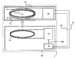
図6は、本発明の他の例に係る無線電力送信システムの構成要素を示す。 FIG. 6 shows components of a wireless power transmission system according to another example of the present invention.
図6を参照すると、無線電力送信装置60は、図1の無線電力送信装置10と同一の構成要素を有する。一方、無線電力受信装置70は、図1の無線電力受信装置30と比較して測定用コイル71をさらに備え、残りの構成要素は同じである。電力測定ユニット31は、測定用コイル71に連結される。測定用コイル71は、補助コイル52の外側を囲む形態で備えられることもでき、補助コイル52の内側を囲む形態で補助コイル52の内側に備えられることもできる。
Referring to FIG. 6, the wireless
主コイル12と補助コイル52との間の磁気誘導又は磁気共振により補助コイル52に一時的に磁場又は電流又は電圧が誘導されると、測定用コイル71に2次的に磁場又は電流又は電圧が誘導される。電力測定ユニット31は、測定用コイル71に2次的に誘導される磁場又は電流又は電圧を利用して受信される無線電力を測定することができる。
When a magnetic field, current, or voltage is temporarily induced in the
図6では、測定用コイル71が図1の無線電力受信装置30に追加的に構成される例示を説明したが、測定用コイル71は、図5での無線電力受信装置50にも同様に含まれることができることはもちろんである。
6 illustrates an example in which the
図7は、本発明を利用する無線電力受信装置が異物を感知する方法の他の例を示す。 FIG. 7 illustrates another example of a method for detecting a foreign object by a wireless power receiving apparatus using the present invention.
図7を参照すると、無線電力受信装置50は、無線電力受信装置50が要求する電力を示す要求電力情報を生成する(S700)。
Referring to FIG. 7, the wireless
無線電力受信装置50は、要求電力情報を無線電力送信装置40に送信する(S705)。無線電力送信装置40が要求電力情報に合わせて電力を生成すると、無線電力受信装置50は、磁気誘導又は共振誘導方式に基づいた無線電力を無線電力送信装置40から受信する(S710)。
The wireless
無線電力受信装置50は、無線電力送信装置40が生成する電力を測定した生成電力測定報告を無線電力送信装置40から受信する(S715)。ここで、無線電力送信装置40が生成する電力は、異物による他の損失が介入されないものであり、無線電力受信装置50が実際受信する無線電力と異なる。例えば、異物による他の損失が介入される場合、無線電力受信装置50が実際受信する無線電力は、生成電力より低く測定されることができる。
The
無線電力受信装置50は、要求電力(又は、実際受信された電力)と生成電力測定報告により指示される電力とを比較分析して異物感知宣言(FOD宣言)をするかどうかを判断する(S720)。
The wireless
一実施例として、無線電力受信装置50は、生成電力測定報告により指示される電力と要求電力との間の差が閾値より大きいか、又は等しいか、又は小さいかを判断し、この判断の結果を受信電力測定結果で表すことができる。例えば、生成電力測定報告により指示される電力と要求電力との間の差が閾値より大きい場合、無線電力受信装置50は、受信電力測定結果=1に設定し、生成電力測定報告により指示される電力と要求電力との間の差が閾値より小さいか、又は等しい場合、無線電力受信装置50は、受信電力測定結果=0に設定することができる。または、生成電力測定報告により指示される電力と要求電力との間の差が閾値より大きいか、又は等しい場合、無線電力受信装置50は、受信電力測定結果=1に設定し、生成電力測定報告により指示される電力と要求電力との間の差が閾値より小さい場合、無線電力受信装置50は、受信電力測定結果=0に設定することもできる。もちろん、受信電力測定結果の値0と1が各々指示するものは互いに変わることもできる。
As an example, the
例えば、閾値が1Wと仮定する。前記の例のように、生成電力測定報告により指示される電力が12Wであり、要求電力は10Wである場合、その差は2Wであり、これは閾値である1Wより大きい。この場合、受信電力測定結果は、1を指示する。生成電力測定報告により指示される電力と要求電力との間の差が閾値より大きい場合、これは異物が感知されたことを意味する。 For example, assume that the threshold is 1 W. As in the above example, when the power indicated by the generated power measurement report is 12 W and the required power is 10 W, the difference is 2 W, which is larger than the threshold value of 1 W. In this case, the received power measurement result indicates 1. If the difference between the power indicated by the generated power measurement report and the required power is greater than the threshold, this means that a foreign object has been detected.
無線電力受信装置50は、比較分析の結果を報告する受信電力測定結果を無線電力送信装置40に送信する(S725)。
The
図8は、本発明を利用する無線電力送信装置が異物を感知する方法の他の例を示す。 FIG. 8 illustrates another example of a method for detecting a foreign object by a wireless power transmission apparatus using the present invention.
図8を参照すると、無線電力送信装置40は、要求電力情報を無線電力受信装置50から受信する(S800)。要求電力情報により表示された要求電力に合わせ、無線電力送信装置40は、磁気誘導方式に基づいて無線電力を生成する。即ち、無線電力送信装置40は、要求電力情報を確認し、要求電力情報で指示した電力が誘導されるように制御信号を発生させる。例えば、要求電力情報が10Wを指示する時、無線電力送信装置40は、10Wが送信されるように制御信号を発生させる。無線電力送信装置40は、主コイル44の近くで誘導電磁場を発生するために、制御信号を受信し、主コイル44でのAC電流信号に変換する。
Referring to FIG. 8, the wireless
無線電力送信装置40は、生成される無線電力を無線電力受信装置50に送信する(S805)。
The wireless
この時、無線電力送信装置40は、AC電流信号によって主コイル44で生成される電力を測定する(S810)。例えば、要求電力情報が10Wを指示するが、実際生成される電力は12Wで測定されることができる。即ち、要求電力情報の指示(indication)のように10Wを無線電力受信装置に伝達するために、主コイル44ではその以上である12Wを生成することである。これは主コイル44から補助コイル52に無線電力が送信される過程で寄生負荷など、異物によって2Wの損失が発生したためであると判断することができる。
At this time, the wireless
無線電力送信装置40は、測定された生成電力を指示する生成電力測定報告を構成し、無線電力受信装置50に送信する(S815)。このように無線電力送信装置40から無線電力受信装置50への経路に制御情報が送信されることもでき、無線電力受信装置50から無線電力送信装置40への経路に制御情報が送信されることもできる双方向通信方式が可能となる。
The
無線電力送信装置40は、要求電力(又は、実際受信された電力)と生成電力測定報告により指示される電力とを比較分析した結果である受信電力測定結果を無線電力受信装置50から受信する(S820)。
The wireless
受信電力測定結果は、生成電力測定報告により指示される電力と要求電力との間の差が閾値より大きいか、又は等しいか、又は小さいかを指示する情報である。例えば、生成電力測定報告により指示される電力と要求電力との間の差が閾値より大きい場合、補助受信電力測定結果=1に設定され、生成電力測定報告により指示される電力と要求電力との間の差が閾値より小さいか、又は等しい場合、受信電力測定結果=0に設定されることができる。または、反対に、生成電力測定報告により指示される電力と要求電力との間の差が閾値より大きいか、又は等しい場合、受信電力測定結果=1に設定され、生成電力測定報告により指示される電力と要求電力との間の差が閾値より小さい場合、受信電力測定結果=0に設定されることもできる。もちろん、受信電力測定結果の値0と1が各々指示するものは互いに変わることもできる。 The received power measurement result is information indicating whether the difference between the power indicated by the generated power measurement report and the required power is larger than, equal to, or smaller than the threshold value. For example, when the difference between the power indicated by the generated power measurement report and the required power is larger than the threshold value, the auxiliary reception power measurement result is set to 1, and the power indicated by the generated power measurement report and the required power If the difference between them is less than or equal to the threshold, the received power measurement result = 0 can be set. Or, conversely, if the difference between the power indicated by the generated power measurement report and the required power is greater than or equal to the threshold, the received power measurement result = 1 is set and indicated by the generated power measurement report. If the difference between the power and the required power is smaller than the threshold value, the received power measurement result = 0 can also be set. Of course, the received power measurement result values 0 and 1 can be changed from each other.
例えば、閾値が1Wと仮定する。前記の例のように、生成電力測定報告により指示される電力が12Wであり、要求電力は10Wである場合、その差は2Wであり、これは閾値である1Wより大きい。この場合、受信電力測定結果は、1を指示する。生成電力測定報告により指示される電力と要求電力との間の差が閾値より大きい場合、これは異物が感知されたことを意味する。したがって、無線電力送信装置40は、これを異物感知宣言であると認識することができる。
For example, assume that the threshold is 1 W. As in the above example, when the power indicated by the generated power measurement report is 12 W and the required power is 10 W, the difference is 2 W, which is larger than the threshold value of 1 W. In this case, the received power measurement result indicates 1. If the difference between the power indicated by the generated power measurement report and the required power is greater than the threshold, this means that a foreign object has been detected. Therefore, the wireless
受信電力測定結果を分析した結果、異物が検出されたと判断されると、無線電力送信装置40は、異物検出に対する措置を実行する(S825)。例えば、無線電力送信装置40は、主コイル12の駆動が減少又は中断される遮断モードに進入することができる。これにより、寄生負荷の発熱が防止され、非効率的な誘導電力の供給が制限又は中断されることができる。
As a result of analyzing the reception power measurement result, if it is determined that a foreign object is detected, the wireless
図9は、本発明を利用する無線電力送信装置と無線電力受信装置との間の動作フローチャートである。 FIG. 9 is an operation flowchart between the wireless power transmitting apparatus and the wireless power receiving apparatus using the present invention.
図9を参照すると、無線電力受信装置は、無線電力受信装置が要求する電力を示す要求電力情報を生成する(S900)。 Referring to FIG. 9, the wireless power receiving apparatus generates requested power information indicating the power required by the wireless power receiving apparatus (S900).
無線電力受信装置は、要求電力情報を無線電力送信装置に送信する(S905)。無線電力送信装置が要求電力情報に合わせて主コイルで電力を生成すると、無線電力受信装置は、補助コイルを利用して磁気誘導(magnetic induction)又は磁気共振(magnetic resonance)に基づいた無線電力を無線電力送信装置から受信する(S910)。 The wireless power receiver transmits the requested power information to the wireless power transmitter (S905). When the wireless power transmitter generates power in the main coil according to the required power information, the wireless power receiver uses the auxiliary coil to generate wireless power based on magnetic induction or magnetic resonance. Received from the wireless power transmission apparatus (S910).
無線電力受信装置は、 前記無線電力を測定することもできる。この時、測定された電力は、無線電力送信装置から無線電力受信装置に伝達される最初/初期(initial)無線電力(又は、要求電力)と周辺に存在する寄生負荷など、異物による他の損失の差で算出されることができる。 The wireless power receiving apparatus can also measure the wireless power. At this time, the measured power is the other loss due to foreign objects such as initial / initial wireless power (or required power) transmitted from the wireless power transmitting device to the wireless power receiving device and the parasitic load existing in the vicinity. It can be calculated by the difference between
無線電力受信装置は、要求電力と測定された電力とを比較分析した結果を報告する受信電力測定結果を無線電力送信装置に提供する(S920)。 The wireless power receiving device provides the wireless power transmitting device with a received power measurement result that reports a result of comparing and analyzing the required power and the measured power (S920).
一実施例として、受信電力測定結果は、要求電力と測定された電力との間の差分値で定義されることができる。 As an example, the received power measurement result may be defined as a difference value between the required power and the measured power.
他の実施例として、受信電力測定結果は、測定された電力値自体で定義されることができる。 As another example, the received power measurement result may be defined by the measured power value itself.
他の実施例として、受信電力測定結果は、要求電力と測定された電力との間に差があるかどうかを指示するフラッグ(flag)形態(0又は1)で定義されることもできる。 As another example, the received power measurement result may be defined in a flag form (0 or 1) indicating whether there is a difference between the required power and the measured power.
他の実施例として、受信電力測定結果は、要求電力と測定された電力との間の差が閾値(threshold)より大きいか、又は等しいか、又は小さいかに対する判断の結果で定義されることができる。 As another example, the received power measurement result may be defined as a result of a determination as to whether the difference between the required power and the measured power is greater than, equal to, or less than a threshold. it can.
他の実施例として、受信電力測定結果は、要求電力と測定された電力との間に差がある場合にのみ、無線電力送信装置に送信される情報で定義されることができる。即ち、要求電力と測定された電力との間に差がない場合、受信電力測定結果は、無線電力送信装置に送信されない。この場合、ステップS920は省略されることができる。 As another example, the reception power measurement result may be defined by information transmitted to the wireless power transmission apparatus only when there is a difference between the required power and the measured power. That is, when there is no difference between the required power and the measured power, the reception power measurement result is not transmitted to the wireless power transmission apparatus. In this case, step S920 can be omitted.
他の実施例として、受信電力測定結果は、測定された電力が要求電力より大きいか、又は小さいかに対する判断の結果で定義されることができる。例えば、受信電力測定結果は、‘high’又は‘low’のように表示される。‘high’は、測定された電力が要求電力より大きいことを意味し、‘low’は、測定された電力が要求電力より小さいことを意味する。または、受信電力測定結果は、‘high’又は‘low’又は‘equal’のように三つの状態で表示されることもできる。 As another example, the received power measurement result may be defined as a result of a determination as to whether the measured power is greater than or less than the required power. For example, the received power measurement result is displayed as 'high' or 'low'. 'High' means that the measured power is larger than the required power, and 'low' means that the measured power is smaller than the required power. Alternatively, the reception power measurement result may be displayed in three states such as 'high', 'low', or 'equal'.
受信電力測定結果を分析した結果、異物が検出されたと判断されると、異物検出に対する措置を実行する(S925)。例えば、無線電力送信装置は、主コイルの駆動が減少又は中断される遮断モードに進入する。これにより、寄生負荷の発熱が防止され、非効率的な誘導電力の供給が制限又は中断されることができる。 As a result of analyzing the received power measurement result, if it is determined that a foreign object has been detected, a measure for foreign object detection is executed (S925). For example, the wireless power transmission device enters a cut-off mode in which the driving of the main coil is reduced or interrupted. Thereby, heat generation of the parasitic load is prevented, and the supply of inefficient inductive power can be limited or interrupted.
無線電力送信装置の異物検出に対する措置は、下記の実施例を含むことができる。一例として、受信電力測定結果が、測定された電力が要求電力より大きいか(high)、又は小さいか(low)を指示する実施例において、無線電力送信装置は、‘low’又は‘high’を指示する受信電力測定結果を同一に連続的にN回受信したかを判断する。ここで、Nは、無線電力送信装置が無線電力の送信を中断するときに要求される連続的な‘low’又は‘high’の受信回数を示し、N=2である。例えば、‘low’を指示する受信電力測定結果を同一に引き続き2回受信する場合、無線電力送信装置は、異物検出に対する措置として電力送信を中断することができる。反対に、‘high’を指示する受信電力測定結果を同一に引き続き2回受信する場合にも、無線電力送信装置は、異物検出に対する措置として電力送信を中断することができる。 Measures against foreign object detection of the wireless power transmission device can include the following embodiments. As an example, in an embodiment in which the received power measurement result indicates whether the measured power is higher than the required power (high) or lower (low), the wireless power transmission apparatus may set 'low' or 'high'. It is determined whether the instructed received power measurement result is received N times continuously in the same manner. Here, N indicates the number of continuous reception of 'low' or 'high' required when the wireless power transmission apparatus interrupts transmission of wireless power, and N = 2. For example, when the reception power measurement result indicating “low” is received twice in succession, the wireless power transmission apparatus can interrupt power transmission as a measure against foreign object detection. On the other hand, even when the reception power measurement result indicating “high” is received twice in succession, the wireless power transmission device can interrupt power transmission as a measure against foreign object detection.
反面、‘low’又は‘high’を指示する受信電力測定結果が連続的に2回未満に受信される場合、無線電力送信装置は、異物が検出されなかったと判断し、再び無線電力受信装置に無線電力を送信することができる。例えば、以前に‘low’を指示する受信電力測定結果を受信し、現在‘high’を指示する受信電力測定結果を受信する場合、同一の受信電力測定結果が2回連続に受信されるものではないため、この場合、無線電力送信装置は、無線電力の送信を中断しない。 On the other hand, if the reception power measurement result indicating “low” or “high” is continuously received less than twice, the wireless power transmission device determines that no foreign object has been detected, and again returns to the wireless power reception device. Wireless power can be transmitted. For example, when a reception power measurement result indicating “low” has been received before and a reception power measurement result indicating “high” is received, the same reception power measurement result is received twice consecutively. Therefore, in this case, the wireless power transmission device does not interrupt transmission of wireless power.
他の例として、受信電力測定結果が要求電力と測定された電力との間に差があることを指示する実施例において、‘差がある’を指示する受信電力測定結果を同一に連続的にN回受信する場合、無線電力送信装置は、異物検出に対する措置として電力送信を中断することができる。 As another example, in the embodiment in which the received power measurement result indicates that there is a difference between the required power and the measured power, the received power measurement result indicating “there is a difference” is continuously changed. When receiving N times, the wireless power transmission device can interrupt power transmission as a measure against foreign object detection.
他の例として、受信電力測定結果が要求電力と測定された電力との間の差が閾値(threshold)より大きいか、又は等しいか、又は小さいかを判断した結果である実施例において、無線電力送信装置が‘大きさ’又は‘小ささ’を指示する受信電力測定結果を同一に連続的にN回受信する場合、無線電力送信装置は、異物検出に対する措置として無線電力の送信を中断することができる。 As another example, in an embodiment where the received power measurement result is a result of determining whether the difference between the required power and the measured power is greater than, equal to, or less than a threshold, wireless power When the transmission device receives the received power measurement result indicating “size” or “smallness” N times continuously in succession, the wireless power transmission device interrupts transmission of wireless power as a measure against foreign object detection. Can do.
前述した全ての機能は、前記機能を遂行するようにコーディングされたソフトウェアやプログラムコードなどによるマイクロプロセッサ、制御器、マイクロ制御器、ASIC(Application Specific Integrated Circuit)などのようなプロセッサにより実行されることができる。前記コードの設計、開発及び具現は、本発明の説明に基づいて当業者に自明であるということができる。 All the functions described above are executed by a processor such as a microprocessor, a controller, a microcontroller, an ASIC (Application Specific Integrated Circuit), or the like, which is coded to perform the function. Can do. It can be said that the design, development and implementation of the code are obvious to those skilled in the art based on the description of the present invention.
以上、本発明に対して実施例を参照して説明したが、該当技術分野の通常の知識を有する者は、本発明の技術的思想及び領域から外れない範囲内で本発明を多様に修正及び変更させて実施可能であることを理解することができる。したがって、本発明は、前述した実施例に限定されるものではなく、特許請求の範囲の範囲内の全ての実施例を含む。 Although the present invention has been described with reference to the embodiments, those skilled in the art can make various modifications and modifications to the present invention without departing from the technical idea and scope of the present invention. It can be understood that it can be implemented with changes. Accordingly, the present invention is not limited to the embodiments described above, but includes all embodiments within the scope of the claims.
Claims (15)
無線電力送信装置に備えられた主コイルとカップリングされて無線電力を受信する補助コイル、及び、
無線充電に必要な要求電力を示す要求電力情報を生成し、前記要求電力情報を前記無線電力送信装置に送信し、前記受信される無線電力を測定する電力測定ユニット、を含み、
前記電力測定ユニットは、前記要求電力と前記測定された無線電力とを比較分析した受信電力測定結果を構成して前記無線電力送信装置に送信することを特徴とする無線電力受信装置。 In the wireless power receiver that detects foreign matter,
An auxiliary coil coupled to a main coil provided in the wireless power transmission device to receive wireless power; and
A power measuring unit that generates required power information indicating required power required for wireless charging, transmits the required power information to the wireless power transmission device, and measures the received wireless power;
The wireless power receiving apparatus, wherein the power measurement unit forms a reception power measurement result obtained by comparing and analyzing the required power and the measured wireless power, and transmits the result to the wireless power transmission apparatus.
無線電力送信装置に備えられた主コイルとカップリングされて無線電力を受信する補助コイル、及び、
無線充電に必要な要求電力を示す要求電力情報を生成し、前記無線電力送信装置により生成された無線電力を指示する生成電力測定報告を前記無線電力送信装置から受信し、前記要求電力と前記生成された無線電力とを比較分析した受信電力測定結果を構成し、前記要求電力情報と前記受信電力測定結果を前記無線電力送信装置に送信する電力測定ユニット、を含むことを特徴とする無線電力受信装置。 In the wireless power receiver that detects foreign matter,
An auxiliary coil coupled to a main coil provided in the wireless power transmission device to receive wireless power; and
Generates required power information indicating required power required for wireless charging, receives a generated power measurement report indicating the wireless power generated by the wireless power transmitting device from the wireless power transmitting device, and generates the required power and the generated A wireless power reception unit comprising: a power measurement unit that configures a reception power measurement result obtained by comparing and analyzing the received wireless power, and transmits the required power information and the reception power measurement result to the wireless power transmission device apparatus.
無線充電に必要な要求電力を示す要求電力情報を生成するステップ、
前記要求電力情報を無線電力送信装置に送信するステップ、
前記無線電力送信装置に備えられた主コイルとカップリングされた補助コイルを利用して無線電力を受信するステップ、
前記受信される無線電力を測定するステップ、
前記要求電力と前記測定された無線電力とを比較分析した受信電力測定結果を構成するステップ、及び、
前記受信電力測定結果を前記無線電力送信装置に送信するステップ、を含むことを特徴とする無線電力受信方法。 In the wireless power receiving method by the wireless power receiving device for detecting a foreign object,
Generating required power information indicating required power required for wireless charging;
Transmitting the required power information to a wireless power transmission device;
Receiving wireless power using an auxiliary coil coupled to a main coil provided in the wireless power transmitter;
Measuring the received wireless power;
Configuring a received power measurement result obtained by comparing and analyzing the required power and the measured wireless power; and
Transmitting the received power measurement result to the wireless power transmitting apparatus.
無線電力受信装置の充電に必要な要求電力を示す要求電力情報を前記無線電力受信装置から受信し、前記要求電力を提供するための制御信号を発生させて電気駆動ユニットに送信する制御ユニット、
前記制御信号に基づいて主コイルに電気駆動信号を印加する前記電気駆動ユニット、及び、
前記電気駆動ユニットに連結され、前記無線電力受信装置に備えられた補助コイルとカップリングされて無線電力を送信する前記主コイル、を含み、
前記制御ユニットは、前記無線電力受信装置で測定された無線電力と前記要求電力とを比較分析した受信電力測定結果を前記無線電力受信装置から受信することを特徴とする無線電力送信装置。 In the wireless power transmission device for detecting foreign matter,
A control unit that receives required power information indicating required power required for charging the wireless power receiving device from the wireless power receiving device, generates a control signal for providing the required power, and transmits the control signal to the electric drive unit;
The electric drive unit for applying an electric drive signal to the main coil based on the control signal; and
The main coil coupled to the electric drive unit and coupled with an auxiliary coil provided in the wireless power receiving device to transmit wireless power;
The wireless power transmission device, wherein the control unit receives a reception power measurement result obtained by comparing and analyzing the wireless power measured by the wireless power reception device and the required power from the wireless power reception device.
無線電力受信装置の充電に必要な要求電力を示す要求電力情報を前記無線電力受信装置から受信するステップ、
前記要求電力を提供するための制御信号を発生させて前記無線電力送信装置に備えられた主コイルに電気駆動信号を印加するステップ、
前記電気駆動信号の印加によって前記主コイルで生成される無線電力を前記主コイルにカップリングされる補助コイルを備えた前記無線電力受信装置に送信するステップ、及び、
前記無線電力受信装置で測定された無線電力と前記要求電力とを比較分析した受信電力測定結果を前記無線電力受信装置から受信するステップ、を含むことを特徴とする無線電力送信方法。 In a wireless power transmission method by a wireless power transmission device that detects a foreign object,
Receiving required power information indicating required power required for charging the wireless power receiving device from the wireless power receiving device;
Generating a control signal for providing the required power and applying an electric drive signal to a main coil provided in the wireless power transmission device;
Transmitting wireless power generated by the main coil by application of the electric drive signal to the wireless power receiving device including an auxiliary coil coupled to the main coil; and
Receiving a reception power measurement result obtained by comparing and analyzing the wireless power measured by the wireless power reception device and the required power from the wireless power reception device.
Applications Claiming Priority (2)
| Application Number | Priority Date | Filing Date | Title |
|---|---|---|---|
| KR10-2012-0075276 | 2012-07-10 | ||
| KR1020120075276A KR102074475B1 (en) | 2012-07-10 | 2012-07-10 | Apparatus and method for detecting foreign object in wireless power transmitting system |
Publications (2)
| Publication Number | Publication Date |
|---|---|
| JP2014018061A true JP2014018061A (en) | 2014-01-30 |
| JP6261212B2 JP6261212B2 (en) | 2018-01-17 |
Family
ID=48782221
Family Applications (1)
| Application Number | Title | Priority Date | Filing Date |
|---|---|---|---|
| JP2013142642A Active JP6261212B2 (en) | 2012-07-10 | 2013-07-08 | Foreign object detection device and method in wireless power transmission system |
Country Status (5)
| Country | Link |
|---|---|
| US (6) | US9762092B2 (en) |
| EP (2) | EP2685583B1 (en) |
| JP (1) | JP6261212B2 (en) |
| KR (1) | KR102074475B1 (en) |
| CN (6) | CN103545937B (en) |
Cited By (2)
| Publication number | Priority date | Publication date | Assignee | Title |
|---|---|---|---|---|
| KR20150057944A (en) * | 2013-11-18 | 2015-05-28 | 리치테크 테크놀로지 코포레이션 | Power calculating method adopted in wireless power system |
| WO2015118967A1 (en) * | 2014-02-10 | 2015-08-13 | ローム株式会社 | Wireless power receiver and control circuit therefor, electronic device using same, and error detection method |
Families Citing this family (36)
| Publication number | Priority date | Publication date | Assignee | Title |
|---|---|---|---|---|
| KR102074475B1 (en) | 2012-07-10 | 2020-02-06 | 지이 하이브리드 테크놀로지스, 엘엘씨 | Apparatus and method for detecting foreign object in wireless power transmitting system |
| KR102049118B1 (en) | 2013-02-20 | 2020-01-08 | 지이 하이브리드 테크놀로지스, 엘엘씨 | Apparatus and method for detecting foreign object in wireless power transmitting system |
| JP6116361B2 (en) * | 2013-05-16 | 2017-04-19 | キヤノン株式会社 | Power transmission system, power receiving apparatus, control method, and program |
| JP2014225961A (en) | 2013-05-16 | 2014-12-04 | ソニー株式会社 | Detector, power supply system and control method of detector |
| KR102122514B1 (en) * | 2013-07-22 | 2020-06-12 | 삼성전자주식회사 | Power Transmitting Unit, and Power Receiving Unit and Method for Communication in Wireless Power Transfer System |
| GB2519079B (en) | 2013-10-08 | 2020-11-04 | Nokia Technologies Oy | Method and apparatus for wireless power transfer |
| CN104638704B (en) * | 2013-11-13 | 2019-06-18 | 深圳富泰宏精密工业有限公司 | Wireless charging device and its application method |
| BR112016019697B1 (en) * | 2014-02-25 | 2022-03-29 | Nissan Motor Co. Ltd | WIRELESS POWER SUPPLY SYSTEM |
| MY162439A (en) * | 2014-02-25 | 2017-06-15 | Nissan Motor | Wireless power supply system and power transmission device |
| DE102014205598A1 (en) * | 2014-03-26 | 2015-10-01 | Robert Bosch Gmbh | Monitoring device for at least one designed for inductive power transmission electrical device and method for monitoring at least a sub-environment of at least one designed for inductive power transmission electrical device |
| US10600132B2 (en) * | 2014-07-24 | 2020-03-24 | Mitsubishi Electric Corporation | Supply-demand control device, charge-discharge control device, power storage device, supply-demand control system, and supply-demand control method |
| JP6661294B2 (en) | 2015-07-27 | 2020-03-11 | キヤノン株式会社 | Power receiving device, determination method, program |
| CN106560979B (en) * | 2015-10-02 | 2021-03-30 | 松下知识产权经营株式会社 | Wireless power transmission system |
| US11689856B2 (en) | 2015-11-19 | 2023-06-27 | The Lovesac Company | Electronic furniture systems with integrated induction charger |
| US10270260B2 (en) * | 2015-12-18 | 2019-04-23 | Intel Corporation | Cross-connection resolution in wireless power transfer systems |
| KR101763734B1 (en) | 2016-03-22 | 2017-08-01 | 김재범 | Metal frame for the device having wireless charging function |
| CN115603473A (en) | 2016-07-01 | 2023-01-13 | Lg伊诺特有限公司(Kr) | Method of communicating with wireless power transmitter and wireless power receiver |
| CN107819898A (en) | 2016-09-13 | 2018-03-20 | 金宰范 | The transparent device framework of electric wave and its manufacture method |
| KR101942712B1 (en) | 2016-12-22 | 2019-01-29 | 김재범 | Metal frame transmitting the electormagnetic wave or having the function of heat radiation |
| KR102630519B1 (en) | 2016-12-26 | 2024-01-31 | 삼성전자주식회사 | Electronic device and method detecting foreign object in electronic device |
| US10476313B2 (en) | 2017-01-26 | 2019-11-12 | Denso Corporation | Foreign object detection in a wireless power transfer system |
| WO2018158169A1 (en) | 2017-03-02 | 2018-09-07 | Philips Lighting Holding B.V. | Radio-power distribution controller and method for controlling radio-power delivery |
| US10566848B2 (en) * | 2017-05-02 | 2020-02-18 | Chargedge, Inc. | Foreign object detection in wireless power transfer by asymmetry detection |
| KR101955806B1 (en) | 2017-08-10 | 2019-03-08 | 현대자동차주식회사 | Method for detecting foreign object, wireless power transfer control apparatus, and wireless power transfer apparatus using the method |
| WO2019039946A1 (en) * | 2017-08-25 | 2019-02-28 | Apple Inc. | Wireless power transfer control |
| JP6618519B2 (en) * | 2017-11-22 | 2019-12-11 | 株式会社Subaru | vehicle |
| KR102235490B1 (en) * | 2018-08-20 | 2021-04-02 | 애플 인크. | Wireless charging systems for electronic devices |
| CN109524894B (en) * | 2018-09-26 | 2020-01-24 | 南京朗晟电气有限公司 | Apparatus and method for detecting foreign object in wireless power transmission system |
| JP7278756B2 (en) * | 2018-11-28 | 2023-05-22 | キヤノン株式会社 | POWER RECEIVING DEVICE, CONTROL METHOD AND PROGRAM FOR POWER RECEIVING DEVICE |
| CN110492625B (en) * | 2019-08-05 | 2023-08-01 | Oppo广东移动通信有限公司 | Wireless charging foreign matter detection method and device, electronic equipment and storage medium |
| JP7427395B2 (en) * | 2019-08-29 | 2024-02-05 | キヤノン株式会社 | Power receiving device, control method and program |
| KR20210089529A (en) * | 2020-01-08 | 2021-07-16 | 삼성전자주식회사 | Wireless charging method and system for detecting invalid materials during wireless charging |
| US11502554B2 (en) | 2020-01-23 | 2022-11-15 | Wen Cai | Methods and apparatus for online foreign object detection in wireless charging systems |
| US11923697B2 (en) | 2020-11-04 | 2024-03-05 | Samsung Electronics Co., Ltd. | Wireless power transmitting apparatus and method for controlling wireless power transmitting apparatus |
| US11764621B1 (en) * | 2021-09-10 | 2023-09-19 | Apple Inc. | Wireless power transfer with integrated communications |
| US12047088B2 (en) | 2021-12-21 | 2024-07-23 | Apple Inc. | Data transfer between analog and digital integrated circuits |
Citations (5)
| Publication number | Priority date | Publication date | Assignee | Title |
|---|---|---|---|---|
| JP2007537688A (en) * | 2004-05-11 | 2007-12-20 | スプラッシュパワー リミテッド | Control of inductive power transfer system |
| JP2010183705A (en) * | 2009-02-04 | 2010-08-19 | Seiko Epson Corp | Method of testing power transmission apparatus or power receiving apparatus, power transmission apparatus, power receiving apparatus and non-contact power transmission system |
| JP2011083094A (en) * | 2009-10-06 | 2011-04-21 | Panasonic Corp | Non-contact charger |
| WO2011097608A2 (en) * | 2010-02-08 | 2011-08-11 | Access Business Group International Llc | Input parasitic metal detection |
| JP2013230007A (en) * | 2012-04-25 | 2013-11-07 | Sanyo Electric Co Ltd | Contactless power supply method |
Family Cites Families (70)
| Publication number | Priority date | Publication date | Assignee | Title |
|---|---|---|---|---|
| US6184651B1 (en) | 2000-03-20 | 2001-02-06 | Motorola, Inc. | Contactless battery charger with wireless control link |
| US7282889B2 (en) | 2001-04-19 | 2007-10-16 | Onwafer Technologies, Inc. | Maintenance unit for a sensor apparatus |
| CN100550570C (en) | 2002-05-13 | 2009-10-14 | 捷通国际有限公司 | Electric energy transmission system and the primary device of using therein |
| US7835762B2 (en) | 2002-06-27 | 2010-11-16 | Qualcomm Incorporated | Adjusting transmit power in a wireless communication system |
| DE10393604T5 (en) | 2002-10-28 | 2005-11-03 | Splashpower Ltd. | Improvements in non-contact power transmission |
| US8183827B2 (en) | 2003-01-28 | 2012-05-22 | Hewlett-Packard Development Company, L.P. | Adaptive charger system and method |
| US7605496B2 (en) * | 2004-05-11 | 2009-10-20 | Access Business Group International Llc | Controlling inductive power transfer systems |
| GB2472704B (en) | 2005-07-22 | 2011-04-06 | Emerson Process Management | Wireless power transmission systems and methods |
| US8169185B2 (en) | 2006-01-31 | 2012-05-01 | Mojo Mobility, Inc. | System and method for inductive charging of portable devices |
| US7948208B2 (en) | 2006-06-01 | 2011-05-24 | Mojo Mobility, Inc. | Power source, charging system, and inductive receiver for mobile devices |
| US8004235B2 (en) | 2006-09-29 | 2011-08-23 | Access Business Group International Llc | System and method for inductively charging a battery |
| JP2008178195A (en) | 2007-01-17 | 2008-07-31 | Seiko Epson Corp | Power transmission controller, power receiving controller, contactless power transmission system, power transmitter, power receiver, and electronic apparatus |
| KR101061646B1 (en) * | 2007-02-20 | 2011-09-01 | 세이코 엡슨 가부시키가이샤 | Transmission Control Units, Transmission Units, Electronic Devices and Solid State Power Transmission Systems |
| RU2010129842A (en) * | 2007-12-21 | 2012-01-27 | Эксесс Безнесс Груп Интернешнл, Ллс (Us) | INDUCTIVE POWER SUPPLY |
| KR101593250B1 (en) | 2008-03-13 | 2016-02-18 | 액세스 비지니스 그룹 인터내셔날 엘엘씨 | Inductive power supply system with multiple coil primary |
| JP5483030B2 (en) * | 2008-03-17 | 2014-05-07 | パワーマット テクノロジーズ リミテッド | Inductive transmission system |
| JP4544338B2 (en) | 2008-04-28 | 2010-09-15 | ソニー株式会社 | Power transmission device, power reception device, power transmission method, program, and power transmission system |
| JP4725604B2 (en) * | 2008-06-25 | 2011-07-13 | セイコーエプソン株式会社 | Power transmission control device, power transmission device, power reception control device, power reception device, and electronic device |
| US8981598B2 (en) * | 2008-07-02 | 2015-03-17 | Powermat Technologies Ltd. | Energy efficient inductive power transmission system and method |
| US8111042B2 (en) | 2008-08-05 | 2012-02-07 | Broadcom Corporation | Integrated wireless resonant power charging and communication channel |
| JP5241381B2 (en) | 2008-08-25 | 2013-07-17 | 株式会社日立製作所 | Power receiver |
| US9106203B2 (en) | 2008-09-27 | 2015-08-11 | Witricity Corporation | Secure wireless energy transfer in medical applications |
| US8497658B2 (en) | 2009-01-22 | 2013-07-30 | Qualcomm Incorporated | Adaptive power control for wireless charging of devices |
| JP5417907B2 (en) * | 2009-03-09 | 2014-02-19 | セイコーエプソン株式会社 | Power transmission control device, power transmission device, power reception control device, power reception device, electronic device, and contactless power transmission system |
| JP2010232814A (en) * | 2009-03-26 | 2010-10-14 | Nikon Corp | Video editing program, and video editing device |
| JP5556044B2 (en) * | 2009-03-31 | 2014-07-23 | 富士通株式会社 | Wireless power transmission system, wireless power receiving device, and wireless power transmitting device |
| DE102009033236A1 (en) * | 2009-07-14 | 2011-01-20 | Conductix-Wampfler Ag | Device for inductive transmission of electrical energy |
| WO2011025212A2 (en) | 2009-08-27 | 2011-03-03 | 엘지전자 주식회사 | Cooperative wireless power signal transmission method and device |
| US8374545B2 (en) | 2009-09-02 | 2013-02-12 | Qualcomm Incorporated | De-tuning in wireless power reception |
| JP5350483B2 (en) | 2009-10-08 | 2013-11-27 | 株式会社日立製作所 | Wireless power transmission system and wireless power transmission device |
| KR101097249B1 (en) | 2009-10-27 | 2011-12-21 | 삼성에스디아이 주식회사 | PCM assembly and prismatic type secondary battery using the same |
| US8390249B2 (en) | 2009-11-30 | 2013-03-05 | Broadcom Corporation | Battery with integrated wireless power receiver and/or RFID |
| CN102754305B (en) | 2010-02-10 | 2016-09-07 | 富士通株式会社 | Resonant frequency control method, power transmission device and current-collecting device |
| KR101801998B1 (en) | 2010-04-30 | 2017-11-27 | 파워매트 테크놀로지스 엘티디. | System and method for transfering power inductively over an extended region |
| KR101760632B1 (en) * | 2010-05-19 | 2017-07-21 | 퀄컴 인코포레이티드 | Adaptive wireless energy transfer system |
| JP4996722B2 (en) | 2010-06-30 | 2012-08-08 | 株式会社東芝 | Power transmission system and power transmission device |
| EP2428969B1 (en) | 2010-08-09 | 2016-10-19 | Parspour, Nejila | Coil arrangement for an inductive charging device |
| JP2012044735A (en) | 2010-08-13 | 2012-03-01 | Sony Corp | Wireless charging system |
| US9294153B2 (en) | 2010-09-23 | 2016-03-22 | Texas Instruments Incorporated | Systems and methods of wireless power transfer with interference detection |
| JP5625723B2 (en) * | 2010-10-15 | 2014-11-19 | ソニー株式会社 | Electronic device, power supply method and power supply system |
| JP5338995B2 (en) * | 2010-11-25 | 2013-11-13 | 株式会社村田製作所 | Power transmission system and power transmission device used in the power transmission system |
| KR101328360B1 (en) | 2010-12-28 | 2013-11-11 | 주식회사 포스코 | Method of setting roller leveler |
| US9178369B2 (en) | 2011-01-18 | 2015-11-03 | Mojo Mobility, Inc. | Systems and methods for providing positioning freedom, and support of different voltages, protocols, and power levels in a wireless power system |
| US9118357B2 (en) | 2011-02-17 | 2015-08-25 | Qualcomm Incorporated | Systems and methods for controlling output power of a wireless power transmitter |
| JP5058350B1 (en) | 2011-03-30 | 2012-10-24 | 株式会社東芝 | Power transmission device and power transmission system |
| KR102000987B1 (en) | 2011-05-17 | 2019-07-17 | 삼성전자주식회사 | Power transmitting and receiving apparatus and method for performing a wireless multi-power transmission |
| KR102017106B1 (en) * | 2011-05-17 | 2019-10-21 | 삼성전자주식회사 | Power transmitting device and method of transmitting power for communicating with one or more power receiving devices |
| JP5793963B2 (en) | 2011-05-27 | 2015-10-14 | 日産自動車株式会社 | Non-contact power feeding device |
| US9882426B2 (en) | 2011-06-01 | 2018-01-30 | Samsung Electronics Co., Ltd. | Method and apparatus for detecting efficiency of wireless power transmission |
| KR101950309B1 (en) | 2011-06-07 | 2019-02-21 | 삼성전자주식회사 | Method for controlling wireless power of receiver in wireless power transmitting/receiving system and the receiver |
| DE102011105063B4 (en) * | 2011-06-21 | 2023-09-21 | Airbus Operations Gmbh | Detection of a foreign body in an inductive transmission path |
| US9306401B2 (en) | 2011-06-29 | 2016-04-05 | Lg Electronics Inc. | Wireless power transmitter and wireless power transfer method thereof in many-to-one communication |
| JP5071574B1 (en) | 2011-07-05 | 2012-11-14 | ソニー株式会社 | Sensing device, power receiving device, non-contact power transmission system, and sensing method |
| US20130033228A1 (en) | 2011-08-05 | 2013-02-07 | Evatran Llc | Method and apparatus for inductively transferring ac power between a charging unit and a vehicle |
| US9444289B2 (en) | 2011-09-09 | 2016-09-13 | Lg Electronics Inc. | Wireless power system and resonant frequency changing method thereof |
| US9252846B2 (en) | 2011-09-09 | 2016-02-02 | Qualcomm Incorporated | Systems and methods for detecting and identifying a wireless power device |
| US9553485B2 (en) | 2011-10-13 | 2017-01-24 | Integrated Device Technology, Inc. | Apparatus, system, and method for detecting a foreign object in an inductive wireless power transfer system based on input power |
| US9450648B2 (en) * | 2011-10-13 | 2016-09-20 | Integrated Device Technology, Inc. | Apparatus, system, and method for detecting a foreign object in an inductive wireless power transfer system |
| US9496741B2 (en) | 2011-10-24 | 2016-11-15 | Samsung Electronics Co., Ltd | Wireless power transmitter and method of controlling the same |
| WO2013067484A1 (en) | 2011-11-04 | 2013-05-10 | Witricity Corporation | Wireless energy transfer modeling tool |
| US9118203B2 (en) | 2011-11-15 | 2015-08-25 | Qualcomm Incorporated | Systems and methods for induction charging with a closed magnetic loop |
| US9087638B2 (en) * | 2011-12-13 | 2015-07-21 | Texas Instruments Incorporated | Wireless power system and method |
| US9030051B2 (en) | 2011-12-13 | 2015-05-12 | Texas Instruments Incorporated | Wireless power transmission with improved modulation ripple |
| US9018898B2 (en) * | 2012-02-10 | 2015-04-28 | Sandisk Technologies Inc. | Regulation of wirelessly charging multiple devices from the same source |
| JP5872374B2 (en) * | 2012-04-25 | 2016-03-01 | 三洋電機株式会社 | Contactless power supply method |
| WO2013164831A1 (en) | 2012-05-03 | 2013-11-07 | Powermat Technologies Ltd. | System and method for triggering power transfer across an inductive power coupling and non resonant transmission |
| US9536656B2 (en) * | 2012-05-21 | 2017-01-03 | Texas Instruments Incorporated | Systems and methods of reduction of parasitic losses in a wireless power system |
| CN104412517B (en) | 2012-06-29 | 2017-09-22 | 皇家飞利浦有限公司 | Wireless induction electric energy is transmitted |
| US9685791B2 (en) | 2012-07-09 | 2017-06-20 | Sandisk Technologies Llc | Apparatus and method for controlling wireless power transfer to mobile devices |
| KR102074475B1 (en) | 2012-07-10 | 2020-02-06 | 지이 하이브리드 테크놀로지스, 엘엘씨 | Apparatus and method for detecting foreign object in wireless power transmitting system |
-
2012
- 2012-07-10 KR KR1020120075276A patent/KR102074475B1/en active IP Right Grant
-
2013
- 2013-07-05 EP EP13175384.0A patent/EP2685583B1/en active Active
- 2013-07-05 EP EP22150138.0A patent/EP4040627A1/en active Pending
- 2013-07-08 JP JP2013142642A patent/JP6261212B2/en active Active
- 2013-07-09 CN CN201310285587.0A patent/CN103545937B/en active Active
- 2013-07-09 CN CN202010716620.0A patent/CN112104105B/en active Active
- 2013-07-09 CN CN202010717881.4A patent/CN112104106A/en active Pending
- 2013-07-09 CN CN202010717883.3A patent/CN112104107A/en active Pending
- 2013-07-09 CN CN202010728128.5A patent/CN112104108A/en active Pending
- 2013-07-09 CN CN202010716592.2A patent/CN112104104B/en active Active
- 2013-07-10 US US13/939,035 patent/US9762092B2/en active Active
- 2013-12-06 US US14/099,333 patent/US9419478B2/en active Active
-
2017
- 2017-09-11 US US15/701,275 patent/US10439445B2/en active Active
-
2019
- 2019-08-30 US US16/557,407 patent/US11139698B2/en active Active
-
2021
- 2021-09-03 US US17/466,046 patent/US11757309B2/en active Active
-
2023
- 2023-09-08 US US18/463,917 patent/US20230420997A1/en active Pending
Patent Citations (6)
| Publication number | Priority date | Publication date | Assignee | Title |
|---|---|---|---|---|
| JP2007537688A (en) * | 2004-05-11 | 2007-12-20 | スプラッシュパワー リミテッド | Control of inductive power transfer system |
| JP2011030422A (en) * | 2004-05-11 | 2011-02-10 | Access Business Group Internatl Llc | Control of inductive power transfer system |
| JP2010183705A (en) * | 2009-02-04 | 2010-08-19 | Seiko Epson Corp | Method of testing power transmission apparatus or power receiving apparatus, power transmission apparatus, power receiving apparatus and non-contact power transmission system |
| JP2011083094A (en) * | 2009-10-06 | 2011-04-21 | Panasonic Corp | Non-contact charger |
| WO2011097608A2 (en) * | 2010-02-08 | 2011-08-11 | Access Business Group International Llc | Input parasitic metal detection |
| JP2013230007A (en) * | 2012-04-25 | 2013-11-07 | Sanyo Electric Co Ltd | Contactless power supply method |
Cited By (5)
| Publication number | Priority date | Publication date | Assignee | Title |
|---|---|---|---|---|
| KR20150057944A (en) * | 2013-11-18 | 2015-05-28 | 리치테크 테크놀로지 코포레이션 | Power calculating method adopted in wireless power system |
| KR101603420B1 (en) | 2013-11-18 | 2016-03-14 | 리치테크 테크놀로지 코포레이션 | Power calculating method adopted in wireless power system |
| WO2015118967A1 (en) * | 2014-02-10 | 2015-08-13 | ローム株式会社 | Wireless power receiver and control circuit therefor, electronic device using same, and error detection method |
| JP2015165761A (en) * | 2014-02-10 | 2015-09-17 | ローム株式会社 | Wireless power reception device and control circuit therefor, electronic apparatus using the same, abnormality detection method |
| US10128696B2 (en) | 2014-02-10 | 2018-11-13 | Rohm Co., Ltd. | Wireless power receiving apparatus |
Also Published As
| Publication number | Publication date |
|---|---|
| CN112104104A (en) | 2020-12-18 |
| EP2685583A3 (en) | 2018-02-14 |
| EP2685583B1 (en) | 2022-01-05 |
| US10439445B2 (en) | 2019-10-08 |
| EP2685583A2 (en) | 2014-01-15 |
| CN112104107A (en) | 2020-12-18 |
| US20190386523A1 (en) | 2019-12-19 |
| KR102074475B1 (en) | 2020-02-06 |
| US20230420997A1 (en) | 2023-12-28 |
| US9762092B2 (en) | 2017-09-12 |
| US20170373542A1 (en) | 2017-12-28 |
| US11757309B2 (en) | 2023-09-12 |
| CN112104108A (en) | 2020-12-18 |
| CN112104105B (en) | 2024-06-21 |
| US20140091639A1 (en) | 2014-04-03 |
| CN103545937A (en) | 2014-01-29 |
| CN112104106A (en) | 2020-12-18 |
| JP6261212B2 (en) | 2018-01-17 |
| CN103545937B (en) | 2020-08-18 |
| KR20140008130A (en) | 2014-01-21 |
| EP4040627A1 (en) | 2022-08-10 |
| US9419478B2 (en) | 2016-08-16 |
| US20210399589A1 (en) | 2021-12-23 |
| CN112104105A (en) | 2020-12-18 |
| CN112104104B (en) | 2024-05-24 |
| US20140015334A1 (en) | 2014-01-16 |
| US11139698B2 (en) | 2021-10-05 |
Similar Documents
| Publication | Publication Date | Title |
|---|---|---|
| JP6261212B2 (en) | Foreign object detection device and method in wireless power transmission system | |
| US9588163B2 (en) | Apparatus and method for detecting foreign object in wireless power transmitting system | |
| JP6315483B2 (en) | Apparatus and method for providing compatibility in wireless power transmission system | |
| KR102529111B1 (en) | Wireless power transmission device for vehicle and wireless charging method | |
| KR102005563B1 (en) | Apparatus and method for detecting foreign object in wireless power transmitting system | |
| KR102205359B1 (en) | Apparatus and method for detecting foreign object in wireless power transmitting system | |
| KR102282862B1 (en) | Apparatus and method for detecting foreign object in wireless power transmitting system | |
| KR102285416B1 (en) | Apparatus and method for detecting foreign object in wireless power transmitting system | |
| KR102211665B1 (en) | Apparatus and method for detecting foreign object in wireless power transmitting system | |
| KR102136667B1 (en) | Apparatus and method for detecting foreign object in wireless power transmitting system |
Legal Events
| Date | Code | Title | Description |
|---|---|---|---|
| A711 | Notification of change in applicant |
Free format text: JAPANESE INTERMEDIATE CODE: A712 Effective date: 20141210 |
|
| A521 | Request for written amendment filed |
Free format text: JAPANESE INTERMEDIATE CODE: A821 Effective date: 20141210 |
|
| A521 | Request for written amendment filed |
Free format text: JAPANESE INTERMEDIATE CODE: A523 Effective date: 20150116 |
|
| A621 | Written request for application examination |
Free format text: JAPANESE INTERMEDIATE CODE: A621 Effective date: 20160601 |
|
| A977 | Report on retrieval |
Free format text: JAPANESE INTERMEDIATE CODE: A971007 Effective date: 20170421 |
|
| A131 | Notification of reasons for refusal |
Free format text: JAPANESE INTERMEDIATE CODE: A131 Effective date: 20170425 |
|
| A521 | Request for written amendment filed |
Free format text: JAPANESE INTERMEDIATE CODE: A523 Effective date: 20170712 |
|
| A131 | Notification of reasons for refusal |
Free format text: JAPANESE INTERMEDIATE CODE: A131 Effective date: 20170801 |
|
| A521 | Request for written amendment filed |
Free format text: JAPANESE INTERMEDIATE CODE: A523 Effective date: 20171030 |
|
| TRDD | Decision of grant or rejection written | ||
| A01 | Written decision to grant a patent or to grant a registration (utility model) |
Free format text: JAPANESE INTERMEDIATE CODE: A01 Effective date: 20171121 |
|
| A61 | First payment of annual fees (during grant procedure) |
Free format text: JAPANESE INTERMEDIATE CODE: A61 Effective date: 20171212 |
|
| R150 | Certificate of patent or registration of utility model |
Ref document number: 6261212 Country of ref document: JP Free format text: JAPANESE INTERMEDIATE CODE: R150 |
|
| S111 | Request for change of ownership or part of ownership |
Free format text: JAPANESE INTERMEDIATE CODE: R313113 |
|
| S531 | Written request for registration of change of domicile |
Free format text: JAPANESE INTERMEDIATE CODE: R313531 |
|
| R350 | Written notification of registration of transfer |
Free format text: JAPANESE INTERMEDIATE CODE: R350 |
|
| R250 | Receipt of annual fees |
Free format text: JAPANESE INTERMEDIATE CODE: R250 |
|
| R250 | Receipt of annual fees |
Free format text: JAPANESE INTERMEDIATE CODE: R250 |
|
| R250 | Receipt of annual fees |
Free format text: JAPANESE INTERMEDIATE CODE: R250 |
|
| R250 | Receipt of annual fees |
Free format text: JAPANESE INTERMEDIATE CODE: R250 |