JP2014016981A - Movement surface recognition device, movement surface recognition method, and movement surface recognition program - Google Patents
Movement surface recognition device, movement surface recognition method, and movement surface recognition program Download PDFInfo
- Publication number
- JP2014016981A JP2014016981A JP2013091430A JP2013091430A JP2014016981A JP 2014016981 A JP2014016981 A JP 2014016981A JP 2013091430 A JP2013091430 A JP 2013091430A JP 2013091430 A JP2013091430 A JP 2013091430A JP 2014016981 A JP2014016981 A JP 2014016981A
- Authority
- JP
- Japan
- Prior art keywords
- image
- parallax
- value
- moving surface
- moving
- Prior art date
- Legal status (The legal status is an assumption and is not a legal conclusion. Google has not performed a legal analysis and makes no representation as to the accuracy of the status listed.)
- Pending
Links
Images


Classifications
-
- G—PHYSICS
- G06—COMPUTING; CALCULATING OR COUNTING
- G06V—IMAGE OR VIDEO RECOGNITION OR UNDERSTANDING
- G06V20/00—Scenes; Scene-specific elements
- G06V20/50—Context or environment of the image
- G06V20/56—Context or environment of the image exterior to a vehicle by using sensors mounted on the vehicle
- G06V20/588—Recognition of the road, e.g. of lane markings; Recognition of the vehicle driving pattern in relation to the road
-
- G—PHYSICS
- G06—COMPUTING; CALCULATING OR COUNTING
- G06V—IMAGE OR VIDEO RECOGNITION OR UNDERSTANDING
- G06V10/00—Arrangements for image or video recognition or understanding
- G06V10/10—Image acquisition
- G06V10/12—Details of acquisition arrangements; Constructional details thereof
- G06V10/14—Optical characteristics of the device performing the acquisition or on the illumination arrangements
- G06V10/147—Details of sensors, e.g. sensor lenses
Landscapes
- Engineering & Computer Science (AREA)
- Physics & Mathematics (AREA)
- General Physics & Mathematics (AREA)
- Multimedia (AREA)
- Theoretical Computer Science (AREA)
- General Health & Medical Sciences (AREA)
- Health & Medical Sciences (AREA)
- Vascular Medicine (AREA)
- Image Analysis (AREA)
- Length Measuring Devices By Optical Means (AREA)
- Image Processing (AREA)
- Traffic Control Systems (AREA)
- Measurement Of Optical Distance (AREA)
Abstract
Description
本発明は、移動面上を移動する移動体に搭載された撮像手段で移動体周囲を撮像して得た撮像画像に基づいて当該移動体が移動し得る移動面を認識する移動面認識装置、移動面認識方法及び移動面認識用プログラムに関するものである。 The present invention relates to a moving surface recognition device for recognizing a moving surface on which the moving body can move based on a captured image obtained by imaging the surroundings of the moving body with an imaging unit mounted on the moving body moving on the moving surface, The present invention relates to a moving surface recognition method and a moving surface recognition program.
従来、車両、船舶、航空機あるいは産業用ロボットなどの移動体の移動制御を行う移動体制御装置や、移動体の運転者に有益な情報を提供する情報提供装置などの測距処理には、各種の物体認識処理が広く利用されている。具体例を挙げると、例えば、車両の運転者(ドライバー)の運転負荷を軽減させるための、ACC(Adaptive Cruise Control)等の運転者支援システムに利用されるものが知られている。このような運転者支援システムにおいては、自車両が障害物等に衝突することを回避したり衝突時の衝撃を軽減したりするための自動ブレーキ機能や警報機能、先行車両との車間距離を維持するための自車速度調整機能、自車が走行している走行レーンからの逸脱防止を支援する機能などの様々な機能を実現する。そのためには、自車両の周囲を撮像した撮像画像を解析して、自車両の走行の妨げとなる障害物までの距離を、精度よく検出することが重要である。 Conventionally, there are various types of distance measurement processing such as a mobile body control device that performs movement control of a mobile body such as a vehicle, a ship, an aircraft, or an industrial robot, and an information provision device that provides useful information to a driver of the mobile body. The object recognition process is widely used. If a specific example is given, what is used for driver support systems, such as ACC (Adaptive Cruise Control) for reducing the driving load of the driver (driver) of vehicles, for example is known. In such a driver assistance system, an automatic brake function and an alarm function for avoiding the collision of the own vehicle with an obstacle or reducing an impact at the time of the collision, and maintaining a distance from the preceding vehicle are maintained. Various functions are realized, such as a function for adjusting the speed of the own vehicle to support the vehicle and a function for supporting prevention of deviation from the traveling lane in which the host vehicle is traveling. For this purpose, it is important to accurately detect the distance to the obstacle that hinders the traveling of the host vehicle by analyzing a captured image obtained by capturing the surroundings of the host vehicle.
特許文献1には、2つの撮像手段で撮像して得た偏光画像データから偏光比画像(指標値画像)データを算出し、算出した偏光比画像データの視差情報を有する視差画像データを生成する測距カメラ装置が開示されている。この測距カメラ装置によれば、視差画像データを解析することで障害物までの距離を検出することが可能である。 In Patent Document 1, polarization ratio image (index value image) data is calculated from polarization image data obtained by imaging with two imaging units, and parallax image data having parallax information of the calculated polarization ratio image data is generated. A ranging camera device is disclosed. According to the distance measuring camera device, it is possible to detect the distance to the obstacle by analyzing the parallax image data.
また、通常の測距カメラ装置は、2つの撮像手段で撮像した2つの輝度画像から視差画像を生成するが、上記特許文献1に記載の測距カメラ装置では、2つの偏光比画像から視差画像を生成する。視差画像を生成するには、2つの撮像手段で撮像した一方の画像(基準画像)のある画像部分(視差算出対象箇所)に映し出された地点と同じ地点が映し出された画像部分(対応箇所)を他方の画像(比較画像)から特定するというマッチング処理を行う必要がある。 In addition, a normal ranging camera device generates a parallax image from two luminance images captured by two imaging units. In the ranging camera device described in Patent Document 1, a parallax image is generated from two polarization ratio images. Is generated. In order to generate a parallax image, an image part (corresponding part) where the same point as the point shown in an image part (parallax calculation target part) of one image (reference image) captured by two imaging means is displayed. Needs to be matched from the other image (comparison image).
マッチング処理は、基準画像上で設定した画像部分(視差算出対象箇所)についての画素値特徴量と一致し又は所定の近似範囲内に含まれる画素値特徴量を有する対応箇所を比較画像内から特定するという処理を行う。そのため、このマッチング処理で適切な対応箇所を特定するためには、当該画像部分に特徴的な画素値分布が存在することが望まれる。 The matching process identifies a corresponding portion from the comparison image that has a pixel value feature amount that matches the pixel value feature amount of the image portion (parallax calculation target portion) set on the reference image or that is included in a predetermined approximate range. The process of doing. For this reason, in order to specify an appropriate corresponding portion in this matching process, it is desired that a characteristic pixel value distribution exists in the image portion.
輝度画像から視差画像を生成する通常の測距カメラ装置では、例えば撮像領域が暗くて輝度画像内に十分な輝度差が現れないような場合、輝度画像内の多くの箇所が同じような画素値(輝度値)分布を示すようになる。そのため、適切なマッチング処理を行うことができず、適切な視差画像を生成することができない。これに対し、偏光比画像から視差画像を生成する上記特許文献1に記載の測距カメラ装置であれば、撮像領域が暗くて十分な輝度差が得られない状況下であっても、撮像手段に入射する光の偏光成分に特徴的な分布が存在する場合がある。この場合、偏光比画像内に特徴的な画素値(偏光比)分布が現れるので、マッチング処理において、基準画像上で設定された画像部分(視差算出対象箇所)についての画素値特徴量と一致し又は所定の近似範囲内に含まれる画素値特徴量を有する対応箇所を比較画像内から特定する精度が向上する。その結果、適切なマッチング処理が可能となり、適切な視差画像を生成することが可能となる。 In a normal ranging camera device that generates a parallax image from a luminance image, for example, when the imaging area is dark and a sufficient luminance difference does not appear in the luminance image, many pixel values in the luminance image are similar. (Luminance value) distribution is shown. Therefore, an appropriate matching process cannot be performed, and an appropriate parallax image cannot be generated. On the other hand, with the distance measuring camera device described in Patent Document 1 that generates a parallax image from a polarization ratio image, even in a situation where the imaging region is dark and a sufficient luminance difference cannot be obtained, the imaging unit There may be a characteristic distribution in the polarization component of the light incident on. In this case, since a characteristic pixel value (polarization ratio) distribution appears in the polarization ratio image, it matches the pixel value feature amount for the image portion (parallax calculation target portion) set on the reference image in the matching process. Or the precision which specifies the corresponding location which has the pixel value feature-value contained in a predetermined approximate range from a comparison image improves. As a result, an appropriate matching process can be performed, and an appropriate parallax image can be generated.
上述の運転者支援システム等において上述した様々な機能を実現するためには、自車両の周囲を撮像した撮像画像を解析して、自車両が走行可能な路面を映し出す路面画像領域(移動面画像領域)を、精度よく検出することが重要である。本発明者は、鋭意研究の結果、このような偏光方向が互いに異なる複数の偏光成分に基づいて計算した偏光比等の指標値に応じた画素値をもつ偏光比画像等の指標値画像を基準画像及び比較画像として算出される視差値を利用することで、車両等の移動体が移動する移動面を映し出す移動面画像領域を高い精度で認識できることを見出した。 In order to realize the various functions described above in the driver support system described above, a road surface image region (moving surface image) that analyzes a captured image obtained by capturing the surroundings of the host vehicle and displays a road surface on which the host vehicle can travel. It is important to detect (region) accurately. As a result of earnest research, the present inventor has made a reference to an index value image such as a polarization ratio image having a pixel value corresponding to an index value such as a polarization ratio calculated based on a plurality of polarization components having different polarization directions. It has been found that by using the parallax values calculated as images and comparative images, it is possible to recognize a moving surface image region that projects a moving surface on which a moving body such as a vehicle moves with high accuracy.
上記特許文献1には、2つの撮像手段で撮像した2つの偏光比画像から視差画像を生成するまでのハードウェア構成や処理内容については詳しく開示されている。また、各種画像データから道路形状を検出するという記載はある。しかしながら、その道路形状をどのような画像データからどのようにして検出するのかについては記載がない。 Patent Document 1 discloses in detail a hardware configuration and processing contents until a parallax image is generated from two polarization ratio images picked up by two image pickup means. There is also a description that a road shape is detected from various image data. However, there is no description about how to detect the road shape from what image data.
本発明は、以上の背景に鑑みなされたものであり、その目的とするところは、移動体が移動する移動面を映し出す移動面画像領域を高い精度で認識できる移動面認識装置、移動面認識方法及び移動面認識用プログラムを提供することである。 The present invention has been made in view of the above background, and an object of the present invention is to provide a moving surface recognition apparatus and a moving surface recognition method capable of recognizing a moving surface image area that projects a moving surface on which a moving body moves with high accuracy. And a moving surface recognition program.
本発明は、移動面上を移動する移動体に搭載された撮像手段により移動体周囲の撮像領域を撮像して得られる撮像画像に基づいて、該撮像画像内の移動面画像領域を認識する移動面認識装置であって、上記移動体に搭載される複数の撮像手段がそれぞれ撮像した複数の撮像画像から、偏光方向が互いに異なる複数の偏光成分に基づいて計算した指標値に応じた画素値をもつ指標値画像をそれぞれ生成する指標値画像生成手段と、上記複数の撮像画像から上記指標値画像生成手段がそれぞれ生成した複数の指標値画像に基づいて、各画素における視差値を算出する視差算出手段と、上記視差算出手段が算出した視差値に基づいて上記移動面画像領域を認識する処理を行う移動面認識処理手段とを有することを特徴とする。 The present invention provides a movement for recognizing a moving surface image area in a picked-up image based on a picked-up image obtained by picking up an image pick-up area around the moving object with an image pickup means mounted on the moving object moving on the moving surface. In the surface recognition device, pixel values corresponding to index values calculated based on a plurality of polarization components having different polarization directions from a plurality of captured images respectively captured by a plurality of imaging units mounted on the moving body are obtained. Index value image generating means for generating index value images respectively, and parallax calculation for calculating a parallax value at each pixel based on a plurality of index value images respectively generated by the index value image generating means from the plurality of captured images And a moving surface recognition processing unit that performs processing for recognizing the moving surface image area based on the parallax value calculated by the parallax calculating unit.
本発明においては、偏光方向が互いに異なる複数の偏光成分に基づいて計算した指標値に応じた画素値をもつ指標値画像を基準画像及び比較画像として視差値を算出し、その算出結果に基づいて移動面画像領域を認識する。移動体に搭載された複数の撮像手段から移動体周囲の撮像領域を撮像すると、その撮像画像内の移動面画像領域は、画像下側の移動面画像領域ほど当該移動体に近い移動面を映し出したものであり、また、画像上下方向位置(画像の上下方向は撮像領域の上下方向に対応しているものとする。以下同じ。)が同じ箇所は当該移動体からの距離がほぼ同じ移動面部分を映し出したものである。このような移動面の特徴を利用することにより、当該移動体との距離に対応する視差値を用いて、移動面画像領域を認識することができる。 In the present invention, a parallax value is calculated using an index value image having a pixel value corresponding to an index value calculated based on a plurality of polarization components having different polarization directions as a reference image and a comparison image, and based on the calculation result Recognize the moving plane image area. When an imaging area around the moving body is imaged from a plurality of imaging means mounted on the moving body, the moving plane image area in the captured image shows a moving plane closer to the moving body as the moving plane image area below the image. In addition, a portion having the same position in the vertical direction of the image (the vertical direction of the image corresponds to the vertical direction of the imaging region. The same shall apply hereinafter) is a moving surface having the same distance from the moving body. The part is projected. By using such a feature of the moving surface, the moving surface image region can be recognized using a parallax value corresponding to the distance from the moving object.
この認識の精度を高くするためには、その視差値の精度が重要となる。視差値の精度を高めるには、例えば、基準画像上に設定した視差算出対象箇所についての画素値特徴量と一致し又は所定の近似範囲内に含まれる画素値特徴量を有する対応箇所を比較画像内から高精度に特定することが必要となる。本発明とは異なり、輝度画像から視差値を算出する場合には、例えば撮像領域が暗くて輝度画像内に十分な輝度差が現れないような状況では、基準画像や比較画像上において画素値特徴量に違いが出にくく、対応箇所の特定精度が悪いので、高精度な視差値を算出できない。これに対し、本発明のように、偏光方向が互いに異なる複数の偏光成分に基づいて計算した指標値に応じた画素値をもつ指標値画像を基準画像及び比較画像として視差値を算出する場合には、十分な輝度差が得られない撮像状況下でも、基準画像や比較画像上において画素値特徴量に違いが出やすい。よって、本発明によれば、十分な輝度差が得られない撮像状況下でも、高精度な視差値を算出することが可能であるため、視差値を用いた移動面画像領域の認識処理を高精度に行うことができる。 In order to increase the accuracy of this recognition, the accuracy of the parallax value is important. In order to increase the accuracy of the parallax value, for example, a corresponding portion having a pixel value feature amount that matches or is included in a predetermined approximate range for the parallax calculation target portion set on the reference image is compared with the comparison image. It is necessary to specify from the inside with high accuracy. Unlike the present invention, when calculating a parallax value from a luminance image, for example, in a situation where the imaging region is dark and a sufficient luminance difference does not appear in the luminance image, the pixel value feature on the reference image or the comparison image It is difficult to make a difference in the amount, and the accuracy of specifying the corresponding part is poor, so it is impossible to calculate a highly accurate parallax value. On the other hand, as in the present invention, when calculating a parallax value using an index value image having a pixel value corresponding to an index value calculated based on a plurality of polarization components having different polarization directions as a reference image and a comparison image. However, even in an imaging situation where a sufficient luminance difference cannot be obtained, the pixel value feature amount is likely to be different on the reference image or the comparison image. Therefore, according to the present invention, it is possible to calculate a highly accurate parallax value even under an imaging situation where a sufficient luminance difference cannot be obtained. Can be done with precision.
以上、本発明によれば、十分な輝度差が得られない撮像状況下でも、移動体が移動する移動面を映し出す移動面画像領域を高い精度で認識できるという優れた効果が得られる。 As described above, according to the present invention, it is possible to obtain an excellent effect that it is possible to recognize a moving plane image region that displays a moving plane on which a moving body moves with high accuracy even under an imaging situation where a sufficient luminance difference cannot be obtained.
以下、本発明に係る移動面認識装置を、車両システムとしての車載機器制御システムに用いる一実施形態について説明する。
なお、本発明に係る移動面認識装置は、車載機器制御システムに限らず、例えば、撮像画像に基づいて物体検出を行う物体検出装置を搭載したその他のシステムにも適用できる。
Hereinafter, an embodiment in which a moving surface recognition apparatus according to the present invention is used in an in-vehicle device control system as a vehicle system will be described.
The moving surface recognition apparatus according to the present invention is not limited to the in-vehicle device control system, and can be applied to, for example, other systems equipped with an object detection apparatus that detects an object based on a captured image.
図1は、本実施形態における車載機器制御システムの概略構成を示す模式図である。
本車載機器制御システムは、自動車などの自車両100に搭載された撮像ユニットで撮像した自車両進行方向前方領域(撮像領域)の撮像画像データを利用して認識対象物の認識結果に応じて各種車載機器の制御を行うものである。
FIG. 1 is a schematic diagram illustrating a schematic configuration of an in-vehicle device control system according to the present embodiment.
This in-vehicle device control system uses various kinds of recognition results of recognition objects using captured image data of a forward area (imaging area) in the traveling direction of the host vehicle captured by an imaging unit mounted on the
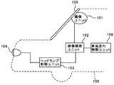
本実施形態の車載機器制御システムは、走行する移動体としての自車両100の進行方向前方領域を撮像領域として撮像する撮像ユニット101が設けられている。この撮像ユニット101は、例えば、自車両100のフロントガラス105のルームミラー(図示せず)付近に設置される。撮像ユニット101の撮像によって得られる撮像画像データ等の各種データは、画像処理手段としての画像解析ユニット102に入力される。画像解析ユニット102は、撮像ユニット101から送信されてくるデータを解析して、自車両100の前方に存在する他車両の位置、方角、距離を算出したり、自車両100が走行している路面(移動面)を検出したりする。他車両の検出では、他車両のテールランプを識別することで自車両100と同じ進行方向へ進行する先行車両を検出し、他車両のヘッドランプを識別することで自車両100とは反対方向へ進行する対向車両を検出する。
The in-vehicle device control system of the present embodiment is provided with an
画像解析ユニット102の算出結果は、ヘッドランプ制御ユニット103に送られる。ヘッドランプ制御ユニット103は、例えば、画像解析ユニット102が算出した他車両の距離データから、自車両100の車載機器であるヘッドランプ104を制御する制御信号を生成する。具体的には、例えば、先行車両や対向車両の運転者の目に自車両100のヘッドランプの強い光が入射するのを避けて他車両の運転者の幻惑防止を行いつつ、自車両100の運転者の視界確保を実現できるように、ヘッドランプ104のハイビームおよびロービームの切り替えを制御したり、ヘッドランプ104の部分的な遮光制御を行ったりする。
The calculation result of the
また、画像解析ユニット102の算出結果は、車両走行制御ユニット108にも送られる。車両走行制御ユニット108は、画像解析ユニット102が検出した路面領域(移動面画像領域)の認識結果に基づいて、路面領域から自車両100が外れそうな場合等に、自車両100の運転者へ警告を報知したり、自車両のハンドルやブレーキを制御するなどの走行支援制御を行ったりする。
The calculation result of the
図2は、撮像ユニット101及び画像解析ユニット102の概略構成を示す模式図である。
撮像ユニット101は、撮像手段としての2つの撮像部110A,110Bを備えたステレオカメラであり、2つの撮像部110A,110Bの構成は同一のものである。各撮像部110A,110Bは、それぞれ、撮像レンズ111A,111Bと、光学フィルタ112A,112Bと、撮像素子が2次元配置された画像センサ113A,113Bを含んだセンサ基板114A,114Bと、センサ基板114A,114Bから出力されるアナログ電気信号(画像センサ113A,113B上の各受光素子が受光した受光量)をデジタル電気信号に変換した撮像画像データを生成して出力する信号処理部115A,115Bとから構成されている。
FIG. 2 is a schematic diagram illustrating a schematic configuration of the
The
図3は、光学フィルタ112A,112Bと画像センサ113A,113Bとを光透過方向に対して直交する方向から見たときの模式拡大図である。
画像センサ113A,113Bは、CCD(Charge Coupled Device)やCMOS(Complementary Metal Oxide Semiconductor)などを用いたイメージセンサであり、その撮像素子(受光素子)にはフォトダイオード113aを用いている。フォトダイオード113aは、撮像画素ごとに2次元的にアレイ配置されており、フォトダイオード113aの集光効率を上げるために、各フォトダイオード113aの入射側にはマイクロレンズ113bが設けられている。この画像センサ113A,113Bがワイヤボンディングなどの手法によりPWB(printed wiring board)に接合されてセンサ基板114A,114Bが形成されている。
FIG. 3 is a schematic enlarged view when the
The
画像センサ113A,113Bのマイクロレンズ113b側の面には、光学フィルタ112A,112Bが近接配置されている。本実施形態の光学フィルタ112A,112Bは、図3に示すように、図示しない透明なフィルタ基板上に、偏光フィルタ層112aと分光フィルタ層112bとを形成したものである。偏光フィルタ層112a及び分光フィルタ層112bは、画像センサ113A,113B上における1つのフォトダイオード113aに対応するように領域分割されている。
光学フィルタ112A,112Bと画像センサ113A,113Bとの間に空隙がある構成としてもよいが、光学フィルタ112A,112Bを画像センサ113A,113Bに密着させる構成とした方が、光学フィルタ112A,112Bの各フィルタ領域の境界と画像センサ113A,113B上のフォトダイオード113a間の境界とを一致させやすくなる。光学フィルタ112A,112Bと画像センサ113A,113Bは、例えば、UV接着剤で接合してもよいし、撮像に用いる有効画素範囲外でスペーサにより支持した状態で有効画素外の四辺領域をUV接着や熱圧着してもよい。
The
図4は、本実施形態に係る光学フィルタ112A,112Bの領域分割パターンを示す説明図である。
光学フィルタ112A,112Bの偏光フィルタ層112aは、画像センサ113A,113B上の1つのフォトダイオード113a(一撮像画素)の縦列(鉛直方向)に平行に振動する垂直偏光成分(P偏光成分)のみを選択して透過させる垂直偏光領域と、画像センサ113A,113B上の1つのフォトダイオード113aの横列(水平方向)に平行に振動する水平偏光成分(S偏光成分)のみを選択して透過させる水平偏光領域とに領域分割されている。一方、光学フィルタ112A,112Bの分光フィルタ層112bは、赤色波長帯の光のみを選択して透過させる赤色分光領域と、波長選択を行わずに光を透過させる非分光領域とに領域分割されている。
FIG. 4 is an explanatory diagram showing a region division pattern of the
The
そして、光学フィルタ112A,112Bは、図4に示すように、偏光フィルタ層112aの垂直偏光領域及び分光フィルタ層112bの非分光領域を透過する第1領域112pcと、偏光フィルタ層112aの垂直偏光領域及び分光フィルタ層112bの赤色分光領域を透過する第2領域112prと、偏光フィルタ層112aの水平偏光領域及び分光フィルタ層112bの赤色分光領域を透過する第3領域112srと、偏光フィルタ層112aの水平偏光領域及び分光フィルタ層112bの非分光領域を透過する第4領域112scという4種類のフィルタ領域が、2×2の撮像画素に対応するように配置される。本実施形態では、画像センサ113A,113B上の2×2の撮像画素が、撮像画像上の1画素(以下「画像画素」という。)に対応する。
As shown in FIG. 4, the
その結果、本実施形態においては、第1領域112pcに対応する撮像画素の出力信号からp偏光非分光画像が得られ、第2領域112prに対応する撮像画素の出力信号からp偏光赤色画像が得られ、第3領域112srに対応する撮像画素の出力信号からs偏光赤色画像が得られ、第4領域112scに対応する撮像画素の出力信号からs偏光非分光画像が得られる。よって、本実施形態によれば、一度の撮像動作により、4種類の撮像画像データを得ることができる。これらの撮像画像データでは、その画像画素の数が撮像画素数の1/4となるが、より高解像度の画像を得る際には一般に知られる画像補間処理を用いてもよい。 As a result, in the present embodiment, a p-polarized non-spectral image is obtained from the output signal of the imaging pixel corresponding to the first region 112pc, and a p-polarized red image is obtained from the output signal of the imaging pixel corresponding to the second region 112pr. Thus, an s-polarized red image is obtained from the output signal of the imaging pixel corresponding to the third region 112sr, and an s-polarized non-spectral image is obtained from the output signal of the imaging pixel corresponding to the fourth region 112sc. Therefore, according to the present embodiment, four types of captured image data can be obtained by a single imaging operation. In these captured image data, the number of image pixels is 1/4 of the number of captured pixels, but generally known image interpolation processing may be used when obtaining a higher resolution image.
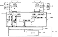
撮像ユニット101は、FPGA(Field-Programmable Gate Array)等からなる処理ハードウェア部120を備えている。この処理ハードウェア部120は、2つの撮像部110A,110Bから出力される4種類の撮像画像データに対する画像処理を施す画像データ処理部122A,122Bを備えている。
The
基準画像を撮像する撮像部110Aに対応する画像データ処理部122Aでは、撮像部110Aから出力されるp偏光赤色画像データとs偏光赤色画像データとから、赤色輝度画像データを生成する。具体的には、同一の画像画素(2×2の撮像画素)に対応するp偏光赤色画像の出力値とs偏光赤色画像の出力値との合計値を当該画像画素の画素値に対応づけた赤色輝度画像データを生成する。このようにして得られる赤色輝度画像データは、例えば、赤色に発光するテールランプの検出に使用することができる。
The image
また、画像データ処理部122Aは、撮像部110Aから出力されるp偏光非分光画像データとs偏光非分光画像データとから、非分光の輝度画像データを生成する。具体的には、同一の画像画素(2×2の撮像画素)に対応するp偏光非分光画像の出力値とs偏光非分光画像の出力値との合計値を当該画像画素の画素値に対応づけた非分光の輝度画像データを生成する。このようにして得られる非分光の輝度画像データは、例えば、車線境界線である白線、対向車両のヘッドランプの検出に使用することができる。
Further, the image
また、本実施形態において、2つの画像データ処理部122A,122Bは、指標値画像生成手段として機能し、撮像部110Aから出力されるp偏光非分光画像データとs偏光非分光画像データとから、p偏光成分とs偏光成分とに基づいて計算した指標値である差分偏光度に応じた画素値をもつ差分偏光度画像(指標値画像)データを生成する。具体的には、同一の画像画素(2×2の撮像画素)に対応するp偏光非分光画像の出力値とs偏光非分光画像の出力値とから差分偏光度を算出し、これを当該画像画素の画素値に対応づけた差分偏光度画像データを生成する。
In the present embodiment, the two image
差分偏光度は、下記の式(1)に示す計算式から求められる。すなわち、差分偏光度は、p偏光成分とs偏光成分との合計値に対するp偏光成分とs偏光成分との差分値の比率である。また、差分偏光度は、p偏光成分とs偏光成分との合計値に対するp偏光成分の比率と、p偏光成分とs偏光成分との合計値に対するs偏光成分の比率との差分値であると言い換えることもできる。本実施形態では、p偏光成分からs偏光成分を差し引く場合について説明するが、s偏光成分からp偏光成分を差し引くようにしてもよい。
差分偏光度=(p偏光成分−s偏光成分)/(p偏光成分+s偏光成分) ・・(1)
The differential polarization degree is obtained from the calculation formula shown in the following formula (1). That is, the differential polarization degree is the ratio of the difference value between the p-polarized component and the s-polarized component to the total value of the p-polarized component and the s-polarized component. The differential polarization degree is a difference value between the ratio of the p-polarized component to the total value of the p-polarized component and the s-polarized component and the ratio of the s-polarized component to the total value of the p-polarized component and the s-polarized component. In other words. In this embodiment, a case where the s-polarized component is subtracted from the p-polarized component will be described, but the p-polarized component may be subtracted from the s-polarized component.
Differential polarization degree = (p polarization component−s polarization component) / (p polarization component + s polarization component) (1)
指標値としては、p偏光成分とs偏光成分とを比較した指標値であるのが好ましく、本実施形態では、指標値として差分偏光度を使用する場合を例に挙げて説明するが、単純に、同一の画像画素(2×2の撮像画素)に対応するp偏光非分光画像の出力値とs偏光非分光画像の出力値との比率(偏光比)を指標値として用いてもよい。ただし、偏光比と差分偏光度とを比較すると、前者は、分母にくる偏光成分(例えばp偏光成分)がゼロ付近を示す場合には、偏光比は無限大に近づく値となってしまい、正確な値を得ることができない。一方、後者も、分母にくるp偏光成分とs偏光成分との合計値がゼロ付近を示す場合には、差分偏光度が無限大に近づく値となってしまい、正確な値を得ることができない。両者を比較したとき、後者の方が、分母がゼロ付近の値を取る確率が低く、正確な値を算出できる確率が高い。 The index value is preferably an index value obtained by comparing the p-polarized component and the s-polarized component. In the present embodiment, the case where the differential polarization degree is used as the index value will be described as an example. The ratio (polarization ratio) between the output value of the p-polarized non-spectral image and the output value of the s-polarized non-spectral image corresponding to the same image pixel (2 × 2 imaging pixels) may be used as the index value. However, when comparing the polarization ratio and the differential polarization degree, the former indicates that if the polarization component that comes to the denominator (for example, the p-polarization component) is near zero, the polarization ratio becomes a value that approaches infinity. Can not get a good value. On the other hand, in the latter case, if the total value of the p-polarized component and the s-polarized component coming to the denominator is near zero, the degree of differential polarization approaches infinity, and an accurate value cannot be obtained. . When comparing the two, the latter has a lower probability that the denominator takes a value near zero and has a higher probability of calculating an accurate value.
また、偏光比については、分母にくる偏光成分(例えばp偏光成分)がゼロ付近を示す場合には正確な値を算出できないが、分子にくる偏光成分(例えばs偏光成分)については、これがゼロ付近を示す場合でも正確な値を算出することが可能である。したがって、分子にくる偏光成分(例えばs偏光成分)を検出する場合に好適な指標値である。一方、差分偏光度は、分子にくるp偏光成分とs偏光成分との差分値がゼロ付近を示すのは、p偏光成分とs偏光成分がほぼ同じ値を示す場合である。p偏光成分がある値を示す確率とs偏光成分がそれと同じ値を示す確率は同等なので、差分偏光度は、p偏光成分もs偏光成分も平等に検出できる指標値であると言える。本実施形態では、以上の比較から、偏光比ではなく差分偏光度を指標値として用いる。 As for the polarization ratio, an accurate value cannot be calculated when the polarization component that comes to the denominator (for example, the p-polarization component) is near zero, but this is zero for the polarization component that comes to the numerator (for example, the s-polarization component). Even when the vicinity is shown, it is possible to calculate an accurate value. Therefore, it is an index value suitable for detecting a polarization component (for example, an s-polarization component) coming to a molecule. On the other hand, in the differential polarization degree, the difference value between the p-polarized component and the s-polarized component coming to the numerator shows a value near zero when the p-polarized component and the s-polarized component show almost the same value. Since the probability that the p-polarized light component has a certain value and the probability that the s-polarized light component has the same value are equal, the degree of differential polarization can be said to be an index value that can detect the p-polarized component and the s-polarized component equally. In the present embodiment, from the above comparison, not the polarization ratio but the differential polarization degree is used as the index value.
本実施形態の処理ハードウェア部120には、各撮像部110A,110Bで撮像した撮像画像について画像データ処理部122A,122Bで画像処理して得られた差分偏光度画像データから視差画像を得るために、両差分偏光度画像間の対応画像部分の視差値を演算する視差算出手段としての視差演算部121を備えている。ここでいう視差値とは、各撮像部110A,110Bでそれぞれ撮像した撮像画像の一方を基準画像、他方を比較画像とし、撮像領域内の同一地点に対応した基準画像上の画像部分(視差算出対象箇所)に対する比較画像上の画像部分(対応箇所)の位置ズレ量を、当該画像部分の視差値として算出したものである。三角測量の原理を利用することで、この視差値から当該画像部分に対応した撮像領域内の当該同一地点までの距離を算出することができる。
In the
本実施形態の視差演算部121で視差値を算出するために用いる基準画像と比較画像は、いずれも差分偏光度画像である。輝度画像から視差値を算出する場合、例えば撮像領域が暗くて輝度画像内に十分な輝度差が現れないような状況では、基準画像や比較画像上において画素値(輝度)特徴量に違いが出にくく、対応箇所の特定精度が悪いので、高精度な視差値を算出できない。これに対し、本実施形態のように、差分偏光度画像を基準画像及び比較画像として視差値を算出する場合には、十分な輝度差が得られない撮像状況下でも、基準画像や比較画像上において画素値(差分偏光度)特徴量に違いが出やすい。よって、本実施形態によれば、十分な輝度差が得られない撮像状況下でも、高精度な視差値を算出することが可能であるため、視差値を用いた移動面画像領域の認識処理を高精度に行うことができる。
The reference image and the comparison image used for calculating the parallax value by the
特に、路面からの反射光に含まれる偏光成分と、路面側端に位置する縁石等の段差、ガードレール、壁などの路面側端部材からの反射光に含まれる偏光成分とを比較すると、その反射面の向きがおよそ90度ほど異なることから、これらの偏光成分には大きな違いが出てくる。そのため、差分偏光度画像を用いることで、路面部分を映し出す路面画像領域と路面側端部材を映し出す画像領域との間で差分偏光度に大きな違いが出る結果、その路面画像領域のマッチング処理が適切に行われ、路面端部位置の適切な視差値が算出できる。 In particular, when the polarization component included in the reflected light from the road surface is compared with the polarization component included in the reflected light from the road surface side end members such as steps such as curbs, guardrails, and walls located at the road surface side end, the reflection Since the orientations of the planes differ by about 90 degrees, there is a great difference between these polarization components. For this reason, using the differential polarization degree image results in a large difference in the differential polarization degree between the road surface image area that shows the road surface portion and the image area that shows the road side end member, and matching processing of the road surface image area is appropriate. Thus, an appropriate parallax value of the road surface end position can be calculated.
画像解析ユニット102は、撮像ユニット101から出力される赤色輝度画像データ、輝度画像データ、差分偏光度画像データ、視差画像データを記憶するメモリ130と、識別対象物の認識処理や視差計算制御などを行うソフトウェアを内蔵したMPU(Micro Processing Unit)140とを備えている。MPU140は、メモリ130に格納された赤色輝度画像データ、輝度画像データ、差分偏光度画像データ、視差画像データを用いて各種の認識処理を実行する。
The
次に、本発明の特徴部分である、路面認識処理について説明する。
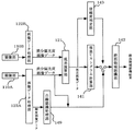
図5は、本実施形態の路面識処理に関わる機能ブロック図である。
図6は、本実施形態の路面識処理に関わるフローチャートである。
なお、図5に示す機能ブロック図の各処理ブロックで行われる処理は、専用のハードウェアを用いて処理してもいし、汎用の演算器を使用してソフトウェア処理により行ってもよい。本実施形態では、視差演算部121から視差画像データが出力された後の各処理ブロック141,142,143及び白線認識処理部149は、画像解析ユニット102のMPU140によるソフトウェア処理によって実現される。
Next, the road surface recognition process, which is a characteristic part of the present invention, will be described.
FIG. 5 is a functional block diagram related to road surface knowledge processing according to the present embodiment.
FIG. 6 is a flowchart related to the road surface knowledge processing of the present embodiment.
Note that the processing performed in each processing block of the functional block diagram shown in FIG. 5 may be performed using dedicated hardware, or may be performed by software processing using a general-purpose arithmetic unit. In the present embodiment, the processing blocks 141, 142, and 143 and the white line
本実施形態の視差演算部121は、2つの画像データ処理部122A,122Bのうちの一方から出力される差分偏光度画像データを基準画像データとし、他方から出力される差分偏光度画像データを比較画像データとして用い、両者の視差を演算して視差画像データを生成し、出力する。この視差画像データは、基準画像データ上の各画像部分について算出される視差値に応じた画素値をそれぞれの画像部分の画素値として表した視差画像を示すものである。
The
具体的には、ステップS10で画像データ処理部122A、122Bからそれぞれ入力された差分偏光画像を元に、視差演算部121は、基準画像データのある行について、一の注目画素を中心とした複数画素(例えば16画素×1画素)からなるブロックを定義する。一方、比較画像データにおける同じ行において、定義した基準画像データのブロックと同じサイズのブロックを1画素ずつ横ライン方向(X方向)へずらし、基準画像データにおいて定義したブロックの画素値の特徴を示す画素値特徴量と比較画像データにおける各ブロックの画素値の特徴を示す画素値特徴量との相関を示す相関値を、それぞれ算出する。そして、算出した相関値に基づき、比較画像データにおける各ブロックの中で最も基準画像データのブロックと相関があった比較画像データのブロックを選定するマッチング処理を行う。その後、基準画像データのブロックの注目画素と、マッチング処理で選定された比較画像データのブロックの対応画素との位置ズレ量を視差値として算出する(S11)。このような視差値を算出する処理を基準画像データの全域又は特定の一領域について行うことで、視差画像データを得ることができる。このようにして得られる視差画像データは、視差ヒストグラム情報生成手段としての視差ヒストグラム計算部141と、信頼度判定部143とに送られる。
Specifically, based on the differential polarization images respectively input from the image
マッチング処理に用いるブロックの特徴量としては、例えば、ブロック内の各画素の値(差分偏光度)を用いることができ、相関値としては、例えば、基準画像データのブロック内の各画素の値(差分偏光度)と、これらの画素にそれぞれ対応する比較画像データのブロック内の各画素の値(差分偏光度)との差分の絶対値の総和を用いることができる。この場合、当該総和が最も小さくなるブロックが最も相関があると言える。 As the feature amount of the block used for the matching process, for example, the value (difference polarization) of each pixel in the block can be used, and as the correlation value, for example, the value of each pixel in the block of the reference image data ( The sum of absolute values of differences between the difference polarization degree) and the value of each pixel (difference polarization degree) in the block of comparison image data corresponding to each of these pixels can be used. In this case, it can be said that the block having the smallest sum is most correlated.
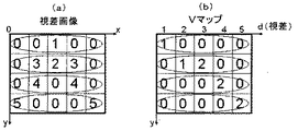
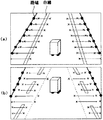
視差画像データを取得した視差ヒストグラム計算部141は、画像を上下方向に複数分割して得られる視差画像データの各行領域について、視差値頻度分布を計算する(S12)。この視差値頻度分布を示す情報が視差ヒストグラム情報である。具体例を挙げて説明すると、図7(a)に示すような視差値分布をもった視差画像データが入力されたとき、視差ヒストグラム計算部141は、行ごとの各視差値のデータの個数の分布である視差値頻度分布を計算し、これを視差ヒストグラム情報として出力する。このようにして得られる各行の視差値頻度分布の情報を、例えば、縦方向に視差画像上の縦方向位置をとり横方向に視差値をとった2次元平面上に表すことで、図7(b)に示すような行視差分布マップ(Vマップ)を得ることができる(S13)。路面領域を示す画素は、視差画像上の各行においてほぼ同一距離に存在して最も占有率が高く、かつ、画像上方へ向かうほど距離が連続的に遠くなる特徴をもっている。したがって、行視差分布マップ上において画像下部から上方へ向かうほど視差値が小さくなるような傾きをもった直線が、路面領域を表すこととなる。本実施形態では、これを利用して車両が走行可能な路面領域を検出する(S14)。
The parallax
図8(a)は、撮像部110Aで撮像した撮像画像(輝度画像)の一例を模式的に表した画像例であり、図8(b)は、視差ヒストグラム計算部141により算出される行ごとの視差値頻度分布から、行視差分布マップ(Vマップ)上の画素分布を直線近似したグラフである。
図8(a)に示す画像例は、中央分離帯を有する片側2車線の直線道路において自車両が左車線を走行している状況を撮像したものであり、図中符号CLは中央分離帯を映し出す中央分離帯画像部であり、図中符号WLは車線境界線である白線を映し出す白線画像部(車線境界線画像部)であり、図中符号ELは路端に存在する縁石等の段差を映し出す路端段差画像部である。以下、路端段差画像部EL及び中央分離帯段差画像部CLをまとめて段差画像部という。また、図中破線で囲まれた領域RSは、中央分離帯と路側段差とによって区画される車両走行が可能な路面領域(移動面画像領域)である。
FIG. 8A is an image example schematically showing an example of a captured image (luminance image) captured by the
The image example shown in FIG. 8A is an image of the situation where the host vehicle is traveling in the left lane on a straight road with two lanes on one side, and the reference sign CL in the figure indicates the center lane. This is a median strip image portion to be projected, and in the figure, a symbol WL is a white line image portion (lane border image portion) that projects a white line that is a lane boundary line, and a symbol EL in the drawing is a step such as a curb on the road edge. This is a road edge step image portion to be projected. Hereinafter, the road edge step image portion EL and the central separation band step image portion CL are collectively referred to as a step image portion. In addition, a region RS surrounded by a broken line in the drawing is a road surface region (moving surface image region) in which the vehicle can travel, which is partitioned by the median strip and the roadside step.
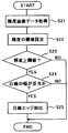
本実施形態では、信頼度判定部143が視差画像データの信頼度を判定し(S15)、これにより視差画像データの信頼度が規定値以上であれば(S16のYes)、路面領域認識部142において、視差ヒストグラム計算部141から出力される各行の視差値頻度分布の情報(視差ヒストグラム情報)から、路面領域RSを認識する(S17)。一方、視差画像データの信頼度が規定値未満であれば(S16のNo)、路面領域認識部142において、後述の白線認識処理部149により輝度画像データ及び差分偏光度画像データから認識される白線認識結果(S18)から、路面領域RSを認識する(S19)。
In the present embodiment, the
信頼度判定部143は、例えば、次のような方法で、視差画像データの信頼度を判定することができる。まず、入力された視差画像データ上で3×3画素のブロックを定義し、そのブロックを視差画像上下方向中央において左端から右端までずらしていき、各ブロック内の画素値(視差値)の分散を算出する。そして、各ブロックの分散の合計値を信頼度として用い、その合計値が規定数未満である場合には当該視差画像データの信頼度が高い(規定値以上である)と判断し、その合計値が規定数以上である場合には当該視差画像データの信頼度が低い(規定値未満である)と判断する。なお、この処理において各ブロック内に映し出される物体は、自車両から同一距離にある物体であることが多いので、適正な視差値が算出されていれば各ブロックの分散は小さな値をとるが、適正な視差値が算出されていない場合には各ブロックの分散は大きな値をとることになる。本実施形態の信頼度判定部143は、この違いを見ることで、視差画像データの信頼度を判定する。
上記のような信頼度判定方法の他、照度自体の高低、輝度のコントラストの大小などを用いることによって、信頼度の判定を行っても良い。
For example, the
In addition to the reliability determination method as described above, the reliability may be determined by using the level of illuminance itself, the magnitude of brightness contrast, and the like.
信頼度判定部143において視差画像データの信頼度が高い(規定値以上である)と判定された場合、路面領域認識部142には、視差ヒストグラム計算部141から出力される各行の視差値頻度分布情報が入力される。これを取得した路面領域認識部142は、その入力情報から特定される行視差分布マップ上の画素分布を最小二乗法やハフ変換処理などにより直線近似する処理を行う。このとき、直線近似する視差値範囲を、例えば実距離20mに相当する視差値範囲ごとに区分し、各区分の視差値範囲内でそれぞれ直線近似する処理を行うのが好ましい。
When the
撮像画像内に映し出される路面の傾斜状況が途中で変化するような場合(例えば平坦から急な上り坂に変化する場合)、行視差分布マップ上の路面領域に対応する画素の分布は、傾斜状況が変化する地点に対応する箇所で、画像上下方向位置変化に対する路面領域の視差値変化(傾き)が変化する。そのため、この場合、行視差分布マップの全域で画素分布を直線近似すると、路面領域を適切に認識することができないおそれがある。これに対し、直線近似する視差値範囲を上述したように複数に区分し、各区分の視差値範囲内でそれぞれ直線近似する処理を行えば、路面の傾斜状況が途中で変化する状況下でも、その傾き変化に対応して近似できるため、路面領域を適切に認識することができる。 When the road slope displayed in the captured image changes midway (for example, when it changes from flat to a steep uphill), the distribution of pixels corresponding to the road surface area on the line parallax distribution map The change (gradient) in the parallax value of the road surface region with respect to the change in the vertical position of the image changes at a location corresponding to the location where the change occurs. Therefore, in this case, if the pixel distribution is linearly approximated across the entire row parallax distribution map, the road surface area may not be recognized properly. On the other hand, if the parallax value range to be linearly approximated is divided into a plurality as described above, and the process of linearly approximating each within the parallax value range of each category is performed, even under the situation where the slope condition of the road surface changes in the middle, Since it can be approximated corresponding to the change in inclination, the road surface area can be appropriately recognized.
これにより得られる近似直線は、図8(b)に示すように、視差画像の下部に対応する行視差分布マップの下部において、画像上方へ向かうほど視差値が小さくなるような傾きをもった直線となる。すなわち、この近似直線上又はその近傍に分布する画素(視差画像上の画素)は、視差画像上の各行においてほぼ同一距離に存在して最も占有率が高く、かつ、画像上方へ向かうほど距離が連続的に遠くなる対象を映し出した画素であると言える。 As shown in FIG. 8B, the approximate straight line thus obtained is a straight line having an inclination such that the parallax value becomes smaller toward the upper part of the image at the lower part of the row parallax distribution map corresponding to the lower part of the parallax image. It becomes. That is, pixels distributed on or near the approximate line (pixels on the parallax image) are present at almost the same distance in each row on the parallax image, have the highest occupancy, and the distance increases toward the top of the image. It can be said that it is a pixel that projects objects that are continuously distant.
ここで、撮像部110Aでは自車両前方領域を撮像するため、その視差画像の内容は、図8(a)に示すように、画像下部において路面領域RSの占有率が最も高く、また、画像上方へ向かうほど路面領域RSの視差値は小さくなる。また、同じ行(横ライン)内において、路面領域RSを構成する画素はほぼ同じ視差値を持つことになる。したがって、視差ヒストグラム計算部141から出力される各行の視差値頻度分布情報から特定される、上述した行視差分布マップ(Vマップ)上の近似直線上又はその近傍に分布する画素は、路面領域RSを構成する画素が持つ特徴に合致する。よって、図8(b)に示す近似直線上又はその近傍に分布する画素は、高い精度で、路面領域RSを構成する画素であると推定できる。
Here, since the
このように、本実施形態の路面領域認識部142は、視差ヒストグラム計算部141から得た各行の視差値頻度分布情報に基づいて演算した行視差分布マップ(Vマップ)上の直線近似を行い、その近似直線上又はその近傍に分布する画素を、路面を映し出す画素として特定し、特定した画素によって占められる画像領域を路面領域RSとして認識する。なお、路面上には図8(a)に示すように白線も存在するが、路面領域認識部142では、白線画像部WLも含めて路面領域RSを認識する。
As described above, the road surface
一方、信頼度判定部143において視差画像データの信頼度が低い(規定値未満である)と判定された場合、路面領域認識部142には、白線認識処理部149から出力される白線認識結果と画像データ処理部122Aから出力される差分偏光度画像データとが入力される。
On the other hand, when the
白線認識処理部149は、画像データ処理部122Aから輝度画像データを取得したら、まず、輝度画像データについて、画素値(輝度)が規定値以上変化する箇所をエッジ部分として抽出する。エッジ抽出の方法は、公知のものを広く利用することができる。多くの道路では、黒色に近い色の路面上に白線が形成されており、輝度画像上において白線画像部WLの輝度は路面上の他部分より十分に大きい。そのため、輝度画像上で所定値以上の画素値の差を有するエッジ部は、白線のエッジ部である可能性が高い。また、路面上の白線を映し出す白線画像部WLは、撮像画像上においてライン状に映し出されるので、ライン状に並ぶエッジ部を特定することで、白線のエッジ部を高精度に認識することができる。よって、本実施形態の白線認識処理部149は、エッジ部分について最小二乗法やハフ変換処理などによる直線近似処理を施し、得られた近似直線を白線のエッジ部(路面上の白線を映し出す白線画像部WL)として認識する。
When the white line
図9は、白線認識処理の一例を示すフローチャートである。
本例においては、画像データ処理部122Aから輝度画像データを取得したら(S21)、まず、輝度の閾値を設定する(S22)。このとき、画像上方と下方とでは、白線のコントラストが違っているため、同一の閾値を用いて処理を行うと、良好な結果が得られない場合がある。そのような場合には、1つの画像を上方と下方の2つのエリアを分け、それぞれに適用する輝度の閾値を個別に設定する。このようにして設定される輝度の閾値を用いて、輝度画像データの各画素値(輝度)と当該閾値との大小比較を行う(S23)。この大小比較により閾値以上の輝度をもつ画素を白線エッジの候補点として検出する。その後、検出された白線エッジの候補点と、予め定められた白線幅の閾値との大小比較を行って、検出された白線エッジの候補点による白線幅が妥当か否かを判断する(S24)。この判断において妥当であると判断された場合、検出された白線エッジの候補点を、1本の白線の両端エッジを示す一対の白線エッジ部として抽出する。
FIG. 9 is a flowchart illustrating an example of white line recognition processing.
In this example, when luminance image data is acquired from the image
路面領域認識部142は、白線認識処理部149から出力される白線認識結果と、画像データ処理部122Aから出力される差分偏光度画像データとが入力されると、次のような処理を行う。まず、白線認識結果に基づき、差分偏光度画像データ上の白線画像部に対応する地点を特定し、その白線画像部の画像中央側に近接する画素(路面基準画素)の画素値(差分偏光度)を取得する。この路面基準画素は、一般に、路面を映し出したものである可能性が高いので、この路面基準画素の差分偏光度は、現状における路面の差分偏光度を示すものであると推定することができる。
When the white line recognition result output from the white line
次に、路面領域認識部142は、差分偏光度画像データの各行について、白線画像部から画像左右方向外側に向かって例えば1画素ずつ対象画素をずらし、各対象画素の差分偏光度と路面基準画素の差分偏光度との差分値を算出していく。対象画素が路面を映し出すものであれば、その対象画素の差分偏光度と路面基準画素の差分偏光度とはほぼ同じ値をとる。一方、対象画素が路端に存在する縁石等の段差、壁などの路面側端部材を映し出すものであれば、その対象画素の差分偏光度は、路面基準画素の差分偏光度とは大きく異なる値をとる。よって、路面領域認識部142は、各対象画素の差分偏光度と路面基準画素の差分偏光度との差分値を算出していき、その差分値が所定の閾値を超える箇所が現れたら、その箇所が路面と路面側端部材との境界に対応すると判断し、その判断結果から路面領域を認識する。
Next, the road surface
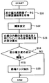
図10は、路面領域認識処理の一例を示すフローチャートである。
本例においては、白線認識処理部149から出力される白線認識結果と、画像データ処理部122Aから出力される差分偏光度画像データとを取得したら(S31)、閾値を設定した後に(S32)、上述した処理を行う。すなわち、白線認識結果に基づき、差分偏光度画像データ上の白線画像部に対応する地点を特定し、差分偏光度画像データの各行(ライン)について、その白線画像部の画像中央側(内側)に近接する画素(路面基準画素)の画素値(差分偏光度)を取得する。その後、差分偏光度画像データの各行(ライン)について、白線画像部から画像左右方向外側に向かって例えば1画素ずつ対象画素をずらし、各対象画素の差分偏光度と路面基準画素の差分偏光度との差分値を算出していく(S33)。対象画素が路面を映し出すものであれば、その対象画素の差分偏光度と路面基準画素の差分偏光度とはほぼ同じ値をとるが、対象画素が路端に存在する縁石等の段差、壁などの路面側端部材を映し出すものであれば、その対象画素の差分偏光度は、路面基準画素の差分偏光度とは大きく異なる値をとる。したがって、各対象画素の差分偏光度と路面基準画素の差分偏光度との差分値を算出していき、その差分値が閾値を超える箇所が現れたら(S34)、その箇所が路面と路面側端部材との境界(路端エッジ)に対応すると判断し、その対象画素を路端エッジとして抽出する(S35)。
FIG. 10 is a flowchart illustrating an example of a road surface area recognition process.
In this example, after obtaining the white line recognition result output from the white line
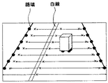
図11は、白線認識結果の一例に対応した路面領域認識処理の内容を説明するための説明図である。
本例では、2本の白線が映し出されている撮像画像において、それらの白線に対応する白線エッジ部が適切に抽出された例である。この場合、上述したとおり、差分偏光度画像データの各行(ライン)について、白線画像部から画像左右方向外側に向かって、白線内側の路面基準画素の差分偏光度と白線外側の各対象画素の差分偏光度との差分値を算出していき、その差分値を閾値と比較することで、路端エッジを抽出する。なお、図11において、図中「×」で示す箇所は、路面基準画素の差分偏光度との差分値が閾値未満である対象画素を示し、当該差分値が閾値以上となった対象画素は「●」で示してある。したがって、「●」で示す画素を結んだ線が路端エッジを示すものと認識される。
FIG. 11 is an explanatory diagram for explaining the contents of the road surface area recognition process corresponding to an example of the white line recognition result.
In this example, in the captured image in which two white lines are projected, white line edge portions corresponding to the white lines are appropriately extracted. In this case, as described above, with respect to each row (line) of the differential polarization degree image data, the difference between the differential polarization degree of the road surface reference pixel inside the white line and the target pixel outside the white line from the white line image portion toward the outside in the horizontal direction of the image. A difference value with the degree of polarization is calculated, and the road edge is extracted by comparing the difference value with a threshold value. In FIG. 11, a portion indicated by “x” in the figure indicates a target pixel whose difference value from the differential polarization degree of the road surface reference pixel is less than the threshold value, and the target pixel whose difference value is equal to or greater than the threshold value is “ ● ”. Therefore, a line connecting pixels indicated by “●” is recognized as indicating a road edge.
図12は、白線認識結果の他の例に対応した路面領域認識処理の内容を説明するための説明図である。
本例では、画像左側部分に1本の白線が映し出されている撮像画像において、その白線に対応する白線エッジ部が適切に抽出された例である。この場合、画像左側の路端エッジについては、認識された白線画像部から画像左側に向かって、白線内側の路面基準画素の差分偏光度と白線外側の各対象画素の差分偏光度との差分値を算出していき、その差分値を閾値と比較することで、路端エッジを抽出する。一方、画像右側の路端エッジについては、認識された白線画像部から画像右側に向かって、路面基準画素の差分偏光度と白線外側の各対象画素の差分偏光度との差分値を算出していき、その差分値を閾値と比較することで、路端エッジを抽出する。このときの路面基準画素は、画像左側の路端エッジの抽出時に用いる路面基準画素と同じものを用いる。
FIG. 12 is an explanatory diagram for explaining the contents of the road surface area recognition process corresponding to another example of the white line recognition result.
In this example, in the captured image in which one white line is projected on the left side of the image, a white line edge portion corresponding to the white line is appropriately extracted. In this case, for the road edge on the left side of the image, from the recognized white line image portion toward the left side of the image, the difference value between the differential polarization degree of the road surface reference pixel inside the white line and the differential polarization degree of each target pixel outside the white line And the road edge is extracted by comparing the difference value with a threshold value. On the other hand, for the road edge on the right side of the image, the difference value between the difference polarization degree of the road surface reference pixel and the difference polarization degree of each target pixel outside the white line is calculated from the recognized white line image portion to the right side of the image. Then, the road edge is extracted by comparing the difference value with a threshold value. The road surface reference pixels at this time are the same as the road surface reference pixels used when extracting the road edge on the left side of the image.
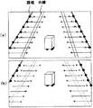
図13(a)及び(b)は、白線認識結果の更に他の例に対応した路面領域認識処理の内容を説明するための説明図である。
本例では、前回の撮像画像(フレーム)では図13(a)に示すように2本の白線が適切に抽出できていたが、今回の撮像画像(フレーム)では図13(b)に示すように2本の白線がいずれも抽出できなかった例である。この場合、今回の撮像画像についての路端エッジの抽出には、前回の撮像画像における白線認識結果(図13(b)中破線で示す。)を用いる。すなわち、差分偏光度画像データの各行(ライン)について、前回の撮像画像で認識された白線画像部から画像左右方向外側に向かって、白線内側の路面基準画素の差分偏光度と白線外側の各対象画素の差分偏光度との差分値を算出していき、その差分値を閾値と比較することで、路端エッジを抽出する。
FIGS. 13A and 13B are explanatory diagrams for explaining the contents of the road surface area recognition process corresponding to still another example of the white line recognition result.
In this example, in the previous captured image (frame), two white lines were appropriately extracted as shown in FIG. 13A, but in the current captured image (frame), as shown in FIG. 13B. In this example, neither of the two white lines could be extracted. In this case, the extraction of the road edge for the current captured image uses the white line recognition result (shown by the broken line in FIG. 13B) in the previous captured image. That is, for each row (line) of differential polarization degree image data, from the white line image portion recognized in the previous captured image, outward in the horizontal direction of the image, the differential polarization degree of the road surface reference pixel inside the white line and each object outside the white line A difference value from the differential polarization degree of the pixel is calculated, and the road edge is extracted by comparing the difference value with a threshold value.
図14(a)及び(b)は、白線認識結果の更に他の例に対応した路面領域認識処理の内容を説明するための説明図である。
本例では、前回の撮像画像(フレーム)でも図14(a)に示すように白線エッジ部が抽出されず、かつ、今回の撮像画像(フレーム)でも図14(b)に示すように白線エッジ部が抽出されなかった例である。この場合、差分偏光度画像データの各行(ライン)について、画像左右方向中央の画素を路面基準画素とし、画像左右方向中央から画像左右方向両側に向かって、当該路面基準画素の差分偏光度と各対象画素の差分偏光度との差分値を算出していき、その差分値を閾値と比較することで、路端エッジを抽出する。
FIGS. 14A and 14B are explanatory diagrams for explaining the contents of road surface area recognition processing corresponding to still another example of the white line recognition result.
In this example, the white line edge portion is not extracted in the previous captured image (frame) as shown in FIG. 14A, and the white line edge is also extracted in the current captured image (frame) as shown in FIG. 14B. This is an example in which no part was extracted. In this case, for each row (line) of the differential polarization degree image data, the pixel in the center in the left-right direction of the image is used as a road surface reference pixel, and the differential polarization degree of the road surface reference pixel and each A road edge is extracted by calculating a difference value with the differential polarization degree of the target pixel and comparing the difference value with a threshold value.
図15(a)及び(b)は、白線認識結果の更に他の例に対応した路面領域認識処理の内容を説明するための説明図である。
本例では、前回の撮像画像(フレーム)では図15(a)に示すように連続的な白線エッジ部が抽出されていたが、今回の撮像画像(フレーム)では図15(b)に示すように断続的な白線エッジ部が抽出された例である。この場合、白線エッジ部が抽出されている行(ライン)については、その白線画像部から画像左右方向外側に向かって、白線内側の路面基準画素の差分偏光度と白線外側の各対象画素の差分偏光度との差分値を算出していき、その差分値を閾値と比較することで、路端エッジを抽出する。一方、白線エッジ部が抽出されていない行(ライン)については、前回の撮像画像における白線認識結果(図15(b)中破線で示す。)を用い、前回の撮像画像で認識された白線画像部から画像左右方向外側に向かって、白線内側の路面基準画素の差分偏光度と白線外側の各対象画素の差分偏光度との差分値を算出していき、その差分値を閾値と比較することで、路端エッジを抽出する。
FIGS. 15A and 15B are explanatory diagrams for explaining the contents of road surface area recognition processing corresponding to still another example of the white line recognition result.
In this example, a continuous white line edge portion was extracted as shown in FIG. 15A in the previous captured image (frame), but as shown in FIG. 15B in the current captured image (frame). In this example, intermittent white line edge portions are extracted. In this case, with respect to the row (line) from which the white line edge portion is extracted, from the white line image portion toward the outer side in the left-right direction of the image, the difference in polarization degree of the road surface reference pixel inside the white line and the difference between each target pixel outside the white line A difference value with the degree of polarization is calculated, and the road edge is extracted by comparing the difference value with a threshold value. On the other hand, for a line (line) from which no white line edge portion has been extracted, the white line image recognized in the previous captured image using the white line recognition result in the previous captured image (indicated by a broken line in FIG. 15B). Calculating the difference value between the difference polarization degree of the road surface reference pixel inside the white line and the difference polarization degree of each target pixel outside the white line, and comparing the difference value with a threshold value Then, the road edge is extracted.
図16(a)及び(b)は、白線認識結果の更に他の例に対応した路面領域認識処理の内容を説明するための説明図である。
本例では、前回の撮像画像(フレーム)では図16(a)に示すように白線エッジ部が抽出されず、今回の撮像画像(フレーム)では連続的な白線エッジ部が一部だけ抽出されている例である。この場合、白線エッジ部が抽出されている行(ライン)については、その白線画像部から画像左右方向外側に向かって、白線内側の路面基準画素の差分偏光度と白線外側の各対象画素の差分偏光度との差分値を算出していき、その差分値を閾値と比較することで、路端エッジを抽出する。一方、白線エッジ部が抽出されていない行(ライン)については、今回の撮像画像で抽出された白線エッジ部を延長した仮想の白線エッジ部(図16(b)中破線で示す。)を用い、当該仮想の白線エッジ部によって特定される白線画像部から画像左右方向外側に向かって、白線内側の路面基準画素の差分偏光度と白線外側の各対象画素の差分偏光度との差分値を算出していき、その差分値を閾値と比較することで、路端エッジを抽出する。
FIGS. 16A and 16B are explanatory diagrams for explaining the contents of road surface area recognition processing corresponding to still another example of the white line recognition result.
In this example, the white line edge portion is not extracted from the previous captured image (frame) as shown in FIG. 16A, and only a part of the continuous white line edge portion is extracted from the current captured image (frame). This is an example. In this case, with respect to the row (line) from which the white line edge portion is extracted, from the white line image portion toward the outer side in the left-right direction of the image, the difference in polarization degree of the road surface reference pixel inside the white line and the difference between each target pixel outside the white line A difference value with the degree of polarization is calculated, and the road edge is extracted by comparing the difference value with a threshold value. On the other hand, for a line (line) from which no white line edge portion is extracted, a virtual white line edge portion (indicated by a broken line in FIG. 16B) obtained by extending the white line edge portion extracted from the current captured image is used. From the white line image portion specified by the virtual white line edge portion, the difference value between the differential polarization degree of the road surface reference pixel inside the white line and the differential polarization degree of each target pixel outside the white line is calculated outward in the horizontal direction of the image. Then, the road edge is extracted by comparing the difference value with a threshold value.
路面領域認識部142の認識結果は、後段の処理部に送られ、種々の処理に使用される。例えば、撮像ユニット101で撮像した自車両前方の撮像画像を例えば自車両室内の画像表示装置に表示する場合、路面領域認識部142の認識結果に基づき、その表示画像上の対応する路面領域RSを強調表示するなど、路面領域RSが視認しやすい表示処理を行う。
The recognition result of the road surface
以上に説明したものは一例であり、本発明は、次の態様毎に特有の効果を奏する。
(態様A)
路面等の移動面上を移動する自車両100等の移動体に搭載された2つの撮像部110A,110B等の複数の撮像手段により移動体周囲の撮像領域を撮像して得られる複数の撮像画像の1つである基準画像上で視差算出対象箇所を設定し、設定した視差算出対象箇所についての画素値特徴量と一致し又は所定の近似範囲内に含まれる画素値特徴量を有する対応箇所を、他の撮像画像である比較画像内から特定し、特定した対応箇所と当該視差算出対象箇所との視差値を算出する視差演算部121等の視差算出手段と、上記視差算出手段の算出結果に基づいて、上記撮像手段により撮像した撮像画像内の上記移動面を映し出す路面領域RS等の移動面画像領域を認識する処理を行う路面領域認識部142等の移動面認識処理手段とを有する移動面認識装置であって、上記撮像手段が撮像した撮像画像から、偏光方向が互いに異なる複数の偏光成分(p偏光成分とs偏光成分)に基づいて計算した差分偏光度等の指標値に応じた画素値をもつ差分偏光度画像等の指標値画像を生成する画像データ処理部122A,122B等の指標値画像生成手段を有し、上記視差算出手段は、上記基準画像及び上記比較画像として、上記指標値画像生成手段により生成される指標値画像を用いて、上記視差値を算出することを特徴とする。
視差値を用いて移動面画像領域を高い精度で認識するためには、その視差値の精度が重要となる。視差値の精度を高めるには、基準画像上に設定した視差算出対象箇所についての画素値特徴量と一致し又は所定の近似範囲内に含まれる画素値特徴量を有する対応箇所を比較画像内から高精度に特定することが必要となる。このとき、輝度画像から視差値を算出する場合、例えば撮像領域が暗くて輝度画像内に十分な輝度差が現れないような状況では、基準画像や比較画像上において画素値特徴量に違いが出にくく、対応箇所の特定精度が悪いので、高精度な視差値を算出できない。これに対し、本態様のように、偏光方向が互いに異なる複数の偏光成分に基づいて計算した指標値に応じた画素値をもつ指標値画像を基準画像及び比較画像として視差値を算出する場合には、十分な輝度差が得られない撮像状況下でも、基準画像や比較画像上において画素値特徴量に違いが出やすい。よって、本態様によれば、十分な輝度差が得られない撮像状況下でも、高精度な視差値を算出することが可能であるため、視差値を用いた移動面画像領域の認識処理を高精度に行うことができる。
What has been described above is merely an example, and the present invention has a specific effect for each of the following modes.
(Aspect A)
A plurality of captured images obtained by imaging an imaging region around the moving body by a plurality of imaging means such as two
In order to recognize the moving plane image area with high accuracy using the parallax value, the accuracy of the parallax value is important. In order to increase the accuracy of the parallax value, a corresponding location having a pixel value feature amount that matches the pixel value feature amount of the parallax calculation target location set on the reference image or is included in a predetermined approximate range is selected from the comparison image. It is necessary to specify with high accuracy. At this time, when calculating the parallax value from the luminance image, for example, in a situation where the imaging region is dark and a sufficient luminance difference does not appear in the luminance image, a difference appears in the pixel value feature amount on the reference image or the comparison image. It is difficult to calculate the parallax value with high accuracy because the identification accuracy of the corresponding portion is poor. On the other hand, when the parallax value is calculated using the index value image having the pixel value corresponding to the index value calculated based on a plurality of polarization components having different polarization directions as the reference image and the comparison image, as in this aspect. However, even in an imaging situation where a sufficient luminance difference cannot be obtained, the pixel value feature amount is likely to be different on the reference image or the comparison image. Therefore, according to this aspect, it is possible to calculate a highly accurate parallax value even under an imaging situation where a sufficient luminance difference cannot be obtained. Can be done with precision.
(態様B)
上記態様Aにおいて、上記視差算出手段が算出した視差値に基づいて、上記撮像画像を上下方向に複数分割して得られる各行領域内における視差値の頻度分布を示す視差ヒストグラム情報を生成する視差ヒストグラム計算部141等の視差ヒストグラム情報生成手段を有し、上記移動面認識処理手段は、上記視差ヒストグラム情報に基づいて、予め決められた規定値を超える頻度をもった視差値又は視差値範囲の中から、上記撮像画像の上方に向かうほど値が低くなるという特徴に合致した一群の視差値又は視差値範囲を選別し、選別した一群の視差値又は視差値範囲に対応する上記撮像画像上の画素が属する画像領域を、上記移動面画像領域として認識する処理を行うことを特徴とする。
これによれば、移動面画像領域の認識処理を簡易かつ高精度に行うことができる。
(Aspect B)
In the aspect A, based on the parallax value calculated by the parallax calculation unit, the parallax histogram that generates parallax histogram information indicating the frequency distribution of the parallax values in each row region obtained by dividing the captured image into a plurality of vertical directions. A parallax histogram information generating unit such as a
According to this, the recognition process of the moving surface image area can be performed easily and with high accuracy.
(態様C)
上記態様Bにおいて、上記移動面認識処理手段は、予め決められた規定値を超える頻度をもった視差値又は視差値範囲をその視差値に応じて複数に区分し、区分ごとに当該視差値又は視差値範囲を上記撮像画像の上方に向かうほど一定の割合で視差値が低くなるように近似処理し、近似処理した一群の視差値又は視差値範囲を上記特徴に合致した一群の視差値又は視差値範囲として選別することを特徴とする。
これによれば、路面の傾斜状況が途中で変化しているような路面画像領域についても、精度よく認識することができる。
(Aspect C)
In the aspect B, the moving surface recognition processing unit divides a parallax value or a parallax value range having a frequency exceeding a predetermined specified value into a plurality according to the parallax value, and the parallax value or The parallax value range is approximated so that the parallax value decreases at a constant rate as it goes above the captured image. It is characterized by sorting as a value range.
According to this, it is possible to accurately recognize a road surface image region in which the road surface inclination state changes midway.
(態様D)
上記A〜Cのいずれかの態様において、上記基準画像を撮像する撮像部110A等の撮像手段により撮像した撮像画像から上記指標値画像生成手段が生成した指標値画像の画素値が規定値以上変化する箇所をエッジ箇所として抽出し、その抽出結果に基づいて上記移動面画像領域の候補領域を検出する路面領域認識部142等の候補領域検出手段を有し、上記移動面認識処理手段は、上記候補領域検出手段の検出結果と上記視差算出手段の算出結果とに基づいて上記移動面画像領域を認識する処理を行うことを特徴とする。
これによれば、視差算出手段の算出結果だけでなく、指標値画像のエッジ箇所の抽出結果も用いて、移動面画像領域を認識することができるので、高精度な認識結果をより安定して提供することが可能である。
(Aspect D)
In any one of the aspects A to C, the pixel value of the index value image generated by the index value image generating unit from the captured image captured by the imaging unit such as the
According to this, since the moving surface image area can be recognized not only using the calculation result of the parallax calculation means but also the extraction result of the edge portion of the index value image, the highly accurate recognition result can be more stably performed. It is possible to provide.
(態様E)
上記態様Dにおいて、基準画像上の視差算出対象箇所に対応して特定された比較画像上の対応箇所の特定精度に応じて、上記視差算出手段の算出結果の信頼度を決定する信頼度判定部143等の視差値信頼度決定手段を有し、上記移動面認識処理手段は、上記視差値信頼度決定手段が決定した信頼度が規定条件を満たすときは、上記視差算出手段の算出結果に基づいて上記移動面画像領域を認識し、該信頼度が該規定条件を満たさないときは、上記候補領域検出手段の検出結果に基づいて上記移動面画像領域を認識する処理を行うことを特徴とする。
これによれば、より精度の高い認識結果を安定して提供することが可能となる。
(Aspect E)
In the aspect D, a reliability determination unit that determines the reliability of the calculation result of the parallax calculation unit according to the identification accuracy of the corresponding position on the comparison image specified corresponding to the parallax calculation target position on the
According to this, it becomes possible to provide a more accurate recognition result stably.
(態様F)
上記態様A〜Eのいずれかの態様において、上記撮像手段を備えていることを特徴とする。
これによれば、移動面認識装置を車両に設置する用途に使用することができる。
(Aspect F)
In any one of the aspects A to E, the imaging unit is provided.
According to this, it can be used for the use which installs a moving surface recognition apparatus in a vehicle.
(態様G)
移動面上を移動する移動体に搭載された複数の撮像手段により移動体周囲の撮像領域を撮像して得られる複数の撮像画像の1つである基準画像上で視差算出対象箇所を設定し、設定した視差算出対象箇所についての画素値特徴量と一致し又は所定の近似範囲内に含まれる画素値特徴量を有する対応箇所を、他の撮像画像である比較画像内から特定し、特定した対応箇所と当該視差算出対象箇所との視差値を算出する視差算出工程と、上記視差算出工程の算出結果に基づいて、上記撮像手段により撮像した撮像画像内の上記移動面を映し出す移動面画像領域を認識する処理を行う移動面認識処理工程とを有する移動面認識方法であって、上記撮像手段が撮像した撮像画像から、偏光方向が互いに異なる複数の偏光成分に基づいて計算した指標値に応じた画素値をもつ指標値画像を生成する指標値画像生成工程を有し、上記視差算出工程では、上記基準画像及び上記比較画像として、上記指標値画像生成手段により生成される指標値画像を用いて、上記視差値を算出することを特徴とする。
これによれば、十分な輝度差が得られない撮像状況下でも、高精度な視差値を算出することが可能であるため、視差値を用いた移動面画像領域の認識処理を高精度に行うことができる。
(Aspect G)
A parallax calculation target location is set on a reference image which is one of a plurality of captured images obtained by imaging an imaging region around the moving body by a plurality of imaging units mounted on the moving body moving on the moving surface; A corresponding location that matches the pixel value feature amount of the set parallax calculation target location or has a pixel value feature amount included in a predetermined approximate range is identified from the comparison image that is another captured image, and the identified correspondence A parallax calculation step of calculating a parallax value between the location and the parallax calculation target location, and a moving plane image region that displays the moving plane in the captured image captured by the imaging unit based on the calculation result of the parallax calculation step A moving surface recognition method including a moving surface recognition processing step for performing recognition processing, wherein the index value is calculated based on a plurality of polarization components having different polarization directions from a captured image captured by the imaging unit. An index value image generating step for generating an index value image having a corresponding pixel value. In the parallax calculating step, the index value image generated by the index value image generating means is used as the reference image and the comparison image. And calculating the parallax value.
According to this, since it is possible to calculate a highly accurate parallax value even under an imaging situation in which a sufficient luminance difference cannot be obtained, the recognition process of the moving plane image region using the parallax value is performed with high accuracy. be able to.
(態様H)
移動面上を移動する移動体に搭載された複数の撮像手段により移動体周囲の撮像領域を撮像して得られる複数の撮像画像の1つである基準画像上で視差算出対象箇所を設定し、設定した視差算出対象箇所についての画素値特徴量と一致し又は所定の近似範囲内に含まれる画素値特徴量を有する対応箇所を、他の撮像画像である比較画像内から特定し、特定した対応箇所と当該視差算出対象箇所との視差値を算出する視差算出工程と、上記視差算出工程の算出結果に基づいて、上記撮像手段により撮像した撮像画像内の上記移動面を映し出す移動面画像領域を認識する処理を行う移動面認識処理工程とを、コンピュータに実行させるための移動面認識用プログラムであって、上記撮像手段が撮像した撮像画像から、偏光方向が互いに異なる複数の偏光成分に基づいて計算した指標値に応じた画素値をもつ指標値画像を生成する指標値画像生成工程を上記コンピュータに実行させるものであって、上記視差算出工程では、上記基準画像及び上記比較画像として、上記指標値画像生成手段により生成される指標値画像を用いて、上記視差値を算出することを特徴とする。
これによれば、十分な輝度差が得られない撮像状況下でも、高精度な視差値を算出することが可能であるため、視差値を用いた移動面画像領域の認識処理を高精度に行うことができる。
尚、このプログラムは、CD−ROM等の記録媒体に記録された状態で配布したり、入手したりすることができる。また、このプログラムを乗せ、所定の送信装置により送信された信号を、公衆電話回線や専用線、その他の通信網等の伝送媒体を介して配信したり、受信したりすることでも、配布、入手が可能である。この配信の際、伝送媒体中には、コンピュータプログラムの少なくとも一部が伝送されていればよい。すなわち、コンピュータプログラムを構成するすべてのデータが、一時に伝送媒体上に存在している必要はない。このプログラムを乗せた信号とは、コンピュータプログラムを含む所定の搬送波に具現化されたコンピュータデータ信号である。また、所定の送信装置からコンピュータプログラムを送信する送信方法には、プログラムを構成するデータを連続的に送信する場合も、断続的に送信する場合も含まれる。
(Aspect H)
A parallax calculation target location is set on a reference image which is one of a plurality of captured images obtained by imaging an imaging region around the moving body by a plurality of imaging units mounted on the moving body moving on the moving surface; A corresponding location that matches the pixel value feature amount of the set parallax calculation target location or has a pixel value feature amount included in a predetermined approximate range is identified from the comparison image that is another captured image, and the identified correspondence A parallax calculation step of calculating a parallax value between the location and the parallax calculation target location, and a moving plane image region that displays the moving plane in the captured image captured by the imaging unit based on the calculation result of the parallax calculation step A moving surface recognition program for causing a computer to execute a moving surface recognition processing step for performing recognition processing, wherein a plurality of polarization directions differ from each other from captured images captured by the imaging means. An index value image generation step for generating an index value image having a pixel value corresponding to an index value calculated based on a polarization component is executed by the computer, and the parallax calculation step includes the reference image and the comparison The parallax value is calculated using an index value image generated by the index value image generating means as an image.
According to this, since it is possible to calculate a highly accurate parallax value even under an imaging situation in which a sufficient luminance difference cannot be obtained, the recognition process of the moving plane image region using the parallax value is performed with high accuracy. be able to.
This program can be distributed or obtained in a state of being recorded on a recording medium such as a CD-ROM. It is also possible to distribute and obtain signals by placing this program and distributing or receiving signals transmitted by a predetermined transmission device via transmission media such as public telephone lines, dedicated lines, and other communication networks. Is possible. At the time of distribution, it is sufficient that at least a part of the computer program is transmitted in the transmission medium. That is, it is not necessary for all data constituting the computer program to exist on the transmission medium at one time. The signal carrying the program is a computer data signal embodied on a predetermined carrier wave including the computer program. Further, the transmission method for transmitting a computer program from a predetermined transmission device includes a case where data constituting the program is transmitted continuously and a case where it is transmitted intermittently.
100 自車両
101 撮像ユニット
102 画像解析ユニット
103 ヘッドランプ制御ユニット
104 ヘッドランプ
105 フロントガラス
108 車両走行制御ユニット
110A,110B 撮像部
112A,112B 光学フィルタ
112a 偏光フィルタ層
120 処理ハードウェア部
121 視差演算部
122A,122B 画像データ処理部
130 メモリ
141 視差ヒストグラム計算部
142 路面領域認識部
143 信頼度判定部
149 白線認識処理部
DESCRIPTION OF
Claims (9)
上記移動体に搭載される複数の撮像手段がそれぞれ撮像した複数の撮像画像から、偏光方向が互いに異なる複数の偏光成分に基づいて計算した指標値に応じた画素値をもつ指標値画像をそれぞれ生成する指標値画像生成手段と、
上記複数の撮像画像から上記指標値画像生成手段がそれぞれ生成した複数の指標値画像に基づいて、各画素における視差値を算出する視差算出手段と、
上記視差算出手段が算出した視差値に基づいて上記移動面画像領域を認識する処理を行う移動面認識処理手段とを有することを特徴とする移動面認識装置。 A moving surface recognition device for recognizing a moving surface image area in a picked-up image based on a picked-up image obtained by picking up an image pick-up area around the moving body by an image pickup means mounted on the moving body moving on the moving surface. There,
Generate index value images having pixel values corresponding to index values calculated based on a plurality of polarization components having different polarization directions from a plurality of captured images respectively captured by a plurality of imaging means mounted on the moving body. Index value image generating means for
Disparity calculating means for calculating a disparity value in each pixel based on a plurality of index value images respectively generated by the index value image generating means from the plurality of captured images;
A moving surface recognition apparatus comprising: moving surface recognition processing means for performing processing for recognizing the moving surface image area based on the parallax value calculated by the parallax calculation means.
上記視差算出手段が算出した視差値に基づいて、上記撮像画像を上下方向に複数分割して得られる各行領域内における視差値の頻度分布を示す視差ヒストグラム情報を生成する視差ヒストグラム情報生成手段を有し、
上記移動面認識処理手段は、上記視差ヒストグラム情報に基づいて、予め決められた規定値を超える頻度をもった視差値又は視差値範囲の中から、上記撮像画像の上方に向かうほど値が低くなるという特徴に合致した一群の視差値又は視差値範囲を選別し、選別した一群の視差値又は視差値範囲に対応する上記撮像画像上の画素が属する画像領域を、上記移動面画像領域として認識する処理を行うことを特徴とする移動面認識装置。 In the moving surface recognition apparatus of Claim 1,
Based on the parallax value calculated by the parallax calculation means, there is provided parallax histogram information generation means for generating parallax histogram information indicating the frequency distribution of the parallax values in each row region obtained by dividing the captured image into a plurality of vertical directions. And
Based on the parallax histogram information, the moving surface recognition processing means has a value that decreases from the parallax value or parallax value range having a frequency exceeding a predetermined specified value toward the upper side of the captured image. A group of parallax values or a parallax value range that matches the feature is selected, and an image area to which a pixel on the captured image corresponding to the selected group of parallax values or a parallax value range belongs is recognized as the moving plane image area. A moving surface recognition apparatus characterized by performing processing.
上記移動面認識処理手段は、予め決められた規定値を超える頻度をもった視差値又は視差値範囲をその視差値に応じて複数に区分し、区分ごとに当該視差値又は視差値範囲を上記撮像画像の上方に向かうほど一定の割合で視差値が低くなるように近似処理し、近似処理した一群の視差値又は視差値範囲を上記特徴に合致した一群の視差値又は視差値範囲として選別することを特徴とする移動面認識装置。 In the moving surface recognition apparatus of Claim 2,
The moving surface recognition processing means divides a parallax value or a parallax value range having a frequency exceeding a predetermined specified value into a plurality according to the parallax value, and the parallax value or the parallax value range is classified into the above-mentioned parallax value or parallax value range for each division. Approximation processing is performed so that the parallax value decreases at a constant rate toward the upper side of the captured image, and the group of parallax values or the parallax value range subjected to the approximation processing is selected as a group of parallax values or a parallax value range that matches the above characteristics. A moving surface recognition apparatus characterized by the above.
上記基準画像を撮像する撮像手段により撮像した撮像画像から上記指標値画像生成手段が生成した指標値画像の画素値が規定値以上変化する箇所をエッジ箇所として抽出し、その抽出結果に基づいて上記移動面画像領域の候補領域を検出する候補領域検出手段を有し、
上記移動面認識処理手段は、上記候補領域検出手段の検出結果と上記視差算出手段の算出結果とに基づいて上記移動面画像領域を認識する処理を行うことを特徴とする移動面認識装置。 The moving surface recognition apparatus according to any one of claims 1 to 3,
A portion where the pixel value of the index value image generated by the index value image generating unit changes by a predetermined value or more is extracted as an edge portion from the captured image captured by the imaging unit that captures the reference image, and the above based on the extraction result A candidate area detecting means for detecting a candidate area of the moving surface image area;
The moving surface recognition processing unit performs processing for recognizing the moving surface image region based on a detection result of the candidate region detection unit and a calculation result of the parallax calculation unit.
上記視差算出手段の算出結果の信頼度を決定する視差値信頼度決定手段を有し、
上記移動面認識処理手段は、上記視差値信頼度決定手段が決定した信頼度が規定条件を満たすときは、上記視差算出手段の算出結果に基づいて上記移動面画像領域を認識し、該信頼度が該規定条件を満たさないときは、上記候補領域検出手段の検出結果に基づいて上記移動面画像領域を認識する処理を行うことを特徴とする移動面認識装置。 In the moving surface recognition apparatus of Claim 4,
A parallax value reliability determination unit that determines the reliability of the calculation result of the parallax calculation unit;
The moving surface recognition processing means recognizes the moving surface image area based on the calculation result of the parallax calculating means when the reliability determined by the parallax value reliability determining means satisfies a specified condition, and the reliability When the predetermined condition is not satisfied, the moving plane recognition apparatus performs processing for recognizing the moving plane image area based on the detection result of the candidate area detecting means.
上記視差値信頼度決定手段は、基準画像上の視差算出対象箇所に対応して特定された比較画像上の対応箇所の特定精度に応じて、上記視差算出手段の算出結果の信頼度を決定することを特徴とする移動面認識装置。 In the moving surface recognition apparatus of Claim 5,
The parallax value reliability determination unit determines the reliability of the calculation result of the parallax calculation unit according to the identification accuracy of the corresponding part on the comparison image specified corresponding to the parallax calculation target part on the reference image. A moving surface recognition apparatus characterized by the above.
上記複数の撮像手段を備えていることを特徴とする移動面認識装置。 The moving surface recognition apparatus according to any one of claims 1 to 6,
A moving surface recognition apparatus comprising the plurality of imaging means.
上記移動体に搭載される複数の撮像手段がそれぞれ撮像した複数の撮像画像から、偏光方向が互いに異なる複数の偏光成分に基づいて計算した指標値に応じた画素値をもつ指標値画像をそれぞれ生成する指標値画像生成工程と、
上記指標値画像生成工程で上記複数の撮像画像からそれぞれ生成された複数の指標値画像に基づいて、各画素における視差値を算出する視差算出工程と、
上記視差算出工程で算出された視差値に基づいて上記移動面画像領域を認識する処理を行う移動面認識処理手段とを有することを特徴とする移動面認識方法。 A moving plane recognition method for recognizing a moving plane image area in a captured image based on a captured image obtained by imaging an imaging area around the moving body by an imaging unit mounted on the moving body moving on the moving plane. There,
Generate index value images having pixel values corresponding to index values calculated based on a plurality of polarization components having different polarization directions from a plurality of captured images respectively captured by a plurality of imaging means mounted on the moving body. An index value image generating step to perform,
A parallax calculation step of calculating a parallax value in each pixel based on a plurality of index value images respectively generated from the plurality of captured images in the index value image generation step;
A moving surface recognition method comprising: moving surface recognition processing means for performing processing for recognizing the moving surface image area based on the parallax value calculated in the parallax calculation step.
上記移動体に搭載される複数の撮像手段がそれぞれ撮像した複数の撮像画像から、偏光方向が互いに異なる複数の偏光成分に基づいて計算した指標値に応じた画素値をもつ指標値画像をそれぞれ生成する指標値画像生成工程と、
上記指標値画像生成工程で上記複数の撮像画像からそれぞれ生成された複数の指標値画像に基づいて、各画素における視差値を算出する視差算出工程と、
上記視差算出工程で算出された視差値に基づいて上記移動面画像領域を認識する処理を行う移動面認識処理手段とを、上記コンピュータに実行させることを特徴とする移動面認識用プログラム。 A step for recognizing the moving surface image area in the captured image based on the captured image obtained by imaging the imaging area around the moving body by the imaging means mounted on the moving body moving on the moving surface, In a moving surface recognition program to be executed by a computer,
Generate index value images having pixel values corresponding to index values calculated based on a plurality of polarization components having different polarization directions from a plurality of captured images respectively captured by a plurality of imaging means mounted on the moving body. An index value image generating step to perform,
A parallax calculation step of calculating a parallax value in each pixel based on a plurality of index value images respectively generated from the plurality of captured images in the index value image generation step;
A moving surface recognition program that causes the computer to execute moving surface recognition processing means for performing processing for recognizing the moving surface image region based on the parallax value calculated in the parallax calculation step.
Priority Applications (2)
| Application Number | Priority Date | Filing Date | Title |
|---|---|---|---|
| JP2013091430A JP2014016981A (en) | 2012-06-15 | 2013-04-24 | Movement surface recognition device, movement surface recognition method, and movement surface recognition program |
| EP13171342.2A EP2674893A3 (en) | 2012-06-15 | 2013-06-11 | Travelable area recognition system, travelable area recognition method, travelable area recognition program executed on the travelable area recognition system, and recording medium storing travelable area recognition program |
Applications Claiming Priority (3)
| Application Number | Priority Date | Filing Date | Title |
|---|---|---|---|
| JP2012135869 | 2012-06-15 | ||
| JP2012135869 | 2012-06-15 | ||
| JP2013091430A JP2014016981A (en) | 2012-06-15 | 2013-04-24 | Movement surface recognition device, movement surface recognition method, and movement surface recognition program |
Publications (2)
| Publication Number | Publication Date |
|---|---|
| JP2014016981A true JP2014016981A (en) | 2014-01-30 |
| JP2014016981A5 JP2014016981A5 (en) | 2017-01-12 |
Family
ID=48740824
Family Applications (1)
| Application Number | Title | Priority Date | Filing Date |
|---|---|---|---|
| JP2013091430A Pending JP2014016981A (en) | 2012-06-15 | 2013-04-24 | Movement surface recognition device, movement surface recognition method, and movement surface recognition program |
Country Status (2)
| Country | Link |
|---|---|
| EP (1) | EP2674893A3 (en) |
| JP (1) | JP2014016981A (en) |
Cited By (3)
| Publication number | Priority date | Publication date | Assignee | Title |
|---|---|---|---|---|
| JP2016081088A (en) * | 2014-10-09 | 2016-05-16 | キヤノン株式会社 | Image processing device, and image processing method and program |
| JP2019159529A (en) * | 2018-03-09 | 2019-09-19 | パイオニア株式会社 | Line detection device, line detection method, program and storage medium |
| WO2020049638A1 (en) * | 2018-09-04 | 2020-03-12 | 株式会社ソニー・インタラクティブエンタテインメント | Information processing apparatus and play field deviation detection method |
Families Citing this family (1)
| Publication number | Priority date | Publication date | Assignee | Title |
|---|---|---|---|---|
| US9747507B2 (en) * | 2013-12-19 | 2017-08-29 | Texas Instruments Incorporated | Ground plane detection |
Citations (4)
| Publication number | Priority date | Publication date | Assignee | Title |
|---|---|---|---|---|
| JP2010064531A (en) * | 2008-09-08 | 2010-03-25 | Toyota Central R&D Labs Inc | White line detection device |
| JP2011085539A (en) * | 2009-10-19 | 2011-04-28 | Ricoh Co Ltd | Ranging camera apparatus |
| JP2011150689A (en) * | 2009-12-25 | 2011-08-04 | Ricoh Co Ltd | Imaging apparatus, vehicle-mounted image pickup system, road surface appearance recognition method, and object identification device |
| JP2012033149A (en) * | 2010-07-01 | 2012-02-16 | Ricoh Co Ltd | Object identification device |
Family Cites Families (3)
| Publication number | Priority date | Publication date | Assignee | Title |
|---|---|---|---|---|
| JPH11345336A (en) * | 1998-06-03 | 1999-12-14 | Nissan Motor Co Ltd | Obstacle detecting device |
| JP3352655B2 (en) * | 1999-09-22 | 2002-12-03 | 富士重工業株式会社 | Lane recognition device |
| US8462988B2 (en) * | 2007-01-23 | 2013-06-11 | Valeo Schalter Und Sensoren Gmbh | Method and system for universal lane boundary detection |
-
2013
- 2013-04-24 JP JP2013091430A patent/JP2014016981A/en active Pending
- 2013-06-11 EP EP13171342.2A patent/EP2674893A3/en not_active Withdrawn
Patent Citations (4)
| Publication number | Priority date | Publication date | Assignee | Title |
|---|---|---|---|---|
| JP2010064531A (en) * | 2008-09-08 | 2010-03-25 | Toyota Central R&D Labs Inc | White line detection device |
| JP2011085539A (en) * | 2009-10-19 | 2011-04-28 | Ricoh Co Ltd | Ranging camera apparatus |
| JP2011150689A (en) * | 2009-12-25 | 2011-08-04 | Ricoh Co Ltd | Imaging apparatus, vehicle-mounted image pickup system, road surface appearance recognition method, and object identification device |
| JP2012033149A (en) * | 2010-07-01 | 2012-02-16 | Ricoh Co Ltd | Object identification device |
Non-Patent Citations (2)
| Title |
|---|
| RAPHAEL LABAYRADE: "Real Time Obstacle Detction in Stereovision on Non Flat Road Geometry Through "V-disparity" Reprezen", INTELLIGENT VEHICLE SYMPOSIUM, 2002. IEEE, JPN6017010295, 17 June 2002 (2002-06-17), FR, pages 646 - 651, ISSN: 0003524387 * |
| 内藤 康太: "ステレオカメラを用いた視差情報による屋内床面抽出の研究", 情報処理学会研究報告 平成22年度▲6▼ [DVD−ROM] , vol. Vol.2011-ICS-163 No.5, JPN6017010294, 15 April 2011 (2011-04-15), JP, pages 1 - 6, ISSN: 0003524386 * |
Cited By (5)
| Publication number | Priority date | Publication date | Assignee | Title |
|---|---|---|---|---|
| JP2016081088A (en) * | 2014-10-09 | 2016-05-16 | キヤノン株式会社 | Image processing device, and image processing method and program |
| JP2019159529A (en) * | 2018-03-09 | 2019-09-19 | パイオニア株式会社 | Line detection device, line detection method, program and storage medium |
| WO2020049638A1 (en) * | 2018-09-04 | 2020-03-12 | 株式会社ソニー・インタラクティブエンタテインメント | Information processing apparatus and play field deviation detection method |
| JPWO2020049638A1 (en) * | 2018-09-04 | 2021-08-12 | 株式会社ソニー・インタラクティブエンタテインメント | Information processing device and playfield deviation detection method |
| JP7101250B2 (en) | 2018-09-04 | 2022-07-14 | 株式会社ソニー・インタラクティブエンタテインメント | Information processing device and playfield deviation detection method |
Also Published As
| Publication number | Publication date |
|---|---|
| EP2674893A2 (en) | 2013-12-18 |
| EP2674893A3 (en) | 2016-11-09 |
Similar Documents
| Publication | Publication Date | Title |
|---|---|---|
| KR101650266B1 (en) | Road surface slope-identifying device, method of identifying road surface slope, and computer program for causing computer to execute road surface slope identification | |
| JP6202367B2 (en) | Image processing device, distance measurement device, mobile device control system, mobile device, and image processing program | |
| JP6376429B2 (en) | Target point arrival detection device, target point arrival detection program, mobile device control system, and mobile | |
| JP6197291B2 (en) | Compound eye camera device and vehicle equipped with the same | |
| JP5399027B2 (en) | A device having a system capable of capturing a stereoscopic image to assist driving of an automobile | |
| US20210365696A1 (en) | Vehicle Intelligent Driving Control Method and Device and Storage Medium | |
| WO2017130639A1 (en) | Image processing device, imaging device, mobile entity apparatus control system, image processing method, and program | |
| JP6344638B2 (en) | Object detection apparatus, mobile device control system, and object detection program | |
| JP6126094B2 (en) | In-vehicle image recognition device | |
| EP2669844B1 (en) | Level Difference Recognition System Installed in Vehicle and Recognition Method executed by the Level Difference Recognition System | |
| US20130286205A1 (en) | Approaching object detection device and method for detecting approaching objects | |
| JP2013250907A (en) | Parallax calculation device, parallax calculation method and parallax calculation program | |
| JP6150164B2 (en) | Information detection apparatus, mobile device control system, mobile object, and information detection program | |
| US20150302257A1 (en) | On-Vehicle Control Device | |
| JP6089767B2 (en) | Image processing apparatus, imaging apparatus, moving body control system, and program | |
| JP2015148887A (en) | Image processing device, object recognition device, moving body instrument control system and object recognition program | |
| JP2016206801A (en) | Object detection device, mobile equipment control system and object detection program | |
| JP2006318059A (en) | Apparatus, method, and program for image processing | |
| JP2014016981A (en) | Movement surface recognition device, movement surface recognition method, and movement surface recognition program | |
| JP2014026396A (en) | Movable surface boundary line recognition device, movable body having movable surface boundary line recognition device, movable surface boundary line recognition method, and movable surface boundary line recognition program | |
| JP2014130429A (en) | Photographing device and three-dimensional object area detection program | |
| JP2013250694A (en) | Image processing apparatus | |
| JP5950193B2 (en) | Disparity value calculation device, disparity value calculation system including the same, moving surface area recognition system, disparity value calculation method, and disparity value calculation program | |
| JP5723561B2 (en) | Driving assistance device | |
| JP2006317193A (en) | Image processing apparatus, imaging processing method and program for processing image |
Legal Events
| Date | Code | Title | Description |
|---|---|---|---|
| A621 | Written request for application examination |
Free format text: JAPANESE INTERMEDIATE CODE: A621 Effective date: 20160404 |
|
| A521 | Request for written amendment filed |
Free format text: JAPANESE INTERMEDIATE CODE: A523 Effective date: 20161129 |
|
| A977 | Report on retrieval |
Free format text: JAPANESE INTERMEDIATE CODE: A971007 Effective date: 20170313 |
|
| A131 | Notification of reasons for refusal |
Free format text: JAPANESE INTERMEDIATE CODE: A131 Effective date: 20170324 |
|
| A02 | Decision of refusal |
Free format text: JAPANESE INTERMEDIATE CODE: A02 Effective date: 20170922 |