JP2014014191A - Transmitter - Google Patents
Transmitter Download PDFInfo
- Publication number
- JP2014014191A JP2014014191A JP2013220150A JP2013220150A JP2014014191A JP 2014014191 A JP2014014191 A JP 2014014191A JP 2013220150 A JP2013220150 A JP 2013220150A JP 2013220150 A JP2013220150 A JP 2013220150A JP 2014014191 A JP2014014191 A JP 2014014191A
- Authority
- JP
- Japan
- Prior art keywords
- block
- frequency
- unit
- sub
- signal
- Prior art date
- Legal status (The legal status is an assumption and is not a legal conclusion. Google has not performed a legal analysis and makes no representation as to the accuracy of the status listed.)
- Pending
Links
Images


Classifications
-
- H—ELECTRICITY
- H04—ELECTRIC COMMUNICATION TECHNIQUE
- H04L—TRANSMISSION OF DIGITAL INFORMATION, e.g. TELEGRAPHIC COMMUNICATION
- H04L27/00—Modulated-carrier systems
- H04L27/26—Systems using multi-frequency codes
-
- H—ELECTRICITY
- H04—ELECTRIC COMMUNICATION TECHNIQUE
- H04L—TRANSMISSION OF DIGITAL INFORMATION, e.g. TELEGRAPHIC COMMUNICATION
- H04L27/00—Modulated-carrier systems
- H04L27/26—Systems using multi-frequency codes
- H04L27/2601—Multicarrier modulation systems
- H04L27/2614—Peak power aspects
-
- H—ELECTRICITY
- H04—ELECTRIC COMMUNICATION TECHNIQUE
- H04J—MULTIPLEX COMMUNICATION
- H04J11/00—Orthogonal multiplex systems, e.g. using WALSH codes
- H04J11/0023—Interference mitigation or co-ordination
- H04J11/0026—Interference mitigation or co-ordination of multi-user interference
- H04J11/003—Interference mitigation or co-ordination of multi-user interference at the transmitter
- H04J11/0033—Interference mitigation or co-ordination of multi-user interference at the transmitter by pre-cancellation of known interference, e.g. using a matched filter, dirty paper coder or Thomlinson-Harashima precoder
-
- H—ELECTRICITY
- H04—ELECTRIC COMMUNICATION TECHNIQUE
- H04L—TRANSMISSION OF DIGITAL INFORMATION, e.g. TELEGRAPHIC COMMUNICATION
- H04L25/00—Baseband systems
- H04L25/02—Details ; arrangements for supplying electrical power along data transmission lines
- H04L25/03—Shaping networks in transmitter or receiver, e.g. adaptive shaping networks
- H04L25/03006—Arrangements for removing intersymbol interference
- H04L25/03159—Arrangements for removing intersymbol interference operating in the frequency domain
-
- H—ELECTRICITY
- H04—ELECTRIC COMMUNICATION TECHNIQUE
- H04W—WIRELESS COMMUNICATION NETWORKS
- H04W72/00—Local resource management
- H04W72/04—Wireless resource allocation
-
- H—ELECTRICITY
- H04—ELECTRIC COMMUNICATION TECHNIQUE
- H04L—TRANSMISSION OF DIGITAL INFORMATION, e.g. TELEGRAPHIC COMMUNICATION
- H04L5/00—Arrangements affording multiple use of the transmission path
- H04L5/0001—Arrangements for dividing the transmission path
- H04L5/0003—Two-dimensional division
- H04L5/0005—Time-frequency
-
- H—ELECTRICITY
- H04—ELECTRIC COMMUNICATION TECHNIQUE
- H04L—TRANSMISSION OF DIGITAL INFORMATION, e.g. TELEGRAPHIC COMMUNICATION
- H04L5/00—Arrangements affording multiple use of the transmission path
- H04L5/003—Arrangements for allocating sub-channels of the transmission path
Abstract
Description
本発明は、送信装置に関する。 The present invention relates to a transmission apparatus.
ディジタル無線通信における信号送信方式の一例であるSC−FDMA(Single Carrier Frequency Division Multiple Access)方式は、高い送信電力効率と高い周波数利用効率とを実現できる。SC−FDMA方式を用いて信号送信を行う送信機は、一般に、離散フーリエ変換および逆離散フーリエ変換を行う機能を持つ。はじめに、送信信号シンボル系列に対して離散フーリエ変換を実行することにより、送信シンボル系列の周波数領域データを作成する。その後、送信シンボル系列の周波数領域データを、システム帯域内の所定の周波数に割当てる。そして、割当てた結果に逆離散フーリエ変換を行うことでSC−FDMA送信信号を作成する。 An SC-FDMA (Single Carrier Frequency Multiple Access) method, which is an example of a signal transmission method in digital wireless communication, can achieve high transmission power efficiency and high frequency utilization efficiency. A transmitter that performs signal transmission using the SC-FDMA scheme generally has a function of performing discrete Fourier transform and inverse discrete Fourier transform. First, frequency domain data of a transmission symbol sequence is created by performing a discrete Fourier transform on the transmission signal symbol sequence. Thereafter, the frequency domain data of the transmission symbol sequence is assigned to a predetermined frequency within the system band. Then, an SC-FDMA transmission signal is created by performing inverse discrete Fourier transform on the assigned result.
また、近年、SC−FDMA方式を拡張した手法として、1つの送信機内に、異なる周波数帯に対応した複数のSC−FDMA送信系統を持つ技術が開示されている(たとえば、下記非特許文献1参照)。この技術では、各々のSC−FDMA送信系統が生成したSC−FDMA送信信号を合成して、この合成信号を送信することにより、広帯域なシステムに対応することができる。例えば下記の非特許文献1で開示されている。 Also, in recent years, as a technique that expands the SC-FDMA scheme, a technique that has a plurality of SC-FDMA transmission systems corresponding to different frequency bands in one transmitter has been disclosed (for example, see Non-Patent Document 1 below). ). In this technique, it is possible to cope with a wide band system by combining the SC-FDMA transmission signals generated by the respective SC-FDMA transmission systems and transmitting the combined signals. For example, it is disclosed in Non-Patent Document 1 below.
しかしながら、上記従来の技術によれば、送信機内に存在する各SC−FDMA送信系統は、それぞれ所定の周波数帯に対してのみ信号を割り当て可能な構成である。このため、広いシステム帯域幅を有効利用できない、という問題点があった。 However, according to the above conventional technique, each SC-FDMA transmission system existing in the transmitter has a configuration capable of assigning a signal only to a predetermined frequency band. For this reason, there is a problem that a wide system bandwidth cannot be effectively used.
また、上記従来の技術では、最終的に送信機から送信される信号は、複数のSC−FDMA送信信号の合成信号となるため、ピーク対平均電力比(PAPR:Peak to Average Power Ratio)が高くなる、という問題点があった。 Further, in the above conventional technique, since the signal finally transmitted from the transmitter is a composite signal of a plurality of SC-FDMA transmission signals, the peak-to-average power ratio (PAPR) is high. There was a problem of becoming.
本発明は、上記に鑑みてなされたものであって、PAPRを抑圧しながら、広いシステム帯域を有効に利用できる送信装置および受信装置を得ることを目的とする。 The present invention has been made in view of the above, and an object of the present invention is to obtain a transmission device and a reception device that can effectively use a wide system band while suppressing PAPR.
上述した課題を解決し、目的を達成するために、本発明は、送信ディジタル信号を高周波アナログ信号に変換して複数の送信周波数を用いて送信する送信装置であって、送信信号系列を1以上の個数のブロックに分割するブロック分割手段と、前記ブロックに対して離散フーリエ変換処理を行う離散フーリエ変換手段と、前記離散フーリエ変換処理後のブロックをさらにサブブロックに分割するサブブロック分割手段と、前記ブロックごとに定められた周波数帯域に基づいて、前記サブブロックを前記送信周波数に割り当てた周波数信号を生成する周波数割当手段と、前記周波数信号を時間信号に変換する逆離散フーリエ変換手段と、を備えたことを特徴とする。 In order to solve the above-described problems and achieve the object, the present invention is a transmission apparatus that converts a transmission digital signal into a high-frequency analog signal and transmits the signal using a plurality of transmission frequencies, and includes one or more transmission signal sequences. Block dividing means for dividing the block into a number of blocks, discrete Fourier transform means for performing discrete Fourier transform processing on the block, sub-block dividing means for further dividing the block after the discrete Fourier transform processing into sub-blocks, Frequency allocation means for generating a frequency signal in which the sub-block is assigned to the transmission frequency based on a frequency band determined for each block, and inverse discrete Fourier transform means for converting the frequency signal to a time signal. It is characterized by having.
この発明によれば、PAPRを抑圧しながら、広いシステム帯域を有効に利用できる、という効果を奏する。また、この発明によれば、各ブロックが信号送信に使用する周波数帯を限定することにより、周波数の割当の処理量を削減することができる。また、この発明によれば、逆離散フーリエ変換処理にかかる処理量を削減することができる。 According to the present invention, it is possible to effectively use a wide system band while suppressing PAPR. Furthermore, according to the present invention, the frequency allocation processing amount can be reduced by limiting the frequency band used by each block for signal transmission. Moreover, according to this invention, the processing amount concerning an inverse discrete Fourier transform process can be reduced.
以下に、本発明にかかる送信装置および受信装置の実施の形態を図面に基づいて詳細に説明する。なお、この実施の形態によりこの発明が限定されるものではない。 Hereinafter, embodiments of a transmission device and a reception device according to the present invention will be described in detail with reference to the drawings. Note that the present invention is not limited to the embodiments.
実施の形態1.
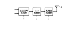
図1は、本発明にかかる送信装置(以下、送信機と呼ぶ)の実施の形態1の機能構成例を示す図である。図1に示すように、本実施の形態の送信装置は、本発明の特徴的な構成要素である送信信号生成部1と、D/A(Digital-to-Analog)変換部2と、高周波処理部3と、送信アンテナ4と、で構成される。
Embodiment 1 FIG.
FIG. 1 is a diagram illustrating a functional configuration example of a first embodiment of a transmission apparatus (hereinafter referred to as a transmitter) according to the present invention. As shown in FIG. 1, a transmission apparatus according to the present embodiment includes a transmission signal generation unit 1, a D / A (Digital-to-Analog)
送信信号生成部1は、送信機から受信装置(以下、受信機と呼ぶ)に対して伝達したい情報を含む情報ビット系列と、送信機の動作を制御する制御用信号と、に基づいてベースバンドのディジタル送信信号系列を生成し、D/A変換部2へ出力する。D/A変換部2では、入力されたベースバンドのディジタル送信信号系列をアナログ送信信号へ変換し、高周波処理部3へ出力する。高周波処理部3は、入力されたアナログ送信信号に対して、アップコンバート等の所定の高周波信号処理を施し、高周波アナログ送信信号を生成する。最終的に、高周波アナログ送信信号は、送信アンテナ4を介して送信される。
The transmission signal generation unit 1 is a baseband based on an information bit sequence including information to be transmitted from a transmitter to a receiving device (hereinafter referred to as a receiver) and a control signal for controlling the operation of the transmitter. Are transmitted to the D /
つづいて、本発明の特徴である、送信信号生成部1の構成例と動作について詳細に説明する。図2は、本実施の形態の送信機の送信信号生成部1の構成例を示す図である。図2に示すように、本実施の形態の送信信号生成部1は、制御部11と、分割部12と、サブブロック生成部13−1〜13−M(Mは1以上の整数)と、周波数割当部14と、逆DFT(Discrete Fourier Transform:離散フーリエ変換)処理部15と、CP(Cyclic Prefix)付加部16と、フレーム生成部17と、参照信号生成部18と、で構成される。また、送信信号生成部1へ入力される情報ビット系列は、分割部12へ入力される。
Next, a configuration example and operation of the transmission signal generation unit 1 that is a feature of the present invention will be described in detail. FIG. 2 is a diagram illustrating a configuration example of the transmission signal generation unit 1 of the transmitter according to the present embodiment. As shown in FIG. 2, the transmission signal generation unit 1 of the present embodiment includes a
はじめに、制御部11は、送信信号生成部1の各構成要素へ出力するパラメータを作成する。具体的には、図2の例では、制御部11は、分割部12が情報ビット系列をブロックに分割する際の分割数Mを決定して分割部12に通知する。また、制御部11は、サブブロック生成部13−1〜13−Mがそれぞれ用いる符号化方法や変調方式と、各ブロックに対して後述するサブブロックに分割する処理で必要となるサブブロック分割数Lと、を決定してそれぞれ対応するサブブロック生成部13−1〜13−Mに通知する。また、制御部11は、周波数割当部14および参照信号生成部18に対してはシステム帯域内で送信機が信号送信に使用する周波数(以下、使用周波数という)を含む情報(以下、使用周波数情報という)を通知する。各構成要素が実施する具体的な処理内容については後述する。
First, the
分割部12は、入力された情報ビット系列をM個のブロックに分割する処理を実行する。Mの具体的な数値は、制御部11から通知される。M個の各ブロックは、対応するサブブロック生成部13−1〜13−Mへ出力される。
The dividing
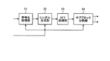
つぎに、サブブロック生成部13−1〜13−Mの構成例について説明する。図3は、サブブロック生成部13−1の構成例を示す図である。M個のサブブロック生成部13−1〜13−Mは、同一の構成をとるため、代表して、サブブロック生成部13−1の構成例を図3に例示している。図3に示すように、本実施の形態のサブブロック生成部13−1は、符号化処理部21と、シンボル生成部22と、DFT処理部23と、サブブロック分割部24と、で構成される。
Next, a configuration example of the sub-block generation units 13-1 to 13-M will be described. FIG. 3 is a diagram illustrating a configuration example of the sub-block generation unit 13-1. Since the M subblock generation units 13-1 to 13-M have the same configuration, a configuration example of the subblock generation unit 13-1 is illustrated in FIG. 3 as a representative. As illustrated in FIG. 3, the sub-block generation unit 13-1 according to the present embodiment includes an
分割部12から入力されたブロックは符号化処理部21へ入力され、制御部11から入力される符号化方法,変調方式,サブブロック分割数Lのパラメータは、それぞれ、符号化処理部21,シンボル生成部22,サブブロック分割部24へ入力される。
The block input from the dividing
符号化処理部21は、入力されたブロックに対して、制御部11から通知される符号化方法に従い誤り訂正符号化を行い、符号化ビット系列を生成する。具体的な符号化方法については、たとえば、良く知られている畳み込み符号や、ターボ符号、LDPC符号等、任意の方法が適用できる。また、符号化率等に関する制限もない。また、図3の例には示していないが、必要に応じて、符号化ビット系列の並びを入れ替えるインタリーブ処理を含んでも良い。生成された符号化ビット系列は、シンボル生成部22へ出力される。
The
シンボル生成部22は、入力された符号化ビット系列に対して、制御部11から通知された変調方式に従いシンボル系列を生成する。ここで用いられる変調方式としては、どのような変調方式を用いてもよいが、たとえば、1シンボルで2ビットを表現するQPSK(Quadrature Phase Shift Keying)や、1シンボルで4ビットを表現できる16QAM(Quadrature Amplitude Modulation)等の、公知の変調方式を適用することができる。生成されたシンボル系列は、DFT処理部23へ出力される。
The
DFT処理部23は、入力された、1ブロック分のシンボル系列に対して、DFT(Discrete Fourier Transform,離散フーリエ変換)を実行し、周波数領域のブロックを生成する。周波数領域のブロックは、サブブロック分割部24へ出力される。DFT処理部23の処理は、SC−FDMA方式で実施されるプリコーディング処理に相当する。したがって、DFT処理部23をプリコーディング手段と考えることができる。なお、プリコーディング処理は、これに限らず、どのようなプリコーディング処理を実施してもよい。
The
サブブロック分割部24は、制御部11から通知されるサブブロック分割数Lに基づき、入力された周波数領域のブロックを、L個のサブブロックに分割する。分割により生成されたL個のサブブロックは、図2の周波数割当部14へ出力される。
The
周波数割当部14は、サブブロック生成部13−1〜13−Mから入力された、M個のサブブロックを、制御部11から通知される使用周波数情報に基づいて所定の使用周波数に配置し(割り当て)、システム帯域内の使用周波数以外の周波数にはゼロを配置する処理を行う。
The
図4は、周波数割当部14の処理の一例の概念を示す図である。図4では、M=2かつ、各ブロックのサブブロック分割数をL=2とした場合を例示している。周波数割当部14の処理イメージを図示する。図4のブロック100−1,100−2は、それぞれ図2のサブブロック生成部13−1,13−2のDFT処理部23で生成された周波数領域のブロックを示している。また、サブブロック101−1,101−2は、サブブロック生成部13−1のサブブロック分割部24がブロック100−1を分割することにより生成したサブブロックを示し、サブブロック102−1,102−2は、サブブロック生成部13−2のサブブロック分割部24がブロック100−2を分割することにより生成したサブブロックを示している。
FIG. 4 is a diagram illustrating an example of a concept of processing of the
サブブロック103−1〜103−4は、それぞれサブブロック101−1,101−2,102−1,102−2が周波数割当部14により所定の周波数帯に割り当てられた後のサブブロックを示している。図4の例では、サブブロック生成部13−1〜13−2のDFT処理部23によって生成された2つの周波数領域のブロック(100−1および100−2)は、サブブロック生成部13−1〜13−Mにおけるサブブロック分割部24で、それぞれ、2つのサブブロックに分割される(101−1と101−2、102−1と102−2、など)。したがって、ここではM=2としているため、結果的に、周波数割当部14へ受け渡されるサブブロックは4つになる。
Sub-blocks 103-1 to 103-4 indicate sub-blocks after sub-blocks 101-1, 101-2, 102-1 and 102-2 are allocated to a predetermined frequency band by
周波数割当部14は、入力された4つのサブブロックを、制御部11から通知される使用周波数に配置し、システム帯域内のその他の周波数帯には何も信号を配置しないという処理を行う(103−1〜103−4)。最終的に、周波数割当部14は、システム帯域全体に相当する周波数領域信号を図2の逆DFT処理部15へ出力する。
The
逆DFT処理部15は、入力されたシステム帯域全体に相当する周波数領域信号に対して逆DFTの処理を行うことにより時間領域の送信信号系列を生成する。逆DFT処理部15は、処理結果である時間領域の送信信号系列をCP付加部16へ出力する。
The inverse
CP付加部16は、時間領域の送信信号系列の最後尾を複製し時間領域の送信信号系列の先頭にCP(Cyclic Prefix)として付加する。CPの長さは、たとえば、マルチパス伝搬に起因する遅延波の最大遅延時間より長くなるように設定する。CP付加部16は、CP付加後の時間領域の送信信号系列をフレーム生成部17へ出力する。
The
一方、参照信号生成部18は、これまでに説明してきた情報ビット系列に対する処理とは異なり、送信機と受信機との間で既知である参照信号を生成する。この参照信号は、受信機が、送信機と受信機との間の無線伝送路の応答を測定するために用いる。なお、無線伝送路の応答にはインパルス応答や周波数伝達関数などが含まれる。
On the other hand, the reference
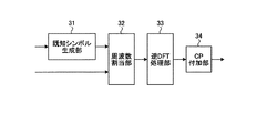
図5は、参照信号生成部18の構成例を示す図である。図5に示すように本実施の形態の参照信号生成部18は、既知シンボル生成部31と、周波数割当部32と、逆DFT処理部33と、CP付加部34と、を備えている。なお、図2の制御部11から入力される、使用周波数情報は、周波数割当部へ入力される。以下、図5を用いて、参照信号生成部18の動作例を詳細に説明する。
FIG. 5 is a diagram illustrating a configuration example of the reference
はじめに、既知シンボル生成部31は、あらかじめ送信機と受信機の双方で保持している既知シンボルを、周波数割当部32へ出力する。周波数割当部32は、制御部11から通知される、使用周波数情報に基づき既知シンボル生成部31から入力される既知シンボルをシステム帯域内の使用周波数に配置し、システム帯域内の使用周波数以外の周波数には何も信号を配置しないという処理を行い、処理後のシステム帯域幅全体に相当する周波数領域信号を逆DFT処理部33へ出力する。
First, the known
逆DFT処理部33は、図2の逆DFT処理部15と同様に、入力された周波数領域信号に対して逆DFTの処理を行うことにより時間領域の参照信号を生成する。そして、逆DFT処理部15は、時間領域の参照信号をCP付加部34へ出力する。その後、CP付加部34は、時間領域の参照信号の最後尾をCPとして先頭に複製し、図2のフレーム生成部17へ出力する。
Similar to the inverse
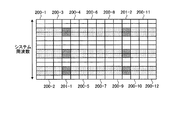
図2のフレーム生成部17は、CP付加部16から入力されたCP付加後の時間領域の送信信号系列と、参照信号生成部18から入力されたCP付加後の時間領域の参照信号と、を所定のフレーム構成になるように配置する。図6は、本実施の形態のフレーム構成例を示す図である。図6の送信信号系列200−1〜200−12は、12個のCP付加後の時間領域の送信信号系列を示し、参照信号201−1,201−2は2個のCP付加後の時間領域の参照信号を示している。また、図6の濃い塗りつぶしの部分は、既知シンボルが割り当てられている周波数を示し、薄い塗りつぶし部分はサブブロックが割り当てられている部分を示し、塗りつぶされていない部分は信号が割り当てられていない周波数を示している。
The
図6では、横方向に時間を、縦方向に各時間領域信号の周波数成分を示している。フレーム生成部17へ入力されるCP付加後の時間領域の送信信号系列と、CP付加後の時間領域の参照信号と、は、時間方向に多重化されて1つのフレームを構成している。また、前述したように、送信信号系列と参照信号は、同じ周波数(使用周波数)に各々の信号成分が割り当てられている。フレーム生成部17の処理結果は、図1のD/A変換部2へ出力され、前述したようにD/A変換部2および高周波処理部で所定の処理が施された後、送信アンテナ4から送出される。
In FIG. 6, time is shown in the horizontal direction, and frequency components of each time domain signal are shown in the vertical direction. The time domain transmission signal sequence after CP addition and the time domain reference signal after CP input to the
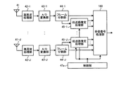
つづいて、本実施の形態の受信機の動作について説明する。図7は、本実施の形態の受信機の構成例を示す図である。図7に示すように本実施の形態の受信機は、受信アンテナ41と、高周波処理部42と、A/D変換部43と、フレーム分割部44と、伝送路推定処理部45と、受信信号処理部46と、制御部47と、で構成される。図7を用いて、本実施の形態の受信機の動作概要を説明する。
Next, the operation of the receiver of this embodiment will be described. FIG. 7 is a diagram illustrating a configuration example of a receiver according to the present embodiment. As shown in FIG. 7, the receiver according to the present embodiment includes a
受信アンテナ41は、高周波アナログ信号を受信し、高周波処理部42は、高周波アナログ信号に対してベースバンドへのダウンコンバート等の所定の高周波信号処理を施してベースバンドアナログ受信信号とし、A/D変換部43が、ベースバンドアナログ受信信号をベースバンドディジタル受信信号に変換する。以降では、ベースバンドディジタル受信信号を受信フレームと呼ぶことにする。A/D変換部43は、受信フレームをフレーム分割部44へ出力する。
The
フレーム分割部44は、受信フレームを、送信信号系列が配置されている部分(以下、受信信号系列という)と、参照信号が配置されている部分(以下、受信参照信号という)と、に分離し、それぞれ受信信号処理部46,伝送路推定処理部45へ出力する。伝送路推定処理部45は、受信参照信号を用いて信号が伝搬してきた無線伝送路の応答を推定し、推定結果を受信信号処理部46へ出力する。
The
受信信号処理部46は、受信信号系列と無線伝送路の応答の推定結果とに基づいて後述する復調処理および復号処理を実行し、最終的に、情報ビット系列の推定値を出力する。受信信号処理部46および伝送路推定処理部45の詳細な処理内容は後述する。一方、制御部47は、伝送路推定処理部45および受信信号処理部46が所定の信号処理を実行するために必要なパラメータを決定して通知する。図7の例では、伝送路推定処理部45に対しては、パラメータとして、ブロック分割数Mと、各ブロックのサブブロック分割数Lと、システム帯域で送信機が信号送信に使用する周波数(使用周波数)に関する情報と、が通知される。受信信号処理部46に対しては、前記パラメータに加えて、各ブロックが用いる符号化方法や変調方式に関するパラメータも通知される。以降では、伝送路推定処理部45および受信信号処理部46の動作例について、詳細に説明する。
The reception
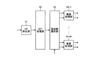
図8は、伝送路推定処理部45の構成例を示す図である。図8に示すように、本実施の形態の伝送路推定処理部45は、CP除去部51と、DFT処理部52と、周波数選択部53と、乗算処理部54−1〜54−Mと、で構成される。伝送路推定処理部45に入力される受信参照信号は、CP除去部51に入力され、制御部47から入力されるパラメータは、周波数選択部53に入力される。
FIG. 8 is a diagram illustrating a configuration example of the transmission path
また、伝送路推定処理部45は、送信機と受信機の間の無線伝送路の周波数伝達関数を出力する。以下、伝送路推定処理部45の処理について詳細に説明する。
The transmission path
CP除去部51は、受信参照信号からCPを除去し、その結果をDFT処理部52へ出力する。DFT処理部52は、受信参照信号に対してDFTを実行することにより周波数領域の受信参照信号を生成し、生成した受信参照信号を周波数選択部53へ出力する。
周波数選択部53は、制御部47より通知される、使用周波数情報とブロック分割数Mとサブブロック分割数Lとに基づき、入力された周波数領域の受信参照信号から既知シンボルが割り当てられている周波数の信号のみ抽出し、乗算処理部54−1〜54−Mへ出力する。ここで、前述の送信機の動作で説明したように、送信機では参照信号とする既知シンボルを、サブブロックが割当てられている周波数と同じ周波数に配置していることとする。以下、周波数選択部53から乗算処理部54−1〜54−Mへ出力される信号を、「サブブロック毎の受信参照信号」と呼ぶこととする。
The
乗算処理部54−1〜54−Mは、参照信号として送信される既知シンボルをあらかじめ保持していることとする。乗算処理部54−1〜54−Mは、既知シンボルの複素共役をとり、それぞれに入力された「サブブロック毎の受信参照信号」に乗算し、乗算結果を、既知シンボルを2乗した値で除算する処理を行う。 The multiplication processing units 54-1 to 54-M hold in advance a known symbol transmitted as a reference signal. Multiplication processing units 54-1 to 54-M take complex conjugates of known symbols, multiply the received reception signals for each sub-block, and multiply the multiplication results by squares of known symbols. Process to divide.
以下、数式を用いてより詳細に説明する。i番目の周波数の受信信号,送信された既知シンボルをそれぞれx,dで表現することとする。また、i番目の周波数における無線伝送路の周波数伝達関数,雑音成分をそれぞれh,nで表すこととする。このとき、以下の式(1)が成り立つ。
x=hd+n …(1)
Hereinafter, it demonstrates in detail using numerical formula. The received signal of i-th frequency and the transmitted known symbol are expressed by x and d, respectively. The frequency transfer function and noise component of the wireless transmission path at the i-th frequency are represented by h and n, respectively. At this time, the following expression (1) is established.
x = hd + n (1)
したがって、前述の乗算処理部54−1〜54−Mの処理を実行すると、i番目の周波数における処理結果は以下の式(2)で表現できる。
d*x/|d|2=h+d*n/|d|2 …(2)
ここで、d*は、dの複素共役を表す。
Accordingly, when the processing of the above-described multiplication processing units 54-1 to 54-M is executed, the processing result at the i-th frequency can be expressed by the following equation (2).
d * x / | d | 2 = h + d * n / | d | 2 (2)
Here, d * represents a complex conjugate of d.
上記式(1)および(2)からわかるように、以上の処理によって、対象となっている周波数における無線伝送路の周波数伝達関数hの推定値を得ることができる。乗算処理部54−1〜54−Mが算出した無線伝送路の周波数伝達関数は、それぞれ受信信号処理部46へ出力される。
As can be seen from the above equations (1) and (2), an estimated value of the frequency transfer function h of the radio transmission path at the target frequency can be obtained by the above processing. The frequency transfer functions of the wireless transmission paths calculated by the multiplication processors 54-1 to 54-M are output to the received
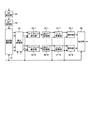
次に、受信信号処理部46の動作について詳細に説明する。図9は、受信信号処理部46の構成例を示す図である。図9に示すように本実施の形態の受信信号処理部46は、CP除去部61と、DFT処理部62と、周波数選択部63と、等化処理部64と、サブブロック結合部65−1〜65−Mと、逆DFT処理部66−1〜66−Mと、ビット変換部67−1〜67−Mと、復号部68−1〜68−Mと、結合部69で構成される。
Next, the operation of the received
受信信号処理部46に入力される受信信号系列はCP除去部61に入力され、伝送路推定処理部45の処理結果である無線伝送路の周波数伝達関数は等化処理部64に入力される。また、制御部47から入力されるパラメータのうち、使用周波数情報は周波数選択部63へ、ブロック分割数Mは周波数選択部63、サブブロック結合部65−1〜65−Mおよび結合部69へ、各ブロックのサブブロック分割数Lは周波数選択部63およびサブブロック結合部65−1〜65−Mへ、各ブロックに対応する変調方式はビット変換部67−1〜67−Mへ、各ブロックに対応する符号化方法は復号部68−1〜68−Mへ、それぞれ入力される。
The received signal sequence input to the received
はじめに、CP除去部61は、受信信号系列の先頭からCPを除去し、CP除去後の受信信号系列をDFT処理部62へ出力する。DFT処理部62は、CP除去後の受信信号系列から入力された信号に対してDFTを実行することにより受信信号系列のシステム帯域全体に渡る周波数成分を計算し、周波数領域の受信信号を得る。
First, the
周波数選択(抽出)部63は、制御部47から通知される、使用周波数情報とブロック分割数Mとサブブロック分割数Lに基づき、周波数領域の受信信号から送信機がサブブロックに割り当てた周波数の信号のみを抽出し、抽出した周波数領域の受信信号を等化処理部64に出力する。
The frequency selection (extraction)
等化処理部64は、入力された周波数領域の受信信号に対して信号が無線伝送路で受けたひずみを補償する処理を行う。具体的には、つぎのような処理を行う。i番目の周波数における、受信信号,送信信号をそれぞれx,sで表し、i番目の周波数における無線伝送路の周波数伝達関数をhで表すこととする。更に、i番目の周波数における雑音成分をnで表すこととする。このとき、以下の式(3)が成り立つ。
x=hs+n …(3)
The
x = hs + n (3)
ここで、伝送路推定処理部45から入力されるhの推定値が正しいと仮定すると、以下の式(4)に示すように、xに対してhの複素共役を乗算し、更にhの2乗値で除算することで、周波数領域の送信信号推定値が得られる。
h*x/|h|2=s+h*n/|h|2 …(4)
Here, assuming that the estimated value of h input from the transmission path
h * x / | h | 2 = s + h * n / | h | 2 (4)
上記式(4)の処理で得られた周波数領域の送信信号推定値は、サブブロック生成部13−1〜13−Mが生成する周波数領域のサブブロックの推定値となる。等化処理部64は、各周波数領域のサブブロックの推定値を、対応するサブブロック結合部65−1〜65−Mに対して出力する。
The frequency domain transmission signal estimation value obtained by the processing of the above equation (4) is an estimation value of the frequency domain sub-block generated by the sub-block generation units 13-1 to 13-M. The
サブブロック結合部65−1〜65−Mは、制御部47から通知されるブロック分割数Mおよび各ブロックのサブブロック分割数Lの情報に基づいて入力された周波数領域のサブブロックの推定値を結合し、サブブロック生成部13−1〜13−MのDFT処理部23の出力である周波数領域のブロックの推定値を得る。サブブロック結合部65−1〜65−Mは、周波数領域のブロックの推定値を、それぞれ対応する逆DFT処理部66−1〜66−Mへ出力する。
The sub-block combining units 65-1 to 65 -M receive the estimated values of the frequency domain sub-blocks input based on the information on the block division number M and the sub-block division number L of each block notified from the control unit 47. Combined to obtain an estimated value of the block in the frequency domain that is the output of the
逆DFT処理部66−1〜66−Mは、それぞれ入力された周波数領域のブロックの推定値に対して逆DFTを実行することにより時間領域の送信シンボルの推定値を得て、時間領域の送信シンボルの推定値を対応するビット変換部67−1〜67−Mへそれぞれ出力する。 The inverse DFT processing units 66-1 to 66 -M obtain the estimated value of the transmission symbol in the time domain by performing inverse DFT on the estimated value of the block in the frequency domain, respectively, and transmit the estimated value in the time domain. The estimated symbol values are output to the corresponding bit conversion units 67-1 to 67-M.
ビット変換部67−1〜67−Mは、制御部47から通知される各ブロックの変調方式の情報に基づき、入力された時間領域の送信シンボルの推定値から符号化ビット系列の推定値を計算し、計算結果をそれぞれ対応する復号部68−1〜68−Mへ出力する。ここで、送信シンボルの推定値から符号化ビット系列へ変換する手法は、従来知られている任意の方法を適用可能である。たとえば、送信シンボルの推定値と、変調方式で定まる信号点配置とを比較し、最も近い信号点が送信されているものと判断して対応するビットに変換する、硬判定を用いることができる。ビット変換部67−1〜67−Mは、入力された時間領域の送信シンボルの推定値全てについて符号化ビット系列に変換し、符号化ビット系列を対応する復号部68−1〜68−Mへ出力する。 Based on the modulation scheme information of each block notified from the control unit 47, the bit conversion units 67-1 to 67-M calculate the estimated value of the encoded bit sequence from the input estimated value of the transmission symbol in the time domain. Then, the calculation results are output to the corresponding decoding units 68-1 to 68-M. Here, any conventionally known method can be applied to the method of converting the estimated value of the transmission symbol into the encoded bit sequence. For example, it is possible to use a hard decision in which an estimated value of a transmission symbol is compared with a signal point arrangement determined by a modulation scheme, and the closest signal point is determined to be transmitted and converted into a corresponding bit. The bit converters 67-1 to 67-M convert all the estimated values of the input transmission symbols in the time domain into encoded bit sequences, and the encoded bit sequences to the corresponding decoding units 68-1 to 68-M. Output.
復号部68−1〜68−Mは、制御部47から通知される、各ブロックにおける符号化方法に関する情報に基づき、入力された符号化ビット系列の推定値に対して、誤り訂正復号の処理を行い、ブロックごとの情報ビット系列の推定値を得る。ここで、送信機がインタリーブ処理を実行している場合、誤り訂正復号前に所定の逆インタリーブ処理を施す。復号部68−1〜68−Mは、情報ビット系列の推定値を、結合部69へ出力し、結合部69は、制御部47から通知されるブロック数Mに関する情報に基づき、M個のブロックの情報ビット系列の推定値を結合して、ブロックに分割される前の情報ビット系列を復元する。
The decoding units 68-1 to 68-M perform error correction decoding processing on the input estimated value of the encoded bit sequence based on the information regarding the encoding method in each block notified from the control unit 47. To obtain an estimated value of the information bit sequence for each block. Here, when the transmitter is executing the interleaving process, a predetermined deinterleaving process is performed before error correction decoding. Decoding sections 68-1 to 68 -M output the estimated value of the information bit sequence to combining
このように、本実施の形態では、送信機の分割部12が、情報ビット系列を複数系統のブロックに分割し、ブロック毎に符号化処理、シンボル生成処理、およびDFT処理を用いて、複数の周波数領域のブロックに変換する。また、サブブロック生成部13−1〜13−Mが、周波数領域のブロックを、それぞれさらに複数のサブブロックに分割し、周波数割当部14がサブブロックをシステム帯域全体の任意の周波数に割り当てるようにした。このため、周波数領域のブロック間で、異なる符号化や変調方式を適用し、周波数領域のブロックをシステム帯域の所望の周波数に配置することにより高い伝送効率を実現することができる。また、サブブロックの生成方法を、周波数領域のブロックを複数のサブブロックに分割する構成としているため、PAPRを低く抑えることができる。
As described above, in this embodiment, the
一方、受信機では、周波数選択部63が、DFT処理後の受信信号からシステム帯域全体のなかから所定の周波数成分を抽出し、周波数領域のサブブロックを抽出する構成とした。また、等化処理部64が、周波数領域のサブブロックに対して等化処理を行い無線伝送路のひずみを補正した後、サブブロック結合部65−1〜65−Mが周波数領域のサブブロックを結合し、元の周波数領域のブロックを再生するようにした。このため、上述のように、送信機が情報ビット系列から生成された複数の周波数領域のブロックを、更に複数のサブブロックに分割してサブブロックをシステム帯域全体の所望の周波数に割り当てる処理を行っている場合でも、復調および復号を行うことができる。
On the other hand, in the receiver, the
なお、本実施の形態では、参照信号生成部18が、既知シンボルを、情報ビット系列から一連の処理を経て生成される周波数領域のサブブロックが割り当てられている周波数に配置する構成としたが、参照信号の生成方法はこれに限定されず、たとえば、時間領域の参照信号の波形を蓄積しておき、それを読み出す方式にすることもできる。また、参照信号と情報ビット系列とを時間多重して送信するようにしてもよい。
In the present embodiment, the reference
また、参照信号を配置する周波数についても、任意の位置にすることができる。たとえば、周波数領域のサブブロックが割り当てられている周波数とは無関係のあらかじめ決められた周波数に既知シンボルを割り当て、受信機の伝送路推定処理部45が、既知シンボルが割り当てられていない周波数の周波数伝達関数を補間して、サブブロックが割り当てられている周波数の周波数伝達関数を求めるようにしてもよい。その他、参照信号の構成としては、考えうる全ての構成が適用可能である。
Also, the frequency at which the reference signal is arranged can be set to an arbitrary position. For example, a known symbol is assigned to a predetermined frequency irrelevant to the frequency to which the frequency domain sub-block is assigned, and the transmission path
また、本実施の形態では、図4に例示したように、周波数領域のサブブロックを、番号順にシステム周波数に割り当てる構成としているが、周波数領域のサブブロックの割当方法はこれに限定されず、たとえば、異なる周波数領域のブロックから生成された、周波数領域のサブブロックを、周波数軸上で互い違いになるように配置することもできる。このような構成とすることで、たとえば、各ブロックに適用されている変調方式が異なり、要求される通信路の品質(SNR:Signal to Noise Ratioや、SINR:Signal to Interference and Noise Ratio等)が一定ではないような場合に、より柔軟なサブブロック配置を実現でき、結果的に高品質で大容量な無線伝送を提供できる。 Further, in the present embodiment, as illustrated in FIG. 4, the frequency domain sub-blocks are allocated to the system frequencies in numerical order, but the frequency domain sub-block allocation method is not limited to this, for example, The frequency domain sub-blocks generated from the different frequency domain blocks may be arranged alternately on the frequency axis. By adopting such a configuration, for example, the modulation scheme applied to each block differs, and the required channel quality (SNR: Signal to Noise Ratio, SINR: Signal to Interference and Noise Ratio, etc.) When it is not constant, a more flexible sub-block arrangement can be realized, and as a result, high-quality and large-capacity wireless transmission can be provided.
また、サブブロックを周波数軸に割当てる際に、同一のブロックから生成された複数のサブブロックが周波数軸上で離れた位置に配置されるように構成することもできる。無線伝送路の相関は、周波数が離れるほど小さくなるため、同一のブロックから生成された複数のサブブロックを周波数軸上で離れた位置に割当てることで、周波数ダイバーシチの効果が得られ、結果的に高品質伝送を実現することができる。 Further, when assigning sub-blocks to the frequency axis, a plurality of sub-blocks generated from the same block may be arranged at positions separated on the frequency axis. Since the correlation of the wireless transmission path decreases as the frequency increases, the effect of frequency diversity can be obtained by assigning multiple sub-blocks generated from the same block to positions separated on the frequency axis. High quality transmission can be realized.
また、周波数領域のサブブロックは、必ずしも周波数軸上で離れて配置する必要は無く、周波数領域のサブブロック同士が隣接した周波数に割り当てられても良い。このような構成をとると、たとえば、通信品質の良い(SNRやSINRが高い)周波数に集中的にサブブロックを割当てることができ、高品質な無線伝送を提供できる。 Further, the frequency domain sub-blocks are not necessarily arranged separately on the frequency axis, and the frequency domain sub-blocks may be assigned to adjacent frequencies. With such a configuration, for example, it is possible to concentrate sub-blocks on frequencies with good communication quality (high SNR and SINR), and provide high-quality wireless transmission.
また、各ブロックに対して適用される符号化方法、変調方式、および、サブブロック分割数は、同一である必要は無く、ブロック毎に任意の設定にすることができる。また、図2の分割部12が情報ビット系列を複数のブロックに分割する際には、ブロックに含まれる情報ビット数はブロック間で均一である必要はない。更に、ブロック内の各サブブロックのサイズも、それぞれ異なる値にすることができる。このような構成とすることで、様々なサイズ、所要SNRまたは所要SINRなどを有するサブブロックを形成でき、サブブロックを周波数に割当てる際の柔軟性が向上する。結果的に、高品質、大容量無線伝送を提供可能となる。
Also, the encoding method, the modulation scheme, and the number of sub-block divisions applied to each block need not be the same, and can be set arbitrarily for each block. When the dividing
また、本実施の形態では、システム帯域は連続的であるような構成を仮定したが、システム帯域は必ずしも連続である必要は無く、周波数軸上で離れて存在しているサブシステム帯域を複数備えるシステムにも本発明は問題なく適用できる。 In this embodiment, it is assumed that the system band is continuous. However, the system band does not necessarily have to be continuous, and includes a plurality of subsystem bands that are separated on the frequency axis. The present invention can be applied to a system without any problem.
また、本実施の形態では、送信機,受信機の動作は、それぞれ制御部11,制御部47から通知されるパラメータに基づいて決定される構成とした。このとき、制御部11,制御部47から通知されるパラメータは、通信を行っている間に固定である必要は無く、システムがサポートする動作様態の範囲内であれば自由に変更することができる。たとえば、システム帯域内の比較的広い連続した周波数に渡ってSNRまたはSINRが高い状態である場合、制御部11,制御部47は、M=1、L=1と設定し、当該周波数に連続的にサブブロックを割当てるように動作する。また、SNRまたはSINRが高い周波数がシステム帯域内に離散的に存在しており、かつ、当該周波数帯のSNRまたはSINRの値が同程度であるような状態では、M=1とし、Lを2以上に設定する。
In the present embodiment, the operations of the transmitter and the receiver are determined based on parameters notified from the
また、厳しい周波数選択性フェージングが存在し、周波数伝達関数の周波数軸上の変動が大きいような場合には、Mを大きな値に設定し、各ブロックで適用する変調方式や符号化方法を無線伝送路の周波数特性に適合するように細かく設定する。このような制御を行うことで、大容量伝送と送信機におけるPAPR抑圧の双方を実現することができる。もちろん、MおよびLの範囲に制限はなく、制御部11,制御部47は任意の組み合わせでパラメータ変更可能であることは言うまでもない。
Also, when severe frequency selective fading exists and the frequency transfer function has a large fluctuation on the frequency axis, M is set to a large value, and the modulation method and coding method applied to each block are transmitted wirelessly. Finely set to match the frequency characteristics of the road. By performing such control, both large-capacity transmission and PAPR suppression at the transmitter can be realized. Of course, there is no limit to the range of M and L, and it goes without saying that the
また、このように送信機および受信機が用いるパラメータを変更するような構成とする場合、送信機の制御部11と受信機の制御部47は、同じパラメータを設定する必要があるが、同じパラメータを設定するための方法は任意の方式を適用することができる。たとえば、送信機が受信機に対して信号を送信するのに先立って、送信機から送信された既知信号に基づいて受信機が無線伝送路の状態を測定しておき、受信機の方から所望のパラメータを送信機に対して通知する方法や、あらかじめパラメータの組み合わせと使う順序を決めておき、その順序に従って逐次変更していく方法をとることができる。また、別な実現方法として、フレーム内に、送信機から受信機へパラメータを通知するための専用信号を多重化し、当該フレームで用いられているパラメータを、専用信号を用いて受信機に通知し、受信機の制御部47が、パラメータ通知用の専用信号を読み取ることでパラメータを設定するという構成も考えられる。
Further, when the configuration is such that the parameters used by the transmitter and the receiver are changed in this way, the
また、本実施の形態では、送信機の逆DFT処理部15が、システム帯域全体に対応する時間領域の信号を生成する構成としたが、たとえば、システム帯域より小さい周波数幅に対応する複数の逆DFT処理部を備え、それぞれの時間領域の信号をシステム帯域内の所定の周波数に割り当てるようにしてもよい。この場合、逆DFT処理にかかる処理量を削減することが可能である。また、このような構成は、前述した、周波数軸上で離れて存在しているサブシステム帯域を複数備えるような場合に好適であり、たとえば、複数の逆DFT処理部を、各サブシステム帯域に対応させることができる。
In this embodiment, the inverse
また、本実施の形態では、送信機および受信機が、それぞれ1本のアンテナを備える構成としたが、送信機が複数の送信アンテナを用いて本発明によって生成される無線送信信号を同時に送出する構成としてもよい。また、受信機が、複数の受信アンテナを用いて信号を受信する構成としても良い。送信機が複数の送信アンテナを用いて送信する場合、受信機では、送信アンテナごとに、送信された各々の信号を分離する必要がある。これは、たとえば、「Xu Zhu and Ross D. Murch,“Novel Frequency-Domain Equalization Architectures for a Single-Carrier Wireless MIMO System”,IEEE VTC2002-Fall,pp.874-878」に開示されているような、公知の信号分離アルゴリズムを等化処理部に適用することで達成できる。また、送信機および受信機において複数のアンテナを用いた場合、たとえばSTBC(Space−Time Block Code)やSFBC(Space−Frequency Block Code)、ビームフォーミングといったような、複数アンテナを用いて信号の送受信を行うシステムに適用できる各種アルゴリズムと組み合わせる構成にすることも可能である。 In this embodiment, each of the transmitter and the receiver includes one antenna. However, the transmitter simultaneously transmits a radio transmission signal generated by the present invention using a plurality of transmission antennas. It is good also as a structure. The receiver may receive signals using a plurality of receiving antennas. When the transmitter transmits using a plurality of transmission antennas, the receiver needs to separate the transmitted signals for each transmission antenna. This is, for example, as disclosed in “Xu Zhu and Ross D. Murch,“ Novel Frequency-Domain Equalization Architectures for a Single-Carrier Wireless MIMO System ”, IEEE VTC2002-Fall, pp. 874-878” This can be achieved by applying a known signal separation algorithm to the equalization processing unit. In addition, when a plurality of antennas are used in the transmitter and the receiver, for example, signals are transmitted and received using a plurality of antennas such as STBC (Space-Time Block Code), SFBC (Space-Frequency Block Code), and beamforming. It is also possible to adopt a configuration combined with various algorithms applicable to the system to be performed.
また、本実施の形態の構成に限定されず、送信機がブロック化した送信系列をサブブロックに分割して上記と同様の信号の送信ができる構成であればどのような構成としてもよく、また、受信機についてもサブブロック化されて送信された信号を復元できるような構成であればどのような構成としてもよい。 Further, the present invention is not limited to the configuration of the present embodiment, and any configuration may be used as long as it can transmit a signal similar to the above by dividing the transmission sequence blocked by the transmitter into sub-blocks. As for the receiver, any configuration may be used as long as it can restore the signal transmitted in the sub-block form.
実施の形態2.
図10は、本発明にかかる実施の形態2の送信機のサブブロック生成に関連する構成要素の構成例を示す図である。本実施の形態の送信機の構成は、制御部11を制御部11aに替え、分割部12およびサブブロック生成部13−1〜13−Mの替わりに、第一の分割部12a,第二の分割部12b,第三の分割部12cを備えるが、それ以外は実施の形態1の送信機と同様である。ただし、符号化処理部21、シンボル生成部22およびDFT処理部23については、機能は実施の形態1と同様であるが、各構成要素の個数は後述のように実施の形態1とは異なる。実施の形態1と同様の機能を有する構成要素については同一の符号を付して説明を省略する。以下、実施の形態1と異なる部分について説明する。
FIG. 10 is a diagram illustrating a configuration example of components related to sub-block generation of the transmitter according to the second embodiment of the present invention. The configuration of the transmitter according to the present embodiment is such that the
本実施の形態の送信機が、実施の形態1の送信機と異なる主な点は、ブロック分割を信号生成処理の任意の位置(処理段階)で行うことができるようにしている点である。図10の例では、第一の分割部12aが、制御部11aからの通知に基づいて送信する情報ビット系列をA個の情報ビットブロックに分割して、情報ビットブロックを対応する符号化処理部21に出力する。なお、図10では、代表して1番目のブロックに関する構成要素のみ図示しているが、A個のブロックについて、それぞれ対応する符号化処理部21および第二の分割部12bを備えることとする。すなわち、符号化処理部21および第二の分割部12bをA個備えることとする。符号化処理部21は、情報ビットブロック内の情報ビットに対して誤り訂正符号化を実行することにより符号化ビット系列を生成し、符号化ビット系列を第二の分割部12bへ出力する。
The main difference between the transmitter of this embodiment and the transmitter of Embodiment 1 is that block division can be performed at an arbitrary position (processing stage) of the signal generation processing. In the example of FIG. 10, the
第二の分割部12bは、制御部11aからの通知に基づいて入力された符号化ビット系列を符号化ビットブロックに分割して、符号化ビットブロックを対応するシンボル生成部22に出力する。このとき、A個の第二の分割部12bから出力される符号化ビットブロックの合計の個数をB個とする。図10では、代表して1番目のブロックに関する構成要素のみ図示しているが、B個のブロックについて、それぞれ対応する符号化処理部22および第三の分割部12cを備えることとする。すなわち、符号化処理部22および第三の分割部12cをB個備えることとする。シンボル生成部22は、符号化ビットブロック内の符号化ビットをシンボル系列に変換し、シンボル系列を第三の分割部12cへ出力する。
The
第三の分割部12cは、制御部11aからの通知に基づいて入力されたシンボル系列をシンボルブロックに分割し、シンボルブロックをDFT処理部23へ出力する。このとき、B個の第二の分割部12bから出力される符号化ビットブロックの合計の個数をC個とする。図10では、代表して1番目のブロックに関する構成要素のみ図示しているが、C個のブロックについて、それぞれ対応するDFT処理部23およびサブブロック分割部24をそれぞれC個備えることとする。DFT処理部23は、シンボルブロックに対してDFTを実行することにより周波数領域のブロックを生成し、周波数領域のブロックをサブブロック分割部24へ出力する。サブブロック分割部24は、周波数領域のブロックを複数の周波数領域のサブブロックに分割し、周波数割当部14へ出力する。以降の処理は、実施の形態1と同様である。
The
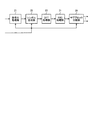
つづいて、本実施の形態の受信機の構成および動作について説明する。実施の形態1と異なる点について説明する。図11は、本実施の形態の受信機の受信信号処理部の結合処理に関連する構成要素の構成例を示す図である。本実施の形態の受信機の受信信号処理部は、実施の形態1の受信信号処理部46の結合部69の替わりに、第一の結合部69a,第二の結合部69b,第三の結合部69cを備えているが、それ以外は実施の形態の受信信号処理部46と同様である。図11では、CP除去部61,DFT処理部62,周波数選択部63,等化処理部64を省略しているが、本実施の形態でも、実施の形態1と同様にこれらの構成要素を備えていることとする。
Next, the configuration and operation of the receiver of this embodiment will be described. Differences from the first embodiment will be described. FIG. 11 is a diagram illustrating a configuration example of components related to the combining process of the reception signal processing unit of the receiver according to the present embodiment. The reception signal processing unit of the receiver according to the present embodiment replaces the
また、本実施の形態では、サブブロック結合部65−1および逆DFT処理部66−1の1式のみを示しているが、サブブロック結合部65−1〜65−Cおよび逆DFT処理部66−1〜66−Cのように、それぞれC個備えることとする。また、本実施の形態では、ビット変換部67−1〜67−Bを第一の結合部69aと第二の結合部69bの間に、復号部68−1〜68−Aを第二の結合部69bと第三の結合部69cの間に配置している。図11では、簡単のため、ビット変換部67−1,復号部68−1のみを示している。
In the present embodiment, only one set of the sub-block combining unit 65-1 and the inverse DFT processing unit 66-1 is shown, but the sub-block combining unit 65-1 to 65-C and the inverse
つづいて、本実施の形態の受信機の受信信号処理部の動作について、実施の形態1と異なる部分について説明する。サブブロック結合部65−1〜5−Cは、実施の形態1と同様に、制御部47から通知されるサブブロック分割数の情報に基づき等化処理部64から入力された周波数領域のサブブロックの推定値を結合し、周波数領域のブロックの推定値を生成する。そして、サブブロック結合部65−1〜5−Cは、周波数領域のブロックの推定値をそれぞれ対応する逆DFT処理部66−1〜66−Cに出力する。
Subsequently, the operation of the reception signal processing unit of the receiver according to the present embodiment will be described with respect to differences from the first embodiment. Similarly to the first embodiment, the sub-block combining units 65-1 to 65 -C are frequency domain sub-blocks input from the
逆DFT処理部66−1〜66−Cでは、周波数領域のブロックの推定値に対して逆DFTを実行することによりシンボルブロックの推定値を得て、シンボルブロックの推定値を第一の結合部69aに出力する。 The inverse DFT processing units 66-1 to 66 -C obtain an estimated value of the symbol block by performing an inverse DFT on the estimated value of the block in the frequency domain, and the estimated value of the symbol block is converted into the first combining unit. To 69a.
第一の結合部69aは、C個のシンボルブロックの推定値を、制御部47から通知されるブロック分割情報(ブロック分割数A,B,Cを含む情報)に基づいて結合し、シンボル系列の推定値を生成し、シンボル系列の推定値をそれぞれビット変換部67−1〜67−Bに出力する。
The
ビット変換部67−1〜67−Bは、それぞれ制御部47から通知される変調方式に関する情報に基づき入力されたシンボル系列の推定値に含まれる各シンボルの推定値を、ビット単位の推定値に変換することにより、符号化ビットブロックの推定値を生成する。そして、符号化ビットブロックの推定値を第二の結合部69bに出力される。
Each of the bit conversion units 67-1 to 67-B converts the estimated value of each symbol included in the estimated value of the symbol sequence input based on the information on the modulation scheme notified from the control unit 47 into the estimated value in bit units. By performing the conversion, an estimated value of the encoded bit block is generated. Then, the estimated value of the encoded bit block is output to the
第二の結合部69bは、B個の符号化ビットブロックの推定値を、制御部47から通知されるブロック分割情報に基づいて結合し、符号化ビット系列の推定値を生成する。そして、符号化ビット系列の推定値を、復号部68−1〜68−Aへそれぞれ出力される。
The
復号部68−1〜68−Aは、制御部47から通知される符号化方法に関する情報に基づき入力された符号化ビット系列に対して誤り訂正復号の処理を行い、情報ビットブロックの推定値を得る。ここで、送信機においてインタリーブ処理が行われている場合、逆の処理に相当する逆インタリーブも行う。復号部68−1〜68−Aは、情報ビットブロックの推定値を第三の結合部69cへ出力される。
The decoding units 68-1 to 68-A perform error correction decoding processing on the encoded bit sequence input based on the information on the encoding method notified from the control unit 47, and obtain the estimated value of the information bit block. obtain. Here, when interleave processing is performed in the transmitter, reverse interleave corresponding to the reverse processing is also performed. The decoding units 68-1 to 68-A output the estimated value of the information bit block to the third combining
第三の結合部69cは、A個の情報ビットブロックの推定値を、制御部47から通知されるブロック分割数Aに基づいて結合し、分割前の情報ビット系列の推定値を得る。以上のべた以外の本実施の形態の動作は、実施の形態1と同様である。
The
このような構成とすることで、たとえば、A=M,B=1,C=1とする場合には、実施の形態1と同様に符号化前の送信する情報ビット系列の段階でブロックに分割することができ、A=1,B=M,C=1とすれば、符号化処理後の符号化ビット列の段階でブロックに分割することができ、また、A=1,B=1,C=Mとすれば、シンボル系列の段階でブロックに分割することができる。 By adopting such a configuration, for example, when A = M, B = 1, and C = 1, as in Embodiment 1, it is divided into blocks at the stage of the information bit sequence to be transmitted before encoding. If A = 1, B = M, and C = 1, it can be divided into blocks at the stage of the encoded bit string after the encoding process, and A = 1, B = 1, C If = M, it can be divided into blocks at the symbol sequence stage.
また、上記の例では、第一の分割部12a,第二の分割部12b,第三の分割部12cのいずれか1箇所で分割を行う(A,B,Cのうちいずれか1つが2以上で、他の2つは1)ことを前提にしているが、これらのうち2箇所以上で分割するようにしてもよい。たとえば、Aを2以上として、第一の分割部12aでA個のブロックに分割し、さらに、Bを2以上とし、第二の分割部12bで分割された各々のブロックをB個に分割するようにしてもよい。
Moreover, in said example, it divides | segments in any one place of the
以上のように、本実施の形態では、送信機がブロック分割を行う位置を送信信号処理の任意の段階に配置できる構成とした。また、本実施の形態の受信機では、結合部を受信信号処理の各段階に配置することで、本実施の形態の送信機が分割したブロックを結合し、元の信号系列を復元できる構成とした。そのため、各ブロックのサイズや適用される符号化方法、変調方式の組み合わせにより、サブブロックに対して所要SNRまたは所要SINRをきめ細かく決定することが可能になり、伝送路状態に適応した高品質、大容量通信を提供することができる。また、周波数領域のサブブロックを生成するための回路をサブブロックごとに個別に用意するよりも簡易な構成で実現することができる。 As described above, in the present embodiment, the position where the transmitter performs block division can be arranged at any stage of transmission signal processing. Further, in the receiver of the present embodiment, the combining unit is arranged at each stage of the received signal processing so that the blocks divided by the transmitter of the present embodiment can be combined and the original signal sequence can be restored. did. Therefore, the required SNR or required SINR can be determined finely for each sub-block depending on the combination of the size of each block, the applied encoding method, and modulation method, and the high quality and large size adapted to the transmission path condition. Capacity communication can be provided. In addition, a circuit for generating a sub-block in the frequency domain can be realized with a simpler configuration than separately preparing a circuit for each sub-block.
実施の形態3.
図12は、本発明にかかる送信機のサブブロック生成部の実施の形態3の機能構成例を示す図である。本実施の形態の送信機は、実施の形態1のサブブロック生成部13−1〜13−Mをそれぞれ本実施の形態のサブブロック生成部に替える以外は、実施の形態1の送信機と同様である。図12に示すように、本実施の形態のサブブロック生成部は、図3で示した実施の形態1のサブブロック生成部13−1〜13−MにRRC(Root Raised Cosine:ルートレイズドコサイン)処理部71を追加する以外は実施の形態1のサブブロック生成部13−1〜13−Mと同様である。なお、本実施の形態でも、実施の形態1と同様にサブブロック生成部はM個備えることとし、分割部12から出力されるM個のブロックについてそれぞれ処理を行うこととする。実施の形態1と同様の機能を有する構成要素は、実施の形態1と同一の符号を付して説明を省略する。以下、実施の形態1と異なる部分について説明する。
FIG. 12 is a diagram illustrating a functional configuration example of
本実施の形態では、送信機が、DFT処理部23の出力に対して周波数領域のフィルタリング処理(RRC処理)を行った後にサブブロック分割部へ受け渡し、また、受信機がサブブロックを結合した結果に対して周波数領域のフィルタリング処理を実施した後に逆DFT処理部66−1〜66−Mに出力する。
In the present embodiment, the transmitter performs frequency domain filtering processing (RRC processing) on the output of the
はじめに、本実施の形態の送信機の動作について説明する。本実施の形態では、上述のとおり、サブブロック生成部の構成が実施の形態1と異なるが、それ以外に、本実施の形態では、図2に示した制御部11が周波数割当部14および参照信号生成部18へ受け渡す使用周波数情報の内容が異なる実施の形態1と異なる。本実施の形態では、後述するように周波数領域のブロックのサイズを拡張する処理(巡回拡張処理)を行う。そのため、制御部11は、周波数割当部14および参照信号生成部18に対して、拡張された周波数領域のブロックサイズを使用周波数情報として通知する。
First, the operation of the transmitter of this embodiment will be described. In the present embodiment, as described above, the configuration of the sub-block generation unit is different from that in the first embodiment. In addition, in this embodiment, the
つぎに、本実施の形態のサブブロックの処理を説明する。符号化処理部21、シンボル生成部22、DFT処理部23の処理は実施の形態1と同様であり、DFT処理部は、周波数領域のブロックをRRC処理部71へ出力する。
Next, sub-block processing according to the present embodiment will be described. The processes of the
RRC処理部71は、入力された周波数領域のブロックに対して、後述する巡回拡張処理を行い、RRC(Root Raised Cosine、ルートレイズドコサイン)フィルタによるフィルタリングを実行し、周波数領域での信号成分の整形を実行する。
The
図13は、周波数領域のブロックに対する巡回拡張処理の一例を示す図である。図13では、ブロック81はDFT処理部23から入力された周波数領域のブロックを示し、ブロック82は巡回拡張処理後の周波数領域のブロックを示している。巡回拡張処理とは、具体的には周波数領域のブロック81の先頭および最後尾からそれぞれ所定の周波数幅のデータをコピーし、周波数領域のブロック81の先頭からコピーしたデータを周波数領域のブロック81の後ろに付加し、周波数領域のブロック81の最後尾からコピーしたデータを周波数領域のブロック81の前に付加する処理である。結果的に、図13のブロック82として示すように、ブロック81に対し周波数軸上でのサイズが拡張されたブロックが生成される。
FIG. 13 is a diagram illustrating an example of cyclic extension processing for a block in the frequency domain. In FIG. 13, a
なお、巡回拡張処理によって拡張される周波数幅はRRCフィルタのロールオフ率によって決まる。たとえばロールオフ率10%の場合、巡回拡張処理によって、周波数領域のブロックの先頭と最後尾に、それぞれ、周波数領域のブロックが占有する周波数帯域幅の5%に相当するデータが付加され、結果的に占有する帯域幅は10%拡張される。 Note that the frequency width expanded by the cyclic expansion process is determined by the roll-off rate of the RRC filter. For example, when the roll-off rate is 10%, data corresponding to 5% of the frequency bandwidth occupied by the frequency domain block is added to the beginning and the end of the frequency domain block by cyclic extension processing, respectively. The bandwidth occupied by is expanded by 10%.
図14は、周波数領域での信号成分の整形処理の一例を示す図である。図14では、ブロック83は巡回拡張処理後の周波数領域のブロックを示し、ブロック84はRRCフィルタによるフィルタリング後の周波数領域のブロックを示している。RRCフィルタのフィルタ係数算出方法は当業者によく知られており、たとえば、John Proakis著,“Digital Communications” McGraw−Hillで開示されている方法などを適用することができる。なお、RRCフィルタのフィルタ係数算出方法はこれに限らず、一般に用いられるどのような方法を用いてもよい。
FIG. 14 is a diagram illustrating an example of signal component shaping processing in the frequency domain. In FIG. 14, a
RRC処理部71は、RRC処理により周波数領域での信号成分の整形を実施したブロックを、サブブロック分割部24へ出力する。なお、RRCフィルタの代わりに、その他のフィルタを用いて信号成分の整形処理を実施してもよい。
The
サブブロック分割部24は、RRC処理部71から入力されたブロックに対して実施の形態1と同様の分割処理を行う。具体的には、制御部11から通知されるサブブロック分割数Lに基づき、入力された周波数領域のブロックを、L個のサブブロックに分割する。サブブロック分割部24は、分割後のL個のサブブロックを、実施の形態1と同様に図2の周波数割当部14へ出力される。以後、実施の形態1と同様の処理を行った後、図1の送信アンテナ4から送出される。
The
つぎに、本実施の形態の受信機の動作について説明する。図15は、本実施の形態の受信機の受信信号処理部の機能構成例を示す図である。本実施の形態の受信機は、実施の形態1の受信機の受信信号処理部46を本実施の形態の受信信号処理部に替える以外は実施の形態1の受信機と同様である。
Next, the operation of the receiver of this embodiment will be described. FIG. 15 is a diagram illustrating a functional configuration example of a reception signal processing unit of the receiver according to the present embodiment. The receiver of the present embodiment is the same as the receiver of the first embodiment, except that the received
図15に示すように、本実施の形態の受信信号処理部は、実施の形態1の受信信号処理部46にRRC処理部91−1〜91−Mを追加する以外は実施の形態1と同様である。実施の形態1と同様の機能を有する構成要素は、実施の形態1と同一の符号を付して説明を省略する。以下、実施の形態1と異なる部分について説明する。
As shown in FIG. 15, the reception signal processing unit of the present embodiment is the same as that of Embodiment 1 except that RRC processing units 91-1 to 91-M are added to reception
本実施の形態の受信機が実施の形態1の受信機と異なる点は、前述のように受信信号処理部の構成が異なる点と、図7に示した制御部47が、伝送路推定処理部45および受信信号処理部の周波数選択部63に対して、送信機で行われた周波数領域のブロックの巡回拡張処理による使用周波数の拡大を考慮した使用周波数情報を受け渡す点と、である。
The difference between the receiver of the present embodiment and the receiver of the first embodiment is that the configuration of the received signal processing unit is different as described above, and the control unit 47 shown in FIG. 45 and the
本実施の形態の受信信号処理部のサブブロック結合部65−1〜65−Mまでの処理は実施の形態1と同様である。サブブロック結合部65−1〜65−Mは、実施の形態1と同様に周波数領域のブロックの推定値を求め、求めた周波数領域のブロックの推定値をそれぞれ対応するRRC処理部91−1〜91−Mへ出力する。 The processing up to the sub-block combining units 65-1 to 65-M of the received signal processing unit of the present embodiment is the same as that of the first embodiment. The sub-block combining units 65-1 to 65-M obtain the estimated values of the frequency domain blocks as in the first embodiment, and the RRC processing units 91-1 to 91-1 corresponding to the obtained estimated values of the frequency domain blocks, respectively. Output to 91-M.
RRC処理部91−1〜91−Mでは、入力された周波数領域のブロックの推定値に対して、送信機で適用されたRRCフィルタと同じフィルタ係数を持つRRCフィルタを乗算し、乗算結果から巡回拡張処理前の周波数領域のブロックに相当する周波数成分のみ取り出し、取り出した結果をそれぞれ対応する逆DFT処理部66―1〜66−Mへ受け渡す。以降、実施の形態1の受信機と同様の処理を行い、最終的に情報ビット系列を復元する。以上述べた以外の本実施の形態の動作は、実施の形態1と同様である。 In the RRC processing units 91-1 to 91-M, the estimated value of the input frequency domain block is multiplied by the RRC filter having the same filter coefficient as the RRC filter applied by the transmitter, and the cyclic result is obtained from the multiplication result. Only the frequency component corresponding to the block in the frequency domain before the extension process is extracted, and the extracted result is transferred to the corresponding inverse DFT processing units 66-1 to 66 -M. Thereafter, the same processing as that of the receiver of the first embodiment is performed, and the information bit sequence is finally restored. The operations of the present embodiment other than those described above are the same as those of the first embodiment.
このように、本実施の形態では、送信機がDFT処理部23の処理結果に対してフィルタ処理を施した後にサブブロック分割を行う構成とした。そのため、実施の形態1に比べ送信機でのPAPR抑圧効果を向上させることができる。
Thus, in this Embodiment, it was set as the structure which performs a subblock division | segmentation, after a transmitter performs a filter process with respect to the process result of the
なお、本実施の形態では、制御部11が、RRC処理部71での巡回拡張処理を考慮した拡張された周波数領域のブロックサイズを使用周波数として通知する構成としたが、これに限定されず、たとえば、使用周波数は実施の形態1と同様に通知しておき、巡回拡張処理によって拡大される帯域幅を制御部11が別途通知することにしてもよい。たとえば、RRC処理部71または制御部11が、RRC処理部71が用いるRRCフィルタのロールオフ率を後段のサブブロック分割部24に通知し、サブブロック分割部24がロールオフ率と使用周波数情報に基づいて逐一巡回拡張処理によって拡大される帯域幅を計算するようにしてもよい。
In the present embodiment, the
また、受信処理についても、制御部47は、巡回拡張処理を考慮した拡張された周波数領域のブロックサイズを使用周波数として通知する替わりに、実施の形態1と同様に拡張前の使用周波数を通知し、RRC処理部91−1〜91−Mまたは制御部47が巡回拡張処理によって拡大される帯域幅をサブブロック結合部65−1〜65−Mに通知するようにしてもよい。 Also, regarding the reception process, the control unit 47 notifies the use frequency before the extension as in the first embodiment, instead of notifying the expanded frequency domain block size considering the cyclic extension process as the use frequency. The RRC processing units 91-1 to 91-M or the control unit 47 may notify the sub-block combining units 65-1 to 65-M of the bandwidth expanded by the cyclic extension processing.
また、RRCフィルタのフィルタ係数は、あらかじめ送信機と受信機との間で決めた固定値を用いてもよいし、また、適宜変更する構成としてもよい。たとえば、送信機が送信データの性質や環境などに基づいてできるだけPAPRを抑圧したいと判断した場合は、ロールオフ率を大きくするように要求する信号を受信機に対して送信し、受信機が当該要求信号を受信すると、要求信号を送信してきた送信機に対して次回の送信に用いる具体的なロールオフ率を通知するような構成としてもよい。 The filter coefficient of the RRC filter may be a fixed value determined in advance between the transmitter and the receiver, or may be appropriately changed. For example, if the transmitter decides to suppress PAPR as much as possible based on the nature and environment of the transmission data, it sends a signal to the receiver requesting an increase in the roll-off rate, and the receiver When the request signal is received, a specific roll-off rate used for the next transmission may be notified to the transmitter that has transmitted the request signal.
また、上記と逆の制御も可能で、たとえば、送信機がPAPR抑圧をそれほど必要としないと判断した場合は、受信機に対してロールオフ率を小さくするように要求する信号を受信機に対して送信し、受信機が適切なロールオフ率を当該送信機に対して通知する構成としてもよい。 Also, the control opposite to the above can be performed. For example, when the transmitter determines that PAPR suppression is not so necessary, a signal to request the receiver to reduce the roll-off rate is sent to the receiver. The receiver may notify the transmitter of an appropriate roll-off rate.
さらに、フィルタ係数は送信機間で異なっていてもよい。また、送信機と受信機との間であらかじめフィルタに関する情報を共有できていれば、用いるフィルタの種類等が送信機間で異なっていてもよい。同一システム内に、フィルタを用いて送信する送信機と、フィルタを用いないで送信する送信機とが混在していてもよい。 Furthermore, the filter coefficients may differ between transmitters. Further, the type of filter to be used may be different between transmitters as long as information on the filter can be shared in advance between the transmitter and the receiver. A transmitter that transmits using a filter and a transmitter that transmits without using a filter may be mixed in the same system.
また、本実施の形態では、フィルタ処理をDFT処理部23とサブブロック分割部24との間で行うようにが、これに限らず、シンボル生成部22とDFT処理部23の間でフィルタ処理を行う構成も可能である。この場合は、時間領域の信号に対するフィルタ処理となるため、フィルタ係数と送信シンボル系列との畳み込みによってフィルタ処理が実現できる。このときも、フィルタの一例として、RRCフィルタを用いることができる。
In the present embodiment, the filtering process is performed between the
また、本実施の形態では、M個のサブブロック生成部(サブブロック生成部13−1〜13−M)に対して、それぞれ同じRRC処理部を備える構成としたが、サブブロック生成部ごとに実施するフィルタ処理を適応的に変えるようにしてもよい。たとえば、サブブロック分割部が分割する周波数領域のサブブロック分割数が2以上の場合のみRRCフィルタを適用し、サブブロック分割数が1の場合にはフィルタ処理を行わない構成とすることができる。 Moreover, in this Embodiment, although it was set as the structure provided with the same RRC process part with respect to M subblock production | generation parts (subblock production | generation part 13-1 to 13-M), for every subblock production | generation part, The filter processing to be performed may be adaptively changed. For example, the RRC filter may be applied only when the number of sub-block divisions in the frequency domain divided by the sub-block division unit is 2 or more, and the filter process may not be performed when the number of sub-block divisions is 1.
別の例としては、周波数領域のサブブロックのサイズがあらかじめ決めておいた周波数帯域幅より大きい場合のみRRCフィルタを適用する構成とすることできる。このようにサブブロック生成部が適応的にフィルタ処理の有無やフィルタ係数の設定を行うようにすると、巡回拡張処理による帯域幅拡大を最小限に抑えながら、所望のPAPR抑圧効果を得ることができる。 As another example, the RRC filter can be applied only when the size of the sub-block in the frequency domain is larger than a predetermined frequency bandwidth. If the sub-block generation unit adaptively sets the presence / absence of filter processing and the setting of filter coefficients in this way, it is possible to obtain a desired PAPR suppression effect while minimizing bandwidth expansion by cyclic extension processing. .
なお、本実施の形態では、実施の形態1の送信機のDFT処理部23とサブブロック分割部24の間にRRC処理部71を追加して、本実施の形態と同様にフィルタ処理を実施するようにしてもよい。また、その場合、実施の形態2の受信機のサブブロック結合部65−1〜65−Cと逆DFT処理部66−1〜66−Cの間に、RRC処理部91−1〜91−Cを追加する。
In the present embodiment, an
実施の形態4.
図16は、本発明にかかる実施の形態4の送信機の機能構成例を示す図である。本実施の形態の送信機は、送信信号生成部1aと、それぞれが実施の形態1のD/A変換部2と同様の機能を有するD/A変換部2−1〜2−N(Nは送信アンテナの数;2以上の整数)と、それぞれが実施の形態1の高周波処理部3と同様の機能を有する高周波処理部3−1〜3−Nと、送信アンテナ4−1〜4―Nと、で構成される。
Embodiment 4 FIG.
FIG. 16 is a diagram illustrating a functional configuration example of the transmitter according to the fourth embodiment of the present invention. The transmitter according to the present embodiment includes a transmission
本実施の形態では、送信機が複数のアンテナを用いて信号を送信できるように構成される場合に、送信アンテナ毎にブロック分割方法を設定できるような構成としている。本実施の形態の送信機は、図16に示すように、送信信号生成部1aが送信アンテナごとのN個の送信信号をD/A変換部2−1〜2−Nに対してそれぞれ信号を受け渡しており、最終的にN個の送信アンテナから信号を送信できるように構成している。以下、実施の形態1と異なる点について説明する。
In the present embodiment, when the transmitter is configured to be able to transmit signals using a plurality of antennas, the block division method can be set for each transmission antenna. In the transmitter according to the present embodiment, as shown in FIG. 16, the transmission
図17は、送信信号生成部1aの構成例を示す図である。図17に示すように、本実施の形態の送信信号生成部1aは、制御部1bと、分割部12dと、符号化・シンボル生成処理部111−1〜111−MK(MK=M×K:K=1,2,…,N)と、レイヤーマッピング部112と、DFT処理部23−1〜23−MN(MN=M×N)と、サブブロック分割部24−1〜24−MNと、周波数割当部14aと、逆DFT・CP付加・フレーム生成部113−1〜113−Nと、で構成される。Kは、1からNの範囲をとる整数で、複数の送信アンテナを用いて同時に送信する独立なブロック数を表す。送信アンテナ数がNの場合、送信アンテナ数が1の場合と比較して最大でN倍のブロックを送信することができるようになる。以下、Kを符号語数と呼ぶこととする。
FIG. 17 is a diagram illustrating a configuration example of the transmission
つぎに、本実施の形態の送信機の動作を説明する。はじめに、制御部11bは、送信信号生成部1aの各構成要素へ出力するパラメータを作成する。具体的には、図17の例では、制御部11bは、分割部12dが情報ビット系列をブロックに分割する際の分割数Mを決定して分割部12dに通知する。更に、制御部11bは、分割部12dに対して、符号語数Kも通知する。また、制御部11bは、符号化・シンボル生成処理部111−1〜111−MKに対して各ブロックがそれぞれ用いる符号化方法や変調方式を、レイヤーマッピング部112に対して送信アンテナに対するブロックの割当方法(以下、レイヤーマッピング情報とよぶ)を、それぞれ通知する。さらに、制御部11bは、サブブロック分割部24−1〜24−MNに対して周波数領域のサブブロック分割数Lを、周波数割当部14aおよび逆DFT・CP付加・フレーム生成部113−1〜113−Nに対して各送信アンテナに対する使用周波数情報を、それぞれ通知する。
Next, the operation of the transmitter of this embodiment will be described. First, the
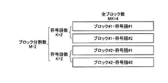
分割部12dは、符号語数Kとブロック分割数Mとに基づき、情報ビット系列をMK個のブロックに分割する。図18は、分割部12dが実施する情報ビット系列の分割の一例を示す図である。図18に示した例では、ブロック分割数M=2、符号語数K=2としている。情報ビット系列はMK個、すなわち4個のブロックに分割される。図18では、説明の便宜上、ブロック分割数M=2に起因して分割された情報ビット系列のかたまりをブロック#1およびブロック#2として表現し、符号語数K=2に起因して分割された情報ビット系列のかたまりを、符号語#1および符号語#2として示している。
The dividing
分割部12dは、分割したMK個のブロックを、それぞれ対応する符号化・シンボル生成処理部111−1〜111−MKへ出力する。符号化・シンボル生成処理部111−j1〜111−MKは、それぞれ実施の形態1の送信機の符号化処理部21およびシンボル生成部22と同様の処理を行い、処理結果をレイヤーマッピング部112へ出力する。
The dividing
レイヤーマッピング部112は、符号化・シンボル生成処理部111−1〜111−MKから入力されたMK個のブロックを、制御部11bから通知されるレイヤーマッピング情報に基づいて、MK個のブロックを各送信アンテナに割当てる。また、レイヤーマッピング部112は、入力されたMK個のブロック(ブロック分割数Mと符号語数Kに基づいて分割されたブロック)を、ブロック分割数Mとレイヤー数Nに基づいたブロックに変換する処理を行う。すなわち、MK個のブロックがMN個のブロック(レイヤー単位のブロック)となるようにブロックの変換を行う。
The
図19は、レイヤーマッピング部112の処理例を示す図である。図18に示した例と同様に、ブロック分割数M=2、符号語数K=2を仮定している。また、送信アンテナ数N=4としている。図19に示した例では、各符号語に対応するブロックを2つのレイヤーに分割することによりサイズの小さいレイヤーを2つ生成することにより、2種類の符号語(符号語#1,#2)を4つのレイヤー(レイヤー#1〜#4)に対応させている。レイヤーマッピング情報には、このような符号語とレイヤーの対応付けの情報が含まれているとする。
FIG. 19 is a diagram illustrating a processing example of the
なお、符号語とレイヤーの対応付け方法は、これに限らず任意の方法とすることができる。たとえば、各符号語に対応するブロックに含まれるシンボルのうち、偶数番目と奇数番目のシンボルを別々のレイヤーに配分するような方式をとってもよいし、符号語に対応するブロックの前半と後半をそれぞれ別のレイヤーに配分するようにしてもよい。レイヤーマッピング部112は、このようにして生成したMN個のブロック(レイヤー単位のブロック)を、それぞれ対応するDFT処理部23−r(r=1,2,…,MN)へ出力する。
Note that the method of associating the codeword with the layer is not limited to this and may be any method. For example, among the symbols included in the block corresponding to each codeword, a method may be used in which even-numbered and odd-numbered symbols are distributed to different layers, and the first half and second half of the block corresponding to the codeword are respectively You may make it distribute to another layer. The
DFT処理部23−rは、入力されたレイヤー単位のブロックに対してDFTを実行し、周波数領域のブロックを生成する。DFT処理部23−rは、生成した周波数領域のブロックを、サブブロック分割部24−rへ出力する。 The DFT processing unit 23-r performs DFT on the input block in units of layers to generate a frequency domain block. The DFT processing unit 23-r outputs the generated frequency domain block to the sub-block dividing unit 24-r.
サブブロック分割部24−rは、入力された周波数領域のブロックを、制御部11bから通知されるサブブロック分割数Lに基づきL個のサブブロックに分割する。サブブロック分割部24−rは、生成したL個のサブブロックを、周波数割当部14aへ出力する。
The sub-block division unit 24-r divides the input frequency domain block into L sub-blocks based on the sub-block division number L notified from the
周波数割当部14aは、サブブロック分割部24−1〜24−MNから入力されたサブブロックを、制御部11bから通知される各送信アンテナに対応する使用周波数情報に基づいてシステム帯域内に割当てる処理を行う。なお、この際、周波数割当部14aは、システム帯域内のその他の周波数帯には何も信号を配置しない。制御部11bは、たとえば、各送信アンテナに対応する使用周波数情報として、送信アンテナ毎に別な周波数帯域にサブブロックを割当てるように使用周波数情報を指示するできることができる。
The
図20は、周波数割当部14aによる周波数割当の例を示す図である。図20では、ブロック分割数M=2、レイヤー数N=4、サブブロック分割数L=2の例を示している。図20では、周波数割り当て121は送信アンテナ間で同じ周波数帯にサブブロックを割当てる例を、周波数割り当て122は、送信アンテナ間で異なる周波数帯にサブブロックを割当てる例を、それぞれ示している。
FIG. 20 is a diagram illustrating an example of frequency allocation by the
また、図20では、サブブロック123−1,123−2はブロック#1,レイヤー#1に対応する周波数領域のブロックから生成される2つのサブブロックを示し、サブブロック124−1,124−2はブロック#2,レイヤー#1に対応する周波数領域のブロックから生成される2つのサブブロックを示す。また、サブブロック125−1,125−2は、ブロック#1,レイヤー#2に対応する周波数領域のブロックから生成される2つのサブブロックを示し、サブブロック126−1,126−2はブロック#2,レイヤー#2に対応する周波数領域のブロックから生成される2つのサブブロックを示す。
In FIG. 20, sub-blocks 123-1 and 123-2 indicate two sub-blocks generated from frequency domain blocks corresponding to block # 1 and layer # 1, and sub-blocks 124-1 and 124-2 are shown. Indicates two sub-blocks generated from blocks in the frequency domain corresponding to block # 2 and layer # 1. Also, sub-blocks 125-1 and 125-2 indicate two sub-blocks generated from frequency domain blocks corresponding to block # 1 and
また、サブブロック127−1,127−2はブロック#1,レイヤー#3に対応する周波数領域のブロックから生成される2つのサブブロックを示し、サブブロック128−1,128−2はブロック#2,レイヤー#3に対応する周波数領域のブロックから生成される2つのサブブロックを示し、サブブロック129−1,129−2はブロック#1,レイヤー#4に対応する周波数領域のブロックから生成される2つのサブブロックを示し、サブブロック130−1,130−2はブロック#2,レイヤー#4に対応する周波数領域のブロックから生成される2つのサブブロックを示している。
Sub-blocks 127-1 and 127-2 indicate two sub-blocks generated from the frequency domain blocks corresponding to block # 1 and
同様に、サブブロック131−1〜131−2はブロック#1,レイヤー#1に対応する周波数領域のブロックから生成される2つのサブブロックを示し、サブブロック132−1,132−2はブロック#2,レイヤー#1に対応する周波数領域のブロックから生成される2つのサブブロックを示している。また、サブブロック133−1,133−2はブロック#1,レイヤー#2に対応する周波数領域のブロックから生成される2つのサブブロックを示し、サブブロック134−1,134−2はブロック#2,レイヤー#2に対応する周波数領域のブロックから生成される2つのサブブロックを示し、サブブロック135−1,135−2はブロック#1,レイヤー#3に対応する周波数領域のブロックから生成される2つのサブブロックを示している。
Similarly, sub-blocks 131-1 to 131-2 indicate two sub-blocks generated from the frequency domain blocks corresponding to block # 1 and layer # 1, and sub-blocks 132-1 and 132-2 represent block #. 2 shows two sub-blocks generated from a block in the frequency domain corresponding to layer # 1. Sub-blocks 133-1 and 133-2 indicate two sub-blocks generated from frequency domain blocks corresponding to block # 1 and
さらにサブブロック136−1,136−2はブロック#2,レイヤー#3に対応する周波数領域のブロックから生成される2つのサブブロックを示し、サブブロック137−1,137−2はブロック#1,レイヤー#4に対応する周波数領域のブロックから生成される2つのサブブロックを示し、サブブロック138−1,138−2はブロック#2,レイヤー#4に対応する周波数領域のブロックから生成される2つのサブブロックを示している。
Further, sub-blocks 136-1 and 136-2 indicate two sub-blocks generated from the frequency domain blocks corresponding to block # 2 and
また、本実施の形態では、周波数の割当ての処理量を削減するために、システム帯域のうち各ブロックが信号送信に使用する周波数帯を限定することとする。たとえば、ブロックごとに使用する周波数帯域を定めておくこととする。周波数割当部14aは、最終的に、送信アンテナ4−g(g=1,2,…,N)に割り当てたサブブロックを、送信アンテナ4−gに対応する逆DFT・CP付加・フレーム生成部113−gへ出力する。
In the present embodiment, in order to reduce the amount of frequency allocation processing, the frequency band used by each block for signal transmission in the system band is limited. For example, a frequency band to be used for each block is determined. The
逆DFT・CP付加・フレーム生成部113−gは、実施の形態1の逆DFT処理部15、CP付加部16、フレーム生成部17および参照信号生成部18の処理と同様の処理を順次実行し、処理結果をD/A変換部2−gへ出力する。なお、参照信号としては、実施の形態1で例示したものと同じものを適用することができるが、必要に応じて参照信号に用いる信号系列を送信アンテナ間で直交したものにしてもよいし、送信アンテナ間で参照信号を同時に同じ周波数を用いて送信しないように調整してもよい。以降の処理は、高周波処理部3−1〜3−N,送信アンテナ4−1〜4−Nの動作は実施の形態1の高周波処理部3,送信アンテナの動作とそれぞれ同様である。
The inverse DFT / CP addition / frame generation unit 113-g sequentially executes the same processes as those of the inverse
図21は、本実施の形態の受信機の機能構成例を示す図である。図21に示すように、本実施の形態の受信機は、受信アンテナ41−1〜41−J(Jは自然数)と、高周波処理部42−1〜42−Jと、A/D変換部43−1〜43−Jと、フレーム分割部44−1〜44−Jと、伝送路推定処理部45−1〜45−Jと、受信信号処理部140と、制御部47aと、で構成される。本実施の形態の受信機が実施の形態1の受信機と異なる点は、受信アンテナから伝送路推定処理部までの一連の構成要素をJ個ずつ備え、更に受信信号処理部140が、送信機でN本の送信アンテナから同時に送信された信号を分離受信する能力を持つ点である。
FIG. 21 is a diagram illustrating a functional configuration example of the receiver according to the present embodiment. As shown in FIG. 21, the receiver according to the present embodiment includes receiving antennas 41-1 to 41-J (J is a natural number), high-frequency processing units 42-1 to 42-J, and A /
制御部47aは、実施の形態1の制御部47の機能に加えて、送信アンテナ毎の使用周波数の情報と、レイヤーマッピング情報と、を受信信号処理部140および伝送路推定処理部45−1〜45−Jに通知する。受信アンテナ41−1〜41−Jは、本実施の形態の送信機から送信された高周波アナログ受信信号を受信する。受信アンテナ41−f(f=1,2,…,J)は、受信した高周波アナログ受信信号を高周波処理部42−fに出力する。以降、高周波処理部42−f,A/D変換部43−f,フレーム分割部44−fは、それぞれ実施の形態の高周波処理部42,A/D変換部43,フレーム分割部44と同様の処理を実施する。
In addition to the function of the control unit 47 of the first embodiment, the
フレーム分割部44−fは、分離した受信信号系列と参照信号系列を、受信信号系列は受信信号処理部140へ、受信参照信号系列は対応する伝送路推定処理部45−fへそれぞれ出力する。
The frame division unit 44-f outputs the separated received signal sequence and reference signal sequence, the received signal sequence to the received
伝送路推定処理部45−fは、実施の形態1の伝送路推定処理部45と同様に、受信参照信号系列からCPを除去し、その結果に対してDFTを行うことで周波数領域の受信参照信号を生成する。その後、受信参照信号系列から、既知シンボルが割り当てられている周波数の信号を抽出し実施の形態1と同様に無線伝送路の周波数伝達関数を算出する。なお、本実施の形態では、送信機はN本の送信アンテナを備えているため、各伝送路推定処理部は、それぞれ、N本の送信アンテナに対応する既知シンボルを用いてN通りの異なる無線伝送路を推定する。伝送路推定処理部45−fは推定したN通りの無線伝送路の周波数伝達関数は、受信信号処理部140へ出力する。
Similarly to the transmission path
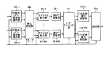
つぎに、受信信号処理部140の動作について詳細に説明する。図22は、受信信号処理部140の構成例を示す図である。図22に示すように、受信信号処理部140は、CP除去・DFT・周波数選択部150−1〜150−Jと、等化処理部64aと、サブブロック結合部65−1〜65−MNと、逆DFT処理部66−1〜66−MNと、レイヤーデマッピング部151と、ビット変換・復号処理部152−1〜152−MKと、結合部69dと、で構成される。
Next, the operation of the received
伝送路推定処理部45−1〜45−Jから受信信号処理部140に入力される無線伝送路の周波数伝達関数は、等化処理部64aに入力される。また、制御部47aから入力されるパラメータのうち、送信アンテナ毎の使用周波数情報はCP除去・DFT・周波数選択部150−1〜150−Jへ、ブロック分割数MはCP除去・DFT・周波数選択部150−1〜150−J、サブブロック結合部65−1〜65−MNおよび結合部69aへ、各ブロックのサブブロック分割数LはCP除去・DFT・周波数選択部150−1〜150−Jおよびサブブロック結合部65−1〜65−MNへ、それぞれ出力される。また、制御部47aから入力されるパラメータのうち、各ブロックに対応する変調方式および符号化方法はビット変換・復号処理部152−1〜152−MKへ、レイヤーマッピング情報はレイヤーデマッピング部151へ、それぞれ入力される。
The frequency transfer function of the wireless transmission path input to the reception
CP除去・DFT・周波数選択部150−fは、フレーム分割部44−fから入力された受信信号系列に対して、送信アンテナ毎の使用周波数情報と、ブロック分割数Mと、サブブロック分割数Lと、に基づき、実施の形態1におけるCP除去部61とDFT処理部62と同様の処理を行い、周波数領域の受信信号を生成する。CP除去・DFT・周波数選択部150−fは、その後、当該周波数領域の受信信号から送信機がサブブロックに割り当てた周波数の信号のみを抽出し、抽出した周波数領域の受信信号を等化処理部64aに出力する。前述したように、本実施の形態では、送信アンテナ間で使用周波数が異なる構成もとりうる。このような場合には、少なくとも1つの送信アンテナについてサブブロックが割り当てられていれば、その周波数の信号は抽出するように処理を行う。
The CP removal / DFT / frequency selection unit 150-f uses the frequency information for each transmission antenna, the block division number M, and the sub-block division number L for the received signal sequence input from the frame division unit 44-f. Based on the above, the same processing as the
等化処理部64aは、入力された周波数領域の受信信号に対して、信号が無線伝送路で受けたひずみを補償するとともに、送信機のN本の送信アンテナから同時に送信された信号を分離する処理を行う。この処理は、実施の形態1の等化処理部64で説明した処理を、複数の送受信アンテナの場合に拡張することで容易に実現できる。たとえば、ある周波数の周波数領域の受信信号をJ本の受信アンテナに対応して並べたJ次元の列ベクトルをXとし、ある周波数の送信信号をN本の送信アンテナに対応して並べたN次元列ベクトルをSとし、ある周波数の無線伝送路の周波数伝達関数を、列番号が送信アンテナ番号に対応し、行番号が受信アンテナ番号に対応するように並べた行列Hとし、受信アンテナで印加される雑音成分をJ次元列ベクトルVで表すとすると、以下の式(5)が成り立つ。
X=HS+V …(5)
The
X = HS + V (5)
すなわち、実施の形態1の等化処理部と同様の考え方で以下の式(6)に示す計算をすることで、信号が無線伝送路で受けたひずみの補償と、信号の分離を実現でき、N系統の周波数領域の送信信号推定値を得ることができる。
H-1X=S+H-1V …(6)
That is, by performing the calculation shown in the following equation (6) in the same way as the equalization processing unit of the first embodiment, it is possible to realize the compensation of the distortion of the signal received in the wireless transmission path and the separation of the signal, N system frequency domain transmission signal estimates can be obtained.
H −1 X = S + H −1 V (6)
N系統の周波数領域の送信信号推定値は、それぞれ対応するサブブロック結合部65−1〜65−MNへ受け渡される。サブブロック結合部65−1〜65−MN,逆DFT処理部66−1〜66−MNは、実施の形態1のサブブロック結合部65−1〜65−M,,逆DFT処理部66−1〜66−Mとそれぞれ同様の処理を行う。逆DFT処理部66−1〜66−MNは、処理によって得られた時間領域の送信シンボルの推定値をレイヤーデマッピング部151へ出力する。
N system frequency domain transmission signal estimation values are transferred to the corresponding sub-block coupling units 65-1 to 65 -MN. The sub-block coupling units 65-1 to 65-MN and the inverse DFT processing units 66-1 to 66-MN are the sub-block coupling units 65-1 to 65-M and the inverse DFT processing unit 66-1 of the first embodiment. The same processing as that for .about.66-M is performed. The inverse DFT processing units 66-1 to 66 -MN output the estimated values of the transmission symbols in the time domain obtained by the processing to the
レイヤーデマッピング部151は、制御部47aから受け取ったレイヤーマッピング情報に基づいて、入力された時間領域の送信シンボルの推定値を、ブロック分割数Mと符号語数Kで表される形に並べ替える。すなわち、レイヤーデマッピング部151は、図17におけるレイヤーマッピング部112の処理と逆の処理を行う。制御部47aから出力されるレイヤーマッピング情報には、送信機が送信時に行った符号語とレイヤーの対応付けについての情報が含まれているとする。レイヤーデマッピング部の処理結果は、それぞれ対応するビット変換・復号処理部152−1〜152−MKへ出力される。
Based on the layer mapping information received from the
ビット変換・復号処理部152−1〜152−MKは、実施の形態1のビット変換部67−1〜67−Mおよび復号部68−1〜68−Mと同様の処理を行い、処理後のブロック毎の情報ビット系列の推定値を、結合部69dに出力する。結合部69dは、送信機の分割部12dが実施した処理と逆の処理を行い、情報ビット系列を復元する。
Bit conversion / decoding processing units 152-1 to 152-MK perform the same processing as bit conversion units 67-1 to 67-M and decoding units 68-1 to 68-M in the first embodiment. The estimated value of the information bit sequence for each block is output to the combining
このように、本実施の形態では、複数の送信アンテナから信号を送信できるようにし、さらに、送信アンテナ間で周波数領域のサブブロックの割当を独立に決定できるようにした。そのため、実施の形態1と同様の効果が得られるとともに、さらに周波数領域のサブブロックの割当方法に柔軟性が増し、結果的に高いSINRで信号伝送が実現できる。 As described above, in this embodiment, signals can be transmitted from a plurality of transmission antennas, and further, assignment of frequency domain sub-blocks can be independently determined between the transmission antennas. Therefore, the same effects as those of Embodiment 1 can be obtained, and the frequency domain sub-block allocation method is more flexible, and as a result, signal transmission can be realized with high SINR.
また、本実施の形態では、周波数割当部14aが制御部11bから通知される各送信アンテナに対応する使用周波数情報に基づいて送信アンテナに対してサブブロックを割り当てるようにしたが、たとえば、各送信アンテナに対するサブブロックの割当を決定した後、割当方法(送信アンテナごとの使用周波数など)を送信タイミングに応じて送信アンテナ間で入れ替えるようにしてもよい。また、割当方法を入れ替えるタイミングも、たとえば送信シンボル単位や、複数の送信シンボルをまとめたスロット単位またはフレーム単位とすることができる。このような構成にすると、受信する信号の品質が平均化され、劣悪な無線伝送環境においてより良好な伝送性能を得ることができる。
In the present embodiment, the
また、本実施の形態では、レイヤー数を送信アンテナ数Nと等しく設定しているが、これに限定されず、レイヤー数を送信アンテナ数と異なる値とすることができる。この場合、レイヤーマッピング部の後段の何れかの位置で、レイヤー単位のサブブロックを送信アンテナに割当てる処理を挿入すればよい。レイヤーマッピング部112とこの処理を行う構成要素をまとめてマッピング手段と考えることができる。このときに、たとえばレイヤー間の位相を調整した後に合成することで送信アンテナに割当てるマルチアンテナプリコーディングの処理を適用してもよい。マルチアンテナプリコーディング処理については、一般的な手法を用いることが可能であり、例えば、3GPP TS36.211V8.6.0に開示されているマルチアンテナプリコーディングの係数を用いることができる。無線伝送路に合わせて適切なプリコーディング係数を用いることで、より高い伝送性能を実現できる。
In the present embodiment, the number of layers is set equal to the number of transmission antennas N, but the present invention is not limited to this, and the number of layers can be set to a value different from the number of transmission antennas. In this case, a process of assigning sub-blocks in units of layers to transmission antennas may be inserted at any position after the layer mapping unit. The
また、実施の形態3で述べたように、本実施の形態の送信機のDFT処理部23−1〜23−MNとサブブロック分割部24−1〜24−MNの間にRRCフィルタ処理部をそれぞれ配置する構成としてもよい。この場合、RRCフィルタ処理部を配置した処理系統から生成される信号のPAPRを抑圧することが可能になる。この場合、受信機でも、サブブロック結合部65−1〜65−MNと逆DFT処理部66−1〜66−MNの間にもそれぞれRRCフィルタ処理部を配置する。 Further, as described in the third embodiment, an RRC filter processing unit is provided between the DFT processing units 23-1 to 23-MN and the sub-block dividing units 24-1 to 24-MN of the transmitter according to the present embodiment. Each may be arranged. In this case, it becomes possible to suppress the PAPR of the signal generated from the processing system in which the RRC filter processing unit is arranged. In this case, also in the receiver, RRC filter processing units are also arranged between the sub-block combining units 65-1 to 65-MN and the inverse DFT processing units 66-1 to 66-MN.
また、送信機の制御部11bから各構成要素に通知される制御信号の内容(ブロック分割数など)を、受信機が生成し、別途用意した通信チャネルを利用して受信機から送信機に制御信号の内容を通知する構成としてもよい。この場合、受信機が複数の送信機に対して制御信号を適切に生成することにより、送信アンテナ間で周波数領域のサブブロックの割当を独立に決定できるように構成した利点を生かして、複数の送信機の送信信号をシステム帯域内で密に配置することが可能になる。
In addition, the contents of the control signal (number of block divisions, etc.) notified to each component from the
以上のように、本発明にかかる送信装置および受信装置は、周波数分割多元接続を採用する通信システムに有用であり、特に、異なる周波数帯に対応した複数のSC−FDMA送信系統を備える送信装置を含む通信システムに適している。 As described above, the transmission apparatus and the reception apparatus according to the present invention are useful for a communication system that employs frequency division multiple access, and in particular, a transmission apparatus including a plurality of SC-FDMA transmission systems corresponding to different frequency bands. Suitable for including communication systems.
1,1a 送信信号生成部、2,2−1〜2−N D/A変換部、3,3−1〜3−N 高周波処理部、4,4−1〜4−N 送信アンテナ、11,11a,11b 制御部、12,12a,12b,12c,12d 分割部、13−1〜13−M サブブロック生成部、14,14a 周波数割当部、15 逆DFT処理部、16 CP付加部、17 フレーム生成部、18 参照信号生成部、21 符号化処理部、22 シンボル生成部、23,23−1〜23−MN DFT処理部、24,24−1〜24−MN サブブロック分割部、31 既知シンボル生成部、32 周波数割当部、33 逆DFT処理部、34 CP付加部、41,41−1〜41−J 受信アンテナ、42,42−1〜42−J 高周波処理部、43,43−1〜43−J A/D変換部、44,44−1〜44−J フレーム分割部、45,45−1〜45−J 伝送路推定処理部、46 受信信号処理部、47,47a 制御部、51,61 CP除去部、52,62 DFT処理部、53,63 周波数選択部、54−1〜54−M 乗算処理部、64,64a 等化処理部、65−1〜65−MN サブブロック結合部、66−1〜66−MN 逆DFT処理部、67−1〜67−M ビット変換部、68−1〜68−M 復号部、69,69a,69b,69c,69d 結合部、71 RRC処理部、81〜84 ブロック、91−1〜91−M RRC処理部、100−1,100−2 ブロック、101−1,101−2,102−1,102−2,103−1〜103−4 サブブロック、111−1〜111−MK 符号化・シンボル生成処理部、112 レイヤーマッピング部、113−1〜113−N 逆DFT・CP付加・フレーム生成部、121,122 周波数割り当て、123−1,123−2,124−1,124−2,125−1,125−2,126−1,126−2,127−1,127−2,128−1,128−2,129−1,129−2,130−1,130−2,131−1,131−2,132−1,132−2,133−1,133−2,134−1,134−2,135−1,135−2,136−1,136−2,137−1,137−2,138−1,138−2 サブブロック、140 受信信号処理部、150−1〜150−J CP除去・DFT・周波数選択部、151 レイヤーデマッピング部、152−1〜152−MK ビット変換・復号処理部、200−1〜200−12 送信信号系列、201−1,201−2 参照信号。 1, 1a transmission signal generation unit, 2, 2-1 to 2-ND conversion unit, 3, 3-1 to 3-N high frequency processing unit, 4, 4-1 to 4-N transmission antenna, 11a, 11b control unit, 12, 12a, 12b, 12c, 12d division unit, 13-1 to 13-M sub-block generation unit, 14, 14a frequency allocation unit, 15 inverse DFT processing unit, 16 CP addition unit, 17 frames Generator, 18 reference signal generator, 21 encoding processor, 22 symbol generator, 23, 23-1 to 23-MN DFT processor, 24, 24-1 to 24-MN sub-block divider, 31 known symbol Generation unit, 32 Frequency allocation unit, 33 Inverse DFT processing unit, 34 CP addition unit, 41, 41-1 to 41-J Receiving antenna, 42, 42-1 to 42-J High frequency processing unit, 43, 43-1 43-JA / D conversion unit, 44, 44-1 to 44-J frame division unit, 45, 45-1 to 45-J transmission path estimation processing unit, 46 received signal processing unit, 47, 47a control unit, 51, 61 CP removal Section, 52, 62 DFT processing section, 53, 63 frequency selection section, 54-1 to 54-M multiplication processing section, 64, 64a equalization processing section, 65-1 to 65-MN sub-block combining section, 66-1 66-MN Inverse DFT processing unit, 67-1 to 67-M bit conversion unit, 68-1 to 68-M decoding unit, 69, 69a, 69b, 69c, 69d coupling unit, 71 RRC processing unit, 81 to 84 Block, 91-1 to 91-M RRC processing unit, 100-1, 100-2 block, 101-1, 101-2, 102-1, 102-2, 103-1 to 103-4 sub-block, 111- 1-111 MK encoding / symbol generation processing unit, 112 layer mapping unit, 113-1 to 113-N inverse DFT / CP addition / frame generation unit, 121, 122 frequency allocation, 123-1, 123-2, 124-1, 124 -2, 125-1, 125-2, 126-1, 126-2, 127-1, 127-2, 128-1, 128-2, 129-1, 129-2, 130-1, 130-2 , 131-1, 131-2, 132-1, 132-2, 133-1, 133-2, 134-1, 134-2, 135-1, 135-2, 136-1, 136-2, 137. -1,137-2,138-1,138-2 sub-block, 140 received signal processing unit, 150-1 to 150-J CP removal / DFT / frequency selection unit, 151 layer demapping unit, 15 -1~152-MK-bit conversion and decoding unit, 200-1~200-12 transmission signal sequence, 201-1 and 201-2 reference signal.
Claims (2)
送信信号系列を1以上の個数のブロックに分割するブロック分割手段と、
前記ブロックに対して離散フーリエ変換処理を行う離散フーリエ変換手段と、
前記離散フーリエ変換処理後のブロックをさらにサブブロックに分割するサブブロック分割手段と、
前記ブロックごとに定められた周波数帯域に基づいて、前記サブブロックを前記送信周波数に割り当てた周波数信号を生成する周波数割当手段と、
前記周波数信号を時間信号に変換する逆離散フーリエ変換手段と、
を備えた送信装置。 A transmission device that converts a transmission digital signal into a high-frequency analog signal and transmits the signal using a plurality of transmission frequencies,
Block dividing means for dividing the transmission signal sequence into one or more blocks;
Discrete Fourier transform means for performing discrete Fourier transform processing on the block;
Sub-block dividing means for further dividing the block after the discrete Fourier transform processing into sub-blocks;
Frequency allocation means for generating a frequency signal in which the sub-block is allocated to the transmission frequency based on a frequency band determined for each block;
Inverse discrete Fourier transform means for transforming the frequency signal into a time signal;
A transmission device comprising:
Priority Applications (1)
| Application Number | Priority Date | Filing Date | Title |
|---|---|---|---|
| JP2013220150A JP2014014191A (en) | 2008-09-18 | 2013-10-23 | Transmitter |
Applications Claiming Priority (3)
| Application Number | Priority Date | Filing Date | Title |
|---|---|---|---|
| JP2008239704 | 2008-09-18 | ||
| JP2008239704 | 2008-09-18 | ||
| JP2013220150A JP2014014191A (en) | 2008-09-18 | 2013-10-23 | Transmitter |
Related Parent Applications (1)
| Application Number | Title | Priority Date | Filing Date |
|---|---|---|---|
| JP2010529686A Division JP5420552B2 (en) | 2008-09-18 | 2009-07-24 | Transmitter and receiver |
Publications (2)
| Publication Number | Publication Date |
|---|---|
| JP2014014191A true JP2014014191A (en) | 2014-01-23 |
| JP2014014191A5 JP2014014191A5 (en) | 2014-06-05 |
Family
ID=42039396
Family Applications (2)
| Application Number | Title | Priority Date | Filing Date |
|---|---|---|---|
| JP2010529686A Expired - Fee Related JP5420552B2 (en) | 2008-09-18 | 2009-07-24 | Transmitter and receiver |
| JP2013220150A Pending JP2014014191A (en) | 2008-09-18 | 2013-10-23 | Transmitter |
Family Applications Before (1)
| Application Number | Title | Priority Date | Filing Date |
|---|---|---|---|
| JP2010529686A Expired - Fee Related JP5420552B2 (en) | 2008-09-18 | 2009-07-24 | Transmitter and receiver |
Country Status (6)
| Country | Link |
|---|---|
| US (1) | US8526512B2 (en) |
| EP (1) | EP2333994B1 (en) |
| JP (2) | JP5420552B2 (en) |
| KR (1) | KR101643434B1 (en) |
| CN (2) | CN104660534B (en) |
| WO (1) | WO2010032554A1 (en) |
Families Citing this family (16)
| Publication number | Priority date | Publication date | Assignee | Title |
|---|---|---|---|---|
| WO2010050383A1 (en) * | 2008-10-31 | 2010-05-06 | シャープ株式会社 | Transmitter apparatus, receiver apparatus and communication system |
| SG171738A1 (en) | 2008-11-14 | 2011-07-28 | Panasonic Corp | Wireless communication terminal apparatus, wireless communication base station apparatus, and cluster constellation setting method |
| US8542781B2 (en) * | 2010-08-31 | 2013-09-24 | Telefonaktiebolaget L M Ericsson (Publ) | Incrementally inclusive frequency domain symbol joint detection |
| EP2640026A1 (en) * | 2012-03-16 | 2013-09-18 | Nec Corporation | Method for estimating the frequency bandwidth of a communication channel |
| FR3009152B1 (en) * | 2013-07-25 | 2015-07-31 | Thales Sa | METHOD OF MANAGING RF FREQUENCIES IN BROADBAND USE |
| US9148182B2 (en) * | 2013-10-09 | 2015-09-29 | Maxlinear, Inc. | Power combining power amplifier architectures and methods |
| KR102384585B1 (en) * | 2013-11-19 | 2022-04-11 | 삼성전자주식회사 | Apparatus and method for scalble video coding in broadcast or communication system |
| CN105027458B (en) * | 2013-12-31 | 2018-11-30 | 华为技术有限公司 | A kind of method, apparatus and system of channel information acquisition |
| US10862634B2 (en) | 2014-03-07 | 2020-12-08 | Huawei Technologies Co., Ltd. | Systems and methods for OFDM with flexible sub-carrier spacing and symbol duration |
| JP6304603B2 (en) * | 2015-09-28 | 2018-04-04 | 日本電信電話株式会社 | Transmitting apparatus, receiving apparatus, communication apparatus, and communication method |
| DE102016102005B4 (en) * | 2016-02-04 | 2018-08-02 | Rheinisch-Westfälische Technische Hochschule Aachen (RWTH) | Circuit arrangement and method for generating a high-frequency, analog transmission signal |
| US10063306B2 (en) * | 2016-10-24 | 2018-08-28 | Mitsubishi Electric Research Laboratories, Inc. | Method and systems using quasi-synchronous distributed CDD systems |
| WO2018163359A1 (en) * | 2017-03-09 | 2018-09-13 | 三菱電機株式会社 | Transmitter apparatus, receiver apparatus, communication system and transmission method |
| CN108631834B (en) * | 2017-03-24 | 2020-12-04 | 电信科学技术研究院 | Method and device for transmitting diversity in multi-antenna communication system |
| EP3544202B1 (en) * | 2018-03-22 | 2021-03-03 | Mitsubishi Electric R&D Centre Europe B.V. | Pre-dft reference signal insertion for single-symbol stbc |
| US10700896B2 (en) | 2018-11-09 | 2020-06-30 | Samsung Electronics Co., Ltd. | Systems and methods for time domain layer separation in orthogonal frequency division multiplexing-based receivers |
Citations (1)
| Publication number | Priority date | Publication date | Assignee | Title |
|---|---|---|---|---|
| WO2008058143A2 (en) * | 2006-11-06 | 2008-05-15 | Qualcomm Incorporated | Methods and apparatus for power allocation and/or rate selection for ul mimo/simo operations with par considerations |
Family Cites Families (17)
| Publication number | Priority date | Publication date | Assignee | Title |
|---|---|---|---|---|
| JP4290917B2 (en) * | 2002-02-08 | 2009-07-08 | 株式会社エヌ・ティ・ティ・ドコモ | Decoding device, encoding device, decoding method, and encoding method |
| US8102907B2 (en) * | 2005-04-28 | 2012-01-24 | Qualcomm Incorporated | Space-frequency equalization for oversampled received signals |
| US20070004465A1 (en) * | 2005-06-29 | 2007-01-04 | Aris Papasakellariou | Pilot Channel Design for Communication Systems |
| WO2007078146A1 (en) * | 2006-01-06 | 2007-07-12 | Samsung Electronics Co., Ltd. | Method and apparatus for transmitting/receiving uplink signaling information in a single carrier fdma system |
| CN103297371B (en) * | 2006-02-08 | 2018-01-16 | 联想创新有限公司(香港) | Single carrier transmitting system, communicator and for single carrier transmission method therein |
| TW200735560A (en) * | 2006-02-10 | 2007-09-16 | Interdigital Tech Corp | Method and apparatus for performing uplink transmission in a multiple-input multiple-output single carrier frequency division multiple access system |
| KR101260836B1 (en) * | 2006-02-28 | 2013-05-06 | 삼성전자주식회사 | Pre-coding method for providing diversity gain in an orthogonal frequency division multiplexing system and transmitting apparatus and method using the same |
| US7916775B2 (en) * | 2006-06-16 | 2011-03-29 | Lg Electronics Inc. | Encoding uplink acknowledgments to downlink transmissions |
| WO2008007506A1 (en) | 2006-07-10 | 2008-01-17 | Osaka University | Transfer method, transfer system, transmitter apparatus and receiver apparatus |
| EP1879293B1 (en) * | 2006-07-10 | 2019-02-20 | Harman Becker Automotive Systems GmbH | Partitioned fast convolution in the time and frequency domain |
| CA2673671C (en) | 2006-12-28 | 2013-12-24 | Sharp Kabushiki Kaisha | Base station device, transmission device, wireless communication system, processor, and wireless communication method |
| US8009727B2 (en) * | 2007-02-20 | 2011-08-30 | Telefonaktiebolaget Lm Ericsson (Publ) | Equalizer for single carrier FDMA receiver |
| CN101874370B (en) | 2007-11-26 | 2014-04-16 | 夏普株式会社 | Radio communication system, radio transmission device, radio communication method, and program |
| JP2011525321A (en) * | 2008-06-12 | 2011-09-15 | ノーテル・ネットワークス・リミテッド | System and method for SC-FDMA transmission diversity |
| KR100987458B1 (en) * | 2008-06-24 | 2010-10-13 | 엘지전자 주식회사 | Method for transmitting uplink signal |
| EP2296331B1 (en) * | 2009-09-15 | 2013-09-11 | Telefonaktiebolaget LM Ericsson (publ) | Technique for SC-FDMA signal generation |
| CN101656697B (en) * | 2009-09-18 | 2013-04-03 | 南京信息工程大学 | Frequency-domain blind equalization method (T/2FF-CMA) based on T/2 fraction space |
-
2009
- 2009-07-24 CN CN201510061928.5A patent/CN104660534B/en active Active
- 2009-07-24 EP EP09814399.3A patent/EP2333994B1/en active Active
- 2009-07-24 KR KR1020117008694A patent/KR101643434B1/en active IP Right Grant
- 2009-07-24 WO PCT/JP2009/063275 patent/WO2010032554A1/en active Application Filing
- 2009-07-24 US US13/119,890 patent/US8526512B2/en active Active
- 2009-07-24 JP JP2010529686A patent/JP5420552B2/en not_active Expired - Fee Related
- 2009-07-24 CN CN200980136505.8A patent/CN102160311B/en active Active
-
2013
- 2013-10-23 JP JP2013220150A patent/JP2014014191A/en active Pending
Patent Citations (1)
| Publication number | Priority date | Publication date | Assignee | Title |
|---|---|---|---|---|
| WO2008058143A2 (en) * | 2006-11-06 | 2008-05-15 | Qualcomm Incorporated | Methods and apparatus for power allocation and/or rate selection for ul mimo/simo operations with par considerations |
Non-Patent Citations (5)
| Title |
|---|
| JPN6009047367; Panasonic: 'Consideration on Multicarrier Transmission scheme for LTE-Adv uplink' 3GPP TSG RAN WG1 Meeting #53bis R1-082398 , 20080630, pp.1-3 * |
| JPN6009047369; LG Electronics: 'Uplink MIMO Transmission for LTE-Advanced' 3GPP TSG RAN WG1 Meeting #54 R1-082943, 20080818 * |
| JPN6009047371; LG Electronics: 'Uplink multiple access schemes for LTE-A' 3GPP TSG RAN WG1 Meeting #54 R1-082945, 20080818 * |
| JPN6009047373; Mitsubishi Electric: 'Uplink Multiple Access for LTE-Advanced' 3GPP TSG RAN WG1 Meeting #54 R1-082776, 20080818 * |
| JPN6009047374; Nokia Siemens Networks, Nokia: 'Uplink Multiple access for LTE-Advanced' 3GPP TSG RAN WG1 Meeting #53bis R1-082609, 20080630 * |
Also Published As
| Publication number | Publication date |
|---|---|
| KR101643434B1 (en) | 2016-07-27 |
| EP2333994A1 (en) | 2011-06-15 |
| US8526512B2 (en) | 2013-09-03 |
| CN102160311A (en) | 2011-08-17 |
| EP2333994B1 (en) | 2017-03-29 |
| CN104660534B (en) | 2018-02-09 |
| JPWO2010032554A1 (en) | 2012-02-09 |
| CN104660534A (en) | 2015-05-27 |
| EP2333994A4 (en) | 2013-05-08 |
| CN102160311B (en) | 2015-03-11 |
| JP5420552B2 (en) | 2014-02-19 |
| US20110176622A1 (en) | 2011-07-21 |
| WO2010032554A1 (en) | 2010-03-25 |
| KR20110074540A (en) | 2011-06-30 |
Similar Documents
| Publication | Publication Date | Title |
|---|---|---|
| JP5420552B2 (en) | Transmitter and receiver | |
| US11700162B2 (en) | Peak-to-average-power reduction for OFDM multiple access | |
| JP5044165B2 (en) | Transmitter, receiver and method in a multi-antenna wireless communication system | |
| CN101243667B (en) | Pilot and data transmission in a MIMO system applying subband multiplexing | |
| KR101658776B1 (en) | Communication device and communication method | |
| US20170070377A1 (en) | User terminal, radio base station, and radio communication method | |
| WO2012115232A1 (en) | Receiving device, transmitting device, receiving method, transmitting method, program, and wireless communication system | |
| JP2008283288A (en) | Radio transmission device and method | |
| JP2012070366A (en) | Transmitter, receiver, relaying device, communication system, transmission method, reception method, relaying method, communication method, computer program, and semiconductor chip | |
| US9912515B2 (en) | Packet transmission method and apparatus for use in filter bank-based multi-carrier wireless communication | |
| KR102542702B1 (en) | Methods and apparatus of repeated transmission for multicarrier wireless communication systems | |
| JP2015164259A (en) | Radio base station, user terminal, radio communication method, and radio communication system | |
| WO2010050383A1 (en) | Transmitter apparatus, receiver apparatus and communication system | |
| JP4732947B2 (en) | OFDM communication system, OFDM communication method, OFDM signal transmitting apparatus, and OFDM signal receiving apparatus | |
| WO2009003420A1 (en) | A method, apparatus and system for implementing the multiple access | |
| JP5630898B2 (en) | Base station apparatus, terminal apparatus, and radio communication system | |
| TWI741050B (en) | Sending device, sending method, receiving device, and receiving method | |
| JP2012060633A (en) | Transmitter, receiver, method, and program for rotation orthogonal code based spectrum aggregation | |
| WO2019198282A1 (en) | Communication device, method, program, and recording medium | |
| JP5259809B2 (en) | Transmitter, receiver and method in a multi-antenna wireless communication system | |
| JP2011155674A (en) | Wireless communication system, wireless communication equipment and wireless communication method |
Legal Events
| Date | Code | Title | Description |
|---|---|---|---|
| A621 | Written request for application examination |
Free format text: JAPANESE INTERMEDIATE CODE: A621 Effective date: 20131023 |
|
| A521 | Written amendment |
Free format text: JAPANESE INTERMEDIATE CODE: A523 Effective date: 20140422 |
|
| A977 | Report on retrieval |
Free format text: JAPANESE INTERMEDIATE CODE: A971007 Effective date: 20140820 |
|
| A131 | Notification of reasons for refusal |
Free format text: JAPANESE INTERMEDIATE CODE: A131 Effective date: 20140902 |
|
| A131 | Notification of reasons for refusal |
Free format text: JAPANESE INTERMEDIATE CODE: A131 Effective date: 20141125 |
|
| A521 | Written amendment |
Free format text: JAPANESE INTERMEDIATE CODE: A523 Effective date: 20150123 |
|
| A02 | Decision of refusal |
Free format text: JAPANESE INTERMEDIATE CODE: A02 Effective date: 20150224 |
|
| A521 | Written amendment |
Free format text: JAPANESE INTERMEDIATE CODE: A523 Effective date: 20150521 |
|
| A911 | Transfer to examiner for re-examination before appeal (zenchi) |
Free format text: JAPANESE INTERMEDIATE CODE: A911 Effective date: 20150529 |
|
| A912 | Re-examination (zenchi) completed and case transferred to appeal board |
Free format text: JAPANESE INTERMEDIATE CODE: A912 Effective date: 20150710 |