JP2014009651A - Hydraulic motor with speed reducer - Google Patents
Hydraulic motor with speed reducer Download PDFInfo
- Publication number
- JP2014009651A JP2014009651A JP2012148257A JP2012148257A JP2014009651A JP 2014009651 A JP2014009651 A JP 2014009651A JP 2012148257 A JP2012148257 A JP 2012148257A JP 2012148257 A JP2012148257 A JP 2012148257A JP 2014009651 A JP2014009651 A JP 2014009651A
- Authority
- JP
- Japan
- Prior art keywords
- carrier
- fixed case
- hydraulic motor
- case
- side groove
- Prior art date
- Legal status (The legal status is an assumption and is not a legal conclusion. Google has not performed a legal analysis and makes no representation as to the accuracy of the status listed.)
- Granted
Links
- 239000003638 chemical reducing agent Substances 0.000 title claims abstract description 13
- 230000007246 mechanism Effects 0.000 claims abstract description 50
- 230000002093 peripheral effect Effects 0.000 claims abstract description 32
- 230000009467 reduction Effects 0.000 claims description 37
- 230000008878 coupling Effects 0.000 abstract description 8
- 238000010168 coupling process Methods 0.000 abstract description 8
- 238000005859 coupling reaction Methods 0.000 abstract description 8
- 238000003754 machining Methods 0.000 abstract description 2
- 238000004519 manufacturing process Methods 0.000 description 5
- 230000013011 mating Effects 0.000 description 5
- 230000000694 effects Effects 0.000 description 3
- 238000000034 method Methods 0.000 description 3
- 230000009471 action Effects 0.000 description 2
- 238000010276 construction Methods 0.000 description 2
- 238000005553 drilling Methods 0.000 description 2
- 230000015572 biosynthetic process Effects 0.000 description 1
- 239000006185 dispersion Substances 0.000 description 1
- 238000003780 insertion Methods 0.000 description 1
- 230000037431 insertion Effects 0.000 description 1
- 230000004048 modification Effects 0.000 description 1
- 238000012986 modification Methods 0.000 description 1
- 230000002265 prevention Effects 0.000 description 1
- 230000008569 process Effects 0.000 description 1
Images


Abstract
Description
本発明は、減速機付きの油圧モータに関する。 The present invention relates to a hydraulic motor with a reduction gear.
減速機構を構成するキャリアを油圧モータの固定ケースに連結する技術としては、例えば特許文献1、2に記載されたものがある。特許文献1に記載された減速機付き油圧モータは、油圧モータ1のハウジング12(固定ケース)と減速機2のホルダ23(キャリア)との合わせ面に複数のボルト穴を形成し、当該複数のボルト穴に減速機2側からボルト5を締結することにより、ホルダ23をハウジング12に連結するものである。
As a technique for connecting the carrier constituting the speed reduction mechanism to the fixed case of the hydraulic motor, for example, there are those described in Patent Documents 1 and 2. The hydraulic motor with a reduction gear described in Patent Document 1 is formed with a plurality of bolt holes on the mating surfaces of the housing 12 (fixed case) of the hydraulic motor 1 and the holder 23 (carrier) of the reduction gear 2, The holder 23 is connected to the
また、特許文献2に記載された減速機付き油圧モータは、キャリア33の鍔部の内周面をモータケーシング3(固定ケース)の外周面に形成された軸スプライン3Dに噛合させることにより、キャリア33をモータケーシング3に連結するものである。
Moreover, the hydraulic motor with a reduction gear described in Patent Document 2 is configured so that the inner peripheral surface of the flange portion of the
特許文献1に記載されたモータ付き減速機においては、ハウジング12とホルダ23との合わせ面にてハウジング12とホルダ23とを連結しているため、以下の問題が生じるおそれがある。
In the reduction gear with a motor described in Patent Document 1, since the
まず、合わせ面の面積は、ハウジング12やホルダ23の大きさや形状によって定まるものであり、限りがあるため、連結用のボルト5を多く設けることができない。合わせ面にボルト穴を形成する場合、強度低下や縁部の欠け等防止の観点からハウジング12やホルダ23の外周よりも十分内側にボルト穴を形成する必要があり、周方向に沿って十分な数のボルト5を配設できない。
First, since the area of the mating surface is determined by the size and shape of the
また、ボルト5にかかる力は、ハウジング12やホルダ23の中心に近いほど大きくなる。そのため、できるだけ中心からの距離をとってボルト5を配置することが好ましい。
Further, the force applied to the
特許文献2に記載されたモータ付き減速機においては、軸スプライン3Dによりキャリア33をモータケーシング3の外周面に連結しているので上記のような問題が生じることはない。しかしながら、スプライン結合の場合、スプラインを形成するための加工に時間がかかる。また、スプライン形成用の専用加工機が必要となる。すなわち、スプライン結合を採用した場合、製造単価が高くなるという問題がある。
In the reduction gear with a motor described in Patent Document 2, the
本発明は、上記課題に鑑みてなされたものであって、その目的は、連結力を十分に確保でき、且つ加工性にも優れた、油圧モータの固定ケースと減速機構のキャリアとの連結構造を備える減速機付きモータを提供することである。 The present invention has been made in view of the above problems, and its object is to provide a coupling structure between a fixed case of a hydraulic motor and a carrier of a speed reduction mechanism, which can sufficiently secure a coupling force and is excellent in workability. It is providing the motor with a reduction gear provided with this.
本発明の減速機付き油圧モータは、内部に油圧モータ機構が配置され、固定ピンの周面が当接するケース側溝が外周面に形成される固定ケースと、前記固定ケースに回転自在に支持される回転ケースと、前記回転ケースの内部に配置されるとともに前記油圧モータ機構の出力軸に連結される減速機構と、を備える。前記減速機構は、前記出力軸に連結される太陽歯車と、前記太陽歯車から前記油圧モータ機構の出力が伝達される出力歯車と、前記固定ピンの周面が当接するキャリア側溝が鍔部の内周面に形成される、前記出力歯車を回転自在に保持するキャリアと、を有する。前記固定ケースと前記キャリアとが重ね合わせられた状態で、前記固定ケースの一部にまで到達する孔が前記固定ケースとは反対側から前記キャリアにあけられることにより、前記ケース側溝と前記キャリア側溝とが同時加工で形成される。そして、前記ケース側溝と前記キャリア側溝とで形成された空間に前記固定ピンが挿入されることにより、前記キャリアが前記固定ケースに連結される。 The hydraulic motor with a speed reducer according to the present invention includes a hydraulic motor mechanism disposed therein, a fixed case in which a case side groove with which a peripheral surface of a fixed pin abuts is formed on the outer peripheral surface, and is rotatably supported by the fixed case. A rotation case; and a speed reduction mechanism that is disposed inside the rotation case and coupled to the output shaft of the hydraulic motor mechanism. The speed reduction mechanism includes a sun gear connected to the output shaft, an output gear to which the output of the hydraulic motor mechanism is transmitted from the sun gear, and a carrier side groove with which a peripheral surface of the fixed pin abuts in the flange portion. And a carrier formed on a peripheral surface for rotatably holding the output gear. In the state where the fixed case and the carrier are overlapped, a hole reaching the part of the fixed case is opened in the carrier from the side opposite to the fixed case, so that the case side groove and the carrier side groove Are formed by simultaneous processing. The carrier is connected to the fixed case by inserting the fixing pin into a space formed by the case side groove and the carrier side groove.
本発明によれば、固定ケースの外周面に固定ピンが配置されるので、固定ケースとキャリアとの合わせ面に固定ピンを設ける場合に比べて、固定ピンを多く設けることができる。また、ケース側溝とキャリア側溝とが同時加工で形成されるので、固定ピンが挿入されるケース側溝とキャリア側溝との芯ズレを抑制できる。これらにより、固定ケースとキャリアとの連結力を十分に確保できる。また、ケース側溝およびキャリア側溝を形成するためのキャリアの孔あけ加工は、一般的な加工機械で可能である。すなわち、本発明における固定ケースとキャリアとの連結構造は、その製作における加工性にも優れている。 According to the present invention, since the fixing pins are arranged on the outer peripheral surface of the fixing case, more fixing pins can be provided than in the case where the fixing pins are provided on the mating surface of the fixing case and the carrier. Moreover, since the case side groove and the carrier side groove are formed simultaneously, it is possible to suppress the misalignment between the case side groove into which the fixing pin is inserted and the carrier side groove. As a result, a sufficient coupling force between the fixed case and the carrier can be secured. Also, the carrier can be drilled to form the case side groove and the carrier side groove with a general processing machine. That is, the connection structure between the fixed case and the carrier in the present invention is excellent in workability in the production.
以下、本発明を実施するための形態について図面を参照しつつ説明する。図1〜5は、減速機付き油圧モータ1を説明するための図である。 Hereinafter, embodiments for carrying out the present invention will be described with reference to the drawings. 1-5 is a figure for demonstrating the hydraulic motor 1 with a reduction gear.
(減速機付き油圧モータ)
減速機付き油圧モータ1は、図1に示すように、油圧モータ2と、減速機3(遊星減速機)とを有している。この減速機付き油圧モータ1は、例えば油圧ショベルなどの建設車両における走行装置などに用いられるものである。なお、建設車両用の用途に限定されるものではない。
(Hydraulic motor with reduction gear)
As shown in FIG. 1, the hydraulic motor 1 with a speed reducer has a hydraulic motor 2 and a speed reducer 3 (planetary speed reducer). The hydraulic motor 1 with a reduction gear is used for a traveling device in a construction vehicle such as a hydraulic excavator, for example. In addition, it is not limited to the use for construction vehicles.
(油圧モータ)
油圧モータ2は、油圧モータ機構5と、油圧モータ機構5を内部に収容する固定ケース4とを有している。
(Hydraulic motor)
The hydraulic motor 2 includes a
固定ケース4は、有底円筒状のケーシングであり、底部11の中央部分には油圧モータ機構5の出力軸13を挿通するための孔12が設けられている。
The
油圧モータ機構5は、上述した出力軸13を有するモータ部分であり、固定ケース4の内部に配置されている。そして、この出力軸13により油圧モータ機構5の出力が減速機3に伝達されるようになっている。なお、油圧モータ機構5としては、公知のものを用いることができ、本願においてはその説明を割愛している。
The
(減速機)
減速機3は、減速機構7(遊星減速機構)と、減速機構7を内部に収容する回転ケース6とを有している。
(Decelerator)
The
回転ケース6は、中空円筒状のケーシングであり、その一方の開口部側から固定ケース4の底部11側が挿入されている。また、他方の開口部は、蓋21によって閉じられている。この回転ケース6は、固定ケース4の外周と回転ケース6の内周との間に配置された軸受22a・22bを介して固定ケース4に回転自在に支持されている。
The rotating case 6 is a hollow cylindrical casing, and the
減速機構7は、回転ケース6の内部に配置されるとともに、油圧モータ機構5の出力軸13に連結されており、第1太陽歯車24(太陽歯車)、第1遊星歯車25、第1キャリア26、第2太陽歯車27、第2遊星歯車28(出力歯車)、第2キャリア29(キャリア)、および内歯30を有している。減速機構7は、油圧モータ機構5の出力を回転速度を減速しながら伝達し、最終的に回転ケース6を回転駆動することで、当該回転ケース6のフランジ部31に取り付けられたスプロケット(不図示)を介して非駆動部(不図示)を駆動する。
The
第1太陽歯車24は、油圧モータ機構5の出力軸13の端部に連結されており、出力軸13と共に回転するようになっている。
The
第1遊星歯車25は、第1太陽歯車24の周囲に複数個配置されており、各々第1太陽歯車24と噛合している。これらの第1遊星歯車25は、第1キャリア26に対して回転自在に保持されている。これにより、各第1遊星歯車25は、自転しながら第1太陽歯車24の周囲を公転するようになっている。また、各第1遊星歯車25は、回転ケース6の内周に形成された内歯30にも噛合するよう配置されている。
A plurality of first
第1キャリア26は、第1遊星歯車25を回転自在に保持する部材であり、第2太陽歯車27とスプライン結合されている。第2太陽歯車27は、出力軸13が内挿される円筒部材であり、第1キャリア26の他、複数個の第2遊星歯車28とも噛合している。
The
第2遊星歯車28(出力歯車)は、第1太陽歯車24から第1遊星歯車25、第1キャリア26、および第2太陽歯車27を介して伝達された油圧モータ機構5の出力を、内歯30を介して回転ケース6に伝達する歯車である。
The second planetary gear 28 (output gear) outputs the output of the
この第2遊星歯車28は、第2キャリア29に対して回転自在に保持されている。また、第2遊星歯車28は、内歯30にも噛合するよう配置されている。
The second
第2キャリア29は、第2遊星歯車28を回転自在に保持する部材である。第2キャリア29は、詳細は後述するが、油圧モータ2の固定ケース4に、第2キャリア29が固定ケース4に対して固定ケース4の少なくとも周方向に変位しないように連結されている。固定ケース4とは反対側の第2キャリア29の端面29a(図3参照)には、第2遊星歯車28を回転自在に保持する複数の柱部53が形成されている。なお、図3に示した第2キャリア29の単品図は、図1に示す矢印Bの方向で図1中の第2キャリア29をみたときの図である。
The
(減速機構部の各歯車の動き)
上記のように構成された減速機3の作動について記載しておく。固定ケース4の内部に配置された油圧モータ機構5が回転すると、その出力軸13に結合された第1太陽歯車24が回転して、この第1太陽歯車24に噛合している各第1遊星歯車25が内歯30と噛合しながら、第1太陽歯車24の周りで公転運動を行う。この第1遊星歯車25の公転運動に伴って第1キャリア26が回転し、第1キャリア26とスプライン結合された第2太陽歯車27が回転する。この第2太陽歯車27が回転することで、第2キャリア29に回転自在に保持された各第2遊星歯車28が回転(自転)し、これにより、第2遊星歯車28と内歯30との噛合を介して、回転ケース6が回転駆動される。
(Movement of each gear of the speed reduction mechanism)
The operation of the
(固定ケースとキャリアとの連結)
固定ケース4と第2キャリア29との連結について詳しく説明する。
(Connection between fixed case and carrier)
The connection between the fixed
固定ケース4と第2キャリア29とは、第2キャリア29の鍔部41の内周面42に複数形成されたキャリア側溝43と、固定ケース4の底部11の外周面44に複数形成されたケース側溝45とで形成された空間に挿入された円柱形状の固定ピン51によって連結されている。なお、第2キャリア29の鍔部41は、図1に示すように、第2キャリア29の外周部から出力軸13の軸方向、かつ油圧モータ機構5側に延在する環状の鍔である。
The fixed
<キャリア側溝およびケース側溝の形成>
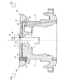
図4、5を参照しつつ、キャリア側溝43およびケース側溝45の形成方法についてまず説明する。図4のうちの右側の図(F4a)は、固定ケース4および第2キャリア29の加工状態を示す断面図であり、図4のうちの左側の図(F4b)は、その後、固定ケース4と第2キャリア29とが固定ピン51で連結された状態を示す断面図である。図5は、図4のA部拡大図である。
<Formation of carrier side groove and case side groove>
First, a method for forming the
第2キャリア29の内側部分には、重ね合わせられた固定ケース4の側に突出する環状の凸部61が設けられている。また、固定ケース4の底部11における内側部分(孔12部分)の端には、凸部61と当接する環状の凹部62が設けられている。凸部61と凹部62とで、第2キャリア29の軸心と固定ケース4の軸心とを合わせるための軸心調整機構を形成する。
On the inner side portion of the
固定ケース4に設けられた凹部62は円錐形状とされている。そのテーパ面62aは、固定ケース4の軸心方向に対してα度の角度で傾斜している。αの値は、例えば30以上90未満である。本実施形態では30度のテーパ面となっている。なお、10≦α<90であってもよいし、さらには、0<α<90であってもよい。
The
第2キャリア29に設けられた凸部61の外周面もテーパ面61aとされている。第2キャリア29の軸心方向に対してのテーパ面61aの傾斜角度は、固定ケース4の凹部62のテーパ面62aの傾斜角度(α度)と同じとされる。
The outer peripheral surface of the
ここで、図4のうちの右側の図に示したように、固定ケース4の底部11に第2キャリア29を重ね合わせたときに、固定ケース4の凹部62と第2キャリア29の凸部61とのみで、固定ケース4と第2キャリア29とが接触するように、凸部61(第2キャリア29)および凹部62(固定ケース4)は形成される。すなわち、固定ケース4の底部11に第2キャリア29を重ね合わせたとき、固定ケース4の軸心方向においては、固定ケース4と第2キャリア29との間には例えば隙間Sがあく。また、固定ケース4の軸心方向に直交する方向においては、固定ケース4の底部11の外周面44と第2キャリア29の鍔部41の内周面42との間にも隙間があく。なお、凹部62のテーパ面62aと凸部61のテーパ面61aとは同じ傾斜角度であるため、テーパ面62aとテーパ面61aとの間には隙間があかず、凹部62と凸部61とは面接触する。
Here, as shown in the right side of FIG. 4, when the
凹部62と凸部61と(軸心調整機構)により、固定ケース4の底部11の上に第2キャリア29を重ね合わせたとき、第2キャリア29の軸心と固定ケース4の軸心とは一致(合致)する。
When the
このようにして固定ケース4と第2キャリア29とを軸心同一で重ね合わせ、例えばねじ棒63およびナット64により固定ケース4と第2キャリア29とを固定する。この状態で、固定ケース4の一部にまで到達する複数の孔52を固定ケース4とは反対側から第2キャリア29に対して垂直にあける。図3に示したように、本実施形態では、孔52は第2キャリア29の柱部53の間にあけられている(本実施形態では、計15個の孔52があけられている)。
In this way, the fixed
この孔52をあけることにより、キャリア側溝43とケース側溝45とが同時に形成される。すなわち、孔52の直径と、キャリア側溝43およびケース側溝45で形成される孔の直径とは当然等しい。
By making this
<固定ケースとキャリアの組み付け>
第2キャリア29を固定ケース4に組み付けるにあたっては、まず、固定ケース4の底部11の外周に設けられた環状の溝33に、所定の厚みのロックワッシャー32を取り付ける。そして、固定ケース4の底部11に第2キャリア29を重ね合わせ、ケース側溝45とキャリア側溝43とで形成された空間に固定ピン51を挿入して、固定ケース4と第2キャリア29とを連結する。固定ピン51の挿入は、圧入であってもよいし緩挿であってもよい。これにより、第2キャリア29は固定ケース4に対して固定ケース4の少なくとも周方向に変位しないように連結される。
<Assembly of fixed case and carrier>
In assembling the
(作用・効果)
本発明によれば、固定ケースの外周面に固定ピンが配置されるので、特許文献1に記載の減速機付き油圧モータよりも固定ピンを多く設けることができる。また、ケース側溝とキャリア側溝とが同時加工で形成されるので、固定ピンが挿入されるケース側溝とキャリア側溝との芯ズレを抑制できる。これにより、複数の固定ピンに作用する力のばらつきは極小に抑えられる。その結果、特定の固定ピンに大きな力が作用して摩耗することでその耐久性が低下することを極小に抑えられる。これらにより、固定ケースとキャリアとの連結力を十分に確保できる。
(Action / Effect)
According to the present invention, since the fixing pins are arranged on the outer peripheral surface of the fixing case, more fixing pins can be provided than the hydraulic motor with a reduction gear described in Patent Document 1. Moreover, since the case side groove and the carrier side groove are formed simultaneously, it is possible to suppress the misalignment between the case side groove into which the fixing pin is inserted and the carrier side groove. Thereby, the dispersion | variation in the force which acts on several fixing pins is suppressed to the minimum. As a result, it is possible to minimize a decrease in durability due to a large force acting on the specific fixing pin and being worn. As a result, a sufficient coupling force between the fixed case and the carrier can be secured.
また、ケース側溝およびキャリア側溝を形成するためのキャリアの孔あけ加工は、一般的な加工機械で可能である。すなわち、本発明における固定ケースとキャリアとの連結構造は、その製作における加工性にも優れている。 Also, the carrier can be drilled to form the case side groove and the carrier side groove with a general processing machine. That is, the connection structure between the fixed case and the carrier in the present invention is excellent in workability in the production.
本実施形態では、ケース側溝とキャリア側溝とを形成するための孔をキャリアの柱部の間にあけている。この部分は薄肉部であるため加工が容易である。すなわち、加工性をされに向上させることができている。 In the present embodiment, holes for forming the case side groove and the carrier side groove are formed between the carrier pillars. Since this part is a thin part, processing is easy. That is, the workability can be improved.
また、本実施形態では、キャリアの軸心と固定ケースの軸心とを合わせた状態で前記孔をあける。これにより、固定ピンを用いて固定ケースにキャリアを連結した状態において、キャリアの軸心と固定ケースの軸心とは一致する。これにより、減速機内部の歯車などの構成部品が回転動作した際に歯車の噛合いが均一にならないことを防止でき、製品寿命がばらつくことを抑制できる。 Moreover, in this embodiment, the said hole is opened in the state which match | combined the axial center of the carrier and the axial center of the fixed case. Thereby, in the state which connected the carrier to the fixing case using the fixing pin, the axis of the carrier coincides with the axis of the fixing case. Thereby, when components, such as a gear in a reduction gear, rotate, it is possible to prevent the gears from being uniformly meshed, and to prevent the product life from varying.
また、キャリアの軸心と固定ケースの軸心とを合わせる軸心調整機構が設けられているので、容易に軸心合わせを行うことができる。 In addition, since an axis adjustment mechanism for aligning the axis of the carrier and the axis of the fixed case is provided, the axis can be easily aligned.
本実施形態では、キャリアの内側部分に形成された環状の凸部および固定ケースの内側部分に形成された円錐形状の凹部というように、キャリアおよび固定ケースの一部分に軸心調整機構を形成したことから、軸心調整(軸心合わせ)用の部品を別途、必要としない。その分、製造コストを抑えることができるとともに、軸心合わせをより容易に行うことができる。 In this embodiment, the shaft center adjusting mechanism is formed in a part of the carrier and the fixed case, such as an annular convex part formed in the inner part of the carrier and a conical concave part formed in the inner part of the fixed case. Therefore, there is no need for separate parts for adjusting the shaft center. Accordingly, the manufacturing cost can be reduced, and the axis alignment can be performed more easily.
また、本実施形態では、固定ケースの底部の外周にロックワッシャーを取り付けて、連結状態において、キャリアに形成された環状の凸部と固定ケースに形成された円錐形状の凹部とが接触しないようにされている。これにより、これら凸部・凹部が摩耗することがないので、分解・組立を繰り返し行っても、軸心合わせのための凸部・凹部の形状を微修正などする必要はない。 Further, in this embodiment, a lock washer is attached to the outer periphery of the bottom portion of the fixed case so that the annular convex portion formed on the carrier and the conical concave portion formed on the fixed case do not contact in the connected state. Has been. As a result, since these convex portions and concave portions do not wear, it is not necessary to finely correct the shape of the convex portions and concave portions for axial alignment even when repeated disassembly and assembly.
(変形例)
固定ピン51は必ずしも円柱形状である必要はない。同様に、固定ピン51の周面が当接するケース側溝45およびキャリア側溝43の内周面は必ずしも円弧(略半円)である必要はない。例えば、楕円柱形状、四角柱形状などの固定ピン51であってもよい。この場合、ケース側溝45およびキャリア側溝43も固定ピン51に面接触する形状とするため、これらの溝を同時形成するための孔52の形状は、真円ではなく、楕円、四角形などとなる。
(Modification)
The fixing
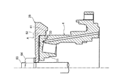
(軸心調整機構の他の形態)
図6、7を参照しつつ軸心調整機構の他の形態について説明する。本実施形態では、固定ピン51が配置される固定ケース4の外周部分、および固定ピン51が配置される第2キャリア29の内周部分に軸心調整機構を形成している。
(Other forms of shaft center adjustment mechanism)
Another embodiment of the shaft center adjusting mechanism will be described with reference to FIGS. In the present embodiment, the shaft center adjusting mechanism is formed on the outer peripheral portion of the fixing
具体的には、固定ケース4の底部11の外周面をテーパ面44a(ケース側テーパ面)とし、第2キャリア29の鍔部41の内周面をテーパ面44a(ケース側テーパ面)に沿うテーパ面42a(キャリア側テーパ面)としている。このテーパ面44a(ケース側テーパ面)とテーパ面42a(キャリア側テーパ面)とで、第2キャリア29の軸心と固定ケース4の軸心とを合わせる軸心調整機構を形成している。
Specifically, the outer peripheral surface of the bottom 11 of the fixed
固定ケース4の底部の外周に形成されたテーパ面44aは、固定ケース4の軸心方向において第2キャリア29の側に縮径する環状のテーパ面である。このテーパ面44aは、固定ケース4の軸心方向に対してβ度の角度で傾斜している。βの値は、例えば1以上30未満である。本実施形態では3度のテーパ面となっている。なお、0<β<30であってもよい。
A tapered
第2キャリア29の鍔部41の内周に形成されたテーパ面42aは、第2キャリア29の軸心方向において固定ケース4の側に拡径する環状のテーパ面である。第2キャリア29の軸心方向に対してのテーパ面42aの傾斜角度は、固定ケース4のテーパ面44aの傾斜角度(β度)と同じとされる。
The tapered
また、図6、7に示したように、固定ケース4の底部11に第2キャリア29を重ね合わせたときに、固定ケース4に形成されたテーパ面44aと第2キャリア29に形成されたテーパ面42aとのみで、固定ケース4と第2キャリア29とが接触するように、第2キャリア29および固定ケース4は形成される。すなわち、固定ケース4の底部11に第2キャリア29を重ね合わせたとき、固定ケース4の軸心方向において、固定ケース4と第2キャリア29との間には隙間があく。なお、テーパ面44aとテーパ面42aとは同じ傾斜角度であるため、これらの面の間には隙間があかず、テーパ面44aとテーパ面42aとは面接触する。
As shown in FIGS. 6 and 7, when the
これらテーパ面44a・44b(軸心調整機構)により、固定ケース4の底部11の上に第2キャリア29を重ね合わせたとき、第2キャリア29の軸心と固定ケース4の軸心とを容易に一致させることができる。
When the
(作用・効果)
本実施形態によると、円錐面(テーパ面)の接触面積を大きくとることができるため、軸心合わせ時のガタツキが抑えられる。そのため、キャリアと固定ケースとの軸心合わせがより容易となる。さらには、孔あけ加工(ケース側溝およびキャリア側溝の同時加工)の際に工具の刃からの力が作用する部分が接触(テーパ面44a・44b)しているため、孔あけ加工時のガタツキも抑えられる。すなわち、この軸心調整機構によると、製作における加工性をさらに向上させることができる。
(Action / Effect)
According to the present embodiment, since the contact area of the conical surface (tapered surface) can be increased, backlash at the time of axial alignment is suppressed. For this reason, it is easier to align the center of the carrier and the fixed case. Furthermore, since the part where the force from the blade of the tool acts is in contact (tapered
また、円錐面(テーパ面)の接触面積を大きくとることができるため、テーパ面の傾斜角度を先の実施形態のものよりも小さくすることができる、という効果もある。 In addition, since the contact area of the conical surface (tapered surface) can be increased, there is an effect that the inclination angle of the tapered surface can be made smaller than that of the previous embodiment.
1 減速機付き油圧モータ
2 油圧モータ
3 減速機
4 固定ケース
5 油圧モータ機構
6 回転ケース
7 減速機構
13 出力軸
24 第1太陽歯車(太陽歯車)
28 第2遊星歯車(出力歯車)
29 第2キャリア(キャリア)
41 鍔部
42 内周面
43 キャリア側溝
44 外周面
45 ケース側溝
51 固定ピン
52 孔
DESCRIPTION OF SYMBOLS 1 Hydraulic motor with reduction gear 2
28 Second planetary gear (output gear)
29 Second career (carrier)
41
Claims (6)
前記固定ケースに回転自在に支持される回転ケースと、
前記回転ケースの内部に配置されるとともに前記油圧モータ機構の出力軸に連結される減速機構と、
を備え、
前記減速機構は、
前記出力軸に連結される太陽歯車と、
前記太陽歯車から前記油圧モータ機構の出力が伝達される出力歯車と、
前記固定ピンの周面が当接するキャリア側溝が鍔部の内周面に形成される、前記出力歯車を回転自在に保持するキャリアと、
を有し、
前記固定ケースと前記キャリアとが重ね合わせられた状態で、前記固定ケースの一部にまで到達する孔が前記固定ケースとは反対側から前記キャリアにあけられることにより、前記ケース側溝と前記キャリア側溝とが同時加工で形成され、
前記ケース側溝と前記キャリア側溝とで形成された空間に前記固定ピンが挿入されることにより、前記キャリアが前記固定ケースに連結されることを特徴とする減速機付き油圧モータ。 A fixed case in which a hydraulic motor mechanism is arranged and a case side groove with which the peripheral surface of the fixed pin abuts is formed on the outer peripheral surface;
A rotating case rotatably supported by the fixed case;
A speed reduction mechanism disposed inside the rotating case and coupled to the output shaft of the hydraulic motor mechanism;
With
The deceleration mechanism is
A sun gear coupled to the output shaft;
An output gear to which the output of the hydraulic motor mechanism is transmitted from the sun gear;
A carrier side groove with which the peripheral surface of the fixing pin abuts is formed on the inner peripheral surface of the flange, and the carrier that rotatably holds the output gear;
Have
In the state where the fixed case and the carrier are overlapped, a hole reaching the part of the fixed case is opened in the carrier from the side opposite to the fixed case, so that the case side groove and the carrier side groove Are formed by simultaneous processing,
A hydraulic motor with a reduction gear, wherein the carrier is connected to the fixed case by inserting the fixing pin into a space formed by the case side groove and the carrier side groove.
前記固定ケースとは反対側の前記キャリアの端面には、前記出力歯車を回転自在に保持する複数の柱部が形成されており、
前記柱部の間に前記孔があけられることを特徴とする減速機付き油圧モータ。 In the hydraulic motor with a reduction gear according to claim 1,
On the end surface of the carrier on the side opposite to the fixed case, a plurality of column portions that rotatably hold the output gear are formed,
The hydraulic motor with a reduction gear, wherein the hole is formed between the pillar portions.
前記キャリアの軸心と前記固定ケースの軸心とが合わせられた状態で前記孔があけられることを特徴とする減速機付き油圧モータ。 In the hydraulic motor with a reduction gear according to claim 1 or 2,
The hydraulic motor with a reduction gear, wherein the hole is formed in a state where the axis of the carrier and the axis of the fixed case are aligned.
前記キャリアの軸心と前記固定ケースの軸心とを合わせる軸心調整機構が設けられていることを特徴とする減速機付き油圧モータ。 In the hydraulic motor with a reduction gear according to claim 3,
A hydraulic motor with a reduction gear, characterized in that an axis adjustment mechanism for aligning the axis of the carrier and the axis of the fixed case is provided.
前記軸心調整機構は、
前記キャリアの内側部分で前記固定ケースの側に突出するように前記キャリアに形成された環状の凸部と、
前記固定ケースの内側部分に形成された前記凸部と当接する凹部と、
を有することを特徴とする減速機付き油圧モータ。 In the hydraulic motor with a reduction gear according to claim 4,
The axis adjusting mechanism is
An annular projection formed on the carrier so as to protrude toward the fixed case at the inner portion of the carrier;
A concave portion that abuts against the convex portion formed on the inner portion of the fixed case;
A hydraulic motor with a speed reducer characterized by comprising:
前記軸心調整機構は、
前記固定ケースの外周面に形成され、前記キャリアの側に縮径するケース側テーパ面と、
前記ケース側テーパ面に沿うように前記キャリアの前記鍔部の内周面に形成され、前記固定ケースの側に拡径するキャリア側テーパ面と、
を有することを特徴とする減速機付き油圧モータ。 In the hydraulic motor with a reduction gear according to claim 4,
The axis adjusting mechanism is
A case-side tapered surface formed on the outer peripheral surface of the fixed case and having a diameter reduced toward the carrier;
A carrier-side taper surface that is formed on the inner peripheral surface of the flange portion of the carrier so as to be along the case-side taper surface, and expands toward the fixed case;
A hydraulic motor with a speed reducer characterized by comprising:
Priority Applications (1)
| Application Number | Priority Date | Filing Date | Title |
|---|---|---|---|
| JP2012148257A JP6038510B2 (en) | 2012-07-02 | 2012-07-02 | Hydraulic motor with reduction gear and method of manufacturing hydraulic motor with reduction gear |
Applications Claiming Priority (1)
| Application Number | Priority Date | Filing Date | Title |
|---|---|---|---|
| JP2012148257A JP6038510B2 (en) | 2012-07-02 | 2012-07-02 | Hydraulic motor with reduction gear and method of manufacturing hydraulic motor with reduction gear |
Publications (2)
| Publication Number | Publication Date |
|---|---|
| JP2014009651A true JP2014009651A (en) | 2014-01-20 |
| JP6038510B2 JP6038510B2 (en) | 2016-12-07 |
Family
ID=50106558
Family Applications (1)
| Application Number | Title | Priority Date | Filing Date |
|---|---|---|---|
| JP2012148257A Active JP6038510B2 (en) | 2012-07-02 | 2012-07-02 | Hydraulic motor with reduction gear and method of manufacturing hydraulic motor with reduction gear |
Country Status (1)
| Country | Link |
|---|---|
| JP (1) | JP6038510B2 (en) |
Cited By (1)
| Publication number | Priority date | Publication date | Assignee | Title |
|---|---|---|---|---|
| JP2016113948A (en) * | 2014-12-15 | 2016-06-23 | 株式会社不二越 | Hydraulic travel motor with speed-reducer |
Citations (6)
| Publication number | Priority date | Publication date | Assignee | Title |
|---|---|---|---|---|
| JPS6280059U (en) * | 1985-11-08 | 1987-05-22 | ||
| JPH09257107A (en) * | 1996-03-19 | 1997-09-30 | Kayaba Ind Co Ltd | Hydraulic motor with reduction gear |
| JPH09280323A (en) * | 1996-04-09 | 1997-10-28 | Kubota Corp | Wheel motor |
| JP2002213568A (en) * | 2000-11-16 | 2002-07-31 | Nabco Ltd | Travel unit |
| JP2007002895A (en) * | 2005-06-22 | 2007-01-11 | Nabtesco Corp | Bearing pre-load mechanism of reducer |
| JP4532250B2 (en) * | 2004-12-09 | 2010-08-25 | 日立建機株式会社 | Hydraulic motor with reduction gear |
-
2012
- 2012-07-02 JP JP2012148257A patent/JP6038510B2/en active Active
Patent Citations (6)
| Publication number | Priority date | Publication date | Assignee | Title |
|---|---|---|---|---|
| JPS6280059U (en) * | 1985-11-08 | 1987-05-22 | ||
| JPH09257107A (en) * | 1996-03-19 | 1997-09-30 | Kayaba Ind Co Ltd | Hydraulic motor with reduction gear |
| JPH09280323A (en) * | 1996-04-09 | 1997-10-28 | Kubota Corp | Wheel motor |
| JP2002213568A (en) * | 2000-11-16 | 2002-07-31 | Nabco Ltd | Travel unit |
| JP4532250B2 (en) * | 2004-12-09 | 2010-08-25 | 日立建機株式会社 | Hydraulic motor with reduction gear |
| JP2007002895A (en) * | 2005-06-22 | 2007-01-11 | Nabtesco Corp | Bearing pre-load mechanism of reducer |
Cited By (1)
| Publication number | Priority date | Publication date | Assignee | Title |
|---|---|---|---|---|
| JP2016113948A (en) * | 2014-12-15 | 2016-06-23 | 株式会社不二越 | Hydraulic travel motor with speed-reducer |
Also Published As
| Publication number | Publication date |
|---|---|
| JP6038510B2 (en) | 2016-12-07 |
Similar Documents
| Publication | Publication Date | Title |
|---|---|---|
| EP2034219B1 (en) | Reduction gear | |
| JP5910378B2 (en) | Deceleration mechanism and motor rotational force transmission device having the same | |
| JP2014101967A (en) | Wheel driving device | |
| JP2009162337A (en) | Power transmission device | |
| JP5762882B2 (en) | Gear device | |
| JP5844628B2 (en) | Planetary gear device and method of manufacturing planetary gear device | |
| JP6727034B2 (en) | Gear reducer | |
| JP6487664B2 (en) | Differential | |
| CN102782362B (en) | Gearing | |
| EP3270003A1 (en) | Gear device | |
| JP2016080152A5 (en) | ||
| JP2012127470A (en) | Planetary gear speed reducer | |
| CN107664175B (en) | Gear device | |
| JP6038510B2 (en) | Hydraulic motor with reduction gear and method of manufacturing hydraulic motor with reduction gear | |
| JP2015064064A (en) | Planetary reduction gear, and method for fixing internal gear in planetary reduction gear | |
| CN109751366B (en) | Planetary gear speed reducer | |
| JP6220206B2 (en) | Planetary reducer | |
| WO2009110023A1 (en) | Eccentric speed reducer | |
| CN103890452B (en) | Gear drive | |
| JP4610242B2 (en) | Joint structure of gear and rotating shaft, and planetary gear reducer using the same | |
| JP2010180976A (en) | Differential device | |
| CN107202100B (en) | Gear device | |
| JP2010031955A (en) | Shaft member and differential device | |
| JP6182428B2 (en) | Planetary gear reduction device and manufacturing method thereof | |
| JP2014009650A (en) | Hydraulic motor with speed reducer |
Legal Events
| Date | Code | Title | Description |
|---|---|---|---|
| RD03 | Notification of appointment of power of attorney |
Free format text: JAPANESE INTERMEDIATE CODE: A7423 Effective date: 20150407 |
|
| A521 | Request for written amendment filed |
Free format text: JAPANESE INTERMEDIATE CODE: A821 Effective date: 20150415 |
|
| RD04 | Notification of resignation of power of attorney |
Free format text: JAPANESE INTERMEDIATE CODE: A7424 Effective date: 20150415 |
|
| A621 | Written request for application examination |
Free format text: JAPANESE INTERMEDIATE CODE: A621 Effective date: 20150417 |
|
| A977 | Report on retrieval |
Free format text: JAPANESE INTERMEDIATE CODE: A971007 Effective date: 20160204 |
|
| A131 | Notification of reasons for refusal |
Free format text: JAPANESE INTERMEDIATE CODE: A131 Effective date: 20160209 |
|
| A521 | Request for written amendment filed |
Free format text: JAPANESE INTERMEDIATE CODE: A523 Effective date: 20160401 |
|
| TRDD | Decision of grant or rejection written | ||
| A01 | Written decision to grant a patent or to grant a registration (utility model) |
Free format text: JAPANESE INTERMEDIATE CODE: A01 Effective date: 20161004 |
|
| A61 | First payment of annual fees (during grant procedure) |
Free format text: JAPANESE INTERMEDIATE CODE: A61 Effective date: 20161102 |
|
| R150 | Certificate of patent or registration of utility model |
Ref document number: 6038510 Country of ref document: JP Free format text: JAPANESE INTERMEDIATE CODE: R150 |
|
| R250 | Receipt of annual fees |
Free format text: JAPANESE INTERMEDIATE CODE: R250 |
|
| R250 | Receipt of annual fees |
Free format text: JAPANESE INTERMEDIATE CODE: R250 |
|
| R250 | Receipt of annual fees |
Free format text: JAPANESE INTERMEDIATE CODE: R250 |
|
| R250 | Receipt of annual fees |
Free format text: JAPANESE INTERMEDIATE CODE: R250 |
|
| R250 | Receipt of annual fees |
Free format text: JAPANESE INTERMEDIATE CODE: R250 |