JP2014007785A - Drain dustproof device - Google Patents
Drain dustproof device Download PDFInfo
- Publication number
- JP2014007785A JP2014007785A JP2012139636A JP2012139636A JP2014007785A JP 2014007785 A JP2014007785 A JP 2014007785A JP 2012139636 A JP2012139636 A JP 2012139636A JP 2012139636 A JP2012139636 A JP 2012139636A JP 2014007785 A JP2014007785 A JP 2014007785A
- Authority
- JP
- Japan
- Prior art keywords
- water passage
- lower case
- housing
- passage hole
- case portion
- Prior art date
- Legal status (The legal status is an assumption and is not a legal conclusion. Google has not performed a legal analysis and makes no representation as to the accuracy of the status listed.)
- Pending
Links
Images


Landscapes
- Installation Of Bus-Bars (AREA)
Abstract
Description
本発明は、ビルや工場などに設置される受変電設備において、その受変電設備の各種機器同士を繋ぐバスダクトに設置された水抜き防塵装置に関する。 The present invention relates to a drainage and dustproof device installed in a bus duct connecting various devices of a power receiving / transforming facility in a power receiving / transforming facility installed in a building or a factory.
例えば、ビルや工場などに設置される受変電設備には、スイッチギヤや変圧器などの各種機器がある。これら各種機器のうち、例えばスイッチギヤと変圧器とを屋内外で電気的に接続する手段としてバスダクトが利用されている。このバスダクトは、スイッチギヤと変圧器とを電気的に接続する帯板状導体を碍子などの絶縁性支持部材で支持した構造を具備する。 For example, power receiving / transforming equipment installed in buildings and factories includes various devices such as switch gears and transformers. Among these various devices, for example, a bus duct is used as means for electrically connecting a switch gear and a transformer indoors and outdoors. The bus duct has a structure in which a strip plate conductor that electrically connects the switchgear and the transformer is supported by an insulating support member such as an insulator.
この種のバスダクトが設置される周囲環境、特に屋外において、ダクト内部への雨水の侵入やダクト内部での結露によりダクト内部の湿度が上昇すると、帯板状導体を絶縁性支持部材で支持した構造における絶縁性能が低下するおそれがある。このような絶縁性能が低下すると、地絡事故が発生する原因となる。 A structure in which a strip plate conductor is supported by an insulating support member when the humidity inside the duct rises due to rainwater entering the duct or condensation inside the duct in the surrounding environment where this type of bus duct is installed, especially outdoors. There is a risk that the insulation performance in the case will deteriorate. When such insulation performance is degraded, a ground fault occurs.
そこで、バスダクトに水抜き装置を設置することが有効な手段となる(例えば、特許文献1参照)。この特許文献1で開示された水抜き装置は、ダクト底部にねじ孔を設け、そのねじ孔に雄ねじをねじ込んだ構造を具備する。その雄ねじの凹部に多数の粒状物を収容し、雄ねじのダクト外側部位に粒状物の径よりも小さい径の孔を形成すると共に、雄ねじのダクト内側部位に粒状物の径よりも小さい径の孔が形成された蓋を装着した構造を具備する。 Therefore, it is effective to install a water draining device in the bus duct (see, for example, Patent Document 1). The water draining device disclosed in Patent Document 1 has a structure in which a screw hole is provided in a duct bottom and a male screw is screwed into the screw hole. A large number of granular materials are accommodated in the concave portion of the male screw, and a hole having a diameter smaller than the diameter of the granular material is formed in the outer portion of the duct of the male screw, and a hole having a diameter smaller than that of the granular material is formed in the inner portion of the duct of the male screw. It has a structure with a lid on which is formed.
この水抜き装置では、粒状物相互間の隙間を通ってダクト内で溜まった水がダクト外へ排出される。この排水効果と共に、粒状物相互間の位置がずれていることにより、雄ねじおよび蓋に形成された孔の一部を閉塞することで、ダクト外から粉塵などの異物がダクト内へ侵入することが阻止される。このようにして、排水効果と防塵効果の両方を兼ね備えた水抜き装置が提案されている。 In this water draining device, the water accumulated in the duct passes through the gap between the granular materials and is discharged out of the duct. Along with this drainage effect, the position between the particulates is shifted, and by closing a part of the hole formed in the male screw and the lid, foreign matters such as dust can enter the duct from outside the duct. Be blocked. In this way, a water draining device having both a drainage effect and a dustproof effect has been proposed.
ところで、前述の特許文献1に開示された水抜き装置は、ダクト底部にねじ孔を設け、そのねじ孔に雄ねじをねじ込んだ構造を具備する。このようなねじ込み式の水抜き装置では、受変電設備のスイッチギヤと変圧器とを繋ぐバスダクトに適用することが非常に困難である。 By the way, the drainage device disclosed in the above-mentioned Patent Document 1 has a structure in which a screw hole is provided in the bottom of the duct and a male screw is screwed into the screw hole. Such a screw-type water draining device is very difficult to apply to a bus duct that connects a switchgear of a power receiving / transforming facility and a transformer.
つまり、ビルや工場に既に設置された既存のバスダクトにねじ孔を形成することは非常に困難である。また、バスダクト底部の板厚も薄いものであることから、そのような薄い板厚のバスダクト底部にねじ孔を形成すること自体も非常に困難である。 That is, it is very difficult to form a screw hole in an existing bus duct already installed in a building or factory. In addition, since the thickness of the bus duct bottom is thin, it is very difficult to form a screw hole in the bus duct bottom having such a thin thickness.
そこで、本発明は前述の問題点に鑑みて提案されたもので、その目的とするところは、簡易な構造によりバスダクトへの適用が容易で、所期の排水性能および防塵性能を発揮し得る水抜き防塵装置を提供することにある。 Therefore, the present invention has been proposed in view of the above-described problems, and the object of the present invention is to provide a water structure that can be easily applied to a bus duct with a simple structure and can exhibit the desired drainage performance and dustproof performance. The object is to provide a dustproof device.
前述の目的を達成するための技術的手段として、本発明に係る水抜き防塵装置は、筐体の底板部に密着状態で取り付けられ、その筐体の底板部に形成された第一通水孔と連通する第二通水孔を有する板状のベース部と、そのベース部に固着された筒状の上ケース部と、その上ケース部に着脱自在に装着され、底部に第三通水孔を有する有底筒状の下ケース部と、ベース部、上ケース部および下ケース部で囲まれた内部空間に配置され、その内部空間での通水通路を迷流構造とする仕切り部材とで構成されたことを特徴とする。 As a technical means for achieving the above-mentioned object, the drainage dustproof device according to the present invention is attached in close contact with the bottom plate portion of the casing, and the first water passage hole formed in the bottom plate portion of the casing. A plate-like base portion having a second water passage communicating with the base, a cylindrical upper case portion fixed to the base portion, and a detachable attachment to the upper case portion, and a third water passage hole at the bottom A bottomed cylindrical lower case portion having a base member, an inner space surrounded by a base case, an upper case portion, and a lower case portion, and a partition member having a water passage in the inner space as a stray flow structure It is structured.
本発明では、筐体の底板部およびベース部に第一通水孔および第二通水孔を形成すると共に下ケース部の底部に第三通水孔を形成し、ベース部、上ケース部および下ケース部からなる内部空間に配置された仕切り部材によりその内部空間での通水通路を迷流構造としたことにより、筐体の内部に貯溜した水を下ケース部の第三通水孔から速やかに排出することができると共に、粉塵や水などの異物が筐体の内部に侵入することを阻止できる。このようにして所期の排水性能および防塵性能を兼ね備えた機能を発揮すると共に、筐体の底板部に形成する第一通水孔をねじ孔とする必要がないので、既設の筐体に水抜き防塵装置を設置することが容易であり、また、その筐体の底板部の板厚が薄い場合であっても水抜き防塵装置の設置が容易となる。 In the present invention, the first water passage hole and the second water passage hole are formed in the bottom plate portion and the base portion of the housing, and the third water passage hole is formed in the bottom portion of the lower case portion. The partition member arranged in the internal space consisting of the lower case portion has a water flow passage in the internal space having a labyrinth structure, so that water stored in the housing is discharged from the third water flow hole in the lower case portion. While being able to discharge | emit quickly, foreign materials, such as dust and water, can be prevented from entering the inside of the housing. In this way, the desired drainage performance and dustproof performance can be achieved, and the first water passage hole formed in the bottom plate portion of the housing does not need to be a screw hole. It is easy to install the draining dustproof device, and even when the thickness of the bottom plate portion of the casing is thin, the draining dustproof device can be easily installed.
本発明における仕切り部材は、下ケース部に収容された多数の球体で構成されていることが望ましい。このように、多数の球体で仕切り部材を構成すれば、筐体の内部に貯溜した水は、球体相互間の隙間を通って下ケース部の第三通水孔から外部へ速やかに排出されると共に、粉塵や水などの異物は、球体が下ケース部の第三通水孔の一部を閉塞すると共に球体からなる迷流構造でもって筐体の内部に侵入することを阻止される。 The partition member in the present invention is preferably composed of a large number of spheres accommodated in the lower case portion. Thus, if a partition member is comprised with many spheres, the water stored inside the housing | casing will be rapidly discharged | emitted outside from the 3rd water flow hole of a lower case part through the clearance gap between spheres. At the same time, foreign substances such as dust and water are blocked from entering the inside of the housing by the stray flow structure formed by the sphere while the sphere blocks a part of the third water passage hole of the lower case portion.
本発明におけるベース部は、筐体の第一通水孔よりも小径の第二通水孔を筐体の第一通水孔の周縁複数箇所に配置することにより、第一通水孔と第二通水孔との重合部分で開口させた構造が望ましい。このように、筐体の第一通水孔の一部をベース部で閉塞すると共にベース部の第二通水孔の一部を筐体で閉塞し、そのベース部の第二通水孔と筐体の第一通水孔との重合部分のみで開口させれば、極小の開口部分を形成することが容易となり、所期の排水性能と防塵性能の両方を兼ね備えた機能を容易に発揮させることができる。 In the base portion of the present invention, the second water passage holes having a diameter smaller than that of the first water passage hole of the housing are arranged at a plurality of positions on the periphery of the first water passage hole of the housing. A structure opened at a polymerization portion with two water passage holes is desirable. In this way, a part of the first water passage hole of the housing is closed by the base portion, and a part of the second water passage hole of the base portion is closed by the housing, and the second water passage hole of the base portion is If it is opened only at the overlapping part with the first water passage hole of the housing, it becomes easy to form a very small opening part, and easily achieve the function that has both the desired drainage performance and dustproof performance. be able to.
本発明では、下ケース部を上ケース部に着脱自在に装着する構造として、上ケース部の内壁面に雌ねじを形成すると共に下ケース部の外壁面に雄ねじを形成し、下ケース部を上ケース部に内挿することにより螺合させた構造が望ましい。このような構造を採用すれば、上ケース部に対する下ケース部の着脱が容易となって、上ケース部および下ケース部の内部を容易に清掃したり、その内部空間に配置された仕切り部材を容易に交換することができる。また、下ケース部のねじ込み量に応じて内部空間の容積を調整することも可能となる。 In the present invention, as a structure in which the lower case portion is detachably attached to the upper case portion, a female screw is formed on the inner wall surface of the upper case portion and a male screw is formed on the outer wall surface of the lower case portion. A structure that is screwed into the part by insertion is desirable. By adopting such a structure, it becomes easy to attach and detach the lower case part with respect to the upper case part, and the inside of the upper case part and the lower case part can be easily cleaned, or the partition member disposed in the internal space can be removed. Can be easily replaced. It is also possible to adjust the volume of the internal space in accordance with the screwing amount of the lower case part.
本発明では、上ケース部に対して下ケース部を固定する緩み止め機構を設けた構造が望ましい。このように、緩み止め機構を設ければ、振動などの衝撃が加わっても上ケース部から下ケース部が脱落することを確実に防止でき、耐震性能に優れた水抜き防塵装置を提供することができる。 In the present invention, a structure provided with a locking mechanism for fixing the lower case part to the upper case part is desirable. In this way, by providing a locking mechanism, it is possible to reliably prevent the lower case part from dropping off from the upper case part even when an impact such as vibration is applied, and to provide a drainage dustproof device with excellent earthquake resistance. Can do.
本発明によれば、筐体の底板部およびベース部に第一通水孔および第二通水孔を形成すると共に下ケース部の底部に第三通水孔を形成し、ベース部、上ケース部および下ケース部からなる内部空間に配置された仕切り部材によりその内部空間での通水通路を迷流構造としたことにより、筐体内部に貯溜した水を下ケース部の第三通水孔から速やかに排出することができると共に、粉塵や水などの異物が筐体の内部に侵入することを阻止できる。 According to the present invention, the first water passage hole and the second water passage hole are formed in the bottom plate portion and the base portion of the casing, and the third water passage hole is formed in the bottom portion of the lower case portion. The water flow passage in the internal space is made into a stray flow structure by the partition member arranged in the internal space consisting of the upper and lower case parts, so that the water stored in the housing is made into the third water flow hole in the lower case part. Can be quickly discharged, and foreign substances such as dust and water can be prevented from entering the housing.
このようにして所期の排水性能および防塵性能を兼ね備えた機能を発揮すると共に、筐体の底板部に形成する第一通水孔をねじ孔とする必要がないので、既設の筐体に水抜き防塵装置を設置することが容易であり、また、その筐体の底板部の板厚が薄い場合であっても水抜き防塵装置の設置が容易となる。 In this way, the desired drainage performance and dustproof performance can be achieved, and the first water passage hole formed in the bottom plate portion of the housing does not need to be a screw hole. It is easy to install the draining dustproof device, and even when the thickness of the bottom plate portion of the casing is thin, the draining dustproof device can be easily installed.
本発明に係る水抜き防塵装置の実施形態を以下に詳述する。なお、以下の実施形態では、ビルや工場などに設置される受変電設備の各種機器のうち、スイッチギヤと変圧器とを屋内外で電気的に接続するバスダクトに適用した場合を例示する。なお、本発明は、バスダクト以外の他の構造を具備する筐体に適用可能である。 Embodiments of the drainage dustproof device according to the present invention will be described in detail below. In addition, in the following embodiment, the case where it applies to the bus duct which electrically connects a switchgear and a transformer among the various apparatuses of a receiving / transforming installation installed in a building, a factory, etc. indoors and outdoors is illustrated. The present invention is applicable to a housing having a structure other than the bus duct.
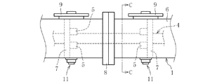
この実施形態におけるバスダクト1は、図9に示すように、スイッチギヤ2と変圧器3とを屋内外で電気的に接続する筐体構造をなし、図10および図11に示すようにスイッチギヤ2と変圧器3とを電気的に接続する帯板状導体4(図では三相)を碍子やブッシングなどの絶縁性支持部材5で支持した構造を具備する。この帯板状導体4を支持する絶縁性支持部材5は、筐体6の内部に架設された支持フレーム7に取り付けられている。この種のバスダクト1は、外部からの水や粉塵などの異物が筐体6の内部に侵入することを阻止するため、筐体同士を連結するための接続部8や筐体内を点検するための点検部9にパッキンを装着した密閉構造とすることにより防塵性能を発揮させている。
The bus duct 1 in this embodiment has a housing structure that electrically connects the
また、この種のバスダクト1が設置される周囲環境、特に屋外において、ダクト内部への雨水の侵入やダクト内部での結露によりダクト内部の湿度が上昇すると、帯板状導体4を絶縁性支持部材5で支持した構造における絶縁性能が低下するおそれがある。このような絶縁性能が低下すると、地絡事故が発生する原因となる。このような地絡事故発生を未然に防止するため、バスダクト1の筐体6に水抜き防塵装置11を設置することが有効な手段となる。
Further, when the humidity inside the duct rises due to the intrusion of rainwater into the inside of the duct or condensation inside the duct in the surrounding environment where this type of bus duct 1 is installed, particularly outdoors, the
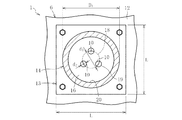
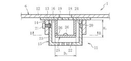
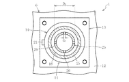
この実施形態における水抜き防塵装置11は、図1および図2に示すように、バスダクト1の筐体6の底板部12に密着状態で取り付けられた板状のベース部13と、そのベース部13に固着された筒状の上ケース部14と、その上ケース部14に着脱自在に装着された有底筒状の下ケース部15と、ベース部13、上ケース部14および下ケース部15で囲まれた内部空間16に配置された仕切り部材としての多数個の球体17とで主要部が構成されている。
As shown in FIGS. 1 and 2, the
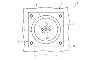
ベース部13は、図3に示すように正方形状(一辺L=100mm)をなし、ステンレス等の金属製素材で構成されている。このベース部13はパッキン(図示せず)を介してバスダクト1の筐体6の底板部12にボルト止めすることにより密着状態で取り付けられる。そのボルト止めはベース部13の四隅としている。ここで、バスダクト1の筐体6の底板部12には、円形状をなす第一通水孔18(直径d1=8mm)が形成されている。これに対して、ベース部13の中央部位には、円形状をなす三個の第二通水孔19(直径d2=5mm)が形成されている。
As shown in FIG. 3, the
ベース部13に形成された三つの第二通水孔19は、バスダクト1の筐体6の底板部12に形成された第一通水孔18の周縁で円周方向等間隔(120°等配)に配置されている。このように、ベース部13で第一通水孔18の一部を閉塞すると共に筐体6の底板部12で第一通水孔18(d1=8mm)よりも小径の第二通水孔19(d2=5mm)の一部を閉塞することにより、筐体6の第一通水孔18と、ベース部13の第二通水孔19との重合部分のみで開口させることにより、極小の開口部10(水抜き部)を形成している。
Three second water passage holes 19 formed in the
上ケース部14は、円筒形状(外径D1=60mm、高さH1=20mm)をなし、ステンレス等の金属製素材で構成されている。この上ケース部14は、溶接によりベース部13に固着されている。なお、上ケース部14とベース部13とは一体的に形成された単一の素材で構成することも可能である。
The
上ケース部14の内壁面には、雌ねじ20が刻設されている。この上ケース部14の周壁部には、下ケース部15を固定するための緩み止め機構としてねじ21が螺着されている。このねじ21の先端は上ケース部14の内壁面から突出退入自在となっている。
A
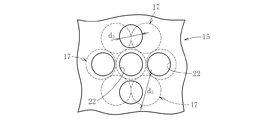
下ケース部15は、有底円筒形状(外径D2=48mm、高さH2=30mm)をなし、ステンレス等の金属製素材で構成されている。この下ケース部15の底部の中央部位には、円形状をなす五個の第三通水孔22(直径d3=5mm)が形成されている。これら第三通水孔22は、図4に示すように、底部の中心に形成された一個の通水孔22と、その周囲で中心位置が直径d4=12mmの円周上で等間隔(90°等配)に形成された四個の通水孔22とで構成されている。
The
この下ケース部15は、その外壁面に雄ねじ23が刻設され、上ケース部14に内挿することにより上ケース部14の雌ねじ20と螺合するねじ込み式となっている。また、下ケース部15の周壁部には、上ケース部14に対して固定するための緩み止め機構として凹溝24が形成されている。この凹溝24にねじ21の先端が嵌入することにより下ケース部15の脱落を防止する。
The
球体17(外径d5=6.5〜7.5mm)は、ベース部13、上ケース部14および下ケース部15で形成された内部空間16が通水通路となることから、金属よりも錆び難く、かつ、樹脂よりも劣化し難いガラス製が好適である。多数個(例えば50個)の球体17を内部空間16、主に下ケース部15に収容することにより、その内部空間16での通水通路を迷流構造としている。
The spherical body 17 (outer diameter d 5 = 6.5 to 7.5 mm) is formed from the
これら球体17は、下ケース部15の底部に積載されることになり、その底部に形成された第三通水孔22を部分的に閉塞することになる。球体17の外径(d5=6.5〜7.5mm)を第三通水孔22の直径(d3=5mm)よりも大きく設定していることから(d5>d3)、球体17が全ての第三通水孔22を完全に閉塞することはない。
These
つまり、球体17を採用していることと、前述のように球体17の外径d5を第三通水孔22の直径d3よりも大きく設定していることにより、例えば、図5に示すような相互位置関係となることが想定される。この場合、中央に位置する一個の第三通水孔22を球体17が完全に閉塞したとしても、その周囲に位置する第三通水孔22のうち、図示左右の二個の第三通水孔22は、球体17との間で若干の隙間が存在し、図示上下の二個の第三通水孔22は、球体17との間で、左右に位置する第三通水孔22よりも大きな隙間が存在し、下方から見て完全に開口する部分が存在することになる。
That is, by adopting the
この実施形態の水抜き防塵装置11では、筐体6の底板部12およびベース部13に第一通水孔18および第二通水孔19を形成すると共に下ケース部15の底部に第三通水孔22を形成し、ベース部13、上ケース部14および下ケース部15からなる内部空間16に配置された球体17によりその内部空間16での通水通路を迷流構造としている。
In the
これにより、筐体6の内部に貯溜した水は、筐体6の底板部12の第一通水孔18とベース部13の第二通水孔19との重合部分である極小の開口部10から内部空間16に落下し、その内部空間16に収容された球体相互間の隙間を通って下ケース部15の第三通水孔22から速やかに排出することができる。
Thereby, the water stored in the inside of the
また、下ケース部15の第三通水孔22の一部を球体17が塞ぐと共に内部空間16に多数個の球体17が存在し、第一通水孔18と第二通水孔19との重合部分が極小の開口部10となっていることから、粉塵や水などの異物が筐体6の内部に侵入することを確実に阻止できる。
In addition, a part of the
このように、第一通水孔18および第二通水孔19と、球体17と、第三通水孔22との三重構造により、所期の排水性能および防塵性能を兼ね備えた機能を発揮すると共に、バスダクト1の筐体6の底板部12に形成する第一通水孔18をねじ孔とする必要がないので、既設のバスダクト1の筐体6に水抜き防塵装置11を設置することが容易であり、また、バスダクト1のようにその筐体6の底板部12の板厚が薄い場合であっても水抜き防塵装置11の設置が容易となる。
As described above, the triple structure of the
この水抜き防塵装置11におけるベース部13は、筐体6の第一通水孔18よりも小径の第二通水孔19を筐体6の第一通水孔18の中心円周上で120°等配箇所に配置したことにより、第一通水孔18と第二通水孔19との重合部分で極小な開口部10を形成している。
The
このように、筐体6の第一通水孔18の一部をベース部13で閉塞すると共にベース部13の第二通水孔19の一部を筐体6の底板部12で閉塞することで、そのベース部13の第二通水孔19と筐体6の第一通水孔18との重合部分のみで極小の開口部10を形成することが容易となり、所期の排水性能と防塵性能の両方を兼ね備えた機能を容易に発揮させることができる。
In this way, a part of the first
この実施形態では、下ケース部15を上ケース部14に着脱自在に装着する構造として、上ケース部14の内壁面に雌ねじ20を形成すると共に下ケース部15の外壁面に雄ねじ23を形成し、下ケース部15を上ケース部14に内挿することにより螺合させた構造を採用している。
In this embodiment, as a structure in which the
このような構造を採用したことにより、上ケース部14に対する下ケース部15の着脱が容易となって、上ケース部14および下ケース部15の内部を容易に清掃したり、その内部空間16に配置された球体17を容易に交換することができる。また、下ケース部15のねじ込み量に応じて内部空間16の容積を調整することも可能となって、バスダクト1の設置環境に応じて球体17の個数を増減させることが容易となり、粉塵が多い設置環境においては球体17の個数を容易に増加させることができる。
By adopting such a structure, the
また、この実施形態では、上ケース部14に対して下ケース部15を固定する緩み止め機構として、下ケース部15を上ケース部14に所定量ねじ込んだ状態で下ケース部15に螺着されたねじ21の先端を下ケース部15の内壁面から突出させて上ケース部14の凹溝24に嵌入させるようにした構造を採用している。このような緩み止め機構を設けたことにより、振動などの衝撃が加わっても上ケース部14から下ケース部15が脱落することを確実に防止でき、耐震性能に優れた水抜き防塵装置11を提供できる。
Further, in this embodiment, as a locking mechanism for fixing the
以上の実施形態では、ベース部13、上ケース部14および下ケース部15で囲まれた内部空間16での通水通路を迷流構造とする仕切り部材として多数個の球体17を使用した場合について説明したが、その球体17の代わりに、他の仕切り部材として、図6〜図8に示すように内ケース部25を具備した構造を採用することも可能である。図1〜図5に示す前述の実施形態と同一部分には同一参照符号を付して重複説明は省略する。
In the above embodiment, a case where a large number of
図6〜図8に示す実施形態は、ベース部13、上ケース部14および下ケース部15で囲まれた内部空間16に仕切り部材として内ケース部25を配置した構造を具備する。
The embodiment shown in FIGS. 6 to 8 includes a structure in which an
この内ケース部25は、有底円筒形状(外径D3=30mm、高さH3=17mm)をなし、ステンレス等の金属製素材で構成されている。この内ケース部25は、溶接によりベース部13に固着されている。この内ケース部25の底部近傍の周壁部には、半円形状をなす四個の第四通水孔26(直径d6=4mm)が円周方向等間隔(90°等配)で形成されている。この内ケース部25の第四通水孔26は、下ケース部15の底部に形成された五個の第三通水孔22のうち、周囲に位置する四個の第三通水孔22と円周方向位置をずらして配置されている。
The
この実施形態の水抜き防塵装置11では、仕切り部材として内ケース部25を採用し、その内ケース部25の周壁部に四個の第四通水孔26を形成し、その第四通水孔26を、下ケース部15の底部に形成された五個の第三通水孔22のうち、周囲に位置する四個の第三通水孔22と円周方向位置をずらして配置したことにより、その内部空間16での通水通路を迷流構造としている。
In the water draining
これにより、筐体6の内部に貯溜した水は、筐体6の底板部12の第一通水孔18とベース部13の第二通水孔19との重合部分である極小の開口部10から内部空間16に落下し、その内部空間16に収容された内ケース部25の第四通水孔26を通って下ケース部15の第三通水孔22から速やかに排出することができる。
Thereby, the water stored in the inside of the
また、内ケース部25の第四通水孔26の円周方向位置が下ケース部15の第三通水孔22とずれていることや、第一通水孔18と第二通水孔19との重合部分が極小の開口部10となっていることから、粉塵や水などの異物が筐体6の内部に侵入することを確実に阻止できる。
Further, the circumferential position of the fourth
このように、第一通水孔18および第二通水孔19と、第四通水孔26と、第三通水孔22との三重構造により、所期の排水性能および防塵性能を兼ね備えた機能を発揮すると共に、バスダクト1の筐体6の底板部12に形成する第一通水孔18をねじ孔とする必要がないので、既設のバスダクト1の筐体6に水抜き防塵装置11を設置することが容易であり、また、バスダクト1のようにその筐体6の底板部12の板厚が薄い場合であっても水抜き防塵装置11の設置が容易となる。
Thus, due to the triple structure of the
本発明は前述した実施形態に何ら限定されるものではなく、本発明の要旨を逸脱しない範囲内において、さらに種々なる形態で実施し得ることは勿論のことであり、本発明の範囲は、特許請求の範囲によって示され、さらに特許請求の範囲に記載の均等の意味、および範囲内のすべての変更を含む。 The present invention is not limited to the above-described embodiments, and can of course be implemented in various forms without departing from the gist of the present invention. It includes the equivalent meanings recited in the claims and the equivalents recited in the claims, and all modifications within the scope.
6 筐体
12 底板部
13 ベース部
14 上ケース部
15 下ケース部
16 内部空間
17 仕切り部材(球体)
18 第一通水孔
19 第二通水孔
20 雌ねじ
21 緩み止め機構(ねじ)
22 第三通水孔
23 雄ねじ
24 緩み止め機構(凹溝)
6
18 1st
22
Claims (5)
Priority Applications (1)
| Application Number | Priority Date | Filing Date | Title |
|---|---|---|---|
| JP2012139636A JP2014007785A (en) | 2012-06-21 | 2012-06-21 | Drain dustproof device |
Applications Claiming Priority (1)
| Application Number | Priority Date | Filing Date | Title |
|---|---|---|---|
| JP2012139636A JP2014007785A (en) | 2012-06-21 | 2012-06-21 | Drain dustproof device |
Publications (1)
| Publication Number | Publication Date |
|---|---|
| JP2014007785A true JP2014007785A (en) | 2014-01-16 |
Family
ID=50105081
Family Applications (1)
| Application Number | Title | Priority Date | Filing Date |
|---|---|---|---|
| JP2012139636A Pending JP2014007785A (en) | 2012-06-21 | 2012-06-21 | Drain dustproof device |
Country Status (1)
| Country | Link |
|---|---|
| JP (1) | JP2014007785A (en) |
Cited By (1)
| Publication number | Priority date | Publication date | Assignee | Title |
|---|---|---|---|---|
| JP2017139254A (en) * | 2016-02-01 | 2017-08-10 | 日東工業株式会社 | Drain member of box for housing electric device |
Citations (6)
| Publication number | Priority date | Publication date | Assignee | Title |
|---|---|---|---|---|
| JPS5474064A (en) * | 1977-11-22 | 1979-06-13 | Meikou Kk | Locking nut |
| JPS57172045A (en) * | 1981-01-15 | 1982-10-22 | Kunaapu Furansesuko | Aerator of water stream |
| JPH10252916A (en) * | 1997-03-18 | 1998-09-22 | Kyodo Ky Tec Kk | Mechanism for draining water from case |
| JP2005120691A (en) * | 2003-10-16 | 2005-05-12 | Yoshiki Tatemori | Water-saving implement and water-saving device |
| JP2005302946A (en) * | 2004-04-09 | 2005-10-27 | Nitto Electric Works Ltd | Draining apparatus for electrical component housing |
| JP2008282841A (en) * | 2007-05-08 | 2008-11-20 | Daido Signal Co Ltd | Exterior tool for drainage hole |
-
2012
- 2012-06-21 JP JP2012139636A patent/JP2014007785A/en active Pending
Patent Citations (6)
| Publication number | Priority date | Publication date | Assignee | Title |
|---|---|---|---|---|
| JPS5474064A (en) * | 1977-11-22 | 1979-06-13 | Meikou Kk | Locking nut |
| JPS57172045A (en) * | 1981-01-15 | 1982-10-22 | Kunaapu Furansesuko | Aerator of water stream |
| JPH10252916A (en) * | 1997-03-18 | 1998-09-22 | Kyodo Ky Tec Kk | Mechanism for draining water from case |
| JP2005120691A (en) * | 2003-10-16 | 2005-05-12 | Yoshiki Tatemori | Water-saving implement and water-saving device |
| JP2005302946A (en) * | 2004-04-09 | 2005-10-27 | Nitto Electric Works Ltd | Draining apparatus for electrical component housing |
| JP2008282841A (en) * | 2007-05-08 | 2008-11-20 | Daido Signal Co Ltd | Exterior tool for drainage hole |
Cited By (1)
| Publication number | Priority date | Publication date | Assignee | Title |
|---|---|---|---|---|
| JP2017139254A (en) * | 2016-02-01 | 2017-08-10 | 日東工業株式会社 | Drain member of box for housing electric device |
Similar Documents
| Publication | Publication Date | Title |
|---|---|---|
| US9066420B2 (en) | Explosion proof by containment enclosure for housing electrical equipment | |
| US8455759B2 (en) | Inlet cover and adapter assembly for electrical components | |
| US8593241B2 (en) | Enclosed proximity switch assembly | |
| KR101753302B1 (en) | A distributing board box having a structure of vibration proof | |
| KR101648164B1 (en) | Vibration Proof Unit for Distributing Board | |
| JP2014007785A (en) | Drain dustproof device | |
| KR102092443B1 (en) | Housing, in particular an industrial housing | |
| KR101578677B1 (en) | Vibration Proof Unit for Distributing Board | |
| US8866571B2 (en) | Enclosed proximity switch assembly | |
| US20020109674A1 (en) | Trackball units | |
| EP3816510A1 (en) | Lighting device for explosive atmospheres | |
| KR101648160B1 (en) | Vibration Proof Unit for Distributing Board | |
| US20170150642A1 (en) | Electrical enclosure with ventilation structure | |
| JP5490586B2 (en) | Electronic equipment unit | |
| CN215378164U (en) | Ventilation device for box type equipment | |
| CA2943742C (en) | Electrical enclosure with ventilation structure | |
| KR101605398B1 (en) | Vibration Proof Unit for Distributing Board | |
| KR20170003925U (en) | Gas insulated switchgear | |
| CN105514834B (en) | A kind of combined type female seat distribution box | |
| JP2010231906A (en) | Electronic device | |
| US9386715B1 (en) | Liquid tight electrical housing | |
| GB2507187A (en) | Waterproof ceiling mounted surveillance sensor | |
| JP2019145695A (en) | Unit and unit mounting structure | |
| JP2012150952A (en) | Water leak-prevention cover | |
| CN203191090U (en) | Environment temperature detector |
Legal Events
| Date | Code | Title | Description |
|---|---|---|---|
| A621 | Written request for application examination |
Free format text: JAPANESE INTERMEDIATE CODE: A621 Effective date: 20150508 |
|
| A977 | Report on retrieval |
Free format text: JAPANESE INTERMEDIATE CODE: A971007 Effective date: 20160317 |
|
| A131 | Notification of reasons for refusal |
Free format text: JAPANESE INTERMEDIATE CODE: A131 Effective date: 20160328 |
|
| A521 | Written amendment |
Free format text: JAPANESE INTERMEDIATE CODE: A523 Effective date: 20160526 |
|
| A02 | Decision of refusal |
Free format text: JAPANESE INTERMEDIATE CODE: A02 Effective date: 20160829 |