JP2014005833A - Electric centrifugal compressor for vehicles - Google Patents
Electric centrifugal compressor for vehicles Download PDFInfo
- Publication number
- JP2014005833A JP2014005833A JP2013130344A JP2013130344A JP2014005833A JP 2014005833 A JP2014005833 A JP 2014005833A JP 2013130344 A JP2013130344 A JP 2013130344A JP 2013130344 A JP2013130344 A JP 2013130344A JP 2014005833 A JP2014005833 A JP 2014005833A
- Authority
- JP
- Japan
- Prior art keywords
- motor
- electric
- axial
- shaft
- compressor
- Prior art date
- Legal status (The legal status is an assumption and is not a legal conclusion. Google has not performed a legal analysis and makes no representation as to the accuracy of the status listed.)
- Granted
Links
Images


Classifications
-
- H—ELECTRICITY
- H02—GENERATION; CONVERSION OR DISTRIBUTION OF ELECTRIC POWER
- H02K—DYNAMO-ELECTRIC MACHINES
- H02K7/00—Arrangements for handling mechanical energy structurally associated with dynamo-electric machines, e.g. structural association with mechanical driving motors or auxiliary dynamo-electric machines
- H02K7/08—Structural association with bearings
- H02K7/09—Structural association with bearings with magnetic bearings
-
- F—MECHANICAL ENGINEERING; LIGHTING; HEATING; WEAPONS; BLASTING
- F04—POSITIVE - DISPLACEMENT MACHINES FOR LIQUIDS; PUMPS FOR LIQUIDS OR ELASTIC FLUIDS
- F04D—NON-POSITIVE-DISPLACEMENT PUMPS
- F04D29/00—Details, component parts, or accessories
- F04D29/05—Shafts or bearings, or assemblies thereof, specially adapted for elastic fluid pumps
- F04D29/051—Axial thrust balancing
-
- F—MECHANICAL ENGINEERING; LIGHTING; HEATING; WEAPONS; BLASTING
- F04—POSITIVE - DISPLACEMENT MACHINES FOR LIQUIDS; PUMPS FOR LIQUIDS OR ELASTIC FLUIDS
- F04D—NON-POSITIVE-DISPLACEMENT PUMPS
- F04D29/00—Details, component parts, or accessories
- F04D29/05—Shafts or bearings, or assemblies thereof, specially adapted for elastic fluid pumps
- F04D29/056—Bearings
- F04D29/058—Bearings magnetic; electromagnetic
-
- F—MECHANICAL ENGINEERING; LIGHTING; HEATING; WEAPONS; BLASTING
- F16—ENGINEERING ELEMENTS AND UNITS; GENERAL MEASURES FOR PRODUCING AND MAINTAINING EFFECTIVE FUNCTIONING OF MACHINES OR INSTALLATIONS; THERMAL INSULATION IN GENERAL
- F16C—SHAFTS; FLEXIBLE SHAFTS; ELEMENTS OR CRANKSHAFT MECHANISMS; ROTARY BODIES OTHER THAN GEARING ELEMENTS; BEARINGS
- F16C32/00—Bearings not otherwise provided for
- F16C32/04—Bearings not otherwise provided for using magnetic or electric supporting means
- F16C32/0406—Magnetic bearings
- F16C32/044—Active magnetic bearings
- F16C32/0474—Active magnetic bearings for rotary movement
- F16C32/0493—Active magnetic bearings for rotary movement integrated in an electrodynamic machine, e.g. self-bearing motor
- F16C32/0495—Active magnetic bearings for rotary movement integrated in an electrodynamic machine, e.g. self-bearing motor generating torque and axial force
-
- F—MECHANICAL ENGINEERING; LIGHTING; HEATING; WEAPONS; BLASTING
- F16—ENGINEERING ELEMENTS AND UNITS; GENERAL MEASURES FOR PRODUCING AND MAINTAINING EFFECTIVE FUNCTIONING OF MACHINES OR INSTALLATIONS; THERMAL INSULATION IN GENERAL
- F16C—SHAFTS; FLEXIBLE SHAFTS; ELEMENTS OR CRANKSHAFT MECHANISMS; ROTARY BODIES OTHER THAN GEARING ELEMENTS; BEARINGS
- F16C32/00—Bearings not otherwise provided for
- F16C32/04—Bearings not otherwise provided for using magnetic or electric supporting means
- F16C32/0406—Magnetic bearings
- F16C32/044—Active magnetic bearings
- F16C32/0474—Active magnetic bearings for rotary movement
- F16C32/0493—Active magnetic bearings for rotary movement integrated in an electrodynamic machine, e.g. self-bearing motor
- F16C32/0497—Active magnetic bearings for rotary movement integrated in an electrodynamic machine, e.g. self-bearing motor generating torque and radial force
-
- F—MECHANICAL ENGINEERING; LIGHTING; HEATING; WEAPONS; BLASTING
- F16—ENGINEERING ELEMENTS AND UNITS; GENERAL MEASURES FOR PRODUCING AND MAINTAINING EFFECTIVE FUNCTIONING OF MACHINES OR INSTALLATIONS; THERMAL INSULATION IN GENERAL
- F16C—SHAFTS; FLEXIBLE SHAFTS; ELEMENTS OR CRANKSHAFT MECHANISMS; ROTARY BODIES OTHER THAN GEARING ELEMENTS; BEARINGS
- F16C2360/00—Engines or pumps
- F16C2360/44—Centrifugal pumps
-
- F—MECHANICAL ENGINEERING; LIGHTING; HEATING; WEAPONS; BLASTING
- F16—ENGINEERING ELEMENTS AND UNITS; GENERAL MEASURES FOR PRODUCING AND MAINTAINING EFFECTIVE FUNCTIONING OF MACHINES OR INSTALLATIONS; THERMAL INSULATION IN GENERAL
- F16C—SHAFTS; FLEXIBLE SHAFTS; ELEMENTS OR CRANKSHAFT MECHANISMS; ROTARY BODIES OTHER THAN GEARING ELEMENTS; BEARINGS
- F16C2380/00—Electrical apparatus
- F16C2380/26—Dynamo-electric machines or combinations therewith, e.g. electro-motors and generators
-
- H—ELECTRICITY
- H02—GENERATION; CONVERSION OR DISTRIBUTION OF ELECTRIC POWER
- H02K—DYNAMO-ELECTRIC MACHINES
- H02K7/00—Arrangements for handling mechanical energy structurally associated with dynamo-electric machines, e.g. structural association with mechanical driving motors or auxiliary dynamo-electric machines
- H02K7/08—Structural association with bearings
- H02K7/083—Structural association with bearings radially supporting the rotary shaft at both ends of the rotor
-
- H—ELECTRICITY
- H02—GENERATION; CONVERSION OR DISTRIBUTION OF ELECTRIC POWER
- H02K—DYNAMO-ELECTRIC MACHINES
- H02K7/00—Arrangements for handling mechanical energy structurally associated with dynamo-electric machines, e.g. structural association with mechanical driving motors or auxiliary dynamo-electric machines
- H02K7/14—Structural association with mechanical loads, e.g. with hand-held machine tools or fans
Abstract
Description
本発明は、遠心式電動コンプレッサに関し、より具体的には、車輌用の冷暖房空調(HVAC)設備に用いられるように構成された遠心式電動コンプレッサに関する。 The present invention relates to a centrifugal electric compressor, and more particularly, to a centrifugal electric compressor configured to be used in a vehicle air conditioning (HVAC) facility.
車輌は、特に陸上車輌、例えばハイブリッド電気車輌(HEV)または電気車輌(EV)及び航空機もしくは他の種類の車輌を含んでもよい。 Vehicles may include in particular land vehicles such as hybrid electric vehicles (HEV) or electric vehicles (EV) and aircraft or other types of vehicles.
従来の電動コンプレッサ、例えば車輌用のHVAC用コンプレッサは、通常、電気モータと結合されている。 Conventional electric compressors, for example, HVAC compressors for vehicles, are usually combined with an electric motor.
このような電気モータに駆動されるコンプレッサの例は、特許文献1に示される。 An example of a compressor driven by such an electric motor is shown in Patent Document 1.
このような型の電気モータに駆動されるコンプレッサは、潤滑、冷媒、低い動作速度、摩擦損失及び小型でないことに関連する多くの欠点を有している。 Compressors driven by this type of electric motor have many drawbacks associated with lubrication, refrigerants, low operating speeds, friction losses and non-compactness.
HEV/EV車輌では主に2つのカテゴリーのHVAC用電動コンプレッサが用いられる:ベーンコンプレッサのような回転するもの、スクロール型コンプレッサのような揺動するものである。 There are two main categories of HVAC electric compressors used in HEV / EV vehicles: one that rotates like a vane compressor and one that swings like a scroll compressor.
電気モータと結合されるこれらの種類の電動コンプレッサ双方は、以下の欠点を有している。
− さまざまな機械的部分に対して潤滑が必要とされる。
− 潤滑オイル及び冷媒(例えばハロアルカン冷媒R134aまたは最近さらに使用されているハイドロフルオロオレフィン冷媒HFO−1234yf)の適合性を確かめる必要がある。
− 電気モータの巻線部を絶縁不良の危険性から保護するために、潤滑剤は、注意して選択されるべきである。
− オイルセパレータ及び漏れ検出装置が、EV/HEV車輌内の電気システムが汚れることを防ぐために必要とされる。
− 従来の電動コンプレッサは、制限された速度を有し、10,000rpmを超えることができない。
− 摩擦損失は、電動コンプレッサの動作に対して好ましくない。
Both of these types of electric compressors combined with electric motors have the following disadvantages.
-Lubrication is required for various mechanical parts.
The compatibility of lubricating oils and refrigerants (for example haloalkane refrigerant R134a or recently used hydrofluoroolefin refrigerant HFO-1234yf) needs to be verified.
-Lubricants should be carefully selected to protect the windings of the electric motor from the risk of poor insulation.
-Oil separators and leak detection devices are required to prevent the electrical systems in EV / HEV vehicles from getting dirty.
-Conventional electric compressors have a limited speed and cannot exceed 10,000 rpm.
-Friction losses are undesirable for the operation of the electric compressor.
従って、これら問題の多くを解決することができる電動コンプレッサを提供することが望まれている。 Therefore, it is desired to provide an electric compressor that can solve many of these problems.
本発明は特に、排他的ではないが、自動車用空調利用を目的としており、従って、車輌で発生する高レベルの振動を考慮した電動コンプレッサを提供することをさらに目的とする。 The present invention is particularly, but not exclusively, intended for use in automotive air conditioning, and it is therefore a further object to provide an electric compressor that takes into account the high level of vibrations that occur in the vehicle.
本発明の実施形態によれば、車輌用冷暖房空調システムのための電動コンプレッサが提供され、該電動コンプレッサは、モータ部分と、シャフトを通じて該モータ部分によって駆動される遠心式コンプレッサ部分と、を備え、前記電動コンプレッサの機能動作中に前記シャフトを空中浮揚させるための電磁式手段と、補助接地ベアリングと、を備えている。 According to an embodiment of the present invention, an electric compressor for a vehicle air conditioning system is provided, the electric compressor comprising a motor portion and a centrifugal compressor portion driven by the motor portion through a shaft, Electromagnetic means for levitating the shaft during the functional operation of the electric compressor and an auxiliary ground bearing are provided.
好ましい実施形態によれば、前記モータ部分は、軸方向ベアリングレスモータと、前記シャフトを浮揚させるための径方向電磁式手段と、を備えている。 According to a preferred embodiment, the motor part comprises an axial bearingless motor and radial electromagnetic means for levitating the shaft.
径方向電磁式手段は、第1能動型径方向磁気ベアリング及び第2能動型径方向磁気ベアリングを備えてもよい。 The radial electromagnetic means may comprise a first active radial magnetic bearing and a second active radial magnetic bearing.
別の実施形態によれば、径方向電磁式手段は、第1径方向ベアリングレスモータ及び第2径方向ベアリングレスモータを備えている。 According to another embodiment, the radial electromagnetic means comprises a first radial bearingless motor and a second radial bearingless motor.
遠心式コンプレッサ部分は、単一のホイール、二重ホイール、直列型のホイールまたは二重直列型のホイールを備えてもよい。 The centrifugal compressor section may comprise a single wheel, a double wheel, a series wheel or a double series wheel.
特別な特性によれば、軸方向ベアリングレスモータと鉄シャフトを浮揚させるための径方向電磁式手段との間にセパレータが設けられている。 According to special characteristics, a separator is provided between the axial bearingless motor and the radial electromagnetic means for levitating the iron shaft.
有利には、軸方向ベアリングレスモータは、複数の極の対を持つ電機子を有したロータ部分と、第1ステータ部分及び第2ステータ部分と、を備え、各第1ステータ部分及び第2ステータ部分は、モータトルク及び軸方向支持力を与えるように構成された巻線部を受けるためのスロットをそれぞれ有したコアを備え、第1ステータ部分及び第2ステータ部分は、ロータ部分の両側に設置されている。 Advantageously, the axial bearingless motor comprises a rotor part having an armature with a plurality of pole pairs, a first stator part and a second stator part, each first stator part and second stator part. The portions comprise cores each having a slot for receiving a winding portion configured to provide motor torque and axial support force, the first stator portion and the second stator portion being installed on both sides of the rotor portion Has been.
モータトルク及び軸方向支持力をそれぞれ与えるために、第1ステータ部分及び第2ステータ部分のスロットに、個別の巻線部が設けられてもよい。 Separate winding portions may be provided in the slots of the first stator portion and the second stator portion to provide motor torque and axial support force, respectively.
あるいは、モータトルク及び軸方向支持力を与えるために、第1ステータ部分及び第2ステータ部分のスロットに、共通の巻線部が設けられている。 Alternatively, in order to provide motor torque and axial support force, a common winding portion is provided in the slots of the first stator portion and the second stator portion.
軸方向ベアリングレスモータは、誘導ロータ、永久磁石ロータ、ヒステリシスロータ及びリラクタンスロータのうちから選択されるロータ部分を備えてもよい。 The axial bearingless motor may comprise a rotor portion selected from an induction rotor, a permanent magnet rotor, a hysteresis rotor, and a reluctance rotor.
特別な実施形態によれば、遠心式コンプレッサ部分は、前記シャフトの第1端にホイールを備え、軸方向ベアリングレスモータと結合された制御回路及び前記径方向電磁式手段が、前記シャフトの第2端に設置され、且つフィードスルーを介して前記軸方向ベアリングレスモータ及び前記径方向電磁式手段に接続されている。 According to a special embodiment, the centrifugal compressor part comprises a wheel at the first end of the shaft, the control circuit coupled to the axial bearingless motor and the radial electromagnetic means are connected to the second shaft of the shaft. It is installed at the end and connected to the axial bearingless motor and the radial electromagnetic means through a feedthrough.
本発明は、車輌用電動コンプレッサにさらに関し、前記モータ部分は、電気モータを備え、且つ、シャフトを浮揚させるための前記電磁式手段は、能動型軸方向磁気ベアリングと、電気モータの両側に設置された第1能動型径方向磁気ベアリング及び第2能動型径方向磁気ベアリングと、を備えている。 The present invention further relates to an electric compressor for a vehicle, wherein the motor part includes an electric motor, and the electromagnetic means for levitating the shaft is installed on both sides of the active axial magnetic bearing and the electric motor. A first active radial magnetic bearing and a second active radial magnetic bearing.
このような場合には、遠心式コンプレッサ部分は、前記シャフトの第1端に少なくとも1つのホイールを備え、能動型軸方向磁気ベアリングは、前記遠心式コンプレッサ部分の近傍に設置され、電気モータと、能動型軸方向磁気ベアリングと、前記第1能動型径方向磁気ベアリング及び前記第2能動型径方向磁気ベアリングと、に結合された制御回路は、前記シャフトの第2端に設置され、且つフィードスルーを介して前記電気モータと、能動型軸方向磁気ベアリングと、前記第1能動型径方向磁気ベアリング及び前記第2能動型径方向磁気ベアリングと、に接続されている。 In such a case, the centrifugal compressor part comprises at least one wheel at the first end of the shaft, and an active axial magnetic bearing is installed in the vicinity of the centrifugal compressor part, and an electric motor; A control circuit coupled to the active axial magnetic bearing, the first active radial magnetic bearing and the second active radial magnetic bearing is located at the second end of the shaft and feedthrough The electric motor, the active axial magnetic bearing, the first active radial magnetic bearing, and the second active radial magnetic bearing are connected to each other through the electric motor.
本発明は、例のために示される好ましい実施形態に関連して説明される。 The invention will be described in connection with a preferred embodiment shown by way of example.
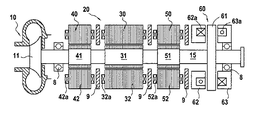
図2は、冷暖房空調(HVAC)のための遠心式電動コンプレッサの実施例を示しており、この遠心式電動コンプレッサは、ハイブリッド電気車輌(HEV)もしくは電気車輌(EV)あるいは航空機または他の種類の車輌に対して利用される。上記遠心式電動コンプレッサは、ターボチャージャを強化するために適用されてもよい。 FIG. 2 shows an embodiment of a centrifugal electric compressor for air conditioning and air conditioning (HVAC), which is a hybrid electric vehicle (HEV) or electric vehicle (EV) or an aircraft or other kind of Used for vehicles. The centrifugal electric compressor may be applied to strengthen the turbocharger.
モータ部分20のロータシャフト15は、遠心式コンプレッサホイール11を駆動するために、コンプレッサ部分10の遠心式コンプレッサホイール11に連結されている。
The
電気モータ30は、ロータ31を備えており、ロータ31は、誘導ロータ、永久磁石ロータ、ヒステリシスロータ及びリラクタンスロータのうちから選択される任意の種類からなる。電気モータ30は、巻線部32aを有したステータ32をさらに備えている。
The
第1能動型径方向磁気ベアリング及び第2能動型径方向磁気ベアリング40,50が、電気モータ30の両側に設置され、これにより、電動コンプレッサの機能動作中にシャフト15を浮揚した状態で支持する。各能動型径方向磁気ベアリング40,50は、シャフト15にしっかりと固定されたロータ41,51と、巻線部42a,52aを有したステータ42,52とを備えている。
The first active radial magnetic bearing and the second active radial magnetic bearing 40, 50 are installed on both sides of the
図2に示すように、能動型軸方向磁気ベアリング60(スラストベアリング)が、一方ではシャフト15の軸に対して垂直に取り付けられ且つロータ電機子を構成するディスク61と、他方では第1ステータ及び第2ステータ62,63であって、それぞれが、C字状のコアを有したステータ62,63に設置された少なくとも1つの環状コイルまたは巻線部62a,63aを有した、第1ステータ及び第2ステータ62,63と、を備えている。あるいは、各ステータ62,63は、2つのコイルを有するE字状のコアを有してもよい。
As shown in FIG. 2, an active axial magnetic bearing 60 (thrust bearing) is mounted on the one hand perpendicular to the axis of the
径方向ベアリングロータ41,51は、ステータ42,52の電磁石によって作り出された磁界によって適切な位置に保持された強磁性積層体を備えている。
The
シャフト15は、径方向磁気ベアリングにより接触せずに浮揚している。シャフトの位置は、例えば可変誘導型からなるセンサ(図示せず)によってモニターされている。センサは、所定位置からの如何なるずれも検出して制御システム(図2には示していない)で使用される信号を出し、これにより、シャフト15をその所定位置に戻すように導くために径方向ベアリングの巻線部42a,52aに電流を流すことを命令する。軸方向ベアリング60は、同じ原理に基づいており、センサ(図示せず)は、制御装置へ信号を送り、軸方向ベアリング60のコイル62a,63aにおける電流の命令を調整してシャフト15の軸方向位置を調整する。
The
補助接地ベアリング8が、基本的にはモータ部分20の開始動作または停止動作中に、ただし通常、車輌に存在する高レベルの振動に起因する衝突荷重が生じる短時間の断続的な期間中にも、シャフト15を支持するために使用されている。
The auxiliary ground bearing 8 is basically during the start or stop operation of the
一般的に言えば、回転シャフトの位置を検出するためのセンサに基づいてサーボ制御された能動型磁気サスペンションにより回転シャフトが一時停止する場合に、非常用ベアリングとして公知の補助ベアリングが設けられ、これにより、機械が停止している間、または磁気サスペンションの完全なもしくは部分的な故障の場合にシャフトを支持する。これにより、ステータの電磁石の巻線部が適切に電力を供給されないときに、ロータの磁気回路と、磁気ベアリングのステータまたはベアリングレスモータとが直接接触することを防止し、従って、その積層体の損傷を防ぐ。通常動作時には、補助ベアリングは、回転シャフトの周囲にクリアランスを残し、それ自体回転しない。補助ベアリングのために設けられるクリアランスは、通常、磁気ベアリングまたはベアリングレスモータにおける空隙の幅の約半分である。 Generally speaking, an auxiliary bearing known as an emergency bearing is provided when the rotating shaft is temporarily stopped by an active magnetic suspension servo-controlled based on a sensor for detecting the position of the rotating shaft. To support the shaft while the machine is stopped or in the event of a complete or partial failure of the magnetic suspension. This prevents direct contact between the rotor's magnetic circuit and the magnetic bearing's stator or bearingless motor when the stator electromagnet windings are not properly powered, and thus the stack's Prevent damage. During normal operation, the auxiliary bearing leaves a clearance around the rotating shaft and does not rotate itself. The clearance provided for the auxiliary bearing is typically about half the width of the air gap in a magnetic bearing or a bearingless motor.
補助接地/タッチダウンベアリング8は、さまざまな構成を有してもよく、例えば転がりベアリング、針状ベアリング、滑りベアリング、ブッシングなどであってもよい。
The auxiliary ground /
セパレータ9が、磁気ベアリング40,50,60及び電気モータ30のステータの巻線部間に設置されている。
A
ケーシングまたはフランジ及び冷媒を有する冷却システムは、従来型であり、図面には示さない。 The cooling system with casing or flange and refrigerant is conventional and is not shown in the drawing.
図2において、軸方向ベアリング60は、ディスク電機子61及びシャフト15の一端に設置された2つのステータ62,63を備えており、コンプレッサホイールは、シャフトの他端に設置されている。しかしながら、図1に示すように、軸方向ベアリング60は、コンプレッサホイール11と同じ側に設置されてもよい。
In FIG. 2, the
図1に示すように、電気モータ30及び径方向電磁式ベアリング40,50,60に結合され、可変周波数駆動部71及び増幅器72を備えた制御回路70が、フランジに統合され、且つ鉄シャフト15の第2端に設置されている。制御回路70は、フィードスルー74を介して、電気モータ30と、径方向電磁式ベアリング及び軸方向電磁式ベアリングと、に接続されている。コネクタ73が、制御回路70を電動コンプレッサから離れて設置されたさらなる制御装置へ接続させる働きをする。
As shown in FIG. 1, a
図3は、図2の実施形態と同様の実施形態を示している。ただし、軸方向磁気ベアリングは、シャフト15の端部双方に設置された2つの部分60A,60Bに分けられている。シャフト15と一体化されたディスク電機子61Aが、コンプレッサホイール11に近いシャフト15の第1端に設置され、且つ図1のステータ62と同様である第1コイル62aを有した第1ステータ62と協働する。シャフト15と一体化されたディスク電機子61Bが、シャフト15の第2端に設置され、且つ図1のステータ63と同様である第2コイル63aを有した第2ステータ63と協働する。
FIG. 3 shows an embodiment similar to the embodiment of FIG. However, the axial magnetic bearing is divided into two
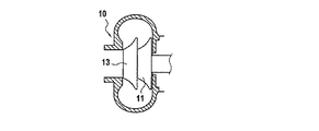
図1から図3は、単一のホイールを有したコンプレッサ部分10を示している。しかしながら、コンプレッサ部分10の他の構成は、本明細書に開示される異なる実施形態と組み合わせて用いられてもよい。
1 to 3 show a
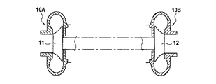
従って図7に示すように、コンプレッサ部分10は、二重ホイール11,13を含んでもよい。図8に示すように、コンプレッサ部分10A,10Bは、直列型のホイール11,12を含んでもよい。図9に示すように、コンプレッサ部分10A,10Bは、二重直列型のホイール11,13,12,14を含んでもよい。図7から図9によるコンプレッサホイールの構造は、圧縮比を増大させるか、流量を増大させるものである。
Accordingly, as shown in FIG. 7, the
以下、本発明の好ましい実施形態を、図4から図6を参照して説明する。 Hereinafter, a preferred embodiment of the present invention will be described with reference to FIGS.
図4は、電気モータ30及び軸方向ベアリング60もしくは60A,60Bが単一の軸方向ベアリングレスモータ130によって置換されたので、図1から図3の実施形態よりもよりコンパクトである鉄シャフト15及びモータ部分20を有する実施形態を示している。図4では、コンプレッサ部分10は省略されているが、図1から図3及び図7から図9を参照して上述したものとして実現される。
FIG. 4 shows the
図4の実施形態は、シャフト長の減少を可能にし、従って全体的な配置を改善する。 The embodiment of FIG. 4 allows a reduction in shaft length and thus improves the overall arrangement.
軸方向ベアリングレスモータ130は、シャフト15と一体化されたディスク状の中央電機子131と、巻線部132a,133aを有した第1ステータ132及び第2ステータ133と、を備えている。
The
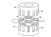
図5は、軸方向ベアリングレスモータ130の考えられる構造の実施例を斜視図で示している。図5における軸方向ベアリングレスモータ130は、複数の極の対を持つ電機子138を有したロータ部分131と、第1ステータ部分及び第2ステータ部分132,133と、を備えている。各第1ステータ部分及び第2ステータ部分132,133は、モータトルク及び軸方向の支持力を与えるように構成された巻線部(図5には示していない)を受けるためにスロット134,135をそれぞれ有したコアを備え、第1ステータ部分及び第2ステータ部分132,133は、ロータ部分131の両側に設置されている。
FIG. 5 shows a perspective view of an example of a possible structure of the
コイルから独立した軸方向ベアリングレスモータのステータ部分132,133は、支持力及びモータトルクを与えるために使用される。
The
あるいは、必要とされる支持力及びモータトルクが、組み合わせられた巻線部によって各コイルで発生されてもよい。このような場合には、必要とされるモータのアンペア回数及び支持のアンペア回数が単一のコイルによってもたらされる。 Alternatively, the required support force and motor torque may be generated at each coil by a combined winding section. In such cases, a single coil provides the required motor amperage and support amperage.
複数の極の対を持つ電機子138は、例のために図5に示される。しかしながら、ロータ131は、選択された原理(永久磁石式、誘導式、スイッチトリラクタンス式、ヒステリシス式)に応じて異なる構造的部材を有してもよい。
An
限定されない例として、ステータ132及び永久磁石138を有するロータ131は、永久磁石モータを構成し、ロータの表面上の永久磁石138は、第1方向(図5の構造における上向きの方向)の軸方向力を生み出し、ステータ133及びロータ131は、同期リラクタンスモータを構成し、同期リラクタンスモータの巻線部の電流は、第1方向に対する反対方向(図5の構造における下向きの方向)への調節可能な軸方向力を生み出す。従って、ロータの軸方向位置は、同期型モータの電流によって制御することができる。しかしながら、上述したように、軸方向ベアリングレスモータ130がモータトルク及び軸方向支持力を与える2つの機能を達成するのであれば、他の種類のモータの組み合わせが選択されてもよい。
As a non-limiting example, the
上述した能動型径方向磁気ベアリング40及び50と同様であり且つロータ電機子141,151及び巻線部142a,152aを有したステータ142,152を備えた能動型径方向磁気ベアリング140及び150は、軸方向ベアリングレスモータ130の両側に設置されている。
Active radial
しかしながら、別の実施形態によれば、各能動型径方向磁気ベアリング140,150は、径方向ベアリングレスモータ180によって置換されてもよい。
However, according to another embodiment, each active radial
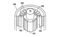
径方向ベアリングレスモータ180の実施例は、図6に示されている。このような径方向ベアリングレスモータ180は、シャフト15と一体化されたロータ181と、コイル185を受けるためのスロット184を有したステータ182と、を備えている。ロータ181は、選択された原理(永久磁石式、誘導式、スイッチトリラクタンス式、ヒステリシス式)に応じて異なる構造的部材183を有している。
An embodiment of a
基本的には、ステータの巻線部185は、トルク用巻線部及び停止力用巻線部の機能双方を達成する。実施例として、一組の異なる極を有する2つの巻線部のセットによって作り出される2つの磁界が重ね合わせられると、トルク及び径方向力が生じる。従って、例えばリラクタンスモータの4極のモータ巻線部を2極のベアリング巻線部と組み合わせることが可能であるが、多くの他の実施形態が考えられる。 Basically, the stator winding 185 achieves both functions of the torque winding and the stopping force winding. As an example, torque and radial force are generated when two magnetic fields created by a set of two winding sections having a set of different poles are superimposed. Thus, for example, a 4-pole motor winding of a reluctance motor can be combined with a 2-pole bearing winding, but many other embodiments are possible.
特許文献2は、ベアリングレススイッチトリラクタンスモータの例を開示している。 Patent Document 2 discloses an example of a bearingless switched reluctance motor.
好ましい実施形態が示され且つ説明されたが、任意の変更及び改良が、添付の特許請求の範囲に規定されるように本発明の範囲から逸脱することなく本開示の中でなされてもよいことを理解するべきである。 While preferred embodiments have been shown and described, any changes and modifications may be made in the present disclosure without departing from the scope of the invention as defined in the appended claims. Should be understood.
図4において、参照符号130は、シャフト15を支持するために2つの径方向電磁式手段140,150間に設置された軸方向ベアリングレスモータを示している。径方向電磁式手段140,150が、例えば図6に開示された第1径方向ベアリングレスモータ及び第2径方向ベアリングレスモータ180を備え、軸方向能動型磁気ベアリング、例えば図2に示されたスラストベアリング60が軸方向ベアリングレスモータ130に対して置換されてもよい。
In FIG. 4,
8 補助接地ベアリング、9 セパレータ、10 遠心式コンプレッサ部分、11 ホイール、12 ホイール、13 ホイール、14 ホイール、15 シャフト、20 モータ部分、30 電気モータ、40 第1能動型径方向磁気ベアリング、50 第2能動型径方向磁気ベアリング、60 能動型軸方向磁気ベアリング、70 制御回路、74 フィードスルー、130 軸方向ベアリングレスモータ、131 ロータ部分、132 第1ステータ部分、133 第2ステータ部分、134 スロット、135 スロット、138 電機子、140 第1能動型径方向磁気ベアリング、150 第2能動型径方向磁気ベアリング、180 径方向ベアリングレスモータ 8 auxiliary ground bearing, 9 separator, 10 centrifugal compressor part, 11 wheel, 12 wheel, 13 wheel, 14 wheel, 15 shaft, 20 motor part, 30 electric motor, 40 first active radial magnetic bearing, 50 second Active radial magnetic bearing, 60 active axial magnetic bearing, 70 control circuit, 74 feedthrough, 130 axial bearingless motor, 131 rotor part, 132 first stator part, 133 second stator part, 134 slot, 135 Slot, 138 armature, 140 first active radial magnetic bearing, 150 second active radial magnetic bearing, 180 radial bearingless motor
Claims (15)
該電動コンプレッサが、モータ部分(20)と、シャフト(15)を通じて前記モータ部分(20)によって駆動される遠心式コンプレッサ部分(10)とを備え、
該電動コンプレッサの機能動作中に前記シャフト(15)を浮揚させるための電磁式手段と、補助接地ベアリング(8)とをさらに備えていることを特徴とする電動コンプレッサ。 An electric compressor for an air conditioning system for a vehicle,
The electric compressor comprises a motor part (20) and a centrifugal compressor part (10) driven by the motor part (20) through a shaft (15),
An electric compressor characterized by further comprising electromagnetic means for levitating the shaft (15) during the functional operation of the electric compressor and an auxiliary ground bearing (8).
前記軸方向ベアリングレスモータ(130)及び前記径方向電磁式手段と結合された制御回路(70)が、前記シャフト(15)の第2端に設置され、且つフィードスルー(74)を介して前記軸方向ベアリングレスモータ(130)及び前記径方向電磁式手段に接続されていることを特徴とする請求項2に記載の電動コンプレッサ。 The centrifugal compressor part (10) comprises a wheel (11) at the first end of the shaft (15),
A control circuit (70) coupled to the axial bearingless motor (130) and the radial electromagnetic means is installed at a second end of the shaft (15) and is fed via a feedthrough (74). Electric compressor according to claim 2, characterized in that it is connected to an axial bearingless motor (130) and to the radial electromagnetic means.
能動型軸方向磁気ベアリング(60)は、前記遠心式コンプレッサ部分(10)の近傍に設置され、
前記電気モータ(30)と、前記能動型軸方向磁気ベアリング(60)と、前記第1能動型径方向磁気ベアリング及び前記第2能動型径方向磁気ベアリング(40,50)と、に結合された制御回路(70)は、前記シャフト(15)の第2端に設置され、且つフィードスルー(74)を介して前記電気モータ(30)と、前記能動型軸方向磁気ベアリング(60)と、前記第1能動型径方向磁気ベアリング及び前記第2能動型径方向磁気ベアリング(40,50)と、に接続されていることを特徴とする請求項14に記載の電動コンプレッサ。 The centrifugal compressor part (10) comprises at least one wheel (11) at the first end of the shaft (15),
An active axial magnetic bearing (60) is installed in the vicinity of the centrifugal compressor part (10),
Coupled to the electric motor (30), the active axial magnetic bearing (60), the first active radial magnetic bearing and the second active radial magnetic bearing (40, 50). A control circuit (70) is installed at the second end of the shaft (15) and via the feedthrough (74) the electric motor (30), the active axial magnetic bearing (60), and the 15. The electric compressor according to claim 14, wherein the electric compressor is connected to a first active radial magnetic bearing and the second active radial magnetic bearing (40, 50).
Applications Claiming Priority (2)
| Application Number | Priority Date | Filing Date | Title |
|---|---|---|---|
| EP12305730.9 | 2012-06-22 | ||
| EP12305730.9A EP2677177B1 (en) | 2012-06-22 | 2012-06-22 | Electric centrifugal compressor for vehicles |
Publications (2)
| Publication Number | Publication Date |
|---|---|
| JP2014005833A true JP2014005833A (en) | 2014-01-16 |
| JP6193007B2 JP6193007B2 (en) | 2017-09-06 |
Family
ID=46717795
Family Applications (1)
| Application Number | Title | Priority Date | Filing Date |
|---|---|---|---|
| JP2013130344A Active JP6193007B2 (en) | 2012-06-22 | 2013-06-21 | Centrifugal electric compressor for vehicles |
Country Status (5)
| Country | Link |
|---|---|
| US (2) | US20130343927A1 (en) |
| EP (1) | EP2677177B1 (en) |
| JP (1) | JP6193007B2 (en) |
| CN (1) | CN103821735A (en) |
| CA (1) | CA2820449A1 (en) |
Cited By (4)
| Publication number | Priority date | Publication date | Assignee | Title |
|---|---|---|---|---|
| JP2016173084A (en) * | 2015-03-18 | 2016-09-29 | 株式会社日立製作所 | Downhole compressor |
| CN107810330A (en) * | 2015-06-29 | 2018-03-16 | 大金应用美国股份有限公司 | The method that refrigeration is produced using R1233zd |
| WO2018207767A1 (en) * | 2017-05-09 | 2018-11-15 | ダイキン工業株式会社 | Turbo compressor |
| WO2018207669A1 (en) * | 2017-05-09 | 2018-11-15 | ダイキン工業株式会社 | Electric motor system and turbo compressor provided therewith |
Families Citing this family (23)
| Publication number | Priority date | Publication date | Assignee | Title |
|---|---|---|---|---|
| JP6090926B2 (en) * | 2013-05-30 | 2017-03-08 | 三菱重工業株式会社 | Turbo compressor and turbo refrigerator using the same |
| JP5924315B2 (en) * | 2013-08-08 | 2016-05-25 | トヨタ自動車株式会社 | Vehicle control device |
| CN105257698B (en) * | 2014-07-14 | 2018-01-19 | 张玉宝 | A kind of single-degree-of-freedom magnetic suspension rotor support system and magnetic centering bearing |
| CN104154028B (en) * | 2014-08-06 | 2016-06-29 | 南京磁谷科技有限公司 | A kind of blower fan that can reduce rotor axial power |
| DE102015207341B4 (en) * | 2015-04-22 | 2019-02-14 | Ford Global Technologies, Llc | Compressor and motor vehicle |
| US10177627B2 (en) | 2015-08-06 | 2019-01-08 | Massachusetts Institute Of Technology | Homopolar, flux-biased hysteresis bearingless motor |
| CN105465175B (en) * | 2015-12-28 | 2018-03-09 | 宁波达奋精工轴承有限公司 | A kind of active magnetic bearing |
| CN105508425B (en) * | 2015-12-28 | 2018-03-09 | 宁波达奋精工轴承有限公司 | A kind of self-power generation type magnetic bearing |
| CN105422623B (en) * | 2015-12-28 | 2018-03-09 | 宁波达奋精工轴承有限公司 | Self-power generation type magnetic bearing |
| US20170260987A1 (en) * | 2016-03-11 | 2017-09-14 | Daikin Applied Americas Inc. | Centrifugal compressor with casing treatment bypass |
| JP6672056B2 (en) * | 2016-04-22 | 2020-03-25 | 三菱重工サーマルシステムズ株式会社 | Turbo compressor, turbo refrigeration device provided with the same |
| KR101835338B1 (en) * | 2016-08-30 | 2018-03-07 | 엘지전자 주식회사 | Compressor and Chiller system including it |
| CN114876825A (en) * | 2017-03-24 | 2022-08-09 | 江森自控泰科知识产权控股有限责任合伙公司 | Magnetic bearing motor compressor |
| WO2019125718A1 (en) | 2017-12-22 | 2019-06-27 | Massachusetts Institute Of Technology | Homopolar bearingless slice motors |
| CN110247496A (en) * | 2018-03-07 | 2019-09-17 | 台达电子工业股份有限公司 | Mechanical device and its bearingless motors |
| JP2019210899A (en) * | 2018-06-07 | 2019-12-12 | 株式会社豊田自動織機 | Centrifugal compressor |
| JP6887404B2 (en) * | 2018-07-13 | 2021-06-16 | ミネベアミツミ株式会社 | motor |
| US10955000B2 (en) * | 2018-11-09 | 2021-03-23 | Bernabe Segura Candelaria | Bearingless hub assembly with electromagnetic drive system and associated methods |
| DE102018129854A1 (en) * | 2018-11-27 | 2020-05-28 | Voith Patent Gmbh | Turbocompressor |
| CN110545010A (en) * | 2019-01-20 | 2019-12-06 | 深圳市实能高科动力有限公司 | bearingless motor and railway wagon carriage provided with same |
| JP2020128745A (en) * | 2019-02-01 | 2020-08-27 | ホワイト ナイト フルイド ハンドリング インコーポレーテッドWhite Knight Fluid Handling Inc. | Pump having magnet for journaling and magnetically axially positioning rotor thereof, and related method |
| CN111828336A (en) * | 2019-04-15 | 2020-10-27 | 孟想 | Ultra-silent zero-leakage nuclear main pump/fan compressor integrated design scheme |
| JP6978703B2 (en) * | 2020-03-31 | 2021-12-08 | ダイキン工業株式会社 | Centrifugal compressor |
Citations (6)
| Publication number | Priority date | Publication date | Assignee | Title |
|---|---|---|---|---|
| JPS5968595A (en) * | 1982-06-04 | 1984-04-18 | クル−ゾ−・ロワ−ル | Integral type centrifugal motor compressor |
| US5857348A (en) * | 1993-06-15 | 1999-01-12 | Multistack International Limited | Compressor |
| JP2002325490A (en) * | 2001-04-25 | 2002-11-08 | Sankyo Seiki Mfg Co Ltd | Magnetic levitation motor |
| JP2004535531A (en) * | 2000-11-17 | 2004-11-25 | ソシエテ・ドゥ・メカニーク・マグネティーク | Rotary machine with magnetic axial abutment including current source |
| JP2005519214A (en) * | 2002-02-28 | 2005-06-30 | ターボコー インク. | Centrifugal compressor |
| JP2006152994A (en) * | 2004-12-01 | 2006-06-15 | Mitsubishi Heavy Ind Ltd | Centrifugal compressor |
Family Cites Families (8)
| Publication number | Priority date | Publication date | Assignee | Title |
|---|---|---|---|---|
| JP2689834B2 (en) * | 1992-12-11 | 1997-12-10 | 株式会社日立製作所 | Motors, mirror motors and laser beam printers |
| JP3969840B2 (en) | 1998-05-25 | 2007-09-05 | 株式会社日本自動車部品総合研究所 | Electric compressor |
| DE50306042D1 (en) * | 2002-05-16 | 2007-02-01 | Silphenix Gmbh | PASSIVE, DYNAMICALLY STABILIZING MAGNETIC BEARING AND DRIVE |
| US6727618B1 (en) | 2002-06-10 | 2004-04-27 | The United States Of America, As Represented By The Administrator Of National Aeronautics And Space Administration | Bearingless switched reluctance motor |
| CN1173138C (en) * | 2002-07-15 | 2004-10-27 | 西安交通大学 | Electromagnetic suspending air expanding absorption type refrigeration method and its refrigerating air conditioner set |
| US20080218008A1 (en) * | 2007-03-08 | 2008-09-11 | General Electric Company | Rotor and Stator Assemblies that Utilize Magnetic Bearings for Use in Corrosive Environments |
| CN100491740C (en) * | 2007-08-31 | 2009-05-27 | 清华大学 | High temperature gas cooled reactor centrifugal type helium gas compressor of pebble bed |
| DE102008031994B4 (en) * | 2008-04-29 | 2011-07-07 | Siemens Aktiengesellschaft, 80333 | Fluid energy machine |
-
2012
- 2012-06-22 EP EP12305730.9A patent/EP2677177B1/en active Active
-
2013
- 2013-06-20 CA CA2820449A patent/CA2820449A1/en not_active Abandoned
- 2013-06-21 JP JP2013130344A patent/JP6193007B2/en active Active
- 2013-06-24 CN CN201310251840.0A patent/CN103821735A/en active Pending
- 2013-06-24 US US13/925,390 patent/US20130343927A1/en not_active Abandoned
- 2013-06-24 US US13/925,657 patent/US20140023534A1/en not_active Abandoned
Patent Citations (6)
| Publication number | Priority date | Publication date | Assignee | Title |
|---|---|---|---|---|
| JPS5968595A (en) * | 1982-06-04 | 1984-04-18 | クル−ゾ−・ロワ−ル | Integral type centrifugal motor compressor |
| US5857348A (en) * | 1993-06-15 | 1999-01-12 | Multistack International Limited | Compressor |
| JP2004535531A (en) * | 2000-11-17 | 2004-11-25 | ソシエテ・ドゥ・メカニーク・マグネティーク | Rotary machine with magnetic axial abutment including current source |
| JP2002325490A (en) * | 2001-04-25 | 2002-11-08 | Sankyo Seiki Mfg Co Ltd | Magnetic levitation motor |
| JP2005519214A (en) * | 2002-02-28 | 2005-06-30 | ターボコー インク. | Centrifugal compressor |
| JP2006152994A (en) * | 2004-12-01 | 2006-06-15 | Mitsubishi Heavy Ind Ltd | Centrifugal compressor |
Cited By (9)
| Publication number | Priority date | Publication date | Assignee | Title |
|---|---|---|---|---|
| JP2016173084A (en) * | 2015-03-18 | 2016-09-29 | 株式会社日立製作所 | Downhole compressor |
| CN107810330A (en) * | 2015-06-29 | 2018-03-16 | 大金应用美国股份有限公司 | The method that refrigeration is produced using R1233zd |
| JP2018521291A (en) * | 2015-06-29 | 2018-08-02 | ダイキン アプライド アメリカズ インコーポレィティッド | Method for providing cooling using R1233zd |
| US10247448B2 (en) | 2015-06-29 | 2019-04-02 | Daikin Applied Americas Inc. | Method of producing refrigeration with R1233zd |
| WO2018207767A1 (en) * | 2017-05-09 | 2018-11-15 | ダイキン工業株式会社 | Turbo compressor |
| WO2018207669A1 (en) * | 2017-05-09 | 2018-11-15 | ダイキン工業株式会社 | Electric motor system and turbo compressor provided therewith |
| JP2018191455A (en) * | 2017-05-09 | 2018-11-29 | ダイキン工業株式会社 | Motor system and turbo compressor with the same |
| JP2018189358A (en) * | 2017-05-09 | 2018-11-29 | ダイキン工業株式会社 | Turbo-compressor |
| US11300131B2 (en) | 2017-05-09 | 2022-04-12 | Daikin Industries, Ltd. | Electric motor system and turbo compressor provided therewith |
Also Published As
| Publication number | Publication date |
|---|---|
| JP6193007B2 (en) | 2017-09-06 |
| EP2677177B1 (en) | 2020-10-14 |
| US20130343927A1 (en) | 2013-12-26 |
| US20140023534A1 (en) | 2014-01-23 |
| EP2677177A1 (en) | 2013-12-25 |
| CN103821735A (en) | 2014-05-28 |
| CA2820449A1 (en) | 2013-12-22 |
Similar Documents
| Publication | Publication Date | Title |
|---|---|---|
| JP6193007B2 (en) | Centrifugal electric compressor for vehicles | |
| CA2820446C (en) | Electric centrifugal compressor for vehicles | |
| US9863431B2 (en) | Hybrid magnetic suspension of a rotor | |
| JP4274423B2 (en) | Electric motor integrated in vehicle wheel | |
| US6927517B2 (en) | Rotary machine with axial stop incorporating a current generator | |
| US11300131B2 (en) | Electric motor system and turbo compressor provided therewith | |
| EP2784326B1 (en) | Compact turbomachine with magnetic bearings and auxiliary bearings | |
| US20100123364A1 (en) | Substantially parallel flux uncluttered rotor machines | |
| CN110249145B (en) | Thrust active magnetic bearing for shaft slow rolling control | |
| US20140265689A1 (en) | Generating radial electromagnetic forces | |
| CN113853724A (en) | Four-pole synchronous reluctance motor | |
| US11005349B2 (en) | Electric motor system, and turbo compressor provided with same | |
| JP2001190045A (en) | Magnetically levitated motor | |
| JP5298476B2 (en) | Induction synchronous motor | |
| RU2540696C1 (en) | High-rate electrical machine with vertical shaft | |
| Jaatinen et al. | Comparison of winding arrangements of a high-speed interior permanent magnet bearingless machine | |
| CN112088487B (en) | Motor system and turbo compressor including the same | |
| JP2021090256A (en) | Electric motor system and turbo compressor having the same | |
| WO2022202543A1 (en) | Electric motor system, turbo compressor, and refrigeration device | |
| CN216929758U (en) | Axial magnetic bearing structure of motor and magnetic suspension high-speed motor | |
| US20240003357A1 (en) | Centrifugal compressor for refrigeration system and refrigeration system |
Legal Events
| Date | Code | Title | Description |
|---|---|---|---|
| A621 | Written request for application examination |
Free format text: JAPANESE INTERMEDIATE CODE: A621 Effective date: 20160518 |
|
| A977 | Report on retrieval |
Free format text: JAPANESE INTERMEDIATE CODE: A971007 Effective date: 20170310 |
|
| A131 | Notification of reasons for refusal |
Free format text: JAPANESE INTERMEDIATE CODE: A131 Effective date: 20170317 |
|
| A521 | Request for written amendment filed |
Free format text: JAPANESE INTERMEDIATE CODE: A523 Effective date: 20170605 |
|
| TRDD | Decision of grant or rejection written | ||
| A01 | Written decision to grant a patent or to grant a registration (utility model) |
Free format text: JAPANESE INTERMEDIATE CODE: A01 Effective date: 20170710 |
|
| A61 | First payment of annual fees (during grant procedure) |
Free format text: JAPANESE INTERMEDIATE CODE: A61 Effective date: 20170809 |
|
| R150 | Certificate of patent or registration of utility model |
Ref document number: 6193007 Country of ref document: JP Free format text: JAPANESE INTERMEDIATE CODE: R150 |
|
| R250 | Receipt of annual fees |
Free format text: JAPANESE INTERMEDIATE CODE: R250 |
|
| R250 | Receipt of annual fees |
Free format text: JAPANESE INTERMEDIATE CODE: R250 |
|
| R250 | Receipt of annual fees |
Free format text: JAPANESE INTERMEDIATE CODE: R250 |
|
| R250 | Receipt of annual fees |
Free format text: JAPANESE INTERMEDIATE CODE: R250 |