JP2014003559A - Radiation image pick-up device and radiation image pick-up system - Google Patents
Radiation image pick-up device and radiation image pick-up system Download PDFInfo
- Publication number
- JP2014003559A JP2014003559A JP2012139267A JP2012139267A JP2014003559A JP 2014003559 A JP2014003559 A JP 2014003559A JP 2012139267 A JP2012139267 A JP 2012139267A JP 2012139267 A JP2012139267 A JP 2012139267A JP 2014003559 A JP2014003559 A JP 2014003559A
- Authority
- JP
- Japan
- Prior art keywords
- radiation
- read
- value
- leak data
- dleak
- Prior art date
- Legal status (The legal status is an assumption and is not a legal conclusion. Google has not performed a legal analysis and makes no representation as to the accuracy of the status listed.)
- Pending
Links
- 230000005855 radiation Effects 0.000 title claims abstract description 491
- 238000001514 detection method Methods 0.000 claims abstract description 263
- 238000000034 method Methods 0.000 claims abstract description 213
- 230000008569 process Effects 0.000 claims abstract description 206
- 238000003384 imaging method Methods 0.000 claims description 112
- 238000012545 processing Methods 0.000 claims description 59
- 238000004891 communication Methods 0.000 claims description 8
- 230000007547 defect Effects 0.000 abstract description 38
- 239000000758 substrate Substances 0.000 description 21
- 238000009825 accumulation Methods 0.000 description 20
- 230000003068 static effect Effects 0.000 description 16
- 230000005611 electricity Effects 0.000 description 15
- 101150108167 TAC1 gene Proteins 0.000 description 12
- 238000012423 maintenance Methods 0.000 description 9
- 230000000875 corresponding effect Effects 0.000 description 8
- 101150100415 Tac3 gene Proteins 0.000 description 6
- 230000002596 correlated effect Effects 0.000 description 6
- 238000010586 diagram Methods 0.000 description 6
- 230000004048 modification Effects 0.000 description 6
- 238000012986 modification Methods 0.000 description 6
- 238000005070 sampling Methods 0.000 description 6
- 230000006870 function Effects 0.000 description 5
- 230000003902 lesion Effects 0.000 description 5
- 239000003990 capacitor Substances 0.000 description 4
- 238000012937 correction Methods 0.000 description 4
- 239000010408 film Substances 0.000 description 4
- 230000001678 irradiating effect Effects 0.000 description 4
- 230000002411 adverse Effects 0.000 description 3
- 238000006243 chemical reaction Methods 0.000 description 3
- 230000000694 effects Effects 0.000 description 3
- 238000003702 image correction Methods 0.000 description 3
- 230000002829 reductive effect Effects 0.000 description 3
- 230000007704 transition Effects 0.000 description 3
- 230000003321 amplification Effects 0.000 description 2
- 230000008859 change Effects 0.000 description 2
- 230000001276 controlling effect Effects 0.000 description 2
- 230000007423 decrease Effects 0.000 description 2
- 230000006866 deterioration Effects 0.000 description 2
- 239000000463 material Substances 0.000 description 2
- 239000011159 matrix material Substances 0.000 description 2
- 239000000203 mixture Substances 0.000 description 2
- 238000003199 nucleic acid amplification method Methods 0.000 description 2
- 230000004044 response Effects 0.000 description 2
- 230000002441 reversible effect Effects 0.000 description 2
- 241000531891 Alburnus alburnus Species 0.000 description 1
- 230000009471 action Effects 0.000 description 1
- 239000000853 adhesive Substances 0.000 description 1
- 230000001070 adhesive effect Effects 0.000 description 1
- 239000002313 adhesive film Substances 0.000 description 1
- 230000009286 beneficial effect Effects 0.000 description 1
- 230000005540 biological transmission Effects 0.000 description 1
- 230000003247 decreasing effect Effects 0.000 description 1
- 230000002950 deficient Effects 0.000 description 1
- 230000005284 excitation Effects 0.000 description 1
- 239000011521 glass Substances 0.000 description 1
- 239000004973 liquid crystal related substance Substances 0.000 description 1
- 238000011160 research Methods 0.000 description 1
- 230000035945 sensitivity Effects 0.000 description 1
- 238000003530 single readout Methods 0.000 description 1
- 230000001360 synchronised effect Effects 0.000 description 1
- 239000010409 thin film Substances 0.000 description 1
Images


Classifications
-
- G—PHYSICS
- G01—MEASURING; TESTING
- G01T—MEASUREMENT OF NUCLEAR OR X-RADIATION
- G01T1/00—Measuring X-radiation, gamma radiation, corpuscular radiation, or cosmic radiation
- G01T1/16—Measuring radiation intensity
- G01T1/17—Circuit arrangements not adapted to a particular type of detector
-
- H—ELECTRICITY
- H04—ELECTRIC COMMUNICATION TECHNIQUE
- H04N—PICTORIAL COMMUNICATION, e.g. TELEVISION
- H04N5/00—Details of television systems
- H04N5/30—Transforming light or analogous information into electric information
- H04N5/32—Transforming X-rays
-
- G—PHYSICS
- G01—MEASURING; TESTING
- G01T—MEASUREMENT OF NUCLEAR OR X-RADIATION
- G01T1/00—Measuring X-radiation, gamma radiation, corpuscular radiation, or cosmic radiation
- G01T1/16—Measuring radiation intensity
- G01T1/24—Measuring radiation intensity with semiconductor detectors
- G01T1/247—Detector read-out circuitry
-
- H—ELECTRICITY
- H04—ELECTRIC COMMUNICATION TECHNIQUE
- H04N—PICTORIAL COMMUNICATION, e.g. TELEVISION
- H04N25/00—Circuitry of solid-state image sensors [SSIS]; Control thereof
- H04N25/60—Noise processing, e.g. detecting, correcting, reducing or removing noise
- H04N25/63—Noise processing, e.g. detecting, correcting, reducing or removing noise applied to dark current
-
- H—ELECTRICITY
- H05—ELECTRIC TECHNIQUES NOT OTHERWISE PROVIDED FOR
- H05G—X-RAY TECHNIQUE
- H05G1/00—X-ray apparatus involving X-ray tubes; Circuits therefor
- H05G1/08—Electrical details
- H05G1/26—Measuring, controlling or protecting
- H05G1/28—Measuring or recording actual exposure time; Counting number of exposures; Measuring required exposure time
Abstract
Description
本発明は、放射線画像撮影装置および放射線画像撮影システムに係り、特に、放射線の照射開始を検出して放射線画像撮影を行う放射線画像撮影装置およびそれを用いた放射線画像撮影システムに関する。 The present invention relates to a radiographic image capturing apparatus and a radiographic image capturing system, and more particularly, to a radiographic image capturing apparatus that performs radiographic image capturing by detecting the start of radiation irradiation and a radiographic image capturing system using the same.
照射されたX線等の放射線の線量に応じて検出素子で電荷を発生させて電気信号に変換するいわゆる直接型の放射線画像撮影装置や、照射された放射線をシンチレーター等で可視光等の他の波長の光に変換した後、変換され照射された光のエネルギーに応じてフォトダイオード等の光電変換素子で電荷を発生させて電気信号(すなわち画像データ)に変換するいわゆる間接型の放射線画像撮影装置が種々開発されている。なお、本発明では、直接型の放射線画像撮影装置における検出素子や、間接型の放射線画像撮影装置における光電変換素子を、あわせて放射線検出素子という。 A so-called direct-type radiographic imaging device that generates electric charges by a detection element in accordance with the dose of irradiated radiation such as X-rays and converts it into an electrical signal, or other radiation such as visible light with a scintillator A so-called indirect radiographic imaging device that converts the light into a wavelength and then generates electric charges by a photoelectric conversion element such as a photodiode in accordance with the energy of the converted and irradiated light to convert it into an electrical signal (ie, image data). Have been developed. In the present invention, the detection element in the direct type radiographic imaging apparatus and the photoelectric conversion element in the indirect type radiographic imaging apparatus are collectively referred to as a radiation detection element.
このタイプの放射線画像撮影装置はFPD(Flat Panel Detector)として知られており、従来は支持台と一体的に形成された、いわゆる専用機型(固定型等ともいう。)として構成されていたが(例えば特許文献1参照)、近年、放射線検出素子等を筐体内に収納し、持ち運び可能とした可搬型の放射線画像撮影装置が開発され、実用化されている(例えば特許文献2、3参照)。
This type of radiographic image capturing apparatus is known as an FPD (Flat Panel Detector), and is conventionally configured as a so-called dedicated machine type (also referred to as a fixed type) integrally formed with a support base. (For example, refer to Patent Document 1) In recent years, a portable radiographic imaging apparatus in which a radiation detection element or the like is housed in a housing and can be carried has been developed and put into practical use (for example, refer to
このような放射線画像撮影装置では、例えば後述する図3等に示すように、通常、複数の放射線検出素子7が、検出部P上に二次元状(マトリクス状)に配列され、各放射線検出素子7にそれぞれ薄膜トランジスター(Thin Film Transistor。以下、TFTという。)等で形成されたスイッチ手段8が接続されて構成される。
In such a radiographic imaging apparatus, for example, as shown in FIG. 3 and the like, which will be described later, normally, a plurality of
そして、通常、放射線発生装置の放射線源から放射線画像撮影装置に対して、被撮影者の身体等すなわち被写体を介して放射線が照射されることで放射線画像撮影が行われる。そして、撮影後、ゲートドライバー15bから走査線5の各ラインL1〜Lxにオン電圧を順次印加して、各TFT8を順次オン状態として、放射線の照射により各放射線検出素子7内で発生して蓄積された電荷を各信号線6に順次放出させて、各読み出し回路17で画像データDとしてそれぞれ読み出すように構成される。
In general, radiographic imaging is performed by irradiating radiation from the radiation source of the radiation generating apparatus to the radiographic imaging apparatus through the body of the subject, that is, the subject. Then, after imaging, an ON voltage is sequentially applied from the
ところで、このような放射線画像撮影装置を用いた従来の放射線画像撮影システムでは、放射線画像撮影装置と放射線発生装置との間で信号のやり取りを行って放射線画像撮影を行っていた。しかし、例えば、放射線画像撮影装置と放射線発生装置の製造元が異なっているような場合には、両者の間でインターフェースを構築することが必ずしも容易でない場合があり、或いは、インターフェースを構築できない場合もある。 By the way, in the conventional radiographic imaging system using such a radiographic imaging apparatus, radiographic imaging was performed by exchanging signals between the radiographic imaging apparatus and the radiation generating apparatus. However, for example, when the manufacturers of the radiographic imaging apparatus and the radiation generation apparatus are different, it may not always be easy to construct an interface between them, or the interface may not be constructed. .
このような場合、放射線画像撮影装置側から見ると、放射線源からどのようなタイミングで放射線が照射されるかが分からない。そのため、このような場合には、放射線画像撮影装置が、放射線源から放射線が照射されたことを装置自体で検出できるように構成される必要がある。そして、このように放射線画像撮影装置自体で放射線の照射開始を検出して撮影を行うことが可能な放射線画像撮影装置が種々開発されている。 In such a case, when viewed from the side of the radiographic imaging device, it is not known at what timing the radiation is emitted from the radiation source. Therefore, in such a case, the radiographic imaging device needs to be configured so that the device itself can detect that radiation has been emitted from the radiation source. Various types of radiographic image capturing apparatuses that can detect the start of radiation irradiation and perform image capturing with the radiographic image capturing apparatus itself have been developed.
例えば、特許文献4や特許文献5に記載の発明では、放射線画像撮影装置に対する放射線の照射が開始されて各放射線検出素子7内に電荷が発生すると、各放射線検出素子7から、各放射線検出素子7に接続されているバイアス線9(後述する図3等参照)に電荷が流れ出してバイアス線9を流れる電流が増加することを利用して、バイアス線9に電流検出手段を設けてバイアス線9内を流れる電流の電流値を検出し、その電流値に基づいて放射線の照射の開始等を検出することが提案されている。
For example, in the inventions described in
しかし、上記のように構成すると、電流検出手段で発生するノイズが各放射線検出素子7内に蓄積される電荷量に悪影響を与え、各放射線検出素子7から読み出される画像データDに、除去することが必ずしも容易でないノイズが重畳される等の問題があることが分かってきた。
However, when configured as described above, noise generated by the current detection means adversely affects the amount of charge accumulated in each
そこで、本発明者らが、放射線画像撮影装置自体で放射線が照射されたことを検出する別の手法について種々研究を重ねた結果、放射線画像撮影装置自体で放射線が照射されたことを的確に検出することが可能な手法を見出すことができた(例えば特許文献6参照)。この新たな検出方法では、放射線画像撮影前に各読み出し回路17で読み出されたデータに基づいて放射線の照射が開始されたことを検出するように構成されるが、これらの点については、後で説明する。
Therefore, as a result of various studies on different methods for detecting that the radiation imaging apparatus itself has irradiated the radiation, the inventors have accurately detected that the radiation imaging apparatus itself has been irradiated. It was possible to find a technique that can be used (see, for example, Patent Document 6). This new detection method is configured to detect the start of radiation irradiation based on the data read by each
そして、放射線画像撮影装置の制御手段は、上記のように各読み出し回路17で読み出されたデータを監視するように構成され、放射線が照射されたことによりデータが例えば設定された閾値以上に大きくなった時点で放射線の照射が開始されたことを検出するように構成される。
The control unit of the radiographic imaging apparatus is configured to monitor the data read by each
ところで、本発明者らの研究では、上記のように構成された放射線画像撮影装置に衝撃や振動等が加わると、読み出されるデータの値が異常に大きくなる場合があることが分かってきた。 By the way, in the research by the present inventors, it has been found that the value of read data may become abnormally large when an impact, vibration, or the like is applied to the radiographic imaging apparatus configured as described above.
このような現象が生じる原因は、必ずしも明確に判明しているわけではないが、放射線検出素子7が形成された基板やシンチレーターが形成された基板に蓄積されている静電気の影響や、読み出し回路17が内蔵された読み出しIC16等のチップがフィルム上に組み込まれたフレキシブル回路基板(Chip On Film等ともいう。後述する図5の12参照)が振動すること等が原因として考えられている。
The cause of such a phenomenon is not necessarily clearly clarified, but the influence of static electricity accumulated on the substrate on which the
また、患者の身体や患者の衣服、或いは外部装置等と放射線画像撮影装置との間で静電気が発生したような場合にも、読み出されるデータの値が瞬間的に異常に大きくなる場合があることが分かってきた。 In addition, even when static electricity is generated between the patient's body, the patient's clothes, an external device, etc., and the radiographic imaging device, the value of the read data may increase abnormally instantaneously. I understand.
そして、上記のように、読み出したデータの値が大きな値になると、実際には放射線画像撮影装置に対して放射線が照射されていないにもかかわらず、放射線の照射が開始されたと誤検出されてしまう虞れがある。 Then, as described above, when the value of the read data becomes a large value, it is erroneously detected that radiation irradiation has started even though the radiation imaging apparatus is not actually irradiated with radiation. There is a risk of it.
そして、このような誤検出が生じると、放射線画像撮影装置は、後述するように自動的に電荷蓄積状態に移行し、画像データDの読み出し処理を行ってしまう。しかし、実際には放射線画像撮影装置には放射線が照射されておらず被写体が撮影されていないため、読み出された画像データDが無駄になり、放射線画像撮影装置では、無駄に読み出し処理を行った分だけ電力が無駄に消費されてしまう等の問題が生じる。 When such a false detection occurs, the radiographic image capturing apparatus automatically shifts to a charge accumulation state as will be described later and performs a reading process of the image data D. However, since the radiation image capturing apparatus is not actually irradiated with radiation and the subject is not captured, the read image data D is wasted, and the radiation image capturing apparatus performs a wasteful reading process. There arises a problem that electric power is wasted as much.
放射線画像撮影装置に放射線が照射された場合にはデータの値が大きくなった状態で維持されるが、放射線画像撮影装置に振動等が加わったり静電気が生じた場合等にはデータの値は瞬間的には大きくなるものの、すぐに元の小さな値に戻るという特徴がある。そこで、例えば上記のようにして読み出されたデータが複数回連続して閾値以上になった場合に初めて放射線の照射が開始されたことを検出するように構成される場合がある。 When the radiation image capturing device is irradiated with radiation, the data value is maintained in a large state. However, when the radiation image capturing device is subjected to vibration or static electricity, the data value is instantaneous. Although it increases in size, there is a feature that it immediately returns to the original small value. Therefore, for example, it may be configured to detect that radiation irradiation is started for the first time when the data read out as described above becomes equal to or more than a threshold value a plurality of times.
しかしながら、このように構成すると、放射線画像撮影装置に振動等が加わる等したことによる誤検出が生じることを的確に防止することが可能となるが、その一方で、後述する理由で、後の画像データDの読み出し処理で読み出される画像データD中に、データ値が低下した部分が線状に現れる、いわゆる線欠陥が生じることが分かってきた。 However, with this configuration, it is possible to accurately prevent erroneous detection due to vibration or the like being applied to the radiographic imaging device. It has been found that, in the image data D read out by the data D reading process, a so-called line defect occurs in which a portion where the data value is reduced appears in a line shape.
このような線欠陥が生じると、そのような画像データDに基づいて生成された放射線画像中にも、画像データDの線欠陥に対応する位置に線が現れて、放射線画像が見づらくなってしまう等の問題が生じる。 When such a line defect occurs, a line appears at a position corresponding to the line defect in the image data D in the radiation image generated based on such image data D, and the radiation image becomes difficult to see. Such problems arise.
本発明は、上記の点を鑑みてなされたものであり、放射線画像撮影装置に振動等が加わったり静電気が生じる等して放射線の照射開始の誤検出が生じることを的確に防止することが可能で、かつ、読み出される画像データ中に線欠陥が生じることも的確に防止し、或いは軽減することが可能な放射線画像撮影装置およびそれを用いた放射線画像撮影システムを提供することを目的とする。 The present invention has been made in view of the above points, and it is possible to accurately prevent the occurrence of erroneous detection of the start of radiation irradiation due to vibration or the like being applied to the radiographic imaging apparatus or static electricity. In addition, it is an object of the present invention to provide a radiographic image capturing apparatus and a radiographic image capturing system using the same that can accurately prevent or reduce the occurrence of line defects in read image data.
前記の問題を解決するために、本発明の放射線画像撮影装置および放射線画像撮影システムは、
複数の走査線および複数の信号線と、
二次元状に配列された複数の放射線検出素子と、
前記各走査線にオン電圧とオフ電圧とをそれぞれ切り替えて印加する走査駆動手段と、
前記各走査線に接続され、オン電圧が印加されると前記放射線検出素子に蓄積された電荷を前記信号線に放出させるスイッチ手段と、
前記放射線検出素子から放出された前記電荷を画像データに変換して読み出す読み出し回路と、
前記走査駆動手段から前記各走査線にオフ電圧を印加して前記各スイッチ手段をオフ状態とした状態で前記各スイッチ手段を介して前記各放射線検出素子からリークした前記電荷をリークデータとして読み出すリークデータの読み出し処理と、前記各放射線検出素子のリセット処理とを繰り返し行わせ、読み出した前記リークデータに基づいて放射線の照射開始の検出処理を行うとともに、放射線の照射開始の検出後に、少なくとも前記走査駆動手段と前記読み出し回路とを制御して、前記各放射線検出素子から放出された前記電荷をそれぞれ画像データとして読み出す制御手段と、
を備える放射線画像撮影装置において、
前記制御手段は、
読み出した前記リークデータが設定された閾値以上になった場合には、その直後の前記各放射線検出素子のリセット処理を行わせずに、再度、前記リークデータの読み出し処理を行わせ、
前記再度のリークデータの読み出し処理で読み出された前記リークデータが、再度、前記閾値以上であった場合には、放射線の照射が開始されたと判断して、各機能部に放射線の照射が開始された場合の各処理を行わせ、
前記再度のリークデータの読み出し処理で読み出された前記リークデータが、前記閾値未満であった場合には、放射線の照射開始が誤検出されたと判断して、再度、前記リークデータの読み出し処理と前記各放射線検出素子のリセット処理とを繰り返し行わせる状態に戻すことを特徴とする。
In order to solve the above problem, the radiographic imaging apparatus and radiographic imaging system of the present invention include:
A plurality of scanning lines and a plurality of signal lines;
A plurality of radiation detection elements arranged two-dimensionally;
Scanning drive means for switching on and applying an on-voltage and an off-voltage to each scanning line;
Switch means connected to each of the scanning lines and causing the signal lines to discharge charges accumulated in the radiation detection element when an on-voltage is applied;
A readout circuit that converts the electric charge emitted from the radiation detection element into image data and reads the image data;
Leak which reads out the electric charge leaked from each radiation detection element through each switch means as leak data in the state where the off voltage is applied to each scanning line from the scan driving means to turn off each switch means A data reading process and a reset process for each radiation detection element are repeatedly performed, and a radiation irradiation start detection process is performed based on the read leak data, and at least the scan is performed after the radiation irradiation start is detected. Control means for controlling the driving means and the readout circuit to read out the electric charges emitted from the radiation detection elements as image data,
In a radiographic imaging device comprising:
The control means includes
When the read leak data is greater than or equal to a set threshold, without performing the reset process of each radiation detection element immediately after that, let the leak data read process again,
If the leak data read in the second leak data read process is equal to or greater than the threshold value again, it is determined that radiation irradiation has started, and irradiation of radiation to each functional unit is started. To perform each process when
If the leak data read in the second leak data read process is less than the threshold, it is determined that the start of radiation irradiation has been erroneously detected, and the leak data read process is performed again. It returns to the state which repeats the reset process of each said radiation detection element, It is characterized by the above-mentioned.
本発明のような方式の放射線画像撮影装置および放射線画像撮影システムによれば、読み出したリークデータdleakが2回以上連続して閾値dleak_th以上になった場合にのみ、放射線の照射が開始されたことが検出される。 According to the radiographic image capturing apparatus and radiographic image capturing system of the system of the present invention, radiation irradiation is started only when the read leak data dleak is continuously equal to or greater than the threshold dleak_th twice or more. Is detected.
放射線画像撮影装置1に放射線が照射された場合には、読み出されるリークデータdleakの値が大きくなった状態で維持されるため、リークデータdleakはいずれも閾値dleak_th以上になるが、放射線画像撮影装置1に振動等が加わったり静電気が生じた場合等にはリークデータdleakの値は瞬間的には大きくなるもののすぐに元の小さな値に戻るため、2回目に読み出されるリークデータdleakは閾値dleak_th未満になる。
When the radiation
そのため、上記のように構成することで、実際に放射線画像撮影装置1に対する放射線の照射が開始された場合には放射線の照射開始を的確に検出することが可能となるとともに、放射線画像撮影装置1に振動が加わる等した場合には放射線の照射開始が誤検出されたと的確に判断することが可能となる。放射線画像撮影装置1に振動等が加わったり静電気が生じたような場合に、放射線の照射開始を誤検出することを的確に防止することが可能となる。
Therefore, by configuring as described above, when radiation irradiation is actually started on the radiation
また、読み出されたリークデータdleakの値が一旦閾値dleak_th以上に大きくなった場合に、その直後の各放射線検出素子7のリセット処理を行わせないように構成することで、実際に放射線の照射が開始されている場合にリセット処理を行ってしまい、放射線の照射により各放射線検出素子7内で発生し蓄積された有用な電荷がリセット処理によって失われてしまうことを的確に防止することが可能となる。
In addition, when the value of the read leak data dleak once becomes greater than or equal to the threshold value dleak_th, the
そのため、後の画像データDの読み出し処理時に各放射線検出素子7から読み出された画像データDの中に、後述する図14に示すような線欠陥が生じることを的確に防止し、或いは、発生する線欠陥を的確に軽減することが可能となる。
Therefore, it is possible to accurately prevent or generate a line defect as shown in FIG. 14 to be described later in the image data D read from each
以下、本発明に係る放射線画像撮影装置および放射線画像撮影システムの実施の形態について、図面を参照して説明する。 Embodiments of a radiographic imaging apparatus and a radiographic imaging system according to the present invention will be described below with reference to the drawings.
なお、以下では、放射線画像撮影装置として、シンチレーター等を備え、照射された放射線を可視光等の他の波長の光に変換して電気信号を得るいわゆる間接型の放射線画像撮影装置について説明するが、本発明は、シンチレーター等を介さずに放射線を放射線検出素子で直接検出する、いわゆる直接型の放射線画像撮影装置に対しても適用することができる。 In the following description, a so-called indirect radiation image capturing apparatus that includes a scintillator or the like as a radiation image capturing apparatus and converts an irradiated radiation into light of another wavelength such as visible light to obtain an electrical signal will be described. The present invention can also be applied to a so-called direct type radiographic imaging apparatus that directly detects radiation with a radiation detection element without using a scintillator or the like.
また、放射線画像撮影装置がいわゆる可搬型である場合について説明するが、支持台等と一体的に形成された、いわゆる専用機型の放射線画像撮影装置に対しても、本発明を適用することが可能である。 Although the case where the radiographic imaging apparatus is a so-called portable type will be described, the present invention can also be applied to a so-called dedicated machine type radiographic imaging apparatus formed integrally with a support base or the like. Is possible.
[放射線画像撮影装置]
本実施形態に係る放射線画像撮影装置の構成等について説明する。図1は、本実施形態に係る放射線画像撮影装置の断面図であり、図2は、放射線画像撮影装置の基板の構成を示す平面図である。
[Radiation imaging equipment]
A configuration and the like of the radiographic image capturing apparatus according to the present embodiment will be described. FIG. 1 is a cross-sectional view of a radiographic image capturing apparatus according to the present embodiment, and FIG. 2 is a plan view illustrating a configuration of a substrate of the radiographic image capturing apparatus.
本実施形態では、放射線画像撮影装置1は、図1に示すように、放射線が照射される側の面である放射線入射面Rを有する筐体2内に、シンチレーター3や基板4等で構成されるセンサーパネルSPが収納されて構成されている。また、図1では図示を省略するが、本実施形態では、筐体2には、画像データD等を無線方式で後述するコンソール58(図7や図8参照)に送信する通信手段であるアンテナ装置41(後述する図3参照)が設けられている。
In the present embodiment, as shown in FIG. 1, the radiographic
また、図1では図示を省略するが、本実施形態では、放射線画像撮影装置1は、筐体2の側面等にコネクターを備えており、コネクターを介して有線方式で信号やデータ等をコンソール58等に送信することができるようになっている。そのため、このコネクターも放射線画像撮影装置1の通信手段として機能するようになっている。
Although not shown in FIG. 1, in the present embodiment, the radiographic
図1に示すように、筐体2内には、基台31が配置されており、基台31の放射線入射面R側(以下、簡単に図中の上下方向にあわせて上面側等という。)に図示しない鉛の薄板等を介して基板4が設けられている。そして、基板4の上面側には、照射された放射線を可視光等の光に変換するシンチレーター3がシンチレーター基板34上に設けられ、シンチレーター3が基板4側に対向する状態で設けられている。
As shown in FIG. 1, a
また、基台31の下面側には、電子部品32等が配設されたPCB基板33やバッテリー24等が取り付けられている。このようにして、基台31や基板4等でセンサーパネルSPが形成されている。また、本実施形態では、センサーパネルSPと筐体2の側面との間に緩衝材35が設けられている。
Further, on the lower surface side of the
本実施形態では、基板4はガラス基板で構成されており、図2に示すように、基板4の上面(すなわちシンチレーター3に対向する面)4a上には、複数の走査線5と複数の信号線6とが互いに交差するように配設されている。また、基板4の面4a上の複数の走査線5と複数の信号線6により区画された各小領域rには、放射線検出素子7がそれぞれ設けられている。
In the present embodiment, the
このように、走査線5と信号線6で区画された各小領域rに二次元状(マトリクス状)に配列された複数の放射線検出素子7が設けられた小領域rの全体、すなわち図2に一点鎖線で示される領域が検出部Pとされている。本実施形態では、放射線検出素子7はフォトダイオードが用いられているが、例えばフォトトランジスター等を用いることも可能である。
In this way, the entire small region r provided with a plurality of
ここで、放射線画像撮影装置1の回路構成について説明する。図3は本実施形態に係る放射線画像撮影装置1の等価回路を表すブロック図であり、図4は検出部Pを構成する1画素分についての等価回路を表すブロック図である。
Here, the circuit configuration of the radiation
各放射線検出素子7の第1電極7aには、スイッチ手段であるTFT8のソース電極8s(図3や図4の「S」参照)が接続されている。また、TFT8のドレイン電極8dおよびゲート電極8g(図3や図4の「D」および「G」参照)は信号線6および走査線5にそれぞれ接続されている。
The
そして、TFT8は、後述する走査駆動手段15から走査線5を介してゲート電極8gにオン電圧が印加されるとオン状態となり、ソース電極8sやドレイン電極8dを介して放射線検出素子7内に蓄積されている電荷を信号線6に放出させる。また、走査線5を介してゲート電極8gにオフ電圧が印加されるとオフ状態となり、放射線検出素子7から信号線6への電荷の放出を停止して、放射線検出素子7内に電荷を蓄積させるようになっている。
The
また、本実施形態では、図2や図3に示すように、基板4上で1列の各放射線検出素子7ごとに1本の割合で各放射線検出素子7の第2電極7bにそれぞれバイアス線9が接続されており、各バイアス線9は基板4の検出部Pの外側の位置で結線10に結束されている。
In the present embodiment, as shown in FIGS. 2 and 3, the bias line is applied to the
そして、結線10は入出力端子11(パッドともいう。図2参照)を介してバイアス電源14(図3や図4参照)に接続されており、バイアス電源14から結線10や各バイアス線9を介して各放射線検出素子7の第2電極7bに逆バイアス電圧が印加されるようになっている。
The
なお、本実施形態では、各入出力端子11には、図5に示すように、後述する読み出しIC16や走査駆動手段15のゲートドライバー15bを構成するゲートIC15d等のチップがフィルム上に組み込まれたフレキシブル回路基板12が、異方性導電接着フィルム(Anisotropic Conductive Film)や異方性導電ペースト(Anisotropic Conductive Paste)等の異方性導電性接着材料13を介して接続されている。
In the present embodiment, as shown in FIG. 5, chips such as a readout IC 16 (described later) and a
そして、フレキシブル回路基板12は、基板4の裏面4b側に引き回され、裏面4b側で前述したPCB基板33に接続されるようになっている。このようにして、放射線画像撮影装置1のセンサーパネルSPが形成されている。なお、図5では、電子部品32等の図示が省略されている。
The
一方、各走査線5は、それぞれ入出力端子11を介して走査駆動手段15のゲートドライバー15bにそれぞれ接続されている。走査駆動手段15では、配線15cを介して電源回路15aからゲートドライバー15bにオン電圧とオフ電圧が供給されるようになっており、ゲートドライバー15bで走査線5の各ラインL1〜Lxに印加する電圧をオン電圧とオフ電圧との間でそれぞれ切り替えるようになっている。
On the other hand, each
また、各信号線6は、各入出力端子11を介して読み出しIC16内に内蔵された各読み出し回路17にそれぞれ接続されている。本実施形態では、読み出し回路17は、主に増幅回路18と相関二重サンプリング回路19等で構成されている。読み出しIC16内には、さらに、アナログマルチプレクサー21と、A/D変換器20とが設けられている。なお、図3や図4では、相関二重サンプリング回路19はCDSと表記されている。
Each
本実施形態では、増幅回路18は、オペアンプ18aと、オペアンプ18aにそれぞれ並列にコンデンサー18bおよび電荷リセット用スイッチ18cが接続され、オペアンプ18a等に電力を供給する電源供給部18dを備えたチャージアンプ回路で構成されている。そして、増幅回路18のオペアンプ18aの入力側の反転入力端子に信号線6が接続されている。
In the present embodiment, the
また、増幅回路18の電荷リセット用スイッチ18cは、制御手段22に接続されており、制御手段22によりオン/オフが制御されるようになっている。なお、本実施形態では、オペアンプ18aと相関二重サンプリング回路19との間には、電荷リセット用スイッチ18cと連動して開閉するスイッチ18eが設けられており、スイッチ18eは、電荷リセット用スイッチ18cがオン/オフ動作と連動してオフ/オン動作するようになっている。
The charge reset
各放射線検出素子7からの画像データDの読み出し処理の際には、図6に示すように、増幅回路18の電荷リセット用スイッチ18cがオフ状態とされた状態で、各放射線検出素子7のTFT8にオン電圧が印加されてオン状態とされると、各放射線検出素子7内から信号線6に電荷がそれぞれ放出されて、各読み出し回路17の増幅回路18のコンデンサー18bに流れ込んで蓄積される。そして、増幅回路18では、コンデンサー18bに蓄積された電荷量に応じた電圧値がオペアンプ18aの出力側から出力されるようになっている。
In the process of reading the image data D from each
相関二重サンプリング回路19は、各放射線検出素子7から電荷が流れ込む前後の増幅回路18からの出力値の増加分をアナログ値の画像データDとして下流側に出力する。そして、出力された各画像データDがアナログマルチプレクサー21を介してA/D変換器20に順次送信され、A/D変換器20でデジタル値の画像データDに順次変換されて記憶手段23に出力されて順次保存される。このようにして画像データDの読み出し処理が行われるようになっている。
The correlated
制御手段22は、図示しないCPU(Central Processing Unit)やROM(Read Only Memory)、RAM(Random Access Memory)、入出力インターフェース等がバスに接続されたコンピューターや、FPGA(Field Programmable Gate Array)等により構成されている。専用の制御回路で構成されていてもよい。 The control means 22 includes a CPU (Central Processing Unit), a ROM (Read Only Memory), a RAM (Random Access Memory), an input / output interface, etc., not shown, connected to a bus, an FPGA (Field Programmable Gate Array), or the like. It is configured. It may be configured by a dedicated control circuit.
そして、制御手段22は、走査駆動手段15や読み出し回路17を制御して上記のように画像データDの読み出し処理を行わせるなど、放射線画像撮影装置1の各機能部の動作等を制御するようになっている。また、図3や図4に示すように、制御手段22には、SRAM(Static RAM)やSDRAM(Synchronous DRAM)等で構成される記憶手段23が接続されている。
Then, the
また、本実施形態では、制御手段22には、前述したアンテナ装置41が接続されており、さらに、走査駆動手段15や読み出し回路17、記憶手段23、バイアス電源14等の各機能部に必要な電力を供給するバッテリー24が接続されている。
In the present embodiment, the
[放射線画像撮影システム]
ここで、本実施形態に係る放射線画像撮影装置1が用いられる放射線画像撮影システム50の構成等について説明する。図7は、本実施形態に係る放射線画像撮影システム50の構成例を示す図である。図7では、放射線画像撮影システム50が撮影室R1内等に構築されている場合が示されている。
[Radiation imaging system]
Here, the configuration and the like of the radiation
撮影室R1には、ブッキー装置51が設置されており、ブッキー装置51は、そのカセッテ保持部51aに上記の放射線画像撮影装置1を装填して用いることができるようになっている。なお、図7では、ブッキー装置51として、立位撮影用のブッキー装置51Aと臥位撮影用のブッキー装置51Bが設置されている場合が示されているが、例えば一方のブッキー装置51のみが設けられていてもよい。
A
図7に示すように、撮影室R1には、被写体を介してブッキー装置51に装填された放射線画像撮影装置1に放射線を照射する放射線源52Aが少なくとも1つ設けられている。本実施形態では、放射線源52Aを移動させたり、放射線の照射方向を変えることで、立位撮影用のブッキー装置51Aと臥位撮影用のブッキー装置51Bのいずれにも放射線を照射することができるようになっている。
As shown in FIG. 7, the imaging room R1 is provided with at least one
撮影室R1には、撮影室R1内の各装置等や撮影室R1外の各装置等の間の通信等を中継するための中継器(基地局等ともいう。)54が設けられている。なお、本実施形態では、中継器54には、放射線画像撮影装置1が無線方式で画像データDや信号等の送受信を行うことができるように、アクセスポイント53が設けられている。
The imaging room R1 is provided with a repeater (also referred to as a base station or the like) 54 for relaying communication between the devices in the imaging room R1 and the devices outside the imaging room R1. In the present embodiment, the
また、中継器54は、放射線発生装置55やコンソール58と接続されており、中継器54には、放射線画像撮影装置1やコンソール58等から放射線発生装置55に送信するLAN(Local Area Network)通信用の信号等を放射線発生装置55用の信号等に変換し、また、その逆の変換も行う図示しない変換器が内蔵されている。
The
前室(操作室等ともいう。)R2には、本実施形態では、放射線発生装置55の操作卓57が設けられており、操作卓57には、放射線技師等の操作者が操作して放射線発生装置55に対して放射線の照射開始等を指示するための曝射スイッチ56が設けられている。放射線発生装置55は、操作者により曝射スイッチ56が操作されると、放射線源52から放射線を照射させるようになっている。また、適切な線量の放射線が照射されるように放射線源52を調整する等の種々の制御を行うようになっている。
In the present embodiment, the front room (also referred to as an operation room) R2 is provided with an
図7に示すように、本実施形態では、コンピューター等で構成されたコンソール58が前室R2に設けられている。なお、コンソール58を撮影室R1や前室R2の外側や別室等に設けるように構成することも可能であり、適宜の場所に設置される。
As shown in FIG. 7, in the present embodiment, a
また、コンソール58には、CRT(Cathode Ray Tube)やLCD(Liquid Crystal Display)等を備えて構成される表示部58aが設けられており、また、図示しないマウスやキーボード等の入力手段を備えている。また、コンソール58には、HDD(Hard Disk Drive)等で構成された記憶手段59が接続され、或いは内蔵されている。
Further, the
一方、放射線画像撮影装置1は、図8に示すように、ブッキー装置51には装填されずに、いわば単独の状態で用いることもできるようになっている。例えば、患者Hが病室R3のベッドBから起き上がれず、撮影室R1に行くことができないような場合には、図8に示すように、放射線画像撮影装置1を病室R3内に持ち込み、ベッドBと患者の身体との間に差し込んだり患者の身体にあてがったりして用いることができる。
On the other hand, as shown in FIG. 8, the
また、この場合、図8に示すように、いわゆるポータブルの放射線発生装置55が例えば回診車71に搭載される等して病室R3に持ち込まれる。そして、ポータブルの放射線発生装置55の放射線52Pは、任意の方向に放射線を照射できるように構成されており、ベッドBと患者の身体との間に差し込まれる等した放射線画像撮影装置1に対して、適切な距離や方向から放射線を照射することができるようになっている。
In this case, as shown in FIG. 8, a so-called portable
また、この場合、アクセスポイント53が設けられた中継器54が放射線発生装置55内に内蔵されており、上記と同様に、中継器54が放射線発生装置55とコンソール58との間の通信や、放射線画像撮影装置1とコンソール58との間の通信や画像データDの送信等を中継するようになっている。
Further, in this case, a
なお、図7に示すように、放射線画像撮影装置1を、撮影室R1の臥位撮影用のブッキー装置51B上に横臥した患者(図示省略)の身体と臥位撮影用のブッキー装置51Bとの間に差し込んだり、臥位撮影用のブッキー装置51B上で患者の身体にあてがったりして用いることも可能であり、その場合は、ポータブルの放射線52Pや、撮影室R1に据え付けられた放射線源52Aのいずれを用いることも可能である。
In addition, as shown in FIG. 7, the
本実施形態では、コンソール58は画像処理装置としても機能するようになっており、放射線画像撮影装置1から画像データD等が送信されてくると、それらに基づいてオフセット補正やゲイン補正、欠陥画素補正、撮影部位に応じた階調処理等の精密な画像処理を行って、放射線画像を生成するようになっている。
In the present embodiment, the
[放射線の照射開始の検出方法について]
次に、本実施形態に係る放射線画像撮影装置1で用いられる放射線の照射開始の検出方法の基本的な構成について説明する。
[How to detect the start of radiation irradiation]
Next, a basic configuration of the radiation irradiation start detection method used in the
本実施形態では、前述したように、放射線画像撮影装置1と放射線発生装置55(図7や図8参照)との間でインターフェースを構築せず、放射線画像撮影装置1自体で放射線発生装置の放射線源から放射線が照射されたことを検出するように構成されている。そして、放射線の照射開始の検出方法としては、例えば、前述した特許文献6に記載された検出方法を採用することが可能である。以下、この検出方法について説明する。なお、この検出方法については、詳しくは同文献を参照されたい。
In the present embodiment, as described above, an interface is not constructed between the radiation
この検出方法では、放射線画像撮影装置1の制御手段22は、放射線画像撮影前に、リークデータdleakの読み出し処理を繰り返し行わせるように構成される。リークデータdleakとは、図9に示すように、各走査線5にオフ電圧を印加した状態で、オフ状態になっている各TFT8を介して各放射線検出素子7からリークする電荷qの信号線6ごとの合計値に相当するデータである。
In this detection method, the control means 22 of the radiographic
そして、リークデータdleakの読み出し処理では、図10に示すように、走査線5の各ラインL1〜Lxにオフ電圧を印加して各TFT8をオフ状態とした状態で、制御手段22から各読み出し回路17の相関二重サンプリング回路19(図3や図4のCDS参照)にパルス信号Sp1、Sp2を送信してリークデータdleakが読み出される。
Then, in the readout process of the leak data dleak, as shown in FIG. 10, each readout circuit is supplied from the control means 22 in a state in which each
この場合、画像データDの読み出し処理(図6参照)の場合と異なり、ゲートドライバー15bから各走査線5へのオン電圧の印加は行われない。制御手段22から相関二重サンプリング回路19にパルス信号Sp1が送信された時点からパルス信号Sp2が送信されるまでの間に増幅回路18のコンデンサー18bに蓄積された、各TFT8を介して各放射線検出素子7からリークする電荷qの信号線6ごとの合計値が、リークデータdleakとして読み出される。
In this case, unlike the case of the reading process of the image data D (see FIG. 6), the ON voltage is not applied to each
このようにしてリークデータdleakを読み出すように構成する場合、放射線画像撮影装置1に対する放射線の照射が開始されると、シンチレーター3(図1参照)で放射線から変換された光が、各TFT8に照射される。そして、それにより、各TFT8を介して各放射線検出素子7からリークする電荷q(図9参照)がそれぞれ増加することが本発明者らの研究で分かった。
When the leak data dleak is configured to be read out in this way, when radiation irradiation to the radiation
そのため、放射線画像撮影装置1に放射線が照射されると、各TFT8を介して各放射線検出素子7からリークする電荷qが増加するため、図11に示すように、読み出されるリークデータdleakの値が、それ以前に読み出されていたリークデータdleakの値よりも大きくなる(図11の時刻t1参照)。このように、この検出方法では、放射線が照射されたことにより、読み出されるリークデータdleakの値が変化する。
Therefore, when the radiation
そこで、これを利用して、本実施形態では、例えば図11に示すように、リークデータdleakに対して閾値dleak_thを設定しておき、読み出されたリークデータdleakが閾値dleak_th以上になった時点で、放射線画像撮影装置1に対する放射線の照射開始を検出するようになっている。
Therefore, using this, in the present embodiment, for example, as shown in FIG. 11, a threshold value dleak_th is set for the leak data dleak, and the read leak data dleak becomes equal to or greater than the threshold value dleak_th. Thus, the start of radiation irradiation to the radiation
なお、この検出方法では、リークデータdleakの読み出し処理は、上記のように各TFT8がオフ状態とされた状態で行われる。そして、各TFT8をこのオフ状態のままとすると、各放射線検出素子7内で発生した暗電荷(暗電流等ともいう。)が各放射線検出素子7内に蓄積され続ける状態になってしまう。
In this detection method, the reading process of the leak data dleak is performed in a state where each
そのため、この検出方法を採用する場合、通常、リークデータdleakの読み出し処理と次のリークデータdleakの読み出し処理との間で各放射線検出素子7のリセット処理を行うように構成される。すなわち、この検出方法では、図12に示すように、通常、リークデータdleakの読み出し処理と各放射線検出素子7のリセット処理とが交互に行われるように構成される。
For this reason, when this detection method is employed, the
その際、各放射線検出素子7のリセット処理は、図12に示すように、各放射線検出素子7のリセット処理は、走査駆動手段15のゲートドライバー15bから走査線5の各ラインL1〜Lxに対してオン電圧を順次印加するようにして行われるように構成される。
At that time, as shown in FIG. 12, the reset process of each
[振動等による放射線の照射開始の誤検出を防止するための構成について]
次に、放射線画像撮影装置1における、装置に振動等が加わったり静電気が生じたりすることにより放射線の照射開始を誤検出することを的確に防止することを可能とするための構成等について説明する。
[Configuration to prevent erroneous detection of radiation irradiation start due to vibration, etc.]
Next, a description will be given of a configuration and the like in the
前述したように、放射線画像撮影装置1に対する放射線の照射が開始されると、図11に示したように、読み出されるリークデータdleakの値が、それ以前に読み出されていたリークデータdleakの値よりも格段に大きくなる。一方、放射線画像撮影装置1に振動等が加わったり静電気が生じる等した場合にも、読み出されるリークデータdleakの値が格段に大きくなる
As described above, when radiation irradiation to the radiographic
しかし、前述したように、放射線画像撮影装置1に放射線が照射された場合には、一旦大きな値になったリークデータdleakはその後も大きな値のまま維持されるが、放射線画像撮影装置1に振動等が加わったり静電気が生じる等した場合には、読み出されるリークデータdleakの値は瞬間的には大きくなるものの、すぐに元の小さな値に戻る。
However, as described above, when the radiation
そこで、放射線画像撮影装置1に振動が加わる等したことによる放射線の照射開始の誤検出を防止するための方法として、例えば、上記のようにして読み出されたリークデータdleakが例えば2回連続して閾値dleak_th(図11参照)以上になった場合に初めて放射線の照射が開始されたことを検出するように構成することが可能である。
Therefore, as a method for preventing erroneous detection of the start of radiation irradiation due to vibration applied to the radiographic
すなわち、例えば、1回目の読み出し処理で読み出されたリークデータdleakが閾値dleak_th以上になり、その次の読み出し処理で読み出されたリークデータdleakが再度閾値d;eak_th以上であった場合には、放射線画像撮影装置1に対する放射線の照射が開始されたと判断することができる。
That is, for example, when the leak data dleak read in the first read process is equal to or greater than the threshold value dleak_th, and the leak data dleak read in the next read process is again equal to or greater than the threshold value d; eak_th Thus, it can be determined that the
そのため、このような場合には、放射線画像撮影装置1の制御手段22は、放射線の照射が開始されたと判断して、後述する図15に示すように、走査駆動手段15のゲートドライバー15bから走査線5の各ラインL1〜Lxにオフ電圧を印加して各TFT8をオフ状態にして電荷蓄積状態に移行させる。
Therefore, in such a case, the
そして、所定時間後に、ゲートドライバー15bから走査線5の各ラインL1〜Lxにオン電圧を順次印加し、各読み出し回路17を作動させて各放射線検出素子7から画像データDの読み出し処理を行うなど、各機能部に放射線の照射が開始された場合の各処理を行わせるように構成される。
Then, after a predetermined time, an ON voltage is sequentially applied from the
一方、例えば、1回目の読み出し処理で読み出されたリークデータdleakが閾値dleak_th以上になったが、その次の読み出し処理で読み出されたリークデータdleakが閾値dleak_th未満であった場合には、放射線画像撮影装置1に振動が加わる等して放射線の照射開始が誤検出されたと判断して、放射線の照射開始の検出処理に戻す、すなわち、再度、リークデータdleakの読み出し処理と各放射線検出素子のリセット処理7とを繰り返し行わせる状態に戻すように構成される。
On the other hand, for example, when the leak data dleak read in the first read process is equal to or greater than the threshold value dleak_th, but the leak data dleak read in the next read process is less than the threshold value dleak_th, It is determined that the start of radiation irradiation has been erroneously detected due to vibration applied to the radiographic
このようにして、放射線画像撮影装置1に対する放射線の照射が開始された場合にはそれを的確に検出して、放射線画像撮影のための各処理に的確に移行させることが可能となるとともに、しかも、放射線画像撮影装置1に対して振動等が加わったり静電気が生じる等した場合に、放射線の照射開始の誤検出が生じることを的確に防止して、元の放射線の照射開始の検出処理を行う状態に的確に戻すことが可能となる。
In this way, when radiation irradiation to the radiation
[振動等による放射線の照射開始の誤検出を防止するための構成の弊害について]
次に、上記のように、放射線画像撮影装置1において、装置に振動等が加わったり静電気が生じたりすることにより放射線の照射開始を誤検出することを防止することを可能とするための上記の構成を採用した場合に生じる弊害について説明する。上記のように構成した場合、以下のような弊害が生じ得る。
[Adverse effects of the configuration to prevent erroneous detection of radiation irradiation start due to vibration, etc.]
Next, as described above, in the
上記の放射線の照射開始の検出方法では、上記のようにリークデータdleakの読み出し処理と各放射線検出素子7のリセット処理とが交互に行われる。そして、上記のように構成した場合、放射線画像撮影装置1に対して実際に放射線の照射が開始されて、読み出されるリークデータdleakの値が閾値dleak_th以上に大きな値になっても、その時点では放射線の照射開始が検出されず、各放射線検出素子7のリセット処理が行われる。
In the radiation irradiation start detection method described above, the leak data dleak readout process and the reset process of each
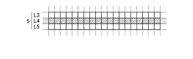
すなわち、例えば図13に示すように、走査線5のラインL3にオン電圧が印加されて各放射線検出素子7のリセット処理が行われた後のリークデータdleakの読み出し処理で読み出されたリークデータdleakの値が閾値dleak_th以上に大きな値になっても、その時点では放射線の照射開始が検出されず、走査線5の次のラインL4にオン電圧が印加されて各放射線検出素子7のリセット処理が行われる。
That is, for example, as shown in FIG. 13, the leak data read in the read processing of the leak data dleak after the on-voltage is applied to the line L <b> 3 of the
そして、その次のリークデータdleakの読み出し処理で、読み出されたリークデータdleakが再度閾値dleak_th以上に大きな値になった場合に、その時点で初めて放射線の照射開始が検出される。なお、図13や後述する図15等において、「R」は各放射線検出素子7のリセット処理が行われることを表し、「L」はリークデータdleakの読み出し処理が行われることを表す。
In the next leak data dleak read process, when the read leak data dleak again becomes a value larger than the threshold value dleak_th, the start of radiation irradiation is detected for the first time. In FIG. 13 and FIG. 15 described later, “R” indicates that the reset process of each
このように、上記のように構成した場合、放射線画像撮影装置1に対して実際に放射線の照射が開始された場合には、放射線の照射が開始されて読み出されたリークデータdleakの値が閾値dleak_th以上の値になった後、少なくとも1回(すなわち上記の例では走査線5のラインL4にオン電圧が印加されて)各放射線検出素子7のリセット処理が行われることになる。
In this way, when configured as described above, when radiation irradiation is actually started with respect to the radiation
そして、走査線5のラインL4にTFT8を介して接続されている各放射線検出素子7では、放射線の照射が開始されて、各放射線検出素子7内で放射線の照射により有用な電荷が発生した後で、少なくとも1回リセット処理が行われる。そのため、それらの各放射線検出素子7では、放射線の照射により有用な電荷がリセット処理により一旦各放射線検出素子7内から除去された後で、改めて放射線の照射により発生した電荷が各放射線検出素子7内に蓄積される状態になる。
In each
そのため、それらの各放射線検出素子7、すなわち上記の例では走査線5のラインL4に接続されている各放射線検出素子7では、それらの各放射線検出素子7から画像データDとして読み出される電荷の一部が上記のようにして欠落してしまうため、それらの各放射線検出素子7から読み出される画像データDのデータ値が本来読み出されるべきデータ値から低下してしまう。
Therefore, in each of the
そのため、後の画像データDの読み出し処理(図13参照)時に、それらの各放射線検出素子7を含む各放射線検出素子7から読み出された画像データD中の、当該各放射線検出素子7に対応する部分(すなわち上記の例では走査線5のラインL4に接続されている各放射線検出素子7に対応する部分)に、データ値が低下した、いわゆる線欠陥が生じてしまう(図14の斜線部分参照)。
Therefore, it corresponds to each
そして、このような線欠陥が生じると、そのような画像データDに基づいて生成された放射線画像中にも、画像データDの線欠陥に対応する位置に線が現れて放射線画像が見づらくなるとともに、線欠陥を画像補正する際に、線欠陥が生じた部分に本来撮影されている情報が、画像補正により放射線画像中から消えてしまう虞れが生じる。 When such a line defect occurs, a line appears at a position corresponding to the line defect in the image data D in the radiation image generated based on the image data D, and the radiation image becomes difficult to see. When the line defect is image-corrected, there is a possibility that information originally captured in the portion where the line defect has occurred disappears from the radiation image due to the image correction.
[線欠陥の発生を防止するための構成等について]
そこで、本実施形態に係る放射線画像撮影装置1では、このような線欠陥が生じることを防止するために、以下のように構成されるようになっている。以下、本実施形態に係る放射線画像撮影装置1の作用についてもあわせて説明する。
[Configurations to prevent the occurrence of line defects]
Therefore, the radiographic
本実施形態では、放射線画像撮影装置1の制御手段22は、上記と同様に、放射線画像撮影前にリークデータdleakの読み出し処理と各放射線検出素子7のリセット処理とを交互に繰り返し行わせる。
In this embodiment, the control means 22 of the radiographic
そして、ある回のリークデータdleakの読み出し処理で読み出したリークデータdleakが設定された閾値dleak_th以上になっても、その時点ですぐに放射線の照射が開始されたとは判断しない点では上記の構成と同様であるが、制御手段22は、読み出したリークデータdleakが閾値dleak_th以上になった場合には、上記と異なり、その直後の各放射線検出素子のリセット処理を行わずに、再度、リークデータdleakの読み出し処理を行うようになっている。 In addition, even if the leak data dleak read out in a certain leak data dleak read processing exceeds the set threshold value dleak_th, it is not determined that radiation irradiation has started immediately at that time. In the same manner, the control means 22 re-leaks the leak data dleak again without performing the reset processing of each radiation detection element immediately after that, when the read leak data dleak is equal to or greater than the threshold dleak_th. Is read out.
すなわち、例えば図15に示すように、走査線5のラインL3にオン電圧が印加されて各放射線検出素子7のリセット処理が行われた後のリークデータdleakの読み出し処理で読み出されたリークデータdleakの値が閾値dleak_th以上に大きな値になっても、制御手段22は、その時点では放射線の照射が開始されたとは判断しない。そして、その直後の各放射線検出素子7のリセット処理、すなわちこの例では走査線5の次のラインL4へのオン電圧の印加を行わない。
That is, for example, as shown in FIG. 15, the leak data read in the read processing of the leak data dleak after the on-voltage is applied to the line L <b> 3 of the
そして、図15に示すように、走査線5の次のラインL4へのオン電圧の印加を行わず、各放射線検出素子7のリセット処理を行わないまま、次の読み出し処理のタイミングでリークデータdleakの読み出し処理を行う。そして、当該次の読み出し処理で読み出されたリークデータdleakが再度閾値dleak_th以上に大きな値になった場合に、その時点で初めて放射線の照射が開始されたと判断し、放射線の照射開始を検出して、各機能部に対して放射線の照射開始の検出後の各処理を行わせる。
Then, as shown in FIG. 15, the on-voltage is not applied to the next line L4 of the
具体的には、制御手段22は、上記のようにして放射線の照射が開始されたことを検出すると、図15に示すように、ゲートドライバー15bから走査線5の全てのラインL1〜Lxにオフ電圧を印加させ、各TFT8をオフ状態にして、放射線の照射により各放射線検出素子7内で発生した電荷が各放射線検出素子7内に蓄積されるようにする電荷蓄積状態に移行させる。
Specifically, when the control means 22 detects that radiation irradiation has been started as described above, the control means 22 turns off all the lines L1 to Lx of the
そして、制御手段22は、例えば放射線の照射開始を検出してから所定時間だけ電荷蓄積状態を継続した後、画像データDの読み出し処理を行わせるように構成される。 For example, the control means 22 is configured to read out the image data D after continuing the charge accumulation state for a predetermined time after detecting the start of radiation irradiation.
その際、本実施形態では、制御手段22は、図15に示すように、放射線の照射開始を検出する前にオン電圧が最後に印加された走査線5(図15の場合は走査線5のラインL3)の次にオン電圧を印加すべき走査線5(図15の場合は走査線5のラインL4)からオン電圧の印加を開始し、ゲートドライバー15bから各走査線5にオン電圧を順次印加させて、画像データDの読み出し処理を行うようになっている。
At this time, in this embodiment, as shown in FIG. 15, the
また、制御手段22は、上記のようにして、画像データDの読み出し処理を終了すると、続いて、オフセットデータOの読み出し処理を行うようになっている。
In addition, when the reading process of the image data D is completed as described above, the
そして、本実施形態では、図示を省略するが、制御手段22は、オフセットデータOの読み出し処理では、図13に示した画像データDの読み出し処理までの処理シーケンスと同じ処理シーケンスを繰り返してオフセットデータOの読み出し処理を行うようになっている(後述する図21参照)。 In the present embodiment, although not shown, the control means 22 repeats the same processing sequence as the processing sequence up to the reading processing of the image data D shown in FIG. O reading processing is performed (see FIG. 21 described later).
すなわち、画像データDの読み出し処理の終了後、上記の検出方法の場合にはリークデータdleakの読み出し処理と各放射線検出素子7のリセット処理を所定回数行った後、電荷蓄積状態に移行させ、その後、オフセットデータOの読み出し処理が行われる。
That is, after the reading process of the image data D is completed, in the case of the above detection method, the reading process of the leak data dleak and the reset process of each
そして、制御手段22は、オフセットデータOの読み出し処理が終了すると、コンソール58(図7や図8参照)等の画像処理装置に対して、各放射線検出素子7ごとに読み出した画像データDやオフセットデータOを送信するようになっている。また、放射線画像撮影装置1から、プレビュー画像用のデータを適宜のタイミングでコンソール58に送信するように構成することも可能である。
Then, when the reading process of the offset data O is completed, the
一方、制御手段22は、例えば、上記のように走査線5のラインL3にオン電圧が印加されて各放射線検出素子7のリセット処理が行われた後のリークデータdleakの読み出し処理で読み出されたリークデータdleakの値が閾値dleak_th以上に大きな値になり、その直後の各放射線検出素子7のリセット処理(すなわちこの例では走査線5の次のラインL4へのオン電圧の印加)を行わずに、次の読み出し処理のタイミングで読み出したリークデータdleakの値が、閾値dleak_th未満であった場合には、放射線の照射開始が誤検出されたと判断するようになっている。
On the other hand, for example, the control means 22 is read out in the read processing of the leak data dleak after the on-voltage is applied to the line L3 of the
そして、この場合は、制御手段22は、図16に示すように、再度、読み出したリークデータdleakの値が閾値dleak_th未満であり誤検出と判断した直後から各放射線検出素子7のリセット処理を再開して、リークデータdleakの読み出し処理と各放射線検出素子7のリセット処理とを繰り返し行わせる状態に戻すように構成される。
In this case, as shown in FIG. 16, the control means 22 resumes the reset process of each
上記のように構成した場合、前述したように、リークデータdleakが閾値dleak_th以上になった次の読み出し処理でリークデータdleakが再度閾値dleak_th以上になったか否かによって、放射線画像撮影装置1に対する放射線の照射開始を検出したか、或いは照射開始を誤検出したかを的確に判別することが可能となる。
When configured as described above, as described above, depending on whether or not the leak data dleak becomes equal to or higher than the threshold value dleak_th in the next read processing after the leak data dleak becomes equal to or higher than the threshold value dleak_th, the radiation to the
そして、一旦、閾値dleak_th以上となったリークデータdleakが、次の読み出し処理で読み出された際にも閾値dleak_th以上の値になった場合には、放射線画像撮影装置1に対して放射線の照射が開始されたと的確に判断して、走査駆動手段15や読み出し回路17等の各機能部に放射線の照射が開始された場合の各処理を的確に行わせて、各放射線検出素子7から画像データDを的確に読み出すことが可能となる。
When the leak data dleak that has become equal to or greater than the threshold value dleak_th once becomes a value that is equal to or greater than the threshold value dleak_th even when it is read out in the next reading process, the radiation
また、一旦、閾値dleak_th以上となったリークデータdleakが、次の読み出し処理で読み出された際に閾値dleak_th未満の値になった場合には、放射線画像撮影装置1に振動等が加わったり静電気が生じる等したためであり、放射線の照射開始が誤検出されたと的確に判断して、再度、放射線の照射開始の検出処理を行う状態に的確に戻ることが可能となる。
In addition, when the leak data dleak that has exceeded the threshold value dleak_th once becomes a value that is less than the threshold value bleak_th when read in the next reading process, vibration or the like is applied to the radiographic
一方、本実施形態では、1回目の読み出し処理で読み出されたリークデータdleakが閾値dleak_th以上になった場合には、図15等に示したように、その直後の各放射線検出素子7のリセット処理(すなわち図15等の例では走査線5のラインL4にオン電圧が印加されて行われる各放射線検出素子7のリセット処理)を行わない。
On the other hand, in the present embodiment, when the leak data dleak read in the first reading process is equal to or higher than the threshold dleak_th, as shown in FIG. Processing (that is, in the example of FIG. 15 and the like, reset processing of each
そのため、読み出されるリークデータdleakの値が閾値dleak_th以上になった原因が放射線画像撮影装置1に対する放射線の照射によるものであった場合、その直後の各放射線検出素子7のリセット処理が行われないため、放射線の照射により各放射線検出素子7内で発生し、蓄積された有用な電荷がリセット処理で各放射線検出素子7内から失われることを防止することが可能となる。
Therefore, when the cause of the read leak data dleak being equal to or greater than the threshold dleak_th is due to radiation irradiation to the
そのため、後の画像データDの読み出し処理(図15参照)時に各放射線検出素子7から読み出された画像データDの中に図14に示したような線欠陥が生じることを防止することが可能となる。
Therefore, it is possible to prevent a line defect as shown in FIG. 14 from occurring in the image data D read from each
なお、図15では、放射線画像撮影装置1に対する放射線の照射開始が、走査線5のラインL3にオン電圧が印加されてリセット処理が行われた後に行われた場合が示されている。
Note that FIG. 15 shows a case where the radiation irradiation start to the
この場合、走査線5のラインL2にオン電圧が印加されて行われたリセット処理の直後の読み出し処理で読み出されたリークデータdleakの値は、放射線の照射開始前であるため閾値dleak_th未満の値であり、走査線5のラインL3にオン電圧が印加されて行われたリセット処理の直後の読み出し処理で読み出されたリークデータdleakの値は、放射線の照射開始後であるため閾値dleak_th以上の値になる。
In this case, the value of the leak data dleak read out in the readout process immediately after the reset process performed by applying the on-voltage to the line L2 of the
しかし、例えば図17に示すように、最初に閾値dleak_th以上のリークデータdleakが読み出される読み出し処理の直前の、走査線5のラインL3にオン電圧が印加されてリセット処理が行われる直前或いはリセット処理が行われている最中に、放射線の照射が開始される場合もある。
However, for example, as shown in FIG. 17, immediately before the read process in which the leak data dleak having the threshold value dleak_th or more is first read out, immediately before the reset process is performed by applying the ON voltage to the line L3 of the
そして、この場合も、図15に示した場合と同様に、走査線5のラインL2にオン電圧が印加されて行われたリセット処理の直後の読み出し処理で読み出されたリークデータdleakの値は、放射線の照射開始前であるため閾値dleak_th未満の値であり、走査線5のラインL3にオン電圧が印加されて行われたリセット処理の直後の読み出し処理で読み出されたリークデータdleakの値は、放射線の照射開始後であるため閾値dleak_th以上の値になる。
Also in this case, as in the case shown in FIG. 15, the value of the leak data dleak read in the read process immediately after the reset process performed by applying the on-voltage to the line L2 of the
そして、図15に示した場合も図17に示した場合も、いずれの場合も、リークデータdleakの値が閾値dleak_th以上の値になった読み出し処理の直後の各放射線検出素子7のリセット処理は行われず、再度行われた読み出し処理でリークデータdleakの値が閾値dleak_th以上になるため、放射線の照射開始が検出される。
In both cases shown in FIG. 15 and FIG. 17, the reset process of each
図17に示した例では、図15の場合と同様に、リークデータdleakの値が閾値dleak_th以上の値になった読み出し処理の直後の各放射線検出素子7のリセット処理は行われないため、少なくともこの部分で画像データD中に線欠陥が発生することは防止することができる。
In the example shown in FIG. 17, as in the case of FIG. 15, the reset process of each
しかし、走査線5のラインL3にオン電圧が印加されて行われた各放射線検出素子7のリセット処理は行われるため、画像データD中の走査線5のラインL3に接続されている各放射線検出素子7に対応する部分に線欠陥が生じる可能性が残る(図18の斜線部分参照)。
However, since the reset processing of each
このように、本実施形態に係る放射線画像撮影装置1の上記の特徴的な構成をもってしても、読み出される画像データD中に線欠陥が生じることを必ずしも確実に防止することができるとまでは言い切れない。
Thus, even with the above-described characteristic configuration of the radiographic
しかし、図17に示したような場合に、従来のように、リークデータdleakの値が閾値dleak_th以上の値になった読み出し処理の直後に各放射線検出素子7のリセット処理を行うように構成すると、発生する線欠陥は、図19に示すように少なくとも2本連続して発生する状態になる。
However, in the case shown in FIG. 17, if the configuration is such that the reset processing of each
そして、図18と図19とを比較して分かるように、本実施形態のように、リークデータdleakの値が閾値dleak_th以上の値になった読み出し処理の直後の各放射線検出素子7のリセット処理を行わないように構成すれば、必ずしも画像データD中に線欠陥が発生すること自体を防止できるとは言えないとしても、画像データD中に現れ得る線欠陥の数が不必要に増大することを防止することが可能となり、発生する線欠陥を的確に軽減することが可能となる。
Then, as can be seen by comparing FIG. 18 and FIG. 19, as in the present embodiment, the reset process of each
そして、例えば図19に示したように、線欠陥が複数本連続して発生する場合、その線欠陥の部分に例えば患者の病変部等の重要な部分が撮影されていると、線欠陥の画像補正の際に、撮影されているはずの病変部が画像補正で放射線画像中から消えてしまう、或いは見難くなってしまう可能性が生じる。 For example, as shown in FIG. 19, when a plurality of line defects occur continuously, if an important part such as a lesion part of a patient is photographed in the line defect part, an image of the line defect is obtained. At the time of correction, there is a possibility that a lesion portion that should have been photographed disappears from the radiographic image or becomes difficult to see due to image correction.
しかし、本実施形態では、線欠陥が生じず、或いは線欠陥が生じるとしても図18に示したように1本程度しか生じない。そして、患者の病変部は、通常、1本の線欠陥よりも幅が大きい。そのため、例えば線欠陥が患者の病変部等を横切るように発生しても、病変部等が正常に撮影された、線欠陥に隣接する部分等の正常な画像データDを用いて、線欠陥の部分を画像補正することで、患者の病変部等の重要な部分を的確に復元することが可能となる。 However, in this embodiment, no line defect occurs, or even if a line defect occurs, only about one line defect occurs as shown in FIG. A patient's lesion is usually wider than a single line defect. Therefore, for example, even if a line defect occurs so as to cross a lesioned part or the like of a patient, the line defect is detected using normal image data D such as a part adjacent to the line defect in which the lesioned part is normally imaged. By correcting the image of the portion, it is possible to accurately restore an important portion such as a lesioned part of the patient.
そのため、患者の病変部等の重要な部分が、画像補正によって放射線画像中から消えてしまったり見難くなってしまうことを的確に防止することが可能となり、患者の病変部等の重要な部分が的確に撮影された放射線画像を得ることが可能となる。 Therefore, it is possible to accurately prevent an important part such as a lesion part of a patient from disappearing or becoming difficult to see from a radiographic image by image correction, and an important part such as a patient lesion part is prevented. It is possible to obtain a radiographic image photographed accurately.
[効果]
以上のように、本実施形態に係る放射線画像撮影装置1および放射線画像撮影システム50によれば、放射線画像撮影装置1の制御手段22は、読み出したリークデータdleakが設定された閾値dleak_th以上になった場合、その直後の各放射線検出素子のリセット処理を行わせないように構成される。
[effect]
As described above, according to the radiographic
そして、再度、リークデータdleakの読み出し処理を行わせ、再度の読み出し処理で読み出されたリークデータdleakが、再度、閾値dleak以上であった場合には、放射線の照射が開始されたと判断する。そして、各機能部に放射線の照射が開始された場合の各処理を行わせる。 Then, the leak data dleak is read again, and if the leak data dleak read by the second read process is equal to or higher than the threshold value dleak, it is determined that radiation irradiation has started. Then, each function unit is caused to perform each process when radiation irradiation is started.
また、再度の読み出し処理で読み出されたリークデータdleakが閾値dleak_th未満であった場合には、放射線の照射開始が誤検出されたと判断する。そして、再度、リークデータdleakの読み出し処理と各放射線検出素子7のリセット処理とを繰り返し行わせる状態に戻す。
In addition, when the leak data dleak read out by the re-reading process is less than the threshold dleak_th, it is determined that the start of radiation irradiation has been erroneously detected. And it returns to the state which repeats the read-out process of leak data dleak, and the reset process of each
放射線画像撮影装置1に放射線が照射された場合には、読み出されるリークデータdleakの値が大きくなった状態で維持されるが、放射線画像撮影装置1に振動等が加わったり静電気が生じた場合等にはリークデータdleakの値は瞬間的には大きくなるものの、すぐに元の小さな値に戻る。
When the radiation
そのため、上記のように構成し、読み出したリークデータdleakの値が2回以上、閾値dleak_th以上の値になれば、放射線画像撮影装置1に対する放射線の照射が開始されたことを意味する。そして、そのような場合に、放射線画像撮影装置1の制御手段22が、放射線の照射が開始されたと判断するように構成することで、放射線の照射開始を的確に検出することが可能となる。
For this reason, if the value of the leak data dleak that is configured as described above is equal to or greater than the threshold value dleak_th twice or more, it means that the
また、一旦閾値dleak_th以上に大きな値になったリークデータdleakが次の読み出し処理では閾値dleak_th未満の小さな値になれば、放射線画像撮影装置1に振動等が加わったり静電気が生じたこと等を意味する。少なくとも、放射線の照射が開始されたことを意味するものではない。
In addition, if the leak data dleak once larger than the threshold value dleak_th becomes a small value less than the threshold value bleak_th in the next reading process, it means that the
そして、そのような場合に、放射線画像撮影装置1の制御手段22が、放射線の照射開始が誤検出されたと判断するように構成することで、放射線画像撮影装置1に振動等が加わったり静電気が生じたような場合に、放射線の照射開始を誤検出することを的確に防止することが可能となる。
In such a case, the
そして、再度、リークデータdleakの読み出し処理と各放射線検出素子7のリセット処理とを繰り返し行わせる状態に戻すことで、例えば、その後、すぐに実際に放射線の照射が開始された場合でも、それを的確に検出して放射線画像撮影を的確に行うことが可能となる。
Then, by returning again to the state in which the readout process of the leak data dleak and the reset process of each
また、読み出されたリークデータdleakの値が一旦閾値dleak_th以上に大きくなった場合に、その直後の各放射線検出素子7のリセット処理を行わせないように構成することで、実際に放射線の照射が開始されている場合にリセット処理を行ってしまい、放射線の照射により各放射線検出素子7内で発生し蓄積された有用な電荷がリセット処理によって失われてしまうことを的確に防止することが可能となる。
In addition, when the value of the read leak data dleak once becomes greater than or equal to the threshold value dleak_th, the
そのため、後の画像データDの読み出し処理(図15参照)時に各放射線検出素子7から読み出された画像データDの中に図14に示したような線欠陥が生じることを的確に防止し、或いは、発生する線欠陥を的確に軽減することが可能となる。
Therefore, it is possible to accurately prevent the occurrence of a line defect as shown in FIG. 14 in the image data D read from each
[オフセットデータOの読み出し処理について]
なお、図16に示したように、放射線画像撮影装置1に振動が加わる等して放射線の照射開始が誤検出された場合には、各放射線検出素子7のリセット処理が1回分行われずに放射線の照射開始の検出処理(すなわち交互に行われるリークデータdleakの読み出し処理と各放射線検出素子7のリセット処理)が再開される。すなわち、各放射線検出素子7のリセット処理が、1回分だけタイミングが後側にずれるようにして再開される。
[Reading process of offset data O]
In addition, as shown in FIG. 16, when the irradiation start of radiation is erroneously detected due to vibration applied to the radiation
これをより一般的に表すと、図20に示すように、例えば走査線5のラインLmにオン電圧が印加された直後のリークデータdleakの読み出し処理(図中では図示を省略。図16等参照)で読み出されたリークデータdleakが閾値dleak_th以上の値になり、その直後のリセット処理が行われず、次の読み出し処理で読み出されたリークデータdleakが閾値dleak_th未満になったため、誤検出と判断されて、走査線5のラインLm+1からオン電圧の印加が再開されて各放射線検出素子7のリセット処理が再開される。
More generally, as shown in FIG. 20, for example, the leakage data dleak read processing immediately after the on-voltage is applied to the line Lm of the scanning line 5 (not shown in the drawing, see FIG. 16 and the like). Since the leak data dleak read in step) becomes a value equal to or larger than the threshold value dleak_th, the reset process immediately after that is not performed, and the leak data dleak read out in the next read process becomes less than the threshold value dleak_th. As a result, the application of the ON voltage is resumed from the line Lm + 1 of the
そして、例えば走査線5のラインLnにオン電圧が印加された直後のリークデータdleakの読み出し処理で読み出されたリークデータdleakが閾値dleak_th以上の値になり、その直後のリセット処理が行われず、次の読み出し処理で読み出されたリークデータdleakが再度閾値dleak_th以上になったため、放射線の照射開始が検出された場合を考える。
For example, the leak data dleak read in the read process of the leak data dleak immediately after the on-voltage is applied to the line Ln of the
この場合、前述したように、放射線画像撮影装置1の制御手段22は、放射線の照射開始を検出すると、走査駆動手段15のゲートドライバー15bから走査線5の各ラインL1〜Lxにオフ電圧を印加して各TFT8をオフ状態にして電荷蓄積状態に移行させる。そして、所定時間後に、走査線5の各ラインLn+1からオン電圧の印加を開始させて、画像データDの読み出し処理を行わせる。
In this case, as described above, the
その際、各放射線検出素子7内では、各放射線検出素子7自体の熱(温度)による熱励起等によりいわゆる暗電荷(暗電流ともいう。)が常時発生しており、この暗電荷によるオフセット分が、後の画像データDの読み出し処理で読み出される画像データDに重畳される。
At that time, a so-called dark charge (also referred to as dark current) is constantly generated in each
そして、この暗電荷によるオフセット分は、画像データDの読み出し処理前にTFT8がオフ状態とされている間、すなわち図20における時間Tac1やTac2等の間(なお、以下、この時間Tacを実効蓄積時間という。)に各放射線検出素子7内に蓄積される暗電荷の量によってその大きさが決まり、実効蓄積時間Tacが異なれば、蓄積される暗電荷の量が変わり、暗電荷によるオフセット分の大きさも変わる。
The offset due to the dark charge is stored while the
図20に示した場合、走査線5のラインLmにオン電圧が印加された後、次の走査線5のラインLm+1にオン電圧が印加されるタイミングが、放射線の照射開始の誤検出によってリセット処理を行わなかった1タイミング分だけ後側にずれている。そして、少なくとも、走査線5のラインLmとラインLm+1とでは、走査線5のラインLmの実効蓄積時間Tac1が、走査線5のラインLm+1の実効蓄積時間Tac2よりも上記のタイミングのずれの分だけ長くなる。
In the case illustrated in FIG. 20, after the on-voltage is applied to the line Lm of the
そのため、走査線5のラインLmに接続されている各放射線検出素子7から読み出される画像データDに重畳される暗電荷によるオフセット分は、上記の実効蓄積時間Tac1、Tac2の違いの分だけ、走査線5のラインLm+1に接続されている各放射線検出素子7から読み出される画像データDに重畳される暗電荷によるオフセット分よりも大きくなる。
For this reason, the offset due to the dark charge superimposed on the image data D read from each
このように、上記のように読み出されたリークデータdleakの値が閾値dleak_th以上になった場合にその直後の各放射線検出素子7のリセット処理を行わないように構成した場合、各放射線検出素子7のリセット処理における走査線5の各ラインLに対するオン電圧の印加のタイミングがずれる分だけ、走査線5ごとの実効蓄積時間Tacが変わってしまう。
As described above, when the value of the leak data dleak read out as described above is equal to or greater than the threshold value dleak_th, the reset process of each
そのため、各放射線検出素子7から読み出される画像データDに重畳される暗電荷によるオフセット分が走査線5ごとに異なる値になってしまう。そのため、例えば、仮に放射線画像撮影装置1の放射線入射面R(図1等参照)に一様に同じ線量の放射線を照射した場合であっても、読み出される画像データD(暗電荷によるオフセット分を含む。)が走査線5ごとに異なる値になるといった問題が発生する。
Therefore, the offset due to the dark charge superimposed on the image data D read from each
しかし、前述したように、オフセットデータOの読み出し処理を行う際に、放射線の照射開始の検出処理から画像データDの読み出し処理までの処理シーケンスと同じ処理シーケンスを繰り返してオフセットデータOの読み出し処理を行うように構成することで、上記のような問題が発生してもそれを的確に解消することが可能となる。 However, as described above, when the offset data O is read, the offset data O is read by repeating the same processing sequence as the processing sequence from the radiation irradiation start detection process to the image data D read process. By configuring so as to perform, even if the above problem occurs, it can be solved accurately.
すなわち、例えば画像データDの読み出し処理までの各処理が図20に示したような処理シーケンスに従って行われた場合、図21に示すように、画像データDの読み出し処理後、図20に示した処理シーケンスと同じ処理シーケンスを繰り返して行うようにしてオフセットデータOの読み出し処理を行うように構成する。 That is, for example, when each process up to the reading process of the image data D is performed according to the processing sequence as shown in FIG. 20, the processing shown in FIG. 20 is performed after the reading process of the image data D as shown in FIG. The offset data O is read out by repeating the same processing sequence as the sequence.
なお、この場合、オフセットデータOは、画像データDに重畳されている暗電荷によるオフセット分に相当するものであるから、放射線画像撮影装置1には放射線は照射されない。そのため、オフセットデータOの読み出し処理の際には、放射線の照射開始の検出処理を行う必要はない。図21で、「放射線の照射開始の検出処理」ではなく「検出動作」と記載されている理由は、このように、リークデータdleakの読み出し処理や各放射線検出素子7のリセット処理は行うが、読み出したリークデータdleakに基づく放射線の照射開始の判定処理までは行わないことを表している。判定処理を行う必要がないからである。
In this case, since the offset data O corresponds to the offset due to the dark charge superimposed on the image data D, the radiation
オフセットデータOの読み出し処理を上記のように構成すると、前述したように、走査線5が異なると実効蓄積時間Tacが異なるとしても、走査線5ごとに見た場合、画像データDの読み出し処理の際の実効蓄積時間TacとオフセットデータOの読み出し処理の際の実効蓄積時間Tacとが同じ時間になる。
When the reading process of the offset data O is configured as described above, as described above, even if the effective accumulation time Tac is different when the
すなわち、具体的に言えば、上記のように例えば誤検出があったために、走査線5のラインLmにおける実効蓄積時間Tac1と走査線5のラインLm+1における実効蓄積時間Tac2とが異なる時間になったとしても、走査線5のラインLmにおける画像データDの読み出し処理の際の実効蓄積時間Tac1とオフセットデータOの読み出し処理の際の実効蓄積時間Tac1は、処理シーケンスが同じであるから同じ時間になる。また、走査線5のラインLm+1においても画像データDの読み出し処理の際の実効蓄積時間Tac2とオフセットデータOの読み出し処理の際の実効蓄積時間Tac2とが同じ時間になる。
Specifically, for example, as described above, because of a false detection, the effective accumulation time Tac1 in the line Lm of the
そのため、いずれの走査線5においても、画像データDの読み出し処理の際の実効蓄積時間TacとオフセットデータOの読み出し処理の際の実効蓄積時間Tacとが同じ時間になるため、各放射線検出素子7から読み出された画像データDに重畳されている暗電荷によるオフセット分と、オフセットデータOの読み出し処理で読みされたオフセットデータOとが同じ値になる。
Therefore, in any
そのため、各放射線検出素子7ごとに、読み出された画像データDからオフセットデータOを下記(1)式に従って減算することで、画像データDに重畳されている暗電荷によるオフセット分とオフセットデータOとが相殺され、算出される真の画像データD*が暗電荷によるオフセット分を含まない値になる。
D*=D−O …(1)
Therefore, the offset data O and the offset data O due to the dark charges superimposed on the image data D are subtracted from the read image data D according to the following equation (1) for each
D * = DO (1)
すなわち、上記のようにして算出される真の画像データD*では、実効蓄積時間Tacの長短による値の違いがなくなり、放射線の照射により各放射線検出素子7内で発生した電荷のみに起因した値になる。従って、読み出された画像データDそのものではなく、このようにして算出される真の画像データD*に基づいて放射線画像を生成することで、実効蓄積時間Tacの長短による暗電荷によるオフセット分の大小の影響を受けない状態で放射線画像を生成することが可能となる。
That is, in the true image data D * calculated as described above, there is no difference in value due to the length of the effective accumulation time Tac, and the value is caused only by the charges generated in each
[変形例について]
一方、図15や図16等では、放射線の照射開始の検出処理において、走査駆動手段15から走査線5の最初のラインL1から順にオン電圧を順次印加して各放射線検出素子7のリセット処理を行う場合について説明した。しかし、例えば、放射線画像撮影装置1の検出部P(図2や図3参照)が、図22に示すように、4つの領域Pa〜Pd等に分割されるように構成されている場合がある。
[Modification]
On the other hand, in FIG. 15 and FIG. 16 and the like, in the detection process of radiation irradiation start, the on-voltage is sequentially applied from the
そして、このような場合、例えば図23に示すように、検出部Pの領域Pa〜Pd(図22参照)上の各走査線5のうち、検出部Pの両端側に配置された各走査線5、すなわち領域Pa、Pbの走査線5のラインL1および領域Pc、Pdの走査線5のラインLxから順に交互に、検出部Pの中心部の走査線5(図23では図示省略)に向かってオン電圧を印加する走査線5をシフトさせながら、各放射線検出素子7のリセット処理を行うように構成することが可能である。
In such a case, for example, as shown in FIG. 23, among the
また、図23に示したように、領域Pa、Pbと領域Pc、Pdとで各走査線5にオン電圧を印加するタイミングをずらさずに、例えば図24に示すように、各領域Pa〜Pdで複数の走査線5にオン電圧を同時に印加しながら、オン電圧を印加する走査線5をシフトするように構成することも可能である。
Further, as shown in FIG. 23, for example, as shown in FIG. 24, each region Pa to Pd is not shifted without shifting the timing of applying the ON voltage to each
さらに、例えば図25に示すように、領域Pa、Pbと領域Pc、Pdとでリークデータdleakの読み出し処理と各放射線検出素子7のリセット処理を行うタイミングをずらして、各走査線5にオン電圧を順次印加するように構成することも可能である。
Further, for example, as shown in FIG. 25, the on-voltage is applied to each
なお、図23〜図25では、いわば外側の走査線5から内側の走査線5に向けてオン電圧を印加する走査線5をシフトする場合を記載したが、図示を省略するが、逆に、内側の走査線5から外側の走査線5に向けてオン電圧を印加する走査線5をシフトするように構成することも可能である。
In FIG. 23 to FIG. 25, the case where the
上記のいずれの変形例においても、また、その他のさらなる変形例においても、放射線画像撮影装置1の制御手段22は、上記の実施形態と同様に、1回の読み出し処理で読み出されたリークデータdleakが閾値dleak_th以上になっても、その時点では放射線の照射開始を検出せず、再度読み出されたリークデータdleakが閾値dleak_th以上になった場合に、その時点で放射線の照射開始を検出する。
In any of the above-described modification examples and other further modification examples, the
2回目の読み出し処理で読み出されたリークデータdleakが閾値dleak_th未満の場合は、誤検出として、検出処理を再開させる。そして、1回目にリークデータdleakが閾値dleak_th以上になった直後の各放射線検出素子7のリセット処理は行わない。
If the leak data dleak read in the second reading process is less than the threshold dleak_th, the detection process is restarted as a false detection. And the reset process of each
このように構成することで、上記の実施形態における有益な効果を、変形例においても的確に発揮させることが可能となる。 By comprising in this way, the beneficial effect in said embodiment can be exhibited precisely also in a modification.
なお、上記の変形例で、例えば領域Pa、Pbでのリークデータdleakの読み出し処理で読み出されたリークデータdleakが閾値dleak_th以上になった場合、2回目の読み出し処理でリークデータdleakが閾値dleak_th以上になったか否かの判定処理を、それとは別の領域である領域Pc、Pdで読み出されたリークデータdleakに基づいて行ってしまうと、以下のような問題が生じ得る。 In the above modification, for example, when the leak data dleak read in the leak data dleak read processing in the regions Pa and Pb is equal to or greater than the threshold value dleak_th, the leak data dleak becomes the threshold value dleak_th in the second read processing. If the determination process of whether or not the above is performed based on the leak data dleak read in the areas Pc and Pd which are different areas, the following problems may occur.
すなわち、例えば、放射線画像撮影装置1の検出部Pの領域Paや領域Pbにのみ放射線が照射されるように照射野が狭められた状態で放射線が照射された場合、放射線画像撮影装置1に対する放射線の照射が開始されると、領域Pa、Pbでのリークデータdleakの読み出し処理で読み出されたリークデータdleakが閾値dleak_th以上になる。
That is, for example, when radiation is irradiated in a state where the irradiation field is narrowed so that the radiation is irradiated only to the area Pa and the area Pb of the detection unit P of the
しかし、領域Pcや領域Pdには放射線が照射されないため、領域Pc、Pdでのリークデータdleakの読み出し処理で読み出されたリークデータdleakは閾値dleak_th未満のままである。 However, since the region Pc and the region Pd are not irradiated with radiation, the leak data dleak read out in the read processing of the leak data dleak in the regions Pc and Pd remains less than the threshold value dleak_th.
そのような状態で、上記のように、1回目のリークデータdleakの読み出し処理を行う領域と2回目のリークデータdleakの読み出し処理を行う領域を変えてしまうと、領域Paや領域Pbのみではあるが放射線画像撮影装置1に対して放射線が照射されているにもかかわらず、1回目の読み出し処理で閾値dleak_th以上になったリークデータdleakが、2回目の読み出し処理では閾値dleak_th未満となり、制御手段22は、放射線画像撮影装置1に振動が加わる等して放射線の照射開始を誤検出したものと判断してしまうことになる。しかし、これでは、放射線画像撮影装置1に対する放射線の照射開始を的確に検出することができなくなる。
In such a state, as described above, if the region where the first leak data dleak is read and the region where the second leak data dleak is read are changed, only the region Pa and the region Pb are present. Although the radiation
そのため、上記のように、放射線画像撮影装置1の検出部Pを複数の領域に分割する場合には、リークデータdleakが2回連続して閾値dleak_th以上になったか否かの判定処理は、同じ領域での読み出し処理で読み出されたリークデータdleakについて行うように構成することが望ましい。
Therefore, as described above, when the detection unit P of the
[コンソールでの表示例について]
一方、上記のように、放射線画像撮影装置1で放射線の照射開始が誤検出された場合に、例えば、1回目の読み出し処理で読み出され閾値dleak_th以上になったリークデータdleakの値がどの程度大きな値であったかを表示して放射線技師等の操作者に伝えるように構成することも可能である。
[Console display examples]
On the other hand, as described above, when the radiation
すなわち、本実施形態に係る放射線画像撮影装置1では、制御手段22は、1回目の読み出し処理で読み出されたリークデータdleakが閾値dleak_th以上であり、2回目の読み出し処理で読み出されたリークデータdleakが閾値dleak_th未満であった場合、上記のように放射線の照射開始を誤検出したとして、放射線の照射開始の検出処理に戻るように構成される。
That is, in the radiographic
その際、1回目の読み出し処理で読み出されたリークデータdleakの値を、放射線画像撮影装置1からコンソール58(図7や図8参照)に送信する。そして、コンソール58は、この値をそのまま表示部58aに表示し、或いはその大きさの程度にあわせて「強」、「弱」等に分類する等して、送信されてきたリークデータdleakの値に対応する表示に変換して表示部58aに表示するように構成することが可能である。
At that time, the value of the leak data dleak read in the first reading process is transmitted from the radiographic
ところで、各放射線検出素子7のスイッチ手段であるTFT8が経年劣化する等して、図9に示した各TFT8を介して各放射線検出素子7から信号線6にリークする電荷qが多くなり、読み出されるリークデータdleakにいわばオフセットが重畳されたような状態になって、読み出されるリークデータdleakが大きくなる場合がある。
By the way, the
また、放射線画像撮影装置1を用いる環境が変わったりした場合には、読み出されるリークデータdleakに重畳されるノイズの振幅が大きくなる場合もある。
In addition, when the environment in which the radiographic
そして、いずれの場合も、それらの影響で、図11に示した放射線の照射開始時点(図中の時刻t1参照)より前に読み出されるリークデータdleakが大きくなり、放射線画像撮影装置1に放射線が照射されていないにもかかわらず、ノイズ等の影響で読み出されるリークデータdleakが大きくなって閾値dleak_th以上になって、放射線の照射が開始されたと誤検出されてしまう虞れがある。 In any case, the leakage data dleak read before the radiation irradiation start time (see time t1 in the figure) shown in FIG. In spite of no irradiation, there is a possibility that the leak data dleak read out due to the influence of noise or the like becomes larger than the threshold dleak_th and erroneously detected that the irradiation of radiation has started.
一方、上記の実施形態では、図15等に示したように、放射線の照射開始が検出されると、各放射線検出素子7のリセット処理が停止されて電荷蓄積状態に移行するが、その際、リークデータdleakの読み出し処理も停止される。
On the other hand, in the above embodiment, as shown in FIG. 15 and the like, when the start of radiation irradiation is detected, the reset processing of each
しかし、仮にリークデータdleakの読み出し処理を放射線の照射開始の検出後も継続するように構成した場合(なお、その際、各放射線検出素子7のリセット処理は停止される。)、読み出されるリークデータdleakは例えば図26に示すように、閾値dleak_thより大きな値になって推移する。
However, if the readout process of the leak data dleak is configured to continue even after the detection of the start of radiation irradiation (in this case, the reset process of each
そして、TFT8の経年劣化等が生じると、この放射線の照射開始後のリークデータdleakの値が経年的に小さくなっていく場合がある。そして、照射開始後のリークデータdleakの値が小さくなってしまうと、放射線画像撮影装置1に放射線が照射されても、読み出されるリークデータdleakが閾値dleak_th以上にならなくなる虞れがあり、放射線の照射開始を検出することができなくなる虞れがある。
Then, when the
そこで、例えば図27に示すように、放射線の照射開始の検出前に読み出されたリークデータdleakの値(以下dleak1と表す。)と閾値dleak_thとの差Δd1を算出したり、放射線の照射開始の検出後に読み出されたリークデータdleakの値(以下dleak2と表す。)と閾値dleak_thとの差Δd2を算出して、上記の問題が発生しないように構成することが可能である。 Therefore, for example, as shown in FIG. 27, the difference Δd1 between the leak data dleak value (hereinafter referred to as dleak1) read before the detection of the start of radiation irradiation and the threshold value dleak_th is calculated, or the radiation irradiation start is started. It is possible to calculate the difference Δd2 between the value of leak data dleak (hereinafter referred to as dleak2) read after the detection of the above and the threshold value dleak_th so that the above problem does not occur.
その際、上記の差Δd1、Δd2の算出処理を放射線画像撮影装置1で行うように構成することも可能であり、コンソール58で行うように構成することも可能である。また、これらの算出処理を、常時行うように構成することも可能であり、或いはメンテナンス時等の定期的に、或いは所定の撮影回数ごとに行うように構成することが可能である。さらに、差Δd2を算出するように構成する場合は、上記のように、放射線画像撮影装置1で、放射線の照射開始の検出後もリークデータdleakの読み出し処理を継続するように構成される。
At that time, the calculation process of the above differences Δd1 and Δd2 can be performed by the radiation
閾値dleak_thとの差Δd1、Δd2を算出する対象としては、例えば、放射線の照射開始の検出前に読み出されたリークデータdleak1の最大値や放射線の照射開始の検出後に読み出されたリークデータdleak2の最小値としたり、或いは、放射線の照射開始の検出前や検出後に読み出されたリークデータdleak1、dleak2の各平均値とすることが可能である。 For example, the difference Δd1 and Δd2 with respect to the threshold value dleak_th are calculated as the maximum value of the leak data dleak1 read before the detection of the start of radiation irradiation or the leak data dleak2 read after the detection of the start of radiation irradiation. Or the average values of the leak data dleak1 and bleak2 read before or after the detection of the start of radiation irradiation.
また、コンソール58は、放射線画像撮影装置1が算出して送信してきた上記の差Δd1、Δd2、或いは自らが算出した上記の差Δd1、Δd2を表示部58aに表示し、放射線技師やメンテナンス担当者等がそれらの差Δd1、Δd2を見て、必要に応じて閾値dleak_thを適切な値に設定し直す等の措置をとるように構成することが可能である。
In addition, the
また、例えば図28に示すように、上記の差Δd1、Δd2の絶対値にそれぞれ閾値TH1、TH2で規定される範囲を設定しておき、コンソール58は、上記の差Δd1、Δd2の絶対値が、これらの所定の範囲TH1、TH2内にあり、リークデータdleakの値が閾値dleak_thに近接した場合には、警告を発するように構成することも可能である。
For example, as shown in FIG. 28, ranges defined by the thresholds TH1 and TH2 are set for the absolute values of the differences Δd1 and Δd2, respectively, and the
このように構成すれば、放射線技師やメンテナンス担当者等が警告に応じて閾値dleak_thを適切な値に設定し直す等の必要な措置をとることが可能となる。なお、この場合、警告は、コンソール58の表示部58a上に所定の警告表示を行うように構成してもよく、また、音声等で警告するように構成することも可能である。
With this configuration, it becomes possible for a radiographer, a maintenance person, etc. to take necessary measures such as resetting the threshold value dleak_th to an appropriate value in response to a warning. In this case, the warning may be configured to display a predetermined warning on the
また、上記のようにいきなり警告を発するように構成する代わりに、或いはそれと併用して、例えば図29に示すように、上記の差Δd1の絶対値に閾値TH11、TH12を設定し、上記の差Δd2の絶対値に閾値TH21、TH22を設定しておく。 Also, instead of or in combination with the sudden warning as described above, threshold values TH11 and TH12 are set to the absolute value of the difference Δd1 as shown in FIG. 29, for example. Threshold values TH21 and TH22 are set as absolute values of Δd2.
そして、上記の差Δd1、Δd2の絶対値が閾値TH11や閾値TH21以上である段階であれば、例えば表示部58a上に「GOOD」の表示をする等して、放射線の照射開始の検出前に読み出されるリークデータdleak1がまだ十分に小さく、或いは放射線の照射開始の検出後に読み出されるリークデータdleak2が十分に大きい値である状態であることを報知する。
If the absolute values of the differences Δd1 and Δd2 are at or above the threshold value TH11 or the threshold value TH21, for example, “GOOD” is displayed on the
また、コンソール58は、上記の差Δd1の絶対値が閾値TH11より小さく閾値TH12以上の段階であり、或いは、上記の差Δd2の絶対値が閾値TH21より小さく閾値TH22以上の段階であれば、例えば表示部58a上に「CAUTION」の表示をする等して、放射線の照射開始の検出前に読み出されるリークデータdleak1が若干大きくなったり、或いは放射線の照射開始の検出後に読み出されるリークデータdleak2が若干小さくなっており、注意すべき状態であることを報知して、放射線技師やメンテナンス担当者に注意を喚起する。
Further, the
さらに、コンソール58は、上記の差Δd1の絶対値が閾値TH12より小さい段階であれば、例えば表示部58a上に「DANGER」の表示をする等して、放射線の照射開始の検出前に読み出されるリークデータdleak1が大きくなり、放射線の照射開始が誤検出される虞れがあることを警告して、放射線技師やメンテナンス担当者に注意を喚起する。
Furthermore, if the absolute value of the difference Δd1 is smaller than the threshold value TH12, the
また、上記の差Δd2の絶対値が閾値TH22より小さい段階である場合にも、例えば表示部58a上に「DANGER」の表示をする等して、放射線の照射開始の検出後に読み出されるリークデータdleak2が小さくなり、読み出されるリークデータdleakが閾値dleak_th以上にならなくなって放射線の照射開始を検出できなくなる虞れがあることを警告して、放射線技師やメンテナンス担当者に注意を喚起するように構成することも可能である。なお、上記の各場合において、音声等で報知や注意喚起を行うように構成することも可能である。
Even when the absolute value of the difference Δd2 is smaller than the threshold value TH22, leak data dleak2 read after detection of the start of radiation irradiation, for example, by displaying “DANGER” on the
このように構成した場合も、放射線技師やメンテナンス担当者等が警告に応じて閾値dleak_thを適切な値に設定し直す等の必要な措置をとることが可能となる。 Even in such a configuration, it becomes possible for a radiographer, a maintenance staff, etc. to take necessary measures such as resetting the threshold value dleak_th to an appropriate value in response to a warning.
また、太った患者よりも痩せた患者に放射線を照射する場合の方が、放射線が患者の体内をより透過して放射線画像撮影装置1に到達し易い。すなわち、痩せた患者を撮影する場合の方が読み出されるリークデータdleakの値が大きくなる。そのため、例えば感度が低下し、放射線の照射開始の検出後に読み出されるリークデータdleak2の値が小さくなった放射線画像撮影装置1は、痩せた患者の撮影に用いれば、リークデータdleak2が閾値dleakを十分に越える。そのため、このような放射線画像撮影装置1を痩せた患者専用に用いるように措置することも可能である。
In addition, when a thin patient is irradiated with radiation rather than a fat patient, the radiation is more easily transmitted through the patient's body and reaches the
なお、放射線の照射開始の検出前に読み出されるリークデータdleak1の値や、放射線の照射開始の検出後に読み出されるリークデータdleak2の値、或いは上記の差Δd1、Δd2を時系列的に保存しておき、それらのデータに基づいて放射線画像撮影装置1の使用環境の変化やTFT8の経年劣化の度合い等を把握するように構成することも可能である。
The value of leak data dleak1 read before detection of the start of radiation irradiation, the value of leak data dleak2 read after detection of the start of irradiation of radiation, or the above differences Δd1 and Δd2 are stored in time series. Also, it is possible to determine the change in the usage environment of the radiation
そして、上記の構成例では、上記の差Δd1、Δd2等の表示を見た放射線技師やメンテナンス担当者等が、必要に応じて閾値dleak_thを適切な値に設定し直す等の措置をとる場合について説明したが、コンソール58や放射線画像撮影装置1が、上記の時系列的に保存されたリークデータdleak1、dleak2、差Δd1、Δd2の値の変動等に基づいて、自動的に閾値dleak_thを適切な値に設定し直す等の必要な措置をとるように構成することも可能である。
In the above configuration example, a radiographer or a maintenance person who has seen the display of the difference Δd1, Δd2, etc. takes measures such as resetting the threshold value drak_th to an appropriate value as necessary. As described above, the
また、上記のように、放射線の照射開始が検出された後もリークデータdleakの読み出し処理を継続する(各放射線検出素子7のリセット処理は停止する。)ように構成する代わりに、図15等に示したように、放射線の照射開始を検出した時点でリークデータdleakの読み出し処理を各放射線検出素子7のリセット処理とともに停止する。そして、上記の放射線の照射開始の検出後に読み出されるリークデータdleak2の値については、後で読み出した画像データDの値から推定して用いるように構成することも可能である。
Further, as described above, instead of being configured to continue the reading process of the leak data dleak even after the start of radiation irradiation is detected (the reset process of each
この場合、リークデータdleakは、単位時間あたりに放射線画像撮影装置1に照射されている放射線の線量すなわち線量率に依存する値になるのに対し、画像データDは、放射線の線量、すなわち放射線の照射が開始されてから終了するまでの間に照射された放射線の線量に依存する値になる。
In this case, the leak data dleak has a value that depends on the dose of radiation applied to the
そのため、上記のように後で読み出した画像データDの値から放射線の照射開始の検出後に読み出されるリークデータdleak2を推定するように構成する場合、この推定処理を行うコンソール58や放射線画像撮影装置1で、放射線の照射時間を計測したり、或いは放射線発生装置55から放射線の照射時間の情報を入手したり、或いは放射線技師等が入力する等して、放射線の照射時間の情報を取得するように構成する。
Therefore, when it is configured to estimate the leak data dleak2 read after the detection of the start of radiation irradiation from the value of the image data D read later as described above, the
そして、後で読み出された画像データDを上記の放射線の照射時間で除算処理することで、放射線の線量率すなわち単位時間あたりの放射線の線量に依存する、放射線の照射開始の検出後に読み出されるリークデータdleak2を推定するように構成される。 Then, the image data D read out later is divided by the irradiation time of the radiation described above, so that it is read out after detection of the start of radiation irradiation depending on the radiation dose rate, that is, the radiation dose per unit time. The leak data dleak2 is configured to be estimated.
このように構成すれば、放射線の照射開始の検出後もリークデータdleakの読み出し処理を継続する必要がなくなり、比較的大きな電力を消費する読み出し処理を行わなくて済むため、バッテリー24(図3等参照)の電力が消耗することを的確に防止することが可能となる。 With this configuration, it is not necessary to continue the reading process of the leak data dleak even after detection of the start of radiation irradiation, and it is not necessary to perform a reading process that consumes a relatively large amount of power. It is possible to accurately prevent the power consumption of (see) from being consumed.
さらに、上記のように、放射線画像撮影装置1からコンソール58に、リークデータdleak1、dleak2の値や算出した差Δd1、Δd2を送信する場合、図30に示すように、放射線の照射開始の検出前に読み出されたリークデータdleak1の値が閾値dleak_thより小さな値に設定された第二の閾値dleak_th2以上になった場合や、放射線の照射開始の検出後に読み出されたリークデータdleak2の値が閾値dleak_thより大きな値に設定された第三の閾値dleak_th3以下になった場合にのみ、それらの値をコンソール58に送信するように構成することも可能である。
Furthermore, as described above, when transmitting the values of the leak data dleak1 and dleak2 and the calculated differences Δd1 and Δd2 from the
このように構成すれば、放射線の照射開始の検出前に読み出されるリークデータdleak1の値が大きくなったり、放射線の照射開始の検出後に読み出されるリークデータdleak2の値が小さくなったりして、注意が必要になった場合にのみ、上記の値が放射線画像撮影装置1がコンソール58に送信される。
With this configuration, the value of the leak data dleak1 read before the detection of the start of radiation irradiation becomes large, or the value of the leak data dleak2 read after the detection of the start of radiation irradiation becomes small. Only when it becomes necessary, the
そのため、不必要にデータを放射線画像撮影装置1からコンソール58に送信して、放射線画像撮影装置1のバッテリー24の電力が無駄に消耗されてしまうことを的確に防止することが可能となる。
Therefore, it is possible to accurately prevent unnecessary power consumption of the
以上のように構成すれば、放射線画像撮影装置1の各放射線検出素子7のスイッチ手段であるTFT8の経年劣化や、放射線画像撮影装置1の使用環境の変化によって、放射線の照射開始の検出前に読み出されるリークデータdleak1の値が大きくなって放射線の照射開始が誤検出されたり、或いは、放射線の照射開始の検出後に読み出されるリークデータdleak2の値が小さくなって放射線の照射開始の検出処理を行えなくなることを的確に防止することが可能となる。
According to the above configuration, before the start of radiation irradiation is detected due to aged deterioration of the
そして、例えば、放射線技師やメンテナンス担当者等が放射線の照射開始の検出処理のために設定された閾値dleak_thを適切な値に設定し直す等して、必要な措置を適切にとることが可能となり、放射線の照射開始の検出処理をより的確に行うことが可能となる。 Then, for example, a radiographer or a maintenance staff can appropriately take necessary measures by resetting the threshold value release_th set for the detection process of the start of radiation irradiation to an appropriate value. Thus, it is possible to more accurately perform the radiation irradiation start detection process.
なお、上記の[コンソールでの表示例について]では、リークデータdleakの読み出し処理で読み出されるリークデータdleakに基づいて放射線の照射開始を検出する場合について説明した。しかし、この技術は、この場合に限定されず、他の方式で放射線の照射開始を検出する場合にも適用することができる。 In the above [Example of display on console], the case where the start of radiation irradiation is detected based on the leak data dleak read in the leak data dleak read process has been described. However, this technique is not limited to this case, and can also be applied when detecting the start of radiation irradiation by another method.
例えば、図示を省略するが、放射線画像撮影装置1内に、放射線の照射が開始されると出力される値を上昇させる放射線センサーを設けておき、制御手段22が、放射線センサーが出力する値が設定された閾値以上になった時点で放射線の照射開始を検出するように構成されているような場合にも適用することができる。
For example, although not shown, a radiation sensor is provided in the radiation
この場合、放射線センサーから出力される値は、図26等に示したリークデータdleakの場合と全く同様に変化するため、放射線の照射開始の検出前に放射線センサーから出力される値や、放射線の照射開始の検出後に放射線センサーから出力される値に基づいて、上記と同様にして、報知や注意喚起、警告等を行うように構成することが可能である。 In this case, the value output from the radiation sensor changes in the same manner as in the case of the leak data dleak shown in FIG. 26 and the like, so the value output from the radiation sensor before detection of the start of radiation irradiation, Based on the value output from the radiation sensor after detection of the start of irradiation, it is possible to perform notification, alerting, warning, etc. in the same manner as described above.
また、例えば特開2009−219538号公報等に記載されているように、放射線画像撮影装置1に対する放射線の照射が開始されて各放射線検出素子7内に電荷が発生すると、各放射線検出素子7から、各放射線検出素子7に接続されているバイアス線9に電荷が流れ出してバイアス線9を流れる電流値Iが上昇する。これを利用して、放射線の照射開始を検出するように構成することも可能である。
Further, as described in, for example, Japanese Patent Application Laid-Open No. 2009-219538, when charge is generated in each
具体的には、例えば図31に示すように、バイアス線9やその結線10上に電流検出手段26を設け、電流検出手段26でバイアス線9や結線10中を流れる電流値Iを検出して制御手段22に出力するように構成する。
Specifically, as shown in FIG. 31, for example, a
このように構成した場合、電流検出手段26から出力される値は、図26等に示したリークデータdleakの場合と全く同様に変化するため、放射線の照射開始の検出前に電流検出手段26から出力される値や、放射線の照射開始の検出後に電流検出手段26から出力される値に基づいて、上記と同様にして、報知や注意喚起、警告等を行うように構成することが可能である。
In such a configuration, the value output from the
このように、上記で説明した技術は、上記の実施形態のようにリークデータdleakを読み出すように構成された放射線画像撮影装置1のみならず、放射線の照射が開始されると出力される値を上昇させる放射線センサーや電流検出手段26等の照射検出手段を備え、制御手段22で照射検出手段が出力する値が設定された閾値以上になった時点で放射線の照射開始を検出するように構成されている放射線画像撮影装置であれば、いずれの放射線画像撮影装置にも適用することが可能である。
As described above, the technique described above is not limited to the radiographic
なお、本発明が上記の実施形態や変形例に限定されず、本発明の趣旨を逸脱しない限り、適宜変更可能であることは言うまでもない。 Needless to say, the present invention is not limited to the above-described embodiments and modifications, and can be appropriately changed without departing from the gist of the present invention.
1 放射線画像撮影装置
5 走査線
6 信号線
7 放射線検出素子
8 TFT(スイッチ手段)
15 走査駆動手段
17 読み出し回路
22 制御手段
26 電流検出手段(照射検出手段)
41 アンテナ装置(通信手段)
50 放射線画像撮影システム
58 コンソール
58a 表示部
D 画像データ
dleak リークデータ
dleak1 放射線の照射開始の検出前に読み出されたリークデータ
dleak2 放射線の照射開始の検出後に読み出されたリークデータ
dleak_th 閾値
dleak_th2 第二の閾値
dleak_th3 第三の閾値
O オフセットデータ
q 電荷
Δd1、Δd2 差
DESCRIPTION OF
15 Scanning drive means 17
41 Antenna device (communication means)
50
Claims (11)
二次元状に配列された複数の放射線検出素子と、
前記各走査線にオン電圧とオフ電圧とをそれぞれ切り替えて印加する走査駆動手段と、
前記各走査線に接続され、オン電圧が印加されると前記放射線検出素子に蓄積された電荷を前記信号線に放出させるスイッチ手段と、
前記放射線検出素子から放出された前記電荷を画像データに変換して読み出す読み出し回路と、
前記走査駆動手段から前記各走査線にオフ電圧を印加して前記各スイッチ手段をオフ状態とした状態で前記各スイッチ手段を介して前記各放射線検出素子からリークした前記電荷をリークデータとして読み出すリークデータの読み出し処理と、前記各放射線検出素子のリセット処理とを繰り返し行わせ、読み出した前記リークデータに基づいて放射線の照射開始の検出処理を行うとともに、放射線の照射開始の検出後に、少なくとも前記走査駆動手段と前記読み出し回路とを制御して、前記各放射線検出素子から放出された前記電荷をそれぞれ画像データとして読み出す制御手段と、
を備え、
前記制御手段は、
読み出した前記リークデータが設定された閾値以上になった場合には、その直後の前記各放射線検出素子のリセット処理を行わせずに、再度、前記リークデータの読み出し処理を行わせ、
前記再度のリークデータの読み出し処理で読み出された前記リークデータが、再度、前記閾値以上であった場合には、放射線の照射が開始されたと判断して、各機能部に放射線の照射が開始された場合の各処理を行わせ、
前記再度のリークデータの読み出し処理で読み出された前記リークデータが、前記閾値未満であった場合には、放射線の照射開始が誤検出されたと判断して、再度、前記リークデータの読み出し処理と前記各放射線検出素子のリセット処理とを繰り返し行わせる状態に戻すことを特徴とする放射線画像撮影装置。 A plurality of scanning lines and a plurality of signal lines;
A plurality of radiation detection elements arranged two-dimensionally;
Scanning drive means for switching on and applying an on-voltage and an off-voltage to each scanning line;
Switch means connected to each of the scanning lines and causing the signal lines to discharge charges accumulated in the radiation detection element when an on-voltage is applied;
A readout circuit that converts the electric charge emitted from the radiation detection element into image data and reads the image data;
Leak which reads out the electric charge leaked from each radiation detection element through each switch means as leak data in the state where the off voltage is applied to each scanning line from the scan driving means to turn off each switch means A data reading process and a reset process for each radiation detection element are repeatedly performed, and a radiation irradiation start detection process is performed based on the read leak data, and at least the scan is performed after the radiation irradiation start is detected. Control means for controlling the driving means and the readout circuit to read out the electric charges emitted from the radiation detection elements as image data,
With
The control means includes
When the read leak data is greater than or equal to a set threshold, without performing the reset process of each radiation detection element immediately after that, let the leak data read process again,
If the leak data read in the second leak data read process is equal to or greater than the threshold value again, it is determined that radiation irradiation has started, and irradiation of radiation to each functional unit is started. To perform each process when
If the leak data read in the second leak data read process is less than the threshold, it is determined that the start of radiation irradiation has been erroneously detected, and the leak data read process is performed again. A radiographic imaging apparatus that returns to a state in which reset processing of each of the radiation detection elements is repeatedly performed.
前記画像データの読み出し処理で前記各放射線検出素子から前記画像データを読み出す前記画像データの読み出し処理を行った後、少なくとも前記走査駆動手段と前記読み出し回路とを制御して前記画像データに重畳されているオフセット分をオフセットデータとして読み出すオフセットデータの読み出し処理を行わせるとともに、
前記オフセットデータの読み出し処理の際、放射線の照射開始が誤検出された場合を含めて、放射線の照射開始の検出処理から前記画像データの読み出し処理までの処理シーケンスと同じ処理シーケンスを放射線が照射されない状態で繰り返して、前記オフセットデータの読み出し処理を行わせることを特徴とする請求項1に記載の放射線画像撮影装置。 The control means includes
After performing the image data read process for reading the image data from each radiation detection element in the image data read process, the image data is superposed on the image data by controlling at least the scanning drive means and the read circuit. The offset data is read as the offset data, and the offset data is read.
In the offset data reading process, no radiation is irradiated in the same processing sequence as the processing sequence from the radiation irradiation start detection process to the image data reading process, including the case where the radiation irradiation start is erroneously detected. The radiographic imaging apparatus according to claim 1, wherein the offset data is read out repeatedly in a state.
表示部を備えたコンソールと、
を備え、
前記放射線画像撮影装置の前記制御手段は、放射線の照射開始が誤検出されたと判断した場合には、1回目の前記リークデータの読み出し処理で読み出された前記リークデータの値を前記コンソールに送信し、
前記コンソールは、前記放射線画像撮影装置から送信されてきた前記リークデータの値をそのまま、または前記リークデータの値に対応する表示に変換して前記表示部に表示することを特徴とする放射線画像撮影システム。 The radiographic image capturing apparatus according to claim 1 or 2, further comprising a communication unit;
A console with a display,
With
When the control unit of the radiographic imaging apparatus determines that the start of radiation irradiation has been erroneously detected, the control unit transmits the leak data value read in the first leak data read process to the console. And
The console displays the value of the leak data transmitted from the radiographic image capturing apparatus as it is or converts it into a display corresponding to the value of the leak data and displays the radiographic image on the display unit. system.
前記コンソールは、放射線の照射開始の検出前に読み出された前記リークデータの値と前記閾値との差を算出し、算出した前記差を前記表示部に表示することを特徴とする請求項3に記載の放射線画像撮影システム。 The control means of the radiographic imaging device transmits the leak data value read before detection of radiation irradiation start to the console,
The console calculates a difference between the value of the leak data read before detection of the start of radiation irradiation and the threshold value, and displays the calculated difference on the display unit. The radiographic imaging system described in 1.
前記コンソールは、放射線の照射開始の検出後に読み出された前記リークデータの値と前記閾値との差を算出し、算出した前記差を前記表示部に表示することを特徴とする請求項3または請求項4に記載の放射線画像撮影システム。 The control unit of the radiographic imaging apparatus is configured to stop reset processing of each radiation detection element after radiation irradiation is started, and to continuously perform only the leak data reading processing. And the value of the leak data read after detection of the start of radiation irradiation is transmitted to the console,
4. The console according to claim 3, wherein the console calculates a difference between the value of the leak data read after detection of the start of radiation irradiation and the threshold value, and displays the calculated difference on the display unit. The radiographic imaging system according to claim 4.
前記放射線画像撮影装置から、算出した前記差を前記コンソールに送信し、
前記コンソールは、前記放射線画像撮影装置が算出した前記差を前記表示部に表示することを特徴とする請求項4から請求項7のいずれか一項に記載の放射線画像撮影システム。 Instead of performing the difference calculation process at the console, the radiation image capturing apparatus is configured to perform the difference processing,
From the radiographic imaging device, the calculated difference is transmitted to the console,
The radiographic imaging system according to any one of claims 4 to 7, wherein the console displays the difference calculated by the radiographic imaging apparatus on the display unit.
二次元状に配列された複数の放射線検出素子と、
前記各走査線にオン電圧とオフ電圧とをそれぞれ切り替えて印加する走査駆動手段と、
前記各走査線に接続され、オン電圧が印加されると前記放射線検出素子に蓄積された電荷を前記信号線に放出させるスイッチ手段と、
前記放射線検出素子から放出された前記電荷を画像データに変換して読み出す読み出し回路と、
放射線の照射が開始されると出力される値を上昇させる照射検出手段と、
前記照射検出手段が出力する値が設定された閾値以上になった時点で放射線の照射開始を検出するとともに、放射線の照射開始の検出後に、少なくとも前記走査駆動手段と前記読み出し回路とを制御して、前記各放射線検出素子から放出された前記電荷をそれぞれ画像データとして読み出す制御手段と、
通信手段と、
を備える放射線画像撮影装置と、
表示部を備えたコンソールと、
を備え、
前記放射線画像撮影装置の前記制御手段は、放射線の照射開始の検出前に前記照射開始検出手段が出力した値を前記コンソールに送信し、
前記コンソールは、放射線の照射開始の検出前に出力された前記値について前記閾値との差を算出し、算出した前記差を前記表示部に表示することを特徴とする放射線画像撮影システム。 A plurality of scanning lines and a plurality of signal lines;
A plurality of radiation detection elements arranged two-dimensionally;
Scanning drive means for switching on and applying an on-voltage and an off-voltage to each scanning line;
Switch means connected to each of the scanning lines and causing the signal lines to discharge charges accumulated in the radiation detection element when an on-voltage is applied;
A readout circuit that converts the electric charge emitted from the radiation detection element into image data and reads the image data;
Irradiation detection means for increasing the output value when radiation irradiation is started;
At the time when the value output by the irradiation detection means is equal to or greater than a set threshold, the start of radiation irradiation is detected, and after the start of radiation irradiation is detected, at least the scanning drive means and the readout circuit are controlled. Control means for reading out the electric charges emitted from the radiation detection elements as image data,
Communication means;
A radiographic imaging device comprising:
A console with a display,
With
The control means of the radiographic imaging device transmits the value output by the irradiation start detection means before the detection of the start of radiation irradiation to the console,
The console calculates a difference between the value output before detection of radiation irradiation start and the threshold value, and displays the calculated difference on the display unit.
Priority Applications (2)
| Application Number | Priority Date | Filing Date | Title |
|---|---|---|---|
| JP2012139267A JP2014003559A (en) | 2012-06-21 | 2012-06-21 | Radiation image pick-up device and radiation image pick-up system |
| US13/921,661 US20130341525A1 (en) | 2012-06-21 | 2013-06-19 | Radiation image capturing apparatus and radiation image capturing system |
Applications Claiming Priority (1)
| Application Number | Priority Date | Filing Date | Title |
|---|---|---|---|
| JP2012139267A JP2014003559A (en) | 2012-06-21 | 2012-06-21 | Radiation image pick-up device and radiation image pick-up system |
Publications (1)
| Publication Number | Publication Date |
|---|---|
| JP2014003559A true JP2014003559A (en) | 2014-01-09 |
Family
ID=49773624
Family Applications (1)
| Application Number | Title | Priority Date | Filing Date |
|---|---|---|---|
| JP2012139267A Pending JP2014003559A (en) | 2012-06-21 | 2012-06-21 | Radiation image pick-up device and radiation image pick-up system |
Country Status (2)
| Country | Link |
|---|---|
| US (1) | US20130341525A1 (en) |
| JP (1) | JP2014003559A (en) |
Cited By (3)
| Publication number | Priority date | Publication date | Assignee | Title |
|---|---|---|---|---|
| JP2014236479A (en) * | 2013-06-05 | 2014-12-15 | キヤノン株式会社 | Radiation imaging device and radiation imaging system |
| JP2015226105A (en) * | 2014-05-26 | 2015-12-14 | キヤノン株式会社 | Radiation imaging device, and control method and program therefor |
| JPWO2018159466A1 (en) * | 2017-02-28 | 2019-06-27 | 富士フイルム株式会社 | Radiation detection system, radiation output device and radiation detection device |
Families Citing this family (7)
| Publication number | Priority date | Publication date | Assignee | Title |
|---|---|---|---|---|
| US9737271B2 (en) | 2014-04-09 | 2017-08-22 | Canon Kabushiki Kaisha | Radiation imaging apparatus and control method of the same |
| JP6649775B2 (en) * | 2016-01-13 | 2020-02-19 | キヤノン株式会社 | Radiation imaging apparatus, driving method thereof, and radiation imaging system |
| US10863114B2 (en) * | 2016-07-29 | 2020-12-08 | Konica Minolta, Inc. | Radiation image capturing apparatus |
| JP6888416B2 (en) * | 2017-05-22 | 2021-06-16 | コニカミノルタ株式会社 | Radiation imaging device and radiation imaging system |
| JP6951158B2 (en) * | 2017-09-05 | 2021-10-20 | キヤノン株式会社 | Radiation imaging device, its driving method and radiation imaging system |
| JP2020176942A (en) * | 2019-04-19 | 2020-10-29 | キヤノン株式会社 | Radiographic device |
| JP2022164433A (en) * | 2021-04-16 | 2022-10-27 | キヤノン株式会社 | Radiation imaging apparatus and radiation imaging system |
Family Cites Families (1)
| Publication number | Priority date | Publication date | Assignee | Title |
|---|---|---|---|---|
| US20130032696A1 (en) * | 2010-04-30 | 2013-02-07 | Konica Minolta Medical & Graphic, Inc. | Radiation image capturing apparatus |
-
2012
- 2012-06-21 JP JP2012139267A patent/JP2014003559A/en active Pending
-
2013
- 2013-06-19 US US13/921,661 patent/US20130341525A1/en not_active Abandoned
Cited By (4)
| Publication number | Priority date | Publication date | Assignee | Title |
|---|---|---|---|---|
| JP2014236479A (en) * | 2013-06-05 | 2014-12-15 | キヤノン株式会社 | Radiation imaging device and radiation imaging system |
| JP2015226105A (en) * | 2014-05-26 | 2015-12-14 | キヤノン株式会社 | Radiation imaging device, and control method and program therefor |
| JPWO2018159466A1 (en) * | 2017-02-28 | 2019-06-27 | 富士フイルム株式会社 | Radiation detection system, radiation output device and radiation detection device |
| US11125892B2 (en) | 2017-02-28 | 2021-09-21 | Fujifilm Corporation | Radiation detection system, radiation output device, and radiation detection device |
Also Published As
| Publication number | Publication date |
|---|---|
| US20130341525A1 (en) | 2013-12-26 |
Similar Documents
| Publication | Publication Date | Title |
|---|---|---|
| JP2014003559A (en) | Radiation image pick-up device and radiation image pick-up system | |
| JP5233831B2 (en) | Radiographic imaging apparatus and radiographic imaging system | |
| JP5737286B2 (en) | Radiation imaging equipment | |
| JP6089785B2 (en) | Radiographic imaging apparatus and radiographic imaging system | |
| JP6056380B2 (en) | Radiation imaging system | |
| JP2011193306A (en) | Apparatus and system for photographing radiation image | |
| JP5866814B2 (en) | Radiographic imaging system and radiographic imaging device | |
| JP5849646B2 (en) | Radiographic imaging system and radiographic imaging device | |
| US8748839B2 (en) | Radiation image capturing system and radiation image capturing apparatus | |
| JP2013141484A (en) | Radiographic imaging system | |
| JP2010212925A (en) | Portable device for photographing radiation image, and system for photographing radiation image | |
| JP5464064B2 (en) | Portable radiographic imaging device and radiographic imaging system | |
| JP5776490B2 (en) | Radiographic imaging apparatus and radiographic imaging system | |
| US8847167B2 (en) | Radiation image capturing apparatus | |
| JP5949050B2 (en) | Radiographic imaging system and console | |
| JP5589715B2 (en) | Radiation imaging equipment | |
| JP2011133302A (en) | Radiographic imaging device and radiographic imaging system | |
| JP2013094183A (en) | Radiation image photographing system and radiation image photographing apparatus | |
| JP2014044179A (en) | Radiation image photographing device and radiation image photographing system | |
| JP5790659B2 (en) | Radiation imaging equipment | |
| JP6142758B2 (en) | Radiographic imaging apparatus and radiographic imaging system | |
| JP2014160046A (en) | Radiation image photographing device and radiation image photographing system | |
| JP2013138280A (en) | Radiation image photographing device and radiation image photographing system | |
| JP2013195415A (en) | Radiation image imaging device and radiation image imaging system | |
| JP2011185800A (en) | Radiographic image photographing apparatus and radiographic image photographing system |