JP2014003512A - Ofdm signal transmission and reception system - Google Patents
Ofdm signal transmission and reception system Download PDFInfo
- Publication number
- JP2014003512A JP2014003512A JP2012138414A JP2012138414A JP2014003512A JP 2014003512 A JP2014003512 A JP 2014003512A JP 2012138414 A JP2012138414 A JP 2012138414A JP 2012138414 A JP2012138414 A JP 2012138414A JP 2014003512 A JP2014003512 A JP 2014003512A
- Authority
- JP
- Japan
- Prior art keywords
- carrier
- error
- image quality
- transmission
- data
- Prior art date
- Legal status (The legal status is an assumption and is not a legal conclusion. Google has not performed a legal analysis and makes no representation as to the accuracy of the status listed.)
- Pending
Links
Images


Abstract
Description
本発明は、デジタル形式のデータをOFDM変調方式で伝送するOFDM信号送受信システムに関するものである。 The present invention relates to an OFDM signal transmission / reception system that transmits data in a digital format using an OFDM modulation method.
大容量のデジタルデータを高速に伝送するためのマルチキャリア変調方式として、直交周波数分割多重(OFDM:Orthogonal Frequency Division Multiplexing)方式がある。これは、送信するデータを多数のデータ部分に分割し、それぞれのデータ部分に異なるキャリアを割り当てて、割り当てられたキャリアを該データ部分で変調して、多重化してマルチキャリア伝送を行うものである。各キャリアの変調は例えばPSK、QAMにより行われる。OFDM方式は、全てのキャリア間の直交性が保たれることでキャリア間の干渉を防ぐ。 As a multi-carrier modulation scheme for transmitting large-capacity digital data at high speed, there is an Orthogonal Frequency Division Multiplexing (OFDM) scheme. In this method, data to be transmitted is divided into a number of data parts, different carriers are assigned to the respective data parts, and the assigned carriers are modulated by the data parts and multiplexed to perform multicarrier transmission. . Each carrier is modulated by, for example, PSK or QAM. The OFDM method prevents interference between carriers by maintaining orthogonality between all carriers.
しかしながら、伝送路上の雑音などにより伝送過程でエラーが発生することによって、受信したデータに誤りが発生する。これは、例えば映像を伝送する場合において、映像品質が劣化する要因となる。特に映像データのうち、重要度の高いフレームのデータに誤りが発生すると、映像品質の劣化は大きくなる。 However, when an error occurs in the transmission process due to noise on the transmission path, an error occurs in the received data. This is a factor that degrades video quality, for example, when transmitting video. In particular, when an error occurs in highly important frame data in the video data, the video quality deteriorates greatly.
そこで、従来のOFDM変調装置として特許文献1では、重要度の高いデータと低いデータに分類し、前者に対しては誤り訂正符号を付加し、重要度の高いデータの誤り率を重要度の低いデータより低く抑えることで、伝送品質の向上を実現することが提案されている。
Therefore, in
また、特許文献2では、送信するデータの重要度に応じて送信するデータを分類し、それぞれ異なる符号化率で誤り訂正符号化を施し、それぞれ異なる多値変調方法で変調して伝送することが提案されている。例えば重要度の高いものに対しては誤り訂正の符号化率を低く、1シンボル当たりの情報量が少ない多値変調方法を適用し、重要度の低いものに対しては誤り訂正の符号化率を高く、1シンボル当たりの情報量が多い多値変調方法を適用する。
Further, in
非特許文献1については後述する。
Non-patent
しかしながら、上記特許文献1のOFDM変調装置では、重要度の低いデータに対し、伝送路でのノイズが原因で発生する誤りを訂正することができない。また、特許文献1及び特許文献2のいずれでも、重要度の高いデータがエラーの発生しないキャリアで必ずしも伝送されるわけではなく、例えば特定のキャリアにインパルス雑音が発生するとき、雑音が集中するキャリアでデータが伝送されることによって受信側で正しく復調できず、誤り訂正復号で誤りを完全には訂正できない場合がある。また、受信側でデータを受信した際のエラー発生状況などの受信状況を送信側に反映していないため、伝送路の状況が全体的には比較的良い場合でも、(重要度の高いデータについての)誤り符号化率が低い一方、重要度の低いデータには誤り訂正符号が付加されないために重要度の低いデータに誤りが発生しても、誤りの訂正ができないという問題がある。これらは、伝送対象がH.264等でエンコードされた画像データの場合は、対応するデコーダがデータを正しく復号できず、再生映像が乱れることで画質が低下する原因となる。
そこで、伝送路の状況の如何を問わず、画質を良好に保つことができ、しかも伝送効率の良い画像データの伝送方法の実現が望まれる。
However, the OFDM modulation apparatus disclosed in
Therefore, it is desired to realize a transmission method of image data that can maintain a good image quality regardless of the condition of the transmission path and that has a high transmission efficiency.
本発明のOFDM信号送受信システムは、
画像データを変調して送信器から受信器へ伝送するOFDM信号送受信システムであって、
前記送信器は、
前記画像データを符号化パラメータに基づき情報圧縮したビットストリームを生成するエンコーダと、
前記ビットストリームに誤り訂正符号化を行った上で、該ビットストリームを複数のデータ部分に分割して、該分割により得られたそれぞれのデータ部分で異なるキャリアを、それぞれのキャリア変調方式により変調することで、OFDM変調信号を生成するOFDM変調器と、
受信状態情報に基づいて、前記キャリア変調方式を決定し、決定されたキャリア変調方式を示す情報を出力するキャリア制御器と、
前記受信状態情報に含まれる画質評価結果から、前記符号化パラメータを決定し、決定した符号化パラメータを示す情報を出力するエンコード制御器とを備え、
前記受信器は、
前記送信器から受信した前記OFDM信号を復調し、ビットストリームを生成するとともに、前記OFDM信号に対して誤り訂正処理を行い、該誤り訂正処理によって検出された誤り位置を示す誤り検出情報を出力するOFDM復調器と、
前記誤り検出情報から、前記画像データの送信に利用可能なキャリアの各々におけるエラーの発生状況を表すデータを生成し出力する伝送路評価器と、
前記OFDM復調器からの前記ビットストリームに基づいて画質を評価し、画質評価結果を表すデータを出力する画質評価器と、
前記伝送路評価器からの前記エラーの発生状況を表すデータと前記画質評価器からの前記画質評価結果を表すデータとを含む前記受信状態情報を生成し、前記送信器へ出力する受信状態評価器とを備えることを特徴とする。
The OFDM signal transmission / reception system of the present invention comprises:
An OFDM signal transmission / reception system that modulates image data and transmits it from a transmitter to a receiver,
The transmitter is
An encoder that generates a bitstream in which the image data is information-compressed based on an encoding parameter;
After performing error correction coding on the bitstream, the bitstream is divided into a plurality of data portions, and different carriers are modulated by the respective carrier modulation schemes in the respective data portions obtained by the division. An OFDM modulator for generating an OFDM modulated signal;
A carrier controller that determines the carrier modulation scheme based on reception state information and outputs information indicating the determined carrier modulation scheme;
An encoding controller that determines the encoding parameter from an image quality evaluation result included in the reception state information and outputs information indicating the determined encoding parameter;
The receiver is
Demodulate the OFDM signal received from the transmitter, generate a bitstream, perform error correction processing on the OFDM signal, and output error detection information indicating an error position detected by the error correction processing An OFDM demodulator;
From the error detection information, a transmission path evaluator that generates and outputs data representing an error occurrence state in each of the carriers that can be used for transmission of the image data;
An image quality evaluator that evaluates image quality based on the bitstream from the OFDM demodulator and outputs data representing an image quality evaluation result;
A reception state evaluator that generates the reception state information including data representing the error occurrence state from the transmission path evaluator and data representing the image quality evaluation result from the image quality evaluator, and outputs the reception state information to the transmitter It is characterized by providing.
本発明によれば、伝送路の状況の如何を問わず、画質に影響するデータの誤りの発生を抑え、画質を良好に保つことができ、しかも効率良く、画像データの伝送を行うことができる。 According to the present invention, it is possible to suppress the occurrence of data errors that affect image quality regardless of the condition of the transmission path, to maintain good image quality, and to transmit image data efficiently. .
以下、図面を参照して本発明の実施の形態を詳細に説明する。 Hereinafter, embodiments of the present invention will be described in detail with reference to the drawings.
実施の形態1.
図1は、本発明に係るOFDM信号送受信システムの実施の形態1の構成を示すブロック図である。図示のOFDM信号送受信システムは、送信器101と、受信器201を備える。
FIG. 1 is a block diagram showing a configuration of a first embodiment of an OFDM signal transmission / reception system according to the present invention. The illustrated OFDM signal transmission / reception system includes a
送信器101は、入力された画像データIdからOFDM信号Smを生成して、伝送路401を介して受信器201へ出力する。
伝送路401は、例えばメタル線などによる1対1の有線接続により形成されている。しかしながら、本発明は無線接続により伝送路401が形成されている場合にも適用可能である。
The
The transmission line 401 is formed by a one-to-one wired connection such as a metal wire. However, the present invention is also applicable when the transmission path 401 is formed by wireless connection.
受信器201は、受信したOFDM信号Smを復調し、ビットストリームSrbを生成して、表示器301へ出力する。
The
表示器301は、受信器201からのビットストリームSrbに基づき、所定のフォーマットにデコードして画像データを生成し、該画像データで表される画像を表示する。
The
受信器201は、上記のOFDM信号Smの復調の際に検出する誤りの発生状況の集計と、生成したビットストリームSrbに基づく画質の評価を行い、集計の結果及び評価結果を反映した受信状態情報Srsを生成して、送信器101へ出力する。
送信器101は、受信器201からの受信状態情報Srsに基づき、画像データの符号化における符号化パラメータの決定乃至切替え(再設定)、及びOFDM変調における各キャリアの変調方式の決定乃至切替え(再設定)を行う。
The
Based on the reception state information Srs from the
送信器101は、エンコーダ102と、OFDM変調器103と、キャリア制御器104と、エンコード制御器105を備える。
The
エンコーダ102は、画像データIdに対して、エンコード制御器105から入力される符号化パラメータSqsに基づいてエンコードを施し、エンコードにより情報圧縮したビットストリームSsbを生成し、OFDM変調器103へ出力する。画像データIdをエンコードする過程で量子化に使用する量子化ステップを、エンコード制御器105から入力される符号化パラメータSqsに基づき定める。ここで、画像データIdは、静止画像データ又は映像データ(動画像データ)である。エンコーダ102は、例えばJPEGやH.264等の所定のフォーマットに対応するものとする。
The
OFDM変調器103は、エンコーダ102からのビットストリームSsbにOFDM変調を施し、OFDM信号Smを生成する。生成されたOFDM信号Smは受信器201へ送信される。
OFDM変調器103は、ビットストリームSsbを複数のデータ部分に分割して、それぞれのデータ部分をそれぞれのキャリアに割当て、割り当てられたキャリアをそれぞれのデータ部分でそれぞれの変調方式により変調する。各データ部分は、1又は2以上のビットから成り、ブロックとも呼ばれる。以下では、各キャリアに対して適用する変調方式をキャリア変調方式という。
The OFDM modulator 103 performs OFDM modulation on the bit stream Ssb from the
The OFDM modulator 103 divides the bit stream Ssb into a plurality of data portions, assigns the respective data portions to the respective carriers, and modulates the assigned carriers by the respective modulation schemes by the respective data portions. Each data part consists of one or more bits and is also called a block. Hereinafter, the modulation scheme applied to each carrier is referred to as a carrier modulation scheme.
キャリア変調方式としては、例えば、BPSK、QPSK、8PSK、16QAM、32QAM、64QAM、128QAM、256QAM、512QAM、1024QAMが用いられる。 As the carrier modulation method, for example, BPSK, QPSK, 8PSK, 16QAM, 32QAM, 64QAM, 128QAM, 256QAM, 512QAM, and 1024QAM are used.
OFDM変調器103は、誤り訂正符号化器103aを備え、OFDM変調に当たり、誤り訂正符号化器103aで、ビットストリームSsbに対して、例えばリード・ソロモン符号等の、誤りを含むビットの位置を検出可能な所定の誤り訂正符号化を施し、誤り訂正符号化を施したビットストリームを複数のデータ部分に分割して、変調を行う。
The OFDM modulator 103 includes an
キャリア制御器104は、受信器201からの受信状態情報Srsに基づき、ビットストリームSsbの分割方法及び分割により生成された各データ部分のキャリアへの割当、各キャリアの変調方式を示すデータをキャリア割当情報ScaとしてOFDM変調器103に出力し、OFDM変調器103ではキャリア割当情報Scaに従ってOFDM変調を行う。
Based on the reception state information Srs from the
キャリア割当情報Scaは、OFDM変調器103におけるOFDM変調の際に利用されるのみならず、受信器201におけるOFDM復調の際にも必要とされるので、送信器101から受信器201に送信される。例えば、キャリア割当情報ScaもOFDM変調器103により1又は2以上のキャリアを用いてOFDM信号Smの一部として送信される。
Since the carrier allocation information Sca is not only used in OFDM modulation in the
キャリア制御器104はまた、各キャリアの変調方式に基づいて、画像データIdの送信に利用可能な全キャリアで伝送可能な情報量を算出し、伝送データ量見積値Agiとして出力する。全キャリアで1シンボル当たりの伝送情報量は、各キャリアで伝送可能な情報量を全キャリアにわたり積算することで求められる。各キャリアで1シンボル当たりに伝送可能な情報量(ビット数)は、各キャリアに適用された変調方式の変調多値数の対数に比例する。
The
エンコード制御器105は、キャリア制御器104から出力される、伝送データ量見積値Agiと、受信状態情報Srsに含まれる画質評価結果Sqpから、符号化パラメータSqsを決定し、決定した符号化パラメータを示す情報Sqsを出力する。
The
受信器201は、OFDM復調器202と、伝送路評価器211と、画質評価器221と、受信状態評価器231とを備える。
The
OFDM復調器202は、送信器101から伝送されたOFDM信号Smを受信し、そのOFDM信号Smに対してOFDM復調を行い、復調信号に誤り訂正復号を施すことでビットストリームSrbを生成し、画質評価器221及び表示器301へ出力する。この際、送信器201がキャリア割当情報Scaの送信に使用したキャリアの復調を最初に行い、復調されたキャリア割当情報Scaに従い、他のキャリアの復調を行う。
The OFDM demodulator 202 receives the OFDM signal Sm transmitted from the
また、OFDM復調器202は、OFDM変調器103がインターリーバを備えたものである場合、OFDM変調器103のインターリーバによって変更される前の元の順序を再現することができるデインターリーバを備え、OFDM復調に当たり、デインターリーブを施す。OFDM復調器202は、誤り訂正復号器202aを備え、デインターリーブされたビットストリームに対して、誤り訂正復号器202aで、誤り訂正符号化器103aにより施された誤り訂正符号を復号し、誤り訂正処理によって検出された誤りビットの位置を特定し、誤りの発生及び誤りの位置を示す誤り検出情報Sebを生成し、伝送路評価器211へ出力する。また、誤り訂正復号器202aは、誤りを訂正したビットストリームSrbを生成し、画質評価器221及び表示器301へ出力する。
In addition, the
伝送路評価器211は、OFDM復調器202からの誤り検出情報(復調の際に検出された誤りの発生状況を示すデータ)Sebから、OFDM変調で用いられたキャリアの各々におけるエラーの発生状況を表すデータSef、Scnを生成し、出力する。このうちデータSefは、伝送エラーが頻発していること、或いは伝送エラーの頻発状況が解消したことを示すものであり、エラーフラグと呼ばれ、データScnは、該当するキャリア(伝送エラーが頻発しているキャリア、或いは伝送エラーの頻発状況が解消したキャリア)の番号であり、制御対象キャリア番号と呼ばれる。エラーフラグSef及び制御対象キャリア番号Scnは、以下に詳しく説明するように、送信器101による送信の条件、例えば各キャリアの変調方式を変更することを要求する情報として用いられる。
The transmission path evaluator 211 determines the error occurrence status in each of the carriers used in OFDM modulation from the error detection information (data indicating the error occurrence status detected during demodulation) Seb from the
画質評価器221は、OFDM復調器202からのビットストリームSrbに基づいて画質を評価し画質評価結果としての画質推定値(を示すデータ)Sqpを出力する。
The
受信状態評価器231は、伝送路評価器211からの、キャリアの各々におけるエラーの発生状況を表すデータSef、Scnと画質評価器221からの画質評価結果(を表すデータ)Sqpとをまとめたものを受信状態情報Srsとして、送信器101へ送出する。
The
送信器101への受信状態情報Srsの送信は、OFDM信号Smと同じ伝送路を介して行っても良く、別の伝送手段、例えば無線LANなどを用いても良い。
無線で送信を行う場合には、受信状態評価器231は、送信器101と受信器201がOFDM信号Smの伝送のために用いる伝送路401とは別個に、受信状態情報Srsを制御信号として伝送する無線信号送信器231a(図1に点線で示す)を備えるものとする。
Transmission of the reception state information Srs to the
When transmitting wirelessly, the
受信状態情報Srsとして伝送される情報の量は多くない一方、制御の上の重要な役割を果たすので、信頼性の高い伝送手段で送信することが望ましい。 While the amount of information transmitted as the reception status information Srs is not large, it plays an important role in control, so it is desirable to transmit it with a reliable transmission means.
受信状態情報Srsを送信する際に誤り訂正符号化を施してもよい。この場合送信器101に誤り訂正復号回路(図示しない)が必要となるが、伝送エラーの発生により受信状態情報Srsに誤りが発生することを防止でき、送信器101を確実に制御できる。
Error correction coding may be performed when transmitting the reception status information Srs. In this case, an error correction decoding circuit (not shown) is required for the
なお、複数の受信器(図示しない)が設けられ、送信器101から同じ伝送路を介して送信されたOFDM信号を受信するシステムにおいては、全ての受信器に伝送路評価器211、画質評価器221及び受信状態評価器231を備える必要はなく、例えば1個又は一部の受信器のみが、伝送路評価器211、画質評価器221及び受信状態評価器231を備えることとしても良い。即ち、全ての受信器で伝送路と画質の評価をしなくても、良好な画質で画像データの伝送を行うことができる。
In a system in which a plurality of receivers (not shown) are provided and receive OFDM signals transmitted from the
表示器301は、デコーダ302と画像再生器303を備える。
デコーダ302は、受信器201からのビットストリームSrbを、所定のフォーマットにデコードし、画像データOdを生成し、画像再生器303へ出力する。
画像再生器303は、デコーダ302からの画像データOdを再生し、再生された画像データOdで表される画像を表示する。
The
The
The
OFDM変調器103における、ビットストリームSsbのデータ部分への分割方法、各キャリアへのデータ部分の割当、及び各キャリアで用いるべき変調方式は、受信器201で検出される伝送エラーの発生状況に基づいて決定される。例えば、伝送エラーが多発乃至頻発しているキャリアについては、変調多値数がより少ない変調方式に切り替えられ、より少ないビットから成るデータ部分が割り当てられる。逆に伝送エラーが少ないキャリアについては、変調多値数がより多い変調方式に切り替えられ、より多くのビットから成るデータ部分が割り当てられる。
The method of dividing the bit stream Ssb into the data portion, the allocation of the data portion to each carrier, and the modulation scheme to be used in each carrier in the
伝送エラーの発生状況の評価は、受信器201において受信された画像データのフレームを単位として、1フレーム毎に、或いは複数フレーム毎に行われ、送信器101における変調方式の切り替えは、フレームとフレームの区切り目で行われる。
The evaluation of the occurrence status of transmission errors is performed for each frame or every plurality of frames in units of frames of image data received by the
上記のように、キャリア割当情報ScaもOFDM信号Smの一部として送信器101から受信器201へ送信される。
キャリア割当情報Scaの送信には、変調多値数に応じて1つ以上のキャリアが使用される。キャリア割当情報Scaの送信に用いられるキャリアの変調方式は変更されず、固定されたままとされる。
As described above, the carrier allocation information Sca is also transmitted from the
For transmission of the carrier allocation information Sca, one or more carriers are used according to the modulation multi-level number. The modulation method of the carrier used for transmission of the carrier allocation information Sca is not changed and remains fixed.
以下、送信器101の動作のうち、OFDM変調器103における変調方式の制御、及びエンコーダ102おける符号化パラメータの制御に関してさらに詳しく説明する。
Hereinafter, of the operation of the
OFDM変調器103において、各キャリアで送信されるデータ部分(当該キャリアの変調に用いられるデータ部分)、及び各キャリアの変調方式は、上記のようにキャリア制御器104からのキャリア割当情報Scaにより指定される。
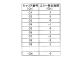
図2には、キャリア番号C1〜CNに対する変調方式の割当の一例が表形式で示されている。図2に示す例ではキャリア番号C1は、当該キャリアが使用されていないことを示すため「0」が記載されている。
In the
FIG. 2 shows an example of assignment of modulation schemes for the carrier numbers C1 to CN in a table format. In the example shown in FIG. 2, “0” is written in the carrier number C1 to indicate that the carrier is not used.
各キャリアについて指定されるキャリア変調方式を示すデータ(設定値)は、本OFDM信号送受信システムで実施可能な複数のキャリア変調方式のうちいずれかを示す値とされる。また、上記設定値の初期値は、本OFDM信号送受信システムで実施可能なキャリア変調方式のうち、変調多値数が最も多いキャリア変調方式を示す値とし、例えば、1024QAMを示すものとする。 Data (setting value) indicating a carrier modulation scheme designated for each carrier is a value indicating one of a plurality of carrier modulation schemes that can be implemented in the OFDM signal transmission / reception system. The initial value of the set value is a value indicating the carrier modulation scheme having the largest number of modulation multi-values among the carrier modulation schemes that can be implemented in the OFDM signal transmission / reception system, for example, 1024QAM.
各キャリアの変調方式は、全キャリアによる1シンボル当たりのデータ伝送量が所望の値になるように決定される。キャリア割当情報Scaにより、全キャリアで伝送される情報量が制御される。
キャリア割当情報Scaはその内容が、キャリア制御器104により、受信状態情報Srsに含まれるエラーフラグSef及び制御対象キャリア番号Scnに基づいて定められ、或いは変更(再設定)される。
The modulation scheme of each carrier is determined so that the data transmission amount per symbol by all carriers becomes a desired value. The amount of information transmitted on all carriers is controlled by the carrier allocation information Sca.
The content of the carrier allocation information Sca is determined or changed (reset) by the
キャリア割当情報Scaは、画像データの送信のために利用可能なキャリアの数に等しい数の要素で構成される配列とされ、配列の先頭から順に利用可能なキャリアにそれぞれ適用するキャリア変調方式を示すデータ(設定値)が並べられる。即ち、キャリア制御器104から出力されるキャリア割当情報Scaは、図2のキャリア番号を含まず、変調方式を示すデータをキャリア番号順に並べたもの(配列)で構成される。
The carrier allocation information Sca is an array composed of a number of elements equal to the number of carriers that can be used for transmission of image data, and indicates a carrier modulation scheme that is applied to each carrier that can be used in order from the top of the array. Data (setting values) are arranged. In other words, the carrier allocation information Sca output from the
各キャリアに適用するキャリア変調方式は、受信状態情報Srsに含まれるエラーフラグSefと前回のキャリア変調方式に基づき決定される。
例えば、受信状態情報Srsに含まれるエラーフラグSefが、伝送エラーが頻発していることを示す「1」であった場合、1シンボル当たりの伝送情報量が前回適用した変調方式よりも少ない(変調多値数がより少ない)キャリア変調方式を、そのキャリアに適用される新たな変調方式として再設定し、該変調方式を表す値(設定値)を、キャリア割当情報Scaの配列の要素とする。
The carrier modulation scheme applied to each carrier is determined based on the error flag Sef included in the reception state information Srs and the previous carrier modulation scheme.
For example, when the error flag Sef included in the reception status information Srs is “1” indicating that transmission errors frequently occur, the amount of transmission information per symbol is smaller than the modulation scheme applied last time (modulation). The carrier modulation scheme having a smaller multi-value number is reset as a new modulation scheme applied to the carrier, and a value (setting value) representing the modulation scheme is used as an element of the array of the carrier allocation information Sca.
逆に、受信状態情報Srsに含まれるエラーフラグSefが伝送エラーの頻発状況が終息乃至解消したことを示す「0」であった場合、1シンボル当たりの伝送情報量が前回適用したキャリア変調方式よりも多い(変調多値数がより多い)キャリア変調方式を、そのキャリアに適用される新たな変調方式として再設定し、該変調方式を表す値(設定値)を、キャリア割当情報Scaの配列の要素とする。 On the other hand, when the error flag Sef included in the reception status information Srs is “0” indicating that the frequent occurrence of transmission errors has ended or disappeared, the transmission information amount per symbol is greater than the carrier modulation scheme applied last time. Is reset as a new modulation scheme applied to the carrier, and a value (setting value) representing the modulation scheme is set in the array of the carrier allocation information Sca. Element.
このようにして、キャリア制御器104は、画像データの送信に用いられるキャリアに対してキャリア変調方式を決定し、決定したキャリア変調方式を含むキャリア割当情報Scaを出力するとともに、各キャリアについて決定したキャリア変調方式に基づいて、1シンボルで全キャリアにより伝送可能な情報量を算出し、伝送データ量見積値Agiとして、エンコード制御器105に出力する。キャリア制御器104はまた、受信器201の受信状態評価器231から送信される、受信状態情報Srsに含まれる画質推定値Sqpをエンコード制御器105に出力する。
In this way, the
エンコード制御器105は、キャリア制御器104を介して供給される画質推定値Sqp(受信器201から伝送された、受信状態情報Srsに含まれる画質評価結果)と、キャリア制御器104から出力された伝送データ量見積値Agi(1シンボルで伝送可能な情報量)を入力として、エンコーダ102がエンコードする際に用いるべき符号化パラメータSqsを決定し、決定した符号化パラメータSqsを示すデータを、エンコーダ102へ出力する。
The
ここで、符号化パラメータSqsはエンコードによる情報圧縮率を示すものとする。符号化パラメータSqsの値が大きいほど圧縮率が高い。圧縮率は、圧縮の程度を表すものであり、例えば
圧縮率=(圧縮前の情報量−圧縮後の情報量)/圧縮前の情報量
で定義される。
Here, the encoding parameter Sqs indicates an information compression rate by encoding. The larger the value of the encoding parameter Sqs, the higher the compression rate. The compression rate represents the degree of compression, and is defined by, for example, compression rate = (information amount before compression−information amount after compression) / information amount before compression.
符号化がJPEGに従って行われる場合、符号化パラメータSqsは量子化スケールQSとし、符号化がH.264に従って行われる場合、符号化パラメータSqsは量子化パラメータqPとする。 When encoding is performed according to JPEG, the encoding parameter Sqs is the quantization scale QS and the encoding is H.264. When performed according to H.264, the encoding parameter Sqs is the quantization parameter qP.
エンコード制御器105は、受信されたビットストリームSsbに基づいて表示される画像の画質推定値Sqp(受信器201からの画質評価結果Sqpで表される)が所定の基準値(画質基準値)Qb以上となるよう、符号化パラメータSqsを決定する。
The
例えば、エンコード制御器105は、受信状態情報Srsに含まれる画質評価結果Sqpが基準値Qb以上のときは、キャリア制御器104で算出された伝送データ量見積値Agi(1シンボルで伝送可能な情報量)に基づき、符号化パラメータSqsを算出する。より具体的には、画質推定値Sqpが基準値Qb以上で、かつ伝送データ量見積値Agiが増加した場合には、符号化パラメータSqsを小さくし、画質推定値Sqpが基準値Qb以上で、かつ伝送データ量見積値Agiが減少した場合には、符号化パラメータSqsを変更しない(現状維持とする)。
一方、画質評価結果Sqpが基準値Qbよりも低いときは、符号化パラメータSqsをより大きな値にする。
For example, when the image quality evaluation result Sqp included in the reception state information Srs is greater than or equal to the reference value Qb, the
On the other hand, when the image quality evaluation result Sqp is lower than the reference value Qb, the encoding parameter Sqs is set to a larger value.
符号化パラメータSqsを小さくする場合には、例えば、前回の値に対して1よりも小さい所定の値、例えば0.8を掛ける。一方、符号化パラメータSqsを大きくする場合には、例えば前回の値に対して1よりも大きい所定の値、例えば1.2を掛ける。 In order to reduce the encoding parameter Sqs, for example, the previous value is multiplied by a predetermined value smaller than 1, for example, 0.8. On the other hand, when the encoding parameter Sqs is increased, for example, the previous value is multiplied by a predetermined value greater than 1, for example 1.2.
符号化パラメータSqsの初期値としては、理想的な伝送路(伝送エラーが全く発生しない)の場合における、本OFDM信号送受信システムで伝送し得る最大のデータ量を生じさせる値が与えられる。 As an initial value of the encoding parameter Sqs, a value that gives the maximum amount of data that can be transmitted by the OFDM signal transmission / reception system in an ideal transmission path (no transmission error occurs) is given.
上記の符号化パラメータの決定方法は、下記の式(1)で表される。

上記の符号化パラメータの決定方法は、画質推定値Sqpを低下させる原因としてエンコードによる符号化ノイズの影響よりも伝送エラーによる画像ノイズの影響が大きい場合を想定している。
画質推定値Sqpが基準値Qbよりも低い場合には、受信器201への伝送過程で伝送エラーが発生したことにより、復調及びデコードしたデータに画像ノイズが多く発生したためと考えられる。そこで、符号化パラメータSqsを高く、即ち圧縮率を高くすることで伝送されるデータ量を低下させている。一方、各キャリアで伝送するデータ量はキャリア制御器104によって制御されており、伝送エラーが頻発しているキャリアで伝送されるデータ量を少なくすることで、そのキャリアにおける伝送エラーを少なくことができ、従って、伝送エラーによる画質劣化を防ぐことができる。
The encoding parameter determination method assumes that the influence of image noise due to a transmission error is larger than the influence of encoding noise due to encoding as a cause of reducing the image quality estimation value Sqp.
When the estimated image quality Sqp is lower than the reference value Qb, it is considered that a large amount of image noise is generated in the demodulated and decoded data due to a transmission error occurring in the transmission process to the
なお、符号化パラメータSqsの決定に当たっては、符号化パラメータSqsとビットレート、符号化パラメータSqsと画質の関係をそれぞれ示す数値モデルを用いて、それぞれの関係から符号化後のデータ量が伝送データ量見積値Agi(設定された変調方式で伝送可能なデータ量))以下となり、かつ画質推定値Sqpが基準値Qb以上となる最適な符号化パラメータSqsを算出するようにしても良い。この場合、数値モデルを予め用意する必要があるが、符号化パラメータSqsとビットレートと画質の関係を用いて符号化パラメータSqsを算出するため、受信状態に応じて画像データIdに最適なエンコードを施すことができる。 In determining the encoding parameter Sqs, a numerical model indicating the relationship between the encoding parameter Sqs and the bit rate, and the relationship between the encoding parameter Sqs and the image quality is used. It is also possible to calculate an optimal encoding parameter Sqs that is equal to or less than the estimated value Agi (data amount that can be transmitted by the set modulation method) and that the image quality estimated value Sqp is equal to or greater than the reference value Qb. In this case, it is necessary to prepare a numerical model in advance. However, since the encoding parameter Sqs is calculated using the relationship between the encoding parameter Sqs, the bit rate, and the image quality, optimal encoding is performed on the image data Id according to the reception state. Can be applied.
次に、受信器201における受信状態情報Srsの生成についてさらに詳しく説明する。
上記のようにOFDM復調器202は、OFDM信号Smに対するOFDM復調に際し、誤り訂正処理を行って、検出された誤りの発生及び位置を示す誤り検出情報Sebを生成し、伝送路評価器211へ出力する。誤りの位置を示す情報から、誤りビット並びに該誤りビットを含むデータ部分を特定することができる。
Next, generation of the reception state information Srs in the
As described above, the
誤り訂正復号を施した際に誤りが検出されない場合、誤り検出情報Sebとしては無効データを表す信号を生成し、出力する。
誤りが検出されない場合、誤り検出情報Sebは出力しなくても良いが、誤りを検出した場合、誤り検出情報Sebなどの誤りの発生状況を示すデータは決められた周期で(決められた周期的なタイミングでのみ)出力するのが好ましい。そうすることで、送信器101では、周期的なタイミングでのみ、伝送エラーに対処するために処理をすれば良くなるからである。
If no error is detected when error correction decoding is performed, a signal representing invalid data is generated and output as error detection information Seb.
If no error is detected, the error detection information Seb may not be output. However, when an error is detected, data indicating the error occurrence status such as the error detection information Seb is determined at a predetermined period (determined periodic It is preferable to output only at a proper timing. By doing so, the
伝送路評価器211は、OFDM復調器202から出力される、受信データの各フレーム毎の誤り検出情報Sebに基づき、伝送エラーが頻発しているキャリア、及び伝送エラーの頻発状況が解消したキャリアを特定する番号(制御対象キャリア番号)Scnと、該キャリアについて伝送エラーが頻発していること、或いは伝送エラーの頻発状況が解消したことを示すエラーフラグSefを生成して出力する。
Based on the error detection information Seb for each frame of the received data, which is output from the
伝送路評価器211は、例えば図3に示すように、誤り検出キャリア特定器212と、キャリア解析器213を備える。
For example, as shown in FIG. 3, the transmission path evaluator 211 includes an error detection
誤り検出キャリア特定器212は、OFDM復調器202からの誤り検出情報Sebに基づき、該情報Sebにより示される誤り位置に対応するビットを含むデータ部分が送信時にOFDM変調器103で変調された際に、当該データ部分が割り当てられた(当該データ部分により変調された)キャリアを特定し、そのキャリアを示す番号を誤り検出キャリア番号Senとしてキャリア解析器213へ出力する。
Based on the error detection information Seb from the
OFDM変調器103がインターリーバを備えたものである場合、誤り検出キャリア特定器212は、OFDM変調器103と同じインターリーバによって、該情報Sebにより示される誤り位置に対応するビットの、ビットストリームSmにおける位置(順位)を再現する。これにより、当該ビットを含むデータ部分が伝送されたキャリアを特定することができる。
When the
誤り検出情報Sebが無効データの場合、誤り検出キャリア特定器212は無効なデータを表す信号を誤り検出キャリア番号Senとして生成し、出力する。
When the error detection information Seb is invalid data, the error detection
キャリア解析器213は、誤り検出キャリア特定器212から出力される誤り検出キャリア番号Senを入力として、所定の期間毎に、該所定の期間にわたり誤りを検出した回数や連続性などをキャリア毎に集計し、解析する。上記の所定の期間(エラー検出周期)は例えば送信される画像データの1フレーム、或いはその整数倍に相当する期間とされる。
The
キャリアごとの集計は、画像データの送信に利用可能な全てのキャリアの各々において所定の期間中にエラーが発生したか否かを判定し、判定結果に応じて対応するエラー発生指標EI1〜EINの値に対する制御を行う。なお、本OFDM信号送受信システムで利用可能なキャリアのうち、画像データの送信に用いられていないキャリアについてはエラーの集計が行われず、従ってエラー発生指標EInの値は「0」に維持にされる。 The aggregation for each carrier is performed by determining whether or not an error has occurred in each of all the carriers that can be used for transmitting image data during a predetermined period, and corresponding error occurrence indices EI1 to EIN are determined according to the determination result. Control over the value. Of the carriers that can be used in the present OFDM signal transmission / reception system, errors are not counted for carriers that are not used for image data transmission, and therefore the value of the error occurrence index EIn is maintained at “0”. .
上記のエラー発生指標EI1〜EINの値の一例を、キャリア番号に対応付けて表形式で表すと図4に示す如くとなる。各指標EIn(n=1〜Nのいずれか)が取り得る数値は、1以上、0、−1以下の3種類に分けられ、1以上のときはエラーが連続的に発生した回数を示し、0のときはエラーが発生していないことを示し、−1以下のときはエラーが発生していたが解消し、その後エラーが発生しないフレームが連続した回数を示す。 An example of the values of the above error occurrence indices EI1 to EIN is shown in FIG. 4 in a table format in association with the carrier number. The numerical value that each index EIn (any of n = 1 to N) can take is divided into three types of 1 or more, 0, or −1, and when it is 1 or more, it indicates the number of times an error has occurred continuously, When it is 0, it indicates that no error has occurred, and when it is −1 or less, it indicates the number of consecutive frames in which an error has occurred but has been eliminated and thereafter no error has occurred.
OFDM復調器202から出力される誤り検出情報Sebが無効データでなく(誤りが検出されたことを示し)、誤り検出キャリア特定器212により誤りが検出されたキャリアを特定するキャリア番号Senが出力された場合、キャリア解析器213は、当該キャリア番号Senで特定されるキャリアについてのエラー発生指標EInの値に応じて以下のような処理を行う。
(A1) 指標EInの値が「0」以上であれば、当該指標EInの値を1だけインクリメントする。
(A2) 指標EInの値が「−1」以下であれば、「1」にセットする。
The error detection information Seb output from the
(A1) If the value of the index EIn is “0” or more, the value of the index EIn is incremented by 1.
(A2) If the value of the index EIn is “−1” or less, it is set to “1”.
誤りが検出されなかったキャリア、即ちキャリア解析器213から出力される誤り検出キャリア番号Senで特定されるキャリア以外のキャリアについては、当該キャリアについてのエラー発生指標EInの値に応じて、以下のような処理を行う。
(B1) 指標EInの値が、「0」であれば「0」のままとする。
(B2) 指標EInの値が、「1」以上の場合、「−1」にセットする。
(B3) 指標EInの値が、「−1」以下の場合、指標EInの値を1だけデクリメントする。
For carriers in which no error has been detected, that is, carriers other than the carrier identified by the error detection carrier number Sen output from the
(B1) If the value of the index EIn is “0”, it remains “0”.
(B2) When the value of the index EIn is “1” or more, it is set to “−1”.
(B3) When the value of the index EIn is “−1” or less, the value of the index EIn is decremented by 1.
キャリア解析器213では、各キャリアについてのエラー発生指標EInの値が正の値である第1の所定値Eat、例えば5以上になると、値が「1」であるエラーフラグSefを生成し、負の値である第2の所定値Ebt、例えば−5以下になると値が「0」であるエラーフラグSefを生成する。
The
エラーフラグSefの値が「1」であることは、対応するキャリアにおいてエラーが頻発しており、変調多値数がより少ない変調方式への変更が必要であることを示す。
エラーフラグSefの値が「0」であることは、対応するキャリアにおいてエラーの頻発状況が解消したので、変調多値数がより多い変調方式への変更を行っても良いことを示す。
エラーフラグSefと制御対象キャリア番号Scnは、互いに関連付けて受信状態評価器231に供給される。
The value of the error flag Sef being “1” indicates that errors frequently occur in the corresponding carrier, and it is necessary to change to a modulation scheme with a smaller number of modulation multilevels.
The value of the error flag Sef being “0” indicates that the frequent occurrence of errors has been resolved in the corresponding carrier, so that it is possible to change to a modulation scheme with a larger number of modulation multilevels.
The error flag Sef and the control target carrier number Scn are supplied to the
エラー発生指標EInの値が第1の閾値Hthよりも小さく、第2の閾値Lthよりも大きいキャリアについては該当するキャリア番号を受信状態評価器231に出力しない。
The carrier number corresponding to the carrier having the error occurrence index EIn smaller than the first threshold Hth and larger than the second threshold Lth is not output to the
受信状態評価器231は、キャリア解析器213から出力されるエラーフラグSefと制御対象キャリア番号Scnと、画質評価器221から出力される画質推定値Sqpをまとめて受信状態情報Srsとして生成し、送信器101へ出力する。
The
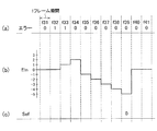
図5(a)〜(c)、及び図6(a)〜(c)は、上記(A1)、(A2)、(B1)〜(B3)の規則に従うエラー発生指標EInの変化及びこれに伴う、値が「1」又は値が「0」のエラーフラグSefの発生の例を示す。図5(a)〜(c)及び図6(a)〜(c)においては1フレーム期間毎にエラーの発生の有無をチェックしており、図5(a)及び図6(a)において、エラーが発生したフレーム期間は「1」で、エラーが発生しなかったフレーム期間は「0」で示されている。図5(a)及び図6(a)に示される各フレーム期間におけるエラーの発生の有無に応じたエラー発生指標EInの変化は次のフレーム期間に生じる。 FIGS. 5A to 5C and FIGS. 6A to 6C show changes in the error occurrence index EIn according to the rules (A1), (A2), and (B1) to (B3), and An example of the generation of the error flag Sef having a value “1” or a value “0” is shown. 5 (a) to (c) and FIGS. 6 (a) to (c), the occurrence of an error is checked every frame period. In FIGS. 5 (a) and 6 (a), A frame period in which an error has occurred is indicated by “1”, and a frame period in which no error has occurred is indicated by “0”. A change in the error occurrence index EIn depending on whether or not an error has occurred in each frame period shown in FIGS. 5A and 6A occurs in the next frame period.
図5(b)に示す例では、フレーム期間f15からフレーム期間f19まで5フレーム期間にわたり連続してエラーの発生が検出された結果、次のフレーム期間f20においてエラー発生指標EInの値が「5」に達し、そのために、図5(c)に示すように、フレーム期間f20において、値が「1」のエラーフラグSefが発生されている。また、フレーム期間f19以降もエラーが発生しているために、エラー発生指標EInの値は、「6」、「7」と増加を続け、値が「1」のエラーフラグSefが、引き続き発生されている。
値が「1」のエラーフラグSefは、対応する制御対象キャリア番号Scnとともに送信器101に送信される。
エラー発生指標EInの値には、所定の上限値を設けても良い。上限値は、第1の閾値Hthと、各キャリアに初期値として設定するキャリア変調方式以外に選択可能なキャリア変調方式の数とを加算したものとする。あるキャリアにエラーの発生が続く場合、エラー発生指標EInは上限値に達した時点でインクリメントをやめて、上限値を維持することとする。
In the example shown in FIG. 5B, as a result of detecting the occurrence of errors continuously over five frame periods from the frame period f15 to the frame period f19, the value of the error occurrence index EIn is “5” in the next frame period f20. Therefore, as shown in FIG. 5C, the error flag Sef having the value “1” is generated in the frame period f20. Further, since an error has occurred after the frame period f19, the value of the error occurrence index EIn continues to increase to “6” and “7”, and the error flag Sef having the value “1” is continuously generated. ing.
The error flag Sef having the value “1” is transmitted to the
A predetermined upper limit value may be provided for the value of the error occurrence index EIn. The upper limit value is obtained by adding the first threshold value Hth and the number of selectable carrier modulation schemes other than the carrier modulation scheme set as the initial value for each carrier. When an error continues to occur in a certain carrier, the error occurrence index EIn stops incrementing when it reaches the upper limit value and maintains the upper limit value.
図6(b)に示す例では、フレーム期間f32、f33でエラーの発生が検出されたが、フレーム期間f33に続くフレーム期間f34からf38まで5フレーム期間にわたり、エラーの発生が検出されなかったため、フレーム期間f35で「−1」となり、フレーム期間f39において、エラー発生指標EInの値が「−5」に達し、そのため、図6(c)に示すように、フレーム期間f39において、値が「0」のエラーフラグSefが発生され、対応する制御対象キャリア番号Scnとともに送信器101に送信される。
値が「0」のエラーフラグSefが送信器101に送信されると、次のフレーム期間f40では、エラー発生指標EInが「0」にリセットされる。
In the example shown in FIG. 6B, the occurrence of an error was detected in the frame periods f32 and f33, but the occurrence of the error was not detected over 5 frame periods from the frame period f34 to f38 following the frame period f33. It becomes “−1” in the frame period f35, and the value of the error occurrence index EIn reaches “−5” in the frame period f39. Therefore, as shown in FIG. 6C, the value becomes “0” in the frame period f39. Error flag Sef is generated and transmitted to the
When the error flag Sef having the value “0” is transmitted to the
伝送路評価器211、或いは受信状態評価器231から出力されるエラーフラグSefと制御対象キャリア番号Scnを関連付けたデータは、図4に示す表形式にする必要はなく、制御対象キャリア番号Scnを順に並べた配列の形式であっても良い。
The data relating the error flag Sef and the control target carrier number Scn output from the transmission path evaluator 211 or the
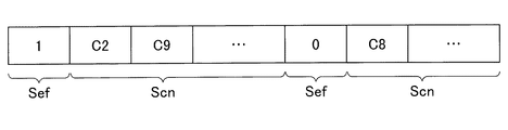
例えば、エラーフラグSefの値が同じ制御対象キャリア番号Scnが複数個ある場合には、一つのエラーフラグSefの値に対して、エラーフラグSefの値が同じ制御対象キャリア番号Scnがまとめて送信される。例えば、図7に示されるように、先頭にフラグSefの値が「1」であることを示すデータが位置し、その後に該エラーフラグSefの値が「1」である、1又は2以上の制御対象キャリア番号Scn(即ち伝送エラーが頻発していることが検出されているキャリアの番号)を並べた配列と、先頭にフラグSefの値が「0」であることを示すデータが位置し、その後に該エラーフラグSefの値が「0」である、1又は2以上の制御対象キャリア番号Scn(即ち伝送エラーの頻発状況が解消したキャリアの番号)を並べた配列とが出力される。 For example, when there are a plurality of control target carrier numbers Scn having the same value of the error flag Sef, the control target carrier numbers Scn having the same value of the error flag Sef are collectively transmitted for one error flag Sef value. The For example, as shown in FIG. 7, data indicating that the value of the flag Sef is “1” is positioned at the head, and thereafter, the value of the error flag Sef is “1”. An array in which the control target carrier number Scn (that is, the number of the carrier in which the transmission error is frequently detected) is arranged, and data indicating that the value of the flag Sef is “0” is positioned at the beginning, Thereafter, an array in which one or two or more control target carrier numbers Scn (that is, carrier numbers in which the frequent occurrence of transmission errors have been resolved) in which the value of the error flag Sef is “0” is arranged is output.
送信器101においては、上記のように、受信器201から送信されたエラーフラグSef及び制御対象キャリア番号Scnに基づいて、キャリア割当情報の再設定を行う。
In the
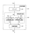
画質評価器221は、上記のように、OFDM復調器202からのビットストリームSrbに基づいて画質を評価し、画質評価結果としての画質推定値Sqp(を示すデータ)を出力する。画質評価器221は、例えば図8に示すように、デコーダ222と、特徴量算出器223と、客観評価器224を備える。
As described above, the
デコーダ222は、OFDM復調器202からのビットストリームSrbを入力として所定のフォーマットにデコードし、デコードにより得られた画像データSidを特徴量算出器223へ出力する。
The
特徴量算出器223は、画像データSidから複数の画像特徴量を算出し、客観評価器224は、特徴量算出器223で算出された画像特徴量から、画質を客観的に評価した画質推定値Sqpを出力する。
The
特徴量算出器223は、フレーム内特徴量算出器223aとフレーム間特徴量算出器223bを構える。
The
フレーム内特徴量算出器223aは、デコーダ222からの画像データSidに基づき、1フレーム毎の画像特徴量であるフレーム内特徴量Ssiを算出する。フレーム内特徴量Ssiとしては、伝送エラーによるノイズを抽出するため、例えば、上記の非特許文献1に記載されている空間的な特徴量SI(Spatial Information)を用いるものとする。
The in-frame
フレーム内特徴量Ssiは1フレーム単位で算出することとしても良く、1フレームを各々複数画素からなるブロックに分割した単位での算出を行っても良い。
フレーム単位で算出する場合には、フレーム内特徴量Ssiは、1個の値を表すデータSsid(d=1)から成る。ブロック単位で算出する場合には、フレーム内特徴量Ssiは、1個又は複数個の値を表すデータSsid(d=1〜D(D≧1))から成る。データSsidは、例えばそれぞれ対応するブロックの特徴量を表すデータから成るものであっても良い。
さらに、それぞれのブロックの特徴量に基づいて得られた、1種類以上の統計値を表すデータから成るものであっても良く、該統計値と、フレーム単位で算出された特徴量との組合せであっても良い。
統計値としては、それぞれのブロックの特徴量の最大値、最小値、平均値が挙げられる。
このように統計値や、統計値とフレーム単位の特徴量との組合せを用いることで、画質判定の精度を上げることができる。
フレーム内特徴量Ssiは、客観評価器224に出力される。
The in-frame feature quantity Ssi may be calculated in units of one frame, or may be calculated in units obtained by dividing one frame into blocks each composed of a plurality of pixels.
In the case of calculation in units of frames, the in-frame feature amount Ssi is composed of data Ssi d (d = 1) representing one value. In the case of calculation in units of blocks, the in-frame feature quantity Ssi is composed of data Ssi d (d = 1 to D (D ≧ 1)) representing one or a plurality of values. Data Ssi d may be, for example, consist of data representing the characteristic quantity of each corresponding block.
Furthermore, it may be composed of data representing one or more kinds of statistical values obtained based on the feature values of each block, and the combination of the statistical values and the feature values calculated in units of frames. There may be.
Examples of the statistical value include the maximum value, the minimum value, and the average value of the feature values of each block.
In this way, the accuracy of image quality determination can be improved by using a statistical value or a combination of a statistical value and a feature quantity in units of frames.
The in-frame feature quantity Ssi is output to the
フレーム内特徴量算出器223aが算出するフレーム単位又はブロック単位のフレーム内特徴量としては、空間的な特徴量SIでなく、画像の特徴を表す他の指標を用いてもよい。
As the intra-frame feature quantity in units of frames or blocks calculated by the intra-frame
フレーム間特徴量算出器223bは、デコーダ222からの各フレームの画像データSidを含めた時間的に前後する2フレーム以上の画像データ(各フレームの画像データSidと、その前及び/又は後の1以上のフレームの画像データ)Sidに基づき、複数フレームでの画像特徴量であるフレーム間特徴量Stiを算出する。各フレーム画像データSidとその後のフレームを使う場合には、デコーダ222から、「後のフレーム」のデータが出力された後に、当該フレームの特徴量の算出を行う。そのためのフレームバッファ(図示しない)がフレーム間特徴量算出部223bに設けられている。
The inter-frame
算出するフレーム間特徴量Stieは、映像の動きのなめらかさを測る指標として用いられるとともに、伝送エラーにより重畳されるブロック状のノイズを抽出するために利用されるものであり、例えば、上記の非特許文献1に記載されている時間的な特徴量TI(Temporal Information)を用いることができる。
Inter-frame feature value Sti e to calculate, as well it used as an index for measuring the smoothness in movement of a video, which are used to extract the block-shaped noise superimposed by transmission errors, for example, of the The temporal feature amount TI (Temporal Information) described in
フレーム間特徴量Stiは1フレーム単位で算出することとしても良く、1フレームを各々複数画素からなるブロックに分割した単位での算出を行っても良い。
フレーム単位で算出する場合には、フレーム間特徴量Stiは、1個の値を表すデータStie(e=1)から成る。ブロック単位で算出する場合には、フレーム間特徴量Stiは、1個又は複数個の値を表すデータStie(e=1〜E(E≧1))から成る。データStieは、例えばそれぞれ対応するブロックの特徴量を表すデータから成るものであっても良い。
さらに、それぞれのブロックの特徴量に基づいて得られた、1種類以上の統計値を表すデータから成るものであっても良く、該統計値と、フレーム単位で算出された特徴量との組合せであっても良い。
統計値としては、それぞれのブロックの特徴量の最大値、最小値、平均値が挙げられる。
このように統計値や、統計値とフレーム単位の特徴量との組合せを用いることで、画質判定の精度を上げることができる。
フレーム間特徴量Stiは、客観評価器224に出力される。
The inter-frame feature quantity Sti may be calculated in units of one frame, or may be calculated in units obtained by dividing one frame into blocks each composed of a plurality of pixels.
When the calculation is performed in units of frames, the inter-frame feature value Sti includes data Sti e (e = 1) representing one value. When calculating in block units, the inter-frame feature quantity Sti is composed of data Sti e (e = 1 to E (E ≧ 1)) representing one or a plurality of values. Data Sti e may be, for example, consist of data representing the characteristic quantity of each corresponding block.
Furthermore, it may be composed of data representing one or more kinds of statistical values obtained based on the feature values of each block, and the combination of the statistical values and the feature values calculated in units of frames. There may be.
Examples of the statistical value include the maximum value, the minimum value, and the average value of the feature values of each block.
In this way, the accuracy of image quality determination can be improved by using a statistical value or a combination of a statistical value and a feature quantity in units of frames.
The inter-frame feature quantity Sti is output to the
フレーム間特徴量算出器223bが算出するフレーム単位又はブロック単位のフレーム間特徴量としては、時間的な特徴量TIでなく、複数フレームの画像データから算出される画像の特徴を表す他の指標を用いてもよい。
The interframe feature quantity calculated by the interframe
客観評価器224は、特徴量算出器223から出力されるフレーム内特徴量Ssi及びフレーム間特徴量Stiを基に画質を評価し、その結果として画質推定値Sqpを出力する。
The
客観評価器224は、特徴量算出器223において算出された画像特徴量Ssi及びStiに基づき、画像データSidの品質を客観的に評価し、画質推定値Sqpを生成し出力する。画像データSidの品質は予め主観評価実験により主観的な評価値を測定しても良いが、本実施の形態では、処理の対象ではない複数の静止画像又は映像に対する主観評価実験を行った結果を処理の対象である画像についての客観的な評価に反映させることで、処理の対象である画像についても主観的な評価値との相関が高い客観的な評価値を得ることとしている。
The
画像特徴量Ssi及びStiを入力として、例えば以下の式(2)により画質の判定を行い、主観的な画質を画像特徴量から推定した画質推定値Sqpを導出する。式(2)では、画質推定値Sqpは、フレーム内特徴量Ssiを構成するF種類(F≧1)種類のフレーム内特徴量Ssif(f=1〜F)と、フレーム間特徴量Stiを構成するG種類(G≧1)のフレーム間特徴量Stig(g=1〜G)の総和により求められる。
なお、各特徴量Ssif及びStigに係る係数αf、βg並びに定数Cは、予め実施する、複数の静止画像又は映像に対する主観評価実験により導出されるものであり、これにより画質推定値Sqpは、例えば0から5の値をとる。数αf、βg及び定数Cは、1以上の整数である。このようにして得られる画質推定値Sqpは、値が大きいほど画質が良く、値が小さいほど画質が悪いことを表す。ここで、後述する受信状態評価器231への画質推定値Sqpの出力は1フレーム毎にできるが、複数のフレーム毎でもよい。後者の場合、1フレーム毎に算出された画質推定値Sqpに対して、例えば最大値や最小値、平均値等を用いる。
With the image feature amounts Ssi and Sti as inputs, the image quality is determined by the following equation (2), for example, and an image quality estimated value Sqp in which subjective image quality is estimated from the image feature amounts is derived. In the equation (2), the estimated image quality value Sqp is calculated as F type (F ≧ 1) types of in-frame feature values Ssi f (f = 1 to F) and inter-frame feature values Sti constituting the in-frame feature value Ssi. It is obtained by the sum of the G types (G ≧ 1) of inter-frame feature quantities Sti g (g = 1 to G) to be configured.
Incidentally, the characteristic values Ssi f and Sti coefficient according to g α f, β g and constant C is carried out in advance, which is derived by a subjective evaluation experiment for a plurality of still images or video, thereby the image quality estimation value Sqp takes a value from 0 to 5, for example. The numbers α f and β g and the constant C are integers of 1 or more. The image quality estimation value Sqp obtained in this way indicates that the larger the value, the better the image quality, and the smaller the value, the worse the image quality. Here, the output of the image quality estimation value Sqp to the
例えば、画質推定値が取り得る値の範囲が上記のように、0.0〜0.5となるように評価を行い、基準値Qbを例えば3.5と設定する。この場合、受信された画像データIdにより表示される画像の画質が3.5以上となるよう符号化パラメータSqsを決定する。
なお、画質推定値Sqpの取り得る値の範囲が上記した0.0〜5.0ではなく、より広くなるように評価を行っても良い。例えば0.0〜10.0となるようにすると、より詳細な画質の評価を行うことができ、画質の調整の程度をより精密に制御することが可能となる。
For example, the evaluation is performed such that the range of values that the image quality estimation value can take is 0.0 to 0.5 as described above, and the reference value Qb is set to 3.5, for example. In this case, the encoding parameter Sqs is determined so that the image quality of the image displayed by the received image data Id is 3.5 or more.
Note that the evaluation may be performed so that the range of values that the image quality estimation value Sqp can take is not the above 0.0 to 5.0 but wider. For example, when 0.0 to 10.0 is set, more detailed image quality evaluation can be performed, and the degree of image quality adjustment can be controlled more precisely.
受信状態評価器231は、伝送路評価器211からの、画像データの送信に利用可能なキャリアにおけるエラーの発生状況を示すデータ、即ちエラーフラグSef及び制御対象キャリア番号Scnと、画質評価器221からの画質評価結果としての画質推定値Sqpとを受け、これらをまとめて受信状態情報Srsを生成し、送信器101に送信する。
The
以下、受信器201における伝送のエラーの評価結果に基づく、送信器101における変調方式の変更及び符号化パラメータの再設定の処理についてより具体的に説明する。
Hereinafter, the process of changing the modulation scheme and resetting the encoding parameter in the
送信器101のキャリア制御器104は、受信状態情報Srsに含まれる制御対象キャリア番号Scnで特定されるキャリアに対して、該制御対象キャリア番号Scnに対して設定されているエラーフラグSefの値及び当該キャリアに対して前回適用された変調方式に応じて以下のような処理を行う。
The
エラーフラグSefが「1」の場合は、当該制御対象キャリア番号Scnで特定されるキャリアに対して、前回適用された変調方式に比べ、変調多値数がより少ない、従って1シンボル当たりの伝送情報量がより少ない変調方式を決定する。例えば前回のキャリア変調方式の設定値が64QAMを指定するものであった場合、今回適用するキャリア変調方式は64QAMより伝送情報量が少ない32QAMとする。 When the error flag Sef is “1”, the number of modulation multi-values is smaller for the carrier specified by the control target carrier number Scn than the modulation scheme applied last time, and therefore transmission information per symbol. Determine a modulation scheme with a smaller amount. For example, when the setting value of the previous carrier modulation scheme specifies 64QAM, the carrier modulation scheme applied this time is 32QAM, which has a smaller transmission information amount than 64QAM.
ここで、全てのキャリアにおいて、キャリア変調方式の変更による1シンボル当たりの伝送情報量の減少幅は一律としても良く、エラー発生指標(或いはその他の、エラーが連続して発生した回数を反映した指標)に応じて異なるものとしても良い。 Here, in all carriers, the amount of reduction in the amount of transmission information per symbol by changing the carrier modulation method may be uniform, and an error occurrence index (or other index that reflects the number of times an error has occurred continuously). ) May be different depending on.
減少幅を一律にする場合には、例えば前回適用したキャリア変調方式の次に伝送情報量が少ないキャリア変調方式に決定することとしても良く、こうすることで、キャリア変調方式を変更するために複雑な回路を実装する必要がなくなり、回路規模の削減ができる。このとき、あるキャリアに前回適用したキャリア変調方式が、本OFDM信号送受信システムで実施可能な複数のキャリア変調方式のうち、1シンボル当たりの伝送情報量が最も少ないキャリア変調方式で、かつそのキャリアに対応するエラーフラグSefが「1」である場合、キャリア変調方式は変更しないこととしても良く、そのキャリアを使用せず、代わりに他のキャリアを使用することとしても良い。 In order to make the amount of reduction uniform, for example, it may be determined to be a carrier modulation method with the least amount of transmission information after the carrier modulation method applied last time, and this makes it complicated to change the carrier modulation method. It is not necessary to mount a complicated circuit, and the circuit scale can be reduced. At this time, the carrier modulation scheme previously applied to a carrier is the carrier modulation scheme with the least amount of transmission information per symbol among a plurality of carrier modulation schemes that can be implemented in this OFDM signal transmission / reception system, and the carrier When the corresponding error flag Sef is “1”, the carrier modulation scheme may not be changed, the carrier may not be used, and another carrier may be used instead.
一方、伝送情報量の減少幅を異ならせる場合は、例えばエラー発生指標の値が大きいほど、そのキャリアが1シンボル当たりの伝送情報量の減少幅が大きいキャリア変調方式に決定する。例えば、前回適用したキャリア変調方式が64QAMであり、エラー発生指標EInが所定値Hts(第1の閾値Hthよりも大きな値)以下であれば、上記と同様、32QAMに変更する一方、エラー発生指標EInが上記の所定値Htsよりも大きければ、32QAMよりもさらに変調多値数の少ない16QAMに変更する。この場合、画像データの送信に利用可能な全てのキャリアに対してエラー発生指標を記録しておく必要があるが、これにより伝送エラーが発生しやすいキャリアで伝送するデータに発生する誤りをより少なくできる。 On the other hand, when the amount of decrease in the amount of transmission information is made different, for example, the carrier modulation scheme is determined such that the amount of decrease in the amount of transmission information per symbol is larger as the error occurrence index value is larger. For example, if the carrier modulation scheme applied last time is 64QAM and the error occurrence index EIn is equal to or less than a predetermined value Hts (a value larger than the first threshold value Hth), the error occurrence index is changed to 32QAM as described above. If EIn is larger than the above-mentioned predetermined value Hts, it is changed to 16QAM having a smaller modulation multi-value number than 32QAM. In this case, it is necessary to record an error occurrence index for all the carriers that can be used for transmission of image data, but this reduces errors that occur in data transmitted on carriers that are prone to transmission errors. it can.
伝送エラーの頻発を示す制御対象キャリア番号Scnで特定されるキャリアの中に、伝送エラー発生状況が不安定なものがある場合(例えば、エラーの頻発状態の発生と解消が繰り返される場合)や他のキャリアで十分な伝送量を確保できる場合に、当該キャリアを使用しないよう変更することも可能である。これにより、伝送するデータに誤りが発生する可能性を低くできる。 Among the carriers specified by the control target carrier number Scn indicating the frequent occurrence of transmission errors, there are cases where the transmission error occurrence status is unstable (for example, the occurrence and elimination of frequent error occurrence states are repeated), and others If a sufficient amount of transmission can be secured with this carrier, the carrier can be changed so as not to be used. As a result, the possibility of errors occurring in the data to be transmitted can be reduced.
エラーフラグSefが「0」の場合は、当該制御対象キャリア番号Scnで特定されるキャリアに対して、前回適用された変調方式と比べて、変調多値数がより多い、従って1シンボル当たりの伝送情報量がより多い変調方式を決定する。例えば前回のキャリア変調方式の設定値が64QAMを指定するものであった場合、今回適用するキャリア変調方式は64QAMより伝送情報量が多い128QAMとする。 When the error flag Sef is “0”, the number of modulation multivalues is larger for the carrier specified by the control target carrier number Scn than the previously applied modulation scheme, and therefore transmission per symbol is performed. A modulation scheme with a larger amount of information is determined. For example, when the setting value of the previous carrier modulation scheme specifies 64QAM, the carrier modulation scheme applied this time is 128QAM, which has a larger transmission information amount than 64QAM.
ここで、全てのキャリアにおいて、キャリア変調方式の変更によって1シンボル当たりの伝送情報量の増加幅は一律としても良く、エラー発生指標(或いはその他の、エラー発生の後にエラーが連続して生じなかった回数を反映した指標)に応じて異なるものとしても良い。 Here, in all carriers, the amount of increase in the amount of transmission information per symbol may be uniform by changing the carrier modulation method, and an error occurrence index (or other error does not continuously occur after the occurrence of an error). It may be different depending on the index reflecting the number of times.
増加幅を一律にする場合には、例えば前回適用したキャリア変調方式の次に伝送情報量が多いキャリア変調方式に決定することとしても良く、こうすることで、キャリア変調方式を変更するために複雑な回路を実装する必要がなくなり、回路規模の削減ができる。このとき、あるキャリアに前回適用したキャリア変調方式が、本OFDM信号送受信システムで実施可能な複数のキャリア変調方式のうち、1シンボル当たりの伝送情報量が最も多いキャリア変調方式であり、かつそのキャリアについてのエラーフラグSefが「0」である場合、キャリア変調方式は変更しないこととしても良い。 In order to make the increase range uniform, for example, it may be determined to be a carrier modulation method having the next largest amount of transmission information after the carrier modulation method applied last time, and this makes it difficult to change the carrier modulation method. It is not necessary to mount a complicated circuit, and the circuit scale can be reduced. At this time, the carrier modulation scheme previously applied to a certain carrier is the carrier modulation scheme having the largest amount of transmission information per symbol among a plurality of carrier modulation schemes that can be implemented in this OFDM signal transmission / reception system, and the carrier When the error flag Sef for is “0”, the carrier modulation scheme may not be changed.
一方、伝送情報量の増加幅を異ならせる場合は、例えばエラー発生指標が小さいほど、そのキャリアが1シンボル当たりの伝送情報量の増加幅が大きいキャリア変調方式に決定する。例えば、前回適用したキャリア変調方式が64QAMであり、エラー発生指標EInが所定値Lts(第2の閾値Lthよりも小さな値)以上であれば、上記と同様、128QAMに変更する一方、エラー発生指標EInが上記所定値LTsよりも小さければ、128QAMよりもさらに変調多値数の多い256QAMに変更する。この場合、画像データの送信に利用可能な全てのキャリアに対してエラー発生指標を記録しておく必要があるが、これにより伝送エラーが発生しにくいキャリアで伝送するデータの量をできるだけ多くして、伝送効率を上げることができる。 On the other hand, when the increase amount of the transmission information amount is made different, for example, as the error occurrence index is small, the carrier is determined to be a carrier modulation scheme in which the increase amount of the transmission information amount per symbol is large. For example, if the previously applied carrier modulation scheme is 64QAM and the error occurrence index EIn is equal to or greater than a predetermined value Lts (a value smaller than the second threshold Lth), the error occurrence index is changed to 128QAM as described above. If EIn is smaller than the predetermined value LTs, it is changed to 256QAM having a larger modulation multi-value number than 128QAM. In this case, it is necessary to record an error occurrence index for all the carriers that can be used for transmission of image data, but this makes it possible to increase the amount of data transmitted on a carrier that is unlikely to cause a transmission error as much as possible. , Transmission efficiency can be increased.
各キャリアに適用するキャリア変調方式を決定した後、決定したキャリア変調方式を示すキャリア割当情報Scaを出力するとともに、キャリア制御器104は伝送データ量見積値Agiを算出し、伝送データ量見積値Agiと画質推定値Sqpからなる信号を生成し、エンコード制御器105に出力する。伝送データ量見積値Agiの初期値としては、理想的な伝送路(伝送エラーが全く発生しない伝送路)における、本OFDM信号送受信システムで伝送し得る最大のデータ量を生じさせる値が与えられる。
After determining the carrier modulation method to be applied to each carrier, the
なお、上記の例では、図4乃至図6(c)を参照して説明した方法で生成したエラー発生指標EI1〜EINに基づいて変調方式の変更が必要であるか否かの判断をしているが、本発明はこれに限定されず、要するに、エラーの発生回数などエラーの発生状況を表すデータを変調方式の変更を要求する情報として用いて、この情報に基づいて変調方式の変更を行うこととすれば良い。 In the above example, it is determined whether or not the modulation method needs to be changed based on the error occurrence indices EI1 to EIN generated by the method described with reference to FIGS. 4 to 6C. However, the present invention is not limited to this. In short, the data indicating the error occurrence status such as the number of error occurrences is used as information for requesting the change of the modulation method, and the modulation method is changed based on this information. That's fine.
以上の制御を行う結果、変調方式の変更により、伝送エラーの発生を少なくすることが可能である限り変調方式の変更を行い、変調多値数が最も少ない変調方式においてもなお、伝送エラーが多い場合には、これに伴い画質が劣化するので、符号パラメータをより大きな値に変化させる処理がなされる。
上記のように、伝送エラーの発生状況に基づく各キャリアの変調方式の変更、並びにキャリアの変調方式と画質評価値に基づく符号化パラメータの変更をリアルタイムで行っているので、画質を維持するとともに伝送効率を可能な限り高く保つことができる。
As a result of the above control, the modulation method is changed as long as it is possible to reduce the occurrence of transmission errors by changing the modulation method, and there are still many transmission errors even in the modulation method having the smallest number of modulation multi-values. In this case, since the image quality deteriorates accordingly, processing for changing the code parameter to a larger value is performed.
As described above, the modulation method of each carrier is changed based on the transmission error occurrence status, and the coding parameters are changed based on the carrier modulation method and the image quality evaluation value in real time. Efficiency can be kept as high as possible.
以上のように、エラーフラグSefを変調方式の変更を要求する情報として用いて、各キャリアに適用する変調方式の変更をする代わりに、各キャリアに適用するキャリア変調方式の変更を、受信状態情報Srsに含まれる画質推定値Sqpに応じて行っても良い。この場合、キャリア制御器104には、エンコード制御器105と同じ画質基準値Qbを入力しておく(図1に点線で示す)必要がある。また、画質基準値Qbは、受信された画像データにより表示される画像が有することを要求される最低限の品質に対応する値に設定される。画質推定値Sqp及び画質基準値Qbは、値が大きいほど画質が良いことを表す。
As described above, instead of changing the modulation scheme applied to each carrier using the error flag Sef as information requesting the change of the modulation scheme, the change of the carrier modulation scheme applied to each carrier is changed to the reception state information. You may perform according to the image quality estimated value Sqp contained in Srs. In this case, the
例えば、受信状態情報Srsに含まれる画質推定値Sqpが基準値Qbよりも低い場合には、すべてのキャリアにおいて一斉に、又は順次(例えば所定の順序で)送信するデータ量を減少させるようにキャリア変調方式を変更し、画質推定値Sqpが基準値Qb以上の場合には、すべてのキャリアにおいて一斉に、又は順次(例えば所定の順序で)送信するデータ量を増加させるようにキャリア変調方式を変更することとする。 For example, when the image quality estimation value Sqp included in the reception state information Srs is lower than the reference value Qb, the carrier is set so as to reduce the amount of data to be transmitted all at once or sequentially (for example, in a predetermined order). When the modulation method is changed and the estimated image quality value Sqp is equal to or greater than the reference value Qb, the carrier modulation method is changed so as to increase the amount of data to be transmitted all at once or sequentially (for example, in a predetermined order). I decided to.
この場合、エラーフラグSef及び制御対象キャリア番号Scnに基づく変調方式の変更(再設定)とは独立に、画質推定値Sqpに基づく変調方式の変更を行っても良く、制御対象キャリア番号Scn及びエラーフラグSefと画質推定値Sqpとの組合せに基づいて変調方式の変更を行っても良い。 In this case, the modulation method may be changed based on the estimated image quality value Sqp independently of the change (resetting) of the modulation method based on the error flag Sef and the control target carrier number Scn. The modulation method may be changed based on the combination of the flag Sef and the estimated image quality Sqp.
なお、受信状態情報Srsに含まれる画質推定値Sqpが基準値Qb以上の場合、エラーフラグSefが伝送エラーの頻発状況の解消を示していても、現状維持のため、送信するデータ量を増加させるようキャリア変調方式を変更しないこととしても良い。これにより、受信器201で十分に高い画質が得られている場合は、送信器101でキャリア変調方式を変更するための処理による遅延時間をなくすことができる。
When the image quality estimation value Sqp included in the reception state information Srs is equal to or greater than the reference value Qb, the amount of data to be transmitted is increased in order to maintain the current state even if the error flag Sef indicates the elimination of the frequent occurrence of transmission errors. Thus, the carrier modulation scheme may not be changed. As a result, when the
なおまた、図1の例では、表示器301がデコーダ302を内蔵しているが、図8に示すように、受信器201がデコーダ222を有する場合には、デコーダ302は表示器301に内蔵されていなくても良い。この場合、例えば、受信器201のデコーダ222が出力する画像データSidを画像再生器303へ入力すれば良い。
In the example of FIG. 1, the
実施の形態2.
実施の形態2に係るOFDM送受信システムの全体的構成は、図1に示すのと同じであるが、伝送路評価器211が図9のように構成されている点で異なる。
図9の伝送路評価器211は、図3の伝送路評価器211の構成と比較して、エラー発生周期予測器214を付加的に備える点が異なる。図9において、図3と同じ符号のものは、構成及び作用が実施の形態1と同様であるため、説明を省略する。
The overall configuration of the OFDM transmission / reception system according to the second embodiment is the same as that shown in FIG. 1, but is different in that the transmission path evaluator 211 is configured as shown in FIG.
The transmission path evaluator 211 of FIG. 9 is different from the configuration of the transmission path evaluator 211 of FIG. 3 in that an error
エラー発生周期予測器214は、キャリア解析器213から出力されるエラーフラグSef及び制御対象キャリア番号Scnから、画像データの送信に利用可能な全てのキャリアの各々において、所定の期間毎に1回以上エラーが発生したか否かを判定し、判定結果を、それぞれの期間に対応付けて記録する。
この場合、各所定の期間に1回以上エラーが検出された場合にのみ、エラーが検出された期間(を代表する)時刻(例えば該期間の開始の時刻)をエラー発生時刻として記録するようにしても良い。
エラー発生時刻を示す情報はキャリアごとに得られるが、この情報も表形式のものでなくても、配列形式のものであっても良い。
The error
In this case, only when an error is detected at least once in each predetermined period, the time (representing the time) in which the error is detected (for example, the start time of the period) is recorded as the error occurrence time. May be.
Information indicating the error occurrence time is obtained for each carrier, but this information may not be in a table format but may be in an array format.
エラー発生周期予測器214は、上記の記録から、各キャリアについてエラーの周期性の有無を判定し、エラーの発生に周期性がある場合に、その周期性を示す情報(周期性情報)Sceを生成して出力する。この周期性情報には、周期の長さを表す情報と、基準となる時刻(例えば現在時刻)から、次にエラーが発生すると予想されるタイミングまでの時間差を表す情報とが含まれる。
出力された周期情報Sceは、受信状態評価器231により、受信状態情報Srsの一部として送信される。
なお、受信状態情報Srsに周期性情報Sceを送信器101に送信するか否かを、設定により選択可能としても良い。
The error
The output period information Sce is transmitted by the
Note that whether to transmit the periodicity information Sce to the
キャリア制御器104では、周期性情報Sceを用いて、エラーが発生すると予測される時刻及びその前後の時間帯には、当該キャリアを使用しないようキャリア割当情報Scaを再設定する。
The
実施の形態1の構成であると、伝送エラーの発生からキャリア割当情報Scaへの反映までに遅延が生じるが、実施の形態2の構成であると、伝送エラーが生じるタイミングに先立って変調方式の変更(キャリア割当の再設定)を行うので、伝送エラーの発生を未然に防止でき、より安定した伝送を行うことができる。 With the configuration of the first embodiment, a delay occurs from the occurrence of a transmission error until the reflection to the carrier allocation information Sca. However, with the configuration of the second embodiment, the modulation scheme is prior to the timing at which the transmission error occurs. Since the change (reassignment of carrier allocation) is performed, the occurrence of a transmission error can be prevented and more stable transmission can be performed.
周期性情報を得るために、エラーの発生についての観測を連続的に行っても良く、断続的に行っても良い。断続的に行う場合、所定の期間(観測実行周期)毎に観測を行い、各回の観測で周期性情報が得られたら、次に観測を行うまで、得られた周期性情報を利用し続けることとしても良い。観測実行周期は上記のエラー検出周期よりも長い。各回の観測は、周期性の有無の判定、及び周期の長さ及び上記の時間差の算出に必要な情報を得るのに十分な長さとする。上記の観測を連続的に行えば、エラーの発生周期が変化した場合にも、迅速に対応することが出来る点で有利である。 In order to obtain periodicity information, the occurrence of an error may be observed continuously or intermittently. When performing intermittently, observe every predetermined period (observation execution cycle), and once the periodicity information is obtained in each observation, continue to use the obtained periodicity information until the next observation It is also good. The observation execution cycle is longer than the error detection cycle described above. Each observation is made long enough to determine the presence or absence of periodicity and to obtain information necessary for calculating the length of the period and the above time difference. If the above observation is performed continuously, it is advantageous in that it is possible to respond quickly even when the error generation period changes.
なお、受信状態情報Srsに周期性情報Sceを含める代わりに、エラー発生周期予測器214は、伝送エラーが頻発しているキャリアについて予想されるエラーの頻発が予想されるタイミングに先立ち、エラーの頻発が予想されること示すフラグを、該エラーの頻発が予想されるキャリアを示す制御対象キャリア番号Scnとともに、送信器101に送信することとしても良い。
Note that instead of including the periodicity information Sce in the reception status information Srs, the error
この場合、受信器201の受信状態評価器231及び送信器101は、実施の形態1と同様の処理を行うことで、予想されるエラーの頻発に対する対応をすることができる。即ち、送信器101では、エラーの頻発を予想するフラグを、上記の値が「1」のエラーフラグSefの代わりのものとして扱い、変調多値数がより少ない変調方式への変更を行い、エラーの頻発が予想されるタイミングが過ぎたら、元の変調方式に戻す。受信状態評価器231及び送信器101の構成は実施の形態1と同様で良いので、回路規模を拡大することなく、伝送エラーの発生を未然に防止することができる。
In this case, the
例えば、所定の経路を周回するバスや電車などに本発明のシステムを適用した場合、特定の場所で特定の周波数帯に雑音が存在するときは、周期性のある伝送エラーを事前に抑止できる。例えば電車の場合には、パンタグラフからのノイズによる伝送エラーに対して有効な対策となる。 For example, when the system of the present invention is applied to a bus or train that circulates on a predetermined route, when there is noise in a specific frequency band at a specific place, a periodic transmission error can be suppressed in advance. For example, in the case of a train, this is an effective measure against transmission errors caused by noise from the pantograph.
実施の形態3.
実施の形態3に係るOFDM送受信システムの構成を図10に示す。
図10に示されるOFDM送受信システムは、図1の送受信システムと概して同じであるが、図1の受信状態評価器231、キャリア制御器104、及びエンコード制御器105の代わりに、受信状態評価器241、キャリア制御器114及びエンコード制御器115を備える点で異なる。図10で、図1と同じ符号のものは、構成及び作用が実施の形態1と同様であるため、説明を省略する。受信状態評価器241は、図1の受信状態評価器231と同様に、無線信号送信器231aを備えていても良い。
The configuration of the OFDM transmission / reception system according to
The OFDM transmission / reception system shown in FIG. 10 is generally the same as the transmission / reception system of FIG. 1, but instead of the
受信状態評価器241は、図1の受信状態評価器231と異なり、画質推定値Sqpの代わりに画質フラグSrを受信状態情報Srsの一部として出力し、キャリア制御器114は、画質推定値Sqpの代わりに画質フラグSrを含む受信状態情報Srsを受信して、画質推定値Sqpの代わりに画質フラグSrを出力し、エンコード制御器115は、画質推定値Sqpの代わりに画質フラグSrに基づいて符号化パラメータの再設定を行う。
画質フラグSrは、キャリア制御器114又はエンコード制御器115に対して変調方式又は符号化パラメータの再設定が必要か否かを示すものであり、エラーフラグSefと同様に送信の条件の変更を要求する情報として用いられている。
Unlike the
The image quality flag Sr indicates whether or not the
受信状態評価器241は、画質基準値Qbと画質推定値Sqpに基づき画質フラグSrの値を決定する。この画質基準値Qbは、図1のシステムにおいてエンコード制御器105で用いられるものと同様のものである。
例えば、画質推定値Sqpが基準値Qbよりも低ければ、画質フラグSrの値を第1の値、例えば「1」とし、そうでなければ、画質フラグSrの値を第2の値、例えば「0」とする。
受信状態評価器241は、伝送路評価器211からのエラーの発生状況を示すエラーフラグSef及び制御対象キャリア番号Scnと、内部で生成した画質フラグSrをまとめたものを受信状態情報Srsとして、送信器101に送信する。
The
For example, if the estimated image quality value Sqp is lower than the reference value Qb, the value of the image quality flag Sr is set to a first value, for example “1”; otherwise, the value of the image quality flag Sr is set to a second value, for example “ 0 ”.
The
画質フラグSrにより、エンコード制御器115における符号化パラメータSqsの決定のみを制御する場合には、例えば画質フラグSrが「1」のときは、実施の形態1において画質推定値Sqpが基準値Qbよりも低い場合と同様に制御を行い、画質フラグSrが「0」のときは、実施の形態1において画質推定値Sqpが基準値Qb以上の場合と同様に制御を行うこととしても良い。
When only the determination of the encoding parameter Sqs in the
画質フラグSrにより、キャリア制御器114における変調方式の変更を制御する場合には、実施の形態1の変形例で説明したように、画質フラグSrが「1」の場合には、すべてのキャリアにおいて一斉に又は順次(例えば所定の順序で)変調多値数を減少させるように変調方式を変更し、画質フラグSrが「0」の場合には、すべてのキャリアにおいて一斉に又は順次(例えば所定の順序で)変調多値数を増加させるように変調方式を変更しても良い。
この場合、エラーフラグSef及び制御対象キャリア番号Scnに基づく変調方式の変更(再設定)とは独立に、画質フラグSrに基づく変調方式の変更を行っても良く、制御対象キャリア番号Scn及びエラーフラグSefと画質フラグSrとの組合せに基づいて変調方式の変更を行っても良い。
When the change of the modulation method in the
In this case, the modulation method may be changed based on the image quality flag Sr independently of the change (resetting) of the modulation method based on the error flag Sef and the control target carrier number Scn, and the control target carrier number Scn and the error flag may be changed. The modulation method may be changed based on the combination of Sef and the image quality flag Sr.
また、画質フラグSrが「0」であれば、伝送効率の向上のために、キャリア制御器114において、新たなキャリア割当情報Scaの生成(キャリア割当情報Scaの再設定)を行い、画質フラグSrの値が「1」であれば、画質の向上が望まれるため、エンコード制御器115において、新たな符号化パラメータSqsの算出(再計算)を行うことしても良い。
この場合、キャリア制御器114及びエンコード制御器115は、画質フラグSrがどちらかの値を有するときにのみ、キャリア割当情報Scaの再設定又は符号化パラメータSqpの再計算を行えば良く、エラー状況が変化してから、該変化に対応するための処理を行うまでの時間を短くすることができる。
If the image quality flag Sr is “0”, the
In this case, the
画質フラグSrにより、キャリア制御器114及びエンコード制御器115の一方に対してのみ再設定を要求する場合、画質フラグは1ビットで表現できる。
例えば、上記のように、画質フラグSrが「0」の場合はキャリア制御器114に対する再設定の要求を示し、画質フラグSrが「1」の場合はエンコード制御器115に対する再設定の要求を示すこととしても良い。
When resetting is requested only to one of the
For example, as described above, when the image quality flag Sr is “0”, it indicates a reset request to the
キャリア制御器114は、画質フラグSrがキャリア制御器104に対する再設定を要求する値のものである場合、受信状態情報Srsに含まれるエラーフラグSefと、制御対象キャリア番号Scnから算出可能である各キャリアの伝送可能な情報量に基づき、各キャリアの変調方式を決定し、キャリア割当情報Scaを生成する。各キャリアに適用するキャリア変調方式は、変調多値数が前回適用した変調方式の変調多値数以上となるよう決定する必要がある。キャリア変調方式を決定した後、伝送データ量見積値Agiを算出し、受信状態情報Srsに含まれる画質フラグSrと、伝送データ量見積値Agiをエンコード制御器115へ出力する。
When the image quality flag Sr has a value that requires resetting the
エンコード制御器115は、キャリア制御器114からの画質フラグSrと伝送データ量見積値Agiに基づき、符号化パラメータSqsを一意に決定できる。エンコード制御器115における符号化パラメータSqsの決定の例を式(3)に示す。式(3)中のSqn−1及びSqsは、値が小さいほど圧縮率が低いことを表す。
The
受信状態情報Srsとしてキャリア制御器114又はエンコード制御器115のどちらか一方に対する再設定の要求であることを明確に示すものを用いれば、送信器101は受信状態情報Srsを解析するための計算コストを削減でき、送信器101は受信状態情報Srsを受信してからキャリア制御器114及びエンコード制御器115に適用させるまでの遅延時間を小さくできる。
If the reception status information Srs clearly indicates that it is a reset request for either the
なお、キャリア制御器114及びエンコード制御器115のどちらにおいても再設定を行う場合は、画質フラグSrを2ビットで構成してもよい。画質フラグSrは、画質基準値Qbと画質推定値Sqpを比較するだけで一意に決定できるため、画質フラグSrの算出は簡単に短時間で行うことができる。
When resetting is performed in both the
以上、画質フラグSrを送信条件の変更を要求する情報として用いて、キャリア制御器114における変調方式の変更及び/又はエンコード制御器115における符号化パラメータの変更を行う構成について説明したが、要するに受信器201の受信状態評価器241が各キャリアにおけるエラーの発生状況を示すデータSef、Scnと画質評価結果Sqpに基づいて送信器101における送信の条件(変調方式、符号化パラメータ)の変更を要求する情報を生成し、該情報を受信器201から送信器101に送信し、送信器101ではこの情報に基づいてキャリア制御器114における変調方式の変更、及び/又はエンコード制御器115における符号化パラメータの変更を行う構成とすれば良い。
As described above, the configuration for changing the modulation scheme in the
101 送信器、 102 エンコーダ、 103 OFDM変調器、 104 キャリア制御器、 105 エンコード制御器、 114 キャリア制御器、 115 エンコード制御器、 201 受信器、 202 OFDM復調器、 211 伝送路評価器、 212 誤り検出キャリア特定器、 213 キャリア解析器、 214 エラー発生周期予測器、 221 画質評価器、 222 デコーダ、 223 特徴量算出器、 223a フレーム内特徴量算出器、 223b フレーム間特徴量算出器、 224 客観評価器、 231 受信状態評価器、 241 受信状態評価器、 301 表示器、 302 デコーダ、 303 画像再生器。
101 transmitter, 102 encoder, 103 OFDM modulator, 104 carrier controller, 105 encoding controller, 114 carrier controller, 115 encoding controller, 201 receiver, 202 OFDM demodulator, 211 transmission path evaluator, 212 error detection Carrier identifier, 213 carrier analyzer, 214 error generation period predictor, 221 image quality evaluator, 222 decoder, 223 feature quantity calculator, 223a intra-frame feature quantity calculator, 223b inter-frame feature quantity calculator, 224
Claims (10)
前記送信器は、
前記画像データを符号化パラメータに基づき情報圧縮したビットストリームを生成するエンコーダと、
前記ビットストリームに誤り訂正符号化を行った上で、該ビットストリームを複数のデータ部分に分割して、該分割により得られたそれぞれのデータ部分で異なるキャリアを、それぞれのキャリア変調方式により変調することで、OFDM変調信号を生成するOFDM変調器と、
受信状態情報に基づいて、前記キャリア変調方式を決定し、決定されたキャリア変調方式を示す情報を出力するキャリア制御器と、
前記受信状態情報に含まれる画質評価結果から、前記符号化パラメータを決定し、決定した符号化パラメータを示す情報を出力するエンコード制御器とを備え、
前記受信器は、
前記送信器から受信した前記OFDM信号を復調し、ビットストリームを生成するとともに、前記OFDM信号に対して誤り訂正処理を行い、該誤り訂正処理によって検出された誤り位置を示す誤り検出情報を出力するOFDM復調器と、
前記誤り検出情報から、前記画像データの送信に利用可能なキャリアの各々におけるエラーの発生状況を表すデータを生成し出力する伝送路評価器と、
前記OFDM復調器からの前記ビットストリームに基づいて画質を評価し、画質評価結果を表すデータを出力する画質評価器と、
前記伝送路評価器からの前記エラーの発生状況を表すデータと前記画質評価器からの前記画質評価結果を表すデータとを含む前記受信状態情報を生成し、前記送信器へ出力する受信状態評価器とを備える
ことを特徴とするOFDM信号送受信システム。 An OFDM signal transmission / reception system that modulates image data and transmits it from a transmitter to a receiver,
The transmitter is
An encoder that generates a bitstream in which the image data is information-compressed based on an encoding parameter;
After performing error correction coding on the bitstream, the bitstream is divided into a plurality of data portions, and different carriers are modulated by the respective carrier modulation schemes in the respective data portions obtained by the division. An OFDM modulator for generating an OFDM modulated signal;
A carrier controller that determines the carrier modulation scheme based on reception state information and outputs information indicating the determined carrier modulation scheme;
An encoding controller that determines the encoding parameter from an image quality evaluation result included in the reception state information and outputs information indicating the determined encoding parameter;
The receiver is
Demodulate the OFDM signal received from the transmitter, generate a bitstream, perform error correction processing on the OFDM signal, and output error detection information indicating an error position detected by the error correction processing An OFDM demodulator;
From the error detection information, a transmission path evaluator that generates and outputs data representing an error occurrence state in each of the carriers that can be used for transmission of the image data;
An image quality evaluator that evaluates image quality based on the bitstream from the OFDM demodulator and outputs data representing an image quality evaluation result;
A reception state evaluator that generates the reception state information including data representing the error occurrence state from the transmission path evaluator and data representing the image quality evaluation result from the image quality evaluator, and outputs the reception state information to the transmitter An OFDM signal transmission / reception system comprising:
前記エンコード制御器は、前記画質評価結果が所定の基準値以上のときは、前記キャリア制御器で算出された、前記1シンボルで伝送可能な情報量に基づき、前記符号化パラメータを決定し、
前記エンコード制御器は、前記画質評価結果が前記基準値よりも低いときは、前記符号化パラメータをより大きな値にする
ことを特徴とする請求項1に記載のOFDM信号送受信システム。 The carrier controller can transmit with one symbol by all carriers available for transmission of the image data from a carrier modulation scheme determined for each of the carriers available for transmission of the image data. Calculate the amount of information,
The encoding controller determines the encoding parameter based on the amount of information that can be transmitted by the one symbol, calculated by the carrier controller, when the image quality evaluation result is equal to or greater than a predetermined reference value.
The OFDM signal transmission / reception system according to claim 1, wherein the encoding controller sets the encoding parameter to a larger value when the image quality evaluation result is lower than the reference value.
前記エラーの発生状況を表すデータに基づいて、前記利用可能なキャリアのうちエラーが頻発しているキャリアのキャリア変調方式を、変調多値数がより少ない変調方式に変更する
ことを特徴とする請求項1又は2に記載のOFDM信号送受信システム。 The carrier controller is
The carrier modulation scheme of a carrier in which errors frequently occur among the available carriers is changed to a modulation scheme with a smaller number of modulation multi-values based on data representing the occurrence status of the error. Item 3. The OFDM signal transmission / reception system according to Item 1 or 2.
Priority Applications (1)
| Application Number | Priority Date | Filing Date | Title |
|---|---|---|---|
| JP2012138414A JP2014003512A (en) | 2012-06-20 | 2012-06-20 | Ofdm signal transmission and reception system |
Applications Claiming Priority (1)
| Application Number | Priority Date | Filing Date | Title |
|---|---|---|---|
| JP2012138414A JP2014003512A (en) | 2012-06-20 | 2012-06-20 | Ofdm signal transmission and reception system |
Publications (2)
| Publication Number | Publication Date |
|---|---|
| JP2014003512A true JP2014003512A (en) | 2014-01-09 |
| JP2014003512A5 JP2014003512A5 (en) | 2015-07-02 |
Family
ID=50036288
Family Applications (1)
| Application Number | Title | Priority Date | Filing Date |
|---|---|---|---|
| JP2012138414A Pending JP2014003512A (en) | 2012-06-20 | 2012-06-20 | Ofdm signal transmission and reception system |
Country Status (1)
| Country | Link |
|---|---|
| JP (1) | JP2014003512A (en) |
Cited By (7)
| Publication number | Priority date | Publication date | Assignee | Title |
|---|---|---|---|---|
| WO2017104346A1 (en) * | 2015-12-15 | 2017-06-22 | セイコーエプソン株式会社 | Circuit device, electrooptical device, electronic apparatus, movable body, and error detection method |
| JP2017111219A (en) * | 2015-12-15 | 2017-06-22 | セイコーエプソン株式会社 | Circuit device, electro-optical device, electronic apparatus and movable body |
| JP2018072460A (en) * | 2016-10-26 | 2018-05-10 | セイコーエプソン株式会社 | Circuit device, electro-optic device, electronic apparatus, movable body, and error detection method |
| JP2018074274A (en) * | 2016-10-26 | 2018-05-10 | セイコーエプソン株式会社 | Circuit device, electro-optic device, electronic apparatus, mobile body, and error detection method |
| JP2018140669A (en) * | 2017-02-27 | 2018-09-13 | 株式会社京三製作所 | Information transmission system, transmitter and on-board device |
| JP2019501566A (en) * | 2016-03-11 | 2019-01-17 | ▲騰▼▲訊▼科技(深▲セン▼)有限公司 | Video data redundancy control method and apparatus |
| WO2023195079A1 (en) * | 2022-04-05 | 2023-10-12 | 株式会社Nttドコモ | Terminal, wireless communication method, and base station |
Citations (8)
| Publication number | Priority date | Publication date | Assignee | Title |
|---|---|---|---|---|
| JP2001148682A (en) * | 1999-11-22 | 2001-05-29 | Victor Co Of Japan Ltd | Multi-carrier transmitter and receiver and data transmitting method for the transmitter and receiver |
| JP2004064171A (en) * | 2002-07-25 | 2004-02-26 | Toshiba Corp | Information processor |
| JP2004523945A (en) * | 2000-12-22 | 2004-08-05 | ノキア インコーポレイテッド | Error reduction method and apparatus in quadrature modulation system |
| JP2005020076A (en) * | 2003-06-23 | 2005-01-20 | Toshiba Corp | Communication method, transmission apparatus, and reception apparatus |
| JP2006013612A (en) * | 2004-06-22 | 2006-01-12 | Traffic Shimu:Kk | Data monitoring system and program, recording medium, display operating method |
| JP2006180364A (en) * | 2004-12-24 | 2006-07-06 | Toshiba Corp | Communication equipment |
| JP2006332786A (en) * | 2005-05-23 | 2006-12-07 | Sharp Corp | Wireless communication system, and mobile station apparatus thereof, and mobile station apparatus |
| JP2007194706A (en) * | 2006-01-17 | 2007-08-02 | Nec Corp | Wireless communication system |
-
2012
- 2012-06-20 JP JP2012138414A patent/JP2014003512A/en active Pending
Patent Citations (8)
| Publication number | Priority date | Publication date | Assignee | Title |
|---|---|---|---|---|
| JP2001148682A (en) * | 1999-11-22 | 2001-05-29 | Victor Co Of Japan Ltd | Multi-carrier transmitter and receiver and data transmitting method for the transmitter and receiver |
| JP2004523945A (en) * | 2000-12-22 | 2004-08-05 | ノキア インコーポレイテッド | Error reduction method and apparatus in quadrature modulation system |
| JP2004064171A (en) * | 2002-07-25 | 2004-02-26 | Toshiba Corp | Information processor |
| JP2005020076A (en) * | 2003-06-23 | 2005-01-20 | Toshiba Corp | Communication method, transmission apparatus, and reception apparatus |
| JP2006013612A (en) * | 2004-06-22 | 2006-01-12 | Traffic Shimu:Kk | Data monitoring system and program, recording medium, display operating method |
| JP2006180364A (en) * | 2004-12-24 | 2006-07-06 | Toshiba Corp | Communication equipment |
| JP2006332786A (en) * | 2005-05-23 | 2006-12-07 | Sharp Corp | Wireless communication system, and mobile station apparatus thereof, and mobile station apparatus |
| JP2007194706A (en) * | 2006-01-17 | 2007-08-02 | Nec Corp | Wireless communication system |
Cited By (9)
| Publication number | Priority date | Publication date | Assignee | Title |
|---|---|---|---|---|
| WO2017104346A1 (en) * | 2015-12-15 | 2017-06-22 | セイコーエプソン株式会社 | Circuit device, electrooptical device, electronic apparatus, movable body, and error detection method |
| JP2017111219A (en) * | 2015-12-15 | 2017-06-22 | セイコーエプソン株式会社 | Circuit device, electro-optical device, electronic apparatus and movable body |
| US10778247B2 (en) | 2015-12-15 | 2020-09-15 | Seiko Epson Corporation | Circuit device, electro-optical device, electronic apparatus, mobile body, and error detection method |
| JP2019501566A (en) * | 2016-03-11 | 2019-01-17 | ▲騰▼▲訊▼科技(深▲セン▼)有限公司 | Video data redundancy control method and apparatus |
| US10735029B2 (en) | 2016-03-11 | 2020-08-04 | Tencent Technology (Shenzhen) Company Limited | Method and apparatus for encoding packets using video data redundancy control information |
| JP2018072460A (en) * | 2016-10-26 | 2018-05-10 | セイコーエプソン株式会社 | Circuit device, electro-optic device, electronic apparatus, movable body, and error detection method |
| JP2018074274A (en) * | 2016-10-26 | 2018-05-10 | セイコーエプソン株式会社 | Circuit device, electro-optic device, electronic apparatus, mobile body, and error detection method |
| JP2018140669A (en) * | 2017-02-27 | 2018-09-13 | 株式会社京三製作所 | Information transmission system, transmitter and on-board device |
| WO2023195079A1 (en) * | 2022-04-05 | 2023-10-12 | 株式会社Nttドコモ | Terminal, wireless communication method, and base station |
Similar Documents
| Publication | Publication Date | Title |
|---|---|---|
| JP2014003512A (en) | Ofdm signal transmission and reception system | |
| US10911763B2 (en) | System and method for electronic data communication | |
| CN107872735B (en) | Method and data transmitter for transmitting video | |
| KR102473678B1 (en) | Method for transmitting video and data transmitter | |
| JP5549681B2 (en) | Display method, apparatus, and communication system of moving image encoded data | |
| KR20110120836A (en) | Controlling an adaptive streaming of digital content | |
| CN101272495A (en) | Method and apparatus for transmitting packet-based image frame | |
| JP5427238B2 (en) | Method and system for determining the quality value of a video stream | |
| CN107872635B (en) | Method and data transmitter for transmitting video | |
| JP5064305B2 (en) | Bit rate conversion apparatus and conversion method | |
| KR20140056094A (en) | Method for downloading content according to communication parameters, and associated content receiver | |
| JP5784823B2 (en) | On-demand intra-refresh for end-to-end coded video transmission systems | |
| TWI568238B (en) | Method and system for generating side information at a video encoder to differentiate packet data | |
| KR101827427B1 (en) | Video signal transmitting apparatus and method thereof | |
| JP5743350B2 (en) | Data transmission apparatus, forward error correction method, and program | |
| KR20070043361A (en) | Apparatus for determinating source-channel code rate of time-variant wireless channel characteristics in video transmission and method thereof | |
| Usman et al. | Exploiting the spatio-temporal attributes of HD videos: A bandwidth efficient approach | |
| JP6478379B2 (en) | Video transmission device | |
| US8971393B2 (en) | Encoder | |
| KR100916312B1 (en) | An apparatus for transmitting video using adaptive weighted error correction coding and multiple description coding and method thereof | |
| JP7280535B2 (en) | Encoded data generation method, encoded data generation device, and program | |
| Vukadinović et al. | Trade-offs in bit-rate allocation for wireless video streaming | |
| CN117014697A (en) | Fountain code-based adaptive video transmission method, electronic equipment and storage medium | |
| Mobasher et al. | Cross layer image optimization (CLIO) for wireless video transmission over 802.11 ad multi-gigabit channels | |
| Appuhami Ralalage | Cross-layer design for scalable/3D wireless video transmission over IP networks |
Legal Events
| Date | Code | Title | Description |
|---|---|---|---|
| A521 | Written amendment |
Free format text: JAPANESE INTERMEDIATE CODE: A523 Effective date: 20150515 |
|
| A621 | Written request for application examination |
Free format text: JAPANESE INTERMEDIATE CODE: A621 Effective date: 20150515 |
|
| A977 | Report on retrieval |
Free format text: JAPANESE INTERMEDIATE CODE: A971007 Effective date: 20160210 |
|
| A131 | Notification of reasons for refusal |
Free format text: JAPANESE INTERMEDIATE CODE: A131 Effective date: 20160223 |
|
| A02 | Decision of refusal |
Free format text: JAPANESE INTERMEDIATE CODE: A02 Effective date: 20161004 |