JP2014002995A - Led surface light-emitting device - Google Patents
Led surface light-emitting device Download PDFInfo
- Publication number
- JP2014002995A JP2014002995A JP2012150854A JP2012150854A JP2014002995A JP 2014002995 A JP2014002995 A JP 2014002995A JP 2012150854 A JP2012150854 A JP 2012150854A JP 2012150854 A JP2012150854 A JP 2012150854A JP 2014002995 A JP2014002995 A JP 2014002995A
- Authority
- JP
- Japan
- Prior art keywords
- light
- led
- light source
- emitting device
- box
- Prior art date
- Legal status (The legal status is an assumption and is not a legal conclusion. Google has not performed a legal analysis and makes no representation as to the accuracy of the status listed.)
- Pending
Links
Images


Abstract
Description
本発明は、ボックスの内部へLED光源を用いた発光装置であり、消費電力が少なく、ボックスの厚みが薄く、且つ発光面の照度ムラが少ない発光看板、内照式標識や表示装置、照明器具などの面発光に最適なLED面発光装置に関する。 The present invention is a light-emitting device that uses an LED light source inside a box, has a low power consumption, a thin box, and a light-emitting surface with little uneven illuminance, a light-emitting signboard, an internally illuminated sign, a display device, and a lighting fixture The present invention relates to an LED surface light emitting device that is optimal for surface light emission.
箱状体の内部へ光源を配し、前記箱状体の一面を表示面とした発光看板等の面発光装置、または壁面の一部を表示面とし壁面内部へ光源を配した発光看板等の面発光装置は、蛍光灯を光源としたものが従来より広く用いられている。しかし直管型蛍光灯では光源の寿命が一般的に12000時間程度とされているが、光源個々の寿命時間にはバラツキがあり、寿命時間に到る前にランプ交換が必要とされている。このため、ランプ交換を含めたランニングコストが高いといった問題があった。 A light source is arranged inside the box-like body, and a light-emitting signboard such as a light-emitting signboard having one surface of the box-like body as a display surface, or a light-emitting signboard having a light source inside the wall surface with a part of the wall surface as a display surface As the surface light emitting device, a fluorescent light source is widely used. However, in a straight tube fluorescent lamp, the lifetime of the light source is generally about 12000 hours. However, the lifetime of each light source varies, and the lamp needs to be replaced before reaching the lifetime. For this reason, there was a problem that running cost including lamp replacement was high.
そこで、最近ではLEDを光源として用いた発光看板等の面発光装置が広く用いられている。この場合、LED光源の寿命は一般的に40000時間以上とされているため、直管型蛍光灯と比べ約3倍の寿命となり、消費電力も約1/2となるためランニングコストが低減できる。 Therefore, recently, surface light-emitting devices such as light-emitting signs using LEDs as light sources have been widely used. In this case, since the lifetime of the LED light source is generally set to 40000 hours or more, the lifetime is approximately three times that of the straight tube fluorescent lamp, and the power consumption is also approximately ½, so that the running cost can be reduced.
例えば特許文献1に示されているように、箱状体内部の側壁部へお互いに対向して複数のLEDを配設し、箱状体の前面開口部には透過性の光拡散表面板を設置し、箱状体の底部へは、前面開口部に向かって突出した山型凸部をなす反射板を配設することにより、LEDのように光の指向性が強い光源を用いた場合でも、光が方向転換して光拡散表面板の盤面に出てくることにより、光ムラの無い発光看板等の面発光装置を実現する技術が出来た。 For example, as shown in Patent Document 1, a plurality of LEDs are arranged opposite to each other on the side wall portion inside the box-shaped body, and a transparent light diffusion surface plate is provided at the front opening of the box-shaped body. Even when using a light source with strong directivity of light, such as an LED, by installing a reflecting plate that forms a mountain-shaped convex part that protrudes toward the front opening at the bottom of the box-shaped body By changing the direction of light and coming out on the surface of the light diffusing surface plate, a technology for realizing a surface light emitting device such as a light emitting signboard without light unevenness has been made.
最近では、看板等の表示装置に対しての省スペースおよび軽量化の要求が強く、このため表示面の照度ムラの均一化を確保しつつ箱状体の厚みを薄くさせることが求められている。従来の光源からの出射光を山型凸部をなす反射板へ当て、反射させて表示板へ表示させる装置では、反射板の形状により、箱状体の大きさが制約受けるため、表示面の照度ムラの均一化と箱状体の厚みを両立させるのに限界があった。 Recently, there has been a strong demand for space saving and light weight for display devices such as signboards, and for this reason, it is required to reduce the thickness of the box-like body while ensuring uniform illumination unevenness on the display surface. . In a device that radiates light from a conventional light source to a reflecting plate that forms a mountain-shaped convex portion and reflects and displays the reflected light on the display plate, the size of the box-shaped body is limited by the shape of the reflecting plate. There was a limit to achieving both uniform illumination unevenness and the thickness of the box-shaped body.
したがって、本発明では従来技術の問題点に鑑みてなされたもので、表示面の照度ムラが無く、箱状体の厚みの薄い看板等の表示装置を提供することにある。 Therefore, the present invention has been made in view of the problems of the prior art, and it is an object of the present invention to provide a display device such as a signboard having a thin box-like body without uneven illuminance on the display surface.
前記の課題を解決するために検討を重ねた結果、LED光源の光軸位置と光拡散部材との関係において表示面の照度ムラが無く箱状体の厚みが薄い表示装置が得られることを見出した。すなわち、第1の発明に係る表示装置は、半透過型表示パネルと対向する面へ凹凸面からなる光拡散部材を配置し、箱状体を構成する側壁部へ該光拡散部材と略平行に光軸を配光したLED光源を設けた表示装置において、前記光拡散部材の凹凸面は、前記LED光源の光軸に沿って対向する斜め格子状の連続した凹凸面であることを特徴とするLED面発光装置である。第2の発明に係る表示装置は上記第1の発明において、前記斜め格子状の連続した凹凸面の凸部先端の断面形状を曲線で構成したことを特徴とするLED面発光装置である。第3の発明に係る表示装置は上記第1および第2の発明において、前記斜め格子状の凹凸面の凸部断面形状の縦横比の縦h横Bの関係がB/5≦h≦B/2であることを特徴とするLED面発光装置である。第4の発明に係る表示装置は上記第1、第2および第3の発明において、前記斜め格子状の凹凸面を備えた光拡散部材の光拡散面を反射率80%以上の拡散反射面としたことを特徴とするLED面発光装置である。第5の発明に係る表示装置は上記第1、第2、第3、第4の発明において、前記箱状体を構成する側壁部材の少なくとも対向する2方向へ前記LED光源を配設したものである。第6の発明に係る表示装置は上記第1、第2、第3、第4、第5の発明において、前記LED光源からの垂直方向の出射光が光軸に対して外側へ16°以内であり、水平方向の出射光が光軸に対して外側へ20°以上であることを特徴としたLED面発光装置である。第7の発明に係る表示装置は上記第1、第2、第3、第4、第5、第6の発明において、前記箱状体の内壁面を85%以上の反射率を有する反射面としたことを特徴としたLED面発光装置である。 As a result of repeated studies to solve the above problems, it has been found that a display device can be obtained in which the thickness of the box-shaped body is thin without uneven illumination on the display surface in the relationship between the optical axis position of the LED light source and the light diffusing member. It was. That is, in the display device according to the first aspect of the present invention, a light diffusing member having a concavo-convex surface is disposed on a surface facing the transflective display panel, and the side wall portion constituting the box-like body is substantially parallel to the light diffusing member. In the display device provided with the LED light source that distributes the optical axis, the uneven surface of the light diffusing member is a continuous uneven surface in an oblique lattice shape facing along the optical axis of the LED light source. LED surface light emitting device. A display device according to a second aspect of the present invention is the LED surface light emitting device according to the first aspect of the present invention, characterized in that the cross-sectional shape of the convex portion tip of the oblique lattice-like continuous concave-convex surface is configured by a curve. The display device according to a third invention is the display device according to the first and second inventions, wherein the relationship between the aspect ratio h and the aspect ratio B of the convex cross section of the oblique lattice-like uneven surface is B / 5 ≦ h ≦ B / 2 is an LED surface light emitting device. A display device according to a fourth invention is the display device according to any of the first, second and third inventions, wherein the light diffusing surface of the light diffusing member provided with the oblique lattice-shaped uneven surface is a diffuse reflecting surface having a reflectance of 80% or more. It is the LED surface emitting device characterized by having performed. A display device according to a fifth invention is the display device according to the first, second, third, or fourth invention, wherein the LED light sources are arranged in at least two opposite directions of the side wall member constituting the box-shaped body. is there. A display device according to a sixth invention is the display device according to the first, second, third, fourth, or fifth invention, wherein the emitted light in the vertical direction from the LED light source is within 16 ° outward with respect to the optical axis. The LED surface light emitting device is characterized in that the emitted light in the horizontal direction is 20 ° or more outward with respect to the optical axis. A display device according to a seventh invention is the display device according to the first, second, third, fourth, fifth, or sixth invention, wherein the inner wall surface of the box-shaped body has a reflective surface having a reflectance of 85% or more. It is the LED surface emitting device characterized by having performed.
本発明のLED面発光装置は、LEDのように光の指向性が強い光源を用いた場合でも、光源からの光が凹凸面からなる光拡散部材により、拡散反射することにより、表示面の照度ムラが無く、均一な表示面の照度を得ることができ、且つ厚みの少ない光拡散部材を用いるため、装置全体の厚みを薄くすることが可能となるため、装置の薄型化と同時に装置の軽量化が図れる。 The LED surface light emitting device according to the present invention can illuminate the display surface by diffusing and reflecting the light from the light source by a light diffusing member having an uneven surface, even when using a light source with strong directivity of light such as an LED. There is no unevenness, it is possible to obtain uniform illumination on the display surface, and since a light diffusion member with a small thickness is used, the overall thickness of the device can be reduced. Can be achieved.
本発明の表示装置は、前面に半透過型表示パネルを設けた箱状体と、該箱状体の側壁部と平行に互いに対向して配置された少なくとも2方向のLED光源モジュ−ルと、該箱状体の底部に敷設された凹凸面を備えた光拡散部材からなる。 The display device of the present invention includes a box-shaped body provided with a transflective display panel on the front surface, and at least two-direction LED light source modules disposed in parallel to the side wall portion of the box-shaped body, It consists of the light-diffusion member provided with the uneven surface laid in the bottom part of this box-shaped body.
本発明におけるLED光源モジュ−ルは、箱状体側壁部の少なくても対向する2方向へ、該凹凸面を備えた光拡散部材の拡散面と前記LED光源モジュ−ル内へ配設したLED光源の光軸とが平行になるように配置する。例えば箱状体の底部が長方形であった場合、2方向のLED光源モジュ−ルは短辺側の側壁部と平行に設置しても、長辺側の側壁部と平行に設置しても良い。また、LED光源モジュ−ルを4方向すべての側壁部へ平行に設置しても良い。 In the LED light source module according to the present invention, the LED disposed in the LED light source module and the diffusing surface of the light diffusing member having the concavo-convex surface in at least two opposing directions of the side wall of the box-shaped body. It arrange | positions so that the optical axis of a light source may become parallel. For example, when the bottom of the box-shaped body is rectangular, the two-way LED light source module may be installed in parallel with the side wall on the short side or in parallel with the side wall on the long side. . Further, the LED light source module may be installed in parallel to all the four side walls.
前記の凹凸面を備えた光拡散部材は、前記箱状体の側壁部へ設けたLEDモジュール内のLED光源からの光軸と略平行となるよう該箱状体底部へ敷設し、LED光源からの出射光が凹凸面を備えた光拡散板へ入射する位置へ該LED光源の光軸位置を配置するとにより、前記半透過型表示部の表示面照度を均等にすることができる。 The light diffusing member having the uneven surface is laid on the bottom of the box-like body so as to be substantially parallel to the optical axis from the LED light source in the LED module provided on the side wall of the box-like body. By arranging the optical axis position of the LED light source at the position where the emitted light enters the light diffusing plate having an uneven surface, the illuminance on the display surface of the transflective display portion can be made uniform.
該LED光源モジュ−ルは、1個または複数個のLED光源を、前記LED光源モジュ−ルの長手方向へ略一定間隔に整列させて配設する。 In the LED light source module, one or a plurality of LED light sources are arranged at a substantially constant interval in the longitudinal direction of the LED light source module.
該LED光源モジュ−ルは、主にLED光源の構成部品全体を収納するハウジング部と、該ハウジング部内部へ収納されるLED光源と、レンズ部材と、LED光源の回路基板から構成されている。前記回路基板へは1個または複数個(例えば3個)のLED光源が実装(配設)され、前記ハウジング部によりLED光源等が位置決めされている。該ハウジング部のLED光源からの光出射部へはレンズ部材が配設され、該レンズ部材によりLED光源からの光の出射角が決められ、垂直方向の出射角が光軸に対して、外側へ10°以内、水平方向の出射角が光軸に対して、外側へ20°以上となるように設定されており、光源の構成部品全体を収納するハウジング部は熱伝導性材料(例えばアルミニウム)により構成し、前記LED光源および回路基板からの熱を放熱しやすくしている。 The LED light source module is mainly composed of a housing part that accommodates the entire components of the LED light source, an LED light source housed inside the housing part, a lens member, and a circuit board of the LED light source. One or a plurality of (for example, three) LED light sources are mounted (arranged) on the circuit board, and the LED light sources and the like are positioned by the housing portion. A lens member is disposed on the light emitting part from the LED light source of the housing part, and the light emitting angle of the light from the LED light source is determined by the lens member, and the vertical emitting angle is outward with respect to the optical axis. Within 10 °, the horizontal emission angle is set to be 20 ° or more outward with respect to the optical axis, and the housing part that houses all the components of the light source is made of a heat conductive material (for example, aluminum) It makes it easy to dissipate heat from the LED light source and the circuit board.
本発明における光拡散部材は、箱状体の前面部へ配設した半透明の表示板の面と平行に箱状体の底部へ該光拡散部材を密着させて敷設する。光拡散部材は前記表示板と対向した方向へ凹凸形状を有した光拡散面からなり、例えば前記凹凸形状はLED光源の光軸に対して45°傾斜した斜め格子状の連続した凸部を有し、凸部の断面は曲線により構成する。前記光軸に対しての斜め格子状凸部の傾斜角は30〜60°の範囲でもよい。また、該光拡散部材の凹凸形状は円弧状の凸部が略斜め格子状に連続して組み合わされた形状でもよい。 The light diffusing member in the present invention is laid with the light diffusing member in close contact with the bottom of the box-like body parallel to the surface of the translucent display panel disposed on the front surface of the box-like body. The light diffusing member is composed of a light diffusing surface having a concavo-convex shape in a direction facing the display panel. For example, the concavo-convex shape has a continuous convex portion in an oblique lattice shape inclined by 45 ° with respect to the optical axis of the LED light source. And the cross section of a convex part is comprised by a curve. The inclination angle of the oblique lattice-shaped convex portion with respect to the optical axis may be in the range of 30 to 60 °. The uneven shape of the light diffusing member may be a shape in which arc-shaped convex portions are continuously combined in a substantially diagonal lattice shape.
前記光拡散部材は、例えば、ポリカーボネート、アクリル樹脂、ポリエチレン、ポリプロピレン、ポリ塩化ビニル、アクリロニトリルブタジエンスチレン樹脂、ポリアミド、ポリアセタール等の熱可塑性樹脂を成型し、拡散面を形成したもので、該光拡散部材は不透明の白色シートを真空成型したもの、または射出成型した白色パネル等を用いる。該光拡散部材は発泡ポリエチレンなどの軟質発泡体または発泡スチロール等の発泡体で前記光拡散面を構成したものでもよく、アルミニュウム板、鉄板等の金属板へ光拡散面を構成したものでもよい。 The light diffusing member is formed by molding a thermoplastic resin such as polycarbonate, acrylic resin, polyethylene, polypropylene, polyvinyl chloride, acrylonitrile butadiene styrene resin, polyamide, polyacetal, etc. to form a diffusing surface. Uses an opaque white sheet formed by vacuum molding or an injection molded white panel. The light diffusing member may be a soft foam such as foamed polyethylene or a foam such as foamed polystyrene, and the light diffusing surface may be formed on a metal plate such as an aluminum plate or an iron plate.
本発明において、箱状体の前面開口部に配設した半透過性表示パネルの材質はアクリル樹脂の乳白色板で板厚が2mm以上5mm以下が好ましく、全光線透過率が20%以上60%以下で全光線反射率が40%以上80%以下のものが好ましい。 In the present invention, the material of the translucent display panel disposed in the front opening of the box-like body is an acrylic resin milky white plate with a plate thickness of preferably 2 mm to 5 mm, and a total light transmittance of 20% to 60%. The total light reflectance is preferably 40% or more and 80% or less.
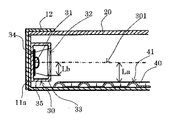
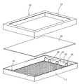
以下本発明のLED面発光装置10の実施例を説明する。図1は本発明に係るLED面発光装置10の実施例を示す断面図であり、図2は図1の光源部の拡大図である。図3は光拡散部材40の拡散面凸部41と光軸301の実施例を示す正面図である。図4は拡散面凸部41の形状を示す断面図である。図5はLED面発光装置10全体の構成部を示す分解図である。 Examples of the LED surface
図1に示す箱状体本体11の内寸法を縦405mm、横690mm、高さ33mmとし、箱状体上部12の上面前面開口部へ半透過性表示パネル20を着脱可能に取り付け、箱状体本体11底面部へは光拡散部材40の光拡散面を半透過性表示パネル20側へ向けて前記箱状体本体11の底面部へ密着させて敷設した。箱状体本体11の縦側左右の箱状体壁部11aには2個のLED光源モジュール30を互いに対向して取り付け、LED光源モジュール30内のLED光源31のレンズ部材32における垂直方向出射光の光軸301までの距離がLb=10mmの時、光軸301から光拡散部材40の拡散面凸部41頂点までの距離を実施例ではLa=15〜16mmに設定している。 The inner dimensions of the box-shaped
図1の半透過性表示パネル20は、厚さ3mmの乳白色アクリル板(三菱レイヨン株式会社製、商品名アクリライト)全光線透過率が58%で全光線反射率が40%を用いる。 The
図1、3に示す光拡散部材40は厚さ0.5mmのポリカーボネート白色シートで全光線反射率が95〜98%を用い、拡散面凸部41は真空成型により前記半透過性表示パネル20と対向した方向へLED光源31の光軸301に対して45°傾斜した斜め格子状の連続した拡散面凸部41を対角線方向のピッチがP=14mm間隔で配置し、図4に示す凸部の断面形状は底部の幅をB=5mm、高さh=1.5mmに設定し、凸部先端を曲線により構成した。 The
図1、2に示すLED光源モジュール30は、光源の構成部品全体を収納するハウジング35と該ハウジング35の内部へ収納される3個のLED光源31は、前記LED光源モジュール30の幅方向の中心線上へLED光源31の光軸301が位置するように配置し、長手方向の中央を基準として左右等間隔の位置へLED光源31の光軸が位置するように配設した。LED光源31は、レンズ部材32と、カバー33と回路基板34から構成され、回路基板34へ3個のLED光源31が実装され、前記カバー33により、LED光源31の取り付け位置が決められている。前記LED光源31の光出射部へはレンズ部材32が配設され該レンズ部材32により、LED光源31の光の出射角が決められ、垂直方向の出射角が光軸対して、外側へ8°、水平方向の出射角を光軸に対して、外側へ20〜30°に設定した。また光源の構成部品全体を収納するハウジング35はアルミニウムの押し出し成型により構成した。 The LED
半透過性表示パネル20の表示面を照度計(株式会社カスタム製 型名:LX−1000)にて測定した。測定は横方向測定位置において箱状体本体11の内側より45mmの位置を▲1▼とし、▲1▼、▲2▼、▲3▼、▲4▼、▲5▼、▲6▼の各間隔を120mmとした。縦方向は箱状体本体11の内側より52mmの位置をAとし、A、B、C、Dの各間隔を100mmとし、横方向測定位置と交差する点24箇所の表面照度を測定した。測定結果は測定点24箇所の横方向測定位置▲1▼〜▲6▼における、縦方向測定位置A、B、C、Dの平均値を表1に示す。本発明のLED面発光装置の表面照度ムラが比較例に対して減少することを確認した。The display surface of the
(比較例)
実施例の光拡散部材40を取り除き平坦な厚さ0.5mmのポリカーボネート白色シートで全光線反射率が95〜98%を箱状体本体11底面部へ密着させて敷設した。前記光拡散部材40を取り除き、該白色シートを敷設した以外は実施例と同じ構成とした。表面照度を測定した結果、半透過性表示パネル20の中央部付近の表面照度低下を確認した。(Comparative example)
The

カラー液晶パネルと対向する面へ光拡散部材を配置し、カラー液晶ディスプレィ全体の箱状体を構成する内面側壁部へLED光源を設け、該LED光源からの出射光を光拡散部材を介して前記カラー液晶パネルへ拡散反射させることによって、カラー液晶ディスプレィのバックライトとしての用途にも適用できる。 A light diffusing member is disposed on the surface facing the color liquid crystal panel, an LED light source is provided on the inner side wall portion constituting the box-shaped body of the entire color liquid crystal display, and the emitted light from the LED light source is transmitted through the light diffusing member through the light diffusing member. By diffusing and reflecting to the color liquid crystal panel, it can also be used as a backlight for a color liquid crystal display.
10 LED面発光装置
11 箱状体本体
11a 箱状体側壁部
12 箱状体上部
20 半透過性表示パネル
30 LED光源モジュール
31 LED光源
32 レンズ部材
33 カバー
34 回路基板
35 ハウジング
40 光拡散部材
41 拡散面凸部
301 光軸DESCRIPTION OF
Claims (7)
Priority Applications (1)
| Application Number | Priority Date | Filing Date | Title |
|---|---|---|---|
| JP2012150854A JP2014002995A (en) | 2012-06-19 | 2012-06-19 | Led surface light-emitting device |
Applications Claiming Priority (1)
| Application Number | Priority Date | Filing Date | Title |
|---|---|---|---|
| JP2012150854A JP2014002995A (en) | 2012-06-19 | 2012-06-19 | Led surface light-emitting device |
Publications (1)
| Publication Number | Publication Date |
|---|---|
| JP2014002995A true JP2014002995A (en) | 2014-01-09 |
Family
ID=50035959
Family Applications (1)
| Application Number | Title | Priority Date | Filing Date |
|---|---|---|---|
| JP2012150854A Pending JP2014002995A (en) | 2012-06-19 | 2012-06-19 | Led surface light-emitting device |
Country Status (1)
| Country | Link |
|---|---|
| JP (1) | JP2014002995A (en) |
Cited By (2)
| Publication number | Priority date | Publication date | Assignee | Title |
|---|---|---|---|---|
| JP2017142933A (en) * | 2016-02-09 | 2017-08-17 | 不二サッシ株式会社 | Interior building material |
| KR101861183B1 (en) * | 2016-11-16 | 2018-05-25 | 주식회사 동우전자 | Led lamp with edge type and emboshing sheet without light guide plate |
-
2012
- 2012-06-19 JP JP2012150854A patent/JP2014002995A/en active Pending
Cited By (2)
| Publication number | Priority date | Publication date | Assignee | Title |
|---|---|---|---|---|
| JP2017142933A (en) * | 2016-02-09 | 2017-08-17 | 不二サッシ株式会社 | Interior building material |
| KR101861183B1 (en) * | 2016-11-16 | 2018-05-25 | 주식회사 동우전자 | Led lamp with edge type and emboshing sheet without light guide plate |
Similar Documents
| Publication | Publication Date | Title |
|---|---|---|
| JP4159059B2 (en) | Planar light source unit | |
| JP5512380B2 (en) | Display device | |
| JP4528902B2 (en) | LIGHT SOURCE DEVICE, LIGHTING DEVICE, AND DISPLAY DEVICE | |
| WO2010004610A1 (en) | Light guide plate unit and lighting apparatus using the light guide plate unit | |
| JPWO2012081187A1 (en) | Backlight device and liquid crystal display device | |
| JP2007059285A (en) | Lighting fixture | |
| JP2006202729A (en) | Led light source light box | |
| JP2008053203A (en) | Planar light source device, back light unit, and liquid crystal display device | |
| JPWO2012081186A1 (en) | Backlight device, liquid crystal display device and lens | |
| JPWO2012101715A1 (en) | Backlight device and liquid crystal display device | |
| CN201851960U (en) | Thin type straightly-downward LED (light-emitting diode) backlight module | |
| WO2013151120A1 (en) | Illumination device | |
| JP2014002995A (en) | Led surface light-emitting device | |
| US20160131816A1 (en) | Illumination device | |
| WO2012081185A1 (en) | Backlight device and liquid-crystal display device | |
| JP2014191292A (en) | Display device | |
| JP5597091B2 (en) | Lighting device | |
| JP3154280U (en) | Flat lighting equipment | |
| JP2012037643A (en) | Display device | |
| JP2014038697A (en) | Backlight device and liquid crystal display | |
| JP2013077791A (en) | Led surface emitting apparatus | |
| WO2013151121A1 (en) | Illumination device | |
| KR20070101656A (en) | Transparent plastic light guide panel and illumination apparatus with light guide panel | |
| CN220455639U (en) | Backlight module capable of reducing light leakage and display equipment | |
| CN215495865U (en) | Lamp fitting |