JP2013540080A - Substantially rigid collapsible liner, liner for container and / or glass bottle replacement and reinforced rigid liner - Google Patents
Substantially rigid collapsible liner, liner for container and / or glass bottle replacement and reinforced rigid liner Download PDFInfo
- Publication number
- JP2013540080A JP2013540080A JP2013533906A JP2013533906A JP2013540080A JP 2013540080 A JP2013540080 A JP 2013540080A JP 2013533906 A JP2013533906 A JP 2013533906A JP 2013533906 A JP2013533906 A JP 2013533906A JP 2013540080 A JP2013540080 A JP 2013540080A
- Authority
- JP
- Japan
- Prior art keywords
- liner
- overpack
- based system
- dispensing
- present disclosure
- Prior art date
- Legal status (The legal status is an assumption and is not a legal conclusion. Google has not performed a legal analysis and makes no representation as to the accuracy of the status listed.)
- Pending
Links
- 239000011521 glass Substances 0.000 title claims abstract description 73
- 239000000463 material Substances 0.000 claims abstract description 207
- 238000000034 method Methods 0.000 claims abstract description 106
- 239000007788 liquid Substances 0.000 claims description 133
- 238000009826 distribution Methods 0.000 claims description 105
- 238000000576 coating method Methods 0.000 claims description 49
- 239000010410 layer Substances 0.000 claims description 42
- 239000011248 coating agent Substances 0.000 claims description 39
- 239000000126 substance Substances 0.000 claims description 30
- 239000002585 base Substances 0.000 claims description 23
- 238000011049 filling Methods 0.000 claims description 23
- 230000004888 barrier function Effects 0.000 claims description 22
- 239000002274 desiccant Substances 0.000 claims description 19
- 229920000642 polymer Polymers 0.000 claims description 19
- 239000000853 adhesive Substances 0.000 claims description 14
- 230000001070 adhesive effect Effects 0.000 claims description 14
- 239000000523 sample Substances 0.000 claims description 13
- 239000002904 solvent Substances 0.000 claims description 13
- 239000002019 doping agent Substances 0.000 claims description 12
- 229920002120 photoresistant polymer Polymers 0.000 claims description 12
- 239000003814 drug Substances 0.000 claims description 11
- 239000002253 acid Substances 0.000 claims description 10
- 238000011143 downstream manufacturing Methods 0.000 claims description 7
- 239000004814 polyurethane Substances 0.000 claims description 7
- 229920002635 polyurethane Polymers 0.000 claims description 7
- 230000002285 radioactive effect Effects 0.000 claims description 7
- BOTDANWDWHJENH-UHFFFAOYSA-N Tetraethyl orthosilicate Chemical compound CCO[Si](OCC)(OCC)OCC BOTDANWDWHJENH-UHFFFAOYSA-N 0.000 claims description 6
- 239000003153 chemical reaction reagent Substances 0.000 claims description 6
- 230000008878 coupling Effects 0.000 claims description 5
- 238000010168 coupling process Methods 0.000 claims description 5
- 238000005859 coupling reaction Methods 0.000 claims description 5
- 239000003599 detergent Substances 0.000 claims description 5
- 239000008157 edible vegetable oil Substances 0.000 claims description 5
- 230000036541 health Effects 0.000 claims description 5
- 239000000575 pesticide Substances 0.000 claims description 5
- 239000002002 slurry Substances 0.000 claims description 5
- 235000014214 soft drink Nutrition 0.000 claims description 5
- 239000012459 cleaning agent Substances 0.000 claims description 4
- 239000002537 cosmetic Substances 0.000 claims description 4
- 235000013305 food Nutrition 0.000 claims description 4
- 239000002920 hazardous waste Substances 0.000 claims description 4
- 238000003780 insertion Methods 0.000 claims description 4
- 230000037431 insertion Effects 0.000 claims description 4
- 239000000314 lubricant Substances 0.000 claims description 4
- 239000003973 paint Substances 0.000 claims description 4
- 239000003208 petroleum Substances 0.000 claims description 4
- 239000000565 sealant Substances 0.000 claims description 4
- 238000012371 Aseptic Filling Methods 0.000 claims description 3
- 239000000919 ceramic Substances 0.000 claims description 3
- 239000000499 gel Substances 0.000 claims description 3
- 239000004973 liquid crystal related substance Substances 0.000 claims description 3
- 239000002086 nanomaterial Substances 0.000 claims description 3
- 230000008569 process Effects 0.000 abstract description 42
- 238000003860 storage Methods 0.000 abstract description 42
- 239000004065 semiconductor Substances 0.000 abstract description 6
- 230000004048 modification Effects 0.000 abstract description 2
- 238000012986 modification Methods 0.000 abstract description 2
- 239000007789 gas Substances 0.000 description 112
- 229910052751 metal Inorganic materials 0.000 description 44
- 239000002184 metal Substances 0.000 description 44
- 239000011112 polyethylene naphthalate Substances 0.000 description 38
- 229920003207 poly(ethylene-2,6-naphthalate) Polymers 0.000 description 33
- 230000002829 reductive effect Effects 0.000 description 33
- 238000004519 manufacturing process Methods 0.000 description 30
- 230000007246 mechanism Effects 0.000 description 28
- 238000000071 blow moulding Methods 0.000 description 25
- 229920003023 plastic Polymers 0.000 description 23
- 239000004033 plastic Substances 0.000 description 23
- -1 polyethylene terephthalate Polymers 0.000 description 17
- 230000002265 prevention Effects 0.000 description 16
- XLYOFNOQVPJJNP-UHFFFAOYSA-N water Substances O XLYOFNOQVPJJNP-UHFFFAOYSA-N 0.000 description 16
- 238000013461 design Methods 0.000 description 15
- 229920000139 polyethylene terephthalate Polymers 0.000 description 15
- 239000005020 polyethylene terephthalate Substances 0.000 description 15
- 238000007373 indentation Methods 0.000 description 14
- 230000001965 increasing effect Effects 0.000 description 13
- 230000013011 mating Effects 0.000 description 13
- 239000012530 fluid Substances 0.000 description 12
- 239000002245 particle Substances 0.000 description 12
- 238000010102 injection blow moulding Methods 0.000 description 11
- 230000001681 protective effect Effects 0.000 description 11
- 230000004044 response Effects 0.000 description 11
- 230000008901 benefit Effects 0.000 description 10
- 238000005266 casting Methods 0.000 description 10
- 230000033001 locomotion Effects 0.000 description 10
- 239000012528 membrane Substances 0.000 description 10
- 239000000203 mixture Substances 0.000 description 10
- 229920001971 elastomer Polymers 0.000 description 9
- 239000000243 solution Substances 0.000 description 9
- 230000007704 transition Effects 0.000 description 9
- 239000004698 Polyethylene Substances 0.000 description 8
- 150000007513 acids Chemical class 0.000 description 8
- 239000007799 cork Substances 0.000 description 8
- 230000002708 enhancing effect Effects 0.000 description 8
- 238000004806 packaging method and process Methods 0.000 description 8
- 229920000573 polyethylene Polymers 0.000 description 8
- 238000003466 welding Methods 0.000 description 8
- 238000013459 approach Methods 0.000 description 7
- 230000000903 blocking effect Effects 0.000 description 7
- 230000000295 complement effect Effects 0.000 description 7
- 230000007423 decrease Effects 0.000 description 7
- 229920001903 high density polyethylene Polymers 0.000 description 7
- 230000006872 improvement Effects 0.000 description 7
- 239000007924 injection Substances 0.000 description 7
- 230000035515 penetration Effects 0.000 description 7
- 230000035699 permeability Effects 0.000 description 7
- 239000004593 Epoxy Substances 0.000 description 6
- 238000011109 contamination Methods 0.000 description 6
- 239000000975 dye Substances 0.000 description 6
- 239000004700 high-density polyethylene Substances 0.000 description 6
- 238000002347 injection Methods 0.000 description 6
- 239000005060 rubber Substances 0.000 description 6
- 230000037303 wrinkles Effects 0.000 description 6
- 230000000712 assembly Effects 0.000 description 5
- 238000000429 assembly Methods 0.000 description 5
- 229920001577 copolymer Polymers 0.000 description 5
- 239000000428 dust Substances 0.000 description 5
- 239000010408 film Substances 0.000 description 5
- 230000005484 gravity Effects 0.000 description 5
- PXHVJJICTQNCMI-UHFFFAOYSA-N nickel Substances [Ni] PXHVJJICTQNCMI-UHFFFAOYSA-N 0.000 description 5
- 229920001343 polytetrafluoroethylene Polymers 0.000 description 5
- 239000004810 polytetrafluoroethylene Substances 0.000 description 5
- 230000001012 protector Effects 0.000 description 5
- 238000004064 recycling Methods 0.000 description 5
- CURLTUGMZLYLDI-UHFFFAOYSA-N Carbon dioxide Chemical compound O=C=O CURLTUGMZLYLDI-UHFFFAOYSA-N 0.000 description 4
- 229920001774 Perfluoroether Polymers 0.000 description 4
- 239000004743 Polypropylene Substances 0.000 description 4
- 229910052782 aluminium Inorganic materials 0.000 description 4
- XAGFODPZIPBFFR-UHFFFAOYSA-N aluminium Chemical compound [Al] XAGFODPZIPBFFR-UHFFFAOYSA-N 0.000 description 4
- 238000007664 blowing Methods 0.000 description 4
- 238000001514 detection method Methods 0.000 description 4
- 238000010586 diagram Methods 0.000 description 4
- 230000000694 effects Effects 0.000 description 4
- 239000012632 extractable Substances 0.000 description 4
- 238000010103 injection stretch blow moulding Methods 0.000 description 4
- 230000000670 limiting effect Effects 0.000 description 4
- 238000005259 measurement Methods 0.000 description 4
- 238000012856 packing Methods 0.000 description 4
- 229920002493 poly(chlorotrifluoroethylene) Polymers 0.000 description 4
- 239000005023 polychlorotrifluoroethylene (PCTFE) polymer Substances 0.000 description 4
- 229920001155 polypropylene Polymers 0.000 description 4
- 238000007789 sealing Methods 0.000 description 4
- 229920000049 Carbon (fiber) Polymers 0.000 description 3
- 229920000219 Ethylene vinyl alcohol Polymers 0.000 description 3
- 239000004812 Fluorinated ethylene propylene Substances 0.000 description 3
- 239000004677 Nylon Substances 0.000 description 3
- 229910000831 Steel Inorganic materials 0.000 description 3
- 239000003463 adsorbent Substances 0.000 description 3
- QVGXLLKOCUKJST-UHFFFAOYSA-N atomic oxygen Chemical compound [O] QVGXLLKOCUKJST-UHFFFAOYSA-N 0.000 description 3
- 230000015572 biosynthetic process Effects 0.000 description 3
- 239000004917 carbon fiber Substances 0.000 description 3
- 239000012792 core layer Substances 0.000 description 3
- 238000005336 cracking Methods 0.000 description 3
- 238000012217 deletion Methods 0.000 description 3
- 230000037430 deletion Effects 0.000 description 3
- 239000000806 elastomer Substances 0.000 description 3
- 125000003700 epoxy group Chemical group 0.000 description 3
- UFRKOOWSQGXVKV-UHFFFAOYSA-N ethene;ethenol Chemical compound C=C.OC=C UFRKOOWSQGXVKV-UHFFFAOYSA-N 0.000 description 3
- 239000004715 ethylene vinyl alcohol Substances 0.000 description 3
- 238000007689 inspection Methods 0.000 description 3
- 238000011068 loading method Methods 0.000 description 3
- 229920001684 low density polyethylene Polymers 0.000 description 3
- 239000004702 low-density polyethylene Substances 0.000 description 3
- 229920001179 medium density polyethylene Polymers 0.000 description 3
- 239000004701 medium-density polyethylene Substances 0.000 description 3
- 238000004377 microelectronic Methods 0.000 description 3
- 238000000465 moulding Methods 0.000 description 3
- 229920001778 nylon Polymers 0.000 description 3
- 150000002894 organic compounds Chemical class 0.000 description 3
- 239000001301 oxygen Substances 0.000 description 3
- 229910052760 oxygen Inorganic materials 0.000 description 3
- 229920009441 perflouroethylene propylene Polymers 0.000 description 3
- 229920000647 polyepoxide Polymers 0.000 description 3
- 238000012545 processing Methods 0.000 description 3
- 230000009467 reduction Effects 0.000 description 3
- 229920005989 resin Polymers 0.000 description 3
- 239000011347 resin Substances 0.000 description 3
- 229920000431 shape-memory polymer Polymers 0.000 description 3
- 238000005507 spraying Methods 0.000 description 3
- 239000010959 steel Substances 0.000 description 3
- 239000002344 surface layer Substances 0.000 description 3
- 229910021654 trace metal Inorganic materials 0.000 description 3
- 239000002699 waste material Substances 0.000 description 3
- OKTJSMMVPCPJKN-UHFFFAOYSA-N Carbon Chemical compound [C] OKTJSMMVPCPJKN-UHFFFAOYSA-N 0.000 description 2
- 229920001651 Cyanoacrylate Polymers 0.000 description 2
- 229910004298 SiO 2 Inorganic materials 0.000 description 2
- VYPSYNLAJGMNEJ-UHFFFAOYSA-N Silicium dioxide Chemical compound O=[Si]=O VYPSYNLAJGMNEJ-UHFFFAOYSA-N 0.000 description 2
- 239000002250 absorbent Substances 0.000 description 2
- 230000002745 absorbent Effects 0.000 description 2
- 230000009471 action Effects 0.000 description 2
- 239000000654 additive Substances 0.000 description 2
- 229910052799 carbon Inorganic materials 0.000 description 2
- 229910002092 carbon dioxide Inorganic materials 0.000 description 2
- 239000001569 carbon dioxide Substances 0.000 description 2
- 230000008859 change Effects 0.000 description 2
- 238000004140 cleaning Methods 0.000 description 2
- 239000003086 colorant Substances 0.000 description 2
- 239000010949 copper Substances 0.000 description 2
- 230000003247 decreasing effect Effects 0.000 description 2
- 229940079593 drug Drugs 0.000 description 2
- 238000004049 embossing Methods 0.000 description 2
- 230000007613 environmental effect Effects 0.000 description 2
- 238000001125 extrusion Methods 0.000 description 2
- 238000010101 extrusion blow moulding Methods 0.000 description 2
- 229920002313 fluoropolymer Polymers 0.000 description 2
- 239000004811 fluoropolymer Substances 0.000 description 2
- 230000006870 function Effects 0.000 description 2
- LNTHITQWFMADLM-UHFFFAOYSA-N gallic acid Chemical compound OC(=O)C1=CC(O)=C(O)C(O)=C1 LNTHITQWFMADLM-UHFFFAOYSA-N 0.000 description 2
- 239000003317 industrial substance Substances 0.000 description 2
- 239000000976 ink Substances 0.000 description 2
- 238000009434 installation Methods 0.000 description 2
- 230000003993 interaction Effects 0.000 description 2
- 239000007769 metal material Substances 0.000 description 2
- 229910044991 metal oxide Inorganic materials 0.000 description 2
- 150000004706 metal oxides Chemical class 0.000 description 2
- 150000002739 metals Chemical class 0.000 description 2
- VNWKTOKETHGBQD-UHFFFAOYSA-N methane Chemical compound C VNWKTOKETHGBQD-UHFFFAOYSA-N 0.000 description 2
- 238000012544 monitoring process Methods 0.000 description 2
- 239000002105 nanoparticle Substances 0.000 description 2
- 229920005615 natural polymer Polymers 0.000 description 2
- 229910052759 nickel Inorganic materials 0.000 description 2
- 239000000049 pigment Substances 0.000 description 2
- 229920000218 poly(hydroxyvalerate) Polymers 0.000 description 2
- 229920000070 poly-3-hydroxybutyrate Polymers 0.000 description 2
- 229920001610 polycaprolactone Polymers 0.000 description 2
- 239000004632 polycaprolactone Substances 0.000 description 2
- 229920002792 polyhydroxyhexanoate Polymers 0.000 description 2
- 229920000098 polyolefin Polymers 0.000 description 2
- 230000002787 reinforcement Effects 0.000 description 2
- GHMLBKRAJCXXBS-UHFFFAOYSA-N resorcinol Chemical compound OC1=CC=CC(O)=C1 GHMLBKRAJCXXBS-UHFFFAOYSA-N 0.000 description 2
- 230000000630 rising effect Effects 0.000 description 2
- 239000007787 solid Substances 0.000 description 2
- 238000001179 sorption measurement Methods 0.000 description 2
- 229910001220 stainless steel Inorganic materials 0.000 description 2
- 239000010935 stainless steel Substances 0.000 description 2
- 229920001059 synthetic polymer Polymers 0.000 description 2
- 239000011345 viscous material Substances 0.000 description 2
- 238000004804 winding Methods 0.000 description 2
- ZMKVBUOZONDYBW-UHFFFAOYSA-N 1,6-dioxecane-2,5-dione Chemical compound O=C1CCC(=O)OCCCCO1 ZMKVBUOZONDYBW-UHFFFAOYSA-N 0.000 description 1
- VXEGSRKPIUDPQT-UHFFFAOYSA-N 4-[4-(4-methoxyphenyl)piperazin-1-yl]aniline Chemical compound C1=CC(OC)=CC=C1N1CCN(C=2C=CC(N)=CC=2)CC1 VXEGSRKPIUDPQT-UHFFFAOYSA-N 0.000 description 1
- IJGRMHOSHXDMSA-UHFFFAOYSA-N Atomic nitrogen Chemical compound N#N IJGRMHOSHXDMSA-UHFFFAOYSA-N 0.000 description 1
- XMWRBQBLMFGWIX-UHFFFAOYSA-N C60 fullerene Chemical class C12=C3C(C4=C56)=C7C8=C5C5=C9C%10=C6C6=C4C1=C1C4=C6C6=C%10C%10=C9C9=C%11C5=C8C5=C8C7=C3C3=C7C2=C1C1=C2C4=C6C4=C%10C6=C9C9=C%11C5=C5C8=C3C3=C7C1=C1C2=C4C6=C2C9=C5C3=C12 XMWRBQBLMFGWIX-UHFFFAOYSA-N 0.000 description 1
- 229920002160 Celluloid Polymers 0.000 description 1
- RYGMFSIKBFXOCR-UHFFFAOYSA-N Copper Chemical compound [Cu] RYGMFSIKBFXOCR-UHFFFAOYSA-N 0.000 description 1
- 229920010126 Linear Low Density Polyethylene (LLDPE) Polymers 0.000 description 1
- MWCLLHOVUTZFKS-UHFFFAOYSA-N Methyl cyanoacrylate Chemical compound COC(=O)C(=C)C#N MWCLLHOVUTZFKS-UHFFFAOYSA-N 0.000 description 1
- 229920000881 Modified starch Polymers 0.000 description 1
- ZOKXTWBITQBERF-UHFFFAOYSA-N Molybdenum Chemical compound [Mo] ZOKXTWBITQBERF-UHFFFAOYSA-N 0.000 description 1
- 239000000020 Nitrocellulose Substances 0.000 description 1
- 229920002732 Polyanhydride Polymers 0.000 description 1
- 239000004372 Polyvinyl alcohol Substances 0.000 description 1
- 229910003902 SiCl 4 Inorganic materials 0.000 description 1
- CDBYLPFSWZWCQE-UHFFFAOYSA-L Sodium Carbonate Chemical compound [Na+].[Na+].[O-]C([O-])=O CDBYLPFSWZWCQE-UHFFFAOYSA-L 0.000 description 1
- FAPWRFPIFSIZLT-UHFFFAOYSA-M Sodium chloride Chemical compound [Na+].[Cl-] FAPWRFPIFSIZLT-UHFFFAOYSA-M 0.000 description 1
- 239000004826 Synthetic adhesive Substances 0.000 description 1
- 229910010413 TiO 2 Inorganic materials 0.000 description 1
- 238000009825 accumulation Methods 0.000 description 1
- 210000004712 air sac Anatomy 0.000 description 1
- PNEYBMLMFCGWSK-UHFFFAOYSA-N aluminium oxide Inorganic materials [O-2].[O-2].[O-2].[Al+3].[Al+3] PNEYBMLMFCGWSK-UHFFFAOYSA-N 0.000 description 1
- 150000001412 amines Chemical class 0.000 description 1
- 238000004873 anchoring Methods 0.000 description 1
- 239000005391 art glass Substances 0.000 description 1
- 239000012298 atmosphere Substances 0.000 description 1
- 229920002678 cellulose Polymers 0.000 description 1
- 229920002301 cellulose acetate Polymers 0.000 description 1
- 238000002144 chemical decomposition reaction Methods 0.000 description 1
- 238000012993 chemical processing Methods 0.000 description 1
- 238000005229 chemical vapour deposition Methods 0.000 description 1
- ZTXONRUJVYXVTJ-UHFFFAOYSA-N chromium copper Chemical compound [Cr][Cu][Cr] ZTXONRUJVYXVTJ-UHFFFAOYSA-N 0.000 description 1
- 229920001688 coating polymer Polymers 0.000 description 1
- 239000000470 constituent Substances 0.000 description 1
- 239000000356 contaminant Substances 0.000 description 1
- 230000008602 contraction Effects 0.000 description 1
- 229910052802 copper Inorganic materials 0.000 description 1
- IUYOGGFTLHZHEG-UHFFFAOYSA-N copper titanium Chemical compound [Ti].[Cu] IUYOGGFTLHZHEG-UHFFFAOYSA-N 0.000 description 1
- 239000006071 cream Substances 0.000 description 1
- NLCKLZIHJQEMCU-UHFFFAOYSA-N cyano prop-2-enoate Chemical class C=CC(=O)OC#N NLCKLZIHJQEMCU-UHFFFAOYSA-N 0.000 description 1
- 238000000151 deposition Methods 0.000 description 1
- 238000003618 dip coating Methods 0.000 description 1
- 238000007598 dipping method Methods 0.000 description 1
- 238000004090 dissolution Methods 0.000 description 1
- 238000001035 drying Methods 0.000 description 1
- 230000005489 elastic deformation Effects 0.000 description 1
- 239000013536 elastomeric material Substances 0.000 description 1
- 230000005611 electricity Effects 0.000 description 1
- 238000000313 electron-beam-induced deposition Methods 0.000 description 1
- 238000009713 electroplating Methods 0.000 description 1
- HQQADJVZYDDRJT-UHFFFAOYSA-N ethene;prop-1-ene Chemical group C=C.CC=C HQQADJVZYDDRJT-UHFFFAOYSA-N 0.000 description 1
- 239000000835 fiber Substances 0.000 description 1
- 229920002457 flexible plastic Polymers 0.000 description 1
- 229910003472 fullerene Inorganic materials 0.000 description 1
- 229940074391 gallic acid Drugs 0.000 description 1
- 235000004515 gallic acid Nutrition 0.000 description 1
- 238000010438 heat treatment Methods 0.000 description 1
- 230000007062 hydrolysis Effects 0.000 description 1
- 238000006460 hydrolysis reaction Methods 0.000 description 1
- 239000012535 impurity Substances 0.000 description 1
- 229920000092 linear low density polyethylene Polymers 0.000 description 1
- 239000004707 linear low-density polyethylene Substances 0.000 description 1
- 230000001050 lubricating effect Effects 0.000 description 1
- 238000003754 machining Methods 0.000 description 1
- 238000000691 measurement method Methods 0.000 description 1
- 239000011104 metalized film Substances 0.000 description 1
- 230000005012 migration Effects 0.000 description 1
- 238000013508 migration Methods 0.000 description 1
- 235000019426 modified starch Nutrition 0.000 description 1
- 229910052750 molybdenum Inorganic materials 0.000 description 1
- 239000011733 molybdenum Substances 0.000 description 1
- 230000000877 morphologic effect Effects 0.000 description 1
- 150000004767 nitrides Chemical class 0.000 description 1
- 229920001220 nitrocellulos Polymers 0.000 description 1
- 230000003647 oxidation Effects 0.000 description 1
- 238000007254 oxidation reaction Methods 0.000 description 1
- 239000005022 packaging material Substances 0.000 description 1
- 239000011087 paperboard Substances 0.000 description 1
- 230000002093 peripheral effect Effects 0.000 description 1
- 238000007747 plating Methods 0.000 description 1
- 229920000728 polyester Polymers 0.000 description 1
- 239000004626 polylactic acid Substances 0.000 description 1
- 229920002451 polyvinyl alcohol Polymers 0.000 description 1
- 239000002243 precursor Substances 0.000 description 1
- 238000002360 preparation method Methods 0.000 description 1
- 238000003825 pressing Methods 0.000 description 1
- 238000005086 pumping Methods 0.000 description 1
- 238000010791 quenching Methods 0.000 description 1
- 230000000171 quenching effect Effects 0.000 description 1
- 239000002994 raw material Substances 0.000 description 1
- 230000009257 reactivity Effects 0.000 description 1
- 230000003014 reinforcing effect Effects 0.000 description 1
- 230000000717 retained effect Effects 0.000 description 1
- 230000035945 sensitivity Effects 0.000 description 1
- 230000008054 signal transmission Effects 0.000 description 1
- 229910052710 silicon Inorganic materials 0.000 description 1
- 239000010703 silicon Substances 0.000 description 1
- 239000000377 silicon dioxide Substances 0.000 description 1
- 239000005049 silicon tetrachloride Substances 0.000 description 1
- 239000011780 sodium chloride Substances 0.000 description 1
- 125000006850 spacer group Chemical group 0.000 description 1
- 239000007921 spray Substances 0.000 description 1
- 238000004544 sputter deposition Methods 0.000 description 1
- 230000003068 static effect Effects 0.000 description 1
- 238000006467 substitution reaction Methods 0.000 description 1
- 239000000758 substrate Substances 0.000 description 1
- 238000012360 testing method Methods 0.000 description 1
- 125000000383 tetramethylene group Chemical group [H]C([H])([*:1])C([H])([H])C([H])([H])C([H])([H])[*:2] 0.000 description 1
- 229920005992 thermoplastic resin Polymers 0.000 description 1
- XJDNKRIXUMDJCW-UHFFFAOYSA-J titanium tetrachloride Chemical compound Cl[Ti](Cl)(Cl)Cl XJDNKRIXUMDJCW-UHFFFAOYSA-J 0.000 description 1
- 229940034610 toothpaste Drugs 0.000 description 1
- 239000000606 toothpaste Substances 0.000 description 1
- 239000012780 transparent material Substances 0.000 description 1
- WFKWXMTUELFFGS-UHFFFAOYSA-N tungsten Chemical compound [W] WFKWXMTUELFFGS-UHFFFAOYSA-N 0.000 description 1
- 229910052721 tungsten Inorganic materials 0.000 description 1
- 239000010937 tungsten Substances 0.000 description 1
- 238000007738 vacuum evaporation Methods 0.000 description 1
- 238000007740 vapor deposition Methods 0.000 description 1
- 230000000007 visual effect Effects 0.000 description 1
- 239000011800 void material Substances 0.000 description 1
- 239000002023 wood Substances 0.000 description 1
Images


Classifications
-
- B—PERFORMING OPERATIONS; TRANSPORTING
- B65—CONVEYING; PACKING; STORING; HANDLING THIN OR FILAMENTARY MATERIAL
- B65D—CONTAINERS FOR STORAGE OR TRANSPORT OF ARTICLES OR MATERIALS, e.g. BAGS, BARRELS, BOTTLES, BOXES, CANS, CARTONS, CRATES, DRUMS, JARS, TANKS, HOPPERS, FORWARDING CONTAINERS; ACCESSORIES, CLOSURES, OR FITTINGS THEREFOR; PACKAGING ELEMENTS; PACKAGES
- B65D77/00—Packages formed by enclosing articles or materials in preformed containers, e.g. boxes, cartons, sacks or bags
- B65D77/04—Articles or materials enclosed in two or more containers disposed one within another
-
- B—PERFORMING OPERATIONS; TRANSPORTING
- B65—CONVEYING; PACKING; STORING; HANDLING THIN OR FILAMENTARY MATERIAL
- B65D—CONTAINERS FOR STORAGE OR TRANSPORT OF ARTICLES OR MATERIALS, e.g. BAGS, BARRELS, BOTTLES, BOXES, CANS, CARTONS, CRATES, DRUMS, JARS, TANKS, HOPPERS, FORWARDING CONTAINERS; ACCESSORIES, CLOSURES, OR FITTINGS THEREFOR; PACKAGING ELEMENTS; PACKAGES
- B65D25/00—Details of other kinds or types of rigid or semi-rigid containers
- B65D25/14—Linings or internal coatings
- B65D25/16—Loose, or loosely-attached, linings
-
- B—PERFORMING OPERATIONS; TRANSPORTING
- B65—CONVEYING; PACKING; STORING; HANDLING THIN OR FILAMENTARY MATERIAL
- B65D—CONTAINERS FOR STORAGE OR TRANSPORT OF ARTICLES OR MATERIALS, e.g. BAGS, BARRELS, BOTTLES, BOXES, CANS, CARTONS, CRATES, DRUMS, JARS, TANKS, HOPPERS, FORWARDING CONTAINERS; ACCESSORIES, CLOSURES, OR FITTINGS THEREFOR; PACKAGING ELEMENTS; PACKAGES
- B65D37/00—Portable flexible containers not otherwise provided for
-
- B—PERFORMING OPERATIONS; TRANSPORTING
- B32—LAYERED PRODUCTS
- B32B—LAYERED PRODUCTS, i.e. PRODUCTS BUILT-UP OF STRATA OF FLAT OR NON-FLAT, e.g. CELLULAR OR HONEYCOMB, FORM
- B32B1/00—Layered products having a general shape other than plane
-
- B—PERFORMING OPERATIONS; TRANSPORTING
- B65—CONVEYING; PACKING; STORING; HANDLING THIN OR FILAMENTARY MATERIAL
- B65D—CONTAINERS FOR STORAGE OR TRANSPORT OF ARTICLES OR MATERIALS, e.g. BAGS, BARRELS, BOTTLES, BOXES, CANS, CARTONS, CRATES, DRUMS, JARS, TANKS, HOPPERS, FORWARDING CONTAINERS; ACCESSORIES, CLOSURES, OR FITTINGS THEREFOR; PACKAGING ELEMENTS; PACKAGES
- B65D23/00—Details of bottles or jars not otherwise provided for
- B65D23/02—Linings or internal coatings
-
- B—PERFORMING OPERATIONS; TRANSPORTING
- B65—CONVEYING; PACKING; STORING; HANDLING THIN OR FILAMENTARY MATERIAL
- B65D—CONTAINERS FOR STORAGE OR TRANSPORT OF ARTICLES OR MATERIALS, e.g. BAGS, BARRELS, BOTTLES, BOXES, CANS, CARTONS, CRATES, DRUMS, JARS, TANKS, HOPPERS, FORWARDING CONTAINERS; ACCESSORIES, CLOSURES, OR FITTINGS THEREFOR; PACKAGING ELEMENTS; PACKAGES
- B65D25/00—Details of other kinds or types of rigid or semi-rigid containers
- B65D25/14—Linings or internal coatings
-
- B—PERFORMING OPERATIONS; TRANSPORTING
- B65—CONVEYING; PACKING; STORING; HANDLING THIN OR FILAMENTARY MATERIAL
- B65D—CONTAINERS FOR STORAGE OR TRANSPORT OF ARTICLES OR MATERIALS, e.g. BAGS, BARRELS, BOTTLES, BOXES, CANS, CARTONS, CRATES, DRUMS, JARS, TANKS, HOPPERS, FORWARDING CONTAINERS; ACCESSORIES, CLOSURES, OR FITTINGS THEREFOR; PACKAGING ELEMENTS; PACKAGES
- B65D83/00—Containers or packages with special means for dispensing contents
- B65D83/0055—Containers or packages provided with a flexible bag or a deformable membrane or diaphragm for expelling the contents
-
- B—PERFORMING OPERATIONS; TRANSPORTING
- B65—CONVEYING; PACKING; STORING; HANDLING THIN OR FILAMENTARY MATERIAL
- B65D—CONTAINERS FOR STORAGE OR TRANSPORT OF ARTICLES OR MATERIALS, e.g. BAGS, BARRELS, BOTTLES, BOXES, CANS, CARTONS, CRATES, DRUMS, JARS, TANKS, HOPPERS, FORWARDING CONTAINERS; ACCESSORIES, CLOSURES, OR FITTINGS THEREFOR; PACKAGING ELEMENTS; PACKAGES
- B65D85/00—Containers, packaging elements or packages, specially adapted for particular articles or materials
- B65D85/70—Containers, packaging elements or packages, specially adapted for particular articles or materials for materials not otherwise provided for
- B65D85/84—Containers, packaging elements or packages, specially adapted for particular articles or materials for materials not otherwise provided for for corrosive chemicals
-
- B—PERFORMING OPERATIONS; TRANSPORTING
- B29—WORKING OF PLASTICS; WORKING OF SUBSTANCES IN A PLASTIC STATE IN GENERAL
- B29L—INDEXING SCHEME ASSOCIATED WITH SUBCLASS B29C, RELATING TO PARTICULAR ARTICLES
- B29L2023/00—Tubular articles
- B29L2023/005—Hoses, i.e. flexible
- B29L2023/006—Flexible liners
-
- Y—GENERAL TAGGING OF NEW TECHNOLOGICAL DEVELOPMENTS; GENERAL TAGGING OF CROSS-SECTIONAL TECHNOLOGIES SPANNING OVER SEVERAL SECTIONS OF THE IPC; TECHNICAL SUBJECTS COVERED BY FORMER USPC CROSS-REFERENCE ART COLLECTIONS [XRACs] AND DIGESTS
- Y10—TECHNICAL SUBJECTS COVERED BY FORMER USPC
- Y10T—TECHNICAL SUBJECTS COVERED BY FORMER US CLASSIFICATION
- Y10T428/00—Stock material or miscellaneous articles
- Y10T428/13—Hollow or container type article [e.g., tube, vase, etc.]
Abstract
本開示は、特に、より小型の保管および分配システムに好適であり得る吹込成形された剛性圧潰可能ライナーに関する。剛性圧潰可能ライナーは、独立型ライナーであり、例えば、外側容器を伴わずに使用されてもよく、固定圧力分配缶から分配されてもよい。剛性圧潰可能ライナーにおける折り目は実質的に排除され、それによって、ピンホール、溶接割れ、および溢流と関連付けられた問題を実質的に低減または排除し得る。本開示はまた、ガラスから作製されるもの等、単純剛性壁容器の代替として使用されるか、またはそれの代用とされ得る、前述のライナーを含む、システムおよびライナーに関する。そのような有利なシステムおよびライナーは、実質的に、エンドユーザの既存のポンプ分配または圧力分配システムに修正を伴うことなく、高純度材料を半導体プロセスに送達するためのシステム内の単純剛性壁容器の代用とされ得る。The present disclosure particularly relates to a blow molded rigid collapsible liner that may be suitable for smaller storage and dispensing systems. The rigid collapsible liner is a stand-alone liner and may be used, for example, without an outer container or dispensed from a fixed pressure dispensing can. The folds in the rigid collapsible liner are substantially eliminated, thereby substantially reducing or eliminating problems associated with pinholes, weld cracks, and overflow. The present disclosure also relates to systems and liners, including the liners described above, that can be used or substituted for simple rigid wall containers, such as those made from glass. Such an advantageous system and liner is a simple rigid wall container in the system for delivering high purity material to a semiconductor process substantially without modification to the end user's existing pump dispensing or pressure dispensing system. Can be substituted.
Description
(関連出願の相互参照)
本願は、国際出願PCT/US10/41629号(名称「Substantially Rigid Collapsible Liner and Flexible Gusseted or Non−gusseted Liners and Methods of Manufacturing the Same and Methods for Limiting Choke−off in Liners」、2010年7月9日出願)、米国特許出願第61/391,945号(名称「Substantially Rigid Collapsible Liner,Container and/or Liner for Replacing Glass Bottles,and Flexible Gusseted or Non−Gusseted Liners」、2010年10月11日出願)、および米国特許出願第61/405,567号(名称「Substantially Rigid Collapsible Liner,Container and/or Liner for Replacing Glass Bottles,and Flexible Gusseted or Non−Gusseted Liners」、2010年10月21日出願)に関連し、これらの出願の各々の内容は、その全体が本明細書に参照によって援用される。
(Cross-reference of related applications)
This application is an international application PCT / US10 / 41629 (name “Substantially Rigid Collapsible Liner and Flexible-Gusted in Non-gusted Linth and Methods of Manufacture of Non-Gustened Led. ), U.S. Patent Application No. 61 / 391,945 (named “Substantially Rigid Collapsible Liner, Container and / or Liner for Replacing Glass Bottles, and Flexible Gustated or G-Non-Golded Lose Non-Gr ners ", filed Oct. 11, 2010), and U.S. Patent Application No. 61 / 405,567 (named" Substantially Rigid Collapsible Liner, Container and Reprinting Glass Bottles, and Fr , Filed October 21, 2010), the contents of each of these applications are hereby incorporated by reference in their entirety.
(発明の分野)
本開示は、ライナーベースの保管および分配システムに関する。より具体的には、本開示は、実質的に剛性の容器、圧潰可能ライナー、および可撓性ガセット付きまたは非ガセット付きライナーと、それらを製造するための方法に関する。本開示はまた、ガラスから作製されるもの等の単純剛性壁容器の代替として、またはその代用とするために使用され得るシステムおよびライナーに関する。本開示はまた、ライナー内での閉塞を制限するための方法に関する。
(Field of Invention)
The present disclosure relates to liner-based storage and dispensing systems. More specifically, the present disclosure relates to substantially rigid containers, collapsible liners, and flexible gusseted or non-gusseted liners and methods for making them. The present disclosure also relates to systems and liners that can be used as an alternative to or to replace simple rigid wall containers such as those made from glass. The present disclosure also relates to a method for limiting occlusion in a liner.
(発明の背景)
多数の製造プロセスは、酸、溶媒、基剤、フォトレジスト、スラリー、洗浄剤、ドーパント、無機物、有機物、金属有機物、および生物学的溶液、医薬品、ならびに放射性化学物質等の超高純度液体の使用を要求する。そのような用途は、超高純度液体中の粒子の数およびサイズが最小であることを要求する。特に、超高純度液体は、マイクロ電子製造プロセスの多くの側面において使用されるので、半導体製造業者は、プロセス化学物質および化学処理機器のための厳密な粒子濃度仕様を確立している。そのような仕様は、製造プロセスの間に、高レベルの粒子または気泡を含有する液体が使用される場合、粒子または気泡がシリコンの固体表面上に堆積され得るので、必要とされる。これは、ひいては、製品故障ならびに品質および信頼性低下につながり得る。
(Background of the Invention)
Many manufacturing processes use acids, solvents, bases, photoresists, slurries, cleaning agents, dopants, inorganics, organics, metal organics, and ultra-high purity liquids such as biological solutions, pharmaceuticals, and radiochemicals Request. Such applications require that the number and size of particles in ultra high purity liquids be minimal. In particular, because ultra-high purity liquids are used in many aspects of microelectronic manufacturing processes, semiconductor manufacturers have established strict particle concentration specifications for process chemicals and chemical processing equipment. Such a specification is required because during the manufacturing process, if liquids containing high levels of particles or bubbles are used, the particles or bubbles can be deposited on the solid surface of silicon. This in turn can lead to product failure and reduced quality and reliability.
故に、そのような高純度液体の保管、運搬、および分配は、貯留される液体に対する適切な保護を提供することが可能な容器を要求する。業界で一般的に使用される2つのタイプの容器は、ガラスまたはプラスチックから作製される単純剛性壁容器と、圧潰可能ライナーベースの容器である。剛性壁容器は、従来、その物理的強度、厚い壁、安価なコスト、および製造の容易性のために使用されている。しかしながら、そのような容器は、液体を圧力分配するときに、気液界面をもたらし得る。この圧力増加は、フォトレジスト等、容器内に貯留される液体中にガスを溶解させ、分配系統において液体中の望ましくない粒子および気泡生成につながり得る。 Therefore, storage, transport and distribution of such high purity liquids require containers that can provide adequate protection against the stored liquid. Two types of containers commonly used in the industry are simple rigid wall containers made from glass or plastic and collapsible liner-based containers. Rigid wall containers are traditionally used because of their physical strength, thick walls, low cost, and ease of manufacture. However, such containers can provide a gas-liquid interface when pressure dispensing liquid. This pressure increase can dissolve the gas in the liquid stored in the container, such as photoresist, and can lead to undesirable particle and bubble generation in the liquid in the distribution system.
代替として、ATMI,Inc.製のNOWPak(登録商標)分配システム等の圧潰可能ライナーベースの容器は、分配中に、容器内の液体を直接的にガスで加圧することとは対照的に、ライナーをガスで加圧することによって、そのような気液界面を減少させることが可能である。しかしながら、公知のライナーは、環境条件に対して適切な保護を提供するために使用することが不可能であり得る。例えば、現在のライナーベースの容器は、容器の運搬によってもたらされるもの等、時として、振動からの弾性変形によって生じるピンホール破損および溶接割れに対して、貯留された液体を保護できない場合がある。運搬からの振動は、ライナーを出荷場所と最終仕向地との間で何度も(例えば、何千から何百万回)弾性変形または撓曲させ得る。振動が大きいほど、ピンホールおよび溶接割れが生じることになる可能性が高まる。ピンホールおよび溶接割れの他の原因として、衝撃効果、落下、または容器の大きな振幅動作が挙げられる。ガスは、ピンホールまたは溶接割れを通して導入され、それによって、ガスが溶液中に入り込み、気泡としてウエハ上に現れるので、貯留された液体を経時的に汚染させ得る。 As an alternative, ATMI, Inc. Crushable liner-based containers such as the NOWWPak® dispensing system made by gas pressurizing the liner with gas during dispensing, as opposed to directly pressurizing the liquid in the container with gas. It is possible to reduce such a gas-liquid interface. However, known liners may not be able to be used to provide adequate protection against environmental conditions. For example, current liner-based containers sometimes fail to protect stored liquids against pinhole breakage and weld cracks caused by elastic deformation from vibration, such as those provided by container transport. Vibrations from transport can cause the liner to elastically deform or flex many times (eg, thousands to millions) between the shipping location and the final destination. The greater the vibration, the greater the likelihood that pinholes and weld cracks will occur. Other causes of pinholes and weld cracks include impact effects, drops, or large amplitude motion of the container. Gas is introduced through pinholes or weld cracks, which can contaminate the stored liquid over time as the gas enters the solution and appears on the wafer as bubbles.
加えて、圧潰可能ライナーは、規定量の液体で充填されるように構成される。しかしながら、ライナーは、容器の内側に嵌合されると、折り目がライナー内に生成されるので、その別個の外側容器の中に整然とは嵌合しない。折り目は、折り目によって占有される空間におけるライナーの液体充填を妨げ得る。故に、容器が、規定量の液体で充填されると、液体は、容器から溢流し、液体の損失をもたらす傾向にある。前述のように、そのような液体は、一般的には、酸、溶媒、基剤、フォトレジスト、ドーパント、無機体、有機体、および生物学的溶液、医薬品、ならびに放射性化学物質等の高純度液体であって、例えば、約$2,500/L以上と、非常に高価であり得る。したがって、少量の溢流でも、望ましくない。 In addition, the collapsible liner is configured to be filled with a defined amount of liquid. However, when the liner is fitted inside the container, a crease is created in the liner and therefore does not fit in order in its separate outer container. The crease may prevent liquid filling of the liner in the space occupied by the crease. Thus, when a container is filled with a defined amount of liquid, the liquid tends to overflow from the container and cause liquid loss. As mentioned above, such liquids are generally high purity such as acids, solvents, bases, photoresists, dopants, inorganics, organisms, and biological solutions, pharmaceuticals, and radiochemicals. The liquid may be very expensive, for example, about $ 2,500 / L or more. Therefore, even a small amount of overflow is undesirable.
したがって、当技術分野で必要とされるのは、従来の剛性壁および圧潰可能ライナーベースの容器によって提示される不利点を含まない、高純度液体のためのより優れたライナーシステムである。当技術分野で必要とされるのは、実質的に剛性の圧潰可能ライナーおよび可撓性襠付きまたは非襠付きライナーである。当技術分野で必要とされるのは、ピンホール、溶接割れ、ガス圧力飽和、および溢流と関連付けられた問題に対処する、ライナーベースの保管および分配システムである。当技術分野で必要とされるのは、ライナー内に付加的捕捉ガスをもたらし得る、ライナーにおける過剰折り目と関連付けられた問題に対処する、ライナーベースの保管および分配システムである。また、当技術分野で必要とされるのは、閉塞が制限または排除されるように構成されるライナーである。 Therefore, what is needed in the art is a better liner system for high purity liquids that does not include the disadvantages presented by conventional rigid walls and collapsible liner-based containers. What is needed in the art is a substantially rigid collapsible liner and a flexible or non-barbed liner. What is needed in the art is a liner-based storage and distribution system that addresses the problems associated with pinholes, weld cracking, gas pressure saturation, and overflow. What is needed in the art is a liner-based storage and dispensing system that addresses the problems associated with overfolding in the liner that can result in additional trapped gas in the liner. What is also needed in the art is a liner configured to limit or eliminate occlusion.
本開示は、一実施形態では、オーバーパックおよびライナーを含む、ライナーベースの保管システムに関する。ライナーは、オーバーパック内に提供されてもよい。ライナーは、ライナーの内部空洞を形成する、実質的に剛性のライナー壁を有してもよく、剛性ライナー壁は、ライナーが、拡張状態では、実質的に、自立するが、約20psi未満の圧力では、圧潰可能であって、内部空洞内から流体を分配するような厚さを有する。 The present disclosure, in one embodiment, relates to a liner-based storage system that includes an overpack and a liner. The liner may be provided in an overpack. The liner may have a substantially rigid liner wall that forms an internal cavity of the liner, the rigid liner wall being substantially free standing when the liner is in an expanded state, but with a pressure less than about 20 psi. Then, it is crushable and has a thickness that distributes fluid from within the internal cavity.
本開示は、別の実施形態では、ライナーの内部空洞を形成するライナー壁と、概して、ライナーの底部にあって、分配能力を増加させる、サンプ領域とを有する、ライナーに関する。 The present disclosure, in another embodiment, relates to a liner having a liner wall that forms an interior cavity of the liner and a sump region that is generally at the bottom of the liner and increases dispensing capacity.
本開示は、別の実施形態では、さらに、閉塞を防止するための手段を含む、ライナーに関する。 The present disclosure, in another embodiment, further relates to a liner that includes means for preventing occlusion.
本開示は、別の実施形態では、剛性壁容器の代用とするためのライナーに関する。ライナーは、材料を保持するためのライナーの内部空洞を形成する、ライナー壁を含む。ライナー壁は、防湿コーティングの有無にかかわらず、ポリエチレンナフタレート(PEN)から作製される。ライナーはまた、材料をライナーの内部空洞内に導入し、ライナーの内部空洞から材料を分配するために、ライナー壁に取着される、嵌合部を含む。 The present disclosure, in another embodiment, relates to a liner for substituting a rigid wall container. The liner includes a liner wall that forms an internal cavity of the liner for holding material. The liner wall is made of polyethylene naphthalate (PEN) with or without moisture barrier coating. The liner also includes a mating portion that is attached to the liner wall to introduce material into the interior cavity of the liner and dispense material from the interior cavity of the liner.
他の実施形態では、本開示は、剛性壁容器の代用とするためのライナーシステムに関する。ライナーシステムは、材料を保持するための内部空洞を形成するライナーを含む。ライナーは、ポリエチレンナフタレート(PEN)から作製される。ライナーシステムはまた、ライナーの内部空洞に通過する湿気を低減されるために、少なくとも1つの乾燥剤を含む。 In other embodiments, the present disclosure relates to a liner system for substituting a rigid wall container. The liner system includes a liner that forms an internal cavity for holding material. The liner is made from polyethylene naphthalate (PEN). The liner system also includes at least one desiccant to reduce moisture passing through the inner cavity of the liner.
別の実施形態では、本開示は、その中に保管される高純度材料を有する実質的に剛性の自立容器を提供するステップを含む、高純度材料を半導体プロセスに送達する方法に関する。容器は、ポリエチレンナフタレート(PEN)を備える容器壁と、内部にそこから高純度材料を分配するための浸漬管とを有する。浸漬管は、下流半導体プロセスに連結される。方法はまた、浸漬管を介して、容器から高純度材料を分配するステップと、高純度材料を下流半導体プロセスに送達するステップとを含む。 In another embodiment, the present disclosure is directed to a method of delivering a high purity material to a semiconductor process comprising providing a substantially rigid self-supporting container having the high purity material stored therein. The container has a container wall comprising polyethylene naphthalate (PEN) and a dip tube for dispensing high purity material therefrom therein. The dip tube is connected to a downstream semiconductor process. The method also includes dispensing high purity material from the container via a dip tube and delivering the high purity material to a downstream semiconductor process.
なおもさらなる実施形態では、本開示は、オーバーパックと、オーバーパック内に提供されるライナーとを含み、ライナーは、口部と、ライナーの内部空洞を形成し、ライナーが拡張状態において実質的に自立しているが、約20psi未満の圧力では圧潰可能であるような厚さを有するライナー壁とを有する、ライナーベースのシステムに関する。ライナーは、ライナーとオーバーパックとの間の環状空間内へのガスまたは液体の導入に応じて、オーバーパックの内部壁から離れるように圧潰し、それによって、ライナーの内容物を分配するように構成されてもよい。ライナーおよび/またはオーバーパックは、ライナーの圧潰を制御するための1つ以上の表面特徴を有してもよい。1つ以上の表面特徴は、特定の実施形態では、ライナーおよび/またはオーバーパックの円周の周囲に離間した複数の長方形形状パネルを含んでもよい。ライナーおよびオーバーパックは、共吹込成形される、または入れ子式に吹込成形される、または一体的に吹込成形されることができる。ライナーの圧潰を制御するための1つ以上の表面特徴は、能動的分配時以外、ライナーとオーバーパックとの間の完全性を維持するように構成されてもよい。ある場合には、システムはさらに、オーバーパックの外部に連結される、チャイムを含んでもよい。チャイムは、スナップ嵌合によって、オーバーパックに連結されてもよく、チャイムは、実質的に、1つ以上の表面特徴を全体的に被覆する。ライナーおよび/またはオーバーパックは、ライナーが、実質的に、均等に円周方向に、オーバーパックの内部壁から離れるように圧潰するように、ライナーの圧潰を制御するように構成され得る。ライナーおよび/またはオーバーパックは、ライナーの内容物を保護するための障壁コーティングを有してもよい。同様に、チャイムも、ライナーの内容物を保護するための障壁コーティングを有してもよい。システムはさらに、閉塞を防止するための手段を含んでもよく、これは、一実施形態では、ライナーの口部を通して配置され、かつライナーの内部空洞内に設置される、閉塞防止器であってもよい。ライナーおよび/またはオーバーパックは、複数の壁層を有することができる、および/または生体分解性材料から成り得る。システムはまた、ライナーの内容物の分配を測定するためのセンサ、および/またはライナー内容物またはライナー使用量のうちの少なくとも1つを追跡するためのデバイスを含んでもよい。ある場合には、乾燥剤が、ライナーとオーバーパックとの間に配置されてもよい。キャップもまた、含まれてもよく、ライナーの口部と連結するために適合することができる。同様に、コネクタが、システムとともに含まれてもよく、コネクタは、ライナーの充填またはライナーからの内容物の分配のうちの少なくとも1つのために適合される。コネクタは、ライナーのキャップと連結するために適合することができる。ある場合には、コネクタは、実質的に、無菌充填または分配のために構成することができる。コネクタはまた、部分的に、ライナーの内容物を分配するためのライナー内に延在する、浸漬管プローブを有してもよい。分配のために構成されるのに加えて、コネクタは、ライナーの内容物の再循環のために適合されてもよい。拡張形状では、ライナー壁は、概して円筒形であり得るが、限定されないが、概して長方形または正方形断面等の他の形状も可能である。ライナーは、ライナーを所定の様式において圧潰させる、複数の所定の折り目線を備え得る。ライナーは、したがって、ライナーを所定の様式において圧潰し、圧潰されたライナーをオーバーパックの口部内に挿入し、ライナーをオーバーパック内側で拡張させることによって、オーバーパック内に提供されてもよい。ある場合には、オーバーパックは、2つの相互接続部分を含んでもよい。 In still further embodiments, the present disclosure includes an overpack and a liner provided within the overpack, the liner forming a mouth and an internal cavity of the liner, wherein the liner is substantially in an expanded state. It relates to a liner-based system having a liner wall that is self-supporting but has a thickness such that it can be crushed at pressures less than about 20 psi. The liner is configured to collapse away from the inner wall of the overpack in response to the introduction of gas or liquid into the annular space between the liner and the overpack, thereby distributing the contents of the liner May be. The liner and / or overpack may have one or more surface features to control liner collapse. The one or more surface features may, in certain embodiments, include a plurality of rectangular shaped panels spaced around the circumference of the liner and / or overpack. The liner and overpack can be co-blown, telescopic blow molded, or integrally blow molded. One or more surface features for controlling liner crushing may be configured to maintain integrity between the liner and the overpack except during active dispensing. In some cases, the system may further include a chime that is coupled to the exterior of the overpack. The chime may be coupled to the overpack by a snap fit, the chime substantially covering one or more surface features. The liner and / or overpack may be configured to control the collapse of the liner such that the liner collapses away from the inner wall of the overpack substantially equally circumferentially. The liner and / or overpack may have a barrier coating to protect the contents of the liner. Similarly, the chime may have a barrier coating to protect the contents of the liner. The system may further include means for preventing occlusion, which in one embodiment may be an occlusion protector disposed through the mouth of the liner and placed within the liner's internal cavity. Good. The liner and / or overpack can have multiple wall layers and / or can be comprised of a biodegradable material. The system may also include a sensor for measuring the distribution of the liner contents and / or a device for tracking at least one of the liner contents or liner usage. In some cases, a desiccant may be placed between the liner and the overpack. A cap may also be included and can be adapted to couple with the mouth of the liner. Similarly, a connector may be included with the system, the connector being adapted for at least one of filling the liner or dispensing content from the liner. The connector can be adapted for coupling with a liner cap. In some cases, the connector can be configured for substantially aseptic filling or dispensing. The connector may also have a dip tube probe that partially extends into the liner for dispensing the contents of the liner. In addition to being configured for dispensing, the connector may be adapted for recirculation of the liner contents. In the expanded shape, the liner wall can be generally cylindrical, but other shapes such as, but not limited to, generally rectangular or square cross-sections are possible. The liner may comprise a plurality of predetermined crease lines that cause the liner to collapse in a predetermined manner. The liner may therefore be provided in the overpack by crushing the liner in a predetermined manner, inserting the crushed liner into the mouth of the overpack, and expanding the liner inside the overpack. In some cases, the overpack may include two interconnect portions.
なおもさらなる実施形態では、本開示は、ライナーの内部空洞を形成する、ポリマーライナー壁であって、ライナーが実質的に自立するように、約0.1mmから約3mmまでの厚さを有するライナー壁と、浸漬管を有するポンプ分配コネクタと連結するために構成される口部とを有するライナーに関する。ポンプ分配コネクタは、本明細書に説明されるように、従来のガラス瓶分配システムのものであり得る。ライナーは、オーバーパック層およびその中に配置されるライナー層を有し得、ある場合には、共吹込成形される、または入れ子式に吹込成形される、または一体的に吹込成形されてもよい。 In yet a further embodiment, the present disclosure provides a polymer liner wall that forms an internal cavity of the liner, the liner having a thickness from about 0.1 mm to about 3 mm such that the liner is substantially self-supporting. It relates to a liner having a wall and a mouth configured for connection with a pump dispensing connector having a dip tube. The pump dispensing connector can be of a conventional glass bottle dispensing system, as described herein. The liner may have an overpack layer and a liner layer disposed therein, and in some cases may be co-blown, nested blow molded, or integrally blow molded. .
他の実施形態では、本開示は、ライナーベースのシステムの内容物を分配するための方法に関する。本方法は、ライナーの内部空洞を形成するポリマーライナー壁であって、ライナーが実質的に自立するように、約0.1mmから約3mmまでの厚さを有するライナー壁と、浸漬管を有する、ポンプ分配コネクタと連結するために構成される、口部とを有する、ライナーを提供するステップを含んでもよく、ポンプ分配コネクタは、従来のガラス瓶分配システムのものである。ライナーの口部は、ポンプ分配コネクタに連結されてもよく、ライナーの内容物は、ポンプ分配コネクタを介して、分配されてもよい。 In other embodiments, the present disclosure relates to a method for dispensing the contents of a liner-based system. The method comprises a polymer liner wall forming an inner cavity of the liner, the liner wall having a thickness of about 0.1 mm to about 3 mm, and a dip tube so that the liner is substantially self-supporting. Providing a liner having a mouth configured for coupling with a pump dispensing connector, the pump dispensing connector being of a conventional glass bottle dispensing system. The liner mouth may be coupled to a pump dispensing connector and the liner contents may be dispensed via the pump dispensing connector.
複数の実施形態が開示されるが、本開示のさらに他の実施形態は、本発明の例示的な実施形態を例示および説明する、以下の詳細な説明から当業者にとって明らかであろう。理解されるであろうように、本開示の種々の実施形態はすべて、本開示の精神および範囲から逸脱することなく、種々の明白な側面において、修正可能である。故に、図面および発明を実施するための形態は、事実上例示としてみなされるものであり、限定するものではない。 While multiple embodiments are disclosed, still other embodiments of the disclosure will be apparent to those skilled in the art from the following detailed description, which illustrates and describes exemplary embodiments of the invention. As will be appreciated, all of the various embodiments of the disclosure may be modified in various obvious aspects without departing from the spirit and scope of the disclosure. Accordingly, the drawings and detailed description are to be regarded as illustrative in nature and not as restrictive.
本明細書は、本開示の種々の実施形態を形成するものとして見なされる主題を具体的に指摘し、明確に主張する特許請求の範囲で完結するものの、本発明は、添付の図面と併用される以下の説明からより良く理解されるであろうと考えられる。 While the specification concludes with claims that particularly point out and distinctly claim the subject matter regarded as forming various embodiments of the disclosure, the invention may be used in conjunction with the accompanying drawings. It will be better understood from the following description.
本開示は、新規かつ有利なライナーベースの保管および分配システムに関する。より具体的には、本開示は、ガセット付きまたは非ガセット付きライナーを含む、新規かつ有利な実質的に剛性の圧潰可能ライナーおよび可撓性ライナーと、そのようなライナーを製造するための方法に関する。本開示はまた、ライナー内の閉塞を防止または排除するための方法に関する。より具体的には、本開示は、特に、約2000L以下の液体、より望ましくは、約200L未満の液体の保管等、より小型の保管および分配システムに好適であり得る、吹込成形された実質的に剛性の圧潰可能ライナーに関する。実質的に剛性の圧潰可能ライナーは、不活性特性を有する材料から形成されることができる。さらに、実質的に剛性の圧潰可能ライナー独立型ライナー、例えば、外側容器を伴わずに使用されてもよく、ポンプまたは加圧された流体を使用して分配されてもよい。得られた折り目または継ぎ目とともに膜を溶接することによって形成されるある先行技術ライナーと異なり、実質的に剛性の圧潰可能ライナーにおける折り目は、実質的に、排除され、それによって、ピンホール、溶接割れ、ガス飽和、および溢流と関連付けられた問題を実質的に低減または排除し得る。 The present disclosure relates to a new and advantageous liner-based storage and dispensing system. More specifically, the present disclosure relates to new and advantageous substantially rigid collapsible and flexible liners, including gusseted or non-gusseted liners, and methods for making such liners. . The present disclosure also relates to a method for preventing or eliminating blockage in a liner. More specifically, the present disclosure provides a blown substantial material that may be suitable for smaller storage and dispensing systems, particularly for storage of about 2000 L or less of liquid, more desirably storage of less than about 200 L of liquid. Particularly rigid collapsible liners. The substantially rigid collapsible liner can be formed from a material having inert properties. Further, a substantially rigid collapsible liner stand-alone liner, eg, without an outer container, may be dispensed using a pump or pressurized fluid. Unlike certain prior art liners formed by welding the membrane with the resulting crease or seam, creases in the substantially rigid collapsible liner are substantially eliminated, thereby pinholes, weld cracks Problems associated with gas saturation and overflow may be substantially reduced or eliminated.
本開示はまた、サイズを拡大縮小可能であって、最大200L以上の保管のために使用され得る可撓性ガセット付きまたは非ガセット付きライナーに関する。可撓性ライナーは、ライナーが、分配容器、例えば、限定されないが、圧力容器、缶、瓶、またはドラム内に導入することができるように折畳み可能であってもよい。しかしながら、ある先行技術ライナーと異なり、とりわけ、本開示の可撓性ライナーは、より厚い材料から作製され、ピンホールと関連付けられた問題を実質的に低減または排除することができ、かつより強固な溶接を含み、溶接割れと関連付けられた問題を実質的に低減または排除してもよい。可撓性ライナーは、折り目の数を実質的に低減させるようにさらに構成することができる。 The present disclosure also relates to a flexible gusseted or non-gusseted liner that is scalable in size and can be used for storage of up to 200L or more. The flexible liner may be foldable so that the liner can be introduced into a dispensing container, such as but not limited to a pressure container, can, bottle, or drum. However, unlike certain prior art liners, among other things, the flexible liner of the present disclosure can be made from a thicker material, which can substantially reduce or eliminate the problems associated with pinholes and is stronger Including welding, problems associated with weld cracking may be substantially reduced or eliminated. The flexible liner can be further configured to substantially reduce the number of folds.
本明細書に開示されるライナーの例示的使用として、酸、溶媒、基剤、フォトレジスト、緑色光を発するリン光性ドーパント等のOLEDのための化学物質および材料、例えば、インクジェットインク、スラリー、洗剤および洗浄剤、ドーパント、無機物、有機物、金属有機物、TEOS、および生物学的溶液、DNAおよびRNA溶媒および試薬、医薬品、有害廃棄物、放射性化学物質、および、例えば、フラーレン、無機物ナノ粒子、ゾルゲル、および他のセラミックを含む、ナノ材料、ならびに限定されないが、4−メトキシベンジリデン−4’−ブチルアニリン(MBBA)または4−シアノベンジリデン−4’−n−オクチルオキシアニリン(CBOOA)等の液晶の運搬および分配が挙げられ得るが、それらに限定されない。しかしながら、そのようなライナーはさらに、他の産業において、限定されないが、コーティング、塗料、ポリウレタン、食料、清涼飲料水、食用油、農薬、産業用化学物質、化粧薬品(例えば、ファンデーション、ベース、およびクリーム)、石油および潤滑剤、接着剤(例えば、限定されないがエポキシ、接着性エポキシ、エポキシおよびポリウレタン着色顔料、ポリウレタン注型樹脂、シアノアクリレートおよび嫌気性接着剤、限定されないが、レゾルシノール、ポリウレタン、エポキシ、および/またはシアノアクリレートを含む、反応合成接着剤)、封止剤、健康および口腔衛生製品、ならびに洗面用製品等、他の製品を運搬および分配するために使用されてもよい。当業者は、そのようなライナーおよびライナーを製造するプロセスの利点を認識し、したがって、種々の産業ならびに種々の製品の運搬および分配に対するライナーの好適性を認識するであろう。 Exemplary uses of the liner disclosed herein include chemicals and materials for OLEDs such as acids, solvents, bases, photoresists, phosphorescent dopants that emit green light, such as inkjet inks, slurries, Detergents and detergents, dopants, inorganics, organics, metal organics, TEOS, and biological solutions, DNA and RNA solvents and reagents, pharmaceuticals, hazardous wastes, radioactive chemicals, and, for example, fullerenes, inorganic nanoparticles, sol-gels , And other ceramics, and liquid crystal such as, but not limited to, 4-methoxybenzylidene-4′-butylaniline (MBBA) or 4-cyanobenzylidene-4′-n-octyloxyaniline (CBOOA) Transportation and distribution can be included, but are not limited to them. However, such liners are also not limited in other industries, including but not limited to coatings, paints, polyurethanes, food, soft drinks, edible oils, pesticides, industrial chemicals, cosmetics (eg, foundations, bases, and Cream), petroleum and lubricants, adhesives (eg, but not limited to epoxies, adhesive epoxies, epoxy and polyurethane color pigments, polyurethane casting resins, cyanoacrylates and anaerobic adhesives, but not limited to resorcinol, polyurethanes, epoxies And / or cyanoacrylate-containing reactive synthetic adhesives), sealants, health and oral hygiene products, and toilet products, etc., may be used to transport and dispense other products. Those skilled in the art will recognize the advantages of such liners and the process of manufacturing the liners and thus recognize the suitability of the liners for the transportation and distribution of various industries and various products.
本開示はまた、ライナーにおける閉塞を制限または排除するための方法に関する。概して、閉塞は、ライナーの直径が狭まり、最終的に、自身の上に、すなわち、ライナー内部の構造の上に圧潰して、実質的な量の液体の上方に配置される閉塞点を形成するときに生じるものとして説明され得る。閉塞が生じると、ライナー内に配置される液体の完全利用を妨害し得、これは、マイクロ電子デバイス製品の製造等の産業プロセスにおいて利用される特殊化学試薬は、非常に高価であり得るので、有意な問題となる可能性がある。閉塞を防止またはそれに対処する種々の方法は、2008年1月30日に国際出願された国際出願PCT/US08/52506号(名称「Prevention Of Liner Choke−off In Liner−based Pressure Dispensation System」)に説明されており、参照することによって、全体として本明細書に組み込まれる。 The present disclosure also relates to a method for limiting or eliminating blockage in a liner. In general, the occlusion reduces the diameter of the liner and eventually collapses on itself, ie, the structure inside the liner, to form an occlusion point that is positioned above a substantial amount of liquid. It can be described as sometimes occurring. When clogging occurs, it can interfere with the full use of the liquid placed in the liner, since special chemical reagents used in industrial processes such as the manufacture of microelectronic device products can be very expensive, It can be a significant problem. Various methods for preventing or dealing with occlusion are described in international application PCT / US08 / 52506 (named “Prevention Of Linear Choke-off In Liner-based Pressure Dissipation System”) filed internationally on January 30, 2008. Which has been described and incorporated herein by reference in its entirety.
本明細書に説明されるように、本明細書に説明される実施形態に開示されるライナーベースのシステムの種々の特徴は、他の実施形態に関して説明される1つ以上の他の特徴と組み合わせて使用されてもよい。すなわち、本開示のライナーは、同一または別の実施形態として説明されるかどうにかかわらず、本明細書に説明される特徴のうちの任意の1つ以上を含んでもよい。例えば、任意の実施形態(具体的に、別様に記述されない限り)は、独立型ライナーまたはライナーおよびオーバーパックを含んでもよい可撓性ライナー、半剛性、実質的に剛性の、または剛性圧潰可能ライナーを含んでもよい浸漬管を含んでもよいか、または浸漬管を含まなくてもよい直接または間接圧力分配、ポンプ分配、圧力補助ポンプ分配、重力分配、圧力補助重力分配、または任意の他の分配方法によって分配されてもよい、任意の数の層を含んでもよい、同一または異なる材料から作製される層を有してもよい、オーバーパックと同一または異なる材料から作製されるライナーを含んでもよい、任意の数の表面または構造特徴を有してもよい、任意の好適な使用のために、任意の好適な材料で充填されてもよい、任意の好適なキャップまたはコネクタを使用して、任意の好適な手段によって、充填されてもよい、1つ以上の障壁コーティングを有してもよい、外筒、チャイム、またはベースカップを含んでもよい、乾燥剤を含んでもよい、閉塞を低減するための1つ以上の方法を有してもよい、本明細書に説明される任意の1つ以上のキャップ、閉鎖部、コネクタ、またはコネクタアセンブリと併用するために構成されてもよい、ライナーおよび/またはオーバーパックを構成する材料は、1つ以上の添加剤を含んでもよい、ライナーおよび/またはオーバーパックは、限定されないが、溶接、吹込成形、押出成形吹込成形、延伸吹込成形、射出吹込成形を含む、鋳造、および/または共吹込成形を含む、本明細書説明される任意の好適な手段または複数の手段によって製造されてもよい、および/またはライナー、オーバーパック、またはライナーベースのシステムは、本明細書に説明される特徴の任意の他の組み合わせを有してもよい。いくつかの実施形態が、特に、1つ以上の特徴を有するように説明されるが、説明されない実施形態もまた、企図され、本開示の精神および範囲内であって、それらの実施形態は、本明細書に説明される保管および分配システムの特徴、側面、属性、特性、または構成、あるいは任意のそれらの組み合わせのうちの任意の1つ以上を備えることを理解されるであろう。 As described herein, the various features of the liner-based system disclosed in the embodiments described herein are combined with one or more other features described with respect to other embodiments. May be used. That is, a liner of the present disclosure may include any one or more of the features described herein, whether or not described as the same or different embodiments. For example, any embodiment (specifically unless otherwise stated) is a flexible liner that may include a stand-alone liner or liner and overpack, semi-rigid, substantially rigid, or rigid collapsible Direct or indirect pressure distribution, pump distribution, pressure assisted pump distribution, gravity distribution, pressure assisted gravity distribution, or any other distribution that may include a dip tube that may or may not include a liner May include any number of layers that may be distributed by the method, may have layers made of the same or different materials, may include liners made of the same or different materials as the overpack Any suitable key, which may have any number of surface or structural features, may be filled with any suitable material for any suitable use. A desiccant that may include an outer sleeve, chime, or base cup that may be filled by any suitable means using a cup or connector, and that may have one or more barrier coatings For use with any one or more caps, closures, connectors, or connector assemblies described herein that may have one or more methods for reducing occlusion The material comprising the liner and / or overpack may comprise one or more additives. The liner and / or overpack may include, but are not limited to, welding, blow molding, extrusion blow By any suitable means or means described herein, including molding, stretch blow molding, injection blow molding, casting, and / or co-blowing. May be produced, and / or liners, overpack or liner-based systems, may have any other combination of features described herein. Although some embodiments are described specifically as having one or more features, embodiments not described are also contemplated and within the spirit and scope of the present disclosure, and those embodiments are It will be understood that it comprises any one or more of the features, aspects, attributes, characteristics, or configurations of any of the storage and distribution systems described herein, or any combination thereof.
(実質的に剛性の圧潰可能ライナー)
前述のように、本開示は、特に、約2000L以下の液体、より望ましくは、約200L以下の液体の保管等、より小型の保管および分配システムに好適であり得る、吹込成形された実質的に剛性の圧潰可能ライナーの種々の実施形態に関する。故に、実質的に剛性の圧潰可能ライナーは、例えば、集積回路またはフラットパネルディスプレイ産業において使用される非常に高価(例えば、約$2,500/L以上)であり得る高純度液体の保管に好適であり得る。
(Substantially rigid crushable liner)
As noted above, the present disclosure is particularly suitable for blow-molded substantially, which may be suitable for smaller storage and dispensing systems, such as storage of about 2000 L or less liquid, more desirably about 200 L or less liquid. It relates to various embodiments of rigid collapsible liners. Thus, a substantially rigid collapsible liner is suitable for storage of high purity liquids that can be very expensive (eg, about $ 2,500 / L or more) used in the integrated circuit or flat panel display industry, for example. It can be.
本明細書で使用されるように、用語「剛性」または「実質的に剛性」は、任意の標準的な辞書定義に加え、また、第1の圧力の環境下にあるときに、その形状および/または容積を保持するような物体あるいは材料の特性を実質的に含むように意図されるが、形状および/または容積は、圧力上昇または降下の環境において改変され得る。物体または材料の形状および/または容積を改変するために必要とされる圧力上昇または降下の量は、材料または物体に対して所望される用途に依存してもよく、かつ用途毎に変動してもよい。 As used herein, the term “rigid” or “substantially rigid” is in addition to any standard dictionary definition, and when in the first pressure environment, its shape and Although intended to substantially include the properties of an object or material that retains volume, the shape and / or volume may be modified in a pressure rising or falling environment. The amount of pressure increase or decrease required to modify the shape and / or volume of the object or material may depend on the application desired for the material or object and varies from application to application. Also good.
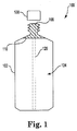
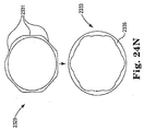
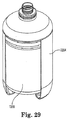
図1は、本開示の実質的に剛性の圧潰可能ライナー100の一実施形態の断面図を例示する。ライナー100は、実質的に剛性のライナー壁102と、内部空洞104と、口部106とを含んでもよい。
FIG. 1 illustrates a cross-sectional view of one embodiment of a substantially rigid
ライナー壁102は、概して、従来の圧潰可能ライナーベースのシステムにおけるライナーより厚くてもよい。ライナー壁102の厚さおよび/またはライナーを構成する膜の組成は、ライナー100の剛性および強度を増加させる。剛性のため、一実施形態では、図1に示されるように、ライナー100は、自立し、従来の剛性壁容器、例えば、ガラス瓶と同様に使用されてもよい。別の実施形態では、ライナー100は、充填、運搬、および保管の間、自立してもよい。すなわち、外側容器は、従来の圧潰可能ライナーベースのシステムにおけるライナーと同様に、ライナーの支持のために必要ではない。一実施形態では、圧力容器は、化学薬品送達の間に、ライナー100から液体を圧力分配するときに、使用されてもよい。さらなる実施形態では、ライナー100は、自立容器システムであってもよい。そのような実施形態は、外側容器と関連付けられたコストを実質的に排除することによって、容器システムの全体的コストを削減することができる。加えて、従来の圧潰可能ライナーベースのシステムにおいて、ライナーおよび外側容器は両方とも、一般的には、再使用不可能であり、廃棄される必要がある。本開示の種々の実施形態では、外側容器が必要ないので、ライナーのみが廃棄され、廃棄物が実質的に低減または最小にされることができる。一実施形態では、ライナー壁102は、約0.05mmから約3mmまでの厚さ、望ましくは、約0.2mmから約1mmまでの厚さであってもよい。しかしながら、厚さは、ライナーの容積に応じて、変動してもよい。概して、ライナー100は、実質的に、ピンホールの発生を低減または排除するために十分な厚さおよび剛性であることができる。
The
前述のように、ライナーを構成する膜の組成ならびにライナー壁102の厚さは両方とも、ライナー100に剛性を提供することができる。厚さは、規定量の圧力または真空が、ライナー100に印加されると、ライナー壁102が、内部空洞104内から液体を分配するように圧潰可能であるように選択される。一実施形態では、ライナー100の分配能力は、ライナー壁102に対して選択された厚さに基づいて制御されてもよい。すなわち、ライナー壁102が厚いほど、内部空洞104内から液体を完全に分配するために印加される必要がある圧力が大きくなる。さらなる実施形態では、ライナー100は、最初、出荷空間を節約するために、圧潰または折畳み状態で出荷され、1回の出荷において、受取人、例えば、化学薬品供給者により多くのライナー100を出荷可能にしてもよい。ライナー100は、続いて、前述の種々の液体または製品のいずれかによって充填され得る。
As mentioned above, both the composition of the membrane that makes up the liner and the thickness of the
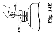
ライナー口部106は、概して剛性であって、いくつかの実施形態では、ライナー壁102より剛性であってもよい。口部106は、口部106が、相補的にネジ切りされたキャップ108を受容し得るように、ネジ山が付けられてもよく、またはネジ山付き嵌合部ポートを含んでもよい。差し込みピン、スナップ嵌合等、任意の他の好適な接続機構が、ネジ山の代わりに、またはそれに加えて使用されてもよい。いくつかの実施形態では、ライナー口部106は、ライナー壁102よりも剛性であり得るので、ライナー口部近傍の領域は、分配の間に、圧力が印加されたときに、ライナー壁102ほど圧潰され得ない。したがって、いくつかの実施形態では、ライナー内の内容物の圧力分配の間、液体は、ライナー口部近傍の領域が完全に圧潰されない死空間内に捕捉され得る。故に、いくつかの実施形態では、圧力分配システムおよび出力ラインの対応するコネクタと接続するためのコネクタ110または接続手段は、実質的に、口部近傍のライナーの概して剛性領域を貫通または充填してもよい。すなわち、コネクタ110は、液体が、圧力分配の間、捕捉されないように、実質的に、死空間を充填し、それによって、死空間の無駄を低減または排除してもよい。コネクタ110は、いくつかの実施形態では、プラスチック等の実質的に剛性の材料から製造されてもよい。
The
さらなる実施形態では、ライナー100は、ライナー100からの流体流出点としての役割を果たす、その下側または遠位端に開口を有する内部の中空浸漬管120(図1では、破線で例示される)を具備してもよい。中空浸漬管120は、コネクタ110と一体型またはそれと別個であってもよい。この点において、ライナー100内の内容物は、浸漬管120を介して、ライナー100から直接受容されてもよい。図1は、随意の浸漬管120を具備し得る、ライナーを例示するが、本明細書に説明される種々の実施形態によるライナー100は、多くの場合、好ましくは、浸漬管を欠いている。浸漬管120の使用を含む、ライナー100のいくつかの実施形態では、浸漬管120はまた、ライナー100内の内容物をポンプ分配するために使用されてもよい。
In a further embodiment, the
ライナー100は、概して平滑な外側表面を有する比較的に単純な設計を有してもよく、またはライナー100は、例えば、限定されないが、プリーツ、リッジ、くぼみ、突出、および/または他のタイプの形態の特徴を含む比較的に複雑な設計を有してもよい。一実施形態では、例えば、ライナー100は、閉塞を防止するようにテクスチャ加工されてもよく、これは、他の実施形態とともに、本明細書で論じられる。すなわち、ライナー100は、ライナー内に液体を捕捉し、液体が適切に分配されることを妨害するであろうように、ライナーがその上に圧潰しないよう防止するようにテクスチャ加工されてもよい。
The
いくつかの実施形態では、ライナー100は、プラスチック、ナイロン、EVOH、ポリオレフィン、あるいは他の天然または合成ポリマーを含む、1つ以上のポリマーを使用して製造されてもよい。さらなる実施形態では、ライナー100は、テレフタル酸ポリエチレン(PET)、ポリエチレンナフタレート(PEN)、ポリ(ブチレン2,6−ナフタレート)(PBN)、ポリエチレン(PE)、鎖状低密度ポリエチレン(LLDPE)、低密度ポリエチレン(LDPE)、中密度ポリエチレン(MDPE)、高密度ポリエチレン(HDPE)、および/またはポリプロピレン(PP)を使用して製造されてもよい。いくつかの実施形態では、選択される材料または複数の材料およびその材料またはそれらの材料の厚さは、ライナー100の剛性を決定し得る。
In some embodiments, the
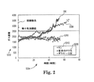
例えば、PENを使用して作製されるライナーは、より低い浸透性を有し、したがって、ライナー100の外側からのガスをライナー壁102にほとんど浸透させず、ライナー100内に保管される液体を汚染させ得ない。概して、例えば、圧力分配の間、ライナー壁を通して、ライナーの内容物中へのガスの浸透量は、ライナーが作製される材料のタイプおよび/またはライナーの厚さに依存し得る。いくつかの実施形態では、例えば、PENの使用は、従来のライナーと比較して、生じ得る浸透量を低下させ、ある場合には、有意に低下させ得る。実施例として、PENを使用する、本開示のいくつかの実施形態では、窒素(N2)の浸透率(cm3/(m2日)単位で測定)は、従来の器具の検出能を下回る、すなわち、1cm3/(m2日)を下回り得る。これは、概して、x軸5304上の時間期間にわたるy軸5302のガス捕捉量を示す図2において見られ得る。図から分かるように、ガス捕捉量は、従来の剛性ガラス容器5306および従来のPTFE容器5308の両方に対して、経時的に有意に上昇する。しかしながら、ガス捕捉量は、例えば、PENから成り得る本開示5310のいくつかの剛性圧潰可能ライナーに対しては、経時的に、比較的に安定した状態のままである。
For example, a liner made using PEN has a lower permeability, and therefore hardly penetrates gas from the outside of the
例えば、PEN、PET、またはPBNから成る、本開示のライナーを使用する別の利点として、そのようなライナーは、実質的に、そうでなければ、ライナーの内容物を汚染し得る抽出可能有機化合物の量を抑止または制限し得ることを挙げることができる。例えば、本開示のライナーの抽出可能有機化合物の解析的分析は、少なくとも従来のPTFEライナーに匹敵し、ある場合には、より良好であり得る。ある場合には、本開示の実施形態の内容物中に見出される抽出可能有機体化合物の割合は、約0.0001%未満と低くあり得る。同様に、微量金属抽出可能物は、全微量金属に対して約5ppb未満および個々の微量金属あたり約1ppb未満、好ましくは、いくつかの実施形態では、全金属に対して1ppb未満、および個々の微量金属に対して0.5ppb未満に維持され得る。有機炭素の総量は、本開示のいくつかの実施形態では、同様に、例えば、約平均20ppb以下に維持され得る。他の実施形態では、有機炭素の総量は、約30ppb未満に維持され得る。加えて、本開示のいくつかの実施形態では、ライナーの内容物中に存在するサイズ0.15ミクロン以上の粒子数は、ミリリットルあたり約15粒子未満、例えば、いくつかの実施形態では、ミリリットルあたり約10粒子未満に制限され得る。 As another advantage of using a liner of the present disclosure, for example consisting of PEN, PET, or PBN, such a liner is substantially an extractable organic compound that can otherwise contaminate the contents of the liner. It can be mentioned that the amount of can be suppressed or limited. For example, the analytical analysis of the extractable organic compounds of the liner of the present disclosure is at least comparable to conventional PTFE liners and may be better in some cases. In some cases, the percentage of extractable organic compounds found in the contents of embodiments of the present disclosure can be as low as less than about 0.0001%. Similarly, trace metal extractables are less than about 5 ppb per total trace metal and less than about 1 ppb per individual trace metal, preferably in some embodiments, less than 1 ppb per total metal, and individual It can be kept below 0.5 ppb for trace metals. The total amount of organic carbon can similarly be maintained, for example, about 20 ppb or less in some embodiments of the present disclosure. In other embodiments, the total amount of organic carbon can be maintained at less than about 30 ppb. In addition, in some embodiments of the present disclosure, the number of particles of size 0.15 microns or greater present in the liner content is less than about 15 particles per milliliter, for example, in some embodiments, per milliliter. It can be limited to less than about 10 particles.
PE、LLDPE、LDPE、MDPE、HDPE、および/またはPPを使用して作製されるライナーはまた、約2000L以下の液体の保管等、より大型の保管および分配システムに好適であり得る。 Liners made using PE, LLDPE, LDPE, MDPE, HDPE, and / or PP may also be suitable for larger storage and distribution systems, such as storage of about 2000 L or less of liquid.
この見出し下で論じられた実質的に剛性の圧潰可能ライナーに加え、代替実施形態では、PEN、PET、またはPBN、および随意に、任意の好適な混合物またはコポリマーの混合物を使用して、そのような剛性ライナーが、例えば、半導体産業に導入され、高純度液体と併用され得るように、前述の剛性壁容器と同様に、実質的に剛性のライナーを作製してもよい。PEN、PET、またはPBNを備えるそのようなライナーは、他のプラスチック容器と比較して、化学適合性を改善し、ガラス瓶と比較して、使用がより安全であり、それによって、一般的には、従来の剛性壁容器向けの産業においても使用可能にする。 In addition to the substantially rigid collapsible liner discussed under this heading, in alternative embodiments, such as using PEN, PET, or PBN, and optionally any suitable mixture or mixture of copolymers, A substantially rigid liner may be made, similar to the rigid wall container described above, such that a rigid liner can be introduced into the semiconductor industry and used with high purity liquids, for example. Such liners with PEN, PET, or PBN have improved chemical compatibility compared to other plastic containers and are safer to use compared to glass bottles, thereby generally It can also be used in the industry for conventional rigid wall containers.
いくつかの実施形態における本開示のPENライナーは、例えば、単回使用のために設計されてもよい。そのようなライナーは、ガラスボトルに関連し得る、所有権、出荷、衛生等のコストを含む全要因を考慮したとき、ガラス瓶より全体的なコストが低くなり得るので、先行技術のガラス瓶の有利な代替となり得る。さらに、PENライナーは、公知のように、ガラスは破損する可能性があり、ガラスの破損は、ボトル内の材料の汚染または紛失をもたらすだけでなく、安全性の問題も生じ得るので、ガラスより有利となり得る。対照的に、本開示のPENライナーは、破損に強くなり得る。いくつかの実施形態では、PENライナーは、オーバーパックを使用しなくてもよい独立型ライナーであってもよい。他の実施形態では、オーバーパックは、ライナーと併用されてもよい。いくつかの実施形態では、PENライナーは、ライナーの内容物の分配能力を向上させることを助長するサンプを含んでもよく、サンプは、以下に詳細に説明され、PENの実施形態において、実質的に同様の方法で使用されるであろう。いくつかの実施形態におけるPENライナーの分配は、ポンプ分配または圧力分配の両方を含んでもよい。しかしながら、いくつかの実施形態では、PENライナは、概して、非圧潰可能であり得るので、圧力分配は、本明細書に記載される他の実施形態の場合であり得るようなライナーの外部壁に対して圧力を加えるのとは対照的に、ライナーの内容物に直接圧力を加えてもよい。いくつかの実施形態では、PENライナーは、二酸化炭素排出を削減し得る。PENライナーの実施形態は、本開示で説明された他のライナーと実質的に同様な方法で使用され得る。 The PEN liner of the present disclosure in some embodiments may be designed for single use, for example. Such liners are advantageous over prior art glass bottles because they can be less costly than glass bottles when considering all the factors that can be associated with glass bottles, including cost of ownership, shipping, hygiene, etc. Can be an alternative. In addition, PEN liners, as is well known, can break glass, which not only leads to contamination or loss of material in the bottle, but can also cause safety issues, so Can be advantageous. In contrast, the PEN liner of the present disclosure can be resistant to breakage. In some embodiments, the PEN liner may be a stand alone liner that may not use an overpack. In other embodiments, the overpack may be used in conjunction with a liner. In some embodiments, the PEN liner may include a sump that assists in improving the ability to distribute the contents of the liner, the sump being described in detail below, and in a PEN embodiment, substantially It will be used in a similar manner. Dispensing the PEN liner in some embodiments may include both pump dispensing or pressure dispensing. However, in some embodiments, the PEN liner may generally be non-collapsible so that the pressure distribution is on the outer wall of the liner as may be the case with other embodiments described herein. In contrast to applying pressure to the liner, pressure may be applied directly to the contents of the liner. In some embodiments, the PEN liner may reduce carbon dioxide emissions. PEN liner embodiments may be used in a manner substantially similar to other liners described in this disclosure.
代替実施形態では、ライナー100は、限定されないが、ポリクロロトリフルオロエチレン(PCTFE)、ポリテトラフルオロエチレン(PTFE)、フッ素化エチレンプロピレン(FEP)、およびパーフルオロアルコキシ(PFA)等のフッ素ポリマーを使用して製造されてもよい。いくつかの実施形態では、ライナー100は、複数の層を備えてもよい。例えば、ある実施形態では、ライナー100は、内部表面層、コア層、および外側層、または任意の他の好適な数の層を含んでもよい。複数の層は、1つ以上の異なるポリマーまたは他の好適な材料を備えてもよい。例えば、内部表面層は、フッ素ポリマー(例えば、PCTFE、PTFE、FEP、PFA等)を使用して製造されてもよく、コア層は、ナイロン、EVOH、ポリエチレンナフタレート(PEN)、PCTFE等の材料を使用して製造されたガス障壁層であってもよい。外側層もまた、任意の種々の好適な材料を使用して製造されてもよく、内部表面層およびコア層のために選択された材料に依存してもよい。本明細書に説明される実質的に剛性のライナーの種々の実施形態は、本明細書に開示される材料の任意の好適な組み合わせから製造さてもよいことができるが認識される。
In an alternative embodiment, the
さらなる代替実施形態では、本開示のポリマーライナーは、金属外側層、例えば、限定されないが、AL(アルミニウム)、鋼、被覆鋼、ステンレス鋼、Ni(ニッケル)、Cu(銅)、Mo(モリブデン、W(タングステン)、クロム銅の二重層、チタン銅の二重層、あるいは任意の他の好適な金属材料または材料の組み合わせを使用して製造されてもよい。いくつかの実施形態では、金属でコーティングされたライナーは、例えば、TEOS(オルト珪酸テトラエチル)からのSiO2、またはSiCl4(四塩化珪素)、MO(金属有機物)、TiCl4(四塩化チタン)からのTiO2、または他の適切な金属酸化材料、あるいは任意の他の好適な金属、もしくはそれらのいくつかの組み合わせ保護誘電体で上塗りされてもよい。金属ライナーは、ガスに対して実質的に不浸透性となり、したがって、内容物の酸化および/または加水分解を低減し、ライナー内に含有される物質の純度を維持し得るので、金属ライナーは、超高純度物質を含む物質の保管および出荷に有利となり得る。金属の不浸透性により、本実施形態のライナーは、ピンホールまたは溶接割れが実質的になくなり得、非常に強固で一貫した充填容積を有し得る。 In a further alternative embodiment, the polymer liner of the present disclosure is a metal outer layer, such as, but not limited to, AL (aluminum), steel, coated steel, stainless steel, Ni (nickel), Cu (copper), Mo (molybdenum, W (tungsten), chromium copper bilayer, titanium copper bilayer, or any other suitable metal material or combination of materials may be used, in some embodiments, coated with metal For example, SiO 2 from TEOS (tetraethyl orthosilicate), or TiO 2 from SiCl 4 (silicon tetrachloride), MO (metal organics), TiCl 4 (titanium tetrachloride), or other suitable It may be overcoated with a metal oxide material, or any other suitable metal, or some combination thereof protective dielectric. The metal liner can be substantially impermeable to gas, thus reducing oxidation and / or hydrolysis of the contents and maintaining the purity of the material contained within the liner. Because of the impervious nature of the metal, the liner of this embodiment can be substantially free of pinholes or weld cracks and is very strong and consistently filled. It can have a volume.
なおも別の実施形態では、本開示のライナーは、金属容器、例えば、限定されないが、アルミニウム、ニッケル、ステンレス鋼、薄肉の鋼、あるいは任意の他の好適な金属材料または材料組み合わせを使用して、製造されてもよい。いくつかの実施形態では、これらの金属容器は、高純度化学薬品と金属壁との相互作用を低減するために、内部表面が不活性膜でコーティグされる。膜は、化学薬品の相互作用および金属製容器内の化学薬品の劣化を低減するために特に選択された不活性金属、金属酸化物、金属窒化物、または金属炭化物であってもよい。別の実施形態では、金属容器は、ガラス、プラスチック、SiO2金属、あるいは任意の他の好適な材料または材料の組み合わせでコーティングされる内部表面を有してもよい。金属の剛性により、本実施形態のライナーは、ピンホールまたは溶接割れが実質的になくなり得り、非常に強固で一貫した充填容積を有し得る。 In yet another embodiment, the liner of the present disclosure uses a metal container, such as, but not limited to, aluminum, nickel, stainless steel, thin steel, or any other suitable metal material or material combination. May be manufactured. In some embodiments, these metal containers are coated with an inert film on the inner surface to reduce the interaction between high purity chemicals and metal walls. The membrane may be an inert metal, metal oxide, metal nitride, or metal carbide specifically selected to reduce chemical interactions and chemical degradation within the metal container. In another embodiment, the metal container may have an internal surface that is coated with glass, plastic, SiO 2 metal, or any other suitable material or combination of materials. Due to the rigidity of the metal, the liner of this embodiment can be substantially free of pinholes or weld cracks and can have a very strong and consistent fill volume.
しかしながら、従来、金属缶は、使用することが高価となってきていた。例えば、金属製容器のコストが容器に保管された物質のコストよりも高くなることが頻繁にあり得る。故に、コスト効率を良くするために、そのような金属製容器は、概して、繰り返し使用され、ひいては、再使用のために容器を返送し、再充填の前に容器を適切に洗浄することが要求される。容器を返送し、再使用のために容器を洗浄することは、時間の浪費になり得るとともに、高いコストになり得る。しかしながら、本開示のいくつかの実施形態では、剛性圧潰可能金属容器は、例えば、先行技術金属容器と比較して、比較的薄い金属ライナーの壁を製造することで、コスト効率的単回使用のために製造され得る。例えば、いくつかの実施形態では、ライナー壁は、0.1から3.0mmまでの厚さであってもよい。より好ましくは、壁は、いくつかの実施形態では、0.6から2mmまでの厚さであってもよい。この壁の厚さによって、本開示の金属ライナーが、実質的に剛性であるが、圧力下で圧潰可能となり得る。金属ライナーは、概して、大きな容積、例えば、いくつかの実施形態では、約2000Lまでを保持するために定寸されてもよい一方、他の実施形態では、金属ライナーは、約200L以下を保持するように定寸されてもよい。 However, conventionally, metal cans have become expensive to use. For example, the cost of a metal container can often be higher than the cost of the material stored in the container. Therefore, in order to be cost effective, such metal containers are generally used repeatedly, thus requiring the containers to be returned for reuse and properly cleaned before refilling. Is done. Returning the container and cleaning the container for reuse can be time consuming and costly. However, in some embodiments of the present disclosure, a rigid collapsible metal container is cost effective single use, for example, by producing a relatively thin metal liner wall compared to prior art metal containers. Can be manufactured for. For example, in some embodiments, the liner wall may be 0.1 to 3.0 mm thick. More preferably, the wall may be 0.6 to 2 mm thick in some embodiments. This wall thickness may allow the metal liner of the present disclosure to be substantially rigid but to be crushed under pressure. The metal liner may generally be sized to hold a large volume, eg, up to about 2000 L in some embodiments, while in other embodiments, the metal liner holds about 200 L or less. It may be sized as follows.
別の実施形態では、金属でコーティングされ得る、プラスチックライナーが、提供されてもよい。例えば、ライナーは、PP、PE、PET、PEN、HDPE、または任意の他の好適なポリマー、あるいは前述のようなポリマーの組み合わせ等のポリマーから形成されてもよい。ライナーの外側は、限定されないが、アルミニウム等で金属化されてもよい。いくつかの実施形態では、金属は、限定されないが、化学蒸着等、蒸着によって容器壁に適用されてもよい。任意の好適な金属が、本実施形態によるポリマーライナーの外部を金属化するために使用されてもよいことが認識されるであろう。ライナーは、例えば、めっき、電気めっき、スプレー等、任意の好適な方法によって金属化されてもよい。ライナーの外部を金属化することにより、ガスの浸透性の影響が実質的に低減または排除され得る。金属コーティングによってもたらされる不浸透性により、本実施形態のライナーは、ピンホールまたは溶接割れが実質的になくなり得、非常に強固で一貫した充填容積を有し得る。前述のライナーと同様に、このタイプの金属コーティングされたライナーはまた、いくつかの実施形態では、約2000Lまで保持するように定寸されてもよい一方、他の実施形態は、約200L以下を保持するように定寸されてもよい。本明細書に説明される、金属ライナーおよび金属コーティングされたライナーは、折り目、プリーツ、取っ手、サンプ、ならびに/あるいは他の実施形態を参照して、本明細書に説明される任意の他のライナー構成および/または特徴を含んでもよい。 In another embodiment, a plastic liner that can be coated with metal may be provided. For example, the liner may be formed from a polymer such as PP, PE, PET, PEN, HDPE, or any other suitable polymer, or a combination of polymers as described above. The outer side of the liner is not limited, but may be metallized with aluminum or the like. In some embodiments, the metal may be applied to the container wall by vapor deposition, such as but not limited to chemical vapor deposition. It will be appreciated that any suitable metal may be used to metallize the exterior of the polymer liner according to this embodiment. The liner may be metallized by any suitable method such as plating, electroplating, spraying, etc. By metallizing the exterior of the liner, the gas permeability effect can be substantially reduced or eliminated. Due to the impermeability provided by the metal coating, the liner of this embodiment can be substantially free of pinholes or weld cracks and can have a very strong and consistent fill volume. Similar to the liners described above, this type of metal coated liner may also be sized to hold up to about 2000L in some embodiments, while other embodiments have about 200L or less. It may be sized to hold. The metal liners and metal-coated liners described herein can be folds, pleats, handles, sumps, and / or any other liner described herein with reference to other embodiments. Configurations and / or features may be included.
いくつかの実施形態では、本開示のライナーは、例えば、エポキシアミンコーティング等の障壁増強コーティングでコーティングされてもよい。しかしながら、他の好適なコーティングポリマーまたはポリマーの混合物が、障壁増強コーティングとして使用されてもよいことが認識される。ライナーがPETまたは他のポリマー材料から構成される場合、コーティングは特に有利となり得るが、しかしながら、コーティングは本開示で熟考されたライナーのうちのいずれにも適用されてもよい。エポキシアミンコーティングの適用により、ガスの浸透性が二方向において低減し得る、すなわち、コーティングは、ライナーに入り込む可能性があるガスの量とともに、ライナーから出る可能性があるガスの量を低減し得る。コーティングの適用はまた、ライナーおよびその内容物の貯蔵寿命も増加し得る。さらに、障壁増強コーティングの適用は、酸素または水分の透過性を低減し得、より広範囲の材料、例えば、限定されないが、没食子酸洗浄剤および/またはCVD前駆体物質等、空気反応性を示す液体をライナーに保管することを可能にし得る。 In some embodiments, the liner of the present disclosure may be coated with a barrier enhancing coating, such as, for example, an epoxyamine coating. However, it will be appreciated that other suitable coating polymers or mixtures of polymers may be used as the barrier enhancing coating. The coating can be particularly advantageous when the liner is composed of PET or other polymeric material, however, the coating may be applied to any of the liners contemplated in this disclosure. Application of an epoxy amine coating can reduce gas permeability in two directions, ie, the coating can reduce the amount of gas that can exit the liner as well as the amount of gas that can enter the liner. . The application of the coating can also increase the shelf life of the liner and its contents. In addition, the application of barrier enhancing coatings can reduce oxygen or moisture permeability, and a wider range of materials, such as, but not limited to, liquids that exhibit air reactivity, such as gallic acid cleaners and / or CVD precursor materials. Can be stored in the liner.
コーティングは、折畳みに先立って、またはライナーが完全に組み立てられた後に、バッグ上にスプレーされてもよい。コーティングは、ライナーの内部および/または外部に適用されてもよく、あるいは複数の層を有する実施形態では、コーティングは、ライナーの1つまたは全層の片側もしくは両側に適用されてもよいことを理解されるであろう。コーティングは、所望の貯蔵寿命に応じて、可変厚で適用されてもよく、例えば、コーティングが厚いほど、貯蔵寿命は長くなる。しかしながら、障壁増強コーティングは、任意の好適な厚さで適用されてもよく、所望の用途に応じて、様々な時間で硬化し得ることが認識されるであろう。さらに、障壁膜の架橋密度および障壁膜の表面接着力は、所望の障壁保護の程度に応じて、変動し得る。概して、ライナー表面は、コーティングの適用等によって、化学的に、物理的に、電気化学的に、または静電気的に、修正され、ライナーの障壁品質を向上させてもよい。いくつかの実施形態では、障壁増強材料は、概して、図3のフロー図に例示されるように、ライナーに適用されてもよい。1つのステップ202では、コーティング材料を受容するための調製において、表面を洗浄するためにイオン化された空気をライナー上に吹き付けることに、ファンが用いられ得る。一実施形態では、ステップ204に示されるように、次いで、電荷が印加されてもよい。障壁増強材料は、次いで、例えば、限定されないが、静電スプレーガン206を使用して、ライナーに適用されてもよい。チャックは、ライナーがコーティング適用領域を通過するすることに伴って、ライナーを回転させ、均一なコーティングの適用が確保され得る。いかなる過剰スプレーも回収され、廃棄され得る。コーティングされたライナーは、次いで、硬化炉208で硬化され得る。別の実施形態では、障壁増強材料は、コーティングとは対照的に、別のライナー層内に、またはそのようなものとして提供されてもよい。
The coating may be sprayed onto the bag prior to folding or after the liner is fully assembled. It will be appreciated that the coating may be applied to the interior and / or exterior of the liner, or in embodiments having multiple layers, the coating may be applied to one or both sides of one or all layers of the liner. Will be done. The coating may be applied in variable thickness depending on the desired shelf life, for example, the thicker the coating, the longer the shelf life. However, it will be appreciated that the barrier enhancing coating may be applied at any suitable thickness and may be cured at various times depending on the desired application. Furthermore, the crosslink density of the barrier film and the surface adhesion of the barrier film can vary depending on the desired degree of barrier protection. Generally, the liner surface may be modified chemically, physically, electrochemically, or electrostatically, such as by application of a coating, to improve the liner barrier quality. In some embodiments, the barrier enhancing material may be applied to the liner, generally as illustrated in the flow diagram of FIG. In one
本開示のライナーは、いくつかの有利な形状をとり得る。図4から分かるように、一実施形態では、剛性圧潰可能ライナー320は、ライナーの底部が丸みを帯びているか、またはボウル形状322となるように構成されてもよい。そのような実施形態では、丸みの程度は、変動し得る。底部表面の丸みは、いくつかの実施形態においては、ライナー320が、依然として、自立し得るようなものであってもよい。さらに別の実施形態では、丸みは、ライナーが、外側容器、オーバーパック、チャイム、または外筒と最適に併用され得るような程度であってもよい。底面の丸みは、例えば、浸漬管をライナーの底部に適切に指向させることを補助し得るので、丸い底部を有するライナーの実施形態は、例えば、ポンプ分配用途において化学的利用の向上に役立ち得る。そのような実施形態は、例えば、不透明であるライナーについて特に有用であり、化学的利用および浸漬管整列の改善にも役立ち得る。
The liner of the present disclosure can take several advantageous shapes. As can be seen from FIG. 4, in one embodiment, the rigid
図5に示されるように、ライナーの別の実施形態では、剛性圧潰可能ライナー402は、分配能力向上を補助し得るサンプ406を含んでもよい。いくつかの実施形態では、ライナー402は、オーバーパック404内に載置されてもよい。サンプ406は、サンプ406を形成する削除部またはカップ408を画定するライナーの底部における実質的に剛性の材料の領域であってもよい。図5に見られるように、削除部領域408は、ライナー402内の液体を削除部領域408に流し込み得る。ライナー402に挿入され得る浸漬管410は、次いで、ライナー内の液体を実質的に全部分配するために使用され、したがって、指向サンプ406を有しない先行技術ライナーにおけるよりも多くの液体量を分配可能にし得る。サンプは、いくつかの実施形態では、ライナーと同じ材料で作られてもよく、またはサンプは、例えば、別のタイプのプラスチック等、別の好適な材料から作製されてもよい。サンプを有するライナーの使用は、圧潰し得ないか、または完全に圧潰し得ない、ライナーとの併用に特に有利となり得る。
As shown in FIG. 5, in another embodiment of the liner, the rigid
ライナー100は、図1に示されるように、較的単純な設計を有していてもよいため、ライナー壁は、いくつかの実施形態では、実質的に剛性のライナー壁102に殆どまたは実質的に折り目を備えていなくてもよい。図6に示される一実施形態では、例えば、ライナー500は、従来の水またはソーダ瓶と同様に成形されてもよい。したがって、本開示の種々の実施形態の付加的利点として、固定充填容積が挙げられる。すなわち、ライナー100は、具体的容積のために設計することができ、実質的に剛性のライナー壁102には殆どまたは実質的に折り目がなくなり得るので、ライナー100が、特定の容積で充填されるとき、溢流は実質的に生じないはずである。上述したように、そのようなライナー100に保管された液体は、一般的には、非常に高価であり、例えば、約$2,500/L以上であり得る。したがって、溢流量のわずかな低減さえも望ましくあり得る。加えて、ライナー内に捕捉されたガス容積は、ライナーが実質に剛性であり、概して、充填に先立ってライナー内にガス捕捉場所をもたらすアンダーカットまたは折り目が存在しない場合に、最小となり得る。
Because the
さらに、ライナーは、内部空洞部内から液体を分配する能力を補助するように成形されてもよい。図7に例示される一実施形態では、ライナー600は、ライナー600の剛性領域、例えば、ライナー壁602から口部606への遷移部近傍の領域を制限することができる、折り目またはくぼみ610を含んでもよい。折り目610は、ライナー内に鋳造されてもよく、または鋳造プロセス後に追加されてもよい。折り目610は、ライナー600の圧潰または折畳みパターンを制御するように設計されてもよい。一実施形態では、ライナー600は、口部606の近傍に、2つまたは4つの折り目を含んでもよい。しかしながら、折り目610は、ライナー壁602の任意の好適な場所に設置されてもよく、ライナー600の圧潰または折畳みパターンを制御し、圧潰の間、ライナー600から流出され得る、粒子の数を低減または最小にするように好適に構成されてもよいことが認識される。折り目610は、ライナー600の完全または概して完全圧潰に応じて、結果として生じる折り目線の数および/またはライナー内のガス捕捉場所を低減または最小にするように構成されてもよい。
Further, the liner may be shaped to assist in the ability to dispense liquid from within the internal cavity. In one embodiment illustrated in FIG. 7, the
図8A−8Dに例示される別の実施形態では、実質的に剛性の圧潰可能ライナー700は、概して、ライナー700の垂直方向距離に延在する、ある場合には、ライナー700の首部702から底部まで、実質的に、ライナー700の垂直方向距離全体に延在する、複数のプリーツ704を含んでもよく、それによって、ライナー700内にパネルまたはパネル状構造を形成してもよい。いくつかの実施形態では、ライナー700は、任意の好適な数のプリーツおよびパネルを含んでもよい。より具体的には、収縮または圧潰状態706における、図8Aおよび8Cに見られ得るように、プリーツ付きライナー700は、ライナー700の円周の周りに設置される複数の概して平行またはパターン化プリーツ704を備えてもよい。膨張または拡張状態708における、図8Bおよび8Dに示されるように、ライナー700のプリーツ704は、概して、ライナーが、収縮状態706にあるときのライナーの円周または直径より大きい、円周または直径まで拡張するように、開放されてもよい。いくつかの実施形態では、ライナー700は、概して、収縮状態706では、コンパクトになってもよく、概して、収縮状態におけるライナーのコンパクトサイズは、剛性外側容器内側にライナーを設置することを比較的に容易にし得る。垂直プリーツ704は、充填中のライナーの迅速な膨張と、分配中の迅速な収縮を可能にし得る。いくつかの実施形態では、図8Eに示されるように、首部702は、先行技術ライナーの首部より薄くてもよい。首部を構成する材料は、概して、薄くあり得るため、首部領域は、そうでない場合より可撓性であって、剛性外側容器内への比較的に容易な挿入、より完全な充填、および/またはより完全なライナーからの排出を可能にし得る。プリーツの結果としてのライナー圧潰および/またはライナーの首部を構成する比較的薄い材料により、本実施形態はまた、閉塞を防止し得る。
In another embodiment illustrated in FIGS. 8A-8D, the substantially rigid
図9Aおよび9Bに例示される、さらなる実施形態では、実質的に剛性の圧潰可能ライナー800は、ライナーの首部から底部まで、ライナー800の垂直方向距離に延在するか、ある場合には、ライナーの垂直方向距離全体に実質的に延在し得る複数の非垂直または螺旋プリーツ804を備えてもよい。より具体的には、拡張状態におけるライナーを示す図9Aに見られ得るように、複数のプリーツ804は各々、概して、ライナー800の上部からライナーの底部まで実質的に直線ではなく、代わりに、各プリーツは、概して、プリーツがライナーの上部から底部まで延在するに伴ってライナーの横方向に傾斜、屈曲、湾曲等し得る。複数のプリーツ804は各々、ライナー800の垂直方向距離の周りに実質的に均一な程度の傾斜、屈曲、湾曲等を有し得る。しかしながら、他の実施形態では、複数のプリーツ804は各々、他のプリーツと均一または非均一に、任意の好適な程度においてライナーの周りに傾斜、屈曲、湾曲等を有してもよい。理解され得るように、ライナー800が、図9Bに示されるように、その内容物の排出または分配に応じて圧潰し始めると、複数の螺旋プリーツ804は、概して、ライナーの上部に対して、ライナー底部を捻転させるであろう。この捻転運動は、ライナーの捻転が、ライナーの底部からライナーの上部へとライナー内容物を圧搾することに伴って、より効率的な圧潰および/またはより完全なライナーの内容物の排出を可能にし得る。螺旋プリーツおよび圧潰の間に生じる結果として生じる捻転運動の結果、本実施形態はまた、閉塞を防止し得る。
In a further embodiment illustrated in FIGS. 9A and 9B, the substantially rigid
図10に例示される、さらなる実施形態では、実質的に剛性の圧潰可能ライナー900は、練り歯磨きチューブと同様の方法で成形されてもよく、概して、平坦に圧潰するように構成されてもよい。そのような構成は、圧潰しにくい領域内に捕捉される液体の量を低減または最小にすることを補助することができ、完全にライナーを圧潰するために要求される圧力または真空の量を低減することができる。ライナー900の形状はまた、圧潰の間、そうでなければ襞線に粒子の発生を引き起こし、それによって、ライナー内の液体を汚染し得るライナー900の襞生成を低減し得る。同様に、本開示の実質的に剛性圧潰可能ライナーの多くの実施形態のように、ライナー900の構成は、気泡に対する捕捉点の数を低減または最小にすることができる。そのような実質的に剛性圧潰可能ライナーはまた、例えば、図10に例示される口部906近傍の傾斜部分912等の傾斜部分を含み、分配の開始時、頭隙ガスを円滑に除去することを補助してもよい。概して、「頭隙」という表現は、本明細書で使用されるように、ライナー内に保管される内容物上方において、ライナーの上部まで上昇し得るライナー内のガス空間を示し得る。内容物分配に先立って、頭隙ガスを除去することによって、液体と直接接触するガスは、分配プロセスの間、液体中に溶解されるガスの量が有意に低減または最小にされるように、減少または実質的に排除されることができる。最小溶解ガスを有する液体は、概して、分配系列内で圧力降下を受けた後にガス気泡を放出する傾向が低く、したがって、実質的に、液体分配システムにおけるガス気泡問題を低減または排除する。概して、ライナー内の頭隙は、最初に、ライナーが圧潰を開始し、それによって、ライナーから外に頭隙除去ポートまたは他の好適な出口ポートを通して過剰ガスを強制するように、圧力ポートを介して、ライナーとオーバーパックとの間の環状空間を加圧することによって、除去または低減されてもよい。別の実施形態では、本開示の一実施形態によるライナーは、四角にされた底部ではなく、図4に例示されるように、実質的に丸い底部を有してもよい。
In a further embodiment illustrated in FIG. 10, the substantially rigid
本開示のさらなる実施形態によるライナーは、自立しなくてもよく、なおもさらなる実施形態では、外筒916が、ライナーを支持するために提供されてもよい。外筒916は、側壁920および底部922を含んでもよい。外筒916は、実質的に、ライナー900から遊離していてもよい。すなわち、ライナー900は、取外し可能であってもよく、または外筒916の内部に取外し可能に取着されてもよい。ライナー900は、外筒916に接着接合または別様に接合される必要はない。しかしながら、いくつかの実施形態では、ライナー900は、本開示の精神および範囲から逸脱することなく、外筒916に接着接合されることができる。一実施形態では、外筒916は、概して、犠牲的オーバーパックまたは外側容器とみなされ得る。外筒916は、任意の好適な高さであることができ、いくつかの実施形態では、外筒916は、ライナー900と実質的に同一の高さ以上であり得る。外筒916がそのような高さである実施形態では、取っ手918は、外筒916およびライナー900の運搬を補助するために提供されてもよい。外筒916は、プラスチック、ナイロン、EVOH、ポリオレフィン、あるいは他の天然または合成ポリマーを含む1つ以上のポリマーを使用して作製されてもよく、使い捨てであってもよい。他の実施形態では、外筒916は、再利用可能であってもよい。
The liner according to further embodiments of the present disclosure may not be self-supporting, and in still further embodiments, an
いくつかの実施形態では、ライナーは、例えば、相補的ネジ切り、スナップ嵌合、または任意の他の好適な手段によって、ライナーの嵌合部およびオーバーパックの口部または首部において、オーバーパックに取り外し可能に接続されてもよい。ライナーは、いくつかの実施形態では、ライナーをオーバーパックから捻転または解巻することによって、あるいは他の実施形態では、捻転および引っ張ることによって、またはライナーをオーバーパックから単に引っ張ることによって除去されてもよい。オーバーパックから除去されると、ライナーは、リサイクル、洗浄、滅菌、および再使用されてもよく、または別様に廃棄されてもよい。 In some embodiments, the liner is removed from the overpack at the mating portion of the liner and the mouth or neck of the overpack, for example, by complementary threading, snap-fit, or any other suitable means. It may be connected as possible. The liner may be removed in some embodiments by twisting or unwinding the liner from the overpack, or in other embodiments by twisting and pulling, or simply by pulling the liner from the overpack. Good. Once removed from the overpack, the liner may be recycled, washed, sterilized, and reused, or otherwise discarded.
いくつかの実施形態では、図11A−13Cに示されるようなコネクタは、充填および分配を容易にするとともに、保管中に空気および他の汚染物質からライナーの内容物を保護するために、剛性または剛性圧潰可能ライナーと併用されてもよい。図11Aおよび11Bから分かるように、ライナー1000は、ライナー1000と一体化され得るか、またはライナーに固定して接続され得る首部1002を含んでもよい。首部1002は、保護オーバーキャップ1006の内面の相補的なネジ部と連結するために、外側表面上にネジ部1004を有してもよい。しかしながら、摩擦嵌合、スナップ嵌合等、キャップをライナーの首部および/またはコネクタに取外し可能に取着する任意の好適な方法が、使用されてもよいことが認識されるであろう。コネクタ1008は、ライナー1000の首部1002の内側に嵌合するように構成され得るベース区画1010を含んでもよい。コネクタ1008はまた、コネクタ1008のベース区画1010が、ライナーの首部1002内に設置されると、肩部区画1012が、概して、ライナーの首部1002上縁に当接し、それによって、コネクタ1008とライナー1000との間にシールを生成するように、肩部区画または出っ張り1012を備えてもよい。いくつかの実施形態では、保護キャップ1006は、コネクタ1008と一体化されてもよい。しかしながら、他の実施形態では、保護キャップ1006およびコネクタ1008は、別個の構成要素であってもよく、さらに、保管および/または分配手順のために、相互に取り外し可能に固着されてもよい。
In some embodiments, a connector as shown in FIGS. 11A-13C can be rigid or easy to fill and dispense and protect the liner contents from air and other contaminants during storage. It may be used in combination with a rigid collapsible liner. As can be seen from FIGS. 11A and 11B, the
図11Aに示されるように、一実施形態では、隔壁1016が、瓶1000を密閉し、それによって、瓶1000内に任意の物質を確実に含有し得るコネクタ1008内またはそれに隣接して、設置されてもよい。コネクタ1008はまた、隔壁1016から、ベース1010の垂直方向距離全体を通して延在し、分配に応じて、ライナーの内容物1000をコネクタ1008に通過させる中空管または領域1018を含んでもよい。ライナーの内容物を分配するために、針またはカニューレ1020は、針またはカニューレ1020がライナー1000を密閉する隔壁1016と接触し、それを穿刺し得るように、コネクタ1008および/または保護キャップ1006内の開口部を通して導入されてもよい。さらなる実施形態では、コネクタは、浸漬管またはスタビープローブを備えてもよい。
As shown in FIG. 11A, in one embodiment, a
図11Bに示される別の実施形態では、易壊性ディスク1024が、ライナー内に任意の物質を確実に含有する瓶1000を密閉し得るコネクタ1008のベース内またはそれに隣接して、設置されてもよい。コネクタ1008はまた、易壊性ディスク1024から、ベース1010の垂直方向距離全体を通して延在し、分配時にライナーの内容物をコネクタ1008に通過させる中空管または領域1018を含んでもよい。キャップ1006は、コネクタ、好ましくは、コネクタ1008のベースに固着されてもよい。瓶1000の内容物は、瓶が十分に加圧されると、易壊性ディスク1024が破裂し、ライナーの内容物1000が分配され始め得るように、圧力分配されてもよい。
In another embodiment shown in FIG. 11B, a
図12は、コネクタ本体1104内に鋳造されるポート1110−1116を含み得るコネクタ1102の別の実施形態を示す。ポートは、例えば、液体またはガスをライナーに流入させる液体/ガス入口ポート1110、通気口出口1112、液体出口1114、および/またはライナーの内容物を除去させる分配ポート1116を含んでもよい。
FIG. 12 illustrates another embodiment of a
図13A−13Cは、容器に物質を充填した後にコネクタがどのように密閉され得るかの別の実施形態を示す。図13Aに示されるように、管1204は、コネクタ1202の本体に垂直に嵌入されてもよい。管1204は、熱可塑性樹脂またはガラス等、任意の好適な材料から構成されてもよい。ライナーは、管1204を介して内容物が充填されてもよい。ライナーが充填された後、管1204は、図13Bに示されるように、溶接閉鎖1206または別様に密閉されてもよい。保護キャップ1208は、次いで、図13Cに示されるように、コネクタ1202に取り外し可能に固着されてもよい。本実施形態のコネクタアセンブリは、ライナー用の実質的に漏れ止め閉鎖機構を提供してもよい。加えて、本実施形態の密閉は、前述の密閉実施形態と併用されてもよい。
13A-13C show another embodiment of how the connector can be sealed after filling the container with material. As shown in FIG. 13A, the
いくつかの実施形態では、コード化された係止キャップおよび/またはコネクタが、本開示のライナーおよび/またはオーバーパックの1つ以上の実施形態と併用されてもよい。コード化された係止部は、いくつかの実施形態では、例えば、コルク栓、ネジ蓋、および回転デバイスによって密閉され得る瓶開口部の周囲に取着された外筒を含んでもよい。ネジ込み開口部は、コルク栓に対応する外筒上の場所に形成されてもよく、ネジ蓋は、例えば、瓶のコルク栓を覆い隠すように、外筒のネジ込み開口部内に螺入されてもよい。所与の外形を有する暗号穴が、ネジ蓋上に配置されてもよく、回転デバイスは、概して暗号穴に整列する鍵を伴うその端部に提供されてもよい。ネジ蓋は、回転デバイスの鍵が、ネジ蓋上の暗号穴と完全に整列するときにのみコルク栓を暴露させるように回転させられ得る。そのようなコード化された係止キャップおよび/またはコネクタの実施例、ならびにコード化された係止キャップおよび/またはコネクタの付加的実施形態は、2006年3月3日に出願された中国特許第ZL200620004780.8号(名称「Coded Lock for Identifying a Bottled Medicament」)により詳細に説明されており、参照することによって、全体として本明細書に組み込まれる。別の実施形態では、コード化されたコネクタは、穿孔されたキーコード、RFID(無線周波数識別)チップ、または任意の他の好適な機構または機構の組み合わせを具備し、コネクタと本明細書に説明されるライナーおよび/またはオーバーパックの種々の実施形態との間の誤接続を防止してもよい。 In some embodiments, a coded locking cap and / or connector may be used in conjunction with one or more embodiments of the liner and / or overpack of the present disclosure. The coded lock may in some embodiments include, for example, a cork, a screw cap, and an outer tube attached around a bottle opening that may be sealed by a rotating device. The screw opening may be formed at a location on the outer cylinder corresponding to the cork stopper, and the screw cap is screwed into the screw opening of the outer cylinder, for example, so as to cover the cork stopper of the bottle. May be. A crypto hole having a given profile may be placed on the screw cap and a rotating device may be provided at its end with a key generally aligned with the crypto hole. The screw cap can be rotated to expose the cork only when the key of the rotating device is fully aligned with the crypto hole on the screw cap. Examples of such coded locking caps and / or connectors, as well as additional embodiments of coded locking caps and / or connectors, are disclosed in Chinese Patent No. 3, filed on Mar. 3, 2006. ZL200620004780.8 (named “Coded Lock for Identifying a Bottled Medicine”), which is incorporated herein by reference in its entirety. In another embodiment, the encoded connector comprises a perforated key code, an RFID (Radio Frequency Identification) chip, or any other suitable mechanism or combination of mechanisms, as described herein with the connector. Misconnections between various embodiments of liners and / or overpacks may be prevented.
さらに別の実施形態では、コネクタは、ライナーの内容物の再循環を可能にし得るか、または可能にしてもよく、これは、特に、感圧式または粘性材料の再循環のために有用であり得る。前述のように、本開示の保管および分配システムは、酸、溶媒、基剤、フォトレジスト、ドーパント、無機物、有機物、および生物学的溶液、医薬品、ならびに放射性化学物質の運搬および分配のために使用されてもよい。これらのタイプの材料のうちのいくつかは、分配されていない間、再循環を要求し得、そうでなければ腐敗および使用不可能になり得る。これらの材料のうちのいくつかは、非常に高価であり得るため、内容物が腐敗しないように維持することが望ましくあり得る。故に、一実施形態では、コネクタを使用して、ライナーの内容物を再循環させてもよい。そのようなコネクタの実施形態の詳細な説明は、2011年2月1日出願の米国仮特許出願第61/438,338号(名称「Connectors for Liner−Based Dispense Containers」)に提供されており、参照することによって、全体として本明細書に組み込まれる。 In yet another embodiment, the connector may allow or allow recirculation of the liner contents, which may be particularly useful for pressure sensitive or viscous material recirculation. . As described above, the storage and distribution system of the present disclosure is used for the transport and distribution of acids, solvents, bases, photoresists, dopants, inorganics, organics, and biological solutions, pharmaceuticals, and radioactive chemicals. May be. Some of these types of materials can require recycling while not being dispensed, otherwise they can become spoiled and unusable. Since some of these materials can be very expensive, it may be desirable to keep the contents from decaying. Thus, in one embodiment, a connector may be used to recirculate the contents of the liner. A detailed description of an embodiment of such a connector is provided in US Provisional Patent Application No. 61 / 438,338, filed February 1, 2011 (named “Connectors for Liner-Based Dispense Containers”), Which is incorporated herein by reference in its entirety.
一実施形態では、取っ手が、剛性圧潰可能ライナーおよびオーバーパックシステムとともに含まれてもよい。図14Aに示されるように、剛性圧潰可能ライナー1302は、ライナー1302の首部1306に固着された取っ手1304を有してもよい。ライナー1302は、ライナー首部1306においてライナー1302に接続される取っ手1304の2つの自由端と実質的に同一高さに、オーバーパック1310を囲む縁またはチャイム1312を有する、オーバーパック1310内に挿入されてもよい。取っ手の両端は、実矧ぎ、スナップ嵌合、または取っ手の両端をチャイムに取り外し可能に固着する任意の他の手段を介して、オーバーパック1310のチャイム1312に取着してもよい。そのような実施形態では、ライナー開口部1314を含む、ライナー1302の上部に印加される任意の向きの力が、概して、取っ手に、次いで、チャイム1312およびオーバーパック1310に伝達され、したがって、ライナー1302にかかる応力を低減させ得る。別の実施形態では、取っ手1304の両端はまた、ライナー1302に取着されてもよい。
In one embodiment, a handle may be included with a rigid collapsible liner and overpack system. As shown in FIG. 14A, the rigid
いくつかの実施形態では、図14BおよびCに示されるように、取っ手4842は、ライナーベースのシステム4840を持ち上げるかおよび/または移動させるために使用されてもよい。取っ手4842は、任意の色であってもよく、任意の好適な材料または材料の組み合わせ、例えば、プラスチックから作製されてもよい。図に見られ得るように、いくつかの実施形態では、取っ手4842は、取っ手が水平位置にあるとき、容器4846の円周を越えて延在しないように構成されてもよい。さらなる実施形態では、取っ手4842は、例えば、非使用位置にあるとき、取っ手4842が概して垂直に引っ張られるとき、または別様に、ユーザによる使用時に、概して、真っすぐ伸ばされるように構成され得る1つ以上の隆起領域または拡張領域4854を有してもよい。故に、取っ手4842が、例えば、図48D−Fに示されるように、使用時または搬送位置に設置されるとき、いくつかの実施形態では、取っ手4842は、拡張領域4854が屈することによって、拡張または延伸してもよい。例えば、いくつかの実施形態では、取っ手は、取っ手4842を持ち上げるとき、約1/2から1と1/2インチまでだけ拡張してもよい。他の実施形態では、取っ手は、必要に応じて、より多くまたはより少なく拡張するように構成されてもよい。搬送位置にある間、取っ手が拡張する能力は、有利には、取っ手が、例えば、出荷または保管の間、損傷を受けないように、非使用位置にある間、取っ手が、容器の円周方向寸法内に留まることを可能にし得る。使用時または搬送位置にある間の取っ手の拡張はまた、取っ手に、ある程度キャップおよび/またはコネクタ4850と隙間を空けさせることができる。
In some embodiments, as shown in FIGS. 14B and C, a
図15Aおよび15Bに示されるように、別の実施形態では、剛性圧潰可能ライナー1402は、下部オーバーパック1404および上部オーバーパック1406を備える2つの部分から形成されるオーバーパックと併用されてもよい。図15Aから分かるように、ライナー1402は、最初に下部オーバーパック1404内に挿入されてもよい。上部オーバーパック1406は、次いで、ライナー1402の上部を覆って載置され、図15Bから分かるように、上部オーバーパック1406が、下部オーバーパック1404に接続されるように押下され得る。上部オーバーパック1406は、限定されないが、スナップ嵌合または螺合嵌合等、任意の好適な手段によって、下部オーバーパック1404に取着されてもよい。いくつかの実施形態では、上部オーバーパック1406は、分配に応じて、加圧を使用してライナー1402を圧潰させ得るように、下部オーバーパック1404に密閉されてもよい。密閉は、任意の公知の手段によって達成されてもよい。上部オーバーパック1406は、ライナー1416の首部において、ライナー1402に取着してもよい。上部オーバーパック1406は、1つ以上の取っ手1414を含み、システムの運搬または移動をより容易にしてもよい。本実施形態では、ライナーの閉鎖部1418を含むライナー1402の上部に印加され得る下向き力が、概して、上部オーバーパック1406に、次いで、底部オーバーパック1404に伝達され、それによって、ライナー自体にかかる応力を最小化または低減させ得る。
As shown in FIGS. 15A and 15B, in another embodiment, the rigid
別の実施形態では、剛性圧潰可能ライナー1502は、図16に示されるように、オーバーパック1504内に設置されてもよい。ライナー1502のライナー首部1512は、いくつかの実施形態では、1つ以上の取っ手1508を含み、ライナーの移動をより容易にしてもよい。取っ手1508は、ライナーの首部1512と一体的に構成されてもよく、または任意の公知の手段によって、ライナーに固定して固着されてもよく、例えば、取っ手は、ライナーとともに吹込成形されてもよい。ライナー1502の壁は、他より厚いいくつかの区画1506を有してもよい。これらのより厚い壁区画1506は、垂直方向に増加した厚みをもたらしてもよいが、分配に応じて、ライナー1502が圧潰する能力に干渉しない。これらのより厚い区画1506の厚さは、いくつかの実施形態では、例えば、他のライナー壁区画の約2倍から約10倍まで厚くてもよい。しかしながら、より厚い壁区画は、他の実施形態では、任意の程度の付加的厚さを有し得ることが認識されるであろう。増加した厚みを有するライナー壁の1つ以上の区画が存在してもよく、例えば、いくつかの実施形態では、1つ、2つ、3つ、または4つ、またはそれ以上のそのような区画が存在してもよい。そのような実施形態では、ライナー1502の閉鎖部1510を含む、ライナー1502の上部にかかる任意の下向き力は、概して、ライナー1502のより厚い壁区画1506に、次いで、オーバーパック1504に伝達され、それによって、ライナー1502にかかる応力が低減され得る。
In another embodiment, the rigid
本開示のいくつかの実施形態では、実質的に剛性の圧潰可能ライナーは、ライナー壁の厚さ、ライナーのために使用される材料、および折り目の設計に応じて、90%を超える分配能力、望ましくは、97%を超える分配能力、さらに望ましくは、最大99.9%の分配能力を得られ得る。 In some embodiments of the present disclosure, the substantially rigid collapsible liner has a dispensing capacity of greater than 90%, depending on the liner wall thickness, the material used for the liner, and the fold design, Desirably, a dispensing capacity of greater than 97%, more desirably, a dispensing capacity of up to 99.9% may be obtained.
いくつかの実施形態では、剛性圧潰可能ライナーは、剛性圧潰可能ライナーに1つ以上の「強固な折り目」および/または「事前折り目」あるいは「二次的折り目」を含み得る折り目パターンを含むように構成されてもよい。そのようなライナーは、いくつかの実施形態では、例えば、オーバーパック自体の直径と比較して、比較的小さな直径を伴う開口部を有し得るオーバーパックへのライナーの挿入、またはオーバーパックからのライナーの除去ができ得る、比較的小さな円周方向領域内にそれらが実質的に均一に圧潰させるように形成されてもよい。図17から分かるように、概して、業界で既に使用されている公知のオーバーパックに類似し得るオーバーパック1600は、より大きな直径のオーバーパック1600と比較して、小さい開口部1602を有してもよい。本実施形態の剛性圧潰可能ライナーの使用は、いくつかの理由から、従来の可撓性ライナーの使用と比べて有利となり得る。例えば、従来の可撓性ライナーは、ライナーが、出荷中に動き回るので、ピンホールまたは溶接割れが形成されがちになり得る。トラック、列車、または他の運搬手段が動くことに伴って、オーバーパック内の従来の可撓性ライナーもまた、動き得る。ライナーが動きに曝されるほど、ライナー内に小さな穴が生じることになるリスクが高まる。従来の可撓性ライナーより丈夫な材料で作製される剛性圧潰可能ライナーの使用は、出荷中に溶接割れやピンホールが増大し得るリスクを大幅に低減し得る。従来の可撓性ライナーはまた、充填されるときに襞を形成するという不利点を有し、ライナー中に保持できる材料の量を制限するか、またはライナー内に捕捉されるガスの容積を増加させ得、また、完全な分配を困難または不可能にし得る。従来の可撓性ライナーにおけるそのような襞はまた、出荷中に襞にかかる応力が、襞がない領域と比較して増加され得るので、溶接割れおよび/またはピンホールが発生し得る可能性に寄与し、襞点において、ライナーに小さな裂け目をもたらし得る。本開示のいくつかの実施形態の剛性圧潰可能ライナーは、そのような襞を発生させ得ないが、代わりに、ライナーの折り目線に沿って、所定の容積に拡張し、したがって、材料を保管するためのより大きく、より一貫した内部容積を可能にし得る。襞の欠如はまた、ライナー内の高応力領域を排除し得る。オーバーパック1600と併用時の従来の可撓性ライナーと比べた本開示の種々の実施形態のさらに別の利点は、剛性圧潰可能ライナーが、従来の可撓性ライナーより容易にオーバーパック1600から除去され得ることであり得る。従来の可撓性ライナーが、オーバーパック開口部1602を通してオーバーパック1600から除去されるとき、ライナーの上部が開口部1602を介して引っ張られ、ライナー材料の有意な部分を含有し得る、ライナーの底部をオーバーパック1600の比較的に小さい開口部1602から取り出すことが困難となり得るので、有意な量の分配されない内容物がライナーの底部に蓄積し得る。しかしながら、本実施形態は、ライナー折り目線(以下により詳細に説明される)によって決定された所定の形状に圧潰し得、分配能力の増加とともに、ライナーが、開口部1602を通して引っ張られることに伴って、ライナーの底部に過剰な材料の蓄積を実質的に低減または排除し得る。故に、オーバーパック1600から空のライナーを除去することが実質的により容易になり得る。
In some embodiments, the rigid collapsible liner includes a crease pattern that may include one or more “strong creases” and / or “pre-creases” or “secondary creases” in the rigid collapsible liner. It may be configured. Such a liner, in some embodiments, for example, inserts a liner into or from an overpack that may have an opening with a relatively small diameter compared to the diameter of the overpack itself. They may be formed such that they are substantially uniformly crushed within a relatively small circumferential region where the liner can be removed. As can be seen from FIG. 17, an
図18Aは、ライナー1700が圧潰状態にあるときの、所定の折り目を有するライナー1700の一実施形態の端面図を示す。本実施形態では、ライナー1700は、4アーム設計を有し、端から見ると、圧潰状態において、ライナー1700が4つのアーム1702を有していることを意味する。各アーム1702は、いくつかの実施形態では、概して、同一比率および寸法を有し得る。他の実施形態では、アームは、異なるまたは可変寸法を有し得る。本実施形態のライナーは、浸漬管を伴わずに使用されてもよい。他の実施形態では、ライナーは、浸漬管を含んでもよい。図18Bから分かるように、ライナー1710は、本体1712と、嵌合部1724を含む嵌合部端部1720と、ライナーが、オーバーパックに挿入されると、オーバーパック容器の底部に接触する静止端部1716と、嵌合部端部に最も近傍の本体を嵌合部端部1720に接続する遷移領域1724と、静止端部近傍の本体を静止端部1716に接続する遷移領域1726とを有してもよい。図から分かるように、全折り目は、ライナー1710自体が垂直方向に向けられると、実質的に垂直に配向され得る。垂直折り目線は、気泡がライナー1710の上部まで、折り目線に沿って垂直方向に移動する傾向があり得るので、ライナーの内容物中に存在し得る任意の気泡をより容易に逃散または除去可能にし得る。
FIG. 18A shows an end view of one embodiment of a
4アーム設計によるライナーの本体は、概して、8つの折り目を伴って生成されてもよい。図18Aを再び参照すると最も分かるように、8つの垂直折り目1704は、ライナーの一端からライナーの他端へ延設され、ライナーが圧潰状態にあるとき、ライナーの端部から見ると、概して、4つのアームの星状形状を形成し得る。本実施形態は4つのアーム設計に関して説明および図示されているが、本開示が3つのアーム、5つのアーム、6つのアーム、および任意の他の数のアーム設計も含むことを理解されたい。
The body of the liner with a 4-arm design may generally be produced with 8 folds. As best seen with reference again to FIG. 18A, the eight
図18Bを再び参照すると、嵌合部端部1720上に位置する嵌合部1724は、ライナー1710と一体であってもよい。いくつかの実施形態では、嵌合部1724は、ライナーの残りの部分を構成する材料よりも厚く、また、いくつかの実施形態では、より強い材料から構成されてもよい。嵌合部は、コネクタおよび/またはキャップが、本開示の他の部分に詳細に記載されているように、閉鎖および/または分配のために、ライナー/オーバーパックに取着され得るように、オーバーパック1600内の開口部1602と連結するように構成されてもよい。
Referring back to FIG. 18B, the
ライナー1710の静止端部1716は、できるだけ多くの内容物を保持し、空間の無駄を回避するために、ライナーが充填されるとき、概して、拡張されてもよい。同様に、ライナー1710の静止端部1716は、概して、ライナーの圧潰に応じて、その折り目線に沿って、実質的に精密に圧潰し、オーバーパックからのライナーの容易な除去を確実にするとともに、ほとんど全ての材料がライナー1710から分配され得ることを確実にし得る。
The
図19から分かるように、折り目を有するライナー1802のいくつかの実施形態では、1つ以上の反転位置1806が、ライナーの本体1810とライナーの静止端部1808との間の遷移領域1804の周囲に生成され得る。反転位置1806は、ライナーの分配および/または圧潰を困難にするように外向きに座屈する領域、またはライナーを材料で完全に充填するために、ライナーを実質的に完全に拡張させることを困難にするように内向きに座屈する領域となり得るので、望ましくない可能性がある。
As can be seen from FIG. 19, in some embodiments of the
いくつかの実施形態では、反転位置は、ライナーにおける適切な場所に二次的折り目を含むことによって、制限または概して排除され得る。例えば、図20Aおよび20Bに示されるように、図示されるように、ライナー1906の本体から、ライナーの遷移領域を通して、ライナー1900の静止端部の頂点1908へと延在し得る二次的折り目または事前折り目1904が、ライナーに含まれてもよい。これらの二次的折り目または事前折り目1904は、図19に示されるような反転位置を回避することを補助し得る。図20Bから最も良く分かるように、ライナーが二次的折り目1904または事前折り目によって誘導されるように拡張および圧潰する傾向により、反転位置の形成が回避され得る。
In some embodiments, the flip position can be limited or generally eliminated by including secondary folds at appropriate locations in the liner. For example, as shown in FIGS. 20A and 20B, a secondary fold that can extend from the body of the
同様に、圧潰され、オーバーパック内の開口部内に挿入されるときと、そこから引っ張られるとき、ライナーの円周方向領域をさらに縮小し得る付加的な垂直二次的折り目線が、ライナーに含まれてもよい。これは、開口部2008に挿入されるか、またはそこから引っ張られているライナー2000を示す、図21に見られ得る。図示される実施形態では、二次的折り目2006は、アーム2010上の概して半分の所に配置されており、これにより、ライナー2000のアーム2010が占有する円周領域を二次的折り目2006がない場合に比べて小さくすることが可能である。しかしながら、二次的折り目2006が、アーム2010上の任意の好適な位置に設置されてもよいことが認識されるであろう。
Similarly, the liner includes an additional vertical secondary crease line that can be further collapsed when it is crushed and inserted into an opening in the overpack and pulled from it. May be. This can be seen in FIG. 21, which shows the
いくつかの実施形態では、図22Aに示されるように、ライナー2102の静止端部2106に形成された折り目によって生成されるライナー2102の角部2104は、完全に拡張できない可能性があり、したがって、ライナー2102内に含有され得る材料の量を制限し得る。前述のように、ライナーができるだけ多くの液体を保持できるように、静止端部をできるだけ大きく拡張させることが好ましくあり得る。図22Bから分かるように、本実施形態におけるライナー2122の静止端部2124は、より完全に拡張し得る。これは、一実施形態では、例えば、遷移角2128が35°から55°、好ましくは、例えば、約45°のときに達成され得る。遷移角2128は、ライナー2122の本体2130の実質的な垂線および折り目と、静止端部2124の頂点2136との間に形成される角度となり得る。好ましい約45°の遷移角は、一実施形態では、図22Bに示されるように、静止端部2124がその角度においてより完全に膨張し得るという点で、幾分、「魔法」の角度となり得る。しかしながら、好ましい約45°より大きいまたは小さい遷移角も本開示の精神および範囲の内にあることが認識されるであろう。
In some embodiments, as shown in FIG. 22A, the
いくつかの実施形態では、圧潰状態におけるライナー2200の静止端部2204は、図23Bに示されるように、ライナー2200の本体の内側で圧潰してもよい。静止端部2204は、ライナーの本体の端部とライナーの静止端部の頂点との間の高さが比較的短いとき、このような傾向となり得る。そのようなライナーは、ライナーが充填されているとき、ライナー2200の高さを有利に低減し得る。図23Aに見られ得るように、本実施形態によるライナー2200は、拡張状態において、概して、完全に拡張する静止端部2204を有してもよい。
In some embodiments, the
折り目パターンを有するライナーのいくつかの実施形態では、ライナーの静止端部2210は、図23Cに見られ得るように、実質的に、平坦であるように構成されてもよい。そのような実施形態では、ライナーの上部は、例えば、平坦幾何学形状または先細幾何学形状を含む、任意の好適な構成を有してもよい。実質的に平坦静止端部を伴うライナーの実施形態は、任意の全体的形状を有してもよく、例えば、ライナーは、任意の数の垂直折り目を有してもよく、任意の望ましい円周を有してもよい。加えて、前述の他の実施形態に対して前述のように、折り目を伴うライナーのいくつかの実施形態は、独立型容器として使用されてもよく、オーバーパックの使用を要求しなくてもよい。
In some embodiments of a liner having a crease pattern, the liner's
独立型容器であり得るライナーならびにオーバーパックと併用するためのライナーを含む、ライナーのいくつかの実施形態は、円筒形に近似する幾何学形状を有してもよいが、折り目パターンを有するライナーのさらに他の実施形態として、例えば、長方形角柱により密接に近似する全体的幾何学形状を有するライナー2206が、挙げられ得る。そのような実施形態のライナーは、任意の望ましい構成の静止端部および/または上部端部を含んでもよく、例えば、一端または両端は、実質的に平坦であってもよく、または前述のように、先細幾何学形状を有してもよい。概して、より長方形の幾何学形状を有するライナーは、6つの概して長方形ライナーの充填密度上に重ね合わせられた3つの概して円筒形ライナーの充填密度を示す、図23Dに見られ得るように、ライナーが拡張時、出荷および/または保管のために、概して円筒形形状のライナーより高い充填密度を有するという利点を有し得る。示されるように、同一全体的領域2222は、6つの概して長方形ライナーを収容するが、3つの概して円筒形ライナーのみ収容し得る。
Some embodiments of the liner, including a liner that can be a stand-alone container, as well as a liner for use with an overpack, may have a geometric shape that approximates a cylindrical shape, but of a liner that has a fold pattern. Still other embodiments may include, for example, a
オーバーパックと併用するために構成されるライナーのいくつかの実施形態では、ライナーが圧潰状態にあるとき、ライナーは、オーバーパック開口部を通して、オーバーパック内に挿入されてもよい。ライナーが、オーバーパックの内側にくると、ライナーは、オーバーパックの外側に残留し、オーバーパック開口部と連結し得る、ライナー嵌合部を通して、所望の物質で充填されてもよい。ライナーが、充填に応じて、拡張されると、概して、実質的にオーバーパックの内部形状に一致し得る、円筒形に近似し得る。ライナーの内容物が除去された後、ライナーは、ライナーの嵌合部を通じて、ライナーを引き出すことによって、オーバーパック内の開口部を通して、比較的に容易に除去され得る。オーバーパックの開口部を通じて引っ張られるのに伴って、ライナーに印加される圧力は、概して、ライナーの折り目線に沿って、ライナーをその圧潰状態に戻し得る。これら実施形態のライナー等のような剛性ライナーは、その折り目パターンを記憶していてもよく、蛇腹と同様に、圧潰されるのに伴って、その折り目に沿って圧潰する傾向があってもよい。 In some embodiments of liners configured for use with an overpack, the liner may be inserted into the overpack through the overpack opening when the liner is in a collapsed state. Once the liner is on the inside of the overpack, the liner may be filled with the desired material through a liner fitting that can remain on the outside of the overpack and connect with the overpack opening. When the liner is expanded in response to filling, it can generally approximate a cylindrical shape that can substantially match the internal shape of the overpack. After the contents of the liner have been removed, the liner can be removed relatively easily through the opening in the overpack by pulling the liner through the mating portion of the liner. As pulled through the overpack opening, the pressure applied to the liner can return the liner to its collapsed state, generally along the crease line of the liner. Rigid liners such as the liners of these embodiments may remember their crease pattern and, like bellows, may tend to collapse along their creases as they are crushed. .
折り目を含むライナーの実施形態は、吹込成形、溶接、または任意の他の好適な方法によって作製されてもよい。いくつかの実施形態では、ライナーは、1回のみ、使用され、廃棄されるように構成されてもよい一方、他の実施形態では、ライナーは、1回以上、使用されるように構成されてもよい。ライナーにおける折り目は、非常に低い圧力、例えば、ある場合では、約3psiまで下がった圧力でライナーを圧潰可能にするヒンジのように作用してもよい。いくつかの実施形態では、これらのライナーは、約99.95%まで分配能力を達成し得る。 Liner embodiments that include folds may be made by blow molding, welding, or any other suitable method. In some embodiments, the liner may be configured to be used and discarded only once, while in other embodiments, the liner is configured to be used more than once. Also good. The folds in the liner may act like a hinge that allows the liner to collapse at very low pressures, eg, in some cases down to about 3 psi. In some embodiments, these liners can achieve a dispensing capacity of up to about 99.95%.
本開示のライナーは、一体型構成要素として製造されてもよく、それによって、ライナーにおける溶接と継ぎ目および溶接と継ぎ目とに関連した問題が排除される。例えば、溶接および継ぎ目は、製造プロセスを複雑にし、ライナーを弱め得る。加えて、ある材料は、そうでなければ、あるライナーで使用するには好ましいものの、溶接しにくい。ライナーは、単独でまたはオーバーパックとともに、使用されてもよい。 The liner of the present disclosure may be manufactured as a unitary component, thereby eliminating problems associated with welds and seams and welds and seams in the liner. For example, welding and seams can complicate the manufacturing process and weaken the liner. In addition, some materials are otherwise difficult to weld, although preferred for use with certain liners. The liner may be used alone or with an overpack.
ライナーは、押出成形吹込成形、射出吹込成形、射出延伸吹込成形等の任意の好適な製造プロセスを使用して製造することができる。射出吹込成形または射出延伸吹込成形を利用する製造プロセスは、他の製造プロセスよりもライナーをより正確な形状にすることができる。射出延伸吹込成形を使用してライナーを製造するための一例示的実施形態は、図24A−Eに例示される。ライナーを製造するための例示的な実施形態の全ステップが必要であるとは限らず、本開示の精神および範囲から逸脱することなく、いくつかのステップが除かれてもよく、または、さらなるステップが加えられてもよいことが認識される。本方法は、図24Aに例示されるように、予成形物鋳型ダイ2354の射出空洞2352内にポリマーの溶融形態2350を注入することによって、ライナー予成形物を形成するステップを含んでもよい。鋳造温度および鋳造における時間の長さは、ライナー予成形物を製造するために選択される、材料または複数の材料に依存してもよい。いくつかの実施形態では、複数の射出技法を使用して、複数の層を有する、予成形物を形成してもよい。射出空洞2352は、一体型嵌合部ポート2358を伴うライナー予成形物2356(図24B)と対応する、形状を有してもよい。ポリマーは、固化し、得られたライナー予成形物2356が、予成形物鋳型ダイ2354から除去され得る。代替実施形態では、多層予成形物を含む、事前に製造された予成形物が、本開示の予成形物2356のために使用することができる。
The liner can be manufactured using any suitable manufacturing process such as extrusion blow molding, injection blow molding, injection stretch blow molding and the like. Manufacturing processes that utilize injection blow molding or injection stretch blow molding can give the liner a more accurate shape than other manufacturing processes. One exemplary embodiment for manufacturing a liner using injection stretch blow molding is illustrated in FIGS. 24A-E. Not all steps of the exemplary embodiments for manufacturing a liner are necessary and some steps may be omitted or further steps without departing from the spirit and scope of the present disclosure. It will be appreciated that may be added. The method may include forming a liner preform by injecting a
いくつかの実施形態では、ライナー予成形物2356は、図24Cに例示されるように、延伸吹込成形に先立って、ライナー予成形物2356を調整するために、洗浄および加熱されてもよい。ライナー予成形物2356は、図24Dに例示されるように、次いで、所望の完成したライナーのネガティブ像を実質的に有するライナー鋳型2360内に挿入されてもよい。ライナー予成形物2356は、次いで、図24Eに例示されるように、ライナー鋳型2360の像に吹込成形または延伸および吹込成形され、一体型嵌合部ポート2358を有するライナーを形成してもよい。吹込成形気流速度ならびに吹込成形温度および圧力は、ライナー予成形物2356を製造するために選択される材料に依存してもよい。
In some embodiments, the
ライナー鋳型2360の像に吹込成形または延伸および吹込成形されると、ライナーは、固化し、ライナー鋳型2360から除去されてもよい。ライナーは、任意の好適な方法によって、ライナー鋳型2360から除去されてもよい。
Once blown or stretched and blown into the image of the
いくつかの実施形態では、ライナーおよびオーバーパックは、共吹込成形とも称される、入れ子式に吹込成形されてもよい。故に、ライナーおよびオーバーパックは、オーバーパック予成形物内に入れ子にされたライナー予成形物と、概して同時に吹込成形されてもよい。一実施形態では、ライナーを構成する材料は、オーバーパックを構成する材料と同一であってもよい。しかしながら、別の実施形態では、ライナーを構成する材料は、オーバーパックを構成する材料と異なってもよい。例えば、一実施形態では、ライナーは、PENから構成されてもよい一方、オーバーパックは、PETまたはPBNから構成されてもよい。他の実施形態では、ライナーおよびオーバーパックは、本明細書全体を通して説明される材料いずれか等、任意の好適な同一または異なる材料から構成されてもよく、各々、材料または複数の材料の1つ以上の層を含んでもよい。いくつかの実施形態では、共吹込成形されるライナーおよび/またはオーバーパックは、可撓性システムを含んでもよい一方、他の実施形態では、ライナーおよび/またはオーバーパックは、半剛性、実質的に剛性、または剛性圧潰可能システムを含んでもよい。 In some embodiments, the liner and overpack may be blown in a nested fashion, also referred to as co-blowing. Thus, the liner and overpack may be blow molded generally simultaneously with the liner preform nested within the overpack preform. In one embodiment, the material comprising the liner may be the same as the material comprising the overpack. However, in other embodiments, the material comprising the liner may be different from the material comprising the overpack. For example, in one embodiment, the liner may be composed of PEN while the overpack may be composed of PET or PBN. In other embodiments, the liner and overpack may be composed of any suitable identical or different material, such as any of the materials described throughout this specification, each of which is one of the material or materials. The above layers may be included. In some embodiments, the co-blown liner and / or overpack may include a flexible system, while in other embodiments, the liner and / or overpack is semi-rigid, substantially A rigid or rigid collapsible system may be included.
ライナーおよびオーバーパックシステムの共吹込成形は、プロセスに関与する時間量および労力が低下され得るため、有利には、ライナーおよびオーバーパックを製造するコストを削減し得る。加えて、共吹込成形は、ライナーが圧潰され、オーバーパック内に挿入されることを要求する、従来の製造プロセスよりライナーおよび/またはオーバーパックに応力をかけない可能性がある。同様に、粒子飛散も、共吹込成形によって低減され得る。加えて、出荷および運搬は、ライナーが、オーバーパックの内側に既に配置されているため、より効率的および/またはコスト効果的となり得る。鋳造、吹込成形、共吹込成形、射出延伸吹込成形等、ライナーおよびオーバーパックを提供するための具体的方法が、説明されるが、本開示のライナーベースのシステムはまた、例えば、米国特許出願第12/450,892号(名称「Integral Two Layer Preform,Process and Apparatus for the Production Thereof,Process for Producing a Blow−Moulded Bag−in−Container,and Bag−in−Container thus Produced」、2008年4月18日出願)、欧州特許第2,148,771(Bl)(名称「Integrally Blow−Moulded Bag−in−Container Having Interface Vents Opening to the Atmosphere at Location Adjacent to Bag’s Mouth;Preform for Making it;and Processes for Producing the Preform and Bag−in−Container」、2008年4月18日出願)、欧州特許第2,152,486(Bl)号(「Integrally Blow−Moulded Bag−in−Container Comprising an Inner Layer and an Outer Layer Comprising Energy Absorbing Additives, Preform for Making it,Process for Producing it and Use」、2008年4月18日出願)、および欧州特許第2,152,494(Bl)号(名称「Integrally Blow−Moulded Bag−in−Container Having a Bag Anchoring Point;Process for the Production Thereof;and Tool Thereof」、2008年4月18日出願)に開示されるような他の方法に従って提供されてもよく、これらの出願の各々は、これによって本明細書にその全体が組み込まれる。 Co-blow molding of the liner and overpack system can advantageously reduce the cost of manufacturing the liner and overpack because the amount of time and effort involved in the process can be reduced. In addition, co-blow molding may less stress the liner and / or overpack than conventional manufacturing processes that require the liner to be crushed and inserted into the overpack. Similarly, particle scattering can be reduced by co-blow molding. In addition, shipping and transportation can be more efficient and / or cost effective because the liner is already placed inside the overpack. Although specific methods for providing liners and overpacks are described, such as casting, blow molding, co-blow molding, injection stretch blow molding, etc., the liner-based system of the present disclosure is also described, for example, in U.S. Patent Application No. 12 / 450,892 (name "Integral Two Layer Preform, Process and Apparatus for the Production Theof, Proceedings of Producing a Blow-in-Cont. European Patent No. 2,148,771 (Bl) (named “Integrally Blow-Moulded Bag-in- toner having Interface Vents Opening to the Atmosphere at Location Adjucent to Bag's South; Pre-form for Making it; and Process for Producing. 152,486 (Bl) ("Integrally Blow-Mouled Bag-in-Container Compiling, An Inner Layer and an Outer Layer Completing Energy Absorbing Advisory Advisers," for Making it, Process for Producing it and Use, filed Apr. 18, 2008, and European Patent No. 2,152,494 (Bl) (named “Integrally Blow-Moulded Bag-in-Container Having A Bag A Bag” Point; Process for the Production Thereof; and Tool Thereof, filed Apr. 18, 2008), each of which is hereby incorporated herein by reference. The whole is incorporated.
図24Fは、オーバーパック予成形物2380の内側に入れ子にされたライナー予成形物2378の断面図を示す。図24Gは、本開示の一実施形態による、吹込成形されたライナーを示す一方、図24Hは、吹込成形されたオーバーパックを示す。また、図24Hには、チャイム2390が示される。チャイムは、いくつかの実施形態では、ライナーベースのシステムに安定性を提供する補助をするために使用されてもよい。図24Gおよび24Hに見られ得るように、いくつかの実施形態では、ライナーおよび/またはオーバーパックは、ライナーおよび/またはオーバーパックを確実に直立に維持するように構成されてもされなくてもよい、概して丸い形状の底部を有し得る。したがって、いくつかの実施形態では、オーバーパックは、チャイム2390内に載置される、またはそれに接続されてもよい。図に示され得るように、チャイムは、1つ以上の足部を有してもよく、またはチャイムが、ライナーおよびオーバーパックのための中実かつ確実なベースを提供することを可能にし得る、任意の他の特徴を有してもよい。チャイムは、スナップ嵌合、相補的ネジ切り、溶接、または任意の他の好適な手段または手段の組み合わせを含む、任意の好適な手段によって、オーバーパックに取着されてもよい。図24Iは、ライナーベースのシステムを示しており、ライナー2392およびオーバーパック2394は、共吹込成形される。また、図24Iに示され得るように、全実施形態において必要ではないが、チャイム2390は、安定性を提供するために、システム内に含まれる。共吹込成形されたライナーベースのシステムの実施形態は、浸漬管を含んでも含まなくてもよい。共吹込成形を利用するライナーベースのシステムおよび方法の実施例は、2011年5月10日出願の米国特許出願第61/484,523号(名称「Nested Blow Molded Liner and Overpack」)により詳細に説明されており、参照することによって、全体として本明細書に組み込まれる。
FIG. 24F shows a cross-sectional view of a
いくつかの実施形態では、ピンホールの可能性を低下させることを補助し得る、特徴が、システム内に組み込まれてもよい。ピンホールは、圧力分配または圧力補助ポンプ分配等、分配の間に生じ得る。本望ましくない結果は、圧力分配(間接または圧力補助ポンプ分配)の間、導入されるガスが、環状空間内で自由に移動不可能である場合、生じ得る。 In some embodiments, features may be incorporated into the system that may help reduce the likelihood of pinholes. Pinholes can occur during dispensing, such as pressure dispensing or pressure assisted pump dispensing. This undesirable result can occur if the gas introduced during pressure distribution (indirect or pressure assisted pump distribution) is not freely movable in the annular space.
図24Jは、オーバーパックの底部からオーバーパックの上部まで見たときの、オーバーパックの内側からの図を示す。共吹込成形されるライナーおよびオーバーパックシステムを含む、いくつかの実施形態では、1つ以上の空気チャネル2398が、ライナーとオーバーパック、例えば、ライナーの上部近傍とオーバーパック2396との間に提供され、ライナーとオーバーパックとの間の環状空間内へのより容易なおよび/またはより多くの量のガスあるいは空気の流動を可能にし得る。空気チャネルは、例えば、ライナーまたはオーバーパック、あるいは両方上に、一体的に提供されてもよい。図24Pは、ライナーとオーバーパックとの間に形成される空気チャネル2398の一実施形態を例示する、ライナーを伴うオーバーパック2396の上面図を示す。いくつかの実施形態では、空気チャネル2398は、ライナーが、空気チャネルの場所において、オーバーパックと完全接触しないように設計されてもよい。空気チャネル2398は、圧力分配または圧力補助ポンプ分配の間、導入され得る、ガスまたは空気を、オーバーパックとライナーとの間の環状空間を通して、より容易および/またはより均等に流動させ、それによって、ピンホールの発生を排除あるいは低減させることができる。限定されないが、2−12個の空気チャネル等、任意の数の空気チャネル2398が、提供されてもよい。さらに、空気チャネル2398は、任意の好適な幾何学形状を有してもよく、オーバーパック上の任意の好適な場所に配置されてもよい。空気チャネル2398は、いくつかの実施形態では、オーバーパックと同一材料から形成されてもよく、ライナーが、オーバーパック壁からある距離に維持され、それによって、ガスを環状空間内により自由に流動させ得るように、オーバーパックの壁から突出してもよい。いくつかの実施形態では、オーバーパック予成形物は、1つ以上の空気チャネル2398を生成するように構成されてもよい。例えば、空気チャネルは、オーバーパック予成形物内に作製される、楔状突出によって形成されてもよい。別の実施形態では、1つ以上の空気チャネル2398は、オーバーパックが形成された後、オーバーパックに添着されてもよい。そのような実施形態では、空気チャネルは、オーバーパックと同一材料または任意の好適な異なる材料から構成されてもよい。
FIG. 24J shows a view from the inside of the overpack as viewed from the bottom of the overpack to the top of the overpack. In some embodiments, including co-blown liners and overpack systems, one or
一実施形態では、図24Qに示されるように、空気通路もまた、外部環境からのガスまたは空気を、前述の空気チャネルへ、次いで、オーバーパックとライナーとの間の環状空間内に通過させるライナーまたはオーバーパックの1つ以上の支持リング内に提供されてもよい。例えば、第1の支持リング2387は、1つ以上の切り欠きまたは空気通路2382を有し、第1の支持リングを通して、外部環境から空気を流動させてもよい。一実施形態では、空気通路2382は、第1の支持リング2387上に円周方向に配置されてもよく、示されるように、概して長方形形状であってもよく、あるいは任意の他の好適または望ましい形状を有してもよい。いくつかの実施形態では、空気通路2382は、オーバーパック2384の外側首部領域の環境から、第1の支持リング2387と第2の支持リング2388との間の領域に内にガスまたは空気を流動させてもよい。第2の支持リング2388は、1つ以上の付加的切り欠きまたは空気通路2386を備えてもよい。空気通路2386は、第2の支持リング2388上に円周方向に配置されてもよく、示されるように、概してピラミッド形状を有してもよく、あるいは任意の他の好適または望ましい形状を有してもよい。第2の支持リング2388内の空気通路2386は、第1の支持リング2387と第2の支持リング2388との間の領域から、オーバーパックの上部近傍の空気チャネル2398(図24Pに例示かつ前述される)内に空気を流動させてもよい。図24Rに示されるように、オーバーパック内の空気チャネル2398は、概して、第2の支持リング2388内の空気通路2386と整列し、それによって、システムを通して、ライナーとオーバーパックとの間の環状空間内に空気を通過させてもよい。1つ以上の支持リングは、任意の好適な材料から構成され、任意の好適な方法で形成されてもよく、いくつかの実施形態では、ライナーまたはオーバーパック首部と一体型である、あるいは他の実施形態では、ライナーまたはオーバーパックに添着、溶接、または別様に連結される。
In one embodiment, as shown in FIG. 24Q, the air passage also provides a liner that allows gas or air from the external environment to pass through the aforementioned air channel and then into the annular space between the overpack and the liner. Or it may be provided in one or more support rings of the overpack. For example, the
別の実施形態では、環状空間を通って流動するガスの能力は、ライナーの外側壁上に突出を含むことによって向上され得る。図24Kに見られ得るように、突出または陥凹2353が、ライナーが形成されるときに、ライナーがライナー壁から突出する領域、および/またはライナー壁内に陥凹を生成する小凹を有するように、ライナー予成形物2351上に提供されてもよい。可変突出および/または小凹および平領域2355は、圧力分配の間、環状空間を通してガスをより自由に移動させ、および/またはライナー壁がオーバーパックの内部壁に接着しないようにし得る。ライナー予成形物に提供される、突出の幾何学形状、パターン、および数は、任意の好適な幾何学形状、パターン、または数を含んでもよい。
In another embodiment, the ability of the gas to flow through the annular space can be improved by including protrusions on the outer wall of the liner. As can be seen in FIG. 24K, the protrusion or
なおも他の実施形態では、環状空間を通って流動するガスの能力は、圧力分配の間、ライナーが圧潰する様式をさらに制御することによって向上され得る。圧潰様式の制御は、有利には、分配ガスを自由移動させ、および/または高レベルの分配を達成することを補助し得る。図24Lに見られ得るように、一実施形態では、ライナー予成形物2357は、ライナー予成形物の内側2359および/またはライナー予成形物の外側2361に、交互くぼみを含んでもよい。くぼみ2359、2361は、いくつかの実施形態では、ライナー壁の長さに沿って、垂直に配置されてもよい。くぼみ2359、2361は、実質的に、ライナーの全長にわたって延在してもよく、または任意の好適なより短い距離だけ延在してもよい。任意の好適な数のくぼみ2359、2361が、提供されてもよい。いくつかの実施形態では、例えば、ライナーの外側2361と同一数のくぼみが、内側2359に提供されてもよい一方、他の実施形態では、ライナーの外側2361より多いまたはより少ないくぼみが、ライナーの内側2359に存在してもよい。くぼみは、任意の好適な距離だけ、相互から離間されてもよく、任意の好適な形状を有してもよい。例えば、くぼみは、くぼみの全長に沿って、厚さが変動してもよく、または一貫した厚さを有してもよい。くぼみはまた、いくつかの実施形態では、湾曲してもよい一方、他の実施形態では、くぼみは、実質的に、直線であってもよい。図24Mに見られ得るように、図24Lに示されるようなライナー予成形物は、概して、外側くぼみ2361が位置する点において、内向きに圧潰し得る。概して、くぼみ2359、2361は、ライナーが圧潰する方法を制御する、ヒンジとして作用し得る。
In still other embodiments, the ability of the gas to flow through the annular space can be improved by further controlling the manner in which the liner collapses during pressure distribution. Control of the collapse mode may advantageously help free movement of the distribution gas and / or achieve a high level of distribution. As can be seen in FIG. 24L, in one embodiment, the
図24Nおよび24Oに示される別の実施形態では、パネルが、ライナーの圧潰の制御を補助し得る、比較的により薄い領域を生成するために、ライナー予成形物内に形成されてもよい。図24Nは、ライナー予成形物の幾何学形状の断面図を示す。図示され得るように、複数のパネル2331は、ライナー予成形物2329の外側壁に形成されてもよい。任意の好適な数のパネルが、提供されてもよい。さらに、パネルは、相互からの可変距離を含む、任意の好適な距離だけ、相互から分離されてもよい。例えば、各パネルは、それに隣接するパネルから同一距離だけ離れてもよい。しかしながら、他の実施形態では、近隣パネル間の距離は、異なってもよい。パネルは、任意の好適な厚さを有してもよい。いくつかの実施形態では、パネルは各々、同一厚を有してもよい一方、他の実施形態では、パネルの一部または各々が、異なる厚さを有してもよい。パネル2331は、パネルを有していない予成形物の領域より薄い、領域であってもよい。ライナーが、その拡張状態2333に形成されると、結果として生じるライナー壁2335は、どの領域がパネルを含み、どの領域がそうではないかに基づいて、変動する、厚さの領域を有してもよい。例えば、ライナー壁2335は、元の予成形物の非パネル領域においてより、パネル領域において、比較的に薄くてもよい。図24Oは、そのようなパネル2331を伴う、予成形物2337の実施形態の斜視図を示す。圧力分配の間、ライナーのより薄い領域は、最初に、内容に圧潰する傾向となり、より多くの量の材料をライナーから分配可能にし得る、および/または分配の間、環状空間を通して、ガスをより自由に流動させ得る。
In another embodiment shown in FIGS. 24N and 24O, a panel may be formed in the liner preform to produce a relatively thinner region that may help control liner collapse. FIG. 24N shows a cross-sectional view of the liner preform geometry. As can be seen, a plurality of
いくつかの実施形態では、ライナーは、いつおよびどのような状況下において、ライナーが圧潰し得るかの制御を補助し得る、他の特徴を含んでもよい。前述のように、本開示のいくつかの実施形態では、ライナーは、ガスまたは液体が、例えば、ライナーとオーバーパックとの間の環状空間との間に導入されると、オーバーパックの内側に圧潰するように構成されてもよい。ライナーの圧潰は、概して、分配のために、ライナーの内容物をライナーから付勢させる。ライナーが、分配の間、圧潰するように意図されるが、ある場合には、ライナーは、望ましくは、分配に先立って、圧潰に対抗するように前もって処置されてもよい。例えば、ライナーが、材料で充填され、第1の温度において、オーバーパック内に密閉され、続いて、全体的システムの温度が、降下すると、結果として生じる圧力差が、十分に有意である場合、ライナーに、望ましくない小凹または圧潰を生じさせ得る。例えば、ライナーベースのシステムが、298°Kにおいて、材料で充填され、続いて、温度が、258°Kまで降下する場合、ライナーベースのシステムの内側に約20%(または、−2.9psig)の圧力降下を生じさせるであろう。そのような圧力変化は、壁に歪曲または「小凹」を生じさせるのに十分となり得る。故に、いくつかの実施形態では、ライナーは、ライナーが、概して、本タイプの非分配関連圧潰または歪曲に対して抵抗性を有し得る特徴を含むように構成されてもよい。 In some embodiments, the liner may include other features that may help control when and under what circumstances the liner may collapse. As described above, in some embodiments of the present disclosure, the liner collapses inside the overpack when a gas or liquid is introduced, for example, between the annular space between the liner and the overpack. It may be configured to. Liner crushing generally forces the contents of the liner out of the liner for dispensing. Although the liner is intended to crush during dispensing, in some cases, the liner may desirably be pre-treated to combat crushing prior to dispensing. For example, if the liner is filled with material and sealed in an overpack at a first temperature, and subsequently the overall system temperature drops, the resulting pressure differential is sufficiently significant: The liner can cause undesirable dents or crushing. For example, if a liner-based system is filled with material at 298 ° K and subsequently the temperature drops to 258 ° K, about 20% (or -2.9 psig) inside the liner-based system. Will cause a pressure drop of. Such a pressure change may be sufficient to cause a wall to be distorted or “small concave”. Thus, in some embodiments, the liner may be configured such that the liner generally includes features that may be resistant to this type of non-distribution related crushing or distortion.
図25に見られ得るように、一実施形態では、ライナーおよびオーバーパックを備える、ライナーベースのシステム6802は、複数の溝あるいは他のくぼみまたは突出パターン6804を有してもよい。他の実施形態では、ライナーまたはオーバーパックのいずれかが、そのような表面特徴を有してもよい。溝6804は、例えば、限定されないが、温度変化によって生じる圧力差の場合、分配に先立って、ライナーの構造を維持することを補助し得る。図示され得るように、いくつかの実施形態では、溝6804は、垂直に配置されてもよい。溝6804は、ライナーおよびオーバーパック壁に沿って、概して、任意の好適な長さで延在してもよい。さらに、溝6804は、任意の好適な幅を有してもよい。いくつかの実施形態では、複数の溝6804はすべて、同一高さおよび/または幅を有してもよい一方、他の実施形態では、溝は、異なる高さおよび/または幅を有してもよい。任意の好適な数の溝6804が、任意の好適な距離だけ離間される、ライナーおよびオーバーパック壁上に配置されてもよい。1つ以上の溝は、任意の好適な量だけ、突出する、またはへこんでもよい。例えば、いくつかの実施形態では、溝は、約1.5mm、へこんでもよい。いくつかの実施形態では、溝は、内部容積の損失を最小にするように、比較的に浅くてもよい。図26に示される別の実施形態では、溝6914は、水平に配置されてもよい。水平溝6914は、任意の好適な厚さおよび深さを有してもよい。さらに、ライナーおよびオーバーパックの壁に沿って配置される、任意の好適な数の水平溝6914が存在してもよい。水平溝6914は、いくつかの実施形態では、ライナーおよびオーバーパックの円周全体の周囲に延在してもよい一方、他の実施形態では、溝6914のうちの1つ以上は、ライナーおよびオーバーパックの円周全体未満だけ、延在してもよい。
As can be seen in FIG. 25, in one embodiment, a liner-based
なおも他の実施形態では、他の表面特徴が、例えば、温度変化から生じる、ライナーおよび/またはオーバーパックの歪曲を低減あるいは排除することを補助してもよい。いくつかの実施形態では、ライナーベースのシステムは、複数の幾何学的くぼみまたは突出を含んでもよい。例えば、図27に見られ得るように、複数の約長方形くぼみ7004が、提供されてもよい。概して長方形形状特徴が、示されるが、特徴は、任意の好適な幾何学形状または幾何学形状の組み合わせを有してもよいことを理解されるであろう。例えば、特徴は、概して、円形、六方晶、長円、または任意の他の好適な形状であってもよい。同様に、幾何学的形状または複数の形状(パターンが、2つ以上の形状を備える場合)が、実質的にランダムパターンを含む、任意の好適なパターンにおいて配列されてもよい。いくつかの実施形態では、表面特徴は、削除部とは対照的に、突出してもよい。なおも他の実施形態では、いくつかの表面特徴は、突出してもよく、他の表面特徴は、へこんでもよい。複数の表面特徴は、任意の好適な距離だけ、突出する、および/またはへこんでもよい。
In still other embodiments, other surface features may help reduce or eliminate liner and / or overpack distortion, for example, resulting from temperature changes. In some embodiments, the liner-based system may include multiple geometric depressions or protrusions. For example, as can be seen in FIG. 27, a plurality of approximately
いくつかの実施形態では、表面特徴は、図27に関連して論じられるものに類似してもよいが、概して、その中に示されるものより少なく画定される、縁を含んでもよい。例えば、限定されないが、図27に示されるように、概して長方形パネル等の表面特徴を画定し得る、縁は、実質的に、より浅く、それによって、概して、へこまされる(または、他の実施形態では、突出される)表面特徴とオーバーパック壁の残りとの間の線をぼけさせる、曖昧にする、またはより不明瞭にしてもよい。概して、表面画定縁の明確性を低下させることは、分配の間、および/または前述のように、温度変化によって生じる任意の非分配収縮の間、ライナーがオーバーパックに粘着する可能性を低下させる。 In some embodiments, the surface features may be similar to those discussed in connection with FIG. 27, but may generally include edges that are defined less than those shown therein. For example, but not limited to, as shown in FIG. 27, the edges that may define a surface feature, such as a generally rectangular panel, are substantially shallower, thereby generally being recessed (or other In embodiments, the line between the surface features that are projected) and the rest of the overpack wall may be blurred, obscured, or more obscure. In general, reducing the clarity of the surface defining edge reduces the likelihood that the liner will stick to the overpack during dispensing and / or during any non-dispensing shrinkage caused by temperature changes, as described above. .
図28に見られ得るように、表面特徴を含有するライナーベースのシステムの一実施形態は、概して長方形形状設計を有する、1つ以上の表面特徴またはパネルを含んでもよい。例えば、図28に見られ得るように、6つの概して長方形形状パネル7102は、ライナーおよび/またはオーバーパック壁の円周に沿って垂直に配置されてもよい。しかしながら、任意の他の数のパネルが、好適に使用されてもよい。前述のように、パネルは各々、実質的に、他のパネルと同一サイズおよび形状を有してもよく、または他の実施形態では、1つ以上のパネルは、1つ以上の他のパネルと異なるように定寸および成形されてもよい。また、前述のように、パネル7102を画定する、境界縁は、浅い深さあるいはより鮮明および/またはより深い深さを含む、任意の好適な厚さおよび/または鮮明度を有してもよい。いくつかの実施形態では、縁の深さは、概して、各パネルに対して、および/または単一パネルの周縁全体に対して、同一であってもよい一方、他の実施形態では、深さは、パネル毎に、または周縁に沿ったある位置から、同一パネルの周縁に沿った別の位置で変動してもよい。6つのパネル設計は、概して長方形形状パネル7102として、説明および図示されるが、任意の好適または望ましい幾何学形状が、企図され、本開示の精神および範囲内であることを理解されるであろう。さらに、任意の好適な距離だけ相互から離間した任意の好適な数のパネルが、企図され、本開示の精神および範囲内であることを理解されるであろう。概して、1つ以上のパネル等の表面特徴は、ライナーおよび/またはオーバーパックに強度および/または剛性を追加し得る。しかしながら、いくつかの実施形態では、前述のように、より浅い縁もまた、ライナーがオーバーパックに粘着しないように維持し得る。
As can be seen in FIG. 28, one embodiment of a liner-based system containing surface features may include one or more surface features or panels having a generally rectangular shape design. For example, as can be seen in FIG. 28, six generally rectangular shaped
いくつかの実施形態では、オーバーパックおよび/またはライナーの壁の厚さは、望ましくない小凹を防止することを補助し得る、または補助してもよい。例えば、いくつかの実施形態では、オーバーパックの壁厚は、約1から約3mmであって、温度関連壁歪曲を防止することを補助し得る。 In some embodiments, the overpack and / or liner wall thickness may or may help to prevent unwanted micro-recesses. For example, in some embodiments, the overpack wall thickness may be about 1 to about 3 mm to help prevent temperature-related wall distortion.
いくつかの実施形態では、図25−28に図示され、本明細書に説明される表面特徴は、説明される入れ子式共吹込成形によって、概して、前述のように形成されてもよい。例えば、ライナーおよびオーバーパックは、共吹込成形されると、前述の共吹込成形プロセスに従って、実質的に、同一数の溝または形状および場所を含む、実質的に同一形態を有するであろう。他の実施形態では、ライナーおよび/またはオーバーパックは、押出成形吹込鋳造、延伸吹込成形、または本明細書に説明される任意の他の好適な手段等によって、共吹込成形以外の任意の好適なプロセスによって形成されてもよい。いくつかの実施形態では、ライナーのみ、水平または垂直溝または幾何学的パターンを有してもよい一方、なおも他の実施形態では、オーバーパックのみ、表面特徴を有してもよい。 In some embodiments, the surface features illustrated in FIGS. 25-28 and described herein may be generally formed as described above by the nested co-blow molding described. For example, when the liner and overpack are co-blown, they will have substantially the same configuration, including substantially the same number of grooves or shapes and locations, according to the co-blowing process described above. In other embodiments, the liner and / or overpack may be any suitable other than co-blow molding, such as by extrusion blow casting, stretch blow molding, or any other suitable means described herein. It may be formed by a process. In some embodiments, only the liner may have horizontal or vertical grooves or geometric patterns, while in still other embodiments, only the overpack may have surface features.
いくつかの実施形態では、オーバーパックは、ライナーと別個に吹込成形され、完成されたライナーが、前述のように、圧力分配および/または非分配関連圧潰の間、1つ以上の点において、望ましくなく、オーバーパックに粘着する潜在性を実質的に低減または排除してもよい。そのような実施形態では、オーバーパックは、拡張状態に吹込成形されてもよい。ライナー予成形物は、次いで、拡張オーバーパック内に配置されてもよく、ライナーは、拡張ライナーが、実質的に、拡張オーバーパックの形状をとり得るように、その内側で吹込成形されてもよい。ある場合には、ガス流、例えば、空気またはN2が、ライナーが、吹込成形されている間、ライナー壁の外部とオーバーパック壁の内部との間の環状空間内に導入され、それによって、ライナーが、オーバーパックに接着する可能性を低減させてもよい。いくつかの実施形態では、ガスは、オーバーパックの壁とライナーの壁との間に存在し得る、より小さい間隙と比較して、オーバーパックの底部とライナーの底部との間により大きな間隙を生成するように制御されてもよい。ライナーの底部とオーバーパックとの間の間隙は、例えば、オーバーパックもまた同様に歪曲することなく、拡張または収縮することによって、ライナーが、圧力変化に応答することを可能にし得る。底部における間隙は、任意の好適な量の空間であってもよい。 In some embodiments, the overpack is blow molded separately from the liner, and the finished liner is desirable at one or more points during pressure distribution and / or non-distribution related crushing, as described above. And the potential for sticking to the overpack may be substantially reduced or eliminated. In such embodiments, the overpack may be blown into an expanded state. The liner preform may then be placed in an expansion overpack, and the liner may be blown inside so that the expansion liner can take the form of an expansion overpack substantially. . In some cases, the gas stream, for example, air or N 2, liner, while being blown, is introduced into the annular space between the inner liner wall of the outer and the overpack wall, thereby, The liner may reduce the possibility of adhering to the overpack. In some embodiments, the gas creates a larger gap between the bottom of the overpack and the bottom of the liner compared to a smaller gap that may exist between the overpack wall and the liner wall. It may be controlled to do. The gap between the bottom of the liner and the overpack may allow the liner to respond to pressure changes, for example by expanding or contracting without the overpack also distorting. The gap at the bottom may be any suitable amount of space.
なおも別の実施形態では、オーバーパックおよびライナーは各々、別個に、拡張状態に吹込成形されてもよい。拡張ライナーは、次いで、圧潰され、拡張オーバーパック内に導入されてもよい。挿入された圧潰ライナーは、次いで、空気を、例えば、ライナー中に導入することによって、オーバーパック内で再拡張されてもよく、または他の実施形態では、ライナーは、所望の物質で充填され得るまで、概して、圧潰されたままであってもよい。 In yet another embodiment, the overpack and liner may each be separately blown into an expanded state. The expansion liner may then be crushed and introduced into the expansion overpack. The inserted crush liner may then be re-expanded within the overpack by introducing air, eg, into the liner, or in other embodiments, the liner can be filled with the desired material. In general, it may remain crushed.
ある場合には、標識が、望ましくは、ライナーベースのシステムの外側に添着されてもよい。本明細書に説明されたような外部表面特徴を含む、ライナーベースのシステムでは、標識が接着し得る、平滑表面を提供するように、外筒が、オーバーパックを覆うように提供されてもよい。外筒は、いくつかの実施形態では、オーバーパックを完全に囲繞してもよい一方、他の実施形態では、外筒は、部分的にのみ、オーバーパックを囲繞してもよい。他の実施形態では、外筒は、加えて、または代替として、オーバーパックに対して、付加的支持を提供してもよい。オーバーパックのための外筒は、オーバーパックの実質的に全高または任意の好適なより低い高さを含む、任意の好適な高さに延在してもよい。外筒によって提供される付加的支持は、特に、例えば、加圧された分配に先立って、オーバーパックが変形に抵抗することを補助し得る。外筒は、いくつかの実施形態では、実質的に、完全にオーバーパックに接着されてもよい一方、他の実施形態では、外筒は、1つ以上の特定の場所においてのみ、オーバーパックに固着されてもよい。外筒は、限定されないが、接着剤または任意の他の好適な手段、あるいは手段の組み合わせ等の任意の好適な手段によって、ライナーまたはオーバーパックに添着されてもよい。外筒は、限定されないが、プラスチック、頑丈な板紙、ゴム、金属、ガラス、木材、および/または任意の他の好適な材料を含む、任意の好適な材料または材料の組み合わせから構成されてもよい。外筒は、1つ以上の層を備えてもよく、1つ以上のコーティングを含んでもよい。いくつかの実施形態では、外筒はまた、オーバーパックおよび/またはライナーの一部あるいは実質的に全部を被覆し得る、UV遮蔽として作用するように構成されてもよい。UV遮蔽は、任意の好適な手段、例えば、接着剤、収縮巻着、スナップ嵌合、あるいは任意の他の好適な手段または手段の組み合わせによって、オーバーパックの一部または全部に取着されてもよい。 In some cases, the label may desirably be affixed to the outside of the liner-based system. In liner-based systems that include external surface features as described herein, an outer sleeve may be provided to cover the overpack so as to provide a smooth surface to which the sign can adhere. . While the outer cylinder may completely surround the overpack in some embodiments, in other embodiments, the outer cylinder may only partially surround the overpack. In other embodiments, the outer sleeve may additionally or alternatively provide additional support for the overpack. The outer cylinder for the overpack may extend to any suitable height, including substantially the full height of the overpack or any suitable lower height. The additional support provided by the outer sleeve can help the overpack resist deformation, particularly prior to, for example, pressurized dispensing. While the outer cylinder may be substantially fully bonded to the overpack in some embodiments, in other embodiments, the outer cylinder may only be overpacked in one or more specific locations. It may be fixed. The outer cylinder may be affixed to the liner or overpack by any suitable means such as, but not limited to, an adhesive or any other suitable means or combination of means. The outer cylinder may be composed of any suitable material or combination of materials, including but not limited to plastic, sturdy paperboard, rubber, metal, glass, wood, and / or any other suitable material. . The outer cylinder may comprise one or more layers and may include one or more coatings. In some embodiments, the outer sleeve may also be configured to act as a UV shield that may cover some or substantially all of the overpack and / or liner. The UV shield may be attached to part or all of the overpack by any suitable means such as adhesive, shrink wrap, snap fit, or any other suitable means or combination of means. Good.
他の実施形態では、図24HおよびIに示されるものと類似するチャイムが、ライナーベースのシステムのための平滑で実質的に剛性の外部表面に提供するために使用されてもよく、これは、前述のように、温度変化によって生成されるいかなる小凹形成の影響も隠蔽し得る、および/または標識および同等物のための表面を生成し得る。しかしながら、ライナーベースのシステムの概して底部の部分のみを被覆する、図24HおよびIに示されるチャイムとは対照的に、修正型チャイムは、ライナーベースのシステムのより多くの量を被覆し得る。いくつかの実施形態では、修正型チャイムは、ライナーベースのシステムの概して全高に延在してもよい一方、他の実施形態では、修正型チャイムは、任意の好適なより低い高さに延在してもよい。例えば、図28および29に見られ得るように、チャイム7104、7204は、ライナーまたはオーバーパック7206の上部部分に向かって延在してもよく、いくつかの実施形態では、限定されないが、スナップ嵌合、摩擦嵌合、相補的ネジ切り、接着剤、または任意の他の好適な手段を含む任意の好適な手段によって、ライナー/オーバーパック7206も上側部分に連結または接続してもよい。故に、いくつかの実施形態では、チャイム7204の上側周辺縁は、オーバーパックに糊着されてもよい一方、他の実施形態では、チャイム7104、7204は、例えば、スナップ嵌合または摩擦嵌合によって、オーバーパック7206上の任意の好適または望ましい場所あるいは高さにおいて、オーバーパック7206上にスナップ嵌合されてもよい。前述のように、チャイムは、いくつかの実施形態では、比較的に剛性材料から構成され得るので、かつチャイムは、概して、ライナー/オーバーパックの実質的な部分を覆って嵌合し得るので、ライナー/オーバーパックが圧潰する、小凹を形成する、または別様に歪曲する場合でも、チャイムは、概して、平滑および剛性形状を維持し得る。したがって、ライナー/オーバーパックのいかなる歪曲も、概して、ライナーベースのシステムの外部から観察することが不可能であり得る。さらに、チャイムの平滑な外部表面は、標識を接着するための概して非歪曲の表面を提供し得る。チャイム7104、7204は、プラスチック、例えば、高密度ポリエチレン(HDPE)、PETまたは任意の他の好適なポリエステル、あるいは任意の他の好適な材料またはプラスチック、もしくはそれらの組み合わせを含む、任意の好適な材料から構成されてもよい。
In other embodiments, chimes similar to those shown in FIGS. 24H and I may be used to provide a smooth, substantially rigid exterior surface for a liner-based system, As mentioned above, the effects of any micro-recess formation created by temperature changes can be masked and / or a surface can be created for labels and the like. However, in contrast to the chimes shown in FIGS. 24H and I, which cover only the generally bottom portion of the liner-based system, the modified chimes may cover a greater amount of the liner-based system. In some embodiments, the modified chime may extend to generally the entire height of the liner-based system, while in other embodiments, the modified chime extends to any suitable lower height. May be. For example, as can be seen in FIGS. 28 and 29, chimes 7104, 7204 may extend toward the upper portion of the liner or
本明細書に説明されるように、本明細書に説明される実施形態に開示されるライナーベースのシステムの種々の特徴は、他の実施形態に関して説明される1つ以上の他の特徴と組み合わせて使用されてもよい。例えば、図28に示されるように、表面特徴、例えば、6つのパネル設計を備えるライナーベースのシステムはまた、前述のように、チャイム7104を含んでもよい。
As described herein, the various features of the liner-based system disclosed in the embodiments described herein are combined with one or more other features described with respect to other embodiments. May be used. For example, as shown in FIG. 28, a liner-based system with surface features, eg, a six panel design, may also include a
一特定の実施形態では、ライナーベースのシステムは、図28に見られ得るように、実質的に、同延表面特徴およびベースカップまたはチャイムとともに、吹込成形されたライナーおよびオーバーパックを含んでもよい。ライナーは、本明細書では、実質的に剛性の圧潰可能ライナーと称されるものであり得る。ライナーおよび/またはオーバーパックは、本明細書に説明される1つ以上の障壁および/またはコーティングを含んでもよい。ライナーおよび/またはオーバーパックは、実質的に平滑な表面であってもよく、またはライナーおよびオーバーパックの周囲に、6つのパネル等、長方形形状パネルを含む、概して前述のような表面特徴を含んでもよい。パネルは、概して、均等に離間され、実質的に、同一サイズおよび形状であってもよい。パネルは、概して、ライナーおよびオーバーパックの非傾斜高さと等しい高さを有してもよい。すなわち、パネルは、ライナーおよびオーバーパックの口部または底部に向かって傾斜または湾曲し始める、ライナーおよびオーバーパックの上部または底部部分を被覆するように延在しなくてもよい。実施形態はまた、概して、長方形パネル表面特徴を被覆するために十分な高さを有し得るベースカップまたはチャイムを含んでもよい。チャイムは、システムに強度を追加し、また、標識を取着するための平滑表面を提供し得る。ベースカップは、着色剤または他の添加剤を含み、ライナーおよびオーバーパックを、例えば、UVまたは赤外線光から保護してもよい。オーバーパックは、チャイムをオーバーパックに取り外し可能に連結可能にする接着剤またはスナップ嵌合特徴を含む、チャイムに接続するための接続特徴を含んでもよい。ライナーおよび/またはオーバーパックの口部ならびに/あるいは首部は、ライナーおよびオーバーパックが、既存のガラス瓶の代用品として使用され得るように、既存のガラス瓶ポンプ分配システムと連結するように構成されてもよい。加えて、ライナーおよび/またはオーバーパックの口部ならびに/あるいは首部は、既存の圧力分配コネクタと連結するように構成されてもよい。加圧されたガスまたは液体が、圧力分配の間、オーバーパックの内部壁と外部ライナーの壁との間の環状空間内に導入されることによって、ライナーは、その上に、かつオーバーパックの壁から離れるように圧潰するように構成されてもよい。 In one particular embodiment, the liner-based system may include a blow-molded liner and overpack with substantially coextensive surface features and a base cup or chime, as can be seen in FIG. The liner can be what is referred to herein as a substantially rigid collapsible liner. The liner and / or overpack may include one or more barriers and / or coatings described herein. The liner and / or overpack may be a substantially smooth surface, or may include surface features generally as described above, including rectangular panels, such as six panels, around the liner and overpack. Good. The panels are generally equally spaced and may be substantially the same size and shape. The panel may generally have a height equal to the non-tilted height of the liner and overpack. That is, the panel may not extend to cover the top or bottom portion of the liner and overpack that begins to tilt or curve toward the mouth or bottom of the liner and overpack. Embodiments may also include a base cup or chime that may generally have a height sufficient to cover a rectangular panel surface feature. The chimes can add strength to the system and provide a smooth surface for attaching labels. The base cup may contain colorants or other additives to protect the liner and overpack from, for example, UV or infrared light. The overpack may include connection features for connecting to the chime, including an adhesive or snap fit feature that allows the chime to be removably coupled to the overpack. The liner and / or overpack mouth and / or neck may be configured to interface with an existing glass bottle pump dispensing system so that the liner and overpack can be used as a replacement for an existing glass bottle. . In addition, the liner and / or overpack mouth and / or neck may be configured to interface with existing pressure distribution connectors. Pressurized gas or liquid is introduced into the annular space between the inner wall of the overpack and the wall of the outer liner during pressure distribution, so that the liner is above and over the wall of the overpack. It may be configured to be crushed away from.
一実施形態では、非分配関連歪曲は、概して、蛇腹のように、ライナーベースのシステム内の圧力変化に応答するように、閉鎖部またはキャップを構成することによって、最小化または実質的に排除され得る。例えば、出荷および/または保管の間、ライナーおよび/またはオーバーパックに固着され得るキャップは、垂直方向に配置されるアコーディオンと同様に構成されてもよい。閉鎖部のアコーディオン区画は、概して、圧力変化に応答して、垂直方向に上および/または下に移動するために十分な程度に可撓性であってもよい。例えば、容器の内容物が室温で充填され、閉鎖部が固着され、続いて、温度が降下する場合、結果として生じる圧力変化は、ライナーベースのシステムを内向きに圧潰させる傾向となるであろう。しかしながら、ライナーおよび/またはオーバーパック壁が内向きに圧潰する代わりに、可撓性の蛇腹状閉鎖部は、いくつかの実施形態では、ライナーの中へと下向きに引っ張られ、ライナー内のより多くの空間を占有し、それによって、ライナーおよび/またはオーバーパック壁が内向きに歪曲することなく、圧力を均一にすることを補助し得る。蛇腹状閉鎖部は、任意の好適な材料または材料の組み合わせ、例えば、限定されないが、プラスチック、ゴム、または任意の他の材料、あるいは材料の組み合わせから構成されてもよい。さらに、蛇腹状閉鎖部は、任意の好適な長さおよび/または厚さを有してもよい。他の類似実施形態では、キャップは、代わりに、概して、加圧された安定キャップであってもよい。 In one embodiment, non-distribution related distortion is minimized or substantially eliminated by configuring the closure or cap to respond to pressure changes in a liner-based system, generally like a bellows. obtain. For example, a cap that can be secured to a liner and / or overpack during shipping and / or storage may be configured similarly to an accordion positioned vertically. The accordion section of the closure may generally be flexible enough to move up and / or down in the vertical direction in response to pressure changes. For example, if the container contents are filled at room temperature, the closure is secured, and subsequently the temperature drops, the resulting pressure change will tend to collapse the liner-based system inwardly. . However, instead of the liner and / or overpack wall collapsing inwardly, the flexible bellows-like closure is pulled downward into the liner in some embodiments and more than within the liner. Can occupy the same space, thereby helping to equalize the pressure without the liner and / or overpack walls being distorted inwardly. The bellows-like closure may be composed of any suitable material or combination of materials, such as but not limited to plastic, rubber, or any other material or combination of materials. Furthermore, the bellows-like closure may have any suitable length and / or thickness. In other similar embodiments, the cap may instead be a generally pressurized stability cap.
同様に、いくつかの実施形態では、オーバーパックの底部および/またはライナーは、非分配関連歪曲を低減または排除するように、ライナーベースのシステム内の圧力変化に対して柔軟な反応を可能にする折り目パターンまたは所定の折り目線とともに構成されてもよい。オーバーパックおよび/またはライナーの底部あるいはその近傍の折り目線は、ライナーベースのシステムが、非分配関連圧力変化に反応可能であり得るように、任意の一般的形状をとってもよい。例えば、1つ以上の折り目線は、概して、前述の蛇腹状閉鎖部として構成され、それによって、ライナーベースのシステムの底部を、例えば、温度変化から生じる、ライナーベースのシステム内の圧力変化に応答して、可撓性の折り目線において、拡張または圧縮させてもよい。他の実施形態では、折り目線は、ライナーおよび/またはオーバーパックの底部部分の両側を、ライナーベースのシステム内の圧力変化に応答して、折り目線において、内向きに屈曲する、または外向きに拡張させ得る、概してガセット付き底部部分を生成してもよい。折り目線の数および/または場所は、制限されず、圧力変化に応答して、ライナーおよび/またはオーバーパックの概して柔軟かつ制御された移動を可能にし得る任意の数の折り目線または折り目線の構成を含んでもよい。 Similarly, in some embodiments, the bottom of the overpack and / or the liner allows a flexible response to pressure changes within the liner-based system so as to reduce or eliminate non-distribution related distortions. You may comprise with a crease pattern or a predetermined crease line. The crease line at or near the bottom of the overpack and / or liner may take any general shape so that the liner-based system may be responsive to non-distribution related pressure changes. For example, the one or more crease lines are generally configured as a bellows-like closure as described above, thereby responding to pressure changes within the liner-based system, eg, resulting from temperature changes, at the bottom of the liner-based system. Thus, it may be expanded or compressed at the flexible crease line. In other embodiments, the crease line is bent inward or outward at the crease line in response to pressure changes in the liner-based system on both sides of the liner and / or overpack bottom portion. A generally gusseted bottom portion that may be expanded may be generated. The number and / or location of the crease lines is not limited, and any number of crease lines or crease line configurations that can allow for generally flexible and controlled movement of the liner and / or overpack in response to pressure changes. May be included.
いくつかの実施形態では、1つ以上の弁、例えば、一方向弁または逆止弁が、ライナーベースのシステムに組み込まれ、例えば、保管および/または出荷の間に生じ得る任意の圧力変化を実質的に均一にしてもよい。そのような実施形態では、弁は、閉鎖部の一部として構成され、(一方向弁の構成に応じて)ライナーの外部壁とオーバーパックの内部壁との間の環状空間に空気を流入または流出させ得る。例えば、閉鎖部またはコネクタは、環状空間から外部領域までの通路を有してもよく、弁は、通路内に設置されてもよい。ライナーベースのシステム内の圧力変化に応答して、空気を環状空間に流入または流出させることは、非分配関連歪曲を実質的に低減または排除し得る。いくつかの実施形態では、通気口が、加えて、または代替として、類似の目的を果たしてもよい。弁等の通気口は、いくつかの実施形態では、ライナーベースのシステム内で生じ得る、圧力変化を均一にするように、空気を環状空間に流入および/またはそこから流出させてもよい。弁および/または通気口を含む実施形態では、乾燥剤もまた、ライナーベースのシステム内に含まれてもよい。1つ以上の乾燥剤が、環状空間内に配置されてもよく、概して、通気口および/または弁を介して、その中に導入され得る、ある程度の湿気を誘引および保持し、それによって、ライナーの内容物の汚染のリスクを低減または防止してもよい。 In some embodiments, one or more valves, e.g., one-way valves or check valves, are incorporated into a liner-based system to substantially eliminate any pressure changes that may occur during storage and / or shipment, for example. May be uniform. In such an embodiment, the valve is configured as part of a closure and allows air to flow into the annular space between the outer wall of the liner and the inner wall of the overpack (depending on the configuration of the one-way valve). Can be drained. For example, the closure or connector may have a passage from the annular space to the outer region, and the valve may be installed in the passage. In response to pressure changes in the liner-based system, inflowing or outflowing air into the annular space may substantially reduce or eliminate non-distribution related distortion. In some embodiments, vents may serve a similar purpose in addition or alternatively. A vent, such as a valve, may in some embodiments allow air to flow into and / or out of the annular space to uniform pressure changes that may occur in a liner-based system. In embodiments that include valves and / or vents, a desiccant may also be included in the liner-based system. One or more desiccants may be disposed in the annular space and generally attract and retain some amount of moisture that can be introduced therein through the vents and / or valves, thereby providing a liner. The risk of contamination of the contents may be reduced or prevented.
いくつかの実施形態では、例えば、図15AおよびB、34B、35、44−45Bに見られ得るように相互に連結し得る2つの部品として、オーバーパックを構成することによって、付加的強度が、ライナーベースのシステムに提供されてもよい。オーバーパックの2つの区画、例えば、上部半体および底部半体は、別個に鋳造され、次いで、任意の好適な手段、例えば、限定されないが、スナップ嵌合、摩擦嵌合、相補的ネジ切り、溶接、および/または接着剤によって、ともに固着されてもよい。2つの区画として、オーバーパックを構成することによって、提供され得る付加的強度は、概して、例えば、非分配関連圧力変化によって、オーバーパックが歪曲するリスクを低減させ得る。 In some embodiments, for example, by configuring the overpack as two parts that can be interconnected as can be seen in FIGS. 15A and B, 34B, 35, 44-45B, additional strength is achieved. It may be provided in a liner-based system. The two compartments of the overpack, such as the top half and the bottom half, are cast separately and then any suitable means such as, but not limited to, snap fit, friction fit, complementary threading, They may be secured together by welding and / or adhesive. The additional strength that can be provided by configuring the overpack as two compartments can generally reduce the risk of the overpack being distorted, eg, due to non-distribution related pressure changes.
なおも別の実施形態では、オーバーパックは、例えば、炭素繊維から構成され得るか、または構成されてもよい。炭素繊維は、概して、比較的に軽量および強固であり得るので、全体的システムおよび少なくともそのユーザに利点を提供し得る。炭素繊維オーバーパックは、任意の好適な厚さであってもよい。 In yet another embodiment, the overpack may or may be comprised of, for example, carbon fiber. Carbon fibers can generally be relatively light and strong, and thus can provide benefits to the overall system and at least its users. The carbon fiber overpack may be any suitable thickness.
他の実施形態では、1つ以上のコーティングは、ライナー/オーバーパックが、概して非分配関連歪曲に抵抗し得るように、ライナー/オーバーパックの外部に適用され、ライナー/オーバーパックのための付加的強度および支持を提供してもよい。そのような強化コーティングは、任意の好適な厚さにおいて、または任意の好適な数の層において適用されてもよい。さらに、1つ以上の異なるコーティングは、好適な強度を提供するために、オーバーパックに適用されてもよい。コーティングは、浸漬コーティング、噴霧、または任意の他の好適な方法を含む、任意の好適な方法または方法の組み合わせによって適用されてもよい。他の実施形態では、コーティングは、オーバーパックの内部に適用され得る、または適用されてもよい。 In other embodiments, the one or more coatings are applied to the exterior of the liner / overpack so that the liner / overpack can generally resist non-distribution related distortions. Strength and support may be provided. Such a reinforced coating may be applied in any suitable thickness or in any suitable number of layers. In addition, one or more different coatings may be applied to the overpack to provide suitable strength. The coating may be applied by any suitable method or combination of methods, including dip coating, spraying, or any other suitable method. In other embodiments, the coating may or may be applied inside the overpack.
剛性圧潰可能ライナーに関する見出し下で本明細書に説明されたが、ライナーおよび/またはオーバーパックに関して本項で説明される表面特徴および/または設計は、さらに後述されるガラス瓶の代用とするための容器および/またはライナーの種々の実施形態のいずれにも等しく適用可能であり得ることを理解されるであろう。 Although described herein under the heading for rigid collapsible liners, the surface features and / or designs described in this section for liners and / or overpacks may be further substituted for glass bottles as described below. It will be understood that and / or may be equally applicable to any of the various embodiments of the liner.
いくつかの実施形態では、吹込成形または延伸吹込成形プロセスは、付加的ステップを含んでもよい。ライナーが、前述のように、ライナー鋳型2360から除去されると、ライナーは、図30に示されるように、別のライナー鋳型2370の中に設置されてもよい。ライナー本体2374は、加熱されてもよい。ライナー鋳型2370は、ライナー本体2374の外部表面とライナー鋳型2370の内部表面との間の空間内にガスを指向させ得る空気源276に動作可能に連結されてもよい。故に、いくつかの実施形態では、加熱され得るガスは、ライナー材料を内向きに押動および延伸し、それによって、ライナー壁を薄化してもよい。いくつかの実施形態では、ライナー鋳型2370は、ライナー壁の薄化が生じる場所をより精密に制御するために、ライナー鋳型2370の具体的領域内に空気を指向させるように構成されてもよい。さらに、いくつかの実施形態では、空気源276は、ライナー本体2374にかかる圧力の程度を制御することができるように、ライナー鋳型2370に流入する空気の量を監視および/または制御可能にする、制御機構に連結されてもよい。他の実施形態では、加えて、または代替として、ライナー壁を薄化あるいはさらに薄化し、および/または薄化の程度および/または薄化の場所のさらなる制御を得るために、ライナー材料をライナー壁の内部表面上へと外向き押動させるガスが存在してもよい。故に、いくつかの実施形態では、ライナーは、内向きおよび外向きの両方に、同時に延伸されてもよく、またはライナーは、例えば、最初に、内向きに、次いで、外向きに、交互に延伸されてもよく、またはライナーは、内向きおよび/または外向き延伸技法を使用して、任意の好適な方法において、延伸および/または薄化されてもよい。いくつかの実施形態では、本明細書に説明されるような内向きおよび/または外向き延伸技法の使用は、ライナー壁の内部および/または外部表面上に、例えば、幾何学的形態の特徴を生成する、制御された能力を可能にし得る。
In some embodiments, the blow molding or stretch blow molding process may include additional steps. Once the liner is removed from the
使用においては、ライナーは、酸、溶媒、基剤、フォトレジスト、ドーパント、無機物、有機物、および生物学的溶液、医薬品、または放射性化学物質等の超高純度液体で充填される、あるいはそれらを含有してもよい。また、限定されないが、清涼飲料水、食用油、農薬、健康および口腔衛生製品、ならびに洗面用製品等、他の製品で充填されてもよいことも認識される。内容物は、所望に応じて、圧力下で密閉されてもよい。ライナーの内容物を分配することが所望されるとき、内容物は、ライナーの口部を通して、除去されてもよい。本開示の実施形態は各々、圧力分配またはポンプ分配によって、分配されてもよい。圧力分配およびポンプ分配用途の両方において、ライナーは、内容物が空になると、圧潰してもよい。本開示のライナーの実施形態は、ある場合には、約100psi未満の圧力で、より好ましくは約50psi未満の圧力で、さらにより好ましくは約20psi未満の圧力で分配されてもよく、ある場合においては、本開示に説明されているように、いくつかの実施形態のライナーの内容物は、有意にさらに低い圧力で分配されてもよい。本明細書に説明される潜在的に自立しているライナーの各実施形態は、いくつかの実施形態では、オーバーパックを伴わずに出荷され、次いで、ライナーの内容物を分配するために受取側設備で加圧容器内に入れられてもよい。分配を補助するため、本開示のライナーはいずれも、浸漬管を有する実施形態を含んでいてもよい。他の実施形態では、本開示のライナーは、浸漬管を有していなくてもよい。 In use, the liner is filled with or contains acids, solvents, bases, photoresists, dopants, inorganics, organics, and ultrapure liquids such as biological solutions, pharmaceuticals, or radioactive chemicals. May be. It is also recognized that other products may be filled such as, but not limited to, soft drinks, edible oils, pesticides, health and oral hygiene products, and toilet products. The contents may be sealed under pressure as desired. When it is desired to dispense the contents of the liner, the contents may be removed through the mouth of the liner. Each of the embodiments of the present disclosure may be distributed by pressure distribution or pump distribution. In both pressure dispensing and pump dispensing applications, the liner may collapse when the contents are empty. Embodiments of liners of the present disclosure may be dispensed at pressures of less than about 100 psi in some cases, more preferably at pressures of less than about 50 psi, and even more preferably at pressures of less than about 20 psi. As described in this disclosure, the contents of some embodiments of the liner may be dispensed at significantly lower pressures. Each embodiment of the potentially self-supporting liner described herein is, in some embodiments, shipped without an overpack, and then the recipient for dispensing the liner contents. It may be placed in a pressurized container with equipment. To aid in dispensing, any liner of the present disclosure may include an embodiment having a dip tube. In other embodiments, the liner of the present disclosure may not have a dip tube.
一実施形態では、ライナーに保管された液体を分配するために、本開示のライナーは、分配キャニスタ、例えば、図31Aに例示されるキャニスタ2400等の加圧容器内に載置されてもよい。特に、ガス入口2404は、ガス源2408に動作可能に連結され、キャニスタ内に導入して、ライナーを圧潰し、液体出口2402を通して、キャニスタ2400内側のライナー内に保管された液体を圧力分配することができる。キャニスタ2400はまた、制御構成要素2406を含み、流入ガスおよび流出液体を制御してもよい。コントローラー2410は、制御構成要素2406に動作可能に連結され、ライナーからの液体の分配を制御することができる。1つ以上の変換器2412もまた、いくつかの実施形態では、入口および/または出口圧力を感知するために含まれてもよい。
In one embodiment, the liner of the present disclosure may be placed in a pressurized container, such as a
概して、出口液体圧力は、入口ガス圧力の関数であり得る。一般的には、入口ガス圧力が、一定のままである場合、出口液体圧力もまた、概して、分配プロセスにおいて一定であり得るが、容器が空に近づくのに伴って、分配の終わり近くで減少する。ライナーからの流体のそのような分配を制御する手段は、例えば、2007年2月6日に発行された米国特許第7,172,096号(名称「Liquid Dispensing System」)および2007年6月11日に国際出願された国際出願PCT/US07/70911号(名称「Liquid Dispensing Systems Encompassing Gas Removal」)に説明されており、各々、参照することによって、全体として本明細書に組み込まれる。 In general, the outlet liquid pressure can be a function of the inlet gas pressure. In general, if the inlet gas pressure remains constant, the outlet liquid pressure may also generally be constant in the dispensing process, but decreases near the end of dispensing as the container approaches empty. To do. Means for controlling such distribution of fluid from the liner are described, for example, in US Pat. No. 7,172,096 (named “Liquid Dispensing System”) issued on February 6, 2007 and June 11, 2007. International application PCT / US07 / 70911 (named “Liquid Dispensing Systems Encompensing Gas Removal”) filed internationally on a daily basis, each of which is hereby incorporated by reference in its entirety.
入口ガス圧力が、概して、一定に保持される実施形態では、国際出願PCT/US07/70911号に詳細にさらに説明されるように、出口液体圧力を監視することができる。容器またはライナーが空に近づくのに伴って、出口液体圧力は減少または下降する。出口液体圧力におけるそのような減少または下降の検出または感知は、容器が空に近いことの指標として使用することができ、それによって、下降空状態検出と称され得るものを提供する。 In embodiments where the inlet gas pressure is generally held constant, the outlet liquid pressure can be monitored, as further described in detail in international application PCT / US07 / 70911. As the container or liner approaches the sky, the outlet liquid pressure decreases or decreases. Detection or sensing of such a decrease or decrease in outlet liquid pressure can be used as an indicator that the container is near empty, thereby providing what may be referred to as falling empty condition detection.
しかしながら、いくつかの実施形態では、分配プロセス全体にわたって実質的に一定であるように出口液体圧力を制御することは望ましいことであり得る。いくつかの実施形態では、出口液体圧力を実質的に一定に保持するために、入口ガス圧力および出口液体圧力が監視されてもよく、入口ガス圧力が、液体出口圧力を一定に保持するために、制御および/または放出されてもよい。例えば、ライナーが空に近いときを除き、比較的満たされたライナーの性質により、比較的低い入口ガス圧力が、分配プロセスの間、要求され得る。ライナーが空に近づくのに伴って、一定の出口圧力でさらに液体を分配するためには、より高い入口ガス圧力が、概して、要求され得る。故に、出口液体分配圧力は、ライナーが分配の完了に近づくのに伴って、入口ガス圧力が増加することを示す、図31Bから分かるように、入口ガス圧力を制御することによって、分配プロセスを通じて実質的に一定に保持されてもよい。 However, in some embodiments it may be desirable to control the outlet liquid pressure to be substantially constant throughout the dispensing process. In some embodiments, the inlet gas pressure and the outlet liquid pressure may be monitored to keep the outlet liquid pressure substantially constant, and the inlet gas pressure may be monitored to keep the liquid outlet pressure constant. May be controlled and / or released. For example, a relatively low inlet gas pressure may be required during the dispensing process, due to the nature of the relatively filled liner, except when the liner is near empty. Higher inlet gas pressures may generally be required to distribute more liquid at a constant outlet pressure as the liner approaches the sky. Thus, the outlet liquid dispensing pressure is substantially controlled throughout the dispensing process by controlling the inlet gas pressure, as can be seen from FIG. 31B, which shows that the inlet gas pressure increases as the liner approaches the completion of dispensing. May be kept constant.
分配プロセスにおけるある時点において、図31Bのグラフ2480に示されるように、ライナーを空にするのに要求される入口ガス圧力の量は急激に比較的高くなり得る。いくつかの実施形態では、上昇する入口ガス圧力を分配プロセスを通じて監視することが空検出機構を提供するのに使用され得る。例えば、一実施形態では、入口ガス圧力は、監視されてもよく、入口圧力があるレベルに達すると、ライナーが空であり、分配プロセスが完了したと決定してもよい。このような空検出機構は、時間とエネルギー、ひいては費用を節約することを補助し得る。
At some point in the dispensing process, the amount of inlet gas pressure required to empty the liner can be abruptly relatively high, as shown in
例えば、いくつかの実施形態では、入口ガス圧力および/または液体出口圧力は、分配の間、監視および/または制御されてもよい。いくつかの実施形態では、液体出口圧力は、例えば、出口圧力変換器2412によって感知されてもよい。出口圧力変換器2412からの信号は、コントローラー2410によって読み取られてもよい。液体出口圧力が低過ぎる場合、ライナー100とオーバーパック2400との間の領域にかかる入口ガス圧力は、例えば、制御構成要素2406の一部を備え得る、1つ以上の入口ソレノイドを介して、増加されてもよい。液体出口圧力が、高過ぎる場合、ライナー100とオーバーパック2400との間の領域にかかる圧力は、例えば、制御構成要素2406の一部を備え得る、1つ以上の放出ソレノイドによって放出されてもよい。ライナー2486とオーバーパック2400との間の環状空間内に設置される圧力センサは、前述のように、または分配が終了すべきときを決定する任意の他の好適な方法によって、分配終了点に達したかどうか、例えば、入口ガス圧力上限に達したかどうかを決定してもよい。
For example, in some embodiments, inlet gas pressure and / or liquid outlet pressure may be monitored and / or controlled during dispensing. In some embodiments, the liquid outlet pressure may be sensed by an
別の実施形態では、代替圧力制御システム2482が、図31Cに示されるように、使用されてもよい。いくつかの実施形態では、そのような代替圧力制御システム2482は、ある場合には、比較的低コスト分配システムであり得る、簡略化されたシステム2482であってもよい。例えば、圧力スイッチまたは変換器2488が、液体出口圧力を測定してもよい。マイクロコントローラー2490は、圧力スイッチまたは変換器2488によって提供されるセンサを読み取ってもよい。液体出口圧力が、所望の圧力を下回る場合、例えば、信号が、発信されるように設定されてもよい。いくつかの実施形態では、信号のトリガは、システム2482に対する入口ガス圧力を増加させるように作用してもよく、これによって、出口液体圧力を増加させるであろう。加えて、システム2482は、発信される信号の数および/または周波数を監視してもよい。一実施形態では、分配終了点または実質的完全分配は、一定時間期間にわたって発信される信号の数に基づいて、検出されてもよい。さらなる実施形態では、入口ガス圧力を提供するガス源2492は、オーバーパック2484の所望の圧力限界に調整されてもよい。他の実施形態では、代替圧力制御システム2482はまた、放出機構を組み込んでもよく、入口ガス圧力が、高過ぎる場合、圧力が、好適に低下され得る。
In another embodiment, an alternative
別の実施形態では、代替圧力制御システム2482は、ポンプ分配システムと併用するために、圧力補助デバイスとして使用されてもよい。ライナーの内容物が、ポンプ分配によって分配されるとき、ポンプ引き込みが進むのに伴って、真空が、ライナー中に生成され得る。ライナーによって生成される吸着は、分配が進むのに伴って、ポンプ分配をより困難にし、および/またはライナーの内容物を分配するために要求される力を増加させ得る。代替圧力制御システム2482および圧力補助デバイスとポンプ分配の併用は、いくつかの実施形態では、より迅速かつ少ない労力によって、分配を進めることを可能にし得る。圧力補助ポンプ分配の間、ライナーは、いくつかの実施形態では、垂直かつ半径方向に圧潰してもよい。例えば、ポンプ分配が進み、ライナーの内容物が、空乏に近づくのに伴って、液体出口圧力は、例えば、ライナー内の吸着等のため、所望の値を下回って降下し得る。したがって、いくつかの実施形態では、ライナーが、空乏に近づくのに伴って、残りの材料をポンプ分配するために要求される力は、大きくなり得る。一般的には、力が増加されない場合、液体出口圧力は、減少し、および/または分配流速は、低下され得る。故に、いくつかの実施形態では、液体出口圧力は、分配の間、監視および/または制御されてもよい。前述の実施形態と同様に、液体出口圧力は、例えば、出口圧力変換器2412によって感知されてもよい。液体出口圧力が、降下する、および/または設定値を下回って降下する場合、例えば、信号が発信されてもよい。出口圧力変換器2412からの信号は、コントローラー2410によって読み取られてもよい。いくつかの実施形態では、出口圧力変換器2412からの信号の発信は、システム2482に、ライナー2486とオーバーパック2484との間の環状空間内に加圧されたガスを通過させ、ある場合には、所望のレベルにおいて、内容物が分配され得る、液体出口圧力を維持することを補助してもよい。他の実施形態では、出口圧力変換器2412からの単一信号に反応する代わりに、システム2482は、例えば、規定時間期間にわたって、規定数の信号が発信されると、加圧されたガスをシステム2482内に導入してもよい。いくつかの実施形態では、ユーザは、分配の間、加圧されたガスがシステム内に導入され得るときを含め、分配率を制御するように、システム2482をプログラムしてもよい。システム2482はまた、いくつかの実施形態では、分配終了点または実質的完全分配を検出してもよい。例えば、システム2482は、一定時間期間にわたって発信された信号の数に基づいて、分配を終了するように制御されてもよく、これは、同様に、いくつかの実施形態では、ユーザによって設定されてもよい。さらなる実施形態では、入口ガス圧力を提供するガス源2492は、オーバーパック2484の所望の圧力限界に調整されてもよい。他の実施形態では、代替圧力制御システム2482はまた、放出機構を組み込んでもよく、入口ガス圧力が高くなり過ぎる場合、圧力が、好適に減少され得る。
In another embodiment, the alternative
ある場合には、(例えば19L以上等のような)有意な体積の内容量を保管する、前述のような金属製圧潰可能ライナーを含むライナーのサイズおよび関連付けられた重量は、1人または2人の人間が充填されたライナーを標準的な圧力分配容器内に持ち上げて入れることを困難にし得る。故に、いくつかの実施形態では、概して、圧力分配容器内へライナーを設置することを容易にするために、図32に示されるように、剛性圧潰可能ライナーは、実質的に水平に設置される間、圧力容器内へ圧力分配のために装填されてもよい。水平に設置された圧力容器2504内へのライナー2502の装填は、約19Lを超える材料を保持するライナーには特に有利となり得る。
In some cases, the size and associated weight of a liner, including a metal collapsible liner as described above, that stores a significant volume of content (such as 19L or more, etc.) is 1 or 2 people. It can be difficult for a human to lift a filled liner into a standard pressure dispensing container. Thus, in some embodiments, generally, the rigid collapsible liner is installed substantially horizontally, as shown in FIG. 32, to facilitate installation of the liner into the pressure distribution container. Meanwhile, it may be loaded for pressure distribution into the pressure vessel. Loading the
概して、装填システムは、水平に設置された圧力容器2504、運搬カート2506、およびライナー2502を含んでもよい。水平に設置された圧力容器2504は、水平に配置され得る特製のまたは標準の圧力容器であってもよい。いくつかの実施形態では、水平の圧力容器は、概して、運搬カート2506の高さと互換性のある高さにて、テーブル、架台、または他の表面上で支持され得る。なおもさらなる実施形態では、圧力容器2504は、ユーザが、運搬カート2506上に設置されても設置されなくてもよい、ライナー2502により近接するよう、テーブル、架台等の上に載置される、圧力容器を容易に移動可能となるように、底面表面に添着された車輪またはローラーを有する、テーブル、架台、または他の表面上に載置されてもよい。なおも他の実施形態では、圧力容器自体が、圧力容器2504を水平位置において容易に移動させることが可能となるように、それに取り外し可能に、または固定して、取着される、車輪あるいはローラーを有してもよい。ある場合には、取着されたローラーは、概して、運搬カートの高さと互換性がある高さ、つまり、運搬カートと概して同じ高さか、またはわずかに高い高さである、地面に対してある高さまで圧力容器を上昇させ得る。圧力容器、あるいは圧力容器を保持するテーブルまたは架台に取着され得る車輪またはローラーの数は、1つの車輪またはローラーから任意の適切な数の車輪またはローラーまで変動し得る。車輪は、例えば、ゴム、プラスチック、金属、または任意の好適な材料または材料の組み合わせ等、任意の公知の好適な材料から構成されてもよい。加えて、設置された圧力容器が、複数の車輪またはローラーを備える実施形態では、圧力容器が所望の場所に移動されると、圧力容器が、概して、安全かつ確実にその位置で維持され得るように、圧力容器はまた、車輪ブレーキまたは複数のブレーキあるいは複数のストッパーを含んでもよい。これは、ライナーを容器内に装填するプロセスの間、特に重要であり得る。そのような実施形態では、圧力容器上に設置されたブレーキは、1つまたは任意の他の好適な数であってもよい。同様に、1つ以上のブレーキが、圧力容器を保持するためのテーブルまたは架台の下側に追加されてもよい。
In general, the loading system may include a horizontally installed
運搬カート2506いくつかの実施形態では、ライナー運搬表面2510および車輪またはローラー2508を含んでもよい。運搬表面2510自体が、金属、プラスチック、ゴム、ガラス、または任意の他の好適な材料、あるいは材料の組み合わせから構成されてもよい。表面2510は、いくつかの実施形態では、運搬カート2506が移動されるとき、ライナーが、適所に残り得るように、テクスチャ加工されてもよい。テクスチャ加工はまた、圧力容器の内部との接触領域を最小化することを補助し、ユーザが圧力容器内にライナーを装填する能力が制限され得る。いくつかの実施形態では、例えば、運搬カートの表面2510は、運搬中にライナー2502の固着を補助し得る軽度のグリップとして作用する隆起した小さな円形をその上に有してもよい。例えば、ランダムなパターンを含む任意のタイプの幾何学的形状またはパターンを含む、任意のタイプのテクスチャが、運搬カートの表面に適用されてもよいことが認識される。テクスチャ加工された表面を含むいくつかの実施形態では、テクスチャ加工は、圧力容器2504の中にライナー2502を装填するために、ユーザが運搬カートの表面2510の垂直方向距離に沿ってライナー2502を比較的容易に移動または摺動させることを阻害する程度になっていなくてもよい。支持表面は、ブラケット、支持材、可動レール等を含んでもよい。
他の実施形態では、運搬表面2510は、運搬表面を横切るライナー2502の摺動性を向上させるように構成されてもよい。例えば、表面は、滑らかで平坦に構成されてもよい。そのような実施形態では、運搬カートは、運搬カート2506の少なくとも一端に取り外し可能または移動可能に固定され得る、少なくとも1つのリップまたはロックを含んでもよい。少なくとも1つのリップまたはロックは、ライナー2502が、運搬カートが移動されているとき、運搬カート2506が滑動しないように維持してもよい。
In other embodiments, the conveying
ライナー運搬表面2510は、概して、運搬表面2506が、本明細書に説明されるライナー等、剛性圧潰可能ライナー2502を容易に収容し得るように成形されてもよい。いくつかの実施形態では、運搬表面2510は、概して、表面の水平方向長を横切って湾曲し、それによって、実質的に丸いライナーがその上に確実に設置される、架台状表面を生成してもよい。運搬表面の曲率の程度は、異なるサイズのライナーを収容するために変動してもよい。他の実施形態では、曲率の程度は、ほとんどのサイズのライナーが実質的に安全かつ確実に運搬カート2506上に設置され得るようなものであってもよい。他の実施形態では、運搬表面2510は、概して、具体的形状のライナーに嵌合するようにカスタマイズされてもよい。さらに他の実施形態では、運搬表面2510は、バンパーとして作用し、ライナー2502を運搬カート2504上に確実かつ安全に設置される状態に保つ、運搬表面2510の両側各々の垂直方向距離に沿って設置される比較的狭い隆起した面を伴って、実質的に平坦であってもよい。隆起表面、バンパー、またはレールは、ゴム、プラスチック、または任意の他の好適な材料または材料の組み合わせ等、任意の適切な材料から構成されてもよい。
The
運搬カートはまた、いくつかの実施形態では、概して、運搬カートの容易な移動を可能にするように、車輪2508を有してもよい。運搬カート2506は、任意の好適な数の車輪、例えば、3つ以上の車輪を有してもよい。車輪は、例えば、ゴム、プラスチック、金属、または任意の好適な材料または材料の組み合わせ等、任意の公知の好適な材料から構成されてもよい。
The transport cart may also have
使用において、ライナー2502は、運搬カート上で出荷されてもよく、または代替として、ライナー2502は、ライナーがその目的地に着いたとき、手動で、または自動化によって、運搬カート上に載置されてもよい。ライナーが、運搬カート2506上に載置されると、運搬カート上のローラー2508により、ライナーを伴うカートが、ライナー2502のサイズまたは重量に関わらず比較的容易に移動させることが可能となり得る。運搬カート2506は、水平に設置された圧力容器2504にライナー2502を運搬するために使用されてもよい。代替として、可動圧力容器を伴う実施形態では、圧力容器は、運搬カートへ運搬されてもよい。装填されたライナーを伴う運搬カートは、ライナーが、運搬カート2506の運搬表面2506に沿って、分配用圧力容器2504内に摺動され得るように、概して、圧力容器と端と端とを接触させて設置されてもよい。
In use, the
(ガラス瓶の代用とするための容器および/またはライナー)
さらなる実施形態では、本開示のライナーおよびライナーベースのシステムは、ガラスから作製されるもの等、単純剛性壁容器の代替として、または代用品として使用されてもよい。前述のように、そのような剛性壁容器は、液体を圧力分配時、気液界面を導入し得る。本圧力増加は、フォトレジスト等、容器内に貯留される液体中にガスを溶解させ、分配系統における、液体中の望ましくない粒子および気泡生成につながり得る。加えて、そのような容器は、所有権、出荷、衛生等のコストを含む全ての要因を考慮すると、全体的コストを増加させ得る。
(Container and / or liner to replace glass bottle)
In further embodiments, the liners and liner-based systems of the present disclosure may be used as an alternative to or as a substitute for simple rigid wall containers, such as those made from glass. As described above, such rigid wall containers can introduce a gas-liquid interface during pressure distribution of liquid. This increase in pressure can dissolve the gas in the liquid stored in the container, such as photoresist, and can lead to undesirable particle and bubble generation in the liquid in the distribution system. In addition, such containers can increase the overall cost considering all factors including cost of ownership, shipping, hygiene, etc.
故に、図33Aに示される一実施形態では、本明細書に開示される種々の実施形態による、ライナー2600は、ガラス瓶と一般的に併用されるタイプのキャップ2606を含んでもよい。ライナーの口部2600は、既存のガラス瓶キャップと互換性があるように、ネジ切りされる、または別様に構成されてもよい。キャップ2606は、ライナー2600を充填後、但し、内容物が分配される前に、ライナー2600上に固着されてもよい。例えば、キャップ2606は、ライナー2600の保管中または出荷中にライナー2600上に固着されてもよい。一時的キャップまたは「ダスト」キャップとしての役割を果たし得る、キャップ2672の一実施形態は、図33Bに示される。そのようなダストキャップ2672は、ガラス瓶代用システムまたは任意の他の好適なシステムと併用するために好適であり得る。別の実施形態では、ライナー2600は、図33Cに示され、2010年1月29日出願の米国特許出願第61/299,427号(名称「Closure/Connector for Dispense Containers」)(その内容は、参照することによって全体として本明細書に組み込まれる)に開示されるように、一般的にガラス瓶と併用されるタイプのコネクタ2620を含んでもよい。ライナー2600は、ライナー2600が、コネクタ2620等の既存のガラス瓶用品と互換性を有し得るという事実に加え、既に述べたすべての理由から、ガラス瓶の有利な代替であり得る。コネクタ2620はまた、いくつかの実施形態では、本明細書に開示されるライナーの他の実施形態のいずれかと併用されてもよい。ライナー2600は、いくつかの実施形態では、独立型自立ライナーとして使用されてもよい一方、他の実施形態では、ライナー2600は、オーバーパックと併用されてもよい。
Thus, in one embodiment shown in FIG. 33A, the
図33DおよびEに示されるさらに別の実施形態では、ライナー2630は、誤接続防止閉鎖部2640ならびに誤接続防止コネクタ2650を含んでもよい。誤接続防止閉鎖部2640および誤接続防止コネクタ2650は、いくつかの実施形態では、2006年6月5日出願の米国特許出願第11/915,996号(名称「Fluid Storage and Dispensing Systems and Processes」)(その内容は、参照することによって、その全体として、本明細書に組み込まれる)に開示されるもの等、NOWPak(登録商標)分配システムと互換性があるように構成されてもよい。誤接続防止コネクタ2650のサンプルとして、ATMI(Danbury、Connecticut)製のもの、または、米国特許第5,875,921号(名称「Liquid Chemical Dispensing System with Sensor」、199年3月2日発行)、米国特許第6,015,068号(名称「Liquid Chemical Dispensing System with a Key Code Ring for Connecting the Proper Chemical to the Proper Attachment」、2000年1月18日発行)、米国特許出願第60/813,083号(2006年6月13日出願)、米国特許出願第60/829,623号(2006年10月16日出願)、および米国特許出願第60/887,194号(2007年1月30日出願)に開示され、各々、参照することによって全体として本明細書に組み込まれるものが挙げられ得る。なおも別の実施形態では、誤接続防止コネクタは、穿孔キーコード、RFID(無線周波数識別)チップ、あるいはコネクタと本明細書に説明されるライナーおよび/またはオーバーパックの種々の実施形態との間の誤接続を防止するために使用され得る、任意の他の好適な機構または機構の組み合わせを具備してもよい。コネクタを伴うライナーの別の実施形態は、容器内に延在する浸漬管を含んでおらず、「スタビープローブ」とも称されることがあるコネクタを含んでもよい。誤接続閉鎖部2640および誤接続防止コネクタ2650は、いくつかの実施形態では、本明細書に開示されるライナーの実施形態のいずれかと併用されてもよい。他の実施形態では、本開示のパッケージングシステムは、従来、ガラス瓶の保管、運搬、および/または分配システムのために使用される、コネクタまたは接続機構を含んでもよく、またはその使用を可能にしてもよい。いくつかの実施形態では、コネクタまたは接続機構は、ある場合にはその使用に依存し得る、任意の好適な材料から作製されてもよく、コネクタまたは接続機構は、滅菌、無菌等であってもよい。なおもさらなる実施形態では、コネクタまたは接続機構は、パッケージングシステムの内容物の再循環を伴う、用途のために構成されてもよい。
In yet another embodiment shown in FIGS. 33D and E, the
いくつかの実施形態では、コネクタは、ガラス瓶代用システム、または圧力分配のための任意の他の好適なシステムと併用されてもよい。いくつかの実施形態では、図33Fに見られ得るように、コネクタ2660は、容器の内容物内へのガス溶解を最小にするために、頭隙を除去するように構成されてもよい。さらに、いくつかの実施形態では、スタビープローブは、比較的に短いプローブ2668であってもよいが、ある場合には、プローブ2668は、限定されないが、直径最大約1インチ以上等、従来のプローブより比較的に大きな直径流路を有してもよい。コネクタ2660は、いくつかの実施形態では、利用を改善し、例えば、限定されないが、最大約100kPaの駆動圧力の高圧力分配を可能にし得る。
In some embodiments, the connector may be used in conjunction with a glass bottle replacement system, or any other suitable system for pressure distribution. In some embodiments, as can be seen in FIG. 33F, the
ガラス瓶代用システムまたは任意の他の好適なシステムと併用するためのライナーベースのシステムは、図33Gに見られ得るように、ダストキャップまたは一時的キャップ2680、UV保護カバー2682、および/または首部挿入部2684のうちの1つ以上を含んでもよい。ライナー嵌合部の内側に設置されると、首部挿入部2684は、概して、ライナーが、より小さいおよび/または異なるサイズまたは形状の開口部を要求し得る、1つ以上の既存の充填または分配システムと互換性があり得るように、ライナーの首部の直径を減少させてもよい。首部挿入部2684は、限定されないが、任意のプラスチックまたはプラスチックの組み合わせ等、任意の好適な材料から構成されてもよい。首部挿入部2684は、例えば、挿入部2684の外部が、概してライナー嵌合部内にぴったりと嵌合し得るように、また、挿入部2684の内部が、任意の望ましい充填および/または分配機器をその中に適合して嵌合させ得るように、定寸されてもよい。
A liner-based system for use with a glass bottle replacement system or any other suitable system, as can be seen in FIG. 33G, is a dust cap or
前述の単純剛性壁容器の不利点に加え、また、そのような容器は、その完全サイズを収容するために、具体的量の領域を要求するため、空の従来の剛性壁容器を運搬するのにコストがかかり、かつ空間的に非効率的であり得る。故に、さらなる実施形態では、前述され、かつ例えば、図18A−23Bに例示されるように、ライナーまたは容器は、所定の折り目を含み、容器が、空であるとき、出荷および保管のために、平坦にされ、所定の圧潰状態を有することを可能にしてもよい。したがって、例えば、限定されないが、酸、溶媒、基剤、フォトレジスト、スラリー、洗剤および洗浄剤、ドーパント、無機体、有機体、金属有機体およびTEOS、および生物学的溶液、DNAおよびRNA溶媒および試薬、医薬品、有害廃棄物、放射性化学物質、ならびにナノ材料、または他の材料、例えば、限定されないが、コーティング、塗料、ポリウレタン、食料、清涼飲料水、食用油、農薬、産業用化学物質、化粧薬品、石油および潤滑剤、接着剤、封止剤、健康および口腔衛生製品、ならびに洗面用製品等、高純度液体での充填に先立って、容器は、所定の圧潰状態において出荷され、それによって、遥かに少ない空間を占有し、出荷コストを削減し得る。充填場所への到着に応じて、容器は、所定の折り目に沿って、その完全潜在的サイズに拡張され、所望の内容物で充填されてもよい。容器は、そのような容器が、現在、ガラス壁容器を使用している、既存のポンプ分配または圧力分配システム内に容易に組み込まれ得るために、ガラス壁容器等、従来の剛性壁容器のサイズに実質的に一致または近似する、拡張サイズを有してもよい。いくつかの実施形態では、所定の折り目に加え、容器は、容器が拡張されると、係止構造が、実質的に、容器を拡張状態に維持するための支持または補助を提供するように、小凹、折り目、くぼみ、突出、または同等物等、容器上に戦略的に位置し得る、1つ以上の係止構造を含んでもよい。 In addition to the disadvantages of the simple rigid wall containers described above, such containers also carry empty conventional rigid wall containers because they require a specific amount of area to accommodate their full size. Can be costly and spatially inefficient. Thus, in a further embodiment, as described above and illustrated, for example, in FIGS. 18A-23B, the liner or container includes a predetermined fold, and when the container is empty, for shipping and storage, It may be flattened to allow it to have a predetermined collapsed state. Thus, for example, without limitation, acids, solvents, bases, photoresists, slurries, detergents and cleaning agents, dopants, inorganics, organisms, metal organisms and TEOS, and biological solutions, DNA and RNA solvents and Reagents, pharmaceuticals, hazardous waste, radioactive chemicals, as well as nanomaterials or other materials such as, but not limited to, coatings, paints, polyurethanes, food, soft drinks, edible oils, pesticides, industrial chemicals, cosmetics Prior to filling with high purity liquids, such as chemicals, petroleum and lubricants, adhesives, sealants, health and oral hygiene products, and toiletries, the containers are shipped in a predetermined collapsed state, thereby It occupies much less space and can reduce shipping costs. Upon arrival at the filling site, the container may be expanded to its full potential size along a predetermined fold and filled with the desired contents. Containers are the size of conventional rigid wall containers, such as glass wall containers, because such containers can be easily incorporated into existing pump dispensing or pressure distribution systems that currently use glass wall containers. May have an expanded size that substantially matches or approximates. In some embodiments, in addition to the predetermined crease, the container is such that when the container is expanded, the locking structure substantially provides support or assistance to maintain the container in the expanded state. It may include one or more locking structures that may be strategically located on the container, such as a small recess, crease, indentation, protrusion, or the like.
本項で説明される容器は、吹込成形、共吹込成形、延伸吹込成形、射出または押出成形吹込成形、あるいは任意の他の方法もしくは方法の組み合わせを含む、本開示内に説明される任意の方法によって作製されてもよい。同様に、そのような容器は、限定されないが、PEN、PET、またはPBN、あるいは任意の好適な混合物もしくはそのコポリマー等、前述の好適な材料のいずれかから作製されてもよく、本明細書で論じられる有利な特性のいずれかを呈してもよい。また、そのような容器は、前述のように、任意の好適な厚さであってもよく、概して、ピンホールの発生を実質的に低減または排除するために十分に厚くかつ剛性であってもよい。運搬および保管の間、遥かに少ない空間を占有することに加え、本明細書に開示される容器の実施形態は、実質的に、ガラス壁容器等、いくつかの従来の剛性壁容器の1つの不利点である、破損を回避し得る。さらに、本明細書に開示される容器の実施形態は、運搬中、ガラス瓶より優れた、ある場合には、実質的により優れた性能を示し得、例えば、本開示のライナーの実施形態は、破損に対して遥かに耐性があり、ある場合には、完全に耐性があり得る。本開示のライナーはまた、ガラスとは対照的に、本質的に耐破損性であって、本開示のライナーが、例えば、出荷と関連付けられる衝撃により耐え得るようにしてもよい。本開示のライナーはまた、UN/DOT試験を合格するように設計されてもよい。本明細書に説明される容器の種々の実施形態は、ポンプ分配システムと併用するため等、自立しており、単独で使用されてもよく、または圧力分配システムと併用するため等、オーバーパックと組み合わせて使用されてもよい。 Containers described in this section may be any method described within this disclosure, including blow molding, co-blowing molding, stretch blow molding, injection or extrusion blow molding, or any other method or combination of methods. May be produced. Similarly, such containers may be made from any of the foregoing suitable materials such as, but not limited to, PEN, PET, or PBN, or any suitable mixture or copolymer thereof, It may exhibit any of the advantageous properties discussed. Such containers may also be of any suitable thickness, as described above, and are generally sufficiently thick and rigid to substantially reduce or eliminate the occurrence of pinholes. Good. In addition to occupying much less space during shipping and storage, the container embodiments disclosed herein are substantially one of several conventional rigid wall containers, such as glass wall containers. It is possible to avoid damage, which is a disadvantage. Further, container embodiments disclosed herein may perform better than glass bottles, in some cases substantially better, during transportation, for example, liner embodiments of the present disclosure may break. Much more resistant to, and in some cases, completely resistant. The liner of the present disclosure may also be inherently fracture resistant, as opposed to glass, so that the liner of the present disclosure can withstand, for example, the impact associated with shipping. The liner of the present disclosure may also be designed to pass the UN / DOT test. Various embodiments of the containers described herein are self-supporting, such as for use with a pump dispensing system, may be used alone, or for use with an overpack, such as for use with a pressure dispensing system. They may be used in combination.
なおもさらなる実施形態では、図34A−45Cに関して論じられるように、ライナーおよびオーバーパックシステムは、従来の剛性壁容器の代用品であるように設計されてもよく、具体的には、従来のガラス壁容器またはガラス瓶の代用品であるように設計されてもよい。故に、図34Aに示されるように、本明細書に開示されるようなライナーおよびオーバーパックシステム4300の一実施形態は、実質的に、ガラス壁容器またはガラス瓶4302等、従来の剛性壁容器の高さ、直径、および容積のうちの1つ以上に一致するように設計されてもよい。したがって、そのようなライナーおよびオーバーパックシステム4300は、概して、既存のガラス瓶機器および分配システムと容易に互換可能であって、エンドユーザが、概して、容易に、本明細書に説明されるライナーおよびオーバーパックシステムの種々の実施形態をそのガラス瓶の代用にすることを可能にし得る。
In a still further embodiment, as discussed with respect to FIGS. 34A-45C, the liner and overpack system may be designed to be a replacement for a conventional rigid wall container, specifically a conventional glass It may be designed to be a substitute for wall containers or glass bottles. Thus, as shown in FIG. 34A, one embodiment of a liner and
図34Bに示されるように、システム4300は、ライナー4304およびオーバーパック4306を含んでもよい。ライナー4304は、本願に説明されるもののいずれか等の任意の好適なライナー、またはピロータイプライナー等、任意の他の好適なライナーであってもよい。ライナー4304は、キャップ4312を受容するためのネジ山付き部分4310を有し得る、首部部分4308を含んでもよい。ネジ山付き部分4310を伴って例示されるが、限定されないが、スナップ嵌合、差し込み接続、摩擦嵌合等、任意の好適な接続機構が、使用されてもよいことが認識される。キャップ4312は、ライナー4304の首部部分4308と接続し、密閉するように特注されてもよい。しかしながら、他の実施形態では、首部部分4308は、一般的にガラス瓶と併用されるもの等、従来の瓶キャップ4314が、図34AおよびCに例示されるように、使用され得るように構成されてもよい。
As shown in FIG. 34B, the
しかしながら、図34Cに示されるように、本開示の別の実施形態による、キャップ4320は、図34AおよびCに示されるもの等、従来のキャップよりさらに保護を提供してもよい。図示され得るように、図34Cに示されるキャップ4340は、ライナー嵌合部4342に固着されるが、オーバーパック首部4344には固着されない。対照的に、図34Dに示されるキャップ4330は、ライナー嵌合部4332およびオーバーパック首部4334の少なくとも一部の両方に固着される、またはそれらを少なくとも被覆してもよい。キャップ4330によって提供される付加的被覆は、いくつかの実施形態では、キャップ4330が、ライナー嵌合部およびオーバーパック両方に固着され、および/またはそれらを被覆し得るため、有利には、ライナーの内容物が光から遮蔽され、ライナーの内容物に流入する環境湿気のリスクを防止または低減させ、および/または二次的格納を提供し得る。
However, as shown in FIG. 34C, a cap 4320 according to another embodiment of the present disclosure may provide further protection than a conventional cap, such as that shown in FIGS. 34A and C. As can be seen, the
図34Eに示されるように、一実施形態では、オーバーパック4356は、一体型構成要素であってもよい。しかしながら、他の実施形態では、オーバーパック4306は、1つ以上の相互接続部分を含んでもよい。図34Bに例示されるように、オーバーパック4306は、相互接続機構または手段4406によって、相互に相互接続され得る底部部分4402と上部部分4404とを含んでもよい。いくつかの実施形態では相互接続機構4406は、そのような図34Bおよび36Aに示されるようなスナップ嵌合接続4408であってもよい。しかしながら、限定されないが、ネジ切り、差し込み接続、摩擦嵌合等、任意の好適な相互接続機構が使用されてもよいことが認識される。図34Bおよび35の両方に示されるいくつかの実施形態では、オーバーパック4306は、底部部分4402と上部部分4404との正確な整列を補助し得る整列手段4410を含んでもよい。一実施形態では、整列手段4410は、底部部分4402上のタブおよびタブを受容するための上部部分4404上の対応する切り欠き、またはその逆を含んでもよい。しかしながら、底部4402および上部4404部分の整列を補助するための任意の他の好適な機構が、使用されてもよいことが認識される。2つの相互接続部分を伴い、ライナー4304を完全に囲繞するように例示されるが、オーバーパック4306は、代替として、図14Aを参照して前述の外筒等の外筒を備えてもよく、またはオーバーパック材料を節約するように、側壁に開口部を有してもよい。これらの代替実施形態は、ポンプ分配システムと併用される可能性が高く、オーバーパック4306とライナー4304との間のガスまたは流体圧力は、ライナーの内容物を分配するために要求されない。図34Bに見られ得るように、ライナーベースのシステムはまた、1つ以上のキャップならびに/あるいは閉鎖部および/または閉鎖部アセンブリ4440を備えてもよい。そのようなアセンブリは、本明細書のいずれかに論じられるが、例えば、閉鎖キャップ、ダストキャップ、一時的キャップ、コネクタ、首部挿入部、および/またはOリング等の密閉手段を含んでもよい。
As shown in FIG. 34E, in one embodiment, the
いくつかの実施形態では、特に、従来のガラス瓶キャップを使用するシステムにおいて、システム4300は、図36Aおよび37に示されるように、ブロックライナーが充填されると、紫外線(UV)光が、ライナー4304およびその中の内容物に到達しないように遮断することを補助し得る、保護キャップ外筒4602を含んでもよい。キャップ4312と同様に、保護キャップ外筒4602は、限定されないが、ネジ切り、スナップ嵌合、差し込み接続、摩擦嵌合等、任意の好適な接続機構を使用して、オーバーパック4306に接続されてもよい。図36Bは、図43に関してさらに詳細に説明される、代替実施形態において使用され得る、別のキャップ5400を示す。
In some embodiments, particularly in systems that use conventional glass bottle caps, the
ライナー4304およびオーバーパック4306は各々、限定されないが、PEN、PET、またはPBN、あるいは任意の好適な混合物またはそのコポリマー等、前述の好適な材料のいずれかから作製されてもよい。加えて、ライナー4304および/またはオーバーパック4306は、1つ以上のUV遮断染料を含み、ライナーの内容物へのUV光の通過を防止してもよい。しかしながら、ある場合には、染料からライナーの内容物への汚染が生じ得るため、ライナー4304が、UV遮断染料を含有することは、望ましくない可能性がある。したがって、いくつかの実施形態では、オーバーパック4306のみ、UV遮断染料を含有し、それによって、ライナーの内容物への汚染の可能性を低減または排除してもよい。これは、UV遮断染料が、容器の内容物の汚染をもたらし得る、ガラス瓶等、従来の剛性壁容器と比べた別の利点であり得る。
いくつかの実施形態では、ライナーの耐湿性または防水性特性が、向上され得る、または向上されてもよい。例えば、例えば、ガラス瓶代用品として使用され得る、PENライナーの湿気または水浸透特性が、改善され得る。PENライナーが、具体的に論じられるが、他の材料、例えば、限定されないが、PET、PBN、あるいは任意の他の好適な材料または材料の組み合わせから構成される、ライナーの湿気または水浸透特性もまた、同様に改善され得ることを理解されるであろう。ライナーの耐湿性または防水性特性の改善は、有利には、湿気または水が、ライナー壁を通して、ライナーの内容物中に染み込む能力を低減または実質的に排除し得る。本明細書に詳細に論じられたように、多くの材料は、実質的に純粋かつ汚染されないままでなくてはならない。したがって、湿気または水を含む、任意の源からの汚染のリスクを低減または排除することは、有利となり得る。耐湿気または水特性の向上は、例えば、限定されないが、少量の湿気または水の導入によってさえ、容易に汚染され得る、実質的に乾燥材料として説明され得る、フォトレジスト等、ある材料を保管するために特に有用であり得る。 In some embodiments, the moisture resistance or waterproof properties of the liner can be or may be improved. For example, the moisture or water penetration properties of a PEN liner that can be used, for example, as a glass bottle substitute can be improved. Although the PEN liner is specifically discussed, the moisture or water penetration characteristics of the liner, which is composed of other materials such as, but not limited to, PET, PBN, or any other suitable material or combination of materials is also included. It will also be appreciated that improvements can be made as well. Improvement of the moisture resistance or waterproof properties of the liner may advantageously reduce or substantially eliminate the ability of moisture or water to penetrate the liner contents through the liner wall. As discussed in detail herein, many materials must remain substantially pure and uncontaminated. Thus, it may be advantageous to reduce or eliminate the risk of contamination from any source, including moisture or water. Improved moisture resistance or water properties, for example, but not limited to storing certain materials, such as photoresists, that can be described as substantially dry materials that can be easily contaminated, even with the introduction of small amounts of moisture or water. Can be particularly useful.
一実施形態では、ライナーは、ライナーの外部から、ライナーの内部の中への湿気または水の移動に抵抗するために、ライナーの能力を向上させる材料によってコーティングされてもよい。前述のように、任意の好適なコーティング材料を使用して、ライナーの壁をコーティングしてもよい。例えば、アルミニウム、シリカ、シリカ−アルミナ、あるいは任意の他の好適な材料または材料の組み合わせを使用して、ライナーの湿気または水抵抗を向上させてもよい。増強層またはコーティングは、任意の好適な厚さであってもよく、例えば、液体および/またはガス等、電子ビーム蒸着、プラズマ放電、真空蒸発、スパッタリング、および化学プラズマ増強蒸着法等の後、後処理が続く、真空技法、あるいは任意の他の好適な技法または技法の組み合わせによって、ライナーの外部表面上に蒸着されてもよい。増強層またはコーティングは、ライナーの外部にあるように説明されたが、他の実施形態では、コーティングは、ライナーの内部にあってもよい。 In one embodiment, the liner may be coated with a material that enhances the ability of the liner to resist moisture or water movement from the exterior of the liner into the interior of the liner. As described above, any suitable coating material may be used to coat the liner walls. For example, aluminum, silica, silica-alumina, or any other suitable material or combination of materials may be used to improve the moisture or water resistance of the liner. The enhancement layer or coating may be of any suitable thickness, such as after liquid and / or gas, such as electron beam deposition, plasma discharge, vacuum evaporation, sputtering, and chemical plasma enhanced deposition methods, and later. It may be deposited on the outer surface of the liner by vacuum techniques, or any other suitable technique or combination of techniques, followed by processing. Although the enhancement layer or coating has been described as being external to the liner, in other embodiments, the coating may be internal to the liner.
別の実施形態では、例えば、PENライナーは、1つ以上の層から構成されてもよい。複数の層を備える実施形態では、PENライナーの1つ以上の層は、防湿特性を伴う材料、例えば、限定されないが、ポリエチレン、金属化膜、または任意の他の好適な材料、あるいは材料の組み合わせから構成されてもよい。 In another embodiment, for example, the PEN liner may be composed of one or more layers. In embodiments comprising multiple layers, one or more layers of the PEN liner may be a material with moisture barrier properties such as, but not limited to, polyethylene, metallized film, or any other suitable material or combination of materials. May be configured.
別の実施形態では、乾燥剤は、例えば、PENライナー等、ライナーと併用され、ライナー内への湿気または水の浸透を低減あるいは実質的に排除することを補助してもよい。PENライナーが、具体的に論じられるが、他の材料、例えば、限定されないが、PET、PBN、または任意の他の好適な材料、あるいは材料の組み合わせから構成される、ライナーの湿気または水浸透特性もまた、同様に改善され得ることを理解されるであろう。一実施形態では、乾燥剤は、本明細書に説明されるように、ガラス瓶代用品として使用され得る、剛性PENライナーと併用されてもよい。一般的には、剛性ライナーは、所望の物質で充填され、次いで、保管および/または出荷されてもよい。保管または出荷に先立って、従来の剛性ライナーは、例えば、1つ以上のポリエチレンバッグ等、1つ以上のバッグ内に載置されてもよい。ある場合には、バッグに入れられたライナーは、次いで、限定されないが、段ボール箱等、付加的出荷および/または保管容器内に載置されてもよい。本開示のいくつかの特定の実施形態では、PEN剛性ライナーは、充填され、次いで、限定されないが、ポリエチレンまたは任意の他の好適な材料から構成され得る、出荷/保管バッグ内に載置されてもよい。図38に見られ得るように、ライナー5520は、バッグ5550の内側に載置されてもよい。ライナー5520とバッグ5550との間の空間には、乾燥剤5590が、載置されてもよい。乾燥剤5590は、任意の適切な形状をとってもよく、任意の適切なサイズを有してもよい。乾燥剤5590は、一実施形態では、前述の増強層またはコーティングと同一機能を果たすことができ、例えば、乾燥剤は、湿気または水が、ライナー5520の外側からライナー5520の内側に移動しないように低減または防止することができる。いくつかの実施形態では、示されるように、バッグ5550は、第2のバッグ5560の内側に載置されてもよい。図38は、乾燥剤が、ライナー5520と第1のバッグ5550との間の空間内に載置される実施形態を示すが、他の実施形態では、乾燥剤は、代替として、または加えて、第1のバッグ5550と第2のバッグ5560との間の空間内に載置されてもよい。任意の好適な数のバッグを使用して、ライナー5520を固着、保管、および/または出荷してもよいことを理解されるであろう。さらに、任意の数の乾燥剤が、望ましい位置に載置されてもよいことを理解されるであろう。
In another embodiment, a desiccant may be used in conjunction with a liner, such as, for example, a PEN liner, to help reduce or substantially eliminate moisture or water penetration into the liner. Although the PEN liner is specifically discussed, the moisture or water penetration properties of the liner are comprised of other materials such as, but not limited to, PET, PBN, or any other suitable material or combination of materials. It will be appreciated that can be improved as well. In one embodiment, the desiccant may be used in conjunction with a rigid PEN liner, which can be used as a glass bottle substitute as described herein. In general, the rigid liner may be filled with the desired material and then stored and / or shipped. Prior to storage or shipment, a conventional rigid liner may be placed in one or more bags, such as, for example, one or more polyethylene bags. In some cases, the liner placed in the bag may then be placed in additional shipping and / or storage containers, such as but not limited to cardboard boxes. In some specific embodiments of the present disclosure, the PEN rigid liner is filled and then mounted in a shipping / storage bag, which can be composed of, but not limited to, polyethylene or any other suitable material. Also good. As can be seen in FIG. 38, the
図39に示される別の実施形態では、1つ以上のバッグ5550、5560内に載置されるライナー5520は、保管および/または出荷のために、外側容器5620の中に載置されてもよい。外側容器は、例えば、限定されないが、オーバーパック、段ボール箱、または任意の他の好適な容器を含む任意の好適な外側容器であってもよい。乾燥剤5680は、例えば、外側容器5620と最外側バッグ5560との間の空間内に載置されてもよい。他の実施形態では、1つ以上の乾燥剤が、ライナー5520と最内側バッグ5550との間、および/または最内側バッグ5550と次のまたは最外側バッグ5560との間、および/または最外側バッグ5560と外側容器5620との間を含む、システム5600内の任意の好適な位置に載置されてもよい。
In another embodiment shown in FIG. 39, a
ガラス瓶の代用にするための容器および/またはライナーに関する見出し下で本明細書に説明されるが、ライナーの内容物内への湿気または水の移動を低減または防止するための装置ならびに方法は、本明細書に説明されるライナーの種々の実施形態のいずれかに等しく適用可能であってもよく、ガラス瓶の代用とするための容器および/またはライナーのみとの併用に限定されないことを理解されるであろう。 Although described herein under the heading for containers and / or liners for glass bottle substitution, apparatus and methods for reducing or preventing moisture or water migration into the contents of a liner are described in this book. It should be understood that it may be equally applicable to any of the various liner embodiments described herein, and is not limited to use only with containers and / or liners to replace glass bottles. I will.
ガラス瓶と比べた、例えば、PEN、PET、またはPBN、あるいは任意の好適な混合物もしくはそのコポリマーを使用する他の利点として、リサイクル性が挙げられる。本開示のライナーのためのリサイクルプロセスは、実質的に、有害な二酸化炭素(CO2)排出を削減することができる。例えば、本開示のライナーの使用は、剛性ガラス瓶の焼却と比較して、本開示のライナーの焼却時、約55%、CO2の排出を削減され得る。同様に、CO2排出は、剛性ガラス瓶の焼却と比較して、熱リサイクルプロセスプロセスを使用して、本開示のライナーをリサイクルする場合、約75%だけ削減され得る。 Other advantages of using, for example, PEN, PET, or PBN, or any suitable mixture or copolymer thereof over glass bottles include recyclability. The recycling process for the liner of the present disclosure can substantially reduce harmful carbon dioxide (CO 2 ) emissions. For example, the use of the liner of the present disclosure can reduce CO 2 emissions by about 55% when the liner of the present disclosure is incinerated compared to incineration of rigid glass bottles. Similarly, CO 2 emissions can be reduced by about 75% when recycling the liner of the present disclosure using a thermal recycling process process compared to incineration of rigid glass bottles.
ガラス瓶と比べた、例えば、PEN、PET、またはPBN、あるいは任意の好適な混合物もしくはそのコポリマーを使用するさらに別の利点として、下側格納容器、パッケージング材料、出荷、および廃棄コストを含む総消耗コストの削減が挙げられ得る。一例として、一般的には、ガラス瓶を採用する化学薬品供給者が被るコストは、瓶の受領、吹込成形プロセス、瓶の洗浄、漱ぎ、および乾燥、空の瓶の検査、充填、発送瓶の検査、瓶の運搬のために特別に構成されるカスタムパッケージング、重量のための追加運賃、および破損コストに関するものである。対照的に、本開示のいくつかの実施形態を使用すると、一般的には、化学薬品供給者が被り得るコストは、ライナーの受領、充填、および発送ライナーの検査に関するコストに削減することができる。追加運賃を伴わない標準的パッケージングを使用することができ、破損が実質的に低減または排除される。ガラス瓶と比べて、重量が最大約80%削減されることができる。理解され得るように、本開示のいくつかの実施形態のための有意により能率化されたプロセスは、ガラス瓶の使用と比べて、有意なコストおよび時間の節約をもたらし得る。 Yet another advantage of using, for example, PEN, PET, or PBN, or any suitable mixture or copolymer thereof, compared to glass bottles, is the total consumption including lower containment, packaging material, shipping, and disposal costs Cost reduction may be mentioned. As an example, in general, the costs incurred by chemical suppliers employing glass bottles are: bottle receipt, blow molding process, bottle cleaning, rowing and drying, empty bottle inspection, filling, shipping bottle inspection Custom packaging, specially configured for bottle transport, additional freight for weight, and breakage costs. In contrast, using some embodiments of the present disclosure, generally the cost that a chemical supplier can incur can be reduced to the costs associated with liner receipt, filling, and shipping liner inspection. . Standard packaging without additional fare can be used, and breakage is substantially reduced or eliminated. Compared to glass bottles, the weight can be reduced by up to about 80%. As can be appreciated, a significantly more streamlined process for some embodiments of the present disclosure can result in significant cost and time savings compared to the use of glass bottles.
一実施形態では、システム4300は、図40AおよびBに例示されるように、既存のポンプ分配システムと併用されてもよい。すなわち、システム4300は、一般的に従来のガラス瓶と併用されるもの等、既存のポンプ分配コネクタ4802と協働するように構成されてもよい。そのようなコネクタ4802は、ポンプを使用して、ライナー4304の内容物を分配するための液体出口4804と、内容物排出によって空隙として残されたライナー内の空間を置換するためのガス入口4806とを含んでもよい。いくつかの実施形態では、液体出口4804は、前述のものと類似する浸漬管4808を含む、またはそれに添着させてもよい。図40AおよびBに示されるように、従来のポンプ分配コネクタ4802は、実質的な修正を伴わずに、または概して伴わずにシステム4300と併用されてもよい。さらに、図40Cは、既存のガラス瓶システムにおいて使用されるように、ポンプ分配のために構成されるコネクタ4802を利用するライナーベースのシステムの別の実施形態を示す。図40Dは、図40Cに示される実施形態と併用され得るキャップ4830を示す。しかしながら、前述のように、図34Dに示されるキャップは、より優れた保護を提供し得る。ライナーベースのシステムを所望の材料で充填後に、キャップ4830は、システムに添着されてもよい。分配に先立って、エンドユーザは、ポンプ分配のためにキャップ4830を除去し、コネクタ4802を取着してもよい。図40Eは、既存のポンプ分配システムを使用するポンプ分配のために構成されるコネクタ4802の横断面図を示す。
In one embodiment, the
いくつかの実施形態では、ライナーベースのシステム4840は、前述において詳細に論じられた図48F−Jに例示される取っ手4842等の取っ手を含んでもよい。前述のように、いくつかの実施形態では、取っ手4842は、取っ手が概して水平位置にあるとき、容器4846の円周を越えて延在しないように構成されてもよい。しかしながら、取っ手4842は、取っ手4842が概して垂直に引っ張られると、または別様にユーザによって使用されるときに、概して、直線にされるように構成され得る1つ以上の隆起領域または拡張領域4854を有してもよい。
In some embodiments, liner-based
さらなる実施形態では、システム4300は、圧力分配システムにおいて使用されてもよい。例えば、システム4300は、図33DおよびEを参照して前述のもの等、誤接続防止閉鎖部ならびに誤接続防止コネクタを含んでもよい。故に、図41Aに例示されるように、システム4300は、米国特許出願第11/915,996号(その内容は、前述において、参照することによって、その全体が本明細書に組み込まれている)に開示されるもの等、NOWPak(登録商標)圧力分配システム4902と互換性があるように構成されてもよい。いくつかの実施形態では、コード化された係止キャップおよび/またはコネクタが、本開示のライナーおよび/またはオーバーパックの1つ以上の実施形態と併用されてもよい。コード化された係止部は、いくつかの実施形態では、例えば、コルク栓、ネジ蓋、および回転デバイスによって密閉され得る瓶開口部の周囲に取着される外筒を含んでもよい。ネジ込み開口部は、コルク栓に対応する外筒上の場所に形成されてもよく、ネジ蓋は、例えば、瓶のコルク栓を覆い隠すように、外筒のネジ込み開口部内に螺入されてもよい。所与の外形を有する暗号穴がネジ蓋上に配置されてもよく、回転デバイスは、概して、暗号穴に整列する鍵を伴うその端部に提供されてもよい。ネジ蓋は、回転デバイスの鍵が、ネジ蓋上の暗号穴と完全に整列するときのみ、コルク栓を暴露させるように回転されてもよい。そのようなコード化された係止キャップおよび/またはコネクタの実施例、ならびにコード化された係止キャップおよび/またはコネクタの付加的実施形態は、2006年3月3日に出願された中国特許第ZL200620004780.8号(名称「Coded Lock for Identifying a Bottled Medicament」)により詳細に説明されており、参照することによって、全体として本明細書に組み込まれる。別の実施形態では、誤接続防止コネクタは、穿孔されたキーコード、RFID(無線周波数識別)チップ、または任意の他の好適な機構または機構の組み合わせを具備し、コネクタと本明細書に説明されるライナーおよび/またはオーバーパックの種々の実施形態との間の誤接続を防止してもよい。
In further embodiments, the
さらに別の実施形態では、コネクタは、ライナーの内容物の再循環を可能にし得るか、または可能にしてもよく、これは、特に、感圧式または粘性材料の再循環のために有用であり得る。前述のように、本開示の保管および分配システムは、酸、溶媒、基剤、フォトレジスト、ドーパント、無機物、有機物、および生物学的溶液、医薬品、ならびに放射性化学物質の運搬および分配のために使用されてもよい。これらのタイプの材料のうちのいくつかは、分配されていない間、再循環を要求し得、そうでなければ腐敗および使用不可能になり得る。これらの材料のうちのいくつかは、非常に高価であり得るため、内容物が腐敗しないように維持することが望ましくあり得る。故に、一実施形態では、コネクタを使用して、ライナーの内容物を再循環させてもよい。そのようなコネクタの実施形態の詳細な説明は、2011年2月1日出願の米国仮特許出願第61/438,338号(名称「Connectors for Liner−Based Dispense Containers」)に提供されており、参照することによって、全体として本明細書に組み込まれる。 In yet another embodiment, the connector may allow or allow recirculation of the liner contents, which may be particularly useful for pressure sensitive or viscous material recirculation. . As described above, the storage and distribution system of the present disclosure is used for the transport and distribution of acids, solvents, bases, photoresists, dopants, inorganics, organics, and biological solutions, pharmaceuticals, and radioactive chemicals. May be. Some of these types of materials can require recycling while not being dispensed, otherwise they can become spoiled and unusable. Since some of these materials can be very expensive, it may be desirable to keep the contents from decaying. Thus, in one embodiment, a connector may be used to recirculate the contents of the liner. A detailed description of an embodiment of such a connector is provided in US Provisional Patent Application No. 61 / 438,338, filed February 1, 2011 (named “Connectors for Liner-Based Dispense Containers”), Which is incorporated herein by reference in its entirety.
また、前述で認識されるように、コネクタの別の実施形態は、容器の上部または底部内に延在する、浸漬管を含んでもよい。いくつかの実施形態では、浸漬管は、ライナーの完全垂直方向距離にわたって延在しなくてもよく、むしろ、ある程度短い距離にわたって延在してもよい。これは、「スタビープローブ」と称される場合がある。そのような「スタビープローブ」の一実施例は、図41Bに示される。さらに、図41Cは、圧力分配のために構成されるコネクタ4972を利用する、ライナーベースのシステムの別の実施形態を示す。図41Dは、図41Cに示される実施形態と併用され得る、キャップ4976を示す。ライナーベースのシステムを所望の材料で充填後、キャップ4976は、例えば、化学薬品供給者によって、システムに添着されてもよい。分配に先立って、エンドユーザは、圧力分配のためにキャップ4976上のタブを除去し、コネクタ4972をキャップに取着してもよい。代替として、図41Eに示されるように、コネクタ4992は、圧力補助ポンプ分配のために構成されてもよい。したがって、コネクタ4992はまた、同時に、ガスまたは液体が、分配中にライナーを圧潰することを補助するために、ライナーとオーバーパックとの間の空間内に導入され得る間、内容物をライナーから圧送させるための浸漬管4994を含んでもよい。前述かつ図41Fに示されるように、「スタビープローブ」または短縮浸漬管4970は、圧力分配を使用するコネクタと併用されてもよい。
Also, as recognized above, another embodiment of the connector may include a dip tube that extends into the top or bottom of the container. In some embodiments, the dip tube may not extend over the complete vertical distance of the liner, but rather may extend over some short distance. This may be referred to as a “Stubby probe”. One example of such a “Stubby probe” is shown in FIG. 41B. In addition, FIG. 41C shows another embodiment of a liner-based system that utilizes a
図42A−Cに例示される、代替実施形態では、従来のポンプ分配コネクタ4802は、既存のガラス瓶ポンプ分配システムが、概して、本明細書に説明されるライナーおよびオーバーパックシステム4300の種々の実施形態に容易に対応し得るように、圧力分配コネクタ5002として使用するために修正されてもよい。他の実施形態では、従来のポンプ分配コネクタが、要求および修正される必要がなく、圧力分配コネクタ5002は、代替として、カスタム製造されてもよいことが認識される。一実施形態では、圧力分配コネクタ5002は、既存のまたはポンプ分配コネクタ4802のものと類似の液体出口5004を使用してもよい。加えて、圧力分配コネクタ5002は、ライナーに対して圧力を提供し、それによって、ライナーを圧潰させ、液体出口5004を介してそこから内容物を分配させるために、ガスがオーバーパック4306とライナー4304との間の間隙空間に流入するための経路を提供するガス入口5006を含んでもよい。コネクタ5004の側面に再配置されて示されるが、ガス入口5006は、コネクタ上の任意の好適な場所に設置されてもよい。ポンプ分配コネクタ4802ガス入口4806は、ライナー4304内の頭隙が除去され得るように、頭隙ガス出口5008として使用するために修正することができる。頭隙は、いくつかの実施形態では、ライナー内に通じる管または管路を含み得る頭隙ガス出口5008を通して除去されてもよい。故に、ライナー内の頭隙は、最初に、ライナーが圧潰を開始し、それによってライナーから頭隙ガス出口5008を通していかなる過剰ガスも付勢するように、ガス出口5008を介して、ライナーとオーバーパックとの間の環状空間を加圧することによって、除去または低減されてもよい。いくつかの実施形態では、頭隙を除去するために、約3psi以下を取ってもよい。頭隙ガスが実質的に除去されると、ライナーの内容物は、次いで、圧力分配またはポンプ分配のいずれかによって、分配ポートを通して分配されてもよい。
In an alternative embodiment, illustrated in FIGS. 42A-C, a conventional
前述のように、本明細書に開示されるライナーの実施形態は、有利には、NOWPak(登録商標)分配システム等の既存の圧力分配システムと併用されてもよく、または代替として、剛性ガラス瓶から分配するための既存のシステムと併用されてもよい。本明細書に開示される容器のいくつかの実施形態は、既存のガラス瓶システムと協働するように構成される、首部サイズまたは嵌合部サイズを含むことができるため、図43に示されるような修正型コネクタが、NOWPak(登録商標)分配コネクタ等の既存の圧力分配コネクタもまた、使用され得るように構成されてもよい。図示され得るように、コネクタ5400は、本明細書に開示される容器の実施形態上の嵌合部と噛合するように適切に構成される、ネジ切り5402を有してもよい。
As mentioned above, the liner embodiments disclosed herein may advantageously be used in conjunction with existing pressure distribution systems, such as NOWWPak® distribution systems, or alternatively from rigid glass bottles. It may be used in combination with existing systems for distribution. As some embodiments of the containers disclosed herein can include a neck size or mating size configured to cooperate with an existing glass bottle system, as shown in FIG. The modified connector may be configured such that existing pressure distribution connectors such as NOWWPak® distribution connectors can also be used. As can be seen, the
概して、ガラス壁容器等の従来の剛性壁容器のための代用品として前述されたが、前述のライナーおよびオーバーパックシステムは、任意のポンプ分配または圧力分配システムにおいて使用するために定寸および構成されてもよい。いくつかの実施形態では、図44−45Cに示されるように、具体的容積の内容物を具体的に定寸された相互接続オーバーパック5106内に嵌合するために、ライナー5104は、ライナーが、概して、オーバーパックの内部壁に対応することができるように、1つ以上の概して同心環帯または縮小領域5202を含んでもよい。図45A−Cに示される場合では、ライナー5104は、相互接続機構5204が、オーバーパック5106の底部および上部部分を接続する、オーバーパックにおける増加幅に適合するために、環帯または縮小領域5202を含む。オーバーパック5106における他の変更も、ライナーが、概して、オーバーパックの内部壁に適合し、それによって、実質的に、ライナー内の使用可能容積を最大限にすることができるようなライナー5104への類似変化につながり得ることが認識される。
Although generally described above as a replacement for conventional rigid wall containers such as glass wall containers, the liner and overpack systems described above are sized and configured for use in any pump dispensing or pressure dispensing system. May be. In some embodiments, as shown in FIGS. 44-45C, a
ライナーおよびオーバーパックシステムの種々の実施形態が、前述されたが、他の実施形態も存在することが認識される。例えば、付属Aは、従来のガラス瓶上に重ね合わされたライナーおよびオーバーパックシステムの図を含む、前述の実施形態のさらなる図とともに、他の実施形態も提供する。 While various embodiments of liner and overpack systems have been described above, it will be appreciated that other embodiments exist. For example, Appendix A provides other embodiments as well as further illustrations of the foregoing embodiments, including illustrations of liners and overpack systems overlaid on conventional glass bottles.
(可撓性向上ライナー)
いくつかの実施形態では、前述のライナーの特性および/または特徴のいずれかは、壁が、実質的に可撓性である、ライナーのために実装されてもよい。そのようなライナーは、本明細書に開示される製造プロセスのいずれかを使用して製造されてもよい。既に前述されたように、そのような特性および/または特徴は、従来の溶接された可撓性ライナーに一般的である、ピンホール、割れ、折り目内のガス、および閉塞に対するライナーの抵抗を改善することができる。
(Flexibility improvement liner)
In some embodiments, any of the aforementioned liner properties and / or features may be implemented for a liner in which the wall is substantially flexible. Such liners may be manufactured using any of the manufacturing processes disclosed herein. As already mentioned above, such properties and / or characteristics improve the liner's resistance to pinholes, cracks, gas in creases, and occlusions that are common to conventional welded flexible liners. can do.
(閉塞)
前述のように、閉塞は、概して、ライナーの直径が狭まり、最終的に、その上に、すなわち、ライナー内部の構造に圧潰し、実質的量の液体の上方に配置される、閉塞点を形成するときに生じるものとして説明され得る。閉塞が生じると、ライナー内に配置される液体の完全利用を妨害し得、これは、マイクロ電子デバイス製品の製造等の産業プロセスにおいて利用される、特殊化学試薬は、非常に高価であり得るため、有意な問題となる可能性がある。閉塞を防止またはそれに対処する種々の方法は、2008年1月30日に国際出願された国際出願PCT/US08/52506号(名称「Prevention Of Liner Choke−off In Liner−based Pressure Dispensation System」)に説明されており、参照することによって、全体として本明細書に組み込まれる。閉塞防止手段のいくつかの付加的システムおよび方法が、本明細書に提供される。いくつかの閉塞システムおよび方法は、剛性圧潰可能ライナーに適用してもよい一方、他の方法は、可撓性ライナーに適用してもよく、さらに他の方法は、本明細書に開示される、または当技術分野において別様に公知の任意のタイプのライナーに適用してもよい。
(Blocking)
As previously mentioned, the occlusion generally reduces the diameter of the liner and eventually collapses onto it, ie, the structure inside the liner, forming an occlusion point that is positioned above a substantial amount of liquid. Can be described as occurring. When clogging occurs, it can interfere with the full use of the liquid placed in the liner, because special chemical reagents used in industrial processes such as the manufacture of microelectronic device products can be very expensive. Could be a significant problem. Various methods for preventing or dealing with occlusion are described in international application PCT / US08 / 52506 (named “Prevention Of Linear Choke-off In Liner-based Pressure Dissipation System”) filed internationally on January 30, 2008. Which has been described and incorporated herein by reference in its entirety. Several additional systems and methods of occlusion prevention means are provided herein. Some occlusion systems and methods may be applied to rigid collapsible liners, while other methods may be applied to flexible liners, and other methods are disclosed herein. Or any type of liner otherwise known in the art.
いくつかの実施形態では、閉塞は、図46AおよびBに示されるように、ライナー内側にチャネル挿入部を提供することによって、排除または低減され得る。図示および説明されるようなチャネル挿入部ならびにチャネル挿入部の他の好適な実施形態の提供は、ライナーがそれ自体の上に重畳しないように防止することを補助し得る。壁が相互に完全に接触することを防止する通路をチャネルが生成するため、ライナーから流出する流体の開口部を提供することができ、そうでなければ、流体は閉じ込められてしまうであろう。チャネル挿入部3014は、コネクタ3012と一体であってもよく、前述のように、こライナー3010の口部3006内に設置されてもよい。他の実施形態では、チャネル挿入部3014は、取り外し可能にコネクタ3012に固着されてもよい。チャネル挿入部3014は、いくつかの実施形態では、概して、U字形状の断面を有してもよい。しかしながら、他の実施形態では、チャネル挿入部が、概して、V形状、ジグザグ、湾曲、または任意の他の好適な断面形状である断面を有してもよく、これは、障壁を生成し、壁が相互に完全に接触することを防止し、そうでなければ捕捉されてしまうであろう流体をコネクタ3012に流動させることを可能にすることが認識される。図46AおよびBに示されるチャネル挿入部は、2つのチャネルを含むが、単一のチャネルを含むが、それに限定されない、任意の他の好適な数のチャネルが本開示の精神および範囲内であることは、当業者により理解されるであろう。チャネルは、限定されないが、ライナー下方向の約2/3、ライナー下方向の約1/2、ライナー下方向の約1/3、または任意の他の好適な距離等、閉塞の影響を改善するのに十分な任意の距離でライナー内を下ってもよく、いくつかの実施形態では、ライナーの形状および/または閉塞領域となる可能性が高いライナーの領域あるいは複数の領域の形状に依存し得る。一実施形態では、比較的短いチャネル挿入部を使用することの利点は、それらがライナーの圧潰にあまり干渉せず、したがって、ライナーからの流体の分配が著しく妨害され得ないということである。
In some embodiments, the occlusion can be eliminated or reduced by providing a channel insert inside the liner, as shown in FIGS. 46A and B. Providing the channel insert as shown and described and other suitable embodiments of the channel insert may help prevent the liner from overlapping on itself. Because the channels create a passage that prevents the walls from coming into full contact with each other, an opening for fluid exiting the liner can be provided, otherwise the fluid will be trapped. The
圧力分配を使用してライナーからの材料の送達の間、閉塞を防止するための代替実施形態では、中空球形状をした1つ以上の高純度ポリマー構造が、閉塞を防止し、分配を向上させるために、ライナーの内部に溶接されてもよい。構造が中空であり得るため、ライナーの内容物は、依然として、中空球のライナーを通して流動し、それによって、完全な閉塞を防止し得る。 In an alternative embodiment for preventing occlusion during delivery of material from the liner using pressure distribution, one or more high purity polymer structures in the shape of hollow spheres prevent occlusion and improve distribution. For this reason, it may be welded inside the liner. Because the structure can be hollow, the contents of the liner can still flow through the hollow sphere liner, thereby preventing complete blockage.
他の実施形態では、ライナーの内容物を分配することを補助するために、重力が利用されてもよい。図47に示されるように、ライナー3102は、オーバーパック3106内に挿入されてもよい。ライナーは、いくつかの実施形態では、例えば、任意の好適なプラスチックあるいは他の材料または材料の組み合わせから作製される剛性送達管3108であり得る送達管を有してもよい。ライナーは、ライナーが充填されると、ライナー3104の送達管端部が、オーバーパックの底部に設置され、ライナー3112の閉端が、オーバーパック3106の上部に向かって設置されるように、オーバーパック3106内に設置されてもよい。送達管3108は、ライナー3104の送達管端部から、オーバーパック3106の口部3110へと、それを通して延在してもよい。分配に応じて、ライナーの内容物は、最初に、ライナー3112の底部から流出するであろう。例えば、圧力またはポンプ分配の間、ライナー3102内の液体は、分配チューブ3108の方へ下降するであろう。重力によって、液体は、液体を捕捉し得る、襞または折り目を生成することなく、分配管3108を通して、分配され得る。
In other embodiments, gravity may be utilized to assist in dispensing the contents of the liner. As shown in FIG. 47, the
別の実施形態では、ライナーおよびオーバーパックのシステムは、オーバーパックとライナーとの間の領域内へライナーの内容物よりも重い液体を圧送することを含む、分配方法を使用してもよい。ライナー外側の液体によって生成されるライナーの内容物の浮力がライナーを持ち上げて、ライナーの底部を圧潰し、これにより分配プロセスが補助され得る。 In another embodiment, the liner and overpack system may use a dispensing method that involves pumping a liquid heavier than the contents of the liner into the region between the overpack and the liner. The buoyancy of the contents of the liner generated by the liquid outside the liner lifts the liner and collapses the bottom of the liner, which can aid in the dispensing process.
さらに別の実施形態では、図48に見られるように、ライナー3204は、オーバーパック3202内に挿入されてもよい。オーバーパック3202はまた、1つ以上の空気袋3206を含有してもよい。空気袋3206は、いくつかの実施形態では、エラストマー材料から作製されてもよい一方、他の実施形態では、空気袋3206は、任意の好適な材料から作製されてもよい。空気袋3206は、膨張時、ライナーを押圧し、ライナーを一様に圧潰させるように、例えば、ポンプによって膨張されてもよい。いくつかの実施形態では、空気袋3206は、概してコイル状に膨張して、ライナーの内容物を押し出す、迂曲状空気袋であってもよい。他の実施形態では、空気袋3206は、空気袋が実質的に同じ割合で膨張することを確実にするために、弾性またはバネ状デバイスに連結されてもよい。
In yet another embodiment, the
図49に示される別の実施形態では、ライナー3304は、弾性のバルーン状材料から構成されるオーバーパック3302内に載置されてもよい。比較的少量の潤滑流体3306、例えば、水、または生理食塩水、または他の任意の好適な液体が、オーバーパック3302の壁とライナー3304の壁との間に含まれてもよい。例えば、ポンプ分配に応じて、弾性のオーバーパック壁は、実質的に均一に圧潰し、それによって、ライナーに襞または折り目が形成されることを最小にすることを補助する。
In another embodiment shown in FIG. 49, the
図50に示される別の実施形態では、ライナー3403は、オーバーパック3402内に懸架されてもよい。ライナーは、フックまたは任意の他の接続手段3406等、任意の好適な手段によって懸架されてもよい。ライナー3404の上部を複数の箇所でオーバーパック3402の上部に係留することにより、ライナーの側部がどの程度圧潰し得るのかを制限してもよい。ライナーは、1、2、3、または4箇所以上を含む任意の数の箇所で懸架されてもよい。
In another embodiment shown in FIG. 50, the liner 3403 may be suspended within the
別の実施形態では、ライナー内側の表面は、図51AおよびBに示されるようなテクスチャ加工表面3502から構成されてもよい。ライナーが圧潰すると、ライナーの側部がそれ自体の上に圧潰された領域を通じて、依然として、液体が流動することが可能性であって、したがって、分配能力が向上し得るように、分配チャネル3506がライナーのテクスチャ加工表面3502の間に形成されてもよい。
In another embodiment, the liner inner surface may be composed of a
なおも別の実施形態では、図52に示されるように、ライナー3602は、ライナーの液状内容物が分配されると、ライナーが折り目に沿って捻転し、したがって、分配能力を向上させ得るように、十字状に形成されたいくつかの折り目を備えてもよい。折り目の数は、任意の適切な数であってよい。
In yet another embodiment, as shown in FIG. 52, the
別の実施形態では、図53AおよびBに示されるように、ライナー3702は、分配に応じて、ライナー3702の圧潰点を調節することを補助し得る、外部エラストマーメッシュ3704を含んでもよい。図53Aに見られ得るように、一実施形態では、ライナーがポンプまたは圧力分配のいずれかに曝されると、ライナー3702上のエラストマーメッシュ3704の力は、分配作用によって印加される圧力により、異なる箇所3706において、ライナー3702を内向きに圧潰し得る。単純に内向きに引っ張られる部分3706は、ライナーの非内向き可動部分3708をさらに延伸させ得る。ライナー3702は、ライナーの延伸部分がその弛緩状態3710に戻ることによって、必然的に、再び均衡状態3710になることになる。分配に応じてライナー3702のそのような動きは、ライナー3702の内容物がより迅速に、かつ/またはより完全に分配されることを補助し得る。図53Bは、分配中に圧力が印加されると、ライナー3712が実質的に均一に拡張した状態3718および収縮した状態になり得る、エラストマーメッシュ3716を使用するライナー3712の別の実施形態を示す。
In another embodiment, as shown in FIGS. 53A and B, the
さらに別の実施形態では、図54AおよびBに見られ得るように、分配に応じて、ライナーの圧潰を指向して、閉塞を防止することを補助するために、形状記憶ポリマーが使用されてもよい。例えば、形状記憶ポリマーは、ライナー3800の少なくとも1つの側部として使用されるか、またはライナーの少なくとも1つの側部に取着されてもよい。メモリ形状は、いくつかの実施形態では、例えば、ストリップ3802、3804、3806としてライナーに適用されてもよい。ストリップ3802、3804、3806は、例えば、剛性のスペーサー3814、3816、3818により分離されたままであってもよい。形状記憶ポリマー3820は、図54Bに示されるように、分配に応じて、ユーザがパーティーホイッスルを吹くとパーティホイッスルが丸まるのに非常に似たように、ライナー3800を巻きつかせてもよい。
In yet another embodiment, as may be seen in FIGS. 54A and B, a shape memory polymer may be used to direct liner collapse and help prevent occlusion, depending on the dispense. Good. For example, the shape memory polymer may be used as at least one side of the
図55Aに示される別の実施形態では、分配に応じて、ライナーの形状を制御して、例えば、閉塞を防止することを補助するために、ホバーマン球体に似た外部フレームワークが使用されてもよい。ホバーマン球体は、その継ぎ目のはさみのような作用によって、その通常サイズの何分の1かまで折り畳むことができる。そのようなフレームワーク3906は、ライナー3902が閉塞を回避する所定の方法で圧潰することを補助し得る。図55Bに見られ得るように、フレームワーク3906の各格子3908は、格子3908のアーム3912が相互に近づいたり、またはさらに離れたりすることを可能にする、ピボット3910を備えてもよい。フレームワーク3906では、ホバーマン球体のように分配中に圧潰を指向するために、格子はすべて一緒に動いてもよい。いくつかの実施形態では、可撓性テザーもまた使用されてもよい。
In another embodiment shown in FIG. 55A, an external framework similar to a Hoverman sphere may be used to control the shape of the liner in response to dispensing, for example to help prevent occlusion. Good. The hoverman sphere can be folded to a fraction of its normal size by the action of its seam scissors. Such a
図56は、閉塞を制限または排除することを補助し得るライナー4002の別の実施形態を示す。図示され得るように、ライナー4002は、複数の相互接続された管を備えてもよい。管4004は、ライナーの内容物が管4004間を自由に流動することを可能にするように接続されてもよい。いくつかの実施形態では、ライナー4002の内側壁は、分配中に膨張し得るエラストマーから構成されていてもよい。示されるように、ライナー4002の中心は中空でもよい。いくつかの実施形態では、分配中にライナー4002に印加される圧力は、中心中空管4002の変形を防止し、したがって、ライナー4002を圧潰および閉塞から安定させることを補助し得る。
FIG. 56 illustrates another embodiment of a
図57AおよびBに示される別の実施形態では、摺動ポイントレール4108が、ライナー4102の側部の部分をオーバーパック4104に固着するために使用されてもよく、これによって、分配中にライナー4102がそれ自体の中へ圧潰してしまうことを防止する。図57Bは、側方と上方とから見た場合の摺動ポイントレールを示す。ライナー4102は、オーバーパック4104のレール4108内のチャネル内に嵌合する突起を有してもよい。ライナー内容物が分配されるのに伴って、ライナー4102は、上向きに押動され得るが、ライナー4102の壁は、オーバーパック4104の壁に取着されたままであってもよい。
In another embodiment shown in FIGS. 57A and B, a sliding
図58に見られ得るように、閉塞を制限または排除することを補助する別の実施形態として、一体化されたピストンが挙げられ得る。そのような実施形態では、ライナー4202は、ライナーの側面より剛性となり得る底部4206を含んでもよい。故に、ライナー4202の底部4206の剛性がピストンとして作用して壁を離れた状態に保ち得るため、分配に応じて、ライナー壁は、相互に向かって圧潰することを防止され得る。
As can be seen in FIG. 58, another embodiment that helps limit or eliminate occlusion may include an integrated piston. In such an embodiment, the
加えて、いくつかの実施形態では、閉塞は、図59に示されるように、閉塞防止器を提供することによって、排除または低減されてもよい。閉塞防止器4210は、既存のライナー嵌合部および/または閉塞防止器をライナー嵌合部または分配コネクタに連結する際に使用するための特殊アダプタに動作可能に固着されるように構成されてもよい。防止器4210は、任意の化学的に相溶性がある材料、例えば、PE、PFA、あるいは任意の他の好適な材料または材料の組み合わせから構成される、可撓性の概して螺旋形状巻着管4212を含んでもよい。いくつかの実施形態では、防止器4210はまた、巻着管4212を囲繞し得る、シース4214を含んでもよい。巻着管4212と同様に、シース4214も、任意の化学的に相溶性がある材料から構成されるてもよい。巻着管4212は、シース4214と同一材料または異なる材料から構成されるてもよい。防止器ヘッド4216はライナーの嵌合部内へ挿入され得る一方、巻着管4212および/またはシース4214は、ライナー自体の中へ任意の好適な距離だけ延在してもよい。螺旋巻着管4212は、分配中、ライナーが圧潰するのに伴って、チャネルを開放したままにし、材料の連続流動を確実にすることを補助し得る。防止器4210は、部分的に、ライナー内のその垂直設置およびまた重力のため、作用し得るため、いくつかの実施形態では、防止器4210は、防止器4210の適切な設置を確実にするために、可撓性巻着管4212を有してもよい。さらに、いくつかの実施形態では、防止器4210は、使い捨てであって、単回使用のために構成されてもよい。いくつかの実施形態では、防止器4210は、反復して使用されてもよい。
In addition, in some embodiments, occlusion may be eliminated or reduced by providing an occlusion preventer, as shown in FIG. The
別の実施形態では、図60および61に示されるように、伸長管5702、5802は、ライナー内へ延在し、閉塞を防止することを補助し得る。管5702、5802は、実質的に円筒形または任意の他の形状を含む、任意の幾何学形状を有してもよい。いくつかの実施形態では、管5702、5802は、管5702、5802の本体に切り込まれた複数の孔5706、5806を有してもよい。図60に見られ得るように、一実施形態では、孔5706は、例えば、列に配列され、それによって、管5702の側壁内に縦方向リブを形成してもよい。図61に示される別の実施形態では、孔5806は、相互に対して、パターンとして、またはランダムに、オフセットされてもよい。孔5706は、例えば、図60に示されるように、長方形であってもよく、または孔5806は、例えば、図61に示されるように、円形であってもよい。他の実施形態では、孔は、可変幾何学形状を伴う孔を含む、任意の好適な幾何学形状を有してもよい。管は、任意の好適な距離だけ、ライナー内に延在してもよく、限定されないが、プラスチック、金属、またはガラスを含む、任意の好適な材料または材料の組み合わせから構成されてもよい。さらにそのような閉塞防止管は、2005年11月22出願の米国特許出願第11/285,404号(名称「Depletion Device for Bag in Box Containing Viscous Liquid」)により詳細に開示および説明されており、参照することによって、全体として本明細書に組み込まれる。
In another embodiment, as shown in FIGS. 60 and 61,
別の実施形態では、図62に示されるように、管5900は、ライナー内に挿入されてもよい。管5902の本体は、閉塞を防止または低減するために、例えば、螺旋、バネ状、またはコイル状形状を有してもよい。本タイプの管は、例えば、1977年8月29日出願の米国特許第4,138,036号(名称「Helical Coil Tube−Form Insert for Flexible Bags」)にさらに開示および説明されており、参照することによって、全体として本明細書に組み込まれる。
In another embodiment,
さらに別の実施形態では、閉塞は、ライナー内に管を挿入することによって、低減または防止され得、管は、ライナーの嵌合部を管に接続する、複数のバネ部材を有してもよい。いくつかの実施形態では、管は、例えば、図60、61、または62に示される管に類似してもよい。本タイプの管はさらに、例えば、2003年6月10日出願の米国特許第7,004,209号(名称「Flexible Mounting for Evacuation Channel」)により詳細に開示されており、参照することによって、全体として本明細書に組み込まれる。 In yet another embodiment, the occlusion may be reduced or prevented by inserting a tube within the liner, and the tube may have a plurality of spring members that connect the mating portion of the liner to the tube. . In some embodiments, the tube may be similar to, for example, the tube shown in FIGS. This type of tube is further disclosed in more detail, for example, in US Pat. No. 7,004,209 (named “Flexible Mounting for Evacuation Channel”) filed June 10, 2003, which is incorporated herein by reference in its entirety. As incorporated herein.
いくつかの実施形態における、閉塞を防止するための別の方法は、ライナーの表面に取着され得る、収縮可能層6000の断面を示す、図63に見られ得る。収縮可能層6000は、例えば、ライナーの内側壁に取着されてもよい。いくつかの実施形態における収縮可能層6000は、2つの異なる材料の積層6002から構成されてもよい。例えば、一方の材料は、非吸湿性であってもよく、他の材料は、吸湿性であってもよい。湿気または液体が、ライナー内に導入されると、収縮可能層6000の吸湿性層は、拡張し、収縮可能層6000を概して巻き付かせ、ライナーが、分配中、閉塞しないように防止し得る、厚い管を形成してもよい。さらにそのような装置は、例えば、1983年11月25日出願の米国特許第4,524,458号(名称「Moisture Responsive Stiffening Members for Flexible Containers」)に説明されており、全体として、本明細書に組み込まれる。
Another method for preventing occlusion in some embodiments can be seen in FIG. 63, which shows a cross section of the
他の実施形態では、ストリップが、固定して、または取り外し可能に取着されてもよく、または他の実施形態では、閉塞を防止することを補助するために、ライナーと一体であってもよい。図64に見られ得るように、ストリップ6102は、また、必然的に、対応する複数の隆起部分6106を形成する、複数のチャネルを有してもよい。ストリップ6102は、ライナーと同一材料またはライナーと異なる材料を含む、任意の好適な材料あるいは材料の組み合わせから形成されてもよい。ストリップ6102は、1つ以上の層および/または1つ以上の材料から構成されてもよい。1つ以上のストリップ6102は、例えば、ライナーの内側に設置されるか、および/または、いくつかの実施形態では、嵌合部に取着されてもよい。そのようなストリップは、1984年12月14日出願の米国特許第4,601,410号(名称「Collapsed Bag with Evacuation Channel Form Unit」)にさらに開示されており、全体として、本明細書に組み込まれる。代替として、1つ以上のストリップ6102は、膜が、概して、リッジ形状のストリップ6102に適合するように、ライナー膜の外部表面に添着されてもよい。そのようなストリップは、1988年12月20日出願の米国特許第4,893,731号(名称「Collapsible Bag with Evacuation Passageway and Method for Making the Same」)にさらに開示されており、参照することによって、全体として本明細書に組み込まれる。なおも別の実施形態では、ストリップ6102は、ライナーの膜と一体であってもよく、その実施例は、1987年11月10日出願の米国特許第5,749,493号(名称「Conduit Member for Collapsible Container」)にさらに詳細に説明されており、参照することによって、全体として本明細書に組み込まれる。
In other embodiments, the strip may be fixedly or removably attached, or in other embodiments it may be integral with the liner to help prevent occlusion. . As can be seen in FIG. 64, the
いくつかの実施形態では、ストリップ6102は、ストリップ6102が、例えば、限定されないが、ライナーの上部および/または底部に溶接することによって、取着され得るように定寸されてもよい。例えば、ストリップ6102は、ライナーの上部および/または底部において、ライナーの溶接線に溶接されてもよい。本実施形態による、そのようなストリップの実施例は、1997年9月9日出願の米国特許第5,915,596号(名称「A Disposable Liquid Containing and Dispensing Package and Method for its Manufacture」)にさらに詳細に開示さており、全体として、本明細書に組み込まれる。ストリップ6102は、ライナーに対して、任意の好適な位置に載置されてもよく、またはそれと一体であってもよい。例えば、いくつかの実施形態では、ストリップ6102は、中心にまたは中心からずれて、位置してもよい。他の実施形態では、ストリップ6102は、ライナーに取着されてもよいが、ライナー嵌合部から比較的に離れてもよい。ストリップ6102のための好適な場所は、例えば、1998年11月18日出願の米国特許第6,073,807号「Flexible Container with Evacuation From Insert」、および1998年6月2日出願の米国特許第6,045,006号(名称「Disposable Liquid Containing and Dispensing Package and an Apparatus for its Manufacture」)にさらに詳細に説明されており、各々、全体として、本明細書に組み込まれる。
In some embodiments, the
いくつかの実施形態では、ライナー嵌合部のスカート部分もまた、閉塞をさらに低減させるためのチャネルを有してもよい。スカート部分におけるそのようなタイプのチャネルの実施例は、例えば、1998年10月30日出願の米国特許第6,179,173号(名称「Bib Spout with Evacuation Channels」)、および2005年2月1日出願の米国特許第7,357,276号(名称「Collapsible Bag for Dispensig Liquids and Methods」)にさらに説明されており、参照することによって、全体として本明細書に組み込まれる。いくつかの実施形態では、ライナーは、挿入されたストリップを含み得る、ライナーが形成され得るように、ライナーの製造の間、所定の長さだけ、機械または人によって、前進され得る、プロセスによって作製されてもよい。そのようなプロセスの実施例は、1998年3月13日出願の米国特許第6,027,438号(名称「Method and Apparatus for Manufacturing a Fluid Pouch」)にさらに詳細に説明されており、参照することによって、全体として本明細書に組み込まれる。 In some embodiments, the skirt portion of the liner fitment may also have a channel to further reduce occlusion. Examples of such types of channels in the skirt portion include, for example, US Pat. No. 6,179,173 (named “Bib Spout with Evacuation Channels”) filed Oct. 30, 1998, and February 1, 2005. US Patent No. 7,357,276 (named “Collapsible Bag for Dispensig Liquids and Methods”), filed in Japanese, and incorporated herein by reference in its entirety. In some embodiments, the liner can include an inserted strip, made by a process that can be advanced by a machine or person by a predetermined length during manufacture of the liner so that the liner can be formed. May be. An example of such a process is described in more detail in US Pat. No. 6,027,438 filed Mar. 13, 1998 (named “Method and Apparatus for Manufacturing a Fluid Pouch”). Are incorporated herein in their entirety.
閉塞を低減または防止するための別の方法は、いくつかの実施形態では、波形剛性挿入部6200を、図65に示されるように、ライナー内に挿入するステップを含んでもよい。いくつかの実施形態では、波形剛性挿入部6200の幅は、ライナーと実質的に同一幅までとなり得る。別の実施形態では、挿入部6300は、例えば、図66に示されるように、ライナーの幅より比較的に狭くなり得る。ある場合には、図66に示されるように、挿入部6300は、概して、U形状であってもよいが、他の場合には、挿入部6300は、任意の好適な幾何学形状、例えば、限定されないが、C形状、H形状、または任意の他の好適な形状を有してもよい。挿入部6300はまた、いくつかの実施形態では、穿孔6302されてもよい。挿入部6300は、いくつかの実施形態では、ライナーより狭くあり得るため、挿入部6300は、ライナー内の挿入部6300を支持するために、ライナーと概して同一幅であり得る、1つ以上のアーム6304を含んでもよい。図67に示される別の実施形態では、ライナー6402は、ライナーの内部表面上に一体型垂直リブ6406を有し、ライナーが圧潰されるとき、閉塞を低減または防止することを補助してもよい。さらにそのような挿入部は、1956年11月19日出願の米国特許第2,891,700号(名称「Collapsible Containers」)に詳細に説明されており、参照することによって、全体として本明細書に組み込まれる。
Another method for reducing or preventing occlusion may include, in some embodiments, inserting a corrugated
他の実施形態では、閉塞はライナーの膜の表面構造を改変することによって防止されてもよい。例えば、図68−70は、ライナーの内部表面に適用され得る、種々の異なるパターンを例示する。いくつかの実施形態では、構造は、一体型溝を備えてもよく、そのような溝は、例えば、2005年8月2日出願の米国特許第7,017,781号(名称「Collapsible Container for Liquids」)にさらに説明されており、全体として、本明細書に組み込まれる。代替として、構造は、ライナーの内容物が流動し得る、複数の経路を画定し得る、ライナーの内部表面上に複数の特徴を備えてもよく、そのような経路は、2001年12月21日出願の米国特許第6,715,644号(名称「Flexible Plastic Container」)にさらに詳細に説明されており、参照することによって、全体として本明細書に組み込まれる。特徴または構造は、例えば、特徴を膜内に機械的または超音波的にエンボス加工することによって、あるいは、例えば、気泡クッション、密閉されたプリーツ、またはアコーディオン状の折り目を使用することによって、ライナー膜内に組み込まれてもよい。そのような実施形態による一体型特徴は、例えば、2002年3月25日出願の米国特許第6,607,097号(名称「Collapsible Bag for Dispensing Liquids and Method」)、および2003年6月26日出願の米国特許第6,851,579号(名称「Collapsible Bag for Dispensing Liquids and Method」)にさらに説明されており、各々、参照することによって、全体として本明細書に組み込まれる。突出を含む表面特徴が、いくつかの実施形態では、熱融着性樹脂を鋳造および急冷することによって、ライナーの表面上に形成されてもよい。そのような実施形態に従って形成される特徴は、例えば、2002年1月8日出願の米国特許第6,984,278号(名称「Method for Texturing a Film」)、および2002年6月26日出願の米国特許第7,022,058号(名称「Method for Preparing Air Channel−Equipped Film for Use in Vacuum Package」)にさらに詳細に開示されており、各々、その全体が本明細書に組み込まれる。 In other embodiments, occlusion may be prevented by altering the surface structure of the liner membrane. For example, FIGS. 68-70 illustrate a variety of different patterns that can be applied to the inner surface of the liner. In some embodiments, the structure may comprise an integral groove, such as, for example, US Pat. No. 7,017,781 filed Aug. 2, 2005 (named “Collapsible Container for”. Liquids "), which is incorporated herein in its entirety. Alternatively, the structure may comprise a plurality of features on the inner surface of the liner that may define a plurality of paths through which the contents of the liner may flow, such a path being as of December 21, 2001. The application is described in more detail in US Pat. No. 6,715,644 (named “Flexible Plastic Container”), which is hereby incorporated by reference in its entirety. The feature or structure can be a liner membrane, for example, by mechanically or ultrasonically embossing the feature into the membrane, or by using, for example, a bubble cushion, sealed pleats, or accordion-like folds. It may be incorporated within. Integrated features according to such embodiments are described, for example, in US Pat. No. 6,607,097 filed Mar. 25, 2002 (named “Collapsible Bag for Dispensing Liquids and Methods”), and June 26, 2003. The application is further described in US Pat. No. 6,851,579 (named “Collapsible Bag for Dispensing Liquids and Methods”), each of which is incorporated herein by reference in its entirety. Surface features including protrusions may be formed on the surface of the liner in some embodiments by casting and quenching a heat-sealable resin. Features formed according to such embodiments include, for example, US Pat. No. 6,984,278 filed Jan. 8, 2002 (named “Method for Texturing a Film”), and filed June 26, 2002. U.S. Pat. No. 7,022,058 (named “Method for Preparing Air Channel-Equipped Film for Use in Vacuum Package”), each of which is incorporated herein in its entirety.
(さらなる改良点)
実質的に剛性の圧潰可能ライナー、ガラス瓶の代用となるための容器および/またはライナー、および/または可撓性ガセット付きまたは非ガセット付きライナーのさらなる改良点が、以下に提供される。いくつかの実施形態は、以下に提供される1つ以上の改良点を含んでもよく、また、本開示のいずれかに提供される1つ以上の改良点または他の特徴を含んでもよい。
(Further improvements)
Further improvements of substantially rigid collapsible liners, containers and / or liners to replace glass bottles, and / or flexible gusseted or non-gusseted liners are provided below. Some embodiments may include one or more improvements provided below, and may include one or more improvements or other features provided in any of the present disclosure.
いくつかの実施形態では、外部および/または内部ライナーの壁および/またはオーバーパックは、その上に提供される任意の好適なコーティングを有してもよい。コーティングは、材料適合性を増加させ、浸透性を低下させ、強度を増加させ、ピンホール抵抗を増加させ、安定性を増加させ、帯電防止能力を提供し、または別様に静電気を減少させる等し得る。そのようなコーティングは、ポリマーまたはプラスチック、金属、ガラス、接着剤等のコーティングを含むことができ、例えば、吹込成形において使用される予成形物をコーティングすることによって、製造プロセスの間に適用されてもよく、または噴霧、浸漬、充填等によって、製造後に適用されてもよい。 In some embodiments, the outer and / or inner liner walls and / or overpacks may have any suitable coating provided thereon. Coating increases material compatibility, decreases permeability, increases strength, increases pinhole resistance, increases stability, provides antistatic capability, or otherwise reduces static electricity, etc. Can do. Such coatings can include coatings of polymers or plastics, metals, glass, adhesives, etc., and are applied during the manufacturing process, for example, by coating preforms used in blow molding. Or it may be applied after manufacture by spraying, dipping, filling or the like.
本開示の保管および分配システムは、充填および分配のプロセスのために使用され得る1つ以上のポートを含んでもよく、例えば、液体またはガスをパッケージングシステムに流入させる、液体/ガス入口ポート、通気口出口、液体/ガス出口、および/またはライナーの内容物にアクセス可能にする分配ポートを含んでもよい。ポートは、任意の好適な場所に提供されてもよい。一実施形態では、ポートは、概して、ライナーおよび/またはオーバーパックの上部あるいはその近傍に提供されてもよい。さらなる実施形態では、保管および分配アセンブリは、コネクタ(前述のもの等)内またはそれに隣接して設置され得る、隔壁を含んでもよく、アセンブリを密閉し、それによって、任意の物質をその中に確実に含有してもよい。いくつかの実施形態では、ポートおよび/または隔壁の一部または全部が、滅菌または無菌であってもよい。 The storage and dispensing system of the present disclosure may include one or more ports that may be used for the filling and dispensing process, eg, a liquid / gas inlet port, a vent that allows liquid or gas to flow into the packaging system. A dispensing port may be included that allows access to the mouth outlet, liquid / gas outlet, and / or liner contents. The port may be provided at any suitable location. In one embodiment, the ports may generally be provided at or near the top of the liner and / or overpack. In further embodiments, the storage and dispensing assembly may include a septum that may be installed in or adjacent to a connector (such as those described above) to seal the assembly, thereby ensuring that any material is contained therein. You may contain in. In some embodiments, some or all of the ports and / or septum may be sterile or sterile.
既に前述の特徴および構造に加え、他の実施形態では、本開示のアセンブリまたはその1つ以上の構成要素は、ライナーおよび/またはオーバーパックあるいはその1つ以上の構成要素の圧潰パターンを制御するために使用することができる、ライナーおよび/またはオーバーパックの壁におけるハニカム構造または特徴等、他の形状の構造または特徴を含んでもよい。一実施形態では、そのような構造(例えば、折り目、ハニカム等)は、実質的に垂直方向に圧潰せずに、半径方向に、圧潰するように、ライナーおよび/またはオーバーパックの圧潰を制御するために使用されてもよい。 In addition to the features and structures already described above, in other embodiments, the assembly of the present disclosure or one or more components thereof may control the collapse pattern of the liner and / or overpack or one or more components thereof. Other shapes of structures or features may be included, such as honeycomb structures or features in liner and / or overpack walls. In one embodiment, such a structure (eg, crease, honeycomb, etc.) controls the collapse of the liner and / or overpack so that it collapses in a radial direction rather than in a substantially vertical direction. May be used for
いくつかの実施形態では、1つ以上の着色および/または吸収剤材料が、製造プロセスの間またはその後、容器、瓶、オーバーパック、またはライナー等、ライナーおよび/またはオーバーパックあるいはその1つ以上の構成要素の材料に添加され、アセンブリの内容物を外部環境から保護し、アセンブリを装飾し、あるいはライナーおよび/またはオーバーパック内の内容物のインジケータまたは識別子として使用する、もしくは別様に、複数のアセンブリ等を区別することを補助してもよい。色は、例えば、染料、顔料、ナノ粒子、または任意の他の好適な機構を使用して、添加されてもよい。吸収剤材料は、紫外線光、赤外線光、および/または無線周波数信号等を吸収する材料を含んでもよい。例えば、一実施形態では、ライナーおよび/またはオーバーパックは、実質的に、UV光の影響を受け得ない。例えば、いくつかの実施形態では、ライナーおよび/またはオーバーパックは、約190nm波長から約425nm波長に対して、最大約99.9%のUV光を遮断してもよい。他の実施形態では、ライナーおよび/またはオーバーパックは、例えば、所望のレベルのUV遮断を達成するように、任意の他の好適な不透明度を有してもよい。 In some embodiments, one or more colored and / or absorbent materials may be added during or after the manufacturing process, such as a container, bottle, overpack, or liner, such as a liner and / or overpack, or one or more thereof. Added to the component material to protect the contents of the assembly from the external environment, to decorate the assembly, or to be used as an indicator or identifier of the contents in the liner and / or overpack, or alternatively, a plurality of It may help to distinguish assemblies and the like. Colors may be added using, for example, dyes, pigments, nanoparticles, or any other suitable mechanism. The absorbent material may include materials that absorb ultraviolet light, infrared light, and / or radio frequency signals, and the like. For example, in one embodiment, the liner and / or overpack can be substantially unaffected by UV light. For example, in some embodiments, the liner and / or overpack may block up to about 99.9% UV light for wavelengths from about 190 nm to about 425 nm. In other embodiments, the liner and / or overpack may have any other suitable opacity, for example, to achieve a desired level of UV blocking.
本明細書に説明されるライナーおよび/またはオーバーパックは、正方形、長方形、三角形またはピラミッド、円筒形、あるいは任意の他の好適な多角形または他の形状を含むが、それらに限定されない、任意の好適な形状として構成されてもよい。異なある形状のライナーおよび/またはオーバーパックは、保管および/または運搬の間の充填密度を改善することができ、全体的運搬コストを削減し得る。加えて、異なる形状のライナーおよび/またはオーバーパックを使用して、ライナーおよび/またはオーバーパック内に提供される内容物のインジケータを提供する、あるいは内容物が使用される用途または複数の用途を識別するように等、相互にアセンブリを区別することができる。なおもさらなる実施形態では、本明細書に説明されるライナーおよび/またはオーバーパックは、本開示の保管および分配システムを既存の分配システムと「入れ替える」ための任意の好適な形状として構成されてもよい。 The liners and / or overpacks described herein include any square, rectangular, triangular or pyramid, cylindrical, or any other suitable polygon or other shape, including but not limited to any It may be configured as a suitable shape. Different shaped liners and / or overpacks can improve packing density during storage and / or transportation, and can reduce overall transportation costs. In addition, different shaped liners and / or overpacks may be used to provide an indicator of the content provided within the liner and / or overpack, or to identify the application or applications where the content is used As such, the assemblies can be distinguished from each other. In still further embodiments, the liners and / or overpacks described herein may be configured as any suitable shape for “replacing” the storage and dispensing system of the present disclosure with an existing dispensing system. Good.
加えて、ライナーおよび/またはオーバーパックのいくつかの実施形態は、ベースまたはチャイム構成要素あるいは部分を含んでもよい。チャイム部分は、ライナーおよび/またはオーバーパックの一体または別個の部分あるいは構成要素であってもよく、いくつかの実施形態では、取外し可能または着脱可能であってもよい。別個の構成要素である、チャイムに関して、チャイムは、スナップ嵌合、差し込み嵌合、摩擦嵌合、接着剤、リベット、ネジ等を含む、任意の好適な手段によって取着されてもよい。いくつかの例示的チャイム実施形態は、2011年3月1日出願の米国仮特許出願第61/448,172号(名称「Nested Blow Molded Liner and Overpack」)に説明および/またはに例示されており、前述において、本明細書に組み込まれている。チャイムは、任意の好適なサイズおよび形状であってもよく、本明細書に説明される材料等、任意の好適な材料から作製されてもよい。いくつかの実施形態では、チャイムは、積み重ね、出荷、強度(例えば、構造的に)、重量、安全性等に関して、システムに対する安全性を向上または追加するように構成されてもよい。例えば、チャイムは、例えば、垂直または水平に、隣接する容器の相補的特徴と相互係止あるいは噛合するように構成される、1つ以上の相互係止または噛合特徴あるいは構造を含んでもよい。例えば、2011年3月1日出願の米国仮特許出願第61/448,172号(名称「Nested Blow Molded Liner and Overpack」)に説明され、前述において、本明細書に組み込まれているように、パッケージングシステムまたはその1つ以上の構成要素は、概して丸いまたは実質的に丸い底部を含んでもよい。丸い底部は、特に、ポンプ分配用途において、その中の内容物の分配能力を増加させることを補助することができる。チャイムは、そのようなパッケージングシステムのための支持を提供するために使用されてもよい。いくつかの実施形態では、チャイムは、オーバーパックを伴わずに、ライナーと併用されてもよい。そのような実施形態では、チャイムは、例えば、剛性圧潰可能ライナーに安全性を提供することを補助し得、ある場合には、ポンプ分配によって分配されてもよい。 In addition, some embodiments of liners and / or overpacks may include a base or chime component or portion. The chime portion may be an integral or separate part or component of the liner and / or overpack, and in some embodiments may be removable or removable. With respect to chimes, which are separate components, the chimes may be attached by any suitable means, including snap fits, bayonet fits, friction fits, adhesives, rivets, screws, and the like. Some exemplary chime embodiments are described and / or illustrated in US Provisional Patent Application No. 61 / 448,172 (named “Nested Blow Molded Liner and Overpack”), filed March 1, 2011. Which is incorporated herein by reference. The chime may be any suitable size and shape, and may be made from any suitable material, such as the materials described herein. In some embodiments, the chime may be configured to improve or add safety to the system in terms of stacking, shipping, strength (eg, structurally), weight, safety, etc. For example, a chime may include one or more interlocking or interlocking features or structures configured to interlock or interlock with complementary features of adjacent containers, for example, vertically or horizontally. For example, as described in US Provisional Patent Application No. 61 / 448,172 (named “Nested Blow Molded Liner and Overpack”) filed March 1, 2011, and as previously incorporated herein, The packaging system or one or more components thereof may include a generally round or substantially round bottom. The round bottom can help increase the dispensing capacity of the contents therein, especially in pump dispensing applications. The chime may be used to provide support for such a packaging system. In some embodiments, the chime may be used in conjunction with a liner without an overpack. In such embodiments, the chime may help provide safety to the rigid collapsible liner, for example, and in some cases may be dispensed by pump dispensing.
いくつかの実施形態では、本明細書に説明されるライナーおよび/またはオーバーパックは、ライナーおよび/またはオーバーパックあるいはその1つ以上の構成要素内に鋳造される、記号および/または記述を含んでもよい。そのような記号および/または記述は、名称、ロゴ、指示、警告等を含んでもよいが、それらに限定されない。そのような鋳造は、ライナーおよび/またはオーバーパックの製造プロセスの間あるいはその後、行われてもよい。一実施形態では、そのような鋳造は、例えば、ライナーおよび/またはオーバーパックのための鋳型にエンボス加工することによって、加工プロセスの間、容易に達成され得る。鋳造された記号および/または記述は、例えば、製品を区別するために使用されてもよい。 In some embodiments, the liners and / or overpacks described herein may include symbols and / or descriptions that are cast into the liner and / or overpack or one or more components thereof. Good. Such symbols and / or descriptions may include, but are not limited to, names, logos, instructions, warnings, and the like. Such casting may be performed during or after the liner and / or overpack manufacturing process. In one embodiment, such casting can be easily accomplished during the machining process, for example by embossing a mold for a liner and / or overpack. Cast symbols and / or descriptions may be used, for example, to distinguish products.
同様に、いくつかの実施形態では、アセンブリまたはその1つ以上の構成要素は、異なるテクスチャまたは仕上げ加工を具備してもよい。色および鋳造された記号および/または記述と同様に、異なるテクスチャまたは仕上げ加工を使用して、製品を区別する、アセンブリ内に提供される内容物のインジケータを提供する、または内容物が使用される用途または複数の用途を識別する等してもよい。一実施形態では、テクスチャまたは仕上げ加工は、実質的に、滑り止めテクスチャまたは仕上げ加工あるいは同等物であるように設計されてもよく、アセンブリまたはその1つ以上の構成要素へのそのようなテクスチャまたは仕上げ加工の含有あるいは追加は、アセンブリまたはその構成要素の把持可能性あるいは取扱を改善することを補助し、それによって、アセンブリの落下のリスクを低減または最小にし得る。テクスチャまたは仕上げ加工は、例えば、適切な表面特徴を伴う、例えば、ライナーおよび/またはオーバーパックのための鋳型を提供することによって、加工プロセスの間、容易に達成され得る。他の実施形態では、鋳造されたライナーおよび/またはオーバーパックは、テクスチャまたは仕上げ加工によって、コーティングされてもよい。いくつかの実施形態では、テクスチャまたは仕上げ加工は、ライナーおよび/またはオーバーパックの実質的に全体に、あるいはその1つ以上の構成要素の実質的に全体提供されてもよい。しかしながら、他の実施形態では、テクスチャまたは仕上げ加工は、ライナーおよび/またはオーバーパックの一部あるいはその1つ以上の構成要素の一部のみに提供されてもよい。 Similarly, in some embodiments, the assembly or one or more components thereof may comprise different textures or finishes. Similar to color and cast symbols and / or descriptions, different textures or finishes are used to distinguish products, provide an indicator of the content provided in the assembly, or the content is used An application or multiple applications may be identified. In one embodiment, the texture or finish may be designed to be substantially a non-slip texture or finish or the like, such a texture or finish on the assembly or one or more components thereof. Inclusion or addition of finishing operations may help improve the gripability or handling of the assembly or its components, thereby reducing or minimizing the risk of assembly dropping. Texture or finishing can be easily achieved during the processing process, for example by providing a mold for example with a suitable surface feature, for example a liner and / or overpack. In other embodiments, the cast liner and / or overpack may be coated by texture or finishing. In some embodiments, the texture or finish may be provided on substantially the entire liner and / or overpack, or substantially the entire one or more components thereof. However, in other embodiments, the texture or finish may be provided only on a portion of the liner and / or overpack or only one or more of its components.
いくつかの実施形態では、ライナーおよび/またはオーバーパックの内部壁は、ある表面特徴、テクスチャ、または仕上げ加工を具備してもよい。アセンブリが、オーバーパックおよびライナー、または複数のライナー等を備える実施形態では、オーバーパックまたはライナーのうちの1つ以上の内部表面特徴、テクスチャ、または仕上げ加工は、オーバーパックとライナーとの間、または2つのライナー間の接着を低減させ得る。そのような内部表面特徴、テクスチャ、または仕上げ加工はまた、例えば、表面疎水性または親水性を制御することによって、分配能力の向上、ある材料のオーバーパックまたはライナーの表面への接着の最小化等につながり得る。 In some embodiments, the inner wall of the liner and / or overpack may comprise certain surface features, textures, or finishes. In embodiments where the assembly comprises an overpack and liner, or a plurality of liners, etc., one or more internal surface features, textures, or finishes of the overpack or liner are between the overpack and the liner, or The adhesion between the two liners can be reduced. Such internal surface features, textures, or finishes can also improve distribution capability, minimize adhesion of certain materials to the overpack or liner surface, for example, by controlling surface hydrophobicity or hydrophilicity, etc. Can lead to
いくつかの実施形態では、アセンブリは、1つ以上の取っ手を含んでもよい。1つ以上の取っ手は、任意の形状またはサイズであることができ、アセンブリの任意の好適な位置に位置してもよい。取っ手のタイプとして、上部および/または側面に位置する、人間工学的である、取外し可能または着脱可能である、アセンブリ内に鋳造される、またアセンブリの加工後、提供される(例えば、スナップ嵌合、接着剤、リベット、ネジ込み、差し込み嵌合等によって)等の取っ手を含むことができるが、それらに限定されない。異なる取っ手および/または取扱選択肢を提供することができ、例えば、限定されないが、アセンブリの予期される内容物、アセンブリに対する用途、アセンブリのサイズおよび形状、アセンブリに対して予期される分配システム等に依存してもよい。 In some embodiments, the assembly may include one or more handles. The one or more handles can be any shape or size and may be located at any suitable location of the assembly. The handle type may be ergonomic, removable or removable, located in the top and / or side, cast into the assembly, and provided after processing the assembly (eg, snap fit) , Adhesives, rivets, screwed, plug-in fittings, etc.), but not limited to. Different handles and / or handling options can be provided, for example, but not limited to, depending on the expected contents of the assembly, the application for the assembly, the size and shape of the assembly, the expected dispensing system for the assembly, etc. May be.
いくつかの実施形態では、アセンブリは、オーバーパックおよびライナー、複数のオーバーパック、または複数のライナー等、2つ以上の層を含んでもよい。さらなる実施形態では、アセンブリは、少なくとも3つの層を含んでもよく、その中への内容物の閉じ込め向上、構造的強度の増加、および/または浸透性の低下等を確実にすることを補助し得る。層はいずれも、限定されないが、本明細書に前述された材料等、同一または異なる材料から作製されてもよい。 In some embodiments, the assembly may include two or more layers, such as overpacks and liners, multiple overpacks, or multiple liners. In further embodiments, the assembly may include at least three layers, which may help ensure improved containment of content therein, increased structural strength, and / or reduced permeability, etc. . Any of the layers may be made from the same or different materials, such as, but not limited to, the materials previously described herein.
いくつかの実施形態では、アセンブリは、単一壁オーバーパックまたはライナーを備えてもよい。さらに別の実施形態では、単一壁は、PENから構成されてもよい。別の実施形態では、アセンブリは、可撓性ガラスタイプまたは可撓性ガラス/プラスチックハイブリッドから作製される、ライナーを備えてもよい。そのような可撓性ガラス製ライナーは、その中に保管される内容物内への酸素および水の浸透を低減または排除し得る。可撓性ガラス製ライナーはまた、PENまたは他のプラスチック等、他の材料と相溶性がない化学物質または化学薬品への耐性能力を追加し得る。 In some embodiments, the assembly may comprise a single wall overpack or liner. In yet another embodiment, the single wall may be composed of PEN. In another embodiment, the assembly may comprise a liner made from a flexible glass type or a flexible glass / plastic hybrid. Such flexible glass liners can reduce or eliminate the penetration of oxygen and water into the contents stored therein. Flexible glass liners may also add the ability to resist chemicals or chemicals that are not compatible with other materials, such as PEN or other plastics.
いくつかの実施形態では、ある程度詳細に前述されたように、乾燥剤は、水、酸素、および/または他の不純物を吸収するために使用されてもよい。同様に、いくつかの実施形態では、吸着剤材料、およびいくつかの実施形態では、小型シリンダが、ガス、ガスの混合物、および/またはガス発生器で充填されてもよく、例えば、ライナーとオーバーパックとのあダイの環状空間内に載置されてもよい。吸着剤材料は、外部圧力源の必要なく、圧力分配のための圧力源として使用されてもよい。そのような実施形態では、ガスまたは複数のガスは、システムを加熱することによって、あるいは電気パルス、破砕、もしくは任意の他の好適な方法または方法の組み合わせによって、吸着剤により放出されてもよい。 In some embodiments, the desiccant may be used to absorb water, oxygen, and / or other impurities, as described above in some detail. Similarly, in some embodiments, the adsorbent material, and in some embodiments, the small cylinder may be filled with a gas, a mixture of gases, and / or a gas generator, such as a liner and over It may be placed in the annular space of the die with the pack. The adsorbent material may be used as a pressure source for pressure distribution without the need for an external pressure source. In such embodiments, the gas or gases may be released by the adsorbent by heating the system or by electric pulses, disruption, or any other suitable method or combination of methods.
本明細書に説明されるアセンブリをより持続可能にすることを補助するために、任意のオーバーパック、ライナー、取っ手、チャイム(支持部材)、コネクタ等を含む、パッケージングシステムまたはその1つ以上の構成要素は、ポリヒドロキシアルカン酸(PHA)、例えば、ポリ−3−ヒドロキシブチラート(PHB)、ポリヒドロキシバレレート(PHV)、およびポリヒドロキシヘキサノエート(PHH);ポリ乳酸(PLA);ポリブチレンコハク酸塩(PBS);ポリカプロラクトン(PCL);ポリ無水物;ポリビニルアルコール;でん粉誘導体;セルロースエステル、例えば、酢酸セルロースおよびニトロセルロースならびにその誘導体(セルロイド)等を含むが、それらに限定されない、生体分解性材料または生体分解性ポリマーから製造されてもよい。 A packaging system or one or more thereof, including any overpacks, liners, handles, chimes, connectors, etc., to help make the assembly described herein more sustainable The constituents are polyhydroxyalkanoic acids (PHA), such as poly-3-hydroxybutyrate (PHB), polyhydroxyvalerate (PHV), and polyhydroxyhexanoate (PHH); polylactic acid (PLA); poly Including but not limited to, butylene succinate (PBS); polycaprolactone (PCL); polyanhydride; polyvinyl alcohol; starch derivatives; cellulose esters such as cellulose acetate and nitrocellulose and derivatives thereof (celluloid), etc. Biodegradable material or biodegradable It may be manufactured from Rimmer.
いくつかの実施形態では、アセンブリまたはその1つ以上の構成要素は、リサイクルまたは復元することができる、材料から製造されてもよく、いくつかの実施形態では、同一または異なるエンドユーザによって、別のプロセスにおいて使用され、それによって、そのようなエンドユーザが、環境に及ぼすその影響を減少させ、またはその全体的放出量を削減可能にしてもよい。例えば、一実施形態では、アセンブリまたはその1つ以上の構成要素は、そこから発生する熱を捕捉および取り込み、あるいは同一または異なるエンドユーザによって、別のプロセスにおいて使用され得るように焼却され得る、材料から製造されてもよい。一般に、アセンブリまたはその1つ以上の構成要素は、リサイクルすることができる、または再び使用されてもよい原材料に変換され得る、材料から製造されてもよい。 In some embodiments, the assembly or one or more components thereof may be manufactured from materials that can be recycled or restored, and in some embodiments, different by the same or different end users. Used in the process, such end users may be able to reduce their impact on the environment or reduce their overall emissions. For example, in one embodiment, the assembly or one or more components thereof can capture and capture heat generated therefrom or be incinerated so that it can be used in another process by the same or different end users. May be manufactured from. In general, the assembly or one or more components thereof may be manufactured from materials that can be recycled or converted into raw materials that may be reused.
いくつかの実施形態では、ライナーおよび/またはオーバーパックに強度および完全性を追加する、構造特徴が、ライナーおよび/またはオーバーパック内に設計されてもよい。例えば、ライナーおよび/またはオーバーパックのベース(または、いくつかの実施形態では、チャイム)、上部、および側面はすべて、充填、運搬、設置、および使用(例えば、分配)の間、振動および外部力の増加を被る領域であり得る。故に、一実施形態では、厚さまたは構造的体系の増加(例えば、橋構脚設計)が、ライナーおよび/またはオーバーパックの応力を受ける領域を支持するために追加され、強度および完全性を向上させることができる。さらに、ライナーおよび/またはオーバーパック内の任意の接続領域もまた、使用の間、応力の増加を被り得る。故に、これらのそのような領域のいずれも、例えば、厚さ増加および/または具体的に調整された設計を通して、強度を向上させる、構造特徴を含んでもよい。さらなる実施形態では、三角形形状の使用が、前述の説明される構造のいずれかに強度の増加を追加するために使用され得る。しかしながら、他の設計または機械的支持特徴が、使用されてもよい。 In some embodiments, structural features may be designed within the liner and / or overpack that add strength and integrity to the liner and / or overpack. For example, the base (or chime in some embodiments), top, and sides of the liner and / or overpack are all vibration and external forces during filling, transporting, installation, and use (eg, dispensing). It may be a region that is subject to an increase in. Thus, in one embodiment, an increase in thickness or structural system (eg, bridge pier design) is added to support liner and / or overpack stressed areas to improve strength and integrity. be able to. In addition, any connecting areas in the liner and / or overpack may also experience increased stress during use. Thus, any of these such regions may include structural features that improve strength, for example, through increased thickness and / or specifically tailored design. In further embodiments, the use of a triangular shape can be used to add an increase in strength to any of the previously described structures. However, other designs or mechanical support features may be used.
いくつかの実施形態では、任意のオーバーパックまたはライナーを含む、保管および分配アセンブリまたはその1つ以上の構成要素は、補強または強度を向上させるために、アセンブリまたはその1つ以上の構成要素あるいはその一部に統合もしくは追加され得る、限定されないが、メッシュ、繊維、エポキシ、または樹脂等の補強特徴を含んでもよい。そのような補強は、高圧力分配用途、あるいは高粘度内容物または腐食内容物を分配するための用途を補助し得る。 In some embodiments, the storage and dispensing assembly, including one or more overpacks or liners, or one or more of its components, is the assembly or one or more of its components or its components to enhance reinforcement or strength. It may include reinforcing features such as, but not limited to, mesh, fiber, epoxy, or resin that may be integrated or added in part. Such reinforcement can assist in high pressure dispensing applications or applications for dispensing high viscosity or corrosive contents.
さらなる実施形態では、流量測定技術が、ライナーおよび/またはオーバーパックから下流プロセスに送達される材料の直接測定のために、別個に存在する、あるいは分配コネクタ内に統合されてもよい。送達される材料の直接測定は、エンドユーザに、プロセス反復性または再現性を保証するのに役立ち得る、データを提供し得る。一実施形態では、統合された流量メータは、材料流量のアナログまたはデジタル読み出しを提供してもよい。流量メータまたはシステムの他の構成要素は、材料の特性(粘度および濃度を含むが、それらに限定されない)および他の流量パラメータを考慮し、正確な流量測定を提供することができる。加えて、または代替として、統合された流量メータは、保管され、分配アセンブリから分配される具体的材料と連動し、正確に測定するように構成することができる。一実施形態では、入口圧力は、循環または調節され、実質的に、一定出口圧力または流速を維持することができる。 In further embodiments, flow measurement techniques may exist separately or be integrated into the dispensing connector for direct measurement of material delivered from the liner and / or overpack to the downstream process. Direct measurement of the delivered material can provide data to end users that can help ensure process repeatability or reproducibility. In one embodiment, an integrated flow meter may provide an analog or digital readout of material flow. The flow meter or other components of the system can provide accurate flow measurements taking into account material properties (including but not limited to viscosity and concentration) and other flow parameters. Additionally or alternatively, the integrated flow meter can be configured to work with and accurately measure the specific material stored and dispensed from the dispensing assembly. In one embodiment, the inlet pressure can be circulated or adjusted to maintain a substantially constant outlet pressure or flow rate.
いくつかの実施形態では、アセンブリは、レベル感知特徴またはセンサを含んでもよい。そのようなレベル感知特徴またはセンサは、視覚的、電子的、超音波、あるいはアセンブリ内に保管される内容物のレベルを識別、指示、または決定するための他の好適な機構を使用してもよい。例えば、一実施形態では、アセンブリまたはその一部は、その中に保管される内容物のレベルを視認するために使用され得る、実質的に、半透明または透明材料から作製されてもよい。 In some embodiments, the assembly may include level sensitive features or sensors. Such level sensitive features or sensors may use visual, electronic, ultrasonic, or other suitable mechanisms for identifying, indicating or determining the level of content stored within the assembly. Good. For example, in one embodiment, the assembly or portion thereof may be made from a substantially translucent or transparent material that may be used to view the level of content stored therein.
なおもさらなる実施形態では、保管および分配アセンブリは、アセンブリを追跡するとともに、使用量、圧力、温度、過剰振動、配置、または任意の他の有用データを測定するために使用され得る他のセンサおよび/またはRFIDタグを具備してもよい。RFIDタグは、能動的および/または受動的であってもよい。例えば、歪みゲージを使用して、アセンブリの圧力変化を監視してもよい。歪みゲージは、アセンブリの任意の好適な構成要素に適用または接合されてもよい。いくつかの実施形態では、歪みゲージは、外側オーバーパックまたはライナーに適用されてもよい。歪みゲージは、劣化製品内の圧力蓄積を決定するために使用されてもよいが、また、ライナーおよび/またはオーバーパック内に保管される内容物の概して単純測定のためにも有用であり得る。例えば、歪みゲージは、エンドユーザに、ライナーの交換時をアラートするために使用されてもよく、あるいはライナーおよび/またはオーバーパックが、反応器または廃棄システムとして使用される用途等において、制御機構として使用されてもよい。歪みゲージの感度が十分に高い実施形態では、分配量および流速に対する制御信号を提供可能であってもよい。 In a still further embodiment, the storage and dispensing assembly tracks the assembly and other sensors that can be used to measure usage, pressure, temperature, excessive vibration, placement, or any other useful data and An RFID tag may be provided. The RFID tag may be active and / or passive. For example, a strain gauge may be used to monitor assembly pressure changes. The strain gauge may be applied or bonded to any suitable component of the assembly. In some embodiments, a strain gauge may be applied to the outer overpack or liner. Strain gauges may be used to determine pressure build-up in degraded products, but can also be useful for generally simple measurements of contents stored in liners and / or overpacks. For example, strain gauges may be used to alert end users when a liner is replaced, or as a control mechanism, such as in applications where the liner and / or overpack is used as a reactor or waste system. May be used. In embodiments where the sensitivity of the strain gauge is sufficiently high, it may be possible to provide control signals for dispense volume and flow rate.
本発明を好ましい実施形態を参照しつつ説明したが、当業者は、本発明の精神および範囲から逸脱することなく、形態および詳細において変更が行われ得ることを認識するであろう。 Although the present invention has been described with reference to preferred embodiments, workers skilled in the art will recognize that changes may be made in form and detail without departing from the spirit and scope of the invention.
複数の実施形態が開示されるが、本開示のさらに他の実施形態は、本発明の例示的な実施形態を例示および説明する、以下の詳細な説明から当業者にとって明らかであろう。理解されるであろうように、本開示の種々の実施形態はすべて、本開示の精神および範囲から逸脱することなく、種々の明白な側面において、修正可能である。故に、図面および発明を実施するための形態は、事実上例示としてみなされるものであり、限定するものではない。
本願明細書は、例えば、以下の項目も提供する。
(項目1)
ライナーベースのシステムであって、
該システムは、
オーバーパックと、
該オーバーパック内に提供されるライナーであって、該ライナーは、口部およびライナー壁とを備え、該ライナー壁は、該ライナーの内部空洞を形成し、該ライナーが、拡張状態において実質的に自立しているが、約20psi未満の圧力において圧潰可能であるような厚さを有する、ライナーと
を備える、システム。
(項目2)
前記ライナーは、該ライナーと該オーバーパックとの間の環状空間内へのガスまたは液体の導入に基づいて、該オーバーパックの内部壁から離れるよう圧潰するように構成され、それによって、該ライナーの内容物を分配する、項目1に記載のライナーベースのシステム。
(項目3)
前記ライナーまたはオーバーパックのうちの少なくとも1つは、該ライナーの圧潰を制御するための1つ以上の表面特徴を備える、項目2に記載のライナーベースのシステム。
(項目4)
前記1つ以上の表面特徴は、前記ライナーまたはオーバーパックのうちの少なくとも1つの周囲の周りで離間している複数の長方形形状パネルを備える、項目3に記載のライナーベースのシステム。
(項目5)
前記ライナーおよびオーバーパックは、共吹込成形される、項目4に記載のライナーベースのシステム。
(項目6)
前記ライナーの圧潰を制御するための前記1つ以上の表面特徴は、能動的な分配でないとき、該ライナーとオーバーパックとの間の完全性を維持するように構成される、項目5に記載のライナーベースのシステム。
(項目7)
前記オーバーパックの外部に連結されるチャイムをさらに備える、項目3に記載のライナーベースのシステム。
(項目8)
前記チャイムは、スナップ嵌合によって前記オーバーパックに連結され、該チャイムは、前記1つ以上の表面特徴を実質的に全体的に被覆する、項目7に記載のライナーベースのシステム。
(項目9)
前記ライナーまたはオーバーパックのうちの少なくとも1つは、該ライナーが該オーバーパックの内部壁から離れるように、実質的に均等に円周方向に圧潰するように、該ライナーの圧潰を制御するように構成される、項目2に記載のライナーベースのシステム。
(項目10)
液体をさらに備え、該液体は、酸、溶媒、基剤、フォトレジスト、リン光性ドーパント、インクジェットインク、スラリー、洗剤または洗浄剤、ドーパント、無機体、有機体、金属有機体、TEOS、または生物学的溶液、DNAまたはRNA溶媒または試薬、医薬品、有害廃棄物、放射性化学物質、ナノ材料、ゾルゲル、セラミック、液晶、コーティング材料、塗料、ポリウレタン、食料、清涼飲料水、食用油、農薬、産業用化学物質、化粧薬品、石油、潤滑剤、接着剤、封止剤、健康または口腔衛生製品、および洗面用製品から成る群から選択される、項目2に記載のライナーベースのシステム。
(項目11)
前記チャイムは、前記ライナーの内容物を保護するための障壁コーティングを備える、項目8に記載のライナーベースのシステム。
(項目12)
閉塞を防止するための手段をさらに備える、項目2に記載のライナーベースのシステム。
(項目13)
前記ライナーの内部空洞内に液体をさらに備え、頭隙ガスの少なくとも一部が、除去されている、項目2に記載のライナーベースのシステム。
(項目14)
前記ライナーまたはオーバーパックのうちの少なくとも1つは、複数の壁層を備える、項目2に記載のライナーベースのシステム。
(項目15)
前記ライナーまたはオーバーパックのうちの少なくとも1つは、生体分解性材料から構成される、項目2に記載のライナーベースのシステム。
(項目16)
前記ライナーの内容物の分配を測定するためのセンサをさらに備える、項目2に記載のライナーベースのシステム。
(項目17)
ライナー内容物またはライナー使用量のうちの少なくとも1つを追跡するためのデバイスをさらに備える、項目2に記載のライナーベースのシステム。
(項目18)
前記ライナーとオーバーパックとの間に乾燥剤をさらに備える、項目2に記載のライナーベースのシステム。
(項目19)
前記ライナーの口部と連結するように適合されるキャップをさらに備える、項目1に記載のライナーベースのシステム。
(項目20)
前記ライナーの充填または該ライナーからの内容物の分配のうちの少なくとも1つのためのコネクタをさらに備え、該コネクタは、該ライナーの前記キャップと連結するように適合される、項目19に記載のライナーベースのシステム。
(項目21)
前記コネクタは、実質的に無菌の充填または分配のために構成される、項目20に記載のライナーベースのシステム。
(項目22)
前記コネクタは、前記ライナーの内容物を分注するために、前記ライナーの中に部分的に延在する浸漬管プローブを備える、項目20に記載のライナーベースのシステム。
(項目23)
前記コネクタは、前記ライナーの内容物の再循環のためにさらに適合される、項目22に記載のライナーベースのシステム。
(項目24)
拡張形状における前記ライナー壁は、概して円筒形である、項目2に記載のライナーベースのシステム。
(項目25)
拡張形状における前記ライナー壁は、概して長方形または正方形の断面を有する、項目2に記載のライナーベースのシステム。
(項目26)
前記ライナーは、該ライナーを所定の様式において圧潰させることを可能にする複数の所定の折り目線を備え、該ライナーは、該ライナーを該所定の様式において圧潰し、該圧潰されたライナーを前記オーバーパックの口部の中に挿入し、該ライナーを該オーバーパック内側で拡張させることによって、該オーバーパックの中に提供される、項目1に記載のライナーベースのシステム。
(項目27)
前記オーバーパックは、2つの相互接続部分を備える、項目1に記載のライナーベースのシステム。
(項目28)
ライナーであって、
該ライナーは、
該ライナーの内部空洞を形成するポリマーライナー壁であって、該ライナー壁は、該ライナーが実質的に自立するように、約0.1mmから約3mmまでの間の厚さを有する、ポリマーライナー壁と、
浸漬管を有するポンプ分配コネクタと連結するように構成される口部と
を備える、ライナー。
(項目29)
前記ポンプ分配コネクタは、従来のガラス瓶分配システムのものである、項目28に記載のライナー。
(項目30)
前記ライナーは、オーバーパック層およびその中に配置されるライナー層を備える、項目29に記載のライナー。
(項目31)
前記ライナーとオーバーパックとは、共吹込成形される、項目30に記載のライナー。
(項目32)
ライナーベースのシステムの内容物を分配するための方法であって、
該方法は、
ライナーを提供することであって、該ライナーは、
該ライナーの内部空洞を形成するポリマーライナー壁であって、該ライナー壁は、該ライナーが実質的に自立するように、約0.1mmから約3mmまでの間の厚さを有する、ポリマーライナー壁と、
浸漬管を有するポンプ分配コネクタと連結するように構成される口部であって、該ポンプ分配コネクタは、従来のガラス瓶分配システムのものである、口部と
を備える、ことと、
該ライナーの該口部を該ポンプ分配コネクタに連結することと、
該ポンプ分配コネクタを介して、該ライナーの内容物を分配することと
を備える、方法。
(項目33)
材料を下流プロセスに送達する方法であって、
該方法は、
ライナーおよびライナー壁を提供することであって、該ライナーは、口部を備え、該ライナー壁は、該材料が中に保管されている該ライナーの内部空洞を形成し、該ライナーは、該ライナーが拡張状態において実質的に自立しているが、約20psi未満の圧力において圧潰可能であるような厚さを有し、該ライナーは、該内部に該材料をそこから分配するための浸漬管を有する、ことと、
該浸漬管を下流プロセスに連結することと、
該浸漬管を介して、該材料を該容器から分配し、該材料を該下流プロセスに送達することと
を備える、方法。
While multiple embodiments are disclosed, still other embodiments of the disclosure will be apparent to those skilled in the art from the following detailed description, which illustrates and describes exemplary embodiments of the invention. As will be appreciated, all of the various embodiments of the disclosure may be modified in various obvious aspects without departing from the spirit and scope of the disclosure. Accordingly, the drawings and detailed description are to be regarded as illustrative in nature and not as restrictive.
This specification provides the following items, for example.
(Item 1)
A liner-based system,
The system
With overpack,
A liner provided in the overpack, the liner comprising a mouth and a liner wall, the liner wall forming an internal cavity of the liner, wherein the liner is substantially in an expanded state. A liner that is self-supporting but has a thickness such that it can be crushed at a pressure of less than about 20 psi;
A system comprising:
(Item 2)
The liner is configured to collapse away from the inner wall of the overpack based on the introduction of gas or liquid into the annular space between the liner and the overpack, thereby The liner-based system of item 1, wherein the contents are dispensed.
(Item 3)
The liner-based system of item 2, wherein at least one of the liner or overpack comprises one or more surface features for controlling the collapse of the liner.
(Item 4)
4. The liner-based system of item 3, wherein the one or more surface features comprise a plurality of rectangular shaped panels spaced around the circumference of at least one of the liner or overpack.
(Item 5)
(Item 6)
6. The item or items of
(Item 7)
The liner-based system of claim 3 further comprising a chime coupled to the exterior of the overpack.
(Item 8)
The liner-based system of claim 7, wherein the chime is coupled to the overpack by a snap fit, the chime substantially covering the one or more surface features.
(Item 9)
At least one of the liner or overpack is adapted to control crushing of the liner such that the liner crushes substantially evenly circumferentially away from the inner wall of the overpack. The liner-based system according to item 2, wherein the system is configured.
(Item 10)
The liquid further comprises an acid, a solvent, a base, a photoresist, a phosphorescent dopant, an inkjet ink, a slurry, a detergent or cleaning agent, a dopant, an inorganic body, an organic body, a metallic organism, TEOS, or a biological body Chemical solutions, DNA or RNA solvents or reagents, pharmaceuticals, hazardous wastes, radioactive chemicals, nanomaterials, sol-gels, ceramics, liquid crystals, coating materials, paints, polyurethanes, foods, soft drinks, edible oils, pesticides, industrial Item 3. The liner-based system of item 2, selected from the group consisting of chemicals, cosmetics, petroleum, lubricants, adhesives, sealants, health or oral hygiene products, and toilet products.
(Item 11)
Item 9. The liner-based system of item 8, wherein the chime comprises a barrier coating to protect the contents of the liner.
(Item 12)
Item 3. The liner-based system of item 2, further comprising means for preventing occlusion.
(Item 13)
Item 3. The liner-based system of item 2, further comprising a liquid in the inner cavity of the liner, wherein at least a portion of the headspace gas is removed.
(Item 14)
The liner-based system of item 2, wherein at least one of the liner or overpack comprises a plurality of wall layers.
(Item 15)
The liner-based system of item 2, wherein at least one of the liner or overpack is composed of a biodegradable material.
(Item 16)
The liner-based system of item 2, further comprising a sensor for measuring the distribution of the contents of the liner.
(Item 17)
The liner-based system of item 2, further comprising a device for tracking at least one of the liner contents or liner usage.
(Item 18)
The liner-based system of item 2, further comprising a desiccant between the liner and the overpack.
(Item 19)
The liner-based system of item 1, further comprising a cap adapted to couple with the mouth of the liner.
(Item 20)
The liner of item 19, further comprising a connector for at least one of filling the liner or dispensing content from the liner, the connector adapted to couple with the cap of the liner. Based system.
(Item 21)
Item 21. The liner-based system of
(Item 22)
21. The liner-based system of
(Item 23)
24. The liner-based system of item 22, wherein the connector is further adapted for recirculation of the liner contents.
(Item 24)
Item 3. The liner-based system of item 2, wherein the liner wall in the expanded configuration is generally cylindrical.
(Item 25)
Item 3. The liner-based system of item 2, wherein the liner wall in the expanded shape has a generally rectangular or square cross section.
(Item 26)
The liner includes a plurality of predetermined crease lines that allow the liner to be crushed in a predetermined manner, the liner crushed the liner in the predetermined manner, and the crushed liner over the overlying liner. The liner-based system of claim 1, wherein the liner-based system is provided in the overpack by insertion into a pack mouth and expanding the liner inside the overpack.
(Item 27)
The liner-based system of item 1, wherein the overpack comprises two interconnecting portions.
(Item 28)
A liner,
The liner
A polymer liner wall forming an internal cavity of the liner, the liner wall having a thickness between about 0.1 mm and about 3 mm such that the liner is substantially self-supporting When,
A mouth configured to couple with a pump dispensing connector having a dip tube;
A liner.
(Item 29)
Item 29. The liner of item 28, wherein the pump dispensing connector is of a conventional glass bottle dispensing system.
(Item 30)
30. The liner of item 29, wherein the liner comprises an overpack layer and a liner layer disposed therein.
(Item 31)
Item 31. The liner of
(Item 32)
A method for dispensing the contents of a liner-based system, comprising:
The method
Providing a liner, the liner comprising:
A polymer liner wall forming an internal cavity of the liner, the liner wall having a thickness between about 0.1 mm and about 3 mm such that the liner is substantially self-supporting When,
A mouth configured to couple with a pump dispensing connector having a dip tube, the pump dispensing connector being of a conventional glass bottle dispensing system;
Comprising, and
Connecting the mouth of the liner to the pump distribution connector;
Dispensing the contents of the liner via the pump dispensing connector;
A method comprising:
(Item 33)
A method for delivering a material to a downstream process comprising:
The method
Providing a liner and a liner wall, the liner comprising a mouth, the liner wall forming an internal cavity of the liner in which the material is stored, the liner comprising the liner Has a thickness such that it is substantially self-supporting in the expanded state but is capable of being crushed at a pressure of less than about 20 psi, and the liner includes a dip tube for dispensing the material therefrom therein Having
Coupling the dip tube to a downstream process;
Distributing the material from the container via the dip tube and delivering the material to the downstream process;
A method comprising:
Claims (33)
該システムは、
オーバーパックと、
該オーバーパック内に提供されるライナーであって、該ライナーは、口部およびライナー壁とを備え、該ライナー壁は、該ライナーの内部空洞を形成し、該ライナーが、拡張状態において実質的に自立しているが、約20psi未満の圧力において圧潰可能であるような厚さを有する、ライナーと
を備える、システム。 A liner-based system,
The system
With overpack,
A liner provided in the overpack, the liner comprising a mouth and a liner wall, the liner wall forming an internal cavity of the liner, wherein the liner is substantially in an expanded state. A liner that is self-supporting but has a thickness such that it can be crushed at a pressure of less than about 20 psi.
該ライナーは、
該ライナーの内部空洞を形成するポリマーライナー壁であって、該ライナー壁は、該ライナーが実質的に自立するように、約0.1mmから約3mmまでの間の厚さを有する、ポリマーライナー壁と、
浸漬管を有するポンプ分配コネクタと連結するように構成される口部と
を備える、ライナー。 A liner,
The liner
A polymer liner wall forming an internal cavity of the liner, the liner wall having a thickness between about 0.1 mm and about 3 mm such that the liner is substantially self-supporting When,
A liner configured to couple with a pump dispensing connector having a dip tube.
該方法は、
ライナーを提供することであって、該ライナーは、
該ライナーの内部空洞を形成するポリマーライナー壁であって、該ライナー壁は、該ライナーが実質的に自立するように、約0.1mmから約3mmまでの間の厚さを有する、ポリマーライナー壁と、
浸漬管を有するポンプ分配コネクタと連結するように構成される口部であって、該ポンプ分配コネクタは、従来のガラス瓶分配システムのものである、口部と
を備える、ことと、
該ライナーの該口部を該ポンプ分配コネクタに連結することと、
該ポンプ分配コネクタを介して、該ライナーの内容物を分配することと
を備える、方法。 A method for dispensing the contents of a liner-based system, comprising:
The method
Providing a liner, the liner comprising:
A polymer liner wall forming an internal cavity of the liner, the liner wall having a thickness between about 0.1 mm and about 3 mm such that the liner is substantially self-supporting When,
A mouth configured to couple with a pump dispensing connector having a dip tube, the pump dispensing connector comprising a mouth that is of a conventional glass bottle dispensing system;
Connecting the mouth of the liner to the pump distribution connector;
Dispensing the contents of the liner via the pump dispensing connector.
該方法は、
ライナーおよびライナー壁を提供することであって、該ライナーは、口部を備え、該ライナー壁は、該材料が中に保管されている該ライナーの内部空洞を形成し、該ライナーは、該ライナーが拡張状態において実質的に自立しているが、約20psi未満の圧力において圧潰可能であるような厚さを有し、該ライナーは、該内部に該材料をそこから分配するための浸漬管を有する、ことと、
該浸漬管を下流プロセスに連結することと、
該浸漬管を介して、該材料を該容器から分配し、該材料を該下流プロセスに送達することと
を備える、方法。 A method for delivering a material to a downstream process comprising:
The method
Providing a liner and a liner wall, the liner comprising a mouth, the liner wall forming an internal cavity of the liner in which the material is stored, the liner comprising the liner Has a thickness such that it is substantially self-supporting in the expanded state but is capable of being crushed at a pressure of less than about 20 psi, and the liner includes a dip tube for dispensing the material therefrom therein Having
Coupling the dip tube to a downstream process;
Distributing the material from the container via the dip tube and delivering the material to the downstream process.
Applications Claiming Priority (17)
| Application Number | Priority Date | Filing Date | Title |
|---|---|---|---|
| US39194510P | 2010-10-11 | 2010-10-11 | |
| US61/391,945 | 2010-10-11 | ||
| US40556710P | 2010-10-21 | 2010-10-21 | |
| US61/405,567 | 2010-10-21 | ||
| US201061424800P | 2010-12-20 | 2010-12-20 | |
| US61/424,800 | 2010-12-20 | ||
| US201161432122P | 2011-01-12 | 2011-01-12 | |
| US61/432,122 | 2011-01-12 | ||
| US201161468547P | 2011-03-28 | 2011-03-28 | |
| US61/468,547 | 2011-03-28 | ||
| US201161484487P | 2011-05-10 | 2011-05-10 | |
| US61/484,487 | 2011-05-10 | ||
| US201161499254P | 2011-06-21 | 2011-06-21 | |
| US61/499,254 | 2011-06-21 | ||
| US201161538509P | 2011-09-23 | 2011-09-23 | |
| US61/538,509 | 2011-09-23 | ||
| PCT/US2011/055558 WO2012051093A2 (en) | 2010-10-11 | 2011-10-10 | Substantially rigid collapsible liner, container and/or liner for replacing glass bottles, and enhanced flexible liners |
Related Child Applications (1)
| Application Number | Title | Priority Date | Filing Date |
|---|---|---|---|
| JP2015159896A Division JP2015205733A (en) | 2010-10-11 | 2015-08-13 | Substantially rigid collapsible liner, container and/or liner for replacing glass bottles, and rigidity enhanced liners |
Publications (1)
| Publication Number | Publication Date |
|---|---|
| JP2013540080A true JP2013540080A (en) | 2013-10-31 |
Family
ID=45938908
Family Applications (2)
| Application Number | Title | Priority Date | Filing Date |
|---|---|---|---|
| JP2013533906A Pending JP2013540080A (en) | 2010-10-11 | 2011-10-10 | Substantially rigid collapsible liner, liner for container and / or glass bottle replacement and reinforced rigid liner |
| JP2015159896A Pending JP2015205733A (en) | 2010-10-11 | 2015-08-13 | Substantially rigid collapsible liner, container and/or liner for replacing glass bottles, and rigidity enhanced liners |
Family Applications After (1)
| Application Number | Title | Priority Date | Filing Date |
|---|---|---|---|
| JP2015159896A Pending JP2015205733A (en) | 2010-10-11 | 2015-08-13 | Substantially rigid collapsible liner, container and/or liner for replacing glass bottles, and rigidity enhanced liners |
Country Status (9)
| Country | Link |
|---|---|
| US (1) | US20130193164A1 (en) |
| EP (1) | EP2627582A4 (en) |
| JP (2) | JP2013540080A (en) |
| KR (2) | KR20160111009A (en) |
| CN (3) | CN106915550A (en) |
| BR (1) | BR112013008859A2 (en) |
| SG (2) | SG189348A1 (en) |
| TW (2) | TW201706190A (en) |
| WO (1) | WO2012051093A2 (en) |
Cited By (2)
| Publication number | Priority date | Publication date | Assignee | Title |
|---|---|---|---|---|
| WO2019240187A1 (en) * | 2018-06-13 | 2019-12-19 | 株式会社資生堂 | Multilayered container and inner container |
| WO2019240188A1 (en) * | 2018-06-13 | 2019-12-19 | 株式会社資生堂 | Vertically crushable container and multi-layered container |
Families Citing this family (39)
| Publication number | Priority date | Publication date | Assignee | Title |
|---|---|---|---|---|
| US10336603B2 (en) * | 2008-04-21 | 2019-07-02 | C.H. & I. Technologies, Inc. | Aerosol refill cartridge with RFID chip |
| KR20130000431A (en) | 2009-07-09 | 2013-01-02 | 어드밴스드 테크놀러지 머티리얼즈, 인코포레이티드 | Substantially rigid collapsible liner and flexible gusseted or non-gusseted liners and methods of manufacturing the same and methods for limiting choke-off in liners |
| CN103249644B (en) | 2010-10-27 | 2016-05-18 | 高级技术材料公司 | For removing the deimpurity assembly based on lining |
| US9637300B2 (en) | 2010-11-23 | 2017-05-02 | Entegris, Inc. | Liner-based dispenser |
| KR20140008418A (en) | 2011-03-01 | 2014-01-21 | 어드밴스드 테크놀러지 머티리얼즈, 인코포레이티드 | Nested blow molded liner and overpack and methods of making same |
| JP2014524395A (en) | 2011-08-22 | 2014-09-22 | アドバンスド テクノロジー マテリアルズ,インコーポレイテッド | A substantially rigid foldable container having a fold pattern |
| US9937687B2 (en) | 2012-02-17 | 2018-04-10 | Entegris, Inc. | Polymer-based multilayer gas barrier film |
| SG11201405141TA (en) | 2012-02-24 | 2014-09-26 | Advanced Tech Materials | Fluid delivery system and method |
| US20150112263A1 (en) * | 2012-04-27 | 2015-04-23 | Covidien Lp | Fluid Delivery Device |
| WO2013192232A1 (en) * | 2012-06-18 | 2013-12-27 | Innova Dynamics, Inc. | Agglomerate reduction in a nanowire suspension stored in a container |
| US9296508B2 (en) | 2012-12-13 | 2016-03-29 | Gojo Industries, Inc. | Collapsible containers and refill units |
| US20150051563A1 (en) * | 2013-08-14 | 2015-02-19 | Dale Martin Frimel | Ostomy stoma waste overflow system |
| BE1021761B1 (en) * | 2013-10-08 | 2016-01-15 | Cardiff Group, Naamloze Vennootschap | HOLDER FOR A LIQUID PRODUCT |
| JP6465877B2 (en) | 2013-10-18 | 2019-02-06 | インテグリス・インコーポレーテッド | Coupler part of dip tube assembly and dispensing system including the coupler part |
| US20150119836A1 (en) * | 2013-10-29 | 2015-04-30 | Dale Martin Frimel | Ostomy stoma waste overflow process and bag |
| US10245609B2 (en) | 2013-11-26 | 2019-04-02 | Entegris, Inc. | Fitment and fitment adapter for dispensing systems and methods for manufacturing same |
| WO2015134905A1 (en) * | 2014-03-07 | 2015-09-11 | Advanced Technology Materials, Inc. | Treatments for unstretched areas of a blow molded article |
| US9817315B2 (en) | 2014-03-13 | 2017-11-14 | Taiwan Semiconductor Manufacturing Co., Ltd. | System and method for supplying and dispensing bubble-free photolithography chemical solutions |
| CN104003044B (en) * | 2014-06-01 | 2016-01-27 | 陈烨 | Ecological degradable films non-return receiver |
| US9994371B2 (en) | 2014-07-22 | 2018-06-12 | Entegris, Inc. | Molded fluoropolymer breakseal with compliant material |
| US10494169B2 (en) | 2014-10-17 | 2019-12-03 | Entegris, Inc. | Packaging for dip tubes |
| JP6616395B2 (en) | 2014-10-28 | 2019-12-04 | スリーエム イノベイティブ プロパティズ カンパニー | Spray coating system components and methods including a repellent surface |
| US11292706B2 (en) * | 2014-12-30 | 2022-04-05 | Edward Showalter | Apparatus, systems and methods for preparing and dispensing foods |
| US10647563B2 (en) * | 2014-12-30 | 2020-05-12 | Edward Showalter | Apparatus, systems and methods for dispensing drinks |
| CN113145341A (en) * | 2015-10-28 | 2021-07-23 | 3M创新有限公司 | Spray application system components and methods including liquid repellent surfaces |
| CN105292762A (en) * | 2015-10-29 | 2016-02-03 | 上海华力微电子有限公司 | Photoresist bottle capable of avoiding poor coating and covering |
| US10384920B2 (en) * | 2016-01-15 | 2019-08-20 | Raoul HENRIQUEZ | Portable spirit dispenser |
| CA3063732A1 (en) * | 2017-05-24 | 2018-11-29 | Ilc Dover Ip, Inc. | Flexible container liner wringing device and liner |
| US20200223136A1 (en) * | 2017-10-05 | 2020-07-16 | Hewlett-Packard Development Company, L.P. | Build material container with helical raised portions |
| CA2984761A1 (en) * | 2017-11-06 | 2019-05-06 | Op-Hygiene Ip Gmbh | Fluid storage reservoir |
| US11702274B2 (en) | 2017-11-06 | 2023-07-18 | Op-Hygiene Ip Gmbh | Fluid storage reservoir |
| EP3712087A4 (en) * | 2017-11-17 | 2021-07-21 | Innerbottle Co., Ltd. | Container device capable of storing liquid and manufacturing method therefor |
| TWI816829B (en) * | 2018-07-06 | 2023-10-01 | 日商富士軟片股份有限公司 | Member, container, chemical solution accommodating body, reaction container, distillation column, filter unit, storage tank, pipeline, method for manufacturing chemical solution |
| US20200140175A1 (en) * | 2018-11-02 | 2020-05-07 | Entegris, Inc. | Multi piece fitment for a fluid container |
| EP3902754A4 (en) * | 2018-12-26 | 2022-09-28 | Entegris, Inc. | Liner for an overpack assembly |
| US11926123B2 (en) | 2019-05-17 | 2024-03-12 | Mucell Extrusion, Llc | Multi-layer polymer foam film for packaging applications and the method of making the same |
| NL2024298B1 (en) * | 2019-11-22 | 2021-08-18 | Heineken Supply Chain Bv | Container with a coating layer |
| WO2022032180A1 (en) * | 2020-08-06 | 2022-02-10 | Kegstand Co. | Systems and methods for composite pressure vessels |
| CN114609866A (en) * | 2021-02-02 | 2022-06-10 | 台湾积体电路制造股份有限公司 | System, apparatus and method for improving photoresist coating operations |
Citations (11)
| Publication number | Priority date | Publication date | Assignee | Title |
|---|---|---|---|---|
| US2608320A (en) * | 1947-03-31 | 1952-08-26 | Jr Joseph R Harrison | Pump type dispenser with cartridge having flexible and rigid portions |
| JPH0948453A (en) * | 1995-05-29 | 1997-02-18 | Pentel Kk | Liquid container |
| JP2001507948A (en) * | 1996-07-05 | 2001-06-19 | タヴ―テック リミテッド | Apparatus and method for cleaning tissue |
| JP2003075234A (en) * | 2001-06-07 | 2003-03-12 | Air Products & Chemicals Inc | Vessel for high purity chemical material and its liquid surface measuring method |
| JP2005088979A (en) * | 2003-04-30 | 2005-04-07 | Yoshino Kogyosho Co Ltd | Thin walled container |
| US20050103802A1 (en) * | 2003-11-17 | 2005-05-19 | Advanced Technology Materials, Inc. | Blown bottle with intrinsic liner |
| JP2005524584A (en) * | 2002-05-03 | 2005-08-18 | アドバンスド テクノロジー マテリアルズ,インコーポレイテッド | Returnable and reusable bag-in-drum fluid storage and dispensing container system |
| JP2007526179A (en) * | 2003-10-27 | 2007-09-13 | アドバンスド テクノロジー マテリアルズ,インコーポレイテッド | Liquid dispensing and recirculation system with sensor |
| JP2008539145A (en) * | 2005-04-25 | 2008-11-13 | アドバンスド テクノロジー マテリアルズ,インコーポレイテッド | Material storage and dispensing packages and methods |
| JP2009539606A (en) * | 2006-06-13 | 2009-11-19 | アドバンスド テクノロジー マテリアルズ,インコーポレイテッド | Liquid distribution system including gas removal |
| WO2011085012A2 (en) * | 2010-01-06 | 2011-07-14 | Advanced Technology Materials, Inc. | Liquid dispensing systems with gas removal and sensing capabilities |
Family Cites Families (82)
| Publication number | Priority date | Publication date | Assignee | Title |
|---|---|---|---|---|
| US1589138A (en) * | 1924-11-03 | 1926-06-15 | Samuel H Bell | Nursing bottle |
| US2338604A (en) * | 1942-01-22 | 1944-01-04 | Silveyra Ricardo | Flexible or pliable container |
| US2804995A (en) * | 1954-08-02 | 1957-09-03 | William O Fee | Resilient, manually operable dispensers for viscous material |
| US2889078A (en) * | 1955-12-16 | 1959-06-02 | Colgate Palmolive Co | Dispensing container for pressurepropelled products |
| US3158296A (en) * | 1962-03-08 | 1964-11-24 | Cornelius Co | Fluid storage and discharge apparatus |
| US3275193A (en) * | 1964-12-21 | 1966-09-27 | Aircraft Armaments Inc | Container and method relating to telescopically expanded diaphragms |
| US3450254A (en) * | 1967-04-05 | 1969-06-17 | Colgate Palmolive Co | Package and receptacle |
| NL1015411C2 (en) * | 2000-06-09 | 2001-12-14 | Heineken Tech Services | Beverage container provided with a chamber with a flexible dispensing line and with positioning means. |
| NL7011940A (en) * | 1970-08-13 | 1972-02-15 | ||
| US4098434A (en) * | 1975-06-20 | 1978-07-04 | Owens-Illinois, Inc. | Fluid product dispenser |
| US4330066A (en) * | 1980-11-21 | 1982-05-18 | Robert Berliner | Receptacle with collapsible internal container |
| US4457455A (en) * | 1981-10-13 | 1984-07-03 | Philip Meshberg | Collapsible container |
| US4469250A (en) * | 1982-02-25 | 1984-09-04 | Nick Sekich, Jr. | Squeezable dispensing apparatus and method of operation |
| US4641765A (en) * | 1984-10-05 | 1987-02-10 | Diamond George B | Expandable pressurized barrier container |
| US4909416A (en) * | 1986-06-16 | 1990-03-20 | Evezich Paul D | Device for containing and dispensing flowable materials |
| KR930001695B1 (en) * | 1987-01-30 | 1993-03-11 | 기린 비루 가부시키가이샤 | Bag in box and sack for it |
| US4984713A (en) * | 1987-03-31 | 1991-01-15 | Chambers Gary C | Carbonated beverage dispenser |
| US4842165A (en) * | 1987-08-28 | 1989-06-27 | The Procter & Gamble Company | Resilient squeeze bottle package for dispensing viscous products without belching |
| US4881666A (en) * | 1988-01-19 | 1989-11-21 | Robert Tullman | Variable volume container |
| US5344045A (en) * | 1990-12-17 | 1994-09-06 | The Coca-Cola Company | Liquid container system |
| US5301838A (en) * | 1991-01-23 | 1994-04-12 | Continental Pet Technologies, Inc. | Multilayer bottle with separable inner layer and method for forming same |
| US5199609A (en) * | 1991-09-11 | 1993-04-06 | Ash Jr William O | Portable dispensing system |
| US6305577B1 (en) * | 1991-09-13 | 2001-10-23 | Owens-Illinois Closure Inc. | Squeeze dispenser package for viscous products |
| DE4139555A1 (en) * | 1991-09-18 | 1993-03-25 | Gaplast Gmbh | CONTAINER |
| US5305810A (en) * | 1992-05-22 | 1994-04-26 | Philip Meshberg | Apparatus and method for filling and dispensing a highly viscous product from a container |
| US5526956A (en) * | 1992-09-11 | 1996-06-18 | Now Technologies, Inc. | Liquid chemical dispensing and recirculating system |
| US5957328A (en) * | 1992-09-11 | 1999-09-28 | Now Technologies, Inc. | Liquid chemical dispensing and recirculating system |
| DE4332885A1 (en) * | 1992-09-28 | 1994-03-31 | Colgate Palmolive Co | Squeezable dispenser for toothpaste etc. - has inner flexible disposable container fitting into outer container and closed by cap and one-way locking valves |
| DZ1753A1 (en) * | 1993-02-22 | 2002-02-17 | Cebal | Tube for storing and distributing a product, for example flavored or scented and containing water. |
| US5508076A (en) * | 1994-02-10 | 1996-04-16 | Electra Form, Inc. | Layered preform |
| WO1996038346A1 (en) * | 1995-05-29 | 1996-12-05 | Pentel Kabushiki Kaisha | Liquid container |
| US5836484A (en) * | 1996-10-03 | 1998-11-17 | Gerber; Bernard R. | Contamination-safe multiple-dose dispensing cartridge for flowable materials |
| JP3848711B2 (en) * | 1996-10-30 | 2006-11-22 | 株式会社吉野工業所 | Synthetic polygonal hollow container that can be easily crushed |
| US6454131B1 (en) * | 1998-08-31 | 2002-09-24 | Heineken Technical Services B.V. | Beverage dispensing apparatus |
| WO1999045885A1 (en) * | 1998-03-09 | 1999-09-16 | Carl Cheung Tung Kong | Drink dispenser for collapsible liquid containers |
| FR2785268B1 (en) * | 1998-10-28 | 2001-01-19 | Sofab | VALVE FOR POCKET TANK |
| JP3464405B2 (en) * | 1999-02-18 | 2003-11-10 | 阪神化成工業株式会社 | Multi-layer thin-walled container |
| FR2791643B1 (en) * | 1999-03-30 | 2001-09-14 | Vg Emballage | POCKET FOR DISPENSING BY A PUMP METERING AN AIR-PRESERVED PRODUCT, AND PACKAGING AND DISPENSING ASSEMBLY CONTAINING THE SAME |
| JP3805572B2 (en) * | 1999-07-27 | 2006-08-02 | 大和製罐株式会社 | Easy to crush plastic bottle |
| DE19944579B4 (en) * | 1999-09-17 | 2011-01-05 | Ti Automotive Technology Center Gmbh | Process for producing a plastic container |
| DE60129948D1 (en) * | 2000-03-01 | 2007-09-27 | Fujimori Kogyo Co | INNER BAG FOR BAG-IN-BOX |
| NL1015368C2 (en) * | 2000-05-31 | 2001-12-12 | Heineken Tech Services | Beverage dispensing assembly as well as container for beverage, in particular carbonated beverage, and beverage dispensing conduit for use in such an assembly. |
| US6360546B1 (en) * | 2000-08-10 | 2002-03-26 | Advanced Technology Materials, Inc. | Fluid storage and dispensing system featuring externally adjustable regulator assembly for high flow dispensing |
| JP2003089737A (en) * | 2001-07-13 | 2003-03-28 | Sekisui Chem Co Ltd | Vinyl chloride resin composition and reclaimed vinyl chloride resin pipe |
| CN1260099C (en) * | 2001-09-27 | 2006-06-21 | 株式会社吉野工业所 | Synthetic resin container with shape retainability |
| JP2003205973A (en) * | 2002-01-16 | 2003-07-22 | Canon Inc | Container for housing liquid and manufacturing method of same container |
| US6719173B2 (en) * | 2002-03-25 | 2004-04-13 | Owens-Brockway Plastic Products Inc. | Multilayer container package for dispensing a liquid product |
| JP2003285814A (en) * | 2002-03-27 | 2003-10-07 | Yoshino Kogyosho Co Ltd | Synthetic resin bottle |
| AU2003256255A1 (en) * | 2002-05-21 | 2003-12-12 | Seaquist Perfect Dispensing Foreign, Inc. | Aerosol dispenser for mixing and dispensing multiple fluid products |
| JP2004018056A (en) * | 2002-06-18 | 2004-01-22 | Mitsubishi Materials Corp | Can |
| JP4357183B2 (en) * | 2003-02-14 | 2009-11-04 | 大成化工株式会社 | Delaminated bottle and method for producing the same |
| TW200422235A (en) * | 2003-04-24 | 2004-11-01 | Jin-Long Chen | Biodegradable container and method for producing the same |
| FR2859188B1 (en) * | 2003-08-29 | 2007-06-15 | Oreal | POCKET AND PACKAGING DEVICE COMPRISING A POCKET |
| GB0404717D0 (en) * | 2004-03-03 | 2004-04-07 | Unilever Plc | Frozen aerated product in a container and a method for manufacturing such |
| US7347339B2 (en) * | 2004-04-01 | 2008-03-25 | Constar International, Inc. | Hot-fill bottle having flexible portions |
| CN2719737Y (en) * | 2004-07-30 | 2005-08-24 | 石景东 | Environmental-protection water bucket preventing drinking water from being secondary polluted |
| FR2878835B1 (en) * | 2004-12-02 | 2008-07-04 | Shiseido Internat France Soc P | FLUID PRODUCT DISPENSING ASSEMBLY |
| KR101312702B1 (en) * | 2005-03-15 | 2013-10-01 | 콜게이트-파아므올리브캄파니 | Method of manufacturing overmolded containers, overmolded containers and preforms, and packaged beverage |
| MY163766A (en) * | 2005-08-12 | 2017-10-31 | Carlsberg Breweries As | An assembly for dispensing beverage |
| US7717697B2 (en) * | 2005-08-30 | 2010-05-18 | Sharon Hutchinson | Methods and systems for controlling mold temperatures |
| SI1937587T1 (en) * | 2005-09-23 | 2010-09-30 | Dispensing Technologies Bv | Assembly for dispensing a product from a form-retaining container |
| US8087525B2 (en) * | 2005-09-30 | 2012-01-03 | Graham Packaging Company, L.P. | Multi-panel plastic container |
| US20070158361A1 (en) * | 2005-12-30 | 2007-07-12 | Yasuhiro Koyama | Liquid supply assembly and liquid spray apparatus |
| WO2007143579A2 (en) * | 2006-06-02 | 2007-12-13 | Advanced Technology Materials, Inc. | Barrier fluoropolymer film-based liners and packaging comprising same |
| JP4953057B2 (en) * | 2006-06-08 | 2012-06-13 | 大日本印刷株式会社 | Plastic container |
| US8499946B2 (en) * | 2006-12-15 | 2013-08-06 | Playtex Products, Inc. | Expandable preformed liners |
| US20100025430A1 (en) * | 2007-01-30 | 2010-02-04 | Advanced Technology Materials, Inc. | Prevention of liner choke-off in liner-based pressure dispensation system |
| US9944453B2 (en) * | 2007-04-19 | 2018-04-17 | Anheuser-Busch Inbev S.A. | Integrally blow-moulded bag-in-container having an inner layer and the outer layer made of the same material and preform for making it |
| US20080260978A1 (en) * | 2007-04-19 | 2008-10-23 | Inbev S.A. | Integral two layer preform, process and apparatus for the production thereof, process for producing a blow-moulded bag-in-container, and bag-in-container thus produced |
| US20080258356A1 (en) * | 2007-04-19 | 2008-10-23 | Inbev S.A. | Integrally blow-moulded bag-in-container comprising an inner layer and an outer layer comprising energy absorbing additives, and preform for making it |
| US20080257846A1 (en) * | 2007-04-19 | 2008-10-23 | Inbev S.A. | Integrally blow-moulded bag-in-container having interface vents opening to the atmosphere at location adjacent to bag's mouth; preform for making it; and processes for producing the preform and bag-in-container |
| FR2921642B1 (en) * | 2007-09-28 | 2011-07-15 | Power Container Corp | DEVICE FOR DISPENSING FLUID PRODUCT, METHOD OF MAKING SUCH DEVICE AND APPARATUS FOR IMPLEMENTING SUCH A METHOD |
| US7832583B2 (en) * | 2007-10-16 | 2010-11-16 | Graham Packaging Company, L.P. | Hot-fillable container and method of making |
| NL1034895C2 (en) * | 2008-01-08 | 2009-07-13 | Dispensing Technologies Bv | Composite container and method for manufacturing thereof. |
| CN101636343A (en) * | 2008-01-30 | 2010-01-27 | 高级技术材料公司 | Prevention of liner choke-off in liner-based pressure dispensation system |
| JP5098689B2 (en) * | 2008-02-19 | 2012-12-12 | 大日本印刷株式会社 | Composite container |
| US20090283541A1 (en) * | 2008-05-14 | 2009-11-19 | Sealed Air Corporation | System and apparatus for dispensing pumpable products |
| CN201351030Y (en) * | 2008-12-05 | 2009-11-25 | 黄运波 | Drinking water barrel |
| US8146780B2 (en) * | 2008-12-16 | 2012-04-03 | Cryovac, Inc. | Interlocking dispensing system for dispensing a pumpable products |
| GB2488717B (en) * | 2009-12-21 | 2016-02-10 | Sturman Bg Llc | Two piece dispenser |
| TWI590992B (en) * | 2010-10-15 | 2017-07-11 | 恩特葛瑞斯股份有限公司 | Connector for use with a liner-based assembly,method for dispensing the contents of a liner-based assembly and system for dispensing the contents of a liner-based assembly |
| KR20190062600A (en) * | 2011-12-21 | 2019-06-05 | 어드밴스드 테크놀러지 머티리얼즈, 인코포레이티드 | Liner-based shipping and dispensing systems |
-
2011
- 2011-10-10 SG SG2013026885A patent/SG189348A1/en unknown
- 2011-10-10 JP JP2013533906A patent/JP2013540080A/en active Pending
- 2011-10-10 KR KR1020167024980A patent/KR20160111009A/en not_active Application Discontinuation
- 2011-10-10 CN CN201610893680.3A patent/CN106915550A/en active Pending
- 2011-10-10 EP EP11833189.1A patent/EP2627582A4/en not_active Ceased
- 2011-10-10 KR KR1020137012062A patent/KR20130099153A/en not_active Application Discontinuation
- 2011-10-10 BR BR112013008859A patent/BR112013008859A2/en not_active IP Right Cessation
- 2011-10-10 WO PCT/US2011/055558 patent/WO2012051093A2/en active Application Filing
- 2011-10-10 CN CN201610585604.6A patent/CN106043909B/en active Active
- 2011-10-10 SG SG10201508454WA patent/SG10201508454WA/en unknown
- 2011-10-10 US US13/878,930 patent/US20130193164A1/en not_active Abandoned
- 2011-10-10 CN CN201180059945.5A patent/CN103347796B/en active Active
- 2011-10-11 TW TW105136701A patent/TW201706190A/en unknown
- 2011-10-11 TW TW100136768A patent/TWI596047B/en active
-
2015
- 2015-08-13 JP JP2015159896A patent/JP2015205733A/en active Pending
Patent Citations (11)
| Publication number | Priority date | Publication date | Assignee | Title |
|---|---|---|---|---|
| US2608320A (en) * | 1947-03-31 | 1952-08-26 | Jr Joseph R Harrison | Pump type dispenser with cartridge having flexible and rigid portions |
| JPH0948453A (en) * | 1995-05-29 | 1997-02-18 | Pentel Kk | Liquid container |
| JP2001507948A (en) * | 1996-07-05 | 2001-06-19 | タヴ―テック リミテッド | Apparatus and method for cleaning tissue |
| JP2003075234A (en) * | 2001-06-07 | 2003-03-12 | Air Products & Chemicals Inc | Vessel for high purity chemical material and its liquid surface measuring method |
| JP2005524584A (en) * | 2002-05-03 | 2005-08-18 | アドバンスド テクノロジー マテリアルズ,インコーポレイテッド | Returnable and reusable bag-in-drum fluid storage and dispensing container system |
| JP2005088979A (en) * | 2003-04-30 | 2005-04-07 | Yoshino Kogyosho Co Ltd | Thin walled container |
| JP2007526179A (en) * | 2003-10-27 | 2007-09-13 | アドバンスド テクノロジー マテリアルズ,インコーポレイテッド | Liquid dispensing and recirculation system with sensor |
| US20050103802A1 (en) * | 2003-11-17 | 2005-05-19 | Advanced Technology Materials, Inc. | Blown bottle with intrinsic liner |
| JP2008539145A (en) * | 2005-04-25 | 2008-11-13 | アドバンスド テクノロジー マテリアルズ,インコーポレイテッド | Material storage and dispensing packages and methods |
| JP2009539606A (en) * | 2006-06-13 | 2009-11-19 | アドバンスド テクノロジー マテリアルズ,インコーポレイテッド | Liquid distribution system including gas removal |
| WO2011085012A2 (en) * | 2010-01-06 | 2011-07-14 | Advanced Technology Materials, Inc. | Liquid dispensing systems with gas removal and sensing capabilities |
Cited By (7)
| Publication number | Priority date | Publication date | Assignee | Title |
|---|---|---|---|---|
| WO2019240187A1 (en) * | 2018-06-13 | 2019-12-19 | 株式会社資生堂 | Multilayered container and inner container |
| WO2019240188A1 (en) * | 2018-06-13 | 2019-12-19 | 株式会社資生堂 | Vertically crushable container and multi-layered container |
| JP2019214411A (en) * | 2018-06-13 | 2019-12-19 | 株式会社 資生堂 | Container of enabling perpendicular crush and multiple container |
| JPWO2019240187A1 (en) * | 2018-06-13 | 2021-06-24 | 株式会社 資生堂 | Multiple containers and inner containers |
| JP7260258B2 (en) | 2018-06-13 | 2023-04-18 | 株式会社 資生堂 | Container with lid, multiple containers, and method of assembling container with lid |
| US11801965B2 (en) | 2018-06-13 | 2023-10-31 | Shiseido Company, Ltd. | Vertically-crushable container and multi-wall container |
| US11840388B2 (en) | 2018-06-13 | 2023-12-12 | Shiseido Company, Ltd. | Multilayered container and inner container |
Also Published As
| Publication number | Publication date |
|---|---|
| BR112013008859A2 (en) | 2019-09-24 |
| SG189348A1 (en) | 2013-05-31 |
| SG10201508454WA (en) | 2015-11-27 |
| WO2012051093A3 (en) | 2012-07-12 |
| KR20160111009A (en) | 2016-09-23 |
| US20130193164A1 (en) | 2013-08-01 |
| TWI596047B (en) | 2017-08-21 |
| CN106043909B (en) | 2018-11-30 |
| KR20130099153A (en) | 2013-09-05 |
| JP2015205733A (en) | 2015-11-19 |
| CN106043909A (en) | 2016-10-26 |
| TW201228897A (en) | 2012-07-16 |
| EP2627582A2 (en) | 2013-08-21 |
| EP2627582A4 (en) | 2015-07-22 |
| TW201706190A (en) | 2017-02-16 |
| CN103347796B (en) | 2016-11-09 |
| WO2012051093A2 (en) | 2012-04-19 |
| CN106915550A (en) | 2017-07-04 |
| CN103347796A (en) | 2013-10-09 |
Similar Documents
| Publication | Publication Date | Title |
|---|---|---|
| JP2015205733A (en) | Substantially rigid collapsible liner, container and/or liner for replacing glass bottles, and rigidity enhanced liners | |
| US9650169B2 (en) | Nested blow molded liner and overpack and methods of making same | |
| US20150328819A1 (en) | Liner-based shipping and dispensing systems | |
| EP2376346B3 (en) | Storage system with rigid liner and method of delivering a fluid | |
| US9290296B2 (en) | Substantially rigid collapsible container with fold pattern | |
| KR20140092916A (en) | Closure/connectors for liner-based shipping and dispensing containers and methods for filling liner-based shipping and dispensing containers | |
| WO2012135266A2 (en) | Storage, transportation, and/or dispense packaging | |
| WO2014082026A1 (en) | Substantially rigid foldable container |
Legal Events
| Date | Code | Title | Description |
|---|---|---|---|
| A521 | Request for written amendment filed |
Free format text: JAPANESE INTERMEDIATE CODE: A523 Effective date: 20130612 Free format text: JAPANESE INTERMEDIATE CODE: A523 Effective date: 20130509 Free format text: JAPANESE INTERMEDIATE CODE: A821 Effective date: 20130509 |
|
| A621 | Written request for application examination |
Free format text: JAPANESE INTERMEDIATE CODE: A621 Effective date: 20141010 |
|
| A977 | Report on retrieval |
Free format text: JAPANESE INTERMEDIATE CODE: A971007 Effective date: 20150413 |
|
| A131 | Notification of reasons for refusal |
Free format text: JAPANESE INTERMEDIATE CODE: A131 Effective date: 20150518 |
|
| A521 | Request for written amendment filed |
Free format text: JAPANESE INTERMEDIATE CODE: A523 Effective date: 20150813 |
|
| A02 | Decision of refusal |
Free format text: JAPANESE INTERMEDIATE CODE: A02 Effective date: 20160217 |
|
| A521 | Request for written amendment filed |
Free format text: JAPANESE INTERMEDIATE CODE: A523 Effective date: 20160603 |
|
| A911 | Transfer to examiner for re-examination before appeal (zenchi) |
Free format text: JAPANESE INTERMEDIATE CODE: A911 Effective date: 20160614 |
|
| A912 | Re-examination (zenchi) completed and case transferred to appeal board |
Free format text: JAPANESE INTERMEDIATE CODE: A912 Effective date: 20160902 |
|
| A601 | Written request for extension of time |
Free format text: JAPANESE INTERMEDIATE CODE: A601 Effective date: 20170906 |