JP2013538128A - Ultrasonic welding process using torsion sonotrode and torsion sonotrode - Google Patents
Ultrasonic welding process using torsion sonotrode and torsion sonotrode Download PDFInfo
- Publication number
- JP2013538128A JP2013538128A JP2013519028A JP2013519028A JP2013538128A JP 2013538128 A JP2013538128 A JP 2013538128A JP 2013519028 A JP2013519028 A JP 2013519028A JP 2013519028 A JP2013519028 A JP 2013519028A JP 2013538128 A JP2013538128 A JP 2013538128A
- Authority
- JP
- Japan
- Prior art keywords
- sonotrode
- torsional
- torsion
- contact
- range
- Prior art date
- Legal status (The legal status is an assumption and is not a legal conclusion. Google has not performed a legal analysis and makes no representation as to the accuracy of the status listed.)
- Pending
Links
Images


Classifications
-
- B—PERFORMING OPERATIONS; TRANSPORTING
- B06—GENERATING OR TRANSMITTING MECHANICAL VIBRATIONS IN GENERAL
- B06B—METHODS OR APPARATUS FOR GENERATING OR TRANSMITTING MECHANICAL VIBRATIONS OF INFRASONIC, SONIC, OR ULTRASONIC FREQUENCY, e.g. FOR PERFORMING MECHANICAL WORK IN GENERAL
- B06B3/00—Methods or apparatus specially adapted for transmitting mechanical vibrations of infrasonic, sonic, or ultrasonic frequency
-
- B—PERFORMING OPERATIONS; TRANSPORTING
- B23—MACHINE TOOLS; METAL-WORKING NOT OTHERWISE PROVIDED FOR
- B23K—SOLDERING OR UNSOLDERING; WELDING; CLADDING OR PLATING BY SOLDERING OR WELDING; CUTTING BY APPLYING HEAT LOCALLY, e.g. FLAME CUTTING; WORKING BY LASER BEAM
- B23K20/00—Non-electric welding by applying impact or other pressure, with or without the application of heat, e.g. cladding or plating
- B23K20/10—Non-electric welding by applying impact or other pressure, with or without the application of heat, e.g. cladding or plating making use of vibrations, e.g. ultrasonic welding
- B23K20/106—Features related to sonotrodes
-
- B—PERFORMING OPERATIONS; TRANSPORTING
- B29—WORKING OF PLASTICS; WORKING OF SUBSTANCES IN A PLASTIC STATE IN GENERAL
- B29C—SHAPING OR JOINING OF PLASTICS; SHAPING OF MATERIAL IN A PLASTIC STATE, NOT OTHERWISE PROVIDED FOR; AFTER-TREATMENT OF THE SHAPED PRODUCTS, e.g. REPAIRING
- B29C65/00—Joining or sealing of preformed parts, e.g. welding of plastics materials; Apparatus therefor
- B29C65/02—Joining or sealing of preformed parts, e.g. welding of plastics materials; Apparatus therefor by heating, with or without pressure
- B29C65/08—Joining or sealing of preformed parts, e.g. welding of plastics materials; Apparatus therefor by heating, with or without pressure using ultrasonic vibrations
- B29C65/081—Joining or sealing of preformed parts, e.g. welding of plastics materials; Apparatus therefor by heating, with or without pressure using ultrasonic vibrations having a component of vibration not perpendicular to the welding surface
- B29C65/082—Angular, i.e. torsional ultrasonic welding
-
- B—PERFORMING OPERATIONS; TRANSPORTING
- B29—WORKING OF PLASTICS; WORKING OF SUBSTANCES IN A PLASTIC STATE IN GENERAL
- B29C—SHAPING OR JOINING OF PLASTICS; SHAPING OF MATERIAL IN A PLASTIC STATE, NOT OTHERWISE PROVIDED FOR; AFTER-TREATMENT OF THE SHAPED PRODUCTS, e.g. REPAIRING
- B29C66/00—General aspects of processes or apparatus for joining preformed parts
- B29C66/01—General aspects dealing with the joint area or with the area to be joined
- B29C66/05—Particular design of joint configurations
- B29C66/10—Particular design of joint configurations particular design of the joint cross-sections
- B29C66/11—Joint cross-sections comprising a single joint-segment, i.e. one of the parts to be joined comprising a single joint-segment in the joint cross-section
- B29C66/112—Single lapped joints
- B29C66/1122—Single lap to lap joints, i.e. overlap joints
-
- B—PERFORMING OPERATIONS; TRANSPORTING
- B29—WORKING OF PLASTICS; WORKING OF SUBSTANCES IN A PLASTIC STATE IN GENERAL
- B29C—SHAPING OR JOINING OF PLASTICS; SHAPING OF MATERIAL IN A PLASTIC STATE, NOT OTHERWISE PROVIDED FOR; AFTER-TREATMENT OF THE SHAPED PRODUCTS, e.g. REPAIRING
- B29C66/00—General aspects of processes or apparatus for joining preformed parts
- B29C66/80—General aspects of machine operations or constructions and parts thereof
- B29C66/81—General aspects of the pressing elements, i.e. the elements applying pressure on the parts to be joined in the area to be joined, e.g. the welding jaws or clamps
- B29C66/814—General aspects of the pressing elements, i.e. the elements applying pressure on the parts to be joined in the area to be joined, e.g. the welding jaws or clamps characterised by the design of the pressing elements, e.g. of the welding jaws or clamps
- B29C66/8141—General aspects of the pressing elements, i.e. the elements applying pressure on the parts to be joined in the area to be joined, e.g. the welding jaws or clamps characterised by the design of the pressing elements, e.g. of the welding jaws or clamps characterised by the surface geometry of the part of the pressing elements, e.g. welding jaws or clamps, coming into contact with the parts to be joined
- B29C66/81427—General aspects of the pressing elements, i.e. the elements applying pressure on the parts to be joined in the area to be joined, e.g. the welding jaws or clamps characterised by the design of the pressing elements, e.g. of the welding jaws or clamps characterised by the surface geometry of the part of the pressing elements, e.g. welding jaws or clamps, coming into contact with the parts to be joined comprising a single ridge, e.g. for making a weakening line; comprising a single tooth
- B29C66/81429—General aspects of the pressing elements, i.e. the elements applying pressure on the parts to be joined in the area to be joined, e.g. the welding jaws or clamps characterised by the design of the pressing elements, e.g. of the welding jaws or clamps characterised by the surface geometry of the part of the pressing elements, e.g. welding jaws or clamps, coming into contact with the parts to be joined comprising a single ridge, e.g. for making a weakening line; comprising a single tooth comprising a single tooth
-
- B—PERFORMING OPERATIONS; TRANSPORTING
- B29—WORKING OF PLASTICS; WORKING OF SUBSTANCES IN A PLASTIC STATE IN GENERAL
- B29C—SHAPING OR JOINING OF PLASTICS; SHAPING OF MATERIAL IN A PLASTIC STATE, NOT OTHERWISE PROVIDED FOR; AFTER-TREATMENT OF THE SHAPED PRODUCTS, e.g. REPAIRING
- B29C66/00—General aspects of processes or apparatus for joining preformed parts
- B29C66/80—General aspects of machine operations or constructions and parts thereof
- B29C66/81—General aspects of the pressing elements, i.e. the elements applying pressure on the parts to be joined in the area to be joined, e.g. the welding jaws or clamps
- B29C66/814—General aspects of the pressing elements, i.e. the elements applying pressure on the parts to be joined in the area to be joined, e.g. the welding jaws or clamps characterised by the design of the pressing elements, e.g. of the welding jaws or clamps
- B29C66/8141—General aspects of the pressing elements, i.e. the elements applying pressure on the parts to be joined in the area to be joined, e.g. the welding jaws or clamps characterised by the design of the pressing elements, e.g. of the welding jaws or clamps characterised by the surface geometry of the part of the pressing elements, e.g. welding jaws or clamps, coming into contact with the parts to be joined
- B29C66/81433—General aspects of the pressing elements, i.e. the elements applying pressure on the parts to be joined in the area to be joined, e.g. the welding jaws or clamps characterised by the design of the pressing elements, e.g. of the welding jaws or clamps characterised by the surface geometry of the part of the pressing elements, e.g. welding jaws or clamps, coming into contact with the parts to be joined being toothed, i.e. comprising several teeth or pins, or being patterned
-
- B—PERFORMING OPERATIONS; TRANSPORTING
- B29—WORKING OF PLASTICS; WORKING OF SUBSTANCES IN A PLASTIC STATE IN GENERAL
- B29C—SHAPING OR JOINING OF PLASTICS; SHAPING OF MATERIAL IN A PLASTIC STATE, NOT OTHERWISE PROVIDED FOR; AFTER-TREATMENT OF THE SHAPED PRODUCTS, e.g. REPAIRING
- B29C66/00—General aspects of processes or apparatus for joining preformed parts
- B29C66/40—General aspects of joining substantially flat articles, e.g. plates, sheets or web-like materials; Making flat seams in tubular or hollow articles; Joining single elements to substantially flat surfaces
- B29C66/41—Joining substantially flat articles ; Making flat seams in tubular or hollow articles
-
- B—PERFORMING OPERATIONS; TRANSPORTING
- B29—WORKING OF PLASTICS; WORKING OF SUBSTANCES IN A PLASTIC STATE IN GENERAL
- B29C—SHAPING OR JOINING OF PLASTICS; SHAPING OF MATERIAL IN A PLASTIC STATE, NOT OTHERWISE PROVIDED FOR; AFTER-TREATMENT OF THE SHAPED PRODUCTS, e.g. REPAIRING
- B29C66/00—General aspects of processes or apparatus for joining preformed parts
- B29C66/70—General aspects of processes or apparatus for joining preformed parts characterised by the composition, physical properties or the structure of the material of the parts to be joined; Joining with non-plastics material
- B29C66/74—Joining plastics material to non-plastics material
- B29C66/742—Joining plastics material to non-plastics material to metals or their alloys
- B29C66/7422—Aluminium or alloys of aluminium
-
- B—PERFORMING OPERATIONS; TRANSPORTING
- B29—WORKING OF PLASTICS; WORKING OF SUBSTANCES IN A PLASTIC STATE IN GENERAL
- B29C—SHAPING OR JOINING OF PLASTICS; SHAPING OF MATERIAL IN A PLASTIC STATE, NOT OTHERWISE PROVIDED FOR; AFTER-TREATMENT OF THE SHAPED PRODUCTS, e.g. REPAIRING
- B29C66/00—General aspects of processes or apparatus for joining preformed parts
- B29C66/80—General aspects of machine operations or constructions and parts thereof
- B29C66/81—General aspects of the pressing elements, i.e. the elements applying pressure on the parts to be joined in the area to be joined, e.g. the welding jaws or clamps
- B29C66/816—General aspects of the pressing elements, i.e. the elements applying pressure on the parts to be joined in the area to be joined, e.g. the welding jaws or clamps characterised by the mounting of the pressing elements, e.g. of the welding jaws or clamps
- B29C66/8167—Quick change joining tools or surfaces
Abstract
【課題】本発明は、ねじり軸(T)を中心として方向づけられたねじり振動を溶着すべき部品(4)に伝達するための接触面(1、1’)を備えるねじりソノトロード(S)に関し、溶着された結合部が常に一定の強度を有することを確実にするものである。
【解決手段】本発明によれば、接触面(1、1’)は、ねじり軸(T)に対して実質的に垂直方向に延在する平坦な停止面(2、2’)を備え、当該停止面(2、2’)上に、尖端形状を有する突起部(3,3’)が島状に配置される。
【選択図】図3The invention relates to a torsional sonotrode (S) comprising a contact surface (1, 1 ') for transmitting a torsional vibration directed about a torsional axis (T) to a component (4) to be welded, It is to ensure that the welded joint always has a constant strength.
According to the invention, the contact surface (1, 1 ') comprises a flat stop surface (2, 2') extending substantially perpendicularly to the torsion axis (T), On the stop surface (2, 2 ′), protrusions (3, 3 ′) having a pointed shape are arranged in an island shape.
[Selected figure] Figure 3
Description
本発明は、請求項1の前提部に記載のねじりソノトロードに関する。本発明は、さらに、このようなねじりソノトロードを用いた超音波溶着処理プロセスに関する。
The invention relates to a torsional sonotrode according to the preamble of
この種のねじりソノトロードは、例えば、欧州特許出願公開第1410988号(EP1410988A1)において知られている。これによれば、ねじり軸を中心として方向づけられたねじり振動を、溶着すべき部品に伝達するための接触面には、直線状の切り込みが設けられている。当該切り込みは、V字型の切り込み底部を有している。また、これらの切り込みは、格子状に形成することができる。 Torsional sonotrodes of this kind are known, for example, from EP 1410988 A1. According to this, the contact surface for transmitting the torsional vibration directed about the torsional axis to the component to be welded is provided with a linear cut. The cut has a V-shaped cut bottom. Moreover, these incisions can be formed in a grid shape.
このようなねじりソノトロードの使用時には、上記部品に伝達すべきエネルギーの一部が失われてしまうという問題が時々起こる。その結果、上記部品を他の部品に所望の強度で溶着することができない可能性がある。さらに、上記部品の上記接触面に対向する面が当該接触面に対して溶着されてしまったり、当該対向する面が溶けてしまったりする可能性がある。 When using such torsional sonotrodes, the problem sometimes arises that some of the energy to be transferred to the part is lost. As a result, it may not be possible to weld the above components to other components with desired strength. Furthermore, the surface of the component facing the contact surface may be welded to the contact surface, or the opposite surface may melt.
本発明の目的は、上記先行技術の不都合な点を取り除くことである。特に、再現性のある強度を有する溶着接合部を生成することができるねじりソノトロードが提供される。本発明の他の目的によれば、一定の強度を有する溶着接合部を生成することができる超音波溶着処理プロセスが提供される。 The object of the present invention is to eliminate the disadvantages of the prior art. In particular, there is provided a torsional sonotrode capable of producing a welded joint having a reproducible strength. According to another object of the present invention, there is provided an ultrasonic welding process capable of producing a welded joint having a certain strength.
これらの目的は、請求項1および11に記載の特徴により達成される。
These objects are achieved by the features of
本発明な有益な実施形態は、請求項2から10まで、および請求項12に記載の特徴により明らかになるだろう。
Advantageous embodiments of the invention will become apparent from the features of
本発明によれば、接触面は、ねじり軸に対して実質的に垂直方向に延在する平坦な停止面を備え、尖端形状を有する突起部が島状の配置をとるように当該停止面から突き出ている。これにより、上記接触面から部品への超音波振動エネルギーの良好な伝達が達成される。島状に配置された尖端形状を有する突起部が、超音波溶着に用いられる溶着圧力により上記部品へと圧入されることにより、上記接触面と部品との間の確実な結合が得られる。上記突起部の間に設けられた、上記ねじり軸に対して垂直方向に延在する平坦な停止面により、上記部品へ上記突起部が入り込む深さをあらかじめ確定されたものにすることができる。これにより、一定の強度を有する超音波溶着接合部を生成することが可能となる。 According to the invention, the contact surface comprises a flat stop surface extending in a direction substantially perpendicular to the torsion axis, from which the projections having a pointed shape assume an island configuration. It is sticking out. This achieves good transmission of ultrasonic vibrational energy from the contact surface to the component. The projections having an island-like tip shape are press-fit into the parts by welding pressure used for ultrasonic welding, whereby a reliable connection between the contact surface and the parts is obtained. By means of a flat stop surface, which is provided between the projections and extending in a direction perpendicular to the torsion axis, the depth of the projections into the part can be predetermined. This makes it possible to produce an ultrasonic weld joint having a certain strength.
有益な実施形態によれば、2つの隣接する突起部の間の距離は、0.4mm〜2.0mmの範囲であり、好ましくは、0.5mm〜1.0mmの範囲である。すなわち、上記突起部は、先行技術とは対照的に、V字型の切り込み底部を有する切り込みによってではなく、上記距離を有する平坦面部分によって、互いに隔てられている。これにより、上記部品に対して上記突起部全体を確実に入り込ませることができる。 According to a beneficial embodiment, the distance between two adjacent protrusions is in the range of 0.4 mm to 2.0 mm, preferably in the range of 0.5 mm to 1.0 mm. That is, in contrast to the prior art, the protrusions are separated from one another not by cuts having V-shaped bottoms but by flat surface portions having the above-mentioned distance. Thus, the entire protrusion can be reliably inserted into the component.
全ての突起部の総底面積を、上記停止面の面積よりも小さいものとすることは有益である。「総底面積」との用語は、上記全ての突起部の底部の合計面積を意味する。突起部の底部の輪郭線は、当該突起部の側面と上記距離を有する平坦面部分とが交わる部分の線により定義される。総底面積に対する停止面の面積の割合は、1.1〜8.0の範囲、好ましくは、2.0〜5.5の範囲とすることができる。上記接触面上における突起部の分布に関しては、特定の角度で交差する少なくとも2本の直線に沿って突起部を配置すれば有益となることが分かっている。上記直線が交差する特定の角度は、30°〜90°の範囲、好ましくは、60°または90°とすることができる。本発明の他の実施形態によれば、上記突起部は、ねじり軸を中心として半径方向に延びる直線に沿って配置することもできる。 It is advantageous to make the total base area of all the projections smaller than the area of the stop surface. The term "total base area" means the total area of the bottoms of all the above mentioned projections. The outline of the bottom of the protrusion is defined by the line of the portion where the side surface of the protrusion and the flat surface portion having the above distance intersect. The ratio of the area of the stop surface to the total bottom area can be in the range of 1.1 to 8.0, preferably in the range of 2.0 to 5.5. With regard to the distribution of the protrusions on the contact surface, it has been found to be beneficial to arrange the protrusions along at least two straight lines intersecting at a particular angle. The particular angle at which the straight lines intersect may be in the range of 30 ° to 90 °, preferably 60 ° or 90 °. According to another embodiment of the present invention, the protrusions may be arranged along a straight line extending radially around the torsion axis.
特に、上記突起部が角錐形状を有することは有益であることが分かっている。特に、当該突起部は、3または4つの側面を持つ角錐形状を有するものとすることができる。したがってこの場合、突起部の底部は、三角形または四角形となり、さらに特別な場合には、正三角形または正方形となる。 In particular, it has been found to be beneficial for the projections to have a pyramidal shape. In particular, the projection may have a pyramidal shape with three or four sides. Thus, in this case, the bottom of the projection will be triangular or square, and more particularly, an equilateral triangle or square.
また、上記角錐の角錐面が、上記停止面に対して、50°〜80°の範囲、好ましくは、65°〜75°の範囲の傾き角をなすことは有益であることが分かっている。すなわち、上記角錐が、比較的急勾配の角錐面によって定められることは有益である。 It has also been found to be beneficial for the pyramidal face of the pyramid to form an inclination angle in the range of 50 ° -80 °, preferably in the range of 65 ° -75 °, with respect to the stop plane. That is, it is beneficial for the pyramid to be defined by a relatively steep pyramidal surface.
本発明のさらに他の実施形態によれば、以下の工程を含む超音波溶着処理プロセスが提供される。すなわち、当該超音波溶着処理プロセスは、
本発明に係るねじりソノトロードを提供する工程と、
上記停止面が溶着すべき部品上に接触して置かれる状態になるまで、上記突起部を、当該部品における上記接触面に接触する部分に対して圧入する工程であって、上記突起部の最大の高さは、上記部品における上記接触面に接触する部分の厚さよりも小さい工程と、
ねじり超音波溶着により、上記部品を、当該部品に接触している他の部品に溶着する工程とを含む。
According to yet another embodiment of the present invention, there is provided an ultrasonic welding process comprising the following steps. That is, the ultrasonic welding process is
Providing a torsional sonotrode according to the invention;
And pressing the projection against a portion of the part in contact with the contact surface until the stop surface is placed in contact with the part to be welded. And the step of making the height of the portion smaller than the thickness of the portion of the part in contact with the contact surface;
Welding the part to another part in contact with the part by torsional ultrasonic welding.
本発明に係る上記方法によれば、溶着圧力をかけた際、上記突起部は、上記距離を有する平坦面部分を基準として上記突起部の最大の高さにより定義された深さまでしか上記部品に入り込まない。この入り込む深さは、上記溶着すべき部品における上記接触面に接触する部分の厚さよりも小さい。したがって、上記突起部は、上記部品を通り抜けてしまうことはない。特に、上記突起部は、上記部品と他の部品との間の溶着接触領域部分にまで達することはない。 According to the above method of the present invention, when a welding pressure is applied, the projection can only extend to the part to a depth defined by the maximum height of the projection with reference to the flat surface portion having the distance. I do not get in. The penetration depth is smaller than the thickness of the part in contact with the contact surface in the part to be welded. Therefore, the projection does not pass through the component. In particular, the projections do not reach the weld contact area between the part and the other part.
上記突起部の最大の高さが、上記溶着すべき部品の厚さの0.5倍よりも小さいことは有益である。すなわち、溶着圧力をかけた際、上記突起部は、上記溶着すべき部品の厚さの半分を越えて当該部品に入り込むことはない。 Advantageously, the maximum height of the projections is less than 0.5 times the thickness of the part to be welded. That is, when a welding pressure is applied, the projection does not enter the part beyond the half of the thickness of the part to be welded.
本発明の例示的な実施形態は、図面を参照しながら、以下においてより詳細に述べられる。 Exemplary embodiments of the invention are described in more detail below with reference to the drawings.
図1〜3は、実質的に環状の接触面1を有する第1のねじりソノトロードSを示す図である。接触面1は、参照符号Tが付されたねじり軸に対してほぼ回転対称となっている。動作時には、ねじりソノトロードSは、上記ねじり軸を中心として往復振動する。特に、図2に示すように、接触面1は、ねじり軸Tに対して垂直方向に延在する平坦な停止面2と、当該停止面2から延びて、島状に配置された突起部3とにより形成される。上記突起部3をねじりソノトロードSと一体的に形成することは有益である。上記突起部3は、フライス加工または研削により形成することができる。
1 to 3 show a first torsional sonotrode S with a substantially
図3に示すように、尖端形状を有する突起部3は、4つの側面を持つ角錐型に形成される。当該角錐の底面Gにおける第1のエッジは、第1の直線a1に平行に延びている。底面Gの第2のエッジは、第2の直線a2に平行に延びている。第1の直線a1および第2の直線a2は、この場合、角度α=90°で交わる。直線A1、A2が互いに平行に延びることは有益である。2つの隣接する平行直線A1、A2間の距離が常に等しいことは有益である。特に、平行直線A1、A2間の距離が、上記角錐の底面の範囲を定める基線の長さよりも長いことは有益である。
As shown in FIG. 3, the
特に、破線によって区切られた領域Fによって示されるように、当該領域F内に配置された4つの角錐の底面Gの合計、すなわち、これらの底面積の合計は、停止面2における上記領域Fに対応する部分の面積よりもはるかに小さい。本実施例においては、停止面2の面積に対する総底面積の割合は、概ね1:5である。この場合、上記角錐の角錐面Pが停止面2に対して成す傾き角は、65°〜75°である。
In particular, the sum of the bottoms G of the four pyramids disposed in the area F, ie the sum of their bottom areas, is represented by Much smaller than the area of the corresponding part. In the present embodiment, the ratio of the total bottom area to the area of the
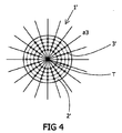
図4は、第2のねじりソノトロードによる他の接触面1’の上面図を示す。当該他の接触面1’は、円形である。停止面は、ここでは、参照符号2’が付されている。停止面2’から延びる突起部3’は、この場合、ねじり軸Tを中心として半径方向に延びる直線a3上に設けられる。 FIG. 4 shows a top view of another contact surface 1 'according to a second torsional sonotrode. The other contact surface 1 'is circular. The stop surface is here designated 2 '. The projection 3 'extending from the stop surface 2' is in this case provided on a straight line a3 extending radially around the torsion axis T.
上記突起部3および3’は、3つの側面を持つ角錐として形成することもでき、また、円錐型とすることもできる。
The
以下、図5を参照し、上記提案されたねじりソノトロードによる機能をさらに詳細に説明する。 Hereinafter, with reference to FIG. 5, the function by the above-mentioned proposed torsional sonotrode will be described in more detail.
図5において、ねじりソノトロードSの接触面1は、溶着すべき部品4上に接触して置かれる。当該部品は、プラスチック製または金属製とすることができ、特に、例えば、アルミニウム製とすることができる。参照符号5が付された他の部品は、上記部品4に溶着されるものである。当該他の部品もプラスチック製または金属製とすることができ、特に、アルミニウム製とすることができる。
In FIG. 5, the
図5に示すように、超音波溶着による接合部を生じるために必要な溶着圧力をかける際、停止面2が部品4上に接触して置かれた状態になるまで突起部3は部品4の内部に入り込む。突起部3が入り込む深さの最大値は、停止面2から突起部3の先端までの高さhにより定義される。この高さhは、接触面1の領域において部品4が有する厚さDよりも小さい。すなわち、接触面1の領域においては、突起部3は部品4の内部に入り込むに過ぎず、当該突起部3が部品4を通り抜けて、溶着接触領域6、すなわち、接触面1とは反対側の、部品4よりも遠位にある部品5との間に位置づけられる領域までは達することはない。
As shown in FIG. 5, when applying the welding pressure necessary to produce a joint by ultrasonic welding, the
島状に配置され、尖端形状を有する突起部3およびこれら突起部の間の平坦な停止面2により、溶着圧力をかけた際に、突起部3は、常に同じ深さまで部品4の内部に入り込むことになる。これにより、ねじりソノトロードSと部品4との間の再現性のある確実な接触が得られる。したがって、ねじりソノトロードSによって部品4に伝達される力のほぼ全てを確実に溶着接触領域6に伝えることができる。したがって、溶着接触領域6において、再現性のある強度が得られることとなる。
With the
1、1’ 接触面
2、2’ 停止面
3、3’ 突起部
4 部品
5 他の部品
6 溶着接触領域
a1、a2、a3 直線
D 厚さ
F 領域
G 底部
h 高さ
P 角錐面
S ねじりソノトロード
T ねじり軸
DESCRIPTION OF
有益な実施形態によれば、2つの隣接する突起部の間の距離は、0.4mm〜2.0mmの範囲であり、好ましくは、0.5mm〜1.0mmの範囲である。すなわち、上記突起部は、先行技術とは対照的に、V字型の切り込み底部を有する切り込みによってではなく、上記停止面の平坦面部分によって、互いに隔てられている。これにより、上記部品に対して上記突起部全体を確実に入り込ませることができる。 According to a beneficial embodiment, the distance between two adjacent protrusions is in the range of 0.4 mm to 2.0 mm, preferably in the range of 0.5 mm to 1.0 mm. That is, in contrast to the prior art, the projections are separated from one another not by cuts having a V-shaped cut bottom, but by the flat surface portion of the stop surface . Thus, the entire protrusion can be reliably inserted into the component.
全ての突起部の総底面積を、上記停止面の面積よりも小さいものとすることは有益である。「総底面積」との用語は、上記全ての突起部の底部の合計面積を意味する。突起部の底部の輪郭線は、当該突起部の側面と上記停止面の平坦面部分とが交わる部分の線により定義される。総底面積に対する停止面の面積の割合は、1.1〜8.0の範囲、好ましくは、2.0〜5.5の範囲とすることができる。上記接触面上における突起部の分布に関しては、特定の角度で交差する少なくとも2本の直線に沿って突起部を配置すれば有益となることが分かっている。上記直線が交差する特定の角度は、30°〜90°の範囲、好ましくは、60°または90°とすることができる。本発明の他の実施形態によれば、上記突起部は、ねじり軸を中心として半径方向に延びる直線に沿って配置することもできる。 It is advantageous to make the total base area of all the projections smaller than the area of the stop surface. The term "total base area" means the total area of the bottoms of all the above mentioned projections. The outline of the bottom of the projection is defined by the line of the intersection of the side of the projection and the flat surface of the stop surface . The ratio of the area of the stop surface to the total bottom area can be in the range of 1.1 to 8.0, preferably in the range of 2.0 to 5.5. With regard to the distribution of the protrusions on the contact surface, it has been found to be beneficial to arrange the protrusions along at least two straight lines intersecting at a particular angle. The particular angle at which the straight lines intersect may be in the range of 30 ° to 90 °, preferably 60 ° or 90 °. According to another embodiment of the present invention, the protrusions may be arranged along a straight line extending radially around the torsion axis.
本発明に係る上記方法によれば、溶着圧力をかけた際、上記突起部は、上記停止面の平坦面部分を基準として上記突起部の最大の高さにより定義された深さまでしか上記部品に入り込まない。この入り込む深さは、上記溶着すべき部品における上記接触面に接触する部分の厚さよりも小さい。したがって、上記突起部は、上記部品を通り抜けてしまうことはない。特に、上記突起部は、上記部品と他の部品との間の溶着接触領域部分にまで達することはない。 According to the above method of the present invention, when a welding pressure is applied, the projection only makes up the part to a depth defined by the maximum height of the projection with reference to the flat surface portion of the stop surface. I do not get in. The penetration depth is smaller than the thickness of the part in contact with the contact surface in the part to be welded. Therefore, the projection does not pass through the component. In particular, the projections do not reach the weld contact area between the part and the other part.
Claims (12)
前記接触面(1、1’)は、前記ねじり軸(T)に対して実質的に垂直方向に延在する平坦な停止面(2、2’)であって、尖端形状を有する突起部(3、3’)が島状に配置された停止面(2、2’)を備えることを特徴とする、ねじりソノトロード(S)。 A torsional sonotrode (S) comprising contact surfaces (1, 1 ') for transmitting to the part (4) to be welded torsional vibrations directed about the torsion axis (T),
The contact surface (1, 1 ′) is a flat stop surface (2, 2 ′) extending in a direction substantially perpendicular to the torsion axis (T), the projection having a pointed shape ( Torsion sonotrode (S), characterized in that 3, 3 ') comprise stop faces (2, 2') arranged in islands.
請求項1〜10のいずれかに記載のねじりソノトロード(S)を提供する工程と、
前記停止面(2)が前記溶着すべき部品(4)上に接触して置かれる状態になるまで、前記突起部(3、3’)を、前記部品(4)における前記接触面(1、1’)に接触する部分に対して圧入する工程であって、前記突起部(3、3’)の最大の高さ(h)は、前記部品(4)における前記接触面(1、1’)に接触する部分の厚さ(D)よりも小さい工程と、
ねじり超音波溶着により、前記部品(4)を、当該部品(4)に接触している他の部品(5)に溶着する工程とを含む、超音波溶着処理プロセス。 Ultrasonic welding process,
Providing a torsional sonotrode (S) according to any of the claims 1-10.
Until the stop surface (2) is placed in contact with the part (4) to be welded, the projection (3, 3 ') is the contact surface (1, 1) of the part (4) 1)) in the step of pressing into the part in contact with the part 1), the maximum height (h) of the protrusion (3, 3 ') being the contact surface (1, 1') of the part (4) A process smaller than the thickness (D) of the part in contact with
Welding the component (4) to another component (5) in contact with the component (4) by torsional ultrasonic welding.
Applications Claiming Priority (3)
| Application Number | Priority Date | Filing Date | Title |
|---|---|---|---|
| DE102010031258.4 | 2010-07-12 | ||
| DE102010031258A DE102010031258A1 (en) | 2010-07-12 | 2010-07-12 | Torsion sonotrode and ultrasonic welding process using a torsion sonotrode |
| PCT/EP2011/061363 WO2012007325A2 (en) | 2010-07-12 | 2011-07-06 | Torsion sonotrode and ultrasonic welding process using a torsion sonotrode |
Publications (2)
| Publication Number | Publication Date |
|---|---|
| JP2013538128A true JP2013538128A (en) | 2013-10-10 |
| JP2013538128A5 JP2013538128A5 (en) | 2014-04-17 |
Family
ID=44503761
Family Applications (1)
| Application Number | Title | Priority Date | Filing Date |
|---|---|---|---|
| JP2013519028A Pending JP2013538128A (en) | 2010-07-12 | 2011-07-06 | Ultrasonic welding process using torsion sonotrode and torsion sonotrode |
Country Status (7)
| Country | Link |
|---|---|
| US (1) | US8801882B2 (en) |
| EP (1) | EP2593291B1 (en) |
| JP (1) | JP2013538128A (en) |
| DE (1) | DE102010031258A1 (en) |
| ES (1) | ES2528101T3 (en) |
| PL (1) | PL2593291T3 (en) |
| WO (1) | WO2012007325A2 (en) |
Cited By (1)
| Publication number | Priority date | Publication date | Assignee | Title |
|---|---|---|---|---|
| US10744591B2 (en) | 2017-07-06 | 2020-08-18 | Nippon Mektron, Ltd. | Ultrasonic bonding jig, bonding structure, and bonding method |
Families Citing this family (10)
| Publication number | Priority date | Publication date | Assignee | Title |
|---|---|---|---|---|
| EP2446974B1 (en) | 2009-06-23 | 2023-08-16 | Toshiba Mitsubishi-Electric Industrial Systems Corporation | Ultrasonic bonding tool, method for manufacturing ultrasonic bonding tool, ultrasonic bonding method, and ultrasonic bonding apparatus |
| US9458629B2 (en) | 2012-09-28 | 2016-10-04 | Bemis Manufacturing Company | Method of forming raceway knockout |
| DE102012111734A1 (en) * | 2012-12-03 | 2014-06-05 | Schunk Sonosystems Gmbh | Ultrasonic welding device and method for welding electrical conductors |
| EP3078963B1 (en) * | 2015-04-07 | 2020-02-26 | Airbus Operations GmbH | System for non-destructive inspection of structural components |
| WO2017079085A1 (en) * | 2015-11-04 | 2017-05-11 | Orthodyne Electronics Corporation | Ribbon bonding tools, and methods of designing ribbon bonding tools |
| DE202017104190U1 (en) * | 2017-07-13 | 2018-10-16 | PP-Tech GmbH | Ultrasonic processing device and radial-resonant ultrasonic sonotrode |
| US10981245B2 (en) * | 2019-09-24 | 2021-04-20 | GM Global Technology Operations LLC | Apparatus for ultrasonic welding of polymers and polymeric composites |
| EP3835035A1 (en) * | 2019-12-11 | 2021-06-16 | Telsonic Holding AG | Method for joining workpieces and assembled article |
| US11772187B2 (en) * | 2021-04-30 | 2023-10-03 | Infineon Technologies Ag | Ultrasonic welding device |
| JP2023091901A (en) * | 2021-12-21 | 2023-07-03 | 三菱電機株式会社 | Semiconductor manufacturing equipment and method for manufacturing semiconductor device |
Citations (3)
| Publication number | Priority date | Publication date | Assignee | Title |
|---|---|---|---|---|
| JPH046384U (en) * | 1990-04-30 | 1992-01-21 | ||
| JP2006278849A (en) * | 2005-03-30 | 2006-10-12 | Nichicon Corp | Ultrasonic welding horn and manufacturing method of electrolytic capacitor using the same |
| JP4206496B2 (en) * | 2001-03-12 | 2009-01-14 | 四国化工機株式会社 | Container ultrasonic sealing method |
Family Cites Families (6)
| Publication number | Priority date | Publication date | Assignee | Title |
|---|---|---|---|---|
| DE3229076A1 (en) * | 1981-08-07 | 1983-03-24 | Pola Chemical Industries, Inc., Shizuoka | METHOD AND DEVICE FOR WELDING THE BOTTOM OF A TUBULAR RESIN CONTAINER |
| US4767492A (en) | 1986-04-18 | 1988-08-30 | Pola Chemical Industries, Inc. | Ultrasonic fuse-bonding sealing apparatus with improved contact surfaces |
| US4956213A (en) | 1988-02-17 | 1990-09-11 | Fuji Photo Film Co., Ltd. | Information recording medium |
| JP4792945B2 (en) * | 2005-01-28 | 2011-10-12 | 日産自動車株式会社 | Ultrasonic bonding apparatus and bonded structure |
| EP1930148A1 (en) * | 2006-12-07 | 2008-06-11 | Telsonic Holding AG | Use of a device for torsional, ultrasonic welding |
| EP2269807A1 (en) * | 2009-06-30 | 2011-01-05 | Telsonic Holding AG | Device, use of the device and method for torsional ultrasound welding |
-
2010
- 2010-07-12 DE DE102010031258A patent/DE102010031258A1/en active Pending
-
2011
- 2011-07-06 US US13/808,025 patent/US8801882B2/en active Active
- 2011-07-06 JP JP2013519028A patent/JP2013538128A/en active Pending
- 2011-07-06 ES ES11735830.9T patent/ES2528101T3/en active Active
- 2011-07-06 EP EP11735830.9A patent/EP2593291B1/en active Active
- 2011-07-06 PL PL11735830T patent/PL2593291T3/en unknown
- 2011-07-06 WO PCT/EP2011/061363 patent/WO2012007325A2/en active Application Filing
Patent Citations (3)
| Publication number | Priority date | Publication date | Assignee | Title |
|---|---|---|---|---|
| JPH046384U (en) * | 1990-04-30 | 1992-01-21 | ||
| JP4206496B2 (en) * | 2001-03-12 | 2009-01-14 | 四国化工機株式会社 | Container ultrasonic sealing method |
| JP2006278849A (en) * | 2005-03-30 | 2006-10-12 | Nichicon Corp | Ultrasonic welding horn and manufacturing method of electrolytic capacitor using the same |
Cited By (1)
| Publication number | Priority date | Publication date | Assignee | Title |
|---|---|---|---|---|
| US10744591B2 (en) | 2017-07-06 | 2020-08-18 | Nippon Mektron, Ltd. | Ultrasonic bonding jig, bonding structure, and bonding method |
Also Published As
| Publication number | Publication date |
|---|---|
| DE102010031258A1 (en) | 2012-01-12 |
| EP2593291B1 (en) | 2014-10-22 |
| US8801882B2 (en) | 2014-08-12 |
| WO2012007325A3 (en) | 2012-03-29 |
| PL2593291T3 (en) | 2015-05-29 |
| ES2528101T3 (en) | 2015-02-04 |
| US20130139955A1 (en) | 2013-06-06 |
| WO2012007325A2 (en) | 2012-01-19 |
| EP2593291A2 (en) | 2013-05-22 |
Similar Documents
| Publication | Publication Date | Title |
|---|---|---|
| JP2013538128A (en) | Ultrasonic welding process using torsion sonotrode and torsion sonotrode | |
| EP1685919B1 (en) | An apparatus and method for ultrasonically bonding two or more layers of material | |
| EP1568470A3 (en) | Laser welding of resin members using a ridge for enhancing weld strength | |
| CN112622281B (en) | Apparatus for ultrasonic welding of polymers and polymer composites | |
| ES2377646T3 (en) | Friction welding process | |
| WO2008030329A2 (en) | Ultrasonic welding using amplitude profiling | |
| US20060180635A1 (en) | Bonding tool and method | |
| JP6827386B2 (en) | Ultrasonic bonding jig, ultrasonic bonding method and bonding structure | |
| AU2016289742A1 (en) | Bonding objects together | |
| JP3864268B2 (en) | Horn for forming a welded part of a tube | |
| US11141925B2 (en) | Ultrasonic welding and welding horn having indenter | |
| JP4274885B2 (en) | Ultrasonic bonding apparatus and ultrasonic bonding method | |
| CN107685189B (en) | Vibration welding system and method | |
| WO2006041377A1 (en) | A method and an apparatus in ultrasonic sealing | |
| US20230001648A1 (en) | Method for connecting workpieces, and assembled object | |
| US9449595B2 (en) | Sonotrode with processing channel | |
| US11517973B2 (en) | Welding element and welding method for connecting a weld element to a workpiece | |
| JP6975917B2 (en) | Joint structure | |
| JP2022016741A (en) | Ultrasonic bonding device, tip member of ultrasonic bonding device, and fitting method for tip member | |
| JPH08150669A (en) | Net for ultrasonic welding and ultrasonic welding method | |
| CN217701798U (en) | Ultrasonic welding tooth structure, welding head and ultrasonic welding device for lithium ion battery | |
| WO2023136302A1 (en) | Puncture needle | |
| KR20230031092A (en) | Method and apparatus for joining different materials | |
| CN206663815U (en) | Using the plastics welding structure of ultrasonic technology | |
| KR20120084669A (en) | Ultrasonic bonding apparatus |
Legal Events
| Date | Code | Title | Description |
|---|---|---|---|
| A521 | Request for written amendment filed |
Free format text: JAPANESE INTERMEDIATE CODE: A523 Effective date: 20140225 |
|
| A621 | Written request for application examination |
Free format text: JAPANESE INTERMEDIATE CODE: A621 Effective date: 20140225 |
|
| A977 | Report on retrieval |
Free format text: JAPANESE INTERMEDIATE CODE: A971007 Effective date: 20141211 |
|
| A131 | Notification of reasons for refusal |
Free format text: JAPANESE INTERMEDIATE CODE: A131 Effective date: 20150203 |
|
| A521 | Request for written amendment filed |
Free format text: JAPANESE INTERMEDIATE CODE: A523 Effective date: 20150501 |
|
| A02 | Decision of refusal |
Free format text: JAPANESE INTERMEDIATE CODE: A02 Effective date: 20150825 |