JP2013536493A - Touchless sensing and gesture recognition using continuous wave ultrasound signals - Google Patents
Touchless sensing and gesture recognition using continuous wave ultrasound signals Download PDFInfo
- Publication number
- JP2013536493A JP2013536493A JP2013518670A JP2013518670A JP2013536493A JP 2013536493 A JP2013536493 A JP 2013536493A JP 2013518670 A JP2013518670 A JP 2013518670A JP 2013518670 A JP2013518670 A JP 2013518670A JP 2013536493 A JP2013536493 A JP 2013536493A
- Authority
- JP
- Japan
- Prior art keywords
- impulse response
- channel impulse
- processor
- sound
- computer
- Prior art date
- Legal status (The legal status is an assumption and is not a legal conclusion. Google has not performed a legal analysis and makes no representation as to the accuracy of the status listed.)
- Pending
Links
Images


Classifications
-
- G—PHYSICS
- G06—COMPUTING; CALCULATING OR COUNTING
- G06F—ELECTRIC DIGITAL DATA PROCESSING
- G06F3/00—Input arrangements for transferring data to be processed into a form capable of being handled by the computer; Output arrangements for transferring data from processing unit to output unit, e.g. interface arrangements
- G06F3/01—Input arrangements or combined input and output arrangements for interaction between user and computer
- G06F3/011—Arrangements for interaction with the human body, e.g. for user immersion in virtual reality
-
- G—PHYSICS
- G01—MEASURING; TESTING
- G01S—RADIO DIRECTION-FINDING; RADIO NAVIGATION; DETERMINING DISTANCE OR VELOCITY BY USE OF RADIO WAVES; LOCATING OR PRESENCE-DETECTING BY USE OF THE REFLECTION OR RERADIATION OF RADIO WAVES; ANALOGOUS ARRANGEMENTS USING OTHER WAVES
- G01S15/00—Systems using the reflection or reradiation of acoustic waves, e.g. sonar systems
- G01S15/02—Systems using the reflection or reradiation of acoustic waves, e.g. sonar systems using reflection of acoustic waves
- G01S15/06—Systems determining the position data of a target
- G01S15/08—Systems for measuring distance only
- G01S15/32—Systems for measuring distance only using transmission of continuous waves, whether amplitude-, frequency-, or phase-modulated, or unmodulated
- G01S15/325—Systems for measuring distance only using transmission of continuous waves, whether amplitude-, frequency-, or phase-modulated, or unmodulated using transmission of coded signals, e.g. of phase-shift keyed [PSK] signals
-
- G—PHYSICS
- G01—MEASURING; TESTING
- G01S—RADIO DIRECTION-FINDING; RADIO NAVIGATION; DETERMINING DISTANCE OR VELOCITY BY USE OF RADIO WAVES; LOCATING OR PRESENCE-DETECTING BY USE OF THE REFLECTION OR RERADIATION OF RADIO WAVES; ANALOGOUS ARRANGEMENTS USING OTHER WAVES
- G01S15/00—Systems using the reflection or reradiation of acoustic waves, e.g. sonar systems
- G01S15/02—Systems using the reflection or reradiation of acoustic waves, e.g. sonar systems using reflection of acoustic waves
- G01S15/50—Systems of measurement, based on relative movement of the target
-
- G—PHYSICS
- G01—MEASURING; TESTING
- G01S—RADIO DIRECTION-FINDING; RADIO NAVIGATION; DETERMINING DISTANCE OR VELOCITY BY USE OF RADIO WAVES; LOCATING OR PRESENCE-DETECTING BY USE OF THE REFLECTION OR RERADIATION OF RADIO WAVES; ANALOGOUS ARRANGEMENTS USING OTHER WAVES
- G01S15/00—Systems using the reflection or reradiation of acoustic waves, e.g. sonar systems
- G01S15/87—Combinations of sonar systems
- G01S15/876—Combination of several spaced transmitters or receivers of known location for determining the position of a transponder or a reflector
-
- G—PHYSICS
- G01—MEASURING; TESTING
- G01S—RADIO DIRECTION-FINDING; RADIO NAVIGATION; DETERMINING DISTANCE OR VELOCITY BY USE OF RADIO WAVES; LOCATING OR PRESENCE-DETECTING BY USE OF THE REFLECTION OR RERADIATION OF RADIO WAVES; ANALOGOUS ARRANGEMENTS USING OTHER WAVES
- G01S7/00—Details of systems according to groups G01S13/00, G01S15/00, G01S17/00
- G01S7/52—Details of systems according to groups G01S13/00, G01S15/00, G01S17/00 of systems according to group G01S15/00
- G01S7/523—Details of pulse systems
- G01S7/526—Receivers
- G01S7/527—Extracting wanted echo signals
- G01S7/5273—Extracting wanted echo signals using digital techniques
-
- G—PHYSICS
- G06—COMPUTING; CALCULATING OR COUNTING
- G06F—ELECTRIC DIGITAL DATA PROCESSING
- G06F3/00—Input arrangements for transferring data to be processed into a form capable of being handled by the computer; Output arrangements for transferring data from processing unit to output unit, e.g. interface arrangements
- G06F3/01—Input arrangements or combined input and output arrangements for interaction between user and computer
- G06F3/017—Gesture based interaction, e.g. based on a set of recognized hand gestures
Abstract
本実施形態は、持続波音信号を使用したタッチレス感知およびジェスチャー認識のためのシステムおよび方法を提供する。送信機によって放出された、超音波などの持続波音は、物体から反射し、1つまたは複数の受音器によって受信され得る。音信号は時間的に符号化され得る。受信された音信号は、チャネルインパルス応答を判断するかまたは飛行時間を計算するために、処理され得る。判断されたチャネルインパルス応答は、認識可能な特徴または角度を抽出するために処理され得る。抽出された特徴は、一致した特徴に関連するユーザ入力ジェスチャーを識別するために、特徴のデータベースと比較され得る。チャネルインパルス応答曲線の角度が入力ジェスチャーに関連付けられ得る。各受音器からの飛行時間値は、反射物体の座標を判断するために使用され得る。実施形態は、グラフィカルユーザインターフェースの一部として実行され得る。実施形態は、放出器のロケーションを判断するために使用され得る。 The present embodiment provides a system and method for touchless sensing and gesture recognition using continuous wave sound signals. Continuous wave sound, such as ultrasound, emitted by a transmitter may be reflected from an object and received by one or more receivers. The sound signal can be encoded in time. The received sound signal can be processed to determine the channel impulse response or to calculate the time of flight. The determined channel impulse response can be processed to extract recognizable features or angles. The extracted features may be compared to a feature database to identify user input gestures associated with the matched features. The angle of the channel impulse response curve can be associated with the input gesture. The time of flight value from each receiver can be used to determine the coordinates of the reflective object. Embodiments can be implemented as part of a graphical user interface. Embodiments can be used to determine the location of the emitter.
Description
[関連出願]
本出願は、その内容全体が参照により組み込まれる、2010年6月29日に出願された「Touchless Sensing and Gesture Recognition using Continuous Wave Sound Signals」と題する米国仮特許出願第61/359,728号の優先権の利益を主張する。
[Related applications]
This application is a priority of US Provisional Patent Application No. 61 / 359,728, filed June 29, 2010, entitled “Touchless Sensing and Gesture Recognition using Continuous Wave Sound Signals,” which is incorporated by reference in its entirety. Insist on the interests of rights.
[分野]
本発明は、一般に、コンピューティングデバイスのためのユーザインターフェースシステムに関し、より詳細には、持続波音(continuous-wave sound)を採用するタッチレスユーザインターフェースに関する。
[Field]
The present invention relates generally to user interface systems for computing devices, and more particularly to touchless user interfaces that employ continuous-wave sound.
[背景]
超音波は、人間の聴覚の上限を上回るまたは約20kHzを上回る周波数において動作するものとして定義される周期的音圧である。超音波は、画像化、ソースロケーション判断および範囲測定のための広範囲の適用例において実行されている。これらの適用例の多くは、媒体を通り、反射を介して媒体内の物体の構造情報を与える、超音波の能力に焦点を当てている。たいていの適用例は、超音波が放出されるときとエコーが検出されるときとの間の時間遅延を測定することによって、超音波を利用する。大まかに言えば、超音波システムの2つのタイプはパルスエコーと持続波である。
[background]
Ultrasound is a periodic sound pressure defined as operating at a frequency above the upper limit of human hearing or above about 20 kHz. Ultrasound has been implemented in a wide range of applications for imaging, source location determination and range measurement. Many of these applications focus on the ability of ultrasound to pass through the medium and provide structural information of objects in the medium via reflections. Most applications utilize ultrasound by measuring the time delay between when the ultrasound is emitted and when an echo is detected. Broadly speaking, two types of ultrasound systems are pulse echoes and continuous waves.
実施形態は、持続波超音波信号を使用した、ユーザインターフェースとして使用するのに好適なタッチレス感知およびジェスチャー(gesture)認識のためのシステムおよび方法を提供する。超音波信号が、送信され、ユーザの指または手などの物体から反射し得る。反射した超音波信号は超音波マイクロフォンによって受信され得る。受信された超音波信号に基づいてチャネルインパルス応答(channel impulse response)が計算され得る。チャネルインパルス応答は異なるフィルタにかけられ得、認識可能な特徴が抽出または認識され得る。これらの認識可能な特徴は、抽出された特徴がいずれかの既知のパターンに一致するかどうかを判断するために、あらかじめ定義されたユーザジェスチャーに相関された特徴の記憶されたパターンと比較され得る。抽出された特徴が既知のパターンに一致する場合、一致するパターンに関連するコマンド(たとえば、ユーザ入力コマンド)がコンピューティングデバイスによって実行され得る。さらなる実施形態では、チャネル応答における認識可能な特徴が特定の反射信号に相関され得る。楕円交点(elliptic intersect)計算を使用することなどによって、コンピューティングデバイスに対する反射物体の座標を導出するために、反射信号の飛行時間が計算され、使用され得る。また、この方法は、反射物体の動きを一連の位置として追跡し得、動き追跡データは、認識を行うためにジェスチャーに相関され得る。 Embodiments provide systems and methods for touchless sensing and gesture recognition suitable for use as a user interface using continuous wave ultrasound signals. An ultrasound signal may be transmitted and reflected from an object such as a user's finger or hand. The reflected ultrasound signal can be received by an ultrasound microphone. A channel impulse response may be calculated based on the received ultrasound signal. The channel impulse response can be filtered differently and recognizable features can be extracted or recognized. These recognizable features can be compared to a stored pattern of features correlated with predefined user gestures to determine whether the extracted features match any known pattern. . If the extracted features match a known pattern, commands (eg, user input commands) associated with the matching pattern may be executed by the computing device. In further embodiments, recognizable features in the channel response can be correlated to a particular reflected signal. The time of flight of the reflected signal can be calculated and used to derive the coordinates of the reflecting object relative to the computing device, such as by using an elliptic intersect calculation. The method can also track the motion of the reflective object as a series of positions, and the motion tracking data can be correlated to gestures for recognition.
本明細書に組み込まれ、本明細書の一部をなす添付の図面は、本発明の例示的な実施形態を示し、上記の概略的な説明および下記の発明を実施するための形態とともに、本発明の特徴を説明するのに役立つ。 The accompanying drawings, which are incorporated in and constitute a part of this specification, illustrate exemplary embodiments of the invention, and together with the general description above and the detailed description below, illustrate the present invention. It serves to explain the features of the invention.
[詳細な説明]
様々な実施形態について添付の図面を参照しながら詳細に説明する。可能な場合はいつでも、同じまたは同様の部分を指すために図面全体にわたって同じ参照番号を使用する。特定の例および実行形態になされる言及は、説明のためであり、本発明の範囲または特許請求の範囲を限定するものではない。
[Detailed description]
Various embodiments will be described in detail with reference to the accompanying drawings. Wherever possible, the same reference numbers will be used throughout the drawings to refer to the same or like parts. References made to particular examples and implementations are for illustrative purposes, and are not intended to limit the scope of the invention or the claims.
「例示的」という単語は、本明細書では、「例、事例、または例示の働きをすること」を意味するために使用する。「例示的」として本明細書で説明するいかなる実行形態も、必ずしも他の実行形態よりも好ましいまたは有利であると解釈されるべきではない。 The word “exemplary” is used herein to mean “serving as an example, instance, or illustration”. Any implementation described herein as "exemplary" is not necessarily to be construed as preferred or advantageous over other implementations.
本明細書で使用する「コンピューティングデバイス」という用語は、限定はしないが、ラップトップおよびデスクトップコンピュータ、テレビジョン、家庭用電気器具、セルラー電話、パーソナルテレビジョンデバイス、携帯情報端末(PDA)、パームトップコンピュータ、ワイヤレス電子メール受信機(たとえば、Blackberry(登録商標)およびTreo(登録商標)デバイス)、マルチメディアインターネット対応セルラー電話(たとえば、Blackberry Storm(登録商標))、全地球測位システム(GPS)受信機、ワイヤレスゲームコントローラ、車両(たとえば、自動車)内の受信機、対話型ゲームデバイス、ノートブック、スマートブック、ネットブック、モバイルテレビジョンデバイス、または任意のデータ処理装置を含む、ユーザインターフェースをもつ任意の形態のプログラマブルコンピュータデバイスを指す。 As used herein, the term “computing device” includes, but is not limited to, laptops and desktop computers, televisions, consumer electronics, cellular phones, personal television devices, personal digital assistants (PDAs), palms Top computers, wireless e-mail receivers (eg Blackberry® and Treo® devices), multimedia internet-enabled cellular phones (eg Blackberry Storm®), Global Positioning System (GPS) reception Machine, wireless game controller, receiver in vehicle (eg car), interactive game device, notebook, smart book, netbook, mobile television device, or Including the data processing device refers to a programmable computer device in any form with a user interface.
様々な実施形態は、デバイスから放出され、1つまたは複数の検出器またはマイクロフォンによって受信された持続波超音波信号を使用した、コンピューティングデバイスによるタッチレスユーザインターフェース感知およびジェスチャー認識のためのシステムおよび方法を提供する。持続波超音波は、送信機またはスピーカーによって放出され、物体(たとえば、ユーザの手)から反射され、1つまたは複数の受信機またはマイクロフォンによって受信され得る。たとえば、超音波放出器またはスピーカーが、適宜に符号化された持続波超音波を送信し得る。その超音波は、空中を伝搬し、ユーザの手が反射検出ゾーン内に位置する場合、その手から反射し得る。反射した超音波は、コンピューティングデバイスの周りに位置する1つ、2つ、3つ、またはそれ以上の超音波検出器またはマイクロフォンによって受信され得る。様々な実施形態では、「チャネル」は、超音波放出器から空中を通ってユーザの手に至る音経路、ユーザの手から空中を通って各検出器に至る反射、および各検出器の応答を含み得る。そのようなチャネルの特性は、既知の信号処理方法および回路(たとえば、デジタル信号プロセッサ)を使用して判断され得るチャネルインパルス応答で表され得る。したがって、ユーザがコンピューティングデバイスの反射検出ゾーン内で手または物体を移動するにつれて、チャネルの特性およびチャネルインパルス応答は、反射超音波の異なる送信経路により変化することになる。これは、放出された超音波に対する手表面の入射角の変化による反射エコーのパターンの変化を含み得る。経時的なチャネルインパルス応答のそのような変化は、対象とするユーザ入力ジェスチャーを認識するためにメモリに記憶された既知のパターンと比較され得るパターンを明らかにするために、分析され得る。また、認識されたチャネルインパルス応答パターンを生成するユーザの手のいずれかの大きい反射または部分が処理されて、超音波の飛行時間が測定され得、その飛行時間から、コンピューティングデバイスは、よく知られている楕円三角測量計算を使用してコンピューティングデバイスを囲む3D空間内の反射表面のロケーションを判断することができる。反射表面までの距離を判断するための正確な方法は、システムにおける雑音を考慮するために、カルマンフィルタ処理(Kalman filtering)などのよく知られている処理アルゴリズムを使用し得る。 Various embodiments provide a system for touchless user interface sensing and gesture recognition by a computing device using continuous wave ultrasound signals emitted from the device and received by one or more detectors or microphones Provide a method. Continuous wave ultrasound can be emitted by a transmitter or speaker, reflected from an object (eg, a user's hand), and received by one or more receivers or microphones. For example, an ultrasound emitter or speaker may transmit appropriately encoded continuous wave ultrasound. The ultrasound wave propagates through the air and can be reflected from the hand if the user's hand is located within the reflection detection zone. The reflected ultrasound can be received by one, two, three, or more ultrasound detectors or microphones located around the computing device. In various embodiments, the “channel” is the acoustic path from the ultrasound emitter through the air to the user's hand, the reflection from the user's hand through the air to each detector, and the response of each detector. May be included. The characteristics of such a channel can be represented by a channel impulse response that can be determined using known signal processing methods and circuitry (eg, a digital signal processor). Thus, as the user moves a hand or object within the reflection detection zone of the computing device, the channel characteristics and channel impulse response will change due to different transmission paths of the reflected ultrasound. This may include a change in the pattern of the reflected echo due to a change in the incident angle of the hand surface with respect to the emitted ultrasound. Such changes in channel impulse response over time can be analyzed to reveal a pattern that can be compared to a known pattern stored in memory to recognize a user input gesture of interest. Also, any large reflections or portions of the user's hand that generate a recognized channel impulse response pattern can be processed to measure the time of flight of the ultrasound, from which the computing device knows well. The ellipsoidal triangulation calculations that are performed can be used to determine the location of the reflective surface in 3D space surrounding the computing device. An accurate method for determining the distance to the reflective surface may use well-known processing algorithms such as Kalman filtering to account for noise in the system.
3次元ユーザ入力ジェスチャー認識能力を与えることに加えて、様々な実施形態のタッチレスジェスチャー感知能力は他の利点を与える。システムは、コンピューティングデバイスの周りの30〜40センチメートル内など、コンピューティングデバイスを囲む大きい体積内のユーザジェスチャーを検出し、解釈することができる。さらに、ユーザインターフェース空間がコンピューティングデバイスの上方にあるので、ユーザインターフェースは、外部の状態、たとえば、湿気、ほこりなどに対して耐性があるように構成され得る。したがって、様々な実施形態は、従来のコンピュータが不適当である状況とシステムとロケーションとにおける適用例を有し得る。 In addition to providing 3D user input gesture recognition capabilities, the touchless gesture detection capabilities of various embodiments provide other advantages. The system can detect and interpret user gestures within a large volume surrounding the computing device, such as within 30-40 centimeters around the computing device. Further, since the user interface space is above the computing device, the user interface can be configured to be resistant to external conditions such as moisture, dust, and the like. Thus, various embodiments may have applications in situations, systems and locations where conventional computers are inappropriate.
概して、持続波超音波信号は、受信される反射信号が放出される信号と相関されることを可能にする方法で変調され得る。信号を照合することにより、システムは、チャネルインパルス応答を判断すること、あるいは送信と受信との間の時間差、または飛行時間を計算することが可能になり得る。システムチャネル入力応答の変化が、認識され、トレーニングセッションから記憶されたパターンと比較されることを可能にするために、システムチャネル入力応答スナップショットまたは画像が経時的にバッファされ得る。チャネルインパルス応答のそのようなバッファされた画像は、ユーザ入力ジェスチャーの事前トレーニングされたテンプレートライブラリ(template library)に一致し得る特徴を抽出するための特殊フィルタ処理を使用してフィルタ処理され得る。インパルス応答を処理することに加えて、最も強いエコーまたは最初の到着エコーに関連付けられ得るような特定のエコー特徴が、飛行時間分析を使用して3D空間におけるエコーソースのロケーションの正確な推定値を取得するために処理され得る。雑音の存在下で飛行時間または距離を正確に判断するためにカルマンフィルタ処理などの数学的処理が使用され得、これは、たいていの使用状況における実情である可能性がある。受信した反射を分析し、照合するために、実施形態は、様々な信号処理要素を備え得る。これらの信号処理要素は、受信したチャネル応答からパターンおよび特徴を除外し得、チャネルにおける反射物体を決して解像することなしにこれらの特徴をジェスチャーに相関させ得る。 In general, the continuous wave ultrasound signal can be modulated in a manner that allows the received reflected signal to be correlated with the emitted signal. By collating the signal, the system may be able to determine the channel impulse response or calculate the time difference between transmission and reception, or the time of flight. System channel input response snapshots or images may be buffered over time to allow changes in the system channel input response to be recognized and compared to patterns stored from a training session. Such a buffered image of the channel impulse response can be filtered using special filtering to extract features that can match a pretrained template library of user input gestures. In addition to processing the impulse response, certain echo features, such as those that can be associated with the strongest echo or first arrival echo, use time-of-flight analysis to provide an accurate estimate of the location of the echo source in 3D space. Can be processed to obtain. Mathematical processing such as Kalman filtering can be used to accurately determine time of flight or distance in the presence of noise, which can be the case in most usage situations. Embodiments can include various signal processing elements to analyze and collate received reflections. These signal processing elements can exclude patterns and features from the received channel response and can correlate these features to gestures without ever resolving reflective objects in the channel.
チャネルインパルス応答における検出されたパターンを、ユーザトレーニングセッションなどからの、メモリに記憶されたパターンと比較することによって、コンピューティングデバイスは、最も厳密に一致するパターンを識別することができる。特定のユーザ入力コマンドを特定のトレーニングされたジェスチャーパターンに相関させることによって、コンピューティングデバイスは、特定のユーザ手移動をユーザ入力コマンドとして認識するように構成され得る。したがって、いくつかの実施形態では、超音波検出システムは、オペレーティングシステムのグラフィカルユーザインターフェース部分の一部として実行され得る。そのような実施形態では、チャネルインパルス応答パターンがメモリ中のパターンに一致したとき、関連するユーザコマンドがコンピューティングデバイスによって識別され、実行され得る。このようにして、ユーザは、既知のポインティングデバイスまたはタッチスクリーンディスプレイを使用してユーザコマンドが入力され得る方法と同様に、コンピューティングデバイスの上方でまたはそれの近傍内で手を向けるかまたは移動することによって、コンピューティングデバイスを制御し得る。 By comparing the detected pattern in the channel impulse response with a pattern stored in memory, such as from a user training session, the computing device can identify the most closely matched pattern. By correlating specific user input commands to specific trained gesture patterns, the computing device may be configured to recognize specific user hand movements as user input commands. Thus, in some embodiments, the ultrasound detection system can be implemented as part of the graphical user interface portion of the operating system. In such embodiments, when the channel impulse response pattern matches the pattern in memory, the associated user command can be identified and executed by the computing device. In this way, the user points or moves his hand over or within the computing device, similar to the manner in which user commands can be entered using known pointing devices or touch screen displays. Thereby controlling the computing device.
様々な実施形態について超音波を送信および受信することとして説明するが、それらの実施形態は、典型的な超音波領域を下回る周波数をもつ音を用いて同じく実行され得る。放出された周波数が可聴範囲を上回るとすれば、様々な実施形態は、本明細書で説明する方法で高周波音を用いて実行され得る。超音波は、ユーザの手の微細構造の解像度を可能にする超音波の小さい波長により、有利である。ただし、空気の低い密度のために、より低い周波数の音は、従来のスピーカーを使用して生成するのがより容易かつ効率的であり得、従来のマイクロフォンにおいて受信するのがより容易であり得る。したがって、本明細書では、超音波への言及は、明確に具陳されている場合を除いて、特許請求の範囲を特定の周波数レンジ内の音に限定するものではない。 Although various embodiments are described as transmitting and receiving ultrasound, the embodiments can also be performed using sound with frequencies below the typical ultrasound region. Given that the emitted frequency is above the audible range, various embodiments may be performed using high frequency sound in the manner described herein. Ultrasound is advantageous due to the small wavelength of the ultrasound that allows the resolution of the microstructure of the user's hand. However, due to the low density of air, lower frequency sounds can be easier and more efficient to generate using conventional speakers and can be easier to receive on conventional microphones. . Accordingly, in this specification, reference to ultrasound does not limit the scope of the claims to those within a particular frequency range, unless explicitly stated.
図1に、ラップトップコンピュータ100上の様々な実施形態の例示的な実行形態を示す。図示の実施形態では、ラップトップコンピュータ100内のユーザインターフェースシステムが、超音波放出器(ultrasound emmitter)101と、コンピュータ100の様々な部分上に位置する複数の超音波検出器102a、102b、102cとを含む。使用中に、ユーザは、コンピュータ100の上方のまたはそれの近傍内の3D空間106内に手104を配置し得る。タッチパッド110などの従来のポインティングデバイスを使用するのではなく、ユーザは、コンピューティングデバイスが認識および実行することができるユーザ入力ジェスチャーを実行するために、超音波検出器102a、102b、102cによって超音波反射が検出され得るゾーン(本明細書では反射検出ゾーンと呼ぶ)内で手104を移動し得る。ジェスチャーのグラフィカル表現が、他のグラフィカルユーザインターフェースシステムと同様に、ディスプレイ108上に提示され得る。したがって、コンピュータ100の上方のまたはそれの周りの座標系106のX軸、Y軸およびZ軸内で手104を移動することによって、ユーザは、どの表面にもタッチすることなしにコンピュータ100とインターフェースすることができる。実施形態は、ユーザ入力ジェスチャーが3D空間において実行され得るタッチレスユーザインターフェースシステムを可能にし、厳密に2次元である従来のグラフィカルユーザインターフェースデバイス(たとえば、コンピュータマウス、タッチパッドまたはタッチスクリーン)とは異なる、完全な3Dユーザインターフェース能力を可能にする。
FIG. 1 illustrates an exemplary implementation of various embodiments on a
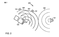
図2に、ユーザの手104の位置および配向を検出するために超音波がどのように使用され得るかについての単純な表現を示す。超音波放出器101が、空中を伝搬する持続波超音波206を放出し得る。放出される超音波において情報を符号化することによって、持続波音を用いてユーザの手104に関する位置情報が判断され得る。表現の簡単のために、持続波超音波内の認識可能な特徴が同心円弧で示されている。放出された超音波206は、ユーザの手104が反射検出ゾーン内にあるとき、ユーザの手104から反射することになり、それにより、反射超音波207、208が生じる。ユーザの手は3次元であるので、ユーザの手の様々な特徴からの反射から複数の反射超音波波面207、208が生じることになる。それらの特徴は超音波放出器101から異なる距離に位置するので、所与の瞬間において各特徴から反射される波面は異なることになる。さらに、ユーザの手の様々な特徴から各超音波検出器102までの距離も異なることになる。したがって、ユーザの手104から反射される音は、各々が互いにわずかに時間的にオフセットされた複数の波面において、検出器102に到着することになる。このようにして、検出器102に到着する反射超音波は、ユーザの手のロケーション、形状および配向に関する情報を符号化する。従来の画像化超音波システムでは、反射表面の画像を生成するために、検出器102によって測定されたエコー到着時間が使用され得る。
FIG. 2 shows a simple representation of how ultrasound can be used to detect the position and orientation of the user's
現代の超音波画像化システムは、正確な画像を現像するためにフェーズドアレイシステムを使用する。しかしながら、そのような画像生成は、プロセッサ集約的であり、したがって、基本ユーザインターフェースシステムには好適でない。様々な実施形態は、画像化プロセスをバイパスし、代わりに、放出器101、反射表面104、および検出器102、ならびに介在する空間にわたる、通信チャネルのチャネルインパルス応答の変化を処理することによって、受信された超音波において符号化されたロケーション、形状および配向情報を利用する。
Modern ultrasound imaging systems use a phased array system to develop accurate images. However, such image generation is processor intensive and is therefore not suitable for basic user interface systems. The various embodiments bypass the imaging process and instead receive by processing changes in the channel impulse response of the communication channel across the
図3に、様々な実施形態を実行するコンピューティングシステム300を示す。実施コンピューティングシステム300は、超音波放出器101と、コンピューティングデバイスの中央プロセッサ304に結合されたデジタル信号プロセッサ302に結合された1つまたは複数の超音波検出器またはマイクロフォン102a、102b、102cとを含み得る。中央プロセッサ304は、メモリ306に結合され得、また、超音波放出器101に結合された超音波変調器/増幅器回路308に結合され得る。超音波変調器/増幅器回路308は、擬似乱数または擬似ランダム雑音(pseudorandom noise)など、持続波超音波中に符号化されるべき情報をプロセッサ304から受信するように構成され得る。超音波変調器/増幅器回路308は、変調された超音波を放出するために超音波放出器101に適用される電気信号を生成するために、この情報を使用し得る。いくつかの実行形態では、超音波変調器/増幅器回路308は、デジタル信号プロセッサ302に結合され得、超音波に変調されるべき情報の信号を中央プロセッサ304からではなくデジタル信号プロセッサ302から受信するように構成され得る。
FIG. 3 illustrates a
いくつかの実施形態では、超音波放出器101は、コンピューティングデバイスの表面上に取り付けられた超音波トランスデューサなどの別個の音放出構成要素であり得る。他の実施形態では、超音波放出器101は、圧電スピーカーまたはツイータ要素など、コンピューティングデバイスのスピーカーまたはそのスピーカー内の要素であり得る。同様に、いくつかの実施形態では、超音波検出器またはマイクロフォン102a、102b、102cは、専用超音波トランスデューサなどの別個の構成要素であり得る。他の実施形態では、超音波は、高周波感知構成要素など、コンピューティングデバイスのマイクロフォンまたはそのマイクロフォン内の要素によって感知され得る。さらなる実施形態では、1つまたは複数の超音波トランスデューサが、超音波放出器または超音波検出器のいずれかとして機能し得る。
In some embodiments, the
上記で説明したように、様々な実施形態は、超音波放出器101と、空中を通って超音波放出器101からユーザの手104に至る伝搬経路312と、ユーザの指または手104からの反射と、空中を通ってユーザの手104から超音波検出器102aに至る伝搬経路314と、超音波検出器102a、102b、102cとを包含するように定義された、通信チャネル310を利用する。したがって、コンピューティングシステム300中に含まれる超音波放出器101と超音波検出器102a、102b、102cの各々との間に別個の通信チャネルが存在することになる。様々な実施形態は単一の超音波検出器102aを用いて実行され得るが、ユーザの手104のロケーション、形状、および配向に関するより多くの情報を取得するために、またはユーザ入力ジェスチャーをより良く区別するために、2つ以上の超音波検出器がコンピューティングシステム300上の様々なロケーションに位置し得る。
As described above, various embodiments include an
すべての通信チャネルのように、空中を通る超音波緩和チャネル310の要素のうちのいずれか1つの変化により、チャネルインパルス応答が変化し得る。たいていの動作条件において、超音波放出器101および検出器102aの性質、ならびに周囲空気の音伝搬特性が、典型的なユーザインターフェースジェスチャーの時間フレーム内で一定であると推定され得、これはわずか数秒にわたるものである。したがって、温度、湿度などの変化による通信チャネル312のこれらの要素の変化は無視され得る。したがって、通信チャネル310の分析は、インパルス応答のすべての変化が、ユーザの手104などの反射表面のロケーション、形状、および配向の変化によるものであると推定して、達成され得る。たとえば、超音波放出器101に向かうユーザの手104の移動により、放出器から手までの伝搬経路312が減少し、たいがい、手から検出器までの伝搬経路314が変化(延長または短縮)することになる。また、指を回転させること、伸ばすことまたは引っ込めることなど、ユーザの手104の移動により、入射する超音波に対して反射表面の配向が変化し、したがって、検出器102aによって受信される反射超音波のパターンが変化することになる。さらに、超音波放出器101に向かうまたはそれから離れるユーザの手104の急速な移動により、超音波検出器102aによって受信される反射超音波のドップラーシフトも生じ得る。反射検出ゾーン内のユーザの手104の移動から生じる通信チャネル310のそのような変化は、チャネルのインパルス応答に反映されることになる。したがって、経時的な通信チャネル310のインパルス応答の変化を分析することによって、コンピューティングシステム300は、ユーザの手104の位置、形状および配向に関する情報を取得することができる。以下で説明する図20に示すように3次元で離間したように、コンピューティングシステム300上の様々なロケーションに3つ以上の超音波検出器102a、102b、102cを配置することによって、コンピューティングシステム300は、ユーザの手104に関する3次元位置情報を取得することができる。
As with all communication channels, a change in any one of the elements of the
超音波検出器102a、102b、102cによって受信された超音波信号のサンプリングに関与する計算、および各通信チャネル310についてのチャネルインパルス応答の判断が、デジタル信号プロセッサ302または別の適切に構成された処理回路によって実行され得る。以下で説明する様々な実施形態のフィルタ処理、グレースケール(grey scale)処理、および統計分析など、チャネルインパルス応答データの処理が、デジタル信号プロセッサ302において実行されるか、または部分的にデジタル信号プロセッサ302において実行され、また、部分的に中央プロセッサ304において実行され得る。デジタル信号プロセッサ302および/または中央プロセッサ304において実行された処理によってチャネルインパルス応答から抽出された認識可能な特徴が、中央プロセッサ304またはコンピューティングシステム300内の別のプロセッサによって実行されるパターン比較アルゴリズムを使用して、メモリ306に記憶されたパターンと比較され得る。中央プロセッサ304が、通信チャネル310のうちの1つまたは複数のチャネルインパルス応答から抽出されたパターンが、メモリ306に記憶されたパターンに一致すると判断した場合、中央プロセッサ304は、一致したパターンに関連するユーザ入力コマンドを判断し、他のユーザ入力コマンドのようにそのコマンドを実行し得る。
The calculations involved in sampling the ultrasound signals received by the
図4に、実施システム400の機能モジュールおよびハードウェア要素を示す。放出される持続波超音波を生成するために、擬似ランダム雑音または擬似乱数生成器モジュール402が擬似ランダムコードを生成し得る。このコードはスペクトル拡散変調器およびパルス圧縮モジュール404に与えられ得、スペクトル拡散変調器およびパルス圧縮モジュール404は擬似ランダム雑音をデジタル情報中に含め、その情報はデジタルアナログ変換器および増幅器モジュール406に与えられる。このモジュール406はアナログ信号を超音波放出器101に与え得る。上記で説明したように、放出された超音波206はユーザの手104から反射し、反射超音波208が生成され、反射超音波208は、1つまたは複数の超音波検出器またはマイクロフォン102a、102b、102cによって受信される。1つまたは複数の超音波検出器またはマイクロフォン102a、102b、102cからの信号が、増幅器およびアナログデジタル変換器モジュール407によって処理され得、得られたデジタルデータがデジタル信号プロセッサ409に受け渡される。いくつかの実行形態では、アナログデジタル変換プロセスモジュール407はデジタル信号プロセッサ409内に含まれ得る。デジタル信号プロセッサ409は、チャネルインパルス応答分析モジュール408と特徴抽出モジュール410とを含むDSP実行可能ソフトウェアモジュールで構成され得る。チャネルインパルス応答分析モジュール408および特徴抽出モジュール410において達成される処理について、以下でより詳細に説明する。
FIG. 4 shows functional modules and hardware elements of the
特徴抽出モジュール410からの結果が、抽出された特徴をメモリ306に記憶されたパターンと比較するチャネルインパルス応答パターン比較モジュール412によって処理され得る。チャネルインパルス応答パターン比較モジュール412は、チャネルインパルス応答パターンが、メモリに記憶されたパターンに一致または類似する程度を反映する、相関値を計算し得る。これらの結果は、最良の一致するパターンを選択することと、それの関連するユーザ入力コマンドを識別することとを行うように機能するジェスチャー認識モジュール414によって処理され得る。ジェスチャー認識モジュール414は、一致したパターンの中から現在の動作条件に最も関係するパターンを選択するために、ユーザ入力ジェスチャーのコンテキストまたは現在の動作状態を考慮に入れ得る。そうする際に、ジェスチャー認識モジュール414は、パターンの関連するユーザ入力コマンドが現在の動作状態に関係する場合、比較的高い相関係数をもつパターンを選択し得る。たとえば、複数のパターンが比較的高い相関係数を有するが、そのパターンの一部が、現在の動作状態において実行され得ない関連するユーザ入力コマンド(たとえば、現在実行していないアプリケーションに関係するコマンド)を有する場合、ジェスチャー認識モジュール414はそれらのパターンを廃棄し得る。また、ジェスチャー認識モジュール414は、前のユーザ入力コマンドに関係するコマンドに関連するパターンの中から選択するために、比較的高い相関係数をもつパターンの中から選択する際に前の入力ジェスチャー(たとえば、選択コマンド)を考慮に入れ得る。たとえば、前の入力ジェスチャーが選択コマンドであった場合、ジェスチャー認識モジュール414は、移動、コピー、または切取りコマンドに関連するパターンなど、選択されたオブジェクトに関係するコマンドに関連するパターンの中から選択し得る。
The results from the
ジェスチャー認識モジュール414によって識別された、このような状況下での最良の一致するパターンに関連し、現在の動作状態に一致する、単一のコマンドが、他のユーザインターフェースコマンドのように実行のためにユーザインターフェースモジュール416に受け渡され得る。ユーザインターフェースモジュール416は、識別されたコマンドを実行のためにプロセッサに受け渡し得る。ユーザインターフェースモジュール416はまた、識別されたコマンドに一致する、コンピューティングデバイスディスプレイに与えられる、表示を生成し得る。たとえば、ジェスチャー認識モジュール414が、ユーザが(たとえば、3D空間においてオブジェクトを指すこと、2本の指を合わせるようにピンチすること、またはこぶしを握ることによって)選択コマンドを実行したと判断した場合、ユーザインターフェースモジュール416は、選択されたオブジェクトが、コンピュータマウス、タッチパッドまたはタッチスクリーンユーザインターフェースデバイスを採用するグラフィカルユーザインターフェースにおいて示される方法と同様の方法などで、オブジェクトが選択されたことを示すグラフィカルユーザインターフェースディスプレイを生成し得る。別の例として、ジェスチャー認識モジュール414が、ユーザが(たとえば、選択コマンドの実行に続いて、手をある位置から別の位置に移動することによって)移動コマンドを実行したと判断した場合、ユーザインターフェースモジュール416は、表示画像内で移動する選択されたオブジェクトを示す表示を生成し得る。
A single command associated with the best matching pattern under these circumstances identified by
さらなる実施形態では、ユーザ入力ジェスチャーが、ユーザの指または手の3次元ロケーションによって判断されるか、またはそれに基づいて実行され得る。そのような実施形態では、コンピューティングデバイスは、反射検出ゾーン内のユーザの指または手の絶対または相対ロケーションを判断することが必要である。これは、飛行時間計算モジュール418および座標判断モジュール420によって達成され得る。反射検出ゾーン内の反射体のロケーションが、超音波検出器における反射超音波の到着時間に基づいて判断され得る。この飛行時間は、放出器からユーザの手までの、および手から各超音波検出器までの距離に依存することになる。コンピューティングデバイスは、各符号化された信号がブロードキャストされる時間または相対時間を知っており、その信号内に含まれる情報に基づいて反射の到着を検出することができるので、飛行時間は、符号化された信号に基づいて判断され得る。次いで、各超音波検出器からの判断された飛行時間データは、楕円三角測量方法を使用して反射体のロケーションを推定するために、座標判断モジュール422によって処理され得る。受信された反射超音波は、雑音の多い経路である可能性があるので、最も可能性がある到着時間を判断するためにデータのカルマンフィルタ処理が使用され得、次いで、その到着時間は楕円三角測量計算において使用され得る。反射体の座標を判断するための実施方法について、以下でより十分に説明する。
In further embodiments, user input gestures can be determined or performed based on the three-dimensional location of the user's finger or hand. In such embodiments, the computing device needs to determine the absolute or relative location of the user's finger or hand within the reflection detection zone. This can be accomplished by the time of
座標判断モジュール420によって判断されたユーザの手の座標が、ユーザインターフェースモジュール416への入力として使用され得る。たとえば、座標判断モジュール420によって判断されたユーザの指の先端の座標は、グラフィカルユーザインターフェースディスプレイ上でカーソルまたはポインタを配置するためにユーザインターフェースモジュール416によって使用され得る。このようにして、ユーザは、ユーザがコンピュータマウス、タッチパッドまたはタッチスクリーンユーザ入力デバイスを使用してカーソルおよびポインタを操作する方法と同様の方法で、ディスプレイスクリーン上でカーソルまたはポインタを操作するために、反射検出ゾーン内で指をあちこちに移動し得る。さらなる例として、座標判断モジュール420によって判断されたユーザの手の座標は、グラフィカルユーザインターフェースディスプレイにおいて示される選択されたオブジェクトを配置するためにユーザインターフェースモジュール416によって使用され得る。
The coordinates of the user's hand determined by the coordinate
いくつかのユーザインターフェースジェスチャーは、チャネルインパルス応答特徴(channel impulse response feature)における一致したパターンとユーザの手または指の座標との両方に基づいてジェスチャー認識モジュール414によって認識され得る。したがって、反射座標も座標判断モジュール420によってジェスチャー認識モジュール414に与えられ得る。次いで、ジェスチャー認識モジュール414は、パターン一致相関値、コンテキストまたは動作状態、および反射検出ゾーン内のユーザの手または指のロケーションに基づいて、ユーザ入力ジェスチャーを判断し得る。たとえば、動きがコンピューティングデバイスディスプレイまたはキーボードの近くで実行されるのか、それから遠く離れて実行されるのかに応じて、ユーザの手の所与の移動が異なる意味を有し得る(すなわち、異なるユーザ入力コマンドに相関される)。したがって、ユーザがディスプレイからある距離をおいて手を前後に振ることは、コンピュータを起動するためのまたはディスプレイ上でスクリーンセーバーを非アクティブにするためのコマンドに関連付けられ得、ユーザがディスプレイの近くで手を前後に振ることは、選択されたオブジェクトまたはディスプレイの一部分を消去または削除するためのコマンドに関連付けられ得る。
Some user interface gestures may be recognized by the
図4は、様々な実施形態プロセスおよび動作の1つの可能な編成の一例として与えたものであり、特許請求の範囲を図示の構成に限定するものではない。様々な実施形態の処理および動作は、図4に示す方法とは異なる方法で編成されるかまたは対話し得る、ハードウェア、ソフトウェア、またはハードウェアとソフトウェアの組合せで構成され得る。 FIG. 4 is provided as an example of one possible organization of various embodiment processes and operations and is not intended to limit the scope of the claims to the configuration shown. The processes and operations of the various embodiments may be comprised of hardware, software, or a combination of hardware and software that may be organized or interacted with differently than the method shown in FIG.
時間的情報を持続波放出音中に符号化するために使用され得る1つの方法は、擬似ランダム雑音を生成し、スペクトル変調方式を利用することである。このようにすると、各瞬間において、埋め込まれる超音波は、(雑音のランダム性の程度に応じて)すべての他の場合とは異なり、これにより、音の波長よりも長い距離にわたって反射表面の位置、配向および形状に関する情報を符号化するために、異なる反射点から到着する反射音が使用可能になる。ある場合においてチャネル応答が劣化する、いかなる状態または干渉にも、同じランダム雑音と周波数の組合せが放出されるまで、再び遭遇する可能性は低く、そのような組合せが放出されることは、適切にランダム化する方法が使用される場合、極めてまれであることになるので、非ランダムまたはシステマティック符号化(たとえば、超音波周波数レンジにわたる連続掃引)の代わりに擬似ランダム雑音を使用することにより、システムは雑音および決定性干渉の影響を受けにくくなり得る。擬似ランダム雑音を生成するための方法は、通信技術においてよく知られており、信号中に符号化される長い擬似乱数を生成することを含む。擬似乱数は、極めて多数のビットにわたってランダムのように見えるバイナリシーケンスである。持続波超音波への擬似ランダム雑音の変調により、広い周波数レンジにわたる超音波信号が生じ得る。これは、直交周波数分割多重(OFDM)変調およびパルス圧縮など、スペクトル拡散変調方法を使用して擬似乱数を符号化することによって達成され得る。 One method that can be used to encode temporal information into a continuous wave emission is to generate pseudo-random noise and utilize a spectral modulation scheme. In this way, at each instant, the embedded ultrasound is different from all other cases (depending on the degree of randomness of the noise), so that the position of the reflective surface over a distance longer than the wavelength of the sound. In order to encode information about orientation and shape, reflected sounds arriving from different reflection points can be used. Any condition or interference that in some cases degrades the channel response is unlikely to be encountered again until the same random noise and frequency combination is emitted, and such a combination is By using pseudo-random noise instead of non-random or systematic coding (eg, continuous sweep over the ultrasonic frequency range), the system will be extremely rare if randomization methods are used. It can be less susceptible to noise and deterministic interference. Methods for generating pseudo-random noise are well known in communications technology and include generating long pseudo-random numbers that are encoded in a signal. Pseudorandom numbers are binary sequences that appear random over a very large number of bits. Modulation of pseudo-random noise into continuous wave ultrasound can produce ultrasound signals over a wide frequency range. This can be accomplished by encoding pseudo-random numbers using spread spectrum modulation methods such as orthogonal frequency division multiplexing (OFDM) modulation and pulse compression.
持続波超音波内に含まれる時間的情報とともに、反射体(たとえば、ユーザの手)のロケーションおよび表面特徴に関係する情報が、受信された反射超音波から抽出され得る。しかしながら、上記のように、反射体の画像化は、多くの処理能力を必要とすることになり、ただし、ユーザ入力ジェスチャー認識を達成するのに必要ではない。代わりに、様々な実施形態は、チャネルインパルス応答を判断することと、経時的なデータの変化をメモリに記憶されたそのようなデータのパターンと比較することとによって、反射超音波において符号化された情報を分析する。 Along with temporal information contained within the continuous wave ultrasound, information related to the location and surface features of the reflector (eg, the user's hand) can be extracted from the received reflected ultrasound. However, as noted above, imaging of the reflector would require a lot of processing power, but not to achieve user input gesture recognition. Instead, various embodiments are encoded in reflected ultrasound by determining the channel impulse response and comparing the change in data over time to a pattern of such data stored in memory. Analyzing information.
チャネルインパルス応答は、何らかの外部変化に応答する通信チャネルの反応を指す。様々な実施形態では、外部変化は、反射検出ゾーン内の反射体(すなわち、ユーザの手または指)の移動である。チャネルインパルス応答は、ユーザの手または指が反射検出ゾーン内で移動するときの、時間によって変わるチャネルの反応を表す。特定の放出器−手−検出器の超音波送信経路チャネルのチャネルインパルス応答は、いくつかのよく知られている方法で分析され得る。たとえば、チャネルの出力y(t)が、チャネルに適用されるインパルスx(t)(すなわち、この例では、放出された超音波信号)とチャネルのインパルス応答h(t)との積の和としてモデル化され得る。言い換えれば、y(t)=x(t)*h(t)である。チャネル出力は、以下の式1を使用して推定され得る。

あるサンプリング周期にわたる信号タップ測定値を使用してこの式を解くために、式1は、コンピュータプロセッサ(たとえば、DSP)による解を可能にするために行列フォーマットに変換され得る。時間nにおける既知の送信された信号パターンがx(n)として定義される場合、X行列は、既知の送信された信号パターンである、x(n),x(n−1),...x(n−N−M)の行列として定義され得る。受信された信号を表す行列Yは、Y=[y(n) y(n−1)...y(n−N−1)]’として定義され、ここで、y(n)は式1によって与えられる。次いで、計算されるべきチャネルインパルス応答である行列Hは、H=[h(0),h(1),...h(M−1)]‘として定義され得る。次いで、チャネル出力はY=X*Hによって定義され得、ここで、YはN×1行列であり、HはM×1行列であり、また、XはN×M行列である。したがって、チャネルインパルス応答Hは、H=X-1*Yによって判断され得る。実システムでは、Hは、音響チャネルと電子チャネルの両方の畳み込み結果である。H=Ha*Heである。X*H=X*Ha*He=Y+Nであり、ここで、Nは雑音であり、Haは音響経路であり、また、Heは電気経路である。電気チャネルを仮定すれば、音響経路は、Ha=(X*He)-1*Yとして取得され得る。 In order to solve this equation using signal tap measurements over a certain sampling period, Equation 1 can be converted to a matrix format to allow a solution by a computer processor (eg, DSP). If the known transmitted signal pattern at time n is defined as x (n), then the X matrix is the known transmitted signal pattern x (n), x (n−1),. . . It can be defined as a matrix of x (n−N−M). The matrix Y representing the received signal is Y = [y (n) y (n−1). . . y (n−N−1)] ′, where y (n) is given by Equation 1. The matrix H, which is the channel impulse response to be calculated, is then H = [h (0), h (1),. . . h (M−1)] ′. The channel output may then be defined by Y = X * H, where Y is an N × 1 matrix, H is an M × 1 matrix, and X is an N × M matrix. Accordingly, the channel impulse response H can be determined by H = X −1 * Y. In a real system, H is the convolution result of both acoustic and electronic channels. Is H = H a * H e. A X * H = X * H a * H e = Y + N, where, N is the noise, H a is the acoustic path, also, H e is the electrical path. Assuming an electrical channel, the acoustic path can be obtained as H a = (X * He) −1 * Y.
一実施形態では、オーディオ帯域雑音を除去するために入力信号を前処理するために、超音波帯域における帯域フィルタが使用され得る。そうである場合、それのインパルス応答は、インパルス応答Hの一部である(すなわち、インパルス応答H内に含まれる)ことになる。 In one embodiment, a bandpass filter in the ultrasonic band may be used to preprocess the input signal to remove audio band noise. If so, its impulse response will be part of the impulse response H (ie included in the impulse response H).
放出された超音波信号パターンX(n)は既知であるので、行列Xの逆を計算するために一般化特異値分解などの多くの擬似行列反転方法が使用され得る。受信されたマイクロフォン信号における雑音の存在により、安定した解を導出するために適切な正規化測度が必要とされ得る。その結果を使用して、超音波検出器によって測定された信号からチャネルインパルス応答が計算され得る。次いで、計算されたインパルス応答Hは、雑音を低減するために平滑係数(smooth factor)を使用することによって平滑化され得る。上記に、チャネルインパルス応答が時間領域測定値からどのように計算され得るかを示したが、チャネルインパルス応答は周波数領域においても計算され得る。 Since the emitted ultrasound signal pattern X (n) is known, many pseudo-matrix inversion methods such as generalized singular value decomposition can be used to compute the inverse of the matrix X. Due to the presence of noise in the received microphone signal, an appropriate normalization measure may be required to derive a stable solution. The result can be used to calculate the channel impulse response from the signal measured by the ultrasonic detector. The calculated impulse response H can then be smoothed by using a smooth factor to reduce noise. Although the above shows how the channel impulse response can be calculated from time domain measurements, the channel impulse response can also be calculated in the frequency domain.
インパルス応答更新レートは、行列XのサイズとHの長さとによって判断され得、これらは、超音波ジェスチャー認識プロセスに関連する処理に割り振られるメモリの問題である。たとえば、N+M=800である場合、毎秒240回(すなわち、240Hz)、受信された超音波信号がサンプリングされ得、チャネルインパルス応答が更新され得る。 The impulse response update rate can be determined by the size of the matrix X and the length of H, which are a matter of memory allocated to the processing associated with the ultrasonic gesture recognition process. For example, if N + M = 800, the received ultrasound signal can be sampled 240 times per second (ie, 240 Hz) and the channel impulse response can be updated.
図4に示すように、検出器102に到着する超音波信号の2つのセットと、所望の態様である信号の反射セット208と、放出された音206の直接送信とがある。直接音送信はクロストークと呼ばれ得る。コンピューティングデバイスは、反射超音波によるチャネルインパルス応答を表す差分を明らかにするために直接送信による応答の部分を削除するように総チャネルインパルス応答を処理し得る。反射超音波によるチャネルインパルス応答は、測定された超音波信号に基づいて計算された総チャネルインパルス応答から平均バックグラウンドチャネルインパルス応答(すなわち、反射検出ゾーン中に存在する反射体がないときに測定されたチャネルインパルス応答)を減算することによって判断され得る。超音波は人間の耳に聞こえないので、バックグラウンドチャネル測定値は、反射体が反射検出ゾーン内で提示されないときはいつでも、所定の間隔で測定され得る。総チャネルインパルス応答から平均バックグラウンドチャネルインパルス応答を減算することにより、「反射体チャネルインパルス応答」が生じる。したがって、Hr=Ht−Hbg(以下「式2」)であり、ここで、Hrは反射体チャネルインパルス応答であり、Htは総チャネルインパルス応答であり、また、Hbgはバックグラウンドチャネルインパルス応答である。行列反転によって計算されたチャネルインパルス応答は、マイクロフォンにおける雑音に敏感であり得る。反射体チャネル応答は、雑音に対してよりロバストであり得る。
As shown in FIG. 4, there are two sets of ultrasound signals arriving at the
反射体チャネルインパルス応答対時間の相対的変化を測定するために、時間によって変わる反射体チャネルインパルス応答の変化が追跡され、使用され得る。第1のサンプリング時間における反射体チャネルインパルス応答と、次のサンプリング時間における反射体チャネルインパルス応答との差分として「差分チャネルインパルス応答」が計算され得る。言い換えれば、Hd(n)=Hr(n)−Hr(n−1)(以下「式3」)であり、ここで、Hd(n)は、時間nにおける差分チャネルインパルス応答である。差分チャネルインパルス応答は、ユーザが反射検出ゾーン内で手または指を移動している、動的ユーザ入力ジェスチャーを認識するために、使用され得る。分析を可能にするために、差分チャネルインパルス応答は、経時的な一連の画像としてメモリにバッファされ得る。 To measure the relative change in reflector channel impulse response versus time, the change in reflector channel impulse response over time can be tracked and used. A “differential channel impulse response” may be calculated as the difference between the reflector channel impulse response at the first sampling time and the reflector channel impulse response at the next sampling time. In other words, H d (n) = H r (n) −H r (n−1) (hereinafter “Equation 3”), where H d (n) is the differential channel impulse response at time n. is there. The differential channel impulse response can be used to recognize dynamic user input gestures where the user is moving their hand or finger within the reflection detection zone. To allow analysis, the differential channel impulse response can be buffered in memory as a series of images over time.
図5A〜図5Dに、プロトタイプシステムにおいて取得された差分チャネルインパルス応答画像を処理した結果の一例を示す。図5Aは、ユーザの手などの反射体の存在下での単一のマイクロフォンについての計算されたチャネルインパルス応答対時間の未加工の結果を示している。このプロトタイプでは、チャネルインパルス応答は、70個の信号タップを使用して測定された。図5Aに示す測定された総チャネルインパルス応答における特徴は、クロストークチャネルインパルス応答に混合されており、したがって、反射チャネルインパルス応答における特徴が判断され得る前に、バックグラウンドチャネルインパルス応答が減算される必要がある。図5Bは、反射検出ゾーン中にユーザの手がないときに同じシステムで取得された測定されたバックグラウンドチャネルインパルス応答を示している。反射体が存在しないので、チャネルインパルス応答は、予測どおりに経時的に比較的一様である。図5Aに示す測定された総チャネルインパルス応答から図5Bに示すバックグラウンドチャネルインパルス応答を減算することによって、式2を使用して反射体チャネルインパルス応答が取得され得る。次いで、式3を使用して差分チャネルインパルス応答を測定することによって、図5Cに示すように反射体チャネルインパルス応答における傾向が明らかになり得る。図5Cに示すように、差分チャネルインパルス応答は、反射検出ゾーン内の反射体(すなわち、ユーザの手)の移動に関する有意な情報を含んでいる。図5Dは、プロトタイプにおいて測定された差分インパルス応答の別の図を示している。
FIG. 5A to FIG. 5D show an example of the result of processing the differential channel impulse response image acquired in the prototype system. FIG. 5A shows the raw result of the calculated channel impulse response versus time for a single microphone in the presence of a reflector such as the user's hand. In this prototype, the channel impulse response was measured using 70 signal taps. The features in the measured total channel impulse response shown in FIG. 5A are mixed into the crosstalk channel impulse response, so the background channel impulse response is subtracted before the features in the reflected channel impulse response can be determined. There is a need. FIG. 5B shows the measured background channel impulse response obtained with the same system when there is no user hand in the reflection detection zone. Since there is no reflector, the channel impulse response is relatively uniform over time as expected. A reflector channel impulse response can be obtained using
チャネルインパルス応答データにおける認識可能な特徴を区別するための方法のうちの1つは、データにグレーレベル共分散行列分析を適用することを伴う。グレーレベル共分散行列は、エッジフィルタ処理(edge filtering)されたチャネルインパルス応答から判断され得る。グレーレベル共分散行列はよく知られている画像処理技法であり、これは、グレーレベルの異なる組合せが所与のオフセットで画像行列においてどのくらい頻繁に発生するかについての集計を伴い得る。グレーレベルは、単純なオンおよびオフから任意の数の変数に及ぶ、値のスペクトルを表し得る。たとえば、ある画像のためのグレーレベルは0から4に及び得、0が白であり、4が黒であり、また、中間の数字がグレーの濃淡を表す。グレーレベル共分散行列を形成するために、オフセットパラメータが設定され得る。このオフセットは、要素の組合せが比較のためにどのようにグループ化されることになるかを定義する。たとえば、オフセットパラメータは、各画像行列要素が右側に隣接する要素と比較されるように定義され得る。各組合せの2つの要素のグレーレベルに応じて、グレーレベル共分散行列におけるそれらの要素のうちの1つに値が追加される。グレーレベル共分散行列の各要素は、いくつかのグレーレベルが互いに組み合わせられ、比較された回数を表す値を含んでいることになる。グレーレベル共分散行列における要素の和は比較の数に等しいが、グレーレベルが画像においてクラスタリングされた場合、いくつかの要素は比較的高い値を含んでいることになる。逆に、画像のグレーレベルがうまく混合され、画像が比較的同種である場合、要素における値は一様に分散されることになる。 One of the methods for distinguishing recognizable features in channel impulse response data involves applying gray level covariance matrix analysis to the data. The gray level covariance matrix can be determined from the edge filtered channel impulse response. A gray level covariance matrix is a well-known image processing technique, which may involve an aggregation of how often different combinations of gray levels occur in an image matrix at a given offset. A gray level may represent a spectrum of values ranging from simple on and off to any number of variables. For example, gray levels for an image can range from 0 to 4, with 0 being white, 4 being black, and intermediate numbers representing shades of gray. An offset parameter may be set to form a gray level covariance matrix. This offset defines how the combination of elements will be grouped for comparison. For example, the offset parameter may be defined such that each image matrix element is compared with the adjacent elements on the right side. Depending on the gray level of the two elements of each combination, a value is added to one of those elements in the gray level covariance matrix. Each element of the gray level covariance matrix will contain a value representing the number of times several gray levels are combined and compared. The sum of the elements in the gray level covariance matrix is equal to the number of comparisons, but if the gray levels are clustered in the image, some elements will contain relatively high values. Conversely, if the image gray levels are well mixed and the images are relatively homogeneous, the values in the elements will be uniformly distributed.
グレーレベル共分散行列は、しばしば画像に適用されるが、任意の行列内で、値のばらつきまたはグレーレベルにおいてパターンを探索するために使用され得る。バッファされた差分チャネルインパルス応答画像は、それぞれ、グレーレベル共分散行列をポピュレートするために使用され得る。これらのグレーレベル共分散行列の各々から統計的特徴が導出され得る。差分チャネルインパルス応答に対してグレースケール処理を適用することによって、信号内に含まれているパターンにおけるさらなる詳細が取得され得る。 The gray level covariance matrix is often applied to images, but can be used to search for patterns in value variations or gray levels within any matrix. The buffered differential channel impulse response images can each be used to populate a gray level covariance matrix. Statistical features can be derived from each of these gray level covariance matrices. By applying gray scale processing to the differential channel impulse response, further details in the pattern contained in the signal can be obtained.
差分チャネルインパルス応答内の特徴を明らかにするかまたは抽出するために、差分チャネルインパルス応答画像は、エッジフィルタを使用して処理され得る。エッジフィルタ処理は、画像内の当該のアスペクトを明らかにするかまたは抽出することと、チャネルインパルス応答データから有用な情報を取得するために必要とされる全体的な処理を低減することとを行うのに役立ち得る。いくつかのエッジフィルタ処理プロセスが使用され得る。たとえば、以下に示すように南東および北西エッジフィルタが使用され得る。
異なるタイプのエッジフィルタを使用することによって、反射検出ゾーン内のユーザの手の位置の変化および移動に基づいて、分析されたチャネルインパルス応答において異なるパターンが検出され得る。そのようなパターンを図6A〜図7Cに示す。 By using different types of edge filters, different patterns can be detected in the analyzed channel impulse response based on changes and movements of the user's hand position within the reflection detection zone. Such a pattern is shown in FIGS. 6A-7C.
図6A〜図6Cを参照すると、プロトタイプシステムを使用して、ユーザが反射体検出ゾーン中でマイクロフォンから離れておよびそれに向かって指を移動した間、差分チャネルインパルス応答データが取得された。次いで、差分チャネルインパルス応答データは、3つのタイプのエッジフィルタで処理された。そのデータに水平エッジフィルタを適用した結果が図6Aに示されており、図の左半分は、ユーザの指がマイクロフォンから離れて移動していたときに対応し、また、図の右半分は、ユーザの指がマイクロフォンに向かって移動していたときに対応する。図6Bは、同じデータに対角エッジフィルタを適用した結果を示しており、また、図6Cは、同じデータに最大水平および対角エッジフィルタを適用した結果を示している。 Referring to FIGS. 6A-6C, using the prototype system, differential channel impulse response data was acquired while the user moved his finger away from and toward the microphone in the reflector detection zone. The differential channel impulse response data was then processed with three types of edge filters. The result of applying a horizontal edge filter to the data is shown in FIG. 6A, where the left half of the figure corresponds to the user's finger moving away from the microphone, and the right half of the figure is This corresponds to when the user's finger is moving toward the microphone. FIG. 6B shows the result of applying the diagonal edge filter to the same data, and FIG. 6C shows the result of applying the maximum horizontal and diagonal edge filter to the same data.
図7A〜図7Cに、ユーザの手が移動するときに差分チャネルインパルス応答に適用されるエッジフィルタを使用して検出され得るパターンの一例を示す。プロトタイプシステムを使用して、ユーザが反射検出ゾーン内で手を前後に移動した間、差分チャネルインパルス応答データが取得された。差分チャネルインパルス応答データは、3つのタイプのエッジフィルタで処理された。水平エッジフィルタにより、図7Aに示すパターンが生じ、対角エッジフィルタにより、図7Bに示すパターンが生じ、また、最大水平および対角エッジフィルタにより、図7Cに示すパターンが生じた。 7A-7C show an example of a pattern that can be detected using an edge filter applied to the differential channel impulse response as the user's hand moves. Using the prototype system, differential channel impulse response data was acquired while the user moved his hand back and forth in the reflection detection zone. The differential channel impulse response data was processed with three types of edge filters. The horizontal edge filter produced the pattern shown in FIG. 7A, the diagonal edge filter produced the pattern shown in FIG. 7B, and the maximum horizontal and diagonal edge filter produced the pattern shown in FIG. 7C.
処理したチャネルインパルス応答データにおけるパターンの完全な性質は、人間の眼で区別するのが困難であることがあるが、いくつかの明らかに認識可能なパターンが上記図から諒解され得る。そのようなパターンは、2次元バーコードがバーコードリーダーシステムによって読み取られる方法と同様の方法で処理または認識され得る。エッジフィルタ処理された経時的な差分チャネルインパルス応答の結果を処理することによって、コンピューティングデバイスは、よく知られているパターン認識アルゴリズムを使用して最も近い一致するパターンを識別するために、測定されたパターンをメモリに記憶されたパターンと比較し得る。次いで、最も近い一致するパターンは、コンピューティングデバイスのメモリに記憶されたユーザ入力ジェスチャーに相関され得る。 Although the complete nature of the patterns in the processed channel impulse response data can be difficult to distinguish with the human eye, several clearly recognizable patterns can be appreciated from the above figure. Such a pattern can be processed or recognized in a manner similar to the way a two-dimensional barcode is read by a barcode reader system. By processing the results of the edge-filtered differential channel impulse response over time, the computing device is measured to identify the closest matching pattern using well-known pattern recognition algorithms. The pattern can be compared to a pattern stored in memory. The closest matching pattern can then be correlated to a user input gesture stored in the memory of the computing device.
多種多様なフィルタが適用され得るが、一実施形態は、所与の分析において1つのタイプのフィルタのみを適用し得る。たとえば、水平エッジフィルタは、所定の位置で空中に浮いている指など、反射検出ゾーン内で静止したままであるユーザの手に敏感であり得、また、そのような位置から生じる認識可能なパターンを抽出するために使用するのに好適なエッジフィルタであり得る。対照的に、対角エッジフィルタは、反射検出ゾーン内でのユーザの手とセンサとの間の相対的移動に、より敏感であり得る。したがって、コンピューティングデバイスは、特定のユーザジェスチャーのための特徴の最良の抽出を行うタイプのエッジフィルタを選択するために異なるエッジフィルタを試み得、次いで、メモリに記憶されたパターンと比較されるべき特徴を抽出するために差分チャネルインパルス応答画像を処理するために、選択されたエッジフィルタを使用し続け得る。 Although a wide variety of filters may be applied, one embodiment may apply only one type of filter in a given analysis. For example, a horizontal edge filter may be sensitive to a user's hand that remains stationary in a reflection detection zone, such as a finger floating in the air at a given location, and a recognizable pattern resulting from such location. May be a suitable edge filter for use in extracting. In contrast, diagonal edge filters may be more sensitive to relative movement between the user's hand and the sensor within the reflection detection zone. Thus, the computing device may try different edge filters to select the type of edge filter that performs the best extraction of features for a particular user gesture and then be compared to the pattern stored in memory The selected edge filter may continue to be used to process the differential channel impulse response image to extract features.
抽出された特徴は、差分チャネルインパルス応答画像をクラスタリングまたは分類するために使用され得る。これを達成するために差分チャネルインパルス応答画像の統計的処理が使用され得る。実行され得る1つの方法はグレーレベル共分散行列分析である。エッジフィルタ処理された応答から計算されたグレーレベル共分散行列から周波数および空間領域特徴が抽出され得る。空間特徴は、相関関数、2次関数、逆差分行列関数(inverse difference matrix function)、または差分エントロピー関数を含み得る。そのような分析の一例を以下に与える。 The extracted features can be used to cluster or classify the difference channel impulse response images. Statistical processing of the differential channel impulse response image can be used to achieve this. One method that can be performed is gray level covariance matrix analysis. Frequency and spatial domain features can be extracted from the gray level covariance matrix calculated from the edge filtered response. The spatial feature may include a correlation function, a quadratic function, an inverse difference matrix function, or a difference entropy function. An example of such an analysis is given below.
gがグレーレベルとして定義される場合、iは、列i=1,2...gとして定義され得、また、jは、j=1,2...gとして定義され得る。さらに、pxは
として定義され得、また、pyは
として定義され得る。 Can be defined as
ux=mean(px)およびuy=mean(py)である場合、ならびにσx=var(px)およびσy=var(py)であり、また、gがグレーレベルである場合、相関関数は
として定義され得る。 Can be defined as
2次関数は
として定義され得る。 Can be defined as
逆差分行列関数は
として定義され得る。 Can be defined as
Px-y(k)およびkは
として定義され得る。 Can be defined as
差分エントロピー関数は
として定義され得る。 Can be defined as
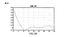
図8A〜図8Dに、ユーザの指がマイクロフォンから離れて移動する状況について実行された相関のシミュレーション結果を示す。図8Aは、0度で式4を適用したことによる相関結果を示している。図8Bは、90度で式4を適用したことによる相関結果を示している。図8Cは、45度で式4を適用したことによる相関結果を示している。図8Dは、135度で式4を適用したことによる相関結果を示している。上記度数は、次のようにフィルタ係数の勾配変化の方向を示す。
FIGS. 8A-8D show the simulation results of the correlations performed for the situation where the user's finger moves away from the microphone. FIG. 8A shows the correlation result from applying
0度=[−1 0 1;−1 1 1;−1 0 1]
90度=[1 1 1;0 1 0;−1 −1 −1]
45度=[0 1 1;−1 1 1;−1 −1 0]
135度=[1 1 0;1 1 −1;0 −1 −1]
図9Aに、ユーザの指がマイクロフォンから離れて移動する状況について実行された角度2次相関のシミュレーション結果を示す。
0 degrees = [-1 0 1; -1 1 1; -1 0 1]
90 degrees = [1 1 1; 0 1 0; -1 -1 -1]
45 degrees = [0 1 1; -1 1 1; -1 -1 0]
135 degrees = [1 1 0; 1 1 −1; 0 −1 −1]
FIG. 9A shows the simulation result of the angular quadratic correlation performed for the situation where the user's finger moves away from the microphone.
図9Bに、ユーザの指がマイクロフォンから離れて移動する状況について実行された逆差分行列相関のシミュレーション結果を示す。 FIG. 9B shows the simulation result of the inverse difference matrix correlation executed for the situation where the user's finger moves away from the microphone.
図9Cに、ユーザの指がマイクロフォンから離れて移動する状況について実行された差分エントロピー相関のシミュレーション結果を示す。 FIG. 9C shows the simulation result of the differential entropy correlation performed for the situation where the user's finger moves away from the microphone.
さらなる実施形態では、周波数領域特徴も抽出され得る。この実施形態では、差分チャネルインパルス応答画像に2次元高速フーリエ変換(FFT)を適用することによって電力スペクトル密度が取得され得る。電力スペクトル密度は、反射体が受信機に向かって移動するときは、より多くの低周波成分を示し、反射体が受信機から離れて移動するときは、より多くの高周波成分を示し得、したがって、ユーザ入力ジェスチャーを認識またはカテゴリー分類するために使用され得るさらなる情報を与え得る。 In further embodiments, frequency domain features may also be extracted. In this embodiment, the power spectral density can be obtained by applying a two-dimensional fast Fourier transform (FFT) to the differential channel impulse response image. The power spectral density can show more low frequency components when the reflector moves towards the receiver and can show more high frequency components when the reflector moves away from the receiver, and thus , May provide additional information that may be used to recognize or categorize user input gestures.
さらなる実施形態では、インパルス応答波方向を識別するためにFFT結果のリングおよびウェッジサンプリング(ring and wedge sampling)が使用され得る。リングおよびウェッジサンプリングは、反射検出ゾーンの中心から延びる一連の放射状に配列された半環状領域およびウェッジ領域にわたって行われ得る。半円形リングエリアのサンプリングは、差分チャネルインパルス応答画像における空間周波数の分布に関する配向非依存情報を与え得、角度ウェッジエリアのサンプリングは、スケール非依存情報を与え得る。 In a further embodiment, ring and wedge sampling of FFT results may be used to identify the impulse response direction. Ring and wedge sampling can be performed over a series of radially arranged semi-annular and wedge regions extending from the center of the reflection detection zone. Sampling of the semi-circular ring area may provide orientation independent information regarding the distribution of spatial frequencies in the differential channel impulse response image, and sampling of the angular wedge area may provide scale independent information.
3D空間における最も強い反射点のロケーションを判断するために使用され得る飛行時間計算を行う際に使用するための最も強い反射点を識別するために、差分チャネルインパルス応答画像の分類が使用され得る。飛行時間は、識別された反射点について計算され得る。送信機といくつかの受信機が、同じシステムクロックに同期され、それにより、超音波送信のタイムスタンピングの必要がなくなり得る。したがって、各受信機についての飛行時間測定値は、単に、信号の送信時間と、一致した信号についての受信時間との差分であり得る。 A classification of the differential channel impulse response image can be used to identify the strongest reflection point for use in performing time-of-flight calculations that can be used to determine the location of the strongest reflection point in 3D space. The time of flight can be calculated for the identified reflection points. The transmitter and several receivers may be synchronized to the same system clock, thereby eliminating the need for time stamping for ultrasonic transmission. Thus, the time of flight measurement for each receiver can simply be the difference between the signal transmission time and the reception time for the matched signal.
3次元空間における反射点の座標を判断するために飛行時間値が使用され得る。座標は、送信機、受信機または何らかの他のロケーションにおける、原点を用いた基準系における座標であり得る。原点に対する受信機の座標は、以前から知られているかまたは判断され得る。反射点の座標は、超音波速度に基づいて3つ以上の受信機の飛行時間値を距離に変換することと、楕円交点方法においてその距離を使用することとによって判断され得る。チャネル状態は、各測定間の短い期間において大幅に変動する可能性がないので、音速は定数aとして仮定され得るが、その定数は、変化するチャネル状態において経時的に調整される必要があり得る。以下の式が使用され得、ここで、x,y,zは反射座標であり、mx1,my1,mz1はmic1の座標であり、また、0,0,0は、スピーカー座標である。
反射座標を判断するために使用されるべき飛行時間値は雑音が多いことがある。これに対処するために、ノイジネスを克服し、反射座標を判断するために、カルマンフィルタが使用され得る。非線形システムの場合、拡張カルマンフィルタ(EKF)または「アンセンテッドカルマンフィルタ」が使用され得る。カルマンフィルタは、予測値と測定値とを重み付けし、組み合わせることによって、測定値と計算される推定値との真値を予測する。カルマンフィルタは、値を予測し、予測値の不確実性を推定し得る。カルマンフィルタプロセスは、より高い重みがより確実な値に行くように、不確実性に基づいて予測値に重み付けを割り当て、次いで、測定値を用いて重み付き平均を計算し得る。このようにして、雑音の多い測定値は、重み付き平均が予測値または測定値のいずれかよりも良い推定された不確実性を有するので、真値により近くなるように調整され得る。 The time-of-flight value to be used to determine the reflection coordinates can be noisy. To address this, a Kalman filter can be used to overcome noisiness and determine the reflection coordinates. For nonlinear systems, an extended Kalman filter (EKF) or “uncented Kalman filter” may be used. The Kalman filter predicts the true value of the measured value and the calculated estimated value by weighting and combining the predicted value and the measured value. The Kalman filter can predict the value and estimate the uncertainty of the predicted value. The Kalman filter process may assign a weight to the predicted value based on the uncertainty so that the higher weight goes to a more certain value, and then use the measured value to calculate a weighted average. In this way, the noisy measurement can be adjusted to be closer to the true value because the weighted average has an estimated uncertainty that is better than either the predicted value or the measurement.
図10A〜図10Cに、3つのマイクロフォンをもつコンピュータデバイスの表面の約1cm上方で空中に浮いているユーザの指のシミュレーションにおいて生成されたデータのカルマンフィルタ処理の結果を示す。図10Aは、第1のマイクロフォンについてのシミュレーションチャネルインパルス応答対時間結果を示している。図10Bは、第2のマイクロフォンについてのシミュレーションチャネルインパルス応答対時間結果を示している。図10Cは、第3のマイクロフォンについてのシミュレーションチャネルインパルス応答対時間結果を示している。上記マイクロフォンは、コンピューティングデバイス上の異なるロケーションに位置するので、異なるチャネルインパルス応答を示している。 FIGS. 10A-10C show the results of Kalman filtering of data generated in a simulation of a user's finger floating in the air approximately 1 cm above the surface of a computing device with three microphones. FIG. 10A shows the simulated channel impulse response versus time result for the first microphone. FIG. 10B shows the simulated channel impulse response versus time result for the second microphone. FIG. 10C shows the simulated channel impulse response versus time result for the third microphone. Since the microphones are located at different locations on the computing device, they exhibit different channel impulse responses.
カルマンフィルタ処理された結果を使用して、最大チャネルインパルス応答値、インデックス、および最大信号までの距離が判断され得る。図11Aに、すべての3つのマイクロフォンについての、図10A〜図10Cに示す処理から判断されたチャネルインパルス応答の最大振幅対時間を示す。図11Bに、すべての3つのマイクロフォンについての、図10A〜図10Cに示す処理から判断されたチャネルインパルス応答のインデックス値対時間を示す。図11Cに、すべての3つのマイクロフォンについての、図10A〜図10Cに示す処理から判断された最大インデックスにおける測定値の振幅対時間を示す。 Using the Kalman filtered result, the maximum channel impulse response value, the index, and the distance to the maximum signal can be determined. FIG. 11A shows the maximum amplitude of channel impulse response versus time determined from the process shown in FIGS. 10A-10C for all three microphones. FIG. 11B shows the channel impulse response index value versus time determined from the processing shown in FIGS. 10A-10C for all three microphones. FIG. 11C shows the measured amplitude versus time at the maximum index determined from the process shown in FIGS. 10A-10C for all three microphones.
ジェスチャー特徴が定義されると、分類器をトレーニングするためにトレーニングデータセット(ジェスチャー特徴)が使用され得る。分類器は、単純なKNN分類器、あるいはより複雑なANNまたはHMMモデルであり得る。上記の分析方法によって抽出された特徴が、ユーザトレーニングシーケンスにおいて定義され得るような特定のユーザ入力ジェスチャーと相関され得る。チャネルインパルス応答から抽出されたパターンをメモリに記憶されたパターンと比較するために、よく知られているパターン比較または相関方法が使用され得る。この目的で使用され得る相関方法の3つの例は、k最近傍(k-nearest neighbor)アルゴリズム、人工ニューラルネットワーク分析、および隠れマルコフモデル(hidden Markov model)である。人工ニューラルネットワークまたは隠れマルコフモデルは、学習段階において前にトレーニングされていることがある。これらの3つの例示的な相関方法について以下でより詳細に説明するが、他の相関方法も同様にして使用され得る。 Once the gesture features are defined, a training data set (gesture features) can be used to train the classifier. The classifier can be a simple KNN classifier or a more complex ANN or HMM model. Features extracted by the above analysis methods can be correlated with specific user input gestures as can be defined in a user training sequence. Well known pattern comparison or correlation methods may be used to compare the pattern extracted from the channel impulse response with the pattern stored in memory. Three examples of correlation methods that can be used for this purpose are the k-nearest neighbor algorithm, the artificial neural network analysis, and the hidden Markov model. Artificial neural networks or hidden Markov models may have been previously trained in the learning phase. These three exemplary correlation methods are described in more detail below, but other correlation methods may be used as well.
k最近傍アルゴリズムは、ある数、すなわちk個の最も近いネイバーの多数決によってオブジェクトを分類する。ネイバーが、すでに正しく分類されたオブジェクトのセットから取り出され、この場合、これは差分チャネルインパルス応答画像から抽出されたパターンである。どの分類されたオブジェクトまたはネイバーが最も近いかを定義するルールが設定される。たとえば、一定の特徴または座標の変化が、ネイバーであり、前もって一定のジェスチャーに分類されるかまたはそれらと相関され得る。分類されるべき、差分チャネルインパルス応答画像から抽出されたパターンが、一定のネイバーに近い値で抽出された特徴を有し得る。選択されたパラメータkに応じて、いくつかのネイバーが比較され得る。kが5に等しい場合、最も近い特徴値をもつ5つの近傍パターンは、差分チャネルインパルス応答画像から抽出されたパターンが何として分類されるかを判断し得る。5つのネイバーの大部分が一定のジェスチャーと相関される場合、差分チャネルインパルス応答画像から抽出されたパターンは、上記大部分と同じジェスチャーと相関され得る。そのような比較アルゴリズムを使用して、近さまたは他の1つまたは複数の性質によって、ネイバーの票を重み付けすることが可能である。 The k-nearest neighbor algorithm classifies objects by a certain number, that is, the majority of k nearest neighbors. Neighbors are taken from a set of already correctly classified objects, in this case this is a pattern extracted from the differential channel impulse response image. A rule is set that defines which classified object or neighbor is closest. For example, certain feature or coordinate changes may be neighbors and may be classified in advance or correlated with certain gestures. The pattern extracted from the differential channel impulse response image to be classified may have features extracted at a value close to a certain neighbor. Depending on the selected parameter k, several neighbors can be compared. If k is equal to 5, the five neighboring patterns with the closest feature values can determine what the pattern extracted from the differential channel impulse response image is classified as. If the majority of the five neighbors are correlated with a certain gesture, the pattern extracted from the differential channel impulse response image can be correlated with the same gesture as the majority. Using such a comparison algorithm, it is possible to weight neighbor votes by proximity or one or more other properties.
人工ニューラルネットワークは、学習段階中にネットワーク中を流れる情報に基づいて構造を変更し得る人工ニューロンの相互接続されたグループとして機能するオブジェクトの計算を使用する比較方法である。ニューラルネットワーク中の接続は、強度または重み付けにおいて異なり得る。各人工ニューロンは単純な処理ノードまたは機能であり得るが、全体としてのネットワークは複雑な挙動を示し得る。人工ニューラルネットワークは、あらかじめ定義されたコスト関数に従って最適が測定されるタスクに対して最適解を見つけるために観測値のセットを使用することによって学習し得る。たとえば、学習段階中に、ユーザは、いくつかの観測値が取得され得るように、特定のユーザ入力ジェスチャーを何回か実行するように依頼され得る。差分チャネルインパルス応答画像から抽出された観測値またはパターンが、ニューラルネットワークに供給され、様々なノードおよび接続を通って、解が生成され得る。ニューラルネットワークによって生成された解は、コスト関数に従ってランク付けされ得る。このランク付けに基づいて、接続の重み付けが調整され得る。適切にトレーニングされると、ニューラルネットワークの重み付け値は固定され得る。ニューラルネットワークは、差分チャネルインパルス応答画像から抽出されたパターンを比較して、それらのパターンをトレーニングセッションから学習することによって、ジェスチャーのパターン認識または分類のために使用され得る。解は、いくつかのユーザ入力ジェスチャーに類似し得る。特徴または座標の変化が、前にトレーニングされたニューラルネットワークのための入力として働き得、その場合、そのニューラルネットワークは、ニューラルネットワーク構造に基づいて、その入力を解またはジェスチャーと接続することになる。ニューラルネットワークは、学習段階において既知のジェスチャーまたは特徴を用いて前にトレーニングされていることがある。 Artificial neural networks are a comparative method that uses the computation of objects that function as interconnected groups of artificial neurons that can change structure based on information flowing through the network during the learning phase. Connections in the neural network can differ in strength or weighting. Each artificial neuron can be a simple processing node or function, but the network as a whole can exhibit complex behavior. An artificial neural network can learn by using a set of observations to find an optimal solution for a task whose optimality is measured according to a predefined cost function. For example, during the learning phase, the user may be asked to perform certain user input gestures several times so that several observations can be obtained. Observations or patterns extracted from the difference channel impulse response image can be fed into a neural network and solutions can be generated through various nodes and connections. The solutions generated by the neural network can be ranked according to a cost function. Based on this ranking, the connection weights can be adjusted. When properly trained, the neural network weight values can be fixed. Neural networks can be used for pattern recognition or classification of gestures by comparing patterns extracted from differential channel impulse response images and learning those patterns from a training session. The solution may be similar to some user input gestures. Changes in features or coordinates can serve as input for a previously trained neural network, in which case the neural network will connect that input with a solution or gesture based on the neural network structure. Neural networks may have been previously trained using known gestures or features during the learning phase.
隠れマルコフモデルは、モデル化されているシステムが、状態は未知であるが、状態に依存するトークンは既知である、マルコフ過程であると仮定する。マルコフ過程は、状態が経時的に変動する過程であって、将来の状態が、現在の状態のみに依存し、前の状態には依存しない、過程である。あり得る各状態は、あり得るトークンにわたる確率分布と、どの状態が次に来ることになるかに関する確率分布とを有する。したがって、それらのトークンは、この過程における状態のシーケンスに関する何らかの情報を与える。ジェスチャー認識では、状態は、ユーザ入力ジェスチャーに関連する類似する特徴であり得、また、トークンは、差分チャネルインパルス応答画像から抽出されたパターンと類似し得る。トークンにわたる、状態間の確率分布は、あらかじめ定義されたパラメータであるか、または学習段階において設定されることがある。学習段階においてモデルのパラメータ値をトレーニングし、展開するために、既知のジェスチャーまたは特徴の差分チャネルインパルス応答画像から抽出されたパターンが入力され得る。ビタビアルゴリズムなどによって、トレーニングされた隠れマルコフモデルから、状態またはジェスチャーの最も可能性のあるシーケンスが再帰的に判断され得る。 The hidden Markov model assumes that the system being modeled is a Markov process whose state is unknown but tokens that depend on the state are known. The Markov process is a process in which the state changes with time, and the future state depends only on the current state and does not depend on the previous state. Each possible state has a probability distribution over the possible tokens and a probability distribution as to which state will come next. These tokens therefore give some information about the sequence of states in this process. In gesture recognition, the state can be a similar feature associated with a user input gesture, and the token can be similar to a pattern extracted from a differential channel impulse response image. The probability distribution between states across tokens may be a predefined parameter or set during the learning phase. A pattern extracted from a differential channel impulse response image of a known gesture or feature can be input to train and develop model parameter values in the learning phase. The most likely sequence of states or gestures can be recursively determined from the trained hidden Markov model, such as by a Viterbi algorithm.
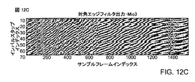
さらなる実施形態では、反射体の移動方向を識別することなど、単純なジェスチャー認識タスクが、インパルス応答曲線から直接導出された角度特徴を使用して達成され得る。図12A〜図16Cに、異なる反射体移動についてのインパルス応答パターンと、それらの対応する応答曲線角度情報が、どのように認識され得るかを示す。 In further embodiments, simple gesture recognition tasks, such as identifying the direction of movement of the reflector, can be accomplished using angular features derived directly from impulse response curves. FIGS. 12A-16C illustrate how the impulse response patterns for different reflector movements and their corresponding response curve angle information can be recognized.
3つのマイクロフォンに向かって移動する指の存在下でのプロトタイプにおけるそれらのマイクロフォンの各々についてのインパルス応答判断のグラフを図12A〜図12Cに示す。これらの図は、対角エッジフィルタで処理した後の未加工インパルス応答判断を示している。これらの図でわかるように、マイクロフォンに向かうユーザの指の動きにより、サンプルフレームインデックスに示すように、時間によって変わるインパルス応答判断において角度が知覚でき得る。 Graphs of impulse response decisions for each of those microphones in the prototype in the presence of a finger moving toward three microphones are shown in FIGS. 12A-12C. These figures show the raw impulse response determination after processing with a diagonal edge filter. As can be seen from these figures, the movement of the user's finger toward the microphone can perceive the angle in the time-dependent impulse response determination, as shown in the sample frame index.
未加工インパルス応答判断は現実の認識可能な特徴を用いて行われるが、そのような特徴は、ブロックチャネルインパルス応答上で低域フィルタを使用して信号を処理することによって強調され得る。値1の5×5行列の形態の低域フィルタの一例は以下の通りである。
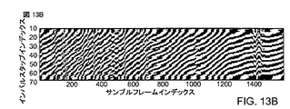
ループ低域フィルタで処理した後の、3つのマイクロフォンに向かって移動する指の存在下でのプロトタイプにおけるそれらのマイクロフォンの各々についてのインパルス応答判断のグラフを図13A〜図13Cに示す。これらの図は、インパルス応答に低域フィルタを適用することにより、インパルス応答の角度を判断するために使用され得るより明確なパターンが与えられることを明らかにしている。 Graphs of impulse response determination for each of those microphones in the prototype in the presence of a finger moving towards three microphones after processing with a loop low pass filter are shown in FIGS. 13A-13C. These figures reveal that applying a low pass filter to the impulse response gives a clearer pattern that can be used to determine the angle of the impulse response.
インパルス応答におけるパターンの角度が容易に判断され得るので、この角度は特定の移動にリンクされ得る認識可能な特徴として使用され得る。たとえば、90度よりも小さい角度は、反射体(たとえば、ユーザの手または指)がマイクロフォンに近づいていることを意味し得、90度から180度の間の角度は、反射体がマイクロフォンから遠ざかっていることを意味し得る。その場合、そのようなユーザ移動は、単純なテーブルルックアップ方法を使用して特定のユーザインターフェースコマンド(たとえば、マウスポインタ移動)に相関され得る。 Since the angle of the pattern in the impulse response can be easily determined, this angle can be used as a recognizable feature that can be linked to a particular movement. For example, an angle less than 90 degrees may mean that a reflector (eg, a user's hand or finger) is approaching the microphone, and an angle between 90 and 180 degrees is that the reflector is away from the microphone. Can mean that. In that case, such user movement may be correlated to a specific user interface command (eg, mouse pointer movement) using a simple table lookup method.
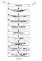
図14に、インパルス応答の角度を判断することに基づいて反射検出ゾーン内のユーザの手から反射される超音波からユーザ入力ジェスチャーを認識するためにコンピューティングデバイスにおいて実行され得る実施方法450を示す。方法450では、ステップ452において、プロセッサが、擬似ランダム雑音または擬似乱数コード、あるいは他の時間符号化情報を生成し、ステップ454において、パルス圧縮とともにスペクトル拡散変調において、その情報を符号化し得る。次いで、ステップ456において、この符号化された信号を超音波放出器から持続波超音波として放出する。ステップ458において、反射およびクロストーク信号を含む、超音波を超音波検出器において受信する。ステップ460において、プロセッサ(たとえば、DSP)が、受信した超音波信号に基づいてチャネルインパルス応答を計算し得る。ステップ460の一部として、プロセッサは、上記で説明した方法を使用して、反射チャネルインパルス応答を取得するためにベースラインチャネルインパルス応答を減算し得る。ステップ462において、コンピューティングデバイスプロセッサは、上記で説明した計算方法を使用して、経時的な差分チャネルインパルス応答を計算し、一連のそれらの値を差分チャネルインパルス応答画像として維持し得る。また、ステップ462の一部として、コンピューティングデバイスプロセッサは、計算された差分インパルス応答にエッジフィルタ、低域フィルタおよびしきい値処理演算を適用し得る。ステップ464において、プロセッサは、様々なフィルタ処理角度をもつ矩形フィルタを選択し得る。ステップ466において、プロセッサは、矩形フィルタ全体をカバーすることができる一定数のサンプルフレームを含んでいるチャネルインパルス応答の領域を選択し得る。ステップ468において、プロセッサは、その領域内でフィルタを移動しながら、フィルタ内のすべての点の合計の最大値を計算するためにフィルタ内の点を合計し得る。ステップ470において、プロセッサは、選択された矩形フィルタの各角度についてステップ466および468を繰り返し得る。フィルタの角度のすべてが処理されると、ステップ472において、プロセッサは、全インパルス応答行列にわたって領域が選択された後に、各フレームについてインパルス応答曲線の角度を判断し得る。ステップ474において、プロセッサは、インパルス応答曲線の判断された角度に対応するユーザ入力コマンドを実行する。ステップ474の一部として、コンピューティングデバイスは、他のユーザインターフェースシステムと同様の方法で、実行されたユーザ入力コマンドに対応するユーザインターフェース画像を表示し得る。
FIG. 14 illustrates an
ステップ472においてインパルス応答曲線の角度を判断することは、以下の式を利用し得る。
上式で、p(n,t)は、図13A〜図13Cのうちのいずれかの中の点(n,t)におけるインパルス応答の振幅であり、また、(t0,tmax,M)は矩形フィルタのサイズである。その場合、角度は、Rectiの最大引数として判断され得る。言い換えれば、角度=argmax(Recti)であり、ここで、i=1:Nである。Nは、等しく分割された角度の数であり、また、各角度の増分ステップはπ/Nである。 In the above equation, p (n, t) is the amplitude of the impulse response at the point (n, t) in any one of FIGS. 13A to 13C, and (t0, tmax, M) is a rectangle. The size of the filter. In that case, the angle may be determined as the maximum argument of Rect i . In other words, angle = argmax (Rect i ), where i = 1: N. N is the number of equally divided angles and the increment step for each angle is π / N.
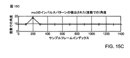
これらの方法を使用してユーザ入力ジェスチャーを認識するプロセスの一部として、図15A〜図15Cに示すように、インパルス応答曲線の角度が経時的にプロットされ得る。これらの図は、ユーザの指がシステムの3つのマイクロフォンに向かって移動している場合の、サンプルフレームインデックスによって変わる、度数でのインパルスパターンの検出された角度の変化を示している。 As part of the process of recognizing user input gestures using these methods, the angle of the impulse response curve may be plotted over time, as shown in FIGS. 15A-15C. These figures show the change in the detected angle of the impulse pattern in degrees, depending on the sample frame index, when the user's finger is moving towards the three microphones of the system.
すべての3つのマイクロフォンからのインパルス応答曲線の導出された角度により、3D空間における反射体移動方向を一意に判断することができる。図15A〜図15Cに示すように、3つのマイクロフォンがコンピューティングデバイス上でまたはそれの近傍で異なるロケーションに位置するとき、経時的な角度の変化は、それらのマイクロフォンの各々について異なることになる。反射体が、2つのマイクロフォンを結ぶ線に対して平行に移動しているとき、反射体移動の方向を判断するために、それらの2つのマイクロフォンが使用され得る。 With the derived angles of the impulse response curves from all three microphones, the reflector movement direction in 3D space can be uniquely determined. As shown in FIGS. 15A-15C, when three microphones are located at different locations on or near the computing device, the change in angle over time will be different for each of those microphones. When the reflector is moving parallel to the line connecting the two microphones, the two microphones can be used to determine the direction of reflector movement.
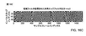
この方法は、図16A〜図17Cに示すように、システムマイクロフォンに向かっておよびそれから離れて移動するユーザの指など、より複雑なユーザ入力ジェスチャーを認識するために使用され得る。たとえば、図16A〜図16Cは、ループ低域フィルタで処理した後の、3つのマイクロフォンに向かって、次いでそれらから離れて移動する指の存在下でのプロトタイプにおけるそれらのマイクロフォンの各々についてのインパルス応答判断をグラフで示している。これらの図は、ユーザの指が、マイクロフォンに向かって移動し、次いでそれから離れて移動し、次いでそれに向かって移動するにつれて、インパルス応答曲線の角度が、どのように第1の値から第2の値に変化し、次いで元どおりになるかを明らかにしている。図17A〜図17Cは、システムにおける3つのマイクロフォンの各々についての、図16A〜図16Cに示すインパルス応答曲線についてのインパルス応答曲線の角度をグラフで示している。 This method can be used to recognize more complex user input gestures, such as a user's finger moving toward and away from the system microphone, as shown in FIGS. 16A-17C. For example, FIGS. 16A-16C show the impulse response for each of those microphones in the prototype in the presence of a finger moving toward and then away from the three microphones after processing with a loop low-pass filter. Judgment is shown in a graph. These figures show how the angle of the impulse response curve changes from the first value to the second as the user's finger moves towards the microphone, then away from it, and then towards it. It is clear whether it changes to a value and then returns. 17A-17C graphically illustrate the angle of the impulse response curve for the impulse response curve shown in FIGS. 16A-16C for each of the three microphones in the system.
実施分析方法では、反射体を画像化することがジェスチャー認識のために必要でないので、受信された超音波を復調する必要を回避しながらジェスチャー認識が可能になる。超音波は、送信機からの情報のキャリアとしてではなく、むしろ反射体(すなわち、ユーザの手)に関する情報のコレクタとして働き、その情報は、反射検出ゾーン内のいずれかの反射表面による影響を受けるチャネルインパルス応答の形態で抽出される。チャネル応答のパターンおよび特徴に依拠することによって、実施方法は、ユーザの手などの反射表面の画像を解像または形成するデータ集約的プロセスを回避する。代わりに、ジェスチャー認識は、反射データをマッピングする必要なしに、またはチャネルが何であるかを判断する必要なしに、チャネルインパルス応答の変化に依拠することによって、達成される。 In an implementation analysis method, imaging the reflector is not necessary for gesture recognition, so gesture recognition is possible while avoiding the need to demodulate the received ultrasound. The ultrasound acts as a collector of information about the reflector (ie, the user's hand) rather than as a carrier of information from the transmitter, and that information is affected by any reflective surface in the reflection detection zone. Extracted in the form of a channel impulse response. By relying on channel response patterns and features, the implementation method avoids a data intensive process of resolving or forming an image of a reflective surface, such as a user's hand. Instead, gesture recognition is achieved by relying on changes in the channel impulse response without having to map reflection data or having to determine what the channel is.
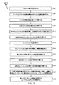
図18に、反射検出ゾーン内のユーザの手から反射される超音波からユーザ入力ジェスチャーを認識するためにコンピューティングデバイスにおいて実行され得る実施方法500を示す。方法500では、ステップ502において、プロセッサが、擬似ランダム雑音または擬似乱数コード、あるいは他の時間符号化情報を生成し、ステップ504において、パルス圧縮とともにスペクトル拡散変調において、その情報を符号化し得る。次いで、ステップ506において、この符号化された信号を超音波放出器から持続波超音波として放出する。ステップ508において、反射およびクロストーク信号を含む、超音波を超音波検出器において受信する。ステップ510において、プロセッサ(たとえば、DSP)が、受信した超音波信号に基づいてチャネルインパルス応答を計算し得る。ステップ510の一部として、プロセッサは、上記で説明した方法を使用して、反射チャネルインパルス応答を取得するためにベースラインチャネルインパルス応答を減算し得る。ステップ512において、コンピューティングデバイスプロセッサは、上記で説明した計算方法を使用して、経時的な差分チャネルインパルス応答を計算し、一連のそれらの値を差分チャネルインパルス応答画像として維持し得る。ステップ514において、プロセッサは、認識可能な特徴を強調するために差分チャネルインパルス応答画像にエッジフィルタを適用し得る。ステップ516において、プロセッサは、エッジフィルタ処理された差分チャネルインパルス応答画像から認識可能な特徴を抽出するためにグレーレベル共分散行列を計算し得る。ステップ518において、プロセッサは、一致する記録を識別するために、エッジフィルタ処理された差分チャネルインパルス応答画像から抽出された特徴を、ユーザジェスチャーに関連するデータベースに記憶されたパターンと比較し得る。上記で説明したように、ステップ518は、コンピューティングデバイスにおける我々の現在の動作状態またはアプリケーション、あるいは他の状態関係の考慮事項に関係する、ジェスチャーのパターンを比較することを伴い得る。ステップ518における処理は、k最近傍、人工ニューラルネット、および隠れマルコフモデルなど、相関方法を使用し得る。ステップ518の結果は、一致したジェスチャーパターンに関連する識別されたユーザ入力コマンドであり得る。ステップ520において、コンピューティングデバイスは、一致したパターンに関連する識別されたユーザコマンドを実行し得る。ステップ520の一部として、コンピューティングデバイスは、他のユーザインターフェースシステムと同様の方法で、認識されたジェスチャーに対応するユーザインターフェース画像を表示し得る。
FIG. 18 illustrates an
図18に示すプロセスは、ユーザが特定のジェスチャーを実行するように促され得ることと、ステップ518において抽出された特徴を比較する代わりに、プロセッサが抽出された特徴をデータベースに記憶し得ることとを除いて、トレーニングシーケンスにおいても使用され得る。
The process shown in FIG. 18 can prompt the user to perform a particular gesture, and instead of comparing the features extracted in
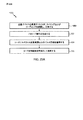
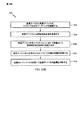
図19に、反射物体を識別し、その物体の動きを認識するために、方法500の特徴抽出および相関ステップが使用され得る、代替実施方法600を示す。方法500の場合のように、ステップ502〜506において、時間的に符号化された超音波信号を生成し、放出し得る。ステップ508〜512において、差分チャネルインパルス応答画像を取得するために、超音波信号とユーザの手からの反射とを受信し、処理し得る。ステップ514〜516において、認識可能な特徴を抽出するために、差分チャネルインパルス応答画像を、エッジフィルタ処理し、グレーレベル共分散行列を用いて分析し得る。
FIG. 19 illustrates an
方法500とは異なり、方法600では、ステップ618において、抽出された特徴を使用して、飛行時間計算のための当該の反射点を識別し得る。抽出された特徴に基づく当該の点の選択は、ステップ516において使用されるのと同じ相関方法に依拠し得る。これらの方法は、抽出された特徴を相関させ、強い1次または2次反射体を示すために、使用され得る。強い反射の適切なグルーピングに伴って、1次反射体は、主要な反射体として区別され、識別され得る。ステップ620において、識別された主要な反射点から反射される信号の送信と受信とからの時間差を計算することによって、飛行時間値を判断し得る。ステップ622において、飛行時間値におけるノイジネスを克服するために、カルマンフィルタ処理を含む、上記で説明したのと同じ方法および式を用いて、識別された反射点の座標を計算し得る。ステップ624において、識別された反射点の座標を経時的に追跡し、ステップ624において、座標の変化を計算し、(場合によっては)ユーザ入力ジェスチャーと相関させ得る。ステップ626において、コンピューティングデバイスは、一致したパターンに関連する識別されたユーザコマンドを実行する。ステップ626の一部として、コンピューティングデバイスは、他のユーザインターフェースシステムと同様の方法で、ステップ620〜622において判断された3D空間内の認識されたジェスチャーのロケーションを含む、認識されたジェスチャーに対応するユーザインターフェース画像を表示し得る。
Unlike
図19に示すプロセスは、ユーザが特定のジェスチャーを実行するように促され得ることと、ステップ624において抽出された特徴を比較する代わりに、プロセッサが抽出された特徴をデータベースに記憶し得ることとを除いて、トレーニングシーケンスにおいても使用され得る。
The process shown in FIG. 19 can prompt the user to perform a specific gesture, and instead of comparing the features extracted in
超音波放出器101と、マイクロフォン102a、102b、および102cとについての例示的な位置を含む、様々な実施形態とともに使用するのに好適なラップトップコンピュータ700の形態の例示的なコンピューティングシステムを図20に示す。多くのラップトップコンピュータは、コンピュータのポインティングデバイスとして働くタッチパッドタッチ面を含む。ラップトップコンピュータ700は、一般に、揮発性メモリ702と、ディスクドライブ703などの大容量不揮発性メモリとに結合されたプロセッサ701を含むものである。コンピュータ700は、プロセッサ701に結合されたフロッピー(登録商標)ディスクドライブ704とコンパクトディスク(CD)ドライブ705とをも含み得る。コンピュータデバイス700は、USBまたはFireWire(登録商標)コネクタソケットなど、データ接続を確立することまたは外部メモリデバイスを受けることを行うための、プロセッサ701に結合されたいくつかのコネクタポート、あるいはプロセッサ701をネットワークに結合するための他のネットワーク接続回路706をも含み得る。ノートブック構成では、コンピュータハウジングは、プロセッサ701にすべて結合された、タッチパッド707と、キーボード708と、ディスプレイ709とを含む。
1 illustrates an exemplary computing system in the form of a laptop computer 700 suitable for use with various embodiments, including exemplary locations for the
超音波送信機101および受信機/マイクロフォン102a〜102cは、飛行時間差に基づく3D座標計算を可能にするように選択された、システムハウジング上のロケーションにおいて、ラップトップコンピュータ700と一体化され得る。いくつかの実施形態では、超音波送信機101および受信機/マイクロフォン102a〜102cは、他のオーディオ機能のためのコンピューティングデバイススピーカーおよびマイクロフォンとしても働き得る。実施システムまたは実施方法によって判断されたジェスチャーは、コンピュータ700のための入力として働き得、コンピュータ700上のプログラムを制御すること、またはグラフィカルユーザインターフェースと対話することを行うために使用され得る。様々な実施形態では、超音波タッチレス感知能力は、タッチパッド707またはキーボード708を増強するか、またはそれに取って代わり得る。
The
また、セルフォンまたはPDAなどのモバイルデバイスが、様々な実施形態を使用するように構成され得る。様々な実施形態とともに使用するのに好適な典型的なモバイルデバイス800が、図21に示す構成要素を含み得る。たとえば、例示的なモバイル受信機デバイス800は、内部メモリ802とディスプレイ803とスピーカー809とに結合されたプロセッサ801を含み得る。さらに、モバイルデバイス800は、電磁放射を送信および受信するためのアンテナ804を有し得、アンテナ804は、プロセッサ801に結合されたワイヤレスデータリンクおよび/またはセルラー電話トランシーバ805、ならびに/あるいはプロセッサ801に結合されたモバイルマルチメディアブロードキャスト受信機808に接続される。モバイルデバイスは、一般に、ユーザ入力を受け取るためのキーパッド806または小型キーボードおよびメニュー選択ボタンまたはロッカースイッチ807をも含む。これらの入力に加えて、モバイルデバイス800は、タッチレスユーザインターフェースのための実施形態を用いて増強され得る。モバイルデバイス800は、超音波を放出するためにスピーカー804を使用するか、または超音波送信機101などの別個の超音波放出器を組み込み得る。モバイルデバイスは、1つまたは複数の受信機/マイクロフォン102a〜102cを通して、反射または他のモバイルデバイスなどから、超音波を受信し得る。
In addition, mobile devices such as cell phones or PDAs can be configured to use various embodiments. An exemplary
プロセッサ701、801は、本明細書で説明する様々な実施形態の機能を含む、様々な機能を実行するようにソフトウェア命令(アプリケーション)によって構成され得る任意のプログラマブルマイクロプロセッサ、マイクロコンピュータあるいは1つまたは複数の多重プロセッサチップであり得る。一部のモバイルデバイスでは、別個のプロセッサ304など、1つのプロセッサをワイヤレス通信機能専用とし、1つのプロセッサを他のアプリケーションの実行専用とするなど、複数のプロセッサ701、801を設け得る。一般に、ソフトウェアアプリケーションは、アクセスされ、プロセッサ801にロードされる前に、内部メモリ702、802に記憶され得る。一部のモバイルデバイスでは、プロセッサ701、801は、アプリケーションソフトウェア命令を記憶するのに十分な内部メモリを含み得る。本明細書では、メモリへの一般的言及は、内部メモリ702、703、704、802と、デバイスに接続されるリムーバブルメモリと、プロセッサ701、801自体の内部のメモリとを含む、プロセッサ701、801によってアクセス可能なすべてのメモリを指す。
The
さらなる実施形態は、一緒に動作する超音波放出要素と超音波受信要素とで構成された複数のデバイスを伴い得る。図22に示す例示的なシステム900に示すように、2つのモバイルデバイス800a、800bが持続波超音波を介して対話し得る。デバイス800a、800bは、空間において互いの近くに位置し得る。各デバイスは、それ自体の放出器101および受信機102を含み得るが、デバイス800a、800bは、一方のデバイス800aは、デバイスの放出器101がアクティブであり持続波超音波206を放出する、送信モードで動作し、他方のデバイス800bは、デバイスの受信機102a、102b、および102cを介して持続波超音波206を受信する、受信モードにあるように、構成され得る。様々な実施形態に従って持続波超音波206を受信し、処理することによって、受信モードデバイス800bは、放出デバイス800aまでの距離および放出デバイス800aへの方向を判断することができる。
Further embodiments may involve a plurality of devices composed of an ultrasound emitting element and an ultrasound receiving element that work together. As shown in the
実施形態は、放出器デバイス800aと受信機デバイス800bとの間の相対座標、または放出器デバイス800aから受信機デバイス800bまでの距離を判断するための方法をさらに含む。送信モードで動作するモバイルデバイス800a上に実行され得る実施方法1000を図23Aに示す。方法1000では、ステップ1002において、2つのデバイスは、通信して、役割を調整し、タイミングとコーディングとに関する情報を共有し得る。この通信は、Bluetooth(登録商標)、WiFi、または任意の他の形態のワイヤレスデータ接続など、ワイヤレス通信リンクを介して行われ得る。それらのデバイスは、どちらのデバイスが送信デバイス(すなわち、超音波を送信することになるデバイス)であることになるか、およびどちらのデバイスが受信デバイスであることになるか(すなわち、超音波を受信し、処理することになるか)を判断するために調整し、それにより、デバイス間の干渉を防ぎ得る。それらのデバイスはまた、送信デバイスが送信し始めることになる超音波送信フレームのタイミングに関するデータ、ならびに送信されるべきコードに関するデータを共有し得る。この調整が行われると、送信デバイスは、前に説明した実施形態と同様に、ステップ502において、擬似ランダム雑音コード掃引(pseudorandom noise code sweep)を生成し、ステップ504において、スペクトル拡散変調およびパルス圧縮を適用し、ステップ506において、コードを持続波超音波として送信し得る。
Embodiments further include a method for determining a relative coordinate between
受信モードで動作するモバイルデバイス800b上に実行され得る実施方法1020を図23Bに示す。方法1020では、ステップ1002において、デバイスは、上記で説明したように、送信/受信役割と、タイミングおよび符号化フォーマットとを調整し得る。次いで、ステップ1004において、受信デバイスは、送信デバイスから空中を通って進む持続波超音波を受信し得る。超音波送信を受信するために、受信デバイスは、一定の範囲内にある必要があり得る。ステップ1006において、受信デバイスは、各受信機において受信された超音波信号を、ステップ1002において交換されたタイミングおよびコード情報に基づいて受信機デバイスプロセッサによって再生され得るような送信信号と相関させ得る。前の実施形態とは異なり、受信機102と放出器101は、同じクロックに接続された同じデバイスの一部ではないので、タイミングに関する情報とコード情報は必要である。相関する信号を使用して、受信デバイスは、ステップ1008において、送信信号が各受信機に到達するための飛行時間を計算し得、ステップ1010において、カルマンフィルタとともに飛行時間値を使用して、座標を判断し得る。飛行時間計算およびカルマンフィルタ処理プロセスは、受信デバイスが反射表面の代わりに送信デバイスの相対座標を判断していることを除いて、他の実施形態に関して上記で説明した方法と同様の方法で実行され得る。デバイス間の相対座標が判断されると、これらの座標は距離または角度方向に数学的に変換され得る。たとえば、2つのデバイス間の距離を判断するために以下の式が使用され得る。
この計算では、d2−d1の値は、以下から判断され得る。
上式で、
であり、また、
は、2つのマイクロフォンからの周波数領域信号であり、また、ΨMLは重み係数である。一般化相互相関(GCC:generalized cross correlation)の場合、ΨML(f)=1である。 Is a frequency domain signal from two microphones, and Ψ ML is a weighting factor. In the case of generalized cross correlation (GCC), Ψ ML (f) = 1.
座標、方向、または距離が判断されると、そのような情報は多くの異なるタスクのために使用され得る。たとえば、ユーザは、ファイル共有向けの正しいデバイスを、送信デバイスに対するそれの相対座標または方向に基づいて選択することができる。ファイル転送のために異なる接続が使用されることになるが、ユーザが知らないことがあるアドレスまたは特殊名に依拠するのではなく、超音波信号を処理することにより判断された座標または方向を使用して、ファイルの宛先または発信元を選択し得る。たとえば、ユーザが、そのようなデバイスを使用する数人の人々とともにある部屋の中にいる場合、ユーザは、ただ周りを見回すことによって、異なるデバイスを区別することができる。ユーザは、デバイスグラフィカルユーザインターフェースを介して、予定受信者と一致する座標または方向のデバイスを選択することによって、左側に立っている友人にファイルを送り、それにより、ファイルを他人に誤って送ることを回避することができる。別の例として、ユーザは、オーディオプレーヤからステレオに曲を転送することを希望することがある。そのステレオが、同様のタッチレスインターフェースをもつ他の機器でいっぱいの部屋の中にある場合、ユーザは、電子レンジまたは食器洗い機ではなく、そのステレオを選ぶために、そのような超音波追跡システムから判断された相対座標または方向に頼ることができる。 Once coordinates, directions, or distances are determined, such information can be used for many different tasks. For example, the user can select the correct device for file sharing based on its relative coordinates or orientation with respect to the sending device. Different connections will be used for file transfer, but instead of relying on addresses or special names that the user may not know, use the coordinates or direction determined by processing the ultrasound signal Then, the destination or source of the file can be selected. For example, if a user is in a room with several people using such a device, the user can distinguish between different devices by simply looking around. The user sends a file to a friend standing on the left side by selecting a device with coordinates or orientation that matches the intended recipient via the device graphical user interface, thereby sending the file incorrectly to others Can be avoided. As another example, a user may wish to transfer a song from an audio player to stereo. If the stereo is in a room full of other equipment with a similar touchless interface, the user can choose from such an ultrasound tracking system to select that stereo rather than a microwave oven or dishwasher. You can rely on the determined relative coordinates or directions.
図22Aおよび図22B中の例示的な方法は、2つ以上のデバイスが様々な実施形態を使用して対話し得る方法のうちのただ1つを示している。別の例として、それらのデバイスは、ユーザの手に代わるデバイスを用いて、前の実施形態において説明した方法と同様の方法で使用され得る。受信デバイスは、送信デバイスの移動を追跡するか、あるいは送信デバイスの移動の特徴またはパターンを抽出し得、これは、様々なコマンドまたは他の通信と相関され得る。 The exemplary methods in FIGS. 22A and 22B illustrate only one of the ways in which two or more devices can interact using various embodiments. As another example, the devices can be used in a manner similar to that described in the previous embodiment, with devices that replace the user's hand. The receiving device may track the movement of the transmitting device or may extract features or patterns of movement of the transmitting device, which may be correlated with various commands or other communications.
上記の方法の説明およびプロセスフロー図は、単に説明のための例として提供したものであり、様々な実施形態のステップが提示された順序で実行されなければならないことを要求または暗示するものではない。当業者なら諒解するように、上記の実施形態におけるステップの順序は、どんな順序でも実行され得る。「その後」、「次いで」、「次に」などの単語は、ステップの順序を限定するものではなく、これらの単語は、単に、読者に方法の説明を案内するために使用される。さらに、たとえば、冠詞「a」、「an」または「the」を使用する単数形の請求項要素への言及は、その要素を単数形に限定するものと解釈すべきではない。 The above method descriptions and process flow diagrams are provided merely as illustrative examples and do not require or imply that the steps of the various embodiments must be performed in the order presented. . As those skilled in the art will appreciate, the order of the steps in the above embodiments may be performed in any order. Words such as “after”, “next”, “next”, etc. do not limit the order of the steps, these words are merely used to guide the reader to explain the method. Further, reference to a claim element in the singular using, for example, the articles “a”, “an” or “the” should not be construed as limiting the element to the singular.
本明細書で開示する態様に関して説明した様々な例示的な論理ブロック、モジュール、回路、およびアルゴリズムステップは、電子ハードウェア、コンピュータソフトウェア、または両方の組合せとして実行され得る。ハードウェアとソフトウェアのこの互換性を明確に示すために、様々な例示的な構成要素、ブロック、モジュール、回路、およびステップについて、上記では概してそれらの機能に関して説明した。そのような機能をハードウェアとして実行するか、ソフトウェアとして実行するかは、特定の適用例および全体的なシステムに課せられた設計制約に依存する。当業者は、説明した機能を特定の適用例ごとに様々な方法で実行し得るが、そのような実行の決定は、本発明の範囲からの逸脱を生じるものと解釈すべきではない。 Various exemplary logic blocks, modules, circuits, and algorithm steps described with respect to aspects disclosed herein may be implemented as electronic hardware, computer software, or a combination of both. To clearly illustrate this interchangeability of hardware and software, various illustrative components, blocks, modules, circuits, and steps have been described above generally in terms of their functionality. Whether such functionality is implemented as hardware or software depends upon the particular application and design constraints imposed on the overall system. Those skilled in the art can perform the described functions in a variety of ways for each particular application, but such implementation decisions should not be construed as departing from the scope of the present invention.
本明細書で開示する態様に関して説明した様々な例示的な論理、論理ブロック、モジュール、および回路を実行するために使用されるハードウェアは、汎用プロセッサ、デジタル信号プロセッサ(DSP)、特定用途向け集積回路(ASIC)、フィールドプログラマブルゲートアレイ(FPGA)または他のプログラマブル論理デバイス、個別ゲートまたはトランジスタ論理、個別ハードウェア構成要素、あるいは本明細書で説明した機能を実行するように設計されたそれらの任意の組合せを用いて実行または実行され得る。汎用プロセッサはマイクロプロセッサであり得るが、代替として、プロセッサは任意の従来のプロセッサ、コントローラ、マイクロコントローラ、または状態機械であり得る。プロセッサはまた、コンピューティングデバイスの組合せ、たとえば、DSPとマイクロプロセッサとの組合せ、複数のマイクロプロセッサ、DSPコアと連携する1つまたは複数のマイクロプロセッサ、あるいは任意の他のそのような構成として実行され得る。代替的に、いくつかのステップまたは方法は、所与の機能に固有の回路によって実行され得る。 The hardware used to implement the various exemplary logic, logic blocks, modules, and circuits described with respect to the aspects disclosed herein includes general purpose processors, digital signal processors (DSPs), and application specific integrations. Circuit (ASIC), field programmable gate array (FPGA) or other programmable logic device, individual gate or transistor logic, individual hardware components, or any of them designed to perform the functions described herein Can be performed or performed using a combination of A general purpose processor may be a microprocessor, but in the alternative, the processor may be any conventional processor, controller, microcontroller, or state machine. The processor may also be implemented as a combination of computing devices, eg, a DSP and microprocessor combination, a plurality of microprocessors, one or more microprocessors in conjunction with a DSP core, or any other such configuration. obtain. Alternatively, some steps or methods may be performed by circuitry that is specific to a given function.
1つまたは複数の例示的な態様では、説明する機能は、ハードウェア、ソフトウェア、ファームウェア、またはそれらの任意の組合せで実行され得る。ソフトウェアで実行される場合、機能は、1つまたは複数の命令またはコードとしてコンピュータ可読媒体上に記憶されるか、あるいはコンピュータ可読媒体を介して送信され得る。本明細書で開示する方法またはアルゴリズムのステップは、有形の非一時的コンピュータ可読媒体またはプロセッサ可読媒体上に常駐し得る、実行されるプロセッサ実行可能ソフトウェアモジュールで実施され得る。非一時的コンピュータ可読およびプロセッサ可読媒体は、コンピュータまたはプロセッサによってアクセスされ得る任意の利用可能な媒体であり得る。限定ではなく、例として、そのような非一時的コンピュータ可読媒体は、RAM、ROM、EEPROM、CD−ROMまたは他の光ディスクストレージ、磁気ディスクストレージまたは他の磁気ストレージデバイス、あるいは命令またはデータ構造の形態で所望のプログラムコードを搬送または記憶するために使用され得、コンピュータによってアクセスされ得る、任意の他の媒体を備え得る。本明細書で使用するディスク(disk)およびディスク(disc)は、コンパクトディスク(disc)(CD)、レーザディスク(disc)、光ディスク(disc)、デジタル多用途ディスク(disc)(DVD)、フロッピーディスク(disk)、およびブルーレイ(登録商標)ディスク(disc)を含み、ディスク(disk)は、通常、データを磁気的に再生し、ディスク(disc)は、データをレーザで光学的に再生する。上記の組合せもコンピュータ可読媒体の範囲内に含めるべきである。さらに、方法またはアルゴリズムの動作は、コンピュータプログラム製品に組み込まれ得る、非一時的プロセッサ可読媒体および/またはコンピュータ可読媒体上のコードおよび/または命令の1つまたは任意の組合せ、あるいはそのセットとして常駐し得る。 In one or more exemplary aspects, the functions described may be performed in hardware, software, firmware, or any combination thereof. If implemented in software, the functions may be stored on or transmitted over as one or more instructions or code on a computer-readable medium. The steps of the method or algorithm disclosed herein may be implemented in an executed processor-executable software module that may reside on a tangible non-transitory computer-readable medium or processor-readable medium. Non-transitory computer readable and processor readable media may be any available media that can be accessed by a computer or processor. By way of example, and not limitation, such non-transitory computer readable media can be RAM, ROM, EEPROM, CD-ROM or other optical disk storage, magnetic disk storage or other magnetic storage device, or in the form of instructions or data structures Any other medium that can be used to carry or store the desired program code and that can be accessed by a computer. Discs and discs used in this specification are compact discs (CD), laser discs, optical discs, digital versatile discs (DVD), floppy discs. (Disk) and Blu-ray (registered trademark) disc, the disc usually reproduces data magnetically, and the disc optically reproduces data with a laser. Combinations of the above should also be included within the scope of computer-readable media. Further, the operations of the method or algorithm may reside as one or any combination or set of codes and / or instructions on a non-transitory processor readable medium and / or computer readable medium that may be incorporated into a computer program product. obtain.
開示する態様の上記の説明は、当業者が本発明を製作または使用できるように与えたものである。これらの態様への様々な修正は当業者にはすぐに明らかになり、本明細書で定義した一般原理は本発明の範囲から逸脱することなく他の態様に適用され得る。したがって、本発明は、本明細書に示す態様に限定されるものではなく、本明細書で開示する原理および新規の特徴に一致する最も広い範囲を与えられるべきである。 The above description of the disclosed aspects is provided to enable any person skilled in the art to make or use the present invention. Various modifications to these aspects will be readily apparent to those skilled in the art, and the generic principles defined herein may be applied to other aspects without departing from the scope of the invention. Accordingly, the present invention is not limited to the embodiments shown herein but is to be accorded the widest scope consistent with the principles and novel features disclosed herein.
Claims (69)
音検出器において、時間的に符号化された超音波信号を受信することと、
前記受信した信号に基づいてチャネルインパルス応答を計算することと、
特徴を抽出するために前記チャネルインパルス応答を処理することと、
一致する記憶された特徴を識別するために、前記抽出された特徴をチャネルインパルス応答特徴のデータベースと比較することと、
前記一致した記憶された特徴に関連するコマンドを実行することと
を備える、方法。 A method for recognizing user input gestures,
Receiving a temporally encoded ultrasonic signal at a sound detector;
Calculating a channel impulse response based on the received signal;
Processing the channel impulse response to extract features;
Comparing the extracted features with a database of channel impulse response features to identify matching stored features;
Executing a command associated with the matched stored feature.
前記識別された最も強い反射体からの音の飛行時間を測定することと、
前記測定された飛行時間に基づいて前記識別された最も強い反射体の空間におけるロケーションを判断することと
をさらに備える、請求項1に記載の方法。 Identifying the strongest reflector based on the channel impulse response characteristics;
Measuring the time of flight of sound from the identified strongest reflector;
The method of claim 1, further comprising determining a location in space of the identified strongest reflector based on the measured time of flight.
特徴を抽出するために前記チャネルインパルス応答を処理することが、前記チャネルインパルス応答曲線から導出された角度情報に基づいて反射体移動方向を判断することを備える、請求項1に記載の方法。 Determining a channel impulse response curve based on the calculated channel impulse response;
The method of claim 1, wherein processing the channel impulse response to extract features comprises determining a reflector movement direction based on angular information derived from the channel impulse response curve.
音検出器において、時間的に符号化された超音波信号を受信することと、
前記受信した信号に基づいてチャネルインパルス応答を計算することと、
チャネルインパルス応答曲線の角度を判断するために前記チャネルインパルス応答を処理することと、
前記チャネルインパルス応答曲線の前記判断された角度に関連するコマンドを実行することと
を備える、方法。 A method for recognizing user input gestures,
Receiving a temporally encoded ultrasonic signal at a sound detector;
Calculating a channel impulse response based on the received signal;
Processing the channel impulse response to determine an angle of the channel impulse response curve;
Executing a command related to the determined angle of the channel impulse response curve.
前記プロセッサに結合されたメモリと、
前記プロセッサに結合された音放出器と、
前記プロセッサに結合された1つまたは複数の音検出器と
を備える、コンピュータシステムであって、
前記プロセッサが、
音検出器において、時間的に符号化された超音波信号を受信することと、
前記受信した信号に基づいてチャネル応答を計算することと、
特徴を抽出するために前記チャネルインパルス応答を処理することと、
一致する記憶された特徴を識別するために、前記抽出された特徴をチャネルインパルス応答特徴のデータベースと比較することと、
前記一致した記憶された特徴に関連するコマンドを実行することと
を備える動作を実行するためのプロセッサ実行可能命令で構成された、
コンピュータシステム。 A processor;
A memory coupled to the processor;
A sound emitter coupled to the processor;
A computer system comprising one or more sound detectors coupled to the processor,
The processor is
Receiving a temporally encoded ultrasonic signal at a sound detector;
Calculating a channel response based on the received signal;
Processing the channel impulse response to extract features;
Comparing the extracted features with a database of channel impulse response features to identify matching stored features;
Comprised of processor-executable instructions for performing an operation comprising executing a command associated with the matched stored feature.
Computer system.
前記チャネルインパルス応答特徴に基づいて最も強い反射体を識別することと、
前記識別された最も強い反射体からの音の飛行時間を測定することと、
前記測定された飛行時間に基づいて前記識別された最も強い反射体の空間におけるロケーションを判断することと
をさらに備える動作を実行するためのプロセッサ実行可能命令で構成された、請求項17に記載のコンピュータシステム。 The processor is
Identifying the strongest reflector based on the channel impulse response characteristics;
Measuring the time of flight of sound from the identified strongest reflector;
The method of claim 17, comprising processor executable instructions for performing an operation further comprising: determining a location in space of the identified strongest reflector based on the measured time of flight. Computer system.
前記プロセッサは、特徴を抽出するために前記チャネルインパルス応答を処理することが、前記チャネルインパルス応答曲線から導出された角度情報に基づいて反射体移動方向を判断することを備えるような、動作を実行するためのプロセッサ実行可能命令で構成された、請求項17に記載のコンピュータシステム。 The processor comprises processor executable instructions for performing an operation further comprising determining a channel impulse response curve based on the calculated channel impulse response;
The processor performs an operation such that processing the channel impulse response to extract features comprises determining a reflector movement direction based on angular information derived from the channel impulse response curve. The computer system of claim 17, comprising processor executable instructions for performing.
前記プロセッサに結合されたメモリと、
前記プロセッサに結合された音放出器と、
前記プロセッサに結合された1つまたは複数の音検出器と
を備える、コンピュータシステムであって、
前記プロセッサが、
音検出器において、時間的に符号化された超音波信号を受信することと、
前記受信した信号に基づいてチャネルインパルス応答を計算することと、
チャネルインパルス応答曲線の角度を判断するために前記チャネルインパルス応答を処理することと、
前記チャネルインパルス応答曲線の前記判断された角度に関連するコマンドを実行することと
を備える動作を実行するためのプロセッサ実行可能命令で構成された、
コンピュータシステム。 A processor;
A memory coupled to the processor;
A sound emitter coupled to the processor;
A computer system comprising one or more sound detectors coupled to the processor,
The processor is
Receiving a temporally encoded ultrasonic signal at a sound detector;
Calculating a channel impulse response based on the received signal;
Processing the channel impulse response to determine an angle of the channel impulse response curve;
Comprising a processor executable instruction for performing an operation comprising executing a command associated with the determined angle of the channel impulse response curve.
Computer system.
前記受信した信号に基づいてチャネル応答を計算するための手段と、
特徴を抽出するために前記チャネルインパルス応答を処理するための手段と、
一致する記憶された特徴を識別するために、前記抽出された特徴をチャネルインパルス応答特徴のデータベースと比較するための手段と、
前記一致した記憶された特徴に関連するコマンドを実行するための手段と
を備える、コンピュータシステム。 Means for receiving a temporally encoded ultrasound signal at a sound detector;
Means for calculating a channel response based on the received signal;
Means for processing the channel impulse response to extract features;
Means for comparing the extracted features with a database of channel impulse response features to identify matching stored features;
Means for executing a command associated with the matched stored feature.
前記識別された最も強い反射体からの音の飛行時間を測定するための手段と、
前記測定された飛行時間に基づいて前記識別された最も強い反射体の空間におけるロケーションを判断するための手段と
をさらに備える、請求項33に記載のコンピュータシステム。 Means for identifying the strongest reflector based on the channel impulse response characteristics;
Means for measuring the time of flight of sound from the identified strongest reflector;
34. The computer system of claim 33, further comprising means for determining a location in space of the identified strongest reflector based on the measured time of flight.
特徴を抽出するために前記チャネルインパルス応答を処理するための手段が、前記チャネルインパルス応答曲線から導出された角度情報に基づいて反射体移動方向を判断するための手段を備える、請求項33に記載のコンピュータシステム。 Means for determining a channel impulse response curve based on the calculated channel impulse response;
34. The means for processing the channel impulse response to extract features comprises means for determining a reflector movement direction based on angular information derived from the channel impulse response curve. Computer system.
前記受信した信号に基づいてチャネルインパルス応答を計算するための手段と、
チャネルインパルス応答曲線の角度を判断するために前記チャネルインパルス応答を処理するための手段と、
前記チャネルインパルス応答曲線の前記判断された角度に関連するコマンドを実行するための手段と
を備える、コンピュータシステム。 Means for receiving a temporally encoded ultrasound signal at a sound detector;
Means for calculating a channel impulse response based on the received signal;
Means for processing the channel impulse response to determine an angle of the channel impulse response curve;
Means for executing a command related to the determined angle of the channel impulse response curve.
前記受信した信号に基づいてチャネル応答を計算することと、
特徴を抽出するために前記チャネルインパルス応答を処理することと、
一致する記憶された特徴を識別するために、前記抽出された特徴をチャネルインパルス応答特徴のデータベースと比較することと、
前記一致した記憶された特徴に関連するコマンドを実行することと
を備える動作を実行することを、超音波を放出および検出するように構成されたコンピュータに行わせるように構成されたコンピュータ実行可能命令を記憶した非一時的コンピュータ可読記憶媒体。 Receiving a temporally encoded ultrasonic signal at a sound detector;
Calculating a channel response based on the received signal;
Processing the channel impulse response to extract features;
Comparing the extracted features with a database of channel impulse response features to identify matching stored features;
Computer-executable instructions configured to cause a computer configured to emit and detect ultrasound to perform an operation comprising executing a command associated with the matched stored feature Is a non-transitory computer-readable storage medium.
前記チャネルインパルス応答特徴に基づいて最も強い反射体を識別することと、
前記識別された最も強い反射体からの音の飛行時間を測定することと、
前記測定された飛行時間に基づいて前記識別された最も強い反射体の空間におけるロケーションを判断することと
をさらに備える動作を実行することをコンピュータに行わせるように構成された、請求項49に記載の非一時的コンピュータ可読記憶媒体。 The stored computer executable instructions are:
Identifying the strongest reflector based on the channel impulse response characteristics;
Measuring the time of flight of sound from the identified strongest reflector;
50. The computer configured to cause the computer to perform an operation further comprising: determining a location in space of the identified strongest reflector based on the measured time of flight. Non-transitory computer-readable storage medium.
前記記憶されたコンピュータ実行可能命令は、特徴を抽出するために前記チャネルインパルス応答を処理することが、前記チャネルインパルス応答曲線から導出された角度情報に基づいて反射体移動方向を判断することを備えるような、動作を実行することをコンピュータに行わせるように構成された、請求項49に記載の非一時的コンピュータ可読記憶媒体。 The stored computer-executable instructions are configured to cause a computer to perform an operation further comprising determining a channel impulse response curve based on the calculated channel impulse response;
The stored computer-executable instructions comprise processing the channel impulse response to extract features, and determining a reflector movement direction based on angle information derived from the channel impulse response curve. 50. A non-transitory computer readable storage medium according to claim 49, configured to cause a computer to perform such operations.
前記受信した信号に基づいてチャネルインパルス応答を計算することと、
チャネルインパルス応答曲線の角度を判断するために前記チャネルインパルス応答を処理することと、
前記チャネルインパルス応答曲線の前記判断された角度に関連するコマンドを実行することと
を備える動作を実行することを、超音波を放出および検出するように構成されたコンピュータに行わせるように構成されたコンピュータ実行可能命令を記憶した非一時的コンピュータ可読記憶媒体。 Receiving a temporally encoded ultrasonic signal at a sound detector;
Calculating a channel impulse response based on the received signal;
Processing the channel impulse response to determine an angle of the channel impulse response curve;
Configured to cause a computer configured to emit and detect ultrasound to perform an action comprising executing a command related to the determined angle of the channel impulse response curve. A non-transitory computer-readable storage medium storing computer-executable instructions.
前記第1のデバイスの超音波放出器から時間的に符号化された持続波超音波信号を送信することと、
前記第2のデバイスにおいて前記時間的に符号化された持続波超音波信号を受信することと、
前記受信した時間的に符号化された持続波超音波信号の飛行時間を測定することと、
前記測定された飛行時間にカルマンフィルタ処理を適用することと、
前記測定された飛行時間に基づいて前記第2のデバイスに対する前記第1のデバイスのロケーションを判断することと
を備える、方法。 A method for determining relative coordinates between a first device and a second device, comprising:
Transmitting a temporally encoded continuous wave ultrasonic signal from the ultrasonic emitter of the first device;
Receiving the temporally encoded continuous wave ultrasound signal at the second device;
Measuring the time of flight of the received temporally encoded continuous wave ultrasound signal;
Applying Kalman filtering to the measured flight time;
Determining a location of the first device relative to the second device based on the measured time of flight.
をさらに備える、請求項65に記載の方法。 66. The method of claim 65, further comprising converting coordinates to distance.
前記プロセッサに結合されたメモリと、
前記プロセッサに結合された音放出器と、
前記プロセッサに結合された1つまたは複数の音検出器と
を備える、コンピュータシステムであって、
前記プロセッサが、
前記第1のデバイスの超音波放出器から時間的に符号化された持続波超音波信号を送信することと、
前記第2のデバイスにおいて前記時間的に符号化された持続波超音波信号を受信することと、
前記受信した時間的に符号化された持続波超音波信号の飛行時間を測定することと、
前記測定された飛行時間にカルマンフィルタ処理を適用することと、
前記測定された飛行時間に基づいて前記第2のデバイスに対する前記第1のデバイスのロケーションを判断することと
を備える動作を実行するためのプロセッサ実行可能命令で構成された、
コンピュータシステム。 A processor;
A memory coupled to the processor;
A sound emitter coupled to the processor;
A computer system comprising one or more sound detectors coupled to the processor,
The processor is
Transmitting a temporally encoded continuous wave ultrasonic signal from the ultrasonic emitter of the first device;
Receiving the temporally encoded continuous wave ultrasound signal at the second device;
Measuring the time of flight of the received temporally encoded continuous wave ultrasound signal;
Applying Kalman filtering to the measured flight time;
Comprised of processor executable instructions for performing an operation comprising: determining a location of the first device relative to the second device based on the measured time of flight;
Computer system.
前記第2のデバイスにおいて前記時間的に符号化された持続波超音波信号を受信するための手段と、
前記受信した時間的に符号化された持続波超音波信号の飛行時間を測定するための手段と、
前記測定された飛行時間にカルマンフィルタ処理を適用するための手段と、
前記測定された飛行時間に基づいて前記第2のデバイスに対する前記第1のデバイスのロケーションを判断するための手段と
を備える、コンピュータシステム。 Means for transmitting a temporally encoded continuous wave ultrasonic signal from the ultrasonic emitter of the first device;
Means for receiving the temporally encoded continuous wave ultrasound signal at the second device;
Means for measuring a time of flight of the received temporally encoded continuous wave ultrasound signal;
Means for applying Kalman filtering to the measured time of flight;
Means for determining a location of the first device relative to the second device based on the measured time of flight.
前記第2のデバイスにおいて前記時間的に符号化された持続波超音波信号を受信することと、
前記受信した時間的に符号化された持続波超音波信号の飛行時間を測定することと、
前記測定された飛行時間にカルマンフィルタ処理を適用することと、
前記測定された飛行時間に基づいて前記第2のデバイスに対する前記第1のデバイスのロケーションを判断することと
を備える動作を実行することを、超音波を放出および検出するように構成されたコンピュータに行わせるように構成されたコンピュータ実行可能命令を記憶した非一時的コンピュータ可読記憶媒体。 Transmitting a temporally encoded continuous wave ultrasonic signal from the ultrasonic emitter of the first device;
Receiving the temporally encoded continuous wave ultrasound signal at the second device;
Measuring the time of flight of the received temporally encoded continuous wave ultrasound signal;
Applying Kalman filtering to the measured flight time;
Performing an operation comprising determining a location of the first device relative to the second device based on the measured time of flight to a computer configured to emit and detect ultrasound A non-transitory computer-readable storage medium having stored thereon computer-executable instructions configured to be executed.
Applications Claiming Priority (5)
| Application Number | Priority Date | Filing Date | Title |
|---|---|---|---|
| US35972810P | 2010-06-29 | 2010-06-29 | |
| US61/359,728 | 2010-06-29 | ||
| US12/885,151 | 2010-09-17 | ||
| US12/885,151 US8907929B2 (en) | 2010-06-29 | 2010-09-17 | Touchless sensing and gesture recognition using continuous wave ultrasound signals |
| PCT/US2011/042452 WO2012006189A2 (en) | 2010-06-29 | 2011-06-29 | Touchless sensing and gesture recognition using continuous wave ultrasound signals |
Related Child Applications (1)
| Application Number | Title | Priority Date | Filing Date |
|---|---|---|---|
| JP2015095024A Division JP6030184B2 (en) | 2010-06-29 | 2015-05-07 | Touchless sensing and gesture recognition using continuous wave ultrasound signals |
Publications (1)
| Publication Number | Publication Date |
|---|---|
| JP2013536493A true JP2013536493A (en) | 2013-09-19 |
Family
ID=44628249
Family Applications (2)
| Application Number | Title | Priority Date | Filing Date |
|---|---|---|---|
| JP2013518670A Pending JP2013536493A (en) | 2010-06-29 | 2011-06-29 | Touchless sensing and gesture recognition using continuous wave ultrasound signals |
| JP2015095024A Active JP6030184B2 (en) | 2010-06-29 | 2015-05-07 | Touchless sensing and gesture recognition using continuous wave ultrasound signals |
Family Applications After (1)
| Application Number | Title | Priority Date | Filing Date |
|---|---|---|---|
| JP2015095024A Active JP6030184B2 (en) | 2010-06-29 | 2015-05-07 | Touchless sensing and gesture recognition using continuous wave ultrasound signals |
Country Status (6)
| Country | Link |
|---|---|
| US (1) | US8907929B2 (en) |
| EP (1) | EP2588939B1 (en) |
| JP (2) | JP2013536493A (en) |
| KR (1) | KR101520554B1 (en) |
| CN (1) | CN103038725B (en) |
| WO (1) | WO2012006189A2 (en) |
Cited By (7)
| Publication number | Priority date | Publication date | Assignee | Title |
|---|---|---|---|---|
| JP2017501464A (en) * | 2013-10-10 | 2017-01-12 | クアルコム,インコーポレイテッド | System and method for multi-touch gesture detection using ultrasonic beamforming |
| JP2017515196A (en) * | 2014-04-17 | 2017-06-08 | マイクロチップ テクノロジー インコーポレイテッドMicrochip Technology Incorporated | Touch detection in capacitive sensor systems |
| JP2018513981A (en) * | 2015-03-19 | 2018-05-31 | トポゼンス ゲゼルシャフト ミット ベシュレンクテル ハフツング | 3D position determination method and apparatus |
| WO2018154714A1 (en) * | 2017-02-24 | 2018-08-30 | 洋海 澤田 | Operation input system, operation input method, and operation input program |
| JP2020535567A (en) * | 2017-09-15 | 2020-12-03 | エリプティック ラボラトリーズ エーエスElliptic Laboratories As | User authentication control using ultrasonic waves |
| JP2021510012A (en) * | 2018-11-26 | 2021-04-08 | 北京小米移動軟件有限公司Beijing Xiaomi Mobile Software Co.,Ltd. | Speaker control method and speaker control device |
| CN113799785A (en) * | 2021-01-14 | 2021-12-17 | 百度(美国)有限责任公司 | On-board acoustic monitoring system for drivers and passengers |
Families Citing this family (202)
| Publication number | Priority date | Publication date | Assignee | Title |
|---|---|---|---|---|
| JP5539620B2 (en) * | 2004-12-21 | 2014-07-02 | エリプティック・ラボラトリーズ・アクシェルスカブ | Method and apparatus for tracking an object |
| US8933876B2 (en) | 2010-12-13 | 2015-01-13 | Apple Inc. | Three dimensional user interface session control |
| US9035876B2 (en) | 2008-01-14 | 2015-05-19 | Apple Inc. | Three-dimensional user interface session control |
| TWI387900B (en) * | 2009-09-30 | 2013-03-01 | Ind Tech Res Inst | Touchless input device |
| US9201501B2 (en) | 2010-07-20 | 2015-12-01 | Apple Inc. | Adaptive projector |
| CN102959616B (en) | 2010-07-20 | 2015-06-10 | 苹果公司 | Interactive reality augmentation for natural interaction |
| US8959013B2 (en) * | 2010-09-27 | 2015-02-17 | Apple Inc. | Virtual keyboard for a non-tactile three dimensional user interface |
| US8223589B2 (en) * | 2010-10-28 | 2012-07-17 | Hon Hai Precision Industry Co., Ltd. | Gesture recognition apparatus and method |
| US8872762B2 (en) | 2010-12-08 | 2014-10-28 | Primesense Ltd. | Three dimensional user interface cursor control |
| WO2012107892A2 (en) | 2011-02-09 | 2012-08-16 | Primesense Ltd. | Gaze detection in a 3d mapping environment |
| US8478371B2 (en) * | 2011-03-21 | 2013-07-02 | Research In Motion Limited | Mobile wireless communications device with user navigation using an antenna and related methods |
| WO2012141891A1 (en) * | 2011-04-12 | 2012-10-18 | Rensselaer Polytechnic Institute | Adaptive system for efficient transmission of power and data through acoustic media |
| US9189109B2 (en) | 2012-07-18 | 2015-11-17 | Sentons Inc. | Detection of type of object used to provide a touch contact input |
| US10198097B2 (en) * | 2011-04-26 | 2019-02-05 | Sentons Inc. | Detecting touch input force |
| US9639213B2 (en) * | 2011-04-26 | 2017-05-02 | Sentons Inc. | Using multiple signals to detect touch input |
| US11327599B2 (en) | 2011-04-26 | 2022-05-10 | Sentons Inc. | Identifying a contact type |
| US9477350B2 (en) * | 2011-04-26 | 2016-10-25 | Sentons Inc. | Method and apparatus for active ultrasonic touch devices |
| US10459579B2 (en) * | 2011-06-13 | 2019-10-29 | Elliptic Laboratories As | Touchless interaction |
| US8881051B2 (en) | 2011-07-05 | 2014-11-04 | Primesense Ltd | Zoom-based gesture user interface |
| US9377865B2 (en) | 2011-07-05 | 2016-06-28 | Apple Inc. | Zoom-based gesture user interface |
| US9459758B2 (en) | 2011-07-05 | 2016-10-04 | Apple Inc. | Gesture-based interface with enhanced features |
| US9030498B2 (en) | 2011-08-15 | 2015-05-12 | Apple Inc. | Combining explicit select gestures and timeclick in a non-tactile three dimensional user interface |
| US9218063B2 (en) | 2011-08-24 | 2015-12-22 | Apple Inc. | Sessionless pointing user interface |
| US9122311B2 (en) | 2011-08-24 | 2015-09-01 | Apple Inc. | Visual feedback for tactile and non-tactile user interfaces |
| US20130061305A1 (en) * | 2011-09-07 | 2013-03-07 | Kelsey L. Bruso | Random challenge action for authentication of data or devices |
| CN108762577A (en) | 2011-10-18 | 2018-11-06 | 卡内基梅隆大学 | Method and apparatus for the touch event on touch sensitive surface of classifying |
| EP2780782B1 (en) | 2011-11-18 | 2020-05-13 | Sentons Inc. | Localized haptic feedback |
| KR101850680B1 (en) | 2011-11-18 | 2018-04-20 | 센톤스 아이엔씨. | Detecting touch input force |
| US11340124B2 (en) | 2017-08-14 | 2022-05-24 | Sentons Inc. | Piezoresistive sensor for detecting a physical disturbance |
| US10235004B1 (en) | 2011-11-18 | 2019-03-19 | Sentons Inc. | Touch input detector with an integrated antenna |
| US8749485B2 (en) * | 2011-12-20 | 2014-06-10 | Microsoft Corporation | User control gesture detection |
| US20130182539A1 (en) * | 2012-01-13 | 2013-07-18 | Texas Instruments Incorporated | Multipath reflection processing in ultrasonic gesture recognition systems |
| US20150022664A1 (en) | 2012-01-20 | 2015-01-22 | Magna Electronics Inc. | Vehicle vision system with positionable virtual viewpoint |
| US9229534B2 (en) | 2012-02-28 | 2016-01-05 | Apple Inc. | Asymmetric mapping for tactile and non-tactile user interfaces |
| GB201203851D0 (en) * | 2012-03-05 | 2012-04-18 | Elliptic Laboratories As | Touchless user interfaces |
| GB201203832D0 (en) * | 2012-03-05 | 2012-04-18 | Elliptic Laboratories As | User input system |
| CN104246682B (en) | 2012-03-26 | 2017-08-25 | 苹果公司 | Enhanced virtual touchpad and touch-screen |
| US10448161B2 (en) | 2012-04-02 | 2019-10-15 | Qualcomm Incorporated | Systems, methods, apparatus, and computer-readable media for gestural manipulation of a sound field |
| US9383895B1 (en) * | 2012-05-05 | 2016-07-05 | F. Vinayak | Methods and systems for interactively producing shapes in three-dimensional space |
| US9524063B2 (en) | 2012-07-18 | 2016-12-20 | Sentons Inc. | Detection of a number of touch contacts of a multi-touch input |
| US9348468B2 (en) * | 2013-06-07 | 2016-05-24 | Sentons Inc. | Detecting multi-touch inputs |
| TWI452322B (en) * | 2012-08-17 | 2014-09-11 | Au Optronics Corp | Method and system for detecting object position by using sound wave |
| US20220303167A1 (en) * | 2012-12-05 | 2022-09-22 | Beibei Wang | Method, apparatus, and system for identifying and qualifying devices for wireless sensing |
| US10735106B2 (en) * | 2012-12-10 | 2020-08-04 | Apple Inc. | Mobile device with ultrasound ranging |
| US10707971B2 (en) * | 2012-12-10 | 2020-07-07 | Apple Inc. | Ultrasound ranging for mobile devices |
| EP2746805B1 (en) * | 2012-12-21 | 2017-07-12 | Delphi Technologies, Inc. | Ultrasonic surveillance system for the interior of a motor vehicle |
| TWI454968B (en) | 2012-12-24 | 2014-10-01 | Ind Tech Res Inst | Three-dimensional interactive device and operation method thereof |
| WO2014131894A2 (en) * | 2013-02-28 | 2014-09-04 | University College Dublin, National University Of Ireland, Dublin | System and method for tracking a range of a moving object |
| US9323397B2 (en) | 2013-03-11 | 2016-04-26 | The Regents Of The University Of California | In-air ultrasonic rangefinding and angle estimation |
| KR20140113832A (en) * | 2013-03-15 | 2014-09-25 | 현대자동차주식회사 | Voice transmission starting system and starting method for vehicle |
| US10827292B2 (en) | 2013-03-15 | 2020-11-03 | Jawb Acquisition Llc | Spatial audio aggregation for multiple sources of spatial audio |
| KR20140114766A (en) | 2013-03-19 | 2014-09-29 | 퀵소 코 | Method and device for sensing touch inputs |
| US9013452B2 (en) | 2013-03-25 | 2015-04-21 | Qeexo, Co. | Method and system for activating different interactive functions using different types of finger contacts |
| US9612689B2 (en) | 2015-02-02 | 2017-04-04 | Qeexo, Co. | Method and apparatus for classifying a touch event on a touchscreen as related to one of multiple function generating interaction layers and activating a function in the selected interaction layer |
| US9971414B2 (en) | 2013-04-01 | 2018-05-15 | University Of Washington Through Its Center For Commercialization | Devices, systems, and methods for detecting gestures using wireless communication signals |
| US10753979B2 (en) | 2013-04-04 | 2020-08-25 | The Boeing Company | In-situ battery monitoring system |
| CN103885744B (en) * | 2013-05-30 | 2017-04-19 | 美声克(成都)科技有限公司 | Sound based gesture recognition method |
| CN105593787B (en) | 2013-06-27 | 2019-07-05 | 视力移动科技公司 | The system and method for being pointing directly at detection for being interacted with digital device |
| KR102025786B1 (en) * | 2013-07-04 | 2019-09-27 | 삼성디스플레이 주식회사 | Display device |
| TWI506461B (en) * | 2013-07-16 | 2015-11-01 | Univ Nat Taiwan Science Tech | Method and system for human action recognition |
| FR3008801B1 (en) * | 2013-07-17 | 2016-11-25 | Commissariat Energie Atomique | METHOD AND DEVICE FOR ULTRASONIC IMAGING WITH PREDICTION OF ARTIFACTS INDUCED BETWEEN RECONSTRUCTION MODES |
| CN103399634B (en) * | 2013-07-22 | 2016-02-24 | 瑞声科技(南京)有限公司 | Gesture recognition system and recognition methods |
| CN103344959B (en) * | 2013-07-22 | 2016-04-20 | 苏州触达信息技术有限公司 | A kind of ultrasound positioning system and the electronic installation with positioning function |
| US9817565B2 (en) | 2013-07-23 | 2017-11-14 | Blackberry Limited | Apparatus and method pertaining to the use of a plurality of 3D gesture sensors to detect 3D gestures |
| CN103399318B (en) * | 2013-07-25 | 2015-09-30 | 瑞声科技(南京)有限公司 | Finger tip positioning system and method |
| CN103402156B (en) * | 2013-07-25 | 2016-05-25 | 瑞声科技(南京)有限公司 | Sound system |
| EP2829949B1 (en) * | 2013-07-26 | 2019-11-06 | BlackBerry Limited | System and method for manipulating an object in a three-dimensional desktop environment |
| US9280259B2 (en) | 2013-07-26 | 2016-03-08 | Blackberry Limited | System and method for manipulating an object in a three-dimensional desktop environment |
| US10225680B2 (en) * | 2013-07-30 | 2019-03-05 | Thomas Alan Donaldson | Motion detection of audio sources to facilitate reproduction of spatial audio spaces |
| US10219094B2 (en) | 2013-07-30 | 2019-02-26 | Thomas Alan Donaldson | Acoustic detection of audio sources to facilitate reproduction of spatial audio spaces |
| US9189108B2 (en) * | 2013-08-21 | 2015-11-17 | Qualcomm Incorporated | Ultrasound multi-zone hovering system |
| CN104423551B (en) * | 2013-09-02 | 2018-02-27 | 联想(北京)有限公司 | A kind of electronic equipment and gesture identification method |
| US9390598B2 (en) | 2013-09-11 | 2016-07-12 | Blackberry Limited | Three dimensional haptics hybrid modeling |
| US9405375B2 (en) | 2013-09-13 | 2016-08-02 | Qualcomm Incorporated | Translation and scale invariant features for gesture recognition |
| US9459715B1 (en) | 2013-09-20 | 2016-10-04 | Sentons Inc. | Using spectral control in detecting touch input |
| EP2852057B1 (en) * | 2013-09-20 | 2018-05-16 | Nxp B.V. | An audio and ultrasound signal processing circuit and an ultrasound signal processing circuit, and associated methods |
| TWI563842B (en) * | 2013-10-25 | 2016-12-21 | Lips Inc | Sensing device and signal processing method thereof |
| US10587952B2 (en) | 2013-11-07 | 2020-03-10 | Intel Corporation | Microphone system for notebook computer |
| US9532155B1 (en) * | 2013-11-20 | 2016-12-27 | Knowles Electronics, Llc | Real time monitoring of acoustic environments using ultrasound |
| KR101883209B1 (en) * | 2013-12-12 | 2018-08-30 | 퀄컴 인코포레이티드 | Micromechanical ultrasonic transducers and display |
| ITCO20130068A1 (en) * | 2013-12-18 | 2015-06-19 | Nu Tech S A S Di De Michele Marco & Co | METHOD TO PROVIDE USER COMMANDS TO AN ELECTRONIC PROCESSOR AND RELATED PROGRAM FOR PROCESSING AND ELECTRONIC CIRCUIT. |
| US9912775B2 (en) * | 2013-12-19 | 2018-03-06 | Intel Corporation | Method and apparatus for communicating between companion devices |
| US9390726B1 (en) | 2013-12-30 | 2016-07-12 | Google Inc. | Supplementing speech commands with gestures |
| US9213413B2 (en) | 2013-12-31 | 2015-12-15 | Google Inc. | Device interaction with spatially aware gestures |
| US9733714B2 (en) * | 2014-01-07 | 2017-08-15 | Samsung Electronics Co., Ltd. | Computing system with command-sense mechanism and method of operation thereof |
| US9397760B2 (en) * | 2014-01-21 | 2016-07-19 | Jts Professional Co., Ltd. | Wireless microphone based communications system |
| CN103885590A (en) * | 2014-03-10 | 2014-06-25 | 可牛网络技术(北京)有限公司 | Method and user equipment for obtaining user instructions |
| US9569006B2 (en) * | 2014-04-10 | 2017-02-14 | Mediatek Inc. | Ultrasound-based methods for touchless gesture recognition, and apparatuses using the same |
| CN103995637B (en) | 2014-04-28 | 2015-08-12 | 京东方科技集团股份有限公司 | Based on the touch control identification device of Doppler effect, method and touch-screen |
| WO2015170330A1 (en) | 2014-05-08 | 2015-11-12 | Stratasys Ltd. | Method and apparatus for 3d printing by selective sintering |
| CN105094298B (en) * | 2014-05-13 | 2018-06-26 | 华为技术有限公司 | Terminal and the gesture identification method based on the terminal |
| US9575560B2 (en) | 2014-06-03 | 2017-02-21 | Google Inc. | Radar-based gesture-recognition through a wearable device |
| US9811164B2 (en) | 2014-08-07 | 2017-11-07 | Google Inc. | Radar-based gesture sensing and data transmission |
| US9588625B2 (en) | 2014-08-15 | 2017-03-07 | Google Inc. | Interactive textiles |
| US10268321B2 (en) | 2014-08-15 | 2019-04-23 | Google Llc | Interactive textiles within hard objects |
| US11169988B2 (en) | 2014-08-22 | 2021-11-09 | Google Llc | Radar recognition-aided search |
| US9778749B2 (en) | 2014-08-22 | 2017-10-03 | Google Inc. | Occluded gesture recognition |
| CN105373215B (en) * | 2014-08-25 | 2018-01-30 | 中国人民解放军理工大学 | Dynamic radio gesture identification method with decoding is encoded based on gesture |
| CN104244055B (en) * | 2014-08-29 | 2018-08-21 | 苏州触达信息技术有限公司 | Real-time interaction method within the scope of the multimedia equipment useful space |
| CN104182052A (en) * | 2014-09-05 | 2014-12-03 | 苏州触达信息技术有限公司 | Fast interaction method for multimedia devices within effective spatial range |
| US9329715B2 (en) * | 2014-09-11 | 2016-05-03 | Qeexo, Co. | Method and apparatus for differentiating touch screen users based on touch event analysis |
| US9501810B2 (en) | 2014-09-12 | 2016-11-22 | General Electric Company | Creating a virtual environment for touchless interaction |
| US11619983B2 (en) | 2014-09-15 | 2023-04-04 | Qeexo, Co. | Method and apparatus for resolving touch screen ambiguities |
| US10606417B2 (en) | 2014-09-24 | 2020-03-31 | Qeexo, Co. | Method for improving accuracy of touch screen event analysis by use of spatiotemporal touch patterns |
| CN105446475B (en) * | 2014-09-26 | 2018-08-31 | 联想(北京)有限公司 | Signal processing method and electronic equipment |
| KR101601951B1 (en) * | 2014-09-29 | 2016-03-09 | 주식회사 토비스 | Curved Display for Performing Air Touch Input |
| US9600080B2 (en) | 2014-10-02 | 2017-03-21 | Google Inc. | Non-line-of-sight radar-based gesture recognition |
| KR102336445B1 (en) | 2014-12-01 | 2021-12-07 | 삼성전자주식회사 | Method and system for controlling device and for the same |
| WO2016100408A1 (en) * | 2014-12-15 | 2016-06-23 | Vessel Group, Inc. | Processing techniques in audio-visual streaming systems |
| WO2016097479A1 (en) * | 2014-12-15 | 2016-06-23 | Zenniz Oy | Detection of acoustic events |
| CN104571503B (en) * | 2014-12-22 | 2018-01-05 | 苏州触达信息技术有限公司 | The interaction control method of space inner multimedia device cluster |
| CN104571703A (en) * | 2014-12-31 | 2015-04-29 | 深圳市中兴移动通信有限公司 | Cross-the-air operation method, device and terminal |
| CN104536576B (en) * | 2015-01-12 | 2017-05-31 | 苏州触达信息技术有限公司 | Same plane inner multimedia equipment room gesture interaction method based on ultrasonic wave |
| US20160202788A1 (en) * | 2015-01-13 | 2016-07-14 | Sony Corporation | Multi-on-body action detection based on ultrasound |
| US9319633B1 (en) | 2015-03-19 | 2016-04-19 | Cisco Technology, Inc. | Ultrasonic echo canceler-based technique to detect participant presence at a video conference endpoint |
| US10016162B1 (en) | 2015-03-23 | 2018-07-10 | Google Llc | In-ear health monitoring |
| US9983747B2 (en) | 2015-03-26 | 2018-05-29 | Google Llc | Two-layer interactive textiles |
| CN104898939B (en) * | 2015-04-07 | 2019-06-25 | 联想(北京)有限公司 | Signal processing method and electronic equipment |
| US10859675B2 (en) * | 2015-04-20 | 2020-12-08 | Resmed Sensor Technologies Limited | Gesture recognition with sensors |
| JP6517356B2 (en) | 2015-04-30 | 2019-05-22 | グーグル エルエルシー | Type-independent RF signal representation |
| KR102002112B1 (en) | 2015-04-30 | 2019-07-19 | 구글 엘엘씨 | RF-based micro-motion tracking for gesture tracking and recognition |
| CN107430443B (en) | 2015-04-30 | 2020-07-10 | 谷歌有限责任公司 | Gesture recognition based on wide field radar |
| US9693592B2 (en) | 2015-05-27 | 2017-07-04 | Google Inc. | Attaching electronic components to interactive textiles |
| US10088908B1 (en) | 2015-05-27 | 2018-10-02 | Google Llc | Gesture detection and interactions |
| CN106331916A (en) * | 2015-06-16 | 2017-01-11 | 钰太芯微电子科技(上海)有限公司 | Frequency selection device, ultrasonic microphone and terminal equipment |
| US10158840B2 (en) * | 2015-06-19 | 2018-12-18 | Amazon Technologies, Inc. | Steganographic depth images |
| US11592913B2 (en) * | 2015-07-17 | 2023-02-28 | Origin Wireless, Inc. | Method, apparatus, and system for wireless writing tracking |
| US20220299619A1 (en) * | 2015-07-17 | 2022-09-22 | Yuqian HU | Method, apparatus, and system for wireless sensing based on linkwise motion statistics |
| EP3133474B1 (en) * | 2015-08-19 | 2019-03-27 | Nxp B.V. | Gesture detector using ultrasound |
| US10642404B2 (en) | 2015-08-24 | 2020-05-05 | Qeexo, Co. | Touch sensitive device with multi-sensor stream synchronized data |
| US10261584B2 (en) | 2015-08-24 | 2019-04-16 | Rambus Inc. | Touchless user interface for handheld and wearable computers |
| CN105183245B (en) * | 2015-08-31 | 2019-07-26 | 联想(北京)有限公司 | A kind of information processing method and electronic equipment |
| US10048811B2 (en) | 2015-09-18 | 2018-08-14 | Sentons Inc. | Detecting touch input provided by signal transmitting stylus |
| US10817065B1 (en) | 2015-10-06 | 2020-10-27 | Google Llc | Gesture recognition using multiple antenna |
| CN105335025A (en) * | 2015-10-15 | 2016-02-17 | 广东欧珀移动通信有限公司 | Method and device for carrying out screen capturing on mobile terminal |
| CN105389003A (en) * | 2015-10-15 | 2016-03-09 | 广东欧珀移动通信有限公司 | Control method and apparatus for application in mobile terminal |
| CN105938399B (en) * | 2015-12-04 | 2019-04-12 | 深圳大学 | The text input recognition methods of smart machine based on acoustics |
| US9554091B1 (en) | 2015-12-15 | 2017-01-24 | Cisco Technology, Inc. | Identifying conference participants and active talkers at a video conference endpoint using user devices |
| US9857881B2 (en) * | 2015-12-31 | 2018-01-02 | Microsoft Technology Licensing, Llc | Electrical device for hand gestures detection |
| CN105718064A (en) * | 2016-01-22 | 2016-06-29 | 南京大学 | Gesture recognition system and method based on ultrasonic waves |
| US10928499B2 (en) | 2016-01-26 | 2021-02-23 | Novelic D.O.O. | Millimeter-wave radar sensor system for gesture and movement analysis |
| CN105760825A (en) * | 2016-02-02 | 2016-07-13 | 深圳市广懋创新科技有限公司 | Gesture identification system and method based on Chebyshev feed forward neural network |
| GB201602319D0 (en) * | 2016-02-09 | 2016-03-23 | Elliptic Laboratories As | Proximity detection |
| US10212306B1 (en) | 2016-03-23 | 2019-02-19 | Amazon Technologies, Inc. | Steganographic camera communication |
| EP3838442A1 (en) | 2016-04-11 | 2021-06-23 | Stratasys Ltd. | Method and apparatus for additive manufacturing with powder material |
| WO2017184181A1 (en) | 2016-04-22 | 2017-10-26 | Chirp Micro, Inc. | Ultrasonic input device |
| CN105955466A (en) * | 2016-04-26 | 2016-09-21 | 四川川大智胜软件股份有限公司 | Human action detection and identification method |
| US10492302B2 (en) | 2016-05-03 | 2019-11-26 | Google Llc | Connecting an electronic component to an interactive textile |
| US10175781B2 (en) | 2016-05-16 | 2019-01-08 | Google Llc | Interactive object with multiple electronics modules |
| US10285456B2 (en) | 2016-05-16 | 2019-05-14 | Google Llc | Interactive fabric |
| EP3296819B1 (en) | 2016-09-14 | 2019-11-06 | Nxp B.V. | User interface activation |
| US10572024B1 (en) | 2016-09-28 | 2020-02-25 | Facebook Technologies, Llc | Hand tracking using an ultrasound sensor on a head-mounted display |
| US10908741B2 (en) | 2016-11-10 | 2021-02-02 | Sentons Inc. | Touch input detection along device sidewall |
| US10579150B2 (en) | 2016-12-05 | 2020-03-03 | Google Llc | Concurrent detection of absolute distance and relative movement for sensing action gestures |
| US10572001B2 (en) * | 2016-12-09 | 2020-02-25 | Board Of Regents, The University Of Texas System | Controlling a device by tracking the movement of a finger |
| US10296144B2 (en) | 2016-12-12 | 2019-05-21 | Sentons Inc. | Touch input detection with shared receivers |
| US10126877B1 (en) | 2017-02-01 | 2018-11-13 | Sentons Inc. | Update of reference data for touch input detection |
| US10585522B2 (en) | 2017-02-27 | 2020-03-10 | Sentons Inc. | Detection of non-touch inputs using a signature |
| US10338742B2 (en) | 2017-03-02 | 2019-07-02 | Microsoft Technology Licensing, Llc | Detection method for a digitizer |
| US10276179B2 (en) | 2017-03-06 | 2019-04-30 | Microsoft Technology Licensing, Llc | Speech enhancement with low-order non-negative matrix factorization |
| US10528147B2 (en) * | 2017-03-06 | 2020-01-07 | Microsoft Technology Licensing, Llc | Ultrasonic based gesture recognition |
| CN110494236B (en) | 2017-03-20 | 2022-07-26 | 斯特拉塔西斯公司 | Method and system for additive manufacturing of materials using powders |
| CN108733245B (en) * | 2017-04-18 | 2021-08-03 | 成都吉锐时代触摸技术有限公司 | Method for automatically eliminating temperature difference drift through ultrasonic propagation |
| US10984315B2 (en) | 2017-04-28 | 2021-04-20 | Microsoft Technology Licensing, Llc | Learning-based noise reduction in data produced by a network of sensors, such as one incorporated into loose-fitting clothing worn by a person |
| KR102011565B1 (en) * | 2017-08-04 | 2019-08-16 | 재단법인 다차원 스마트 아이티 융합시스템 연구단 | Contactless gesture recognition system and the method thereof |
| US11580829B2 (en) | 2017-08-14 | 2023-02-14 | Sentons Inc. | Dynamic feedback for haptics |
| US11762474B2 (en) * | 2017-09-06 | 2023-09-19 | Georgia Tech Research Corporation | Systems, methods and devices for gesture recognition |
| KR102116604B1 (en) * | 2018-01-26 | 2020-05-28 | 한양대학교 산학협력단 | Apparatus and Method for Detecting Gesture Using Radar |
| CN108196225B (en) * | 2018-03-27 | 2021-07-20 | 北京凌宇智控科技有限公司 | Three-dimensional space positioning method and system fusing coding information |
| US10267912B1 (en) | 2018-05-16 | 2019-04-23 | Cisco Technology, Inc. | Audio based motion detection in shared spaces using statistical prediction |
| WO2019226680A1 (en) * | 2018-05-21 | 2019-11-28 | UltraSense Systems, Inc. | Ultrasonic touch and force input detection |
| US20210072378A1 (en) * | 2018-06-05 | 2021-03-11 | Google Llc | Systems and methods of ultrasonic sensing in smart devices |
| US10386481B1 (en) * | 2018-07-19 | 2019-08-20 | King Abdullah University Of Science And Technology | Angle-of-arrival-based gesture recognition system and method |
| US11009989B2 (en) | 2018-08-21 | 2021-05-18 | Qeexo, Co. | Recognizing and rejecting unintentional touch events associated with a touch sensitive device |
| US11402499B1 (en) * | 2018-08-29 | 2022-08-02 | Amazon Technologies, Inc. | Processing audio signals for presence detection |
| US10795018B1 (en) * | 2018-08-29 | 2020-10-06 | Amazon Technologies, Inc. | Presence detection using ultrasonic signals |
| TWI693421B (en) * | 2018-10-24 | 2020-05-11 | 精準基因生物科技股份有限公司 | Time-of-flight ranging device and time-of-flight ranging method |
| NO345005B1 (en) * | 2018-11-12 | 2020-08-17 | Elliptic Laboratories As | Signal processing |
| CN111198382B (en) * | 2018-11-16 | 2022-07-12 | 精準基因生物科技股份有限公司 | Time-of-flight distance measuring sensor and time-of-flight distance measuring method |
| KR102171441B1 (en) * | 2018-12-27 | 2020-10-29 | 국민대학교산학협력단 | Hand gesture classificating apparatus |
| CN110031827B (en) * | 2019-04-15 | 2023-02-07 | 吉林大学 | Gesture recognition method based on ultrasonic ranging principle |
| US10942603B2 (en) | 2019-05-06 | 2021-03-09 | Qeexo, Co. | Managing activity states of an application processor in relation to touch or hover interactions with a touch sensitive device |
| US11231815B2 (en) * | 2019-06-28 | 2022-01-25 | Qeexo, Co. | Detecting object proximity using touch sensitive surface sensing and ultrasonic sensing |
| CN110519449B (en) * | 2019-07-31 | 2021-09-14 | Oppo广东移动通信有限公司 | Electronic device control method and device, electronic device and storage medium |
| US11308733B2 (en) * | 2019-08-05 | 2022-04-19 | Bose Corporation | Gesture detection using ultrasonic clicks |
| CN110658516B (en) * | 2019-10-14 | 2022-11-25 | 重庆邮电大学 | Gesture target extraction method based on FMCW radar variance frequency statistics |
| CN111176449B (en) * | 2019-12-26 | 2023-09-29 | 中国运载火箭技术研究院 | System and method based on fusion of ultrasonic Doppler gesture recognition and multipoint touch sense |
| US11592423B2 (en) | 2020-01-29 | 2023-02-28 | Qeexo, Co. | Adaptive ultrasonic sensing techniques and systems to mitigate interference |
| CN113391713A (en) * | 2020-03-12 | 2021-09-14 | 北京小米移动软件有限公司 | Electronic device, control method for electronic device, and storage medium |
| TWI754903B (en) * | 2020-03-20 | 2022-02-11 | 大陸商光寶電子(廣州)有限公司 | Method for recognizing gesture and gesture sensing apparatus |
| CN111624609A (en) * | 2020-06-05 | 2020-09-04 | 南京英锐创电子科技有限公司 | Ultrasonic ranging method and device |
| CN114868036A (en) * | 2020-06-18 | 2022-08-05 | 松下电器(美国)知识产权公司 | Seating detection device, seating detection method, and program |
| US11564036B1 (en) | 2020-10-21 | 2023-01-24 | Amazon Technologies, Inc. | Presence detection using ultrasonic signals with concurrent audio playback |
| US20220229180A1 (en) * | 2021-01-20 | 2022-07-21 | Banner Engineering Corp. | Distance sensing and visual indicator arrays with reconfigurable detection windows |
| CN112882035A (en) * | 2021-02-18 | 2021-06-01 | 联想(北京)有限公司 | Detection method, equipment and storage medium |
| RU2761762C1 (en) * | 2021-04-01 | 2021-12-13 | Общество с ограниченной ответственностью "КСИТАЛ" | Method and device for intelligent object management |
| CN113468986A (en) * | 2021-06-16 | 2021-10-01 | 武汉理工大学 | Air conditioner control method and system based on gesture recognition |
| CN113411139B (en) * | 2021-07-23 | 2022-11-22 | 北京小米移动软件有限公司 | Control method, control device and readable storage medium |
| EP4170382B1 (en) * | 2021-10-24 | 2023-12-20 | Tata Consultancy Services Limited | System and method for acoustic based gesture tracking and recognition using spiking neural network |
| CN114296544A (en) * | 2021-11-15 | 2022-04-08 | 北京理工大学 | Gesture interaction system and method based on multi-channel audio acquisition device |
| WO2023089892A1 (en) * | 2021-11-16 | 2023-05-25 | パナソニック インテレクチュアル プロパティ コーポレーション オブ アメリカ | Estimation method, estimation system, and program |
| EP4258018A1 (en) * | 2022-04-09 | 2023-10-11 | Tata Consultancy Services Limited | Acoustic system and method based gesture detection using spiking neural networks |
Citations (4)
| Publication number | Priority date | Publication date | Assignee | Title |
|---|---|---|---|---|
| JP2006163886A (en) * | 2004-12-08 | 2006-06-22 | Canon Inc | Information inputting method and information inputting device |
| JP2008501203A (en) * | 2004-05-17 | 2008-01-17 | エポス テクノロジーズ リミテッド | Robust acoustic synchronization signaling for acoustic positioning systems |
| WO2009115799A1 (en) * | 2008-03-18 | 2009-09-24 | Elliptic Laboratories As | Object and movement detection |
| WO2009122193A1 (en) * | 2008-04-04 | 2009-10-08 | Elliptic Laboratories As | Multi-range object location estimation |
Family Cites Families (14)
| Publication number | Priority date | Publication date | Assignee | Title |
|---|---|---|---|---|
| JPH07122668B2 (en) * | 1988-10-08 | 1995-12-25 | 本田技研工業株式会社 | Ultrasonic ranging device |
| US6157592A (en) | 1998-07-06 | 2000-12-05 | Resolution Displays, Inc. | Acoustic position determination method and apparatus |
| JP2000241543A (en) * | 1999-02-23 | 2000-09-08 | Matsushita Electric Works Ltd | Movable body travel amount-detecting device |
| JP2001142639A (en) | 1999-11-15 | 2001-05-25 | Pioneer Electronic Corp | Touch panel device |
| GB0311177D0 (en) | 2003-05-15 | 2003-06-18 | Qinetiq Ltd | Non contact human-computer interface |
| KR100633160B1 (en) * | 2004-12-17 | 2006-10-11 | 삼성전자주식회사 | Robot system capable of recognizing position and direction using beacon |
| JP5539620B2 (en) | 2004-12-21 | 2014-07-02 | エリプティック・ラボラトリーズ・アクシェルスカブ | Method and apparatus for tracking an object |
| JP2006285370A (en) * | 2005-03-31 | 2006-10-19 | Mitsubishi Fuso Truck & Bus Corp | Hand pattern switch device and hand pattern operation method |
| US20070130547A1 (en) * | 2005-12-01 | 2007-06-07 | Navisense, Llc | Method and system for touchless user interface control |
| US8139029B2 (en) | 2006-03-08 | 2012-03-20 | Navisense | Method and device for three-dimensional sensing |
| WO2009000073A1 (en) * | 2007-06-22 | 2008-12-31 | Voiceage Corporation | Method and device for sound activity detection and sound signal classification |
| WO2009024784A2 (en) * | 2007-08-20 | 2009-02-26 | Sonitor Technologies As | Ultrasound detectors |
| US8140016B2 (en) * | 2008-03-13 | 2012-03-20 | Sony Ericsson Mobile Communications Ab | Wireless communication terminals and methods using acoustic ranging synchronized to RF communication signals |
| GB0810179D0 (en) | 2008-06-04 | 2008-07-09 | Elliptic Laboratories As | Object location |
-
2010
- 2010-09-17 US US12/885,151 patent/US8907929B2/en active Active
-
2011
- 2011-06-29 EP EP11730838.7A patent/EP2588939B1/en active Active
- 2011-06-29 KR KR1020137002490A patent/KR101520554B1/en not_active IP Right Cessation
- 2011-06-29 JP JP2013518670A patent/JP2013536493A/en active Pending
- 2011-06-29 CN CN201180037293.5A patent/CN103038725B/en active Active
- 2011-06-29 WO PCT/US2011/042452 patent/WO2012006189A2/en active Application Filing
-
2015
- 2015-05-07 JP JP2015095024A patent/JP6030184B2/en active Active
Patent Citations (4)
| Publication number | Priority date | Publication date | Assignee | Title |
|---|---|---|---|---|
| JP2008501203A (en) * | 2004-05-17 | 2008-01-17 | エポス テクノロジーズ リミテッド | Robust acoustic synchronization signaling for acoustic positioning systems |
| JP2006163886A (en) * | 2004-12-08 | 2006-06-22 | Canon Inc | Information inputting method and information inputting device |
| WO2009115799A1 (en) * | 2008-03-18 | 2009-09-24 | Elliptic Laboratories As | Object and movement detection |
| WO2009122193A1 (en) * | 2008-04-04 | 2009-10-08 | Elliptic Laboratories As | Multi-range object location estimation |
Cited By (14)
| Publication number | Priority date | Publication date | Assignee | Title |
|---|---|---|---|---|
| JP2017501464A (en) * | 2013-10-10 | 2017-01-12 | クアルコム,インコーポレイテッド | System and method for multi-touch gesture detection using ultrasonic beamforming |
| JP2017515196A (en) * | 2014-04-17 | 2017-06-08 | マイクロチップ テクノロジー インコーポレイテッドMicrochip Technology Incorporated | Touch detection in capacitive sensor systems |
| US10459623B2 (en) | 2014-04-17 | 2019-10-29 | Microchip Technology Incorporated | Touch detection in a capacitive sensor system |
| JP2018513981A (en) * | 2015-03-19 | 2018-05-31 | トポゼンス ゲゼルシャフト ミット ベシュレンクテル ハフツング | 3D position determination method and apparatus |
| WO2018154714A1 (en) * | 2017-02-24 | 2018-08-30 | 洋海 澤田 | Operation input system, operation input method, and operation input program |
| JP7229254B2 (en) | 2017-09-15 | 2023-02-27 | エリプティック ラボラトリーズ エーエス | User authentication control using ultrasound |
| JP2020535567A (en) * | 2017-09-15 | 2020-12-03 | エリプティック ラボラトリーズ エーエスElliptic Laboratories As | User authentication control using ultrasonic waves |
| JP2021510012A (en) * | 2018-11-26 | 2021-04-08 | 北京小米移動軟件有限公司Beijing Xiaomi Mobile Software Co.,Ltd. | Speaker control method and speaker control device |
| JP7203735B2 (en) | 2018-11-26 | 2023-01-13 | 北京小米移動軟件有限公司 | Speaker control method and speaker control device |
| US11614540B2 (en) | 2018-11-26 | 2023-03-28 | Beijing Xiaomi Mobile Software Co., Ltd. | Method and apparatus for controlling sound box |
| JP2022058611A (en) * | 2021-01-14 | 2022-04-12 | バイドゥ ユーエスエイ エルエルシー | Onboard acoustic monitoring system for driver and passenger |
| CN113799785A (en) * | 2021-01-14 | 2021-12-17 | 百度(美国)有限责任公司 | On-board acoustic monitoring system for drivers and passengers |
| JP7311648B2 (en) | 2021-01-14 | 2023-07-19 | バイドゥ ユーエスエイ エルエルシー | In-vehicle acoustic monitoring system for drivers and passengers |
| US11897331B2 (en) | 2021-01-14 | 2024-02-13 | Baidu Usa Llc | In-vehicle acoustic monitoring system for driver and passenger |
Also Published As
| Publication number | Publication date |
|---|---|
| US8907929B2 (en) | 2014-12-09 |
| CN103038725B (en) | 2016-06-08 |
| JP2015179524A (en) | 2015-10-08 |
| WO2012006189A2 (en) | 2012-01-12 |
| US20120001875A1 (en) | 2012-01-05 |
| CN103038725A (en) | 2013-04-10 |
| KR20130033426A (en) | 2013-04-03 |
| EP2588939B1 (en) | 2018-12-12 |
| WO2012006189A3 (en) | 2012-05-31 |
| KR101520554B1 (en) | 2015-05-14 |
| JP6030184B2 (en) | 2016-11-24 |
| EP2588939A2 (en) | 2013-05-08 |
Similar Documents
| Publication | Publication Date | Title |
|---|---|---|
| JP6030184B2 (en) | Touchless sensing and gesture recognition using continuous wave ultrasound signals | |
| Ling et al. | Ultragesture: Fine-grained gesture sensing and recognition | |
| Li et al. | Deep AI enabled ubiquitous wireless sensing: A survey | |
| Shih et al. | Occupancy estimation using ultrasonic chirps | |
| Wang et al. | Hand gesture recognition based on active ultrasonic sensing of smartphone: a survey | |
| Qifan et al. | Dolphin: Ultrasonic-based gesture recognition on smartphone platform | |
| Bai et al. | Acoustic-based sensing and applications: A survey | |
| CN105718064A (en) | Gesture recognition system and method based on ultrasonic waves | |
| WO2011123833A1 (en) | Immersive multimedia terminal | |
| Mao et al. | DeepRange: Acoustic ranging via deep learning | |
| Xu et al. | Attention-based gait recognition and walking direction estimation in wi-fi networks | |
| US20230366982A1 (en) | Method and apparatus with radar data recognition | |
| Haseeb et al. | Wisture: Touch-less hand gesture classification in unmodified smartphones using Wi-Fi signals | |
| Jiang et al. | Detection of underwater acoustic target using beamforming and neural network in shallow water | |
| Li et al. | CondioSense: High-quality context-aware service for audio sensing system via active sonar | |
| Basak et al. | mmspy: Spying phone calls using mmwave radars | |
| Wang et al. | A survey on human behavior recognition using smartphone-based ultrasonic signal | |
| Ai et al. | DuG: Dual speaker-based acoustic gesture recognition for humanoid robot control | |
| Čopič Pucihar et al. | Solids on soli: Millimetre-wave radar sensing through materials | |
| Kong et al. | Gesture recognition system based on ultrasonic FMCW and ConvLSTM model | |
| EP3602554A1 (en) | Apparatus and method | |
| Ruan et al. | Making sense of doppler effect for multi-modal hand motion detection | |
| Luo et al. | SoundWrite II: Ambient acoustic sensing for noise tolerant device-free gesture recognition | |
| Hao et al. | UltrasonicG: Highly Robust Gesture Recognition on Ultrasonic Devices | |
| Jeong et al. | A comparative assessment of Wi-Fi and acoustic signal-based HCI methods on the practicality |
Legal Events
| Date | Code | Title | Description |
|---|---|---|---|
| A131 | Notification of reasons for refusal |
Free format text: JAPANESE INTERMEDIATE CODE: A131 Effective date: 20140107 |
|
| A601 | Written request for extension of time |
Free format text: JAPANESE INTERMEDIATE CODE: A601 Effective date: 20140205 |
|
| A602 | Written permission of extension of time |
Free format text: JAPANESE INTERMEDIATE CODE: A602 Effective date: 20140213 |
|
| A521 | Written amendment |
Free format text: JAPANESE INTERMEDIATE CODE: A523 Effective date: 20140520 |
|
| A02 | Decision of refusal |
Free format text: JAPANESE INTERMEDIATE CODE: A02 Effective date: 20150106 |