EP2588939B1 - Touchless sensing and gesture recognition using continuous wave ultrasound signals - Google Patents
Touchless sensing and gesture recognition using continuous wave ultrasound signals Download PDFInfo
- Publication number
- EP2588939B1 EP2588939B1 EP11730838.7A EP11730838A EP2588939B1 EP 2588939 B1 EP2588939 B1 EP 2588939B1 EP 11730838 A EP11730838 A EP 11730838A EP 2588939 B1 EP2588939 B1 EP 2588939B1
- Authority
- EP
- European Patent Office
- Prior art keywords
- impulse response
- channel impulse
- ultrasound
- sound
- features
- Prior art date
- Legal status (The legal status is an assumption and is not a legal conclusion. Google has not performed a legal analysis and makes no representation as to the accuracy of the status listed.)
- Active
Links
Images


Classifications
-
- G—PHYSICS
- G06—COMPUTING; CALCULATING OR COUNTING
- G06F—ELECTRIC DIGITAL DATA PROCESSING
- G06F3/00—Input arrangements for transferring data to be processed into a form capable of being handled by the computer; Output arrangements for transferring data from processing unit to output unit, e.g. interface arrangements
- G06F3/01—Input arrangements or combined input and output arrangements for interaction between user and computer
- G06F3/011—Arrangements for interaction with the human body, e.g. for user immersion in virtual reality
-
- G—PHYSICS
- G01—MEASURING; TESTING
- G01S—RADIO DIRECTION-FINDING; RADIO NAVIGATION; DETERMINING DISTANCE OR VELOCITY BY USE OF RADIO WAVES; LOCATING OR PRESENCE-DETECTING BY USE OF THE REFLECTION OR RERADIATION OF RADIO WAVES; ANALOGOUS ARRANGEMENTS USING OTHER WAVES
- G01S15/00—Systems using the reflection or reradiation of acoustic waves, e.g. sonar systems
- G01S15/02—Systems using the reflection or reradiation of acoustic waves, e.g. sonar systems using reflection of acoustic waves
- G01S15/06—Systems determining the position data of a target
- G01S15/08—Systems for measuring distance only
- G01S15/32—Systems for measuring distance only using transmission of continuous waves, whether amplitude-, frequency-, or phase-modulated, or unmodulated
- G01S15/325—Systems for measuring distance only using transmission of continuous waves, whether amplitude-, frequency-, or phase-modulated, or unmodulated using transmission of coded signals, e.g. of phase-shift keyed [PSK] signals
-
- G—PHYSICS
- G01—MEASURING; TESTING
- G01S—RADIO DIRECTION-FINDING; RADIO NAVIGATION; DETERMINING DISTANCE OR VELOCITY BY USE OF RADIO WAVES; LOCATING OR PRESENCE-DETECTING BY USE OF THE REFLECTION OR RERADIATION OF RADIO WAVES; ANALOGOUS ARRANGEMENTS USING OTHER WAVES
- G01S15/00—Systems using the reflection or reradiation of acoustic waves, e.g. sonar systems
- G01S15/02—Systems using the reflection or reradiation of acoustic waves, e.g. sonar systems using reflection of acoustic waves
- G01S15/50—Systems of measurement, based on relative movement of the target
-
- G—PHYSICS
- G01—MEASURING; TESTING
- G01S—RADIO DIRECTION-FINDING; RADIO NAVIGATION; DETERMINING DISTANCE OR VELOCITY BY USE OF RADIO WAVES; LOCATING OR PRESENCE-DETECTING BY USE OF THE REFLECTION OR RERADIATION OF RADIO WAVES; ANALOGOUS ARRANGEMENTS USING OTHER WAVES
- G01S15/00—Systems using the reflection or reradiation of acoustic waves, e.g. sonar systems
- G01S15/87—Combinations of sonar systems
- G01S15/876—Combination of several spaced transmitters or receivers of known location for determining the position of a transponder or a reflector
-
- G—PHYSICS
- G01—MEASURING; TESTING
- G01S—RADIO DIRECTION-FINDING; RADIO NAVIGATION; DETERMINING DISTANCE OR VELOCITY BY USE OF RADIO WAVES; LOCATING OR PRESENCE-DETECTING BY USE OF THE REFLECTION OR RERADIATION OF RADIO WAVES; ANALOGOUS ARRANGEMENTS USING OTHER WAVES
- G01S7/00—Details of systems according to groups G01S13/00, G01S15/00, G01S17/00
- G01S7/52—Details of systems according to groups G01S13/00, G01S15/00, G01S17/00 of systems according to group G01S15/00
- G01S7/523—Details of pulse systems
- G01S7/526—Receivers
- G01S7/527—Extracting wanted echo signals
- G01S7/5273—Extracting wanted echo signals using digital techniques
-
- G—PHYSICS
- G06—COMPUTING; CALCULATING OR COUNTING
- G06F—ELECTRIC DIGITAL DATA PROCESSING
- G06F3/00—Input arrangements for transferring data to be processed into a form capable of being handled by the computer; Output arrangements for transferring data from processing unit to output unit, e.g. interface arrangements
- G06F3/01—Input arrangements or combined input and output arrangements for interaction between user and computer
- G06F3/017—Gesture based interaction, e.g. based on a set of recognized hand gestures
Definitions
- the present invention relates generally to user interface systems for computing devices, and more particularly to a touchless user interface employing continuous-wave sound.
- Ultrasound is a cyclic sound pressure defined as operating at frequencies above the upper limits of human hearing or above approximately 20 kHz. Ultrasound has been implemented a wide range of applications for imaging, source location determination and range measurements. Many of these applications focus on ultrasound's ability to penetrate a medium and provide structural information of objects within the medium via reflections. Most applications make use of ultrasound by measuring the time delay between when ultrasound is emitted and when echoes are detected. In general terms, the two types of ultrasound systems are pulse echo and continuous wave.
- Prior art document WO 2009/122193 A1 describes multi-range object location estimation.
- a method for recognizing a user input gesture comprising: receiving with a sound detector ultrasound signals, thereby forming a communication channel; calculating a channel impulse response for said communication channel based on the received signals; processing each channel impulse response to extract a plurality of features; identifying a matching stored gesture; and executing a command associated with the matched stored gesture.
- a time-shift function is applied to an initial signal to produce a transmit signal for transmission by a transmitter.
- a receiver receives a received signal, and an inverse time shift function is applied to the received signal.
- Embodiments provide systems and methods for touchless sensing and gesture recognition suitable for use as a user interface using continuous wave ultrasound signals.
- the term "computing device” refers to any form of programmable computer device with a user interface, including but not limited to laptop and desktop computers, televisions, home appliances, cellular telephones, personal television devices, personal data assistants (PDA's), palm-top computers, wireless electronic mail receivers (e.g., the Blackberry® and Treo® devices), multimedia Internet enabled cellular telephones (e.g., the Blackberry Storm®), Global Positioning System (GPS) receivers, wireless gaming controllers, receivers within vehicles (e.g., automobiles), interactive game devices, notebooks, smartbooks, netbooks, mobile television devices, or any data processing apparatus.
- PDA's personal data assistants
- Palm-top computers personal data assistants (PDA's), palm-top computers
- wireless electronic mail receivers e.g., the Blackberry® and Treo® devices
- multimedia Internet enabled cellular telephones e.g., the Blackberry Storm®
- GPS Global Positioning System
- wireless gaming controllers receivers within vehicles (e.g., automobiles
- the various embodiments provide systems and methods for touchless user interface sensing and gesture recognition by computing devices using continuous wave ultrasound signals that are emitted from the device and received by one or more detectors or microphones.
- Continuous wave ultrasound may be emitted by a transmitter or speaker, reflected from an object (e.g., a user's hand), and received by one or more receivers or microphones.
- an ultrasound emitter or speaker may transmit appropriately encoded continuous wave ultrasound.
- the ultrasound may propagate through the air and reflect off of a user's hand if the hand is positioned within a reflection detection zone.
- the reflected ultrasound may be received by one, two, three, or more ultrasound detectors or microphones positioned about the computing device.
- a "channel" may include the sound path from the ultrasound emitter through the air to the user's hand, the reflections from the user's hand through the air to each detector, and the response of each detector. Characteristics of such a channel may be expressed in a channel impulse response which can be determined using known signal processing methods and circuits (e.g., a digital signal processor).
- a channel impulse response which can be determined using known signal processing methods and circuits (e.g., a digital signal processor).
- Such changes in the channel impulse response over time can be analyzed to reveal patterns that can be compared to known patterns stored in memory in order to recognize intended user input gestures.
- any large reflections or portions of a user's hand generating recognized channel impulse response patterns may be processed to measure the time of flight of the ultrasound, from which the computing device can determine the location of the reflecting surface within the 3-D space surrounding the computing device using well known elliptical triangulation calculations.
- Accurate methods for determining distances to reflecting surface may use well known processing algorithms, such as Kalman filtering, in order to account for noise in the system.
- touchless gesture sensing capabilities of the various embodiments provide other advantages.
- the system can detect and interpret user gestures within a large volume surrounding the computing device, such as within 30-40 centimeters around the computing device.
- the user interface space is above the computing device, the user interface can be configured to be resistant to external conditions, e.g., moisture, dirt, etc.
- the various embodiments may have applications in circumstances, systems and locations in which a conventional computer is unsuitable.
- continuous wave ultrasound signal may be modulated in a manner that enables received reflected signals to be correlated with the emitted signal.
- Matching signals may allow the system to determine the channel impulse response or calculate the difference in time between transmission and reception, or time of flight.
- System channel input response snapshots or images may be buffered over time to enable changes in the response to be recognized and compared to patterns stored from training sessions.
- Such buffered images of the channel impulse response may be filtered using special filtering to extract features that can be matched to pre-trained template library of user input gestures.
- particular echo features such as may be associated with a strongest echo or a first arriving echo, may be processed in order to obtain an accurate estimation of the location of the echo source in 3-D space using time of flight analysis.
- Mathematical processing such as Kalman filtering, may be used in order to accurately determine the time of flight or distance in the presence of noise, which is likely to be the case in most use situations.
- embodiments may comprise various signal processing elements. These signal processing elements may filter out patterns and features from the received channel response and correlate these features to a gesture without ever resolving the reflecting object in the channel.
- the computing device can identify a most closely matching pattern. By correlating particular user input commands to particular trained gesture patterns, the computing device can be configured to recognize particular user hand movements as user input commands.
- the ultrasound detection system may be implemented as part of a graphical user interface portion of the operating system.
- an associated user command may be identified and implemented by the computing device. In this manner, a user may control a computing device by pointing or moving a hand above or within the vicinity of a computing device similar to how user commands can be input using known pointing devices or touchscreen displays.
- the embodiments may also be implemented with sound with frequencies below the typical ultrasound region. Provided that the emitted frequencies are above the audible range, the various embodiments may be implemented with high-frequency sound in the manner described herein. Ultrasound is advantageous due to its small wavelength which enables resolution of fine structures of a user's hand. However, due to the low density of air, lower frequency sound may be easier and more efficient to generate using conventional speakers and easier to receive in conventional microphones. Therefore, references to ultrasound herein are not intended to limit the scope of the claims to sound within particular frequency ranges except as specifically recited.
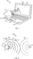
- FIG. 1 shows an illustrative implementation of the various embodiments on a laptop computer 100.
- a user interface system within the laptop computer 100 includes an ultrasound emitter 101 and a plurality of ultrasound detectors 102a, 102b, 102c positioned on various parts of the computer 100.
- a user may position a hand 104 within the 3-D space 106 above or within the vicinity of the computer 100.
- the user may move a hand 104 within a zone where ultrasound reflections may be detected by the ultrasound detectors 102a, 102b, 102c (which is referred to herein as a reflection detection zone) to perform user input gestures that the computing device can recognize and implement.
- Graphical representation of the gestures may be presented on the display 108 similar to other graphical user interface systems.
- the user can interface with the computer 100 without touching any surfaces.
- Embodiments enable a touchless user interface system in which user input gestures may be performed in 3-D space, enabling full 3-D user interface capabilities, unlike conventional graphical user interface devices (e.g., computer mouse, touchpad or touch screen) which are strictly two-dimensional.
- FIG. 2 shows a simple representation of how ultrasound can be used to detect the position and orientation of a user's hand 104.
- An ultrasound emitter 101 may emit continuous wave ultrasound 206 which propagates through the air. By encoding information in the emitted ultrasound, positional information regarding the user's hand 104 can be determined with continuous wave sound. For simplicity of representation, recognizable features within the continuous wave ultrasound are illustrated with concentric arcs.
- the emitted ultrasound 206 will reflect off a user's hand 104 when it is within the reflection detection zone resulting in reflected ultrasound 207, 208. Since the user's hand is three-dimensional, a plurality of reflected ultrasound wave fronts 207, 208 will result from reflections from various features on the user's hand.
- the wave front reflected off of each feature in any given instant will differ. Further, the distance from various features on the user's hand to each ultrasound detector 102 will also differ. Consequently, sound reflected from a user's hand 104 will arrive at a detector 102 in a plurality of wave fronts each slightly offset from one another in time. The reflected ultrasound arriving at a detector 102 thus encodes information regarding the location, shape and orientation of a user's hand. In a conventional imaging ultrasound system, the echo arrival time measured by detectors 102 may be used to generate an image of the reflecting surface.
- Modern ultrasound imaging systems use phased array systems in order to develop accurate images.
- image generation is processor intensive, and thus not suitable for basic user interface systems.
- the various embodiments bypass the imaging process, and instead make use of the location, shape and orientation information that is encoded in received ultrasound by processing changes in the channel impulse response of the communication channel spanning the emitter 101, the reflecting surface 104, and the detector 102, as well as the intervening space.
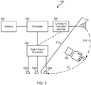
- FIG. 3 illustrates a computing system 300 implementing various embodiments.
- An embodiment computing system 300 may include an ultrasound emitter 101 and one or more ultrasound detectors or microphones 102a, 102b, 102c that are coupled to a digital signal processor 302 that is coupled to the central processor 304 of the computing device.
- the central processor 304 may be coupled to a memory 306 and to an ultrasound modulator/amplifier circuit 308 which is coupled to the ultrasound emitter 101.
- the ultrasound modulator/amplifier circuit 308 may be configured to receive from the processor 304 information to be encoded into continuous wave ultrasound, such as a pseudorandom number or pseudorandom noise. It may use this information to generate the electrical signal applied to the ultrasound emitter 101 to emit the modulated ultrasound.
- the ultrasound modulator/amplifier circuit 308 may be coupled to the digital signal processor 302 and configured to receive the signals of information to be modulated into ultrasound from the digital signal processor 302 instead of from the central processor 304.
- the ultrasound emitter 101 may be a separate sound emitting component, such as an ultrasound transducer mounted on the surface of the computing device.
- the ultrasound emitter 101 may be the computing device's speaker or an element within the speaker, such as a piezo speaker or tweeter element.
- the ultrasound detectors or microphones 102a, 102b, 102c may be separate components, such as dedicated ultrasound transducers.
- ultrasound may be sensed by the computing device's microphone or an element within the microphone, such as a high-frequency sensing component.
- one or more ultrasound transducers may function either as an ultrasound emitter or as an ultrasound detector.
- the various embodiments make use of a communication channel 310 that is defined to encompass the ultrasound emitter 101, the propagation path 312 through the air from ultrasound emitter 101 to the user's hand 104, reflections from the user's finger or hand 104, the propagation path 314 through the air from the user's hand 104 to an ultrasound detector 102a, and the ultrasound detector 102a, 102b, 102c.
- a separate communication channel will thus exist between the ultrasound emitter 101 and each of ultrasound detector 102a, 102b, 102c included in the computing system 300.
- ultrasound detector 102a may be implemented with two or more ultrasound detectors in various locations on the computing system 300 in order to obtain more information regarding the location, shape, and orientation of the user's hand 104 or to better distinguish user input gestures.
- any one of the elements of the through the air ultrasound mitigation channel 310 may result in changes in the channel impulse response.
- properties of the ultrasound emitter 101 and detector 102a, as well as the sound propagation characteristics of the surrounding air may be presumed to be constant within the timeframe of a typical user interface gesture, which will span just a few seconds.
- changes in these elements of the communication channel 312 due to changes in temperature, humidity, etc. may be ignored. Therefore, analysis of the communication channel 310 can be accomplished presuming that all changes in the impulse response are due to changes in the location, shape, and orientation of a reflecting surface, such as a user's hand 104.
- movement of the user's hand 104 towards the ultrasound emitter 101 will reduce the emitter-to-hand propagation path 312 and, most likely, change (lengthen or shorten) the hand-to-detector propagation path 314.
- movement of the user's hand 104 such as rotating, extending or retracting fingers, etc. will change the orientation of reflecting surfaces vis-a-vis the impinging ultrasound, and thus change the pattern of the reflected ultrasound that is received by the detector 102a.
- rapid movement of the user's hand 104 towards or away from the ultrasound emitter 101 may also cause a Doppler shift in the reflected ultrasound that is received by the ultrasound detector 102a.
- the computing system 300 can obtain information regarding the position, shape and orientation of the user's hand 104.
- the computing system 300 can obtain three-dimensional position information regarding the user's hand 104.
- Calculations involved in the sampling of ultrasound signals received by the ultrasound detectors 102a, 102b, 102c, and the determination of the channel impulse response for each communication channel 310 may be performed by the digital signal processor 302 or another suitably configured processing circuit. Processing of the channel impulse response data, such as the filtering, grayscale processing, and statistical analysis of the various embodiments described below may be performed in the digital signal processor 302, or partially in the digital signal processor 302 and partially in the central processor 304. Recognizable features extracted from the channel impulse response by the processing performed in the digital signal processor 302 and/or central processor 304 may be compared to patterns stored in the memory 306 using pattern comparison algorithms performed by the central processor 304 or another processor within the computing system 300.
- the central processor 304 may determine the user input commands associated with the matched pattern and implement the command like any other user input command.
- FIG. 4 illustrates functional modules and hardware elements of an embodiment system 400.
- a pseudorandom noise or pseudorandom number generator module 402 may generate a pseudorandom code. This code may be provided to a spread spectrum modulator and pulse compression module 404 which includes the pseudorandom noise in digital information that is provided to a digital to analog converter and amplifier module 406. This module 406 may provide an analog signal to the ultrasound emitter 101.
- emitted ultrasound 206 reflects off of a user's hand 104 generating reflected ultrasound 208 which is received by one or more ultrasound detectors or microphones 102a, 102b, 102c.
- Signals from the one or more ultrasound detectors or microphones 102a, 102b, 102c may be processed by an amplifier and analog to digital converter module 407 with the resulting digital data passed to a digital signal processor 409.
- the analog to digital conversion process module 407 may be included within the digital signal processor 409.
- the digital signal processor 409 may be configured with DSP-executable software modules including a channel impulse response analysis module 408 and a feature extraction module 410. Processing accomplished in the channel impulse response analysis module 408 and a feature extraction module 410 is described in more detail below.
- Results from the feature extraction module 410 may be processed by a channel impulse response pattern comparison module 412 that compares extracted features to patterns stored in memory 306.
- the channel impulse response pattern comparison module 412 may calculate correlation values reflecting the degree to which a channel impulse response pattern matches or is similar to a pattern stored in memory.
- These results may be processed by a gesture recognition module 414 which functions to select a best matching pattern and identify its associated user input command.
- the gesture recognition module 414 may take into consideration the context of the user input gesture or current operating state to select among matched patterns those which are most relevant to the current operating condition. In doing so, the gesture recognition module 414 may select a pattern with a relatively high correlation factor if its associated user input command is relevant to the current operating state.
- the gesture recognition module 414 may discard those patterns. Also, the gesture recognition module 414 may take into consideration previous input gestures (e.g., a selection command) in selecting among the patterns with relatively high correlation factors, to select among patterns associated with commands relevant to the previous user input command. For example, if the previous input gesture was a selection command, the gesture recognition module 414 may select among patterns associated with a command relevant to a selected object, such as pattern associated with a move, copy, or cut command.
- previous input gestures e.g., a selection command
- the gesture recognition module 414 may select among patterns associated with a command relevant to a selected object, such as pattern associated with a move, copy, or cut command.
- a single command associated with a best matching pattern under the circumstances and consistent with the current operating state identified by the gesture recognition module 414 may be passed to a user interface module 416 for execution like any other user interface command.
- the user interface module 416 may pass the identified command to the processor for execution.
- the user interface module 416 may also generate a display which is provided to the computing device display that is consistent with the identified command.
- the user interface module 416 may generate a graphical user interface display that shows that the object has been selected, such as in a manner similar to how selected objects are shown in graphical user interfaces featuring a computer mouse, touchpad or touchscreen user interface device.
- the gesture recognition module 414 determines that the user has executed a move command (e.g., by moving a hand from one position to another following execution of a select command)
- the user interface module 416 may generate a display showing the selected object moving within the displayed image.
- user input gestures may be determined by or implemented based upon the three-dimensional location of the user's finger or hand.
- the location of a reflector within the reflection detection zone may be determined based upon the time of arrival of reflected ultrasound at the ultrasound detectors. This time of flight will depend upon the distance from the emitter to the user's hand and from the hand to each ultrasound detector.
- the time of flight can be determined based upon the encoded signal since the computing device knows the time or relative time when each encoded signal is broadcast and can detect the arrival of the reflection based upon the information included within the signal.
- the determined time of flight data from each ultrasound detector can then be processed by the coordinate determining module 422 to estimate the location of the reflector using elliptical triangulation methods. Since the received reflected ultrasound is likely to be a noisy channel, Kalman filtering of the data may be used to determine a most likely time of arrival which then can be used in the elliptical triangulation calculations. Embodiment methods for determining the coordinates of a reflector are described more fully below.
- the coordinates of the user's hand determined by the coordinate determining module 420 may be used as inputs to the user interface module 416.
- the coordinates of the tip of a user's finger determined by the coordinate determining module 420 may be used by the user interface module 416 to position a cursor or pointer on a graphical user interface display.
- a user may move a finger about within the reflection detection zone in order to manipulate a cursor or pointer on the display screen in a manner similar to how users manipulate cursors and pointers using a computer mouse, touch pad or touchscreen user input device.
- the coordinates of a user's hand determined by the coordinate determining module 420 may be used by the user interface module 416 to position a selected object shown in a graphical user interface display.
- Some user interface gestures may be recognized by the gesture recognition module 414 based both upon matched patterns in channel impulse response features and upon the coordinates of the user's hand or finger.
- reflection coordinates may also be provided by the coordinate determining module 420 to the gesture recognition module 414.
- the gesture recognition module 414 may then determine a user input gesture based upon pattern match correlation values, context or operating state and location of the user's hand or finger within the reflection detection zone. For example, a given movement of a user's hand may have different meanings (i.e., correlated to different user input commands) depending upon whether the motion is performed close to or far away from the computing device display or keyboard.
- a user waving a hand back and forth at a distance from the display may be associated with a command to wake up the computer or deactivate a screen saver on the display, while a user waving a hand back and forth close to the display may be associated with a command to erase or delete a selected object or portion of the display.
- FIG. 4 is provided as an example of one possible organization of the various embodiment processes and operations, but is not intended to limit the scope of the claims to the illustrated configuration.
- the processing and operations of the various embodiments may be configured in hardware, software, or combinations of hardware and software that may be organized or interact in a manner different from that shown in FIG. 4 .
- One method that may be used to encode temporal information into continuous wave emitted sound is to generate pseudorandom noise and utilize a spectrum modulation scheme. In this manner, at each instant the embedded ultrasound is different from all other instances (depending upon the degree of randomness of the noise) which enables reflected sound arriving from different points of reflection to encode information regarding the position, orientation and shape of a reflected surface over distances longer than the wavelength of the sound.
- pseudorandom noise instead of non-random or systematic encoding (e.g., a continuous sweep through a range of ultrasound frequencies) may render the system less vulnerable to noise and deterministic interference since any condition or interference which results in a degraded channel response in one instance is unlikely to be encountered again until the same random noise and frequency combination is emitted, which will be extremely infrequent when a suitably randomizing method is used.
- Methods for generating pseudorandom noise are well known in the communication arts, and include generating a long pseudorandom number that is encoded into the signal.
- a pseudorandom number is a binary sequence that appears random over a very large number of bits.
- Modulation of the pseudorandom noise into the continuous wave ultrasound may result in an ultrasound signal that spans a broad range of frequencies. This may be accomplished by encoding a pseudorandom number using a spread spectrum modulation method, such as orthogonal frequency division multiplex (OFDM) modulation and pulse compression.
- OFDM orthogonal frequency division multiplex
- the various embodiments analyze information encoded in the reflected ultrasound by determining the channel impulse response and comparing changes in the data over time to patterns of such data stored in memory.
- a channel impulse response refers to the reaction of communication channel in response to some external change.
- the external change is movement of the reflector (i.e., a user's hand or finger) within the reflection detection zone.
- the channel impulse response describes the reaction of the channel as a function of time as the user's hand or finger moves within the reflection detection zone.
- the channel impulse response of a particular emitter-hand-detector ultrasound transmission path channel may be analyzed in a number of well-known manners. For example the output of a channel y(t) may be modeled as the sum of the products of the impulse x(t) applied to the channel (i.e., the emitted ultrasound signal in this instance) and the impulse response h(t) of the channel.
- y(t) x(t) * h(t).
- the channel output may be estimated using equation 1 below.
- y n x n ⁇ h 0 + x n ⁇ 1 ⁇ h 1 + ... x n ⁇ M ⁇ 1 ⁇ h M ⁇ 1
- Eq. 1 can be transformed into matrix format to enable solution by a computer processor (e.g., a DSP).
- a computer processor e.g., a DSP
- an X matrix may be defined as the matrix of x(n), x(n-1), ...x(n-N-M) which is the known transmitted signal pattern.
- H H a * H e .
- a band pass filter in the ultrasound band may be used to pre-process the input signals in order to reject the audio band noise. If so, its impulse response will be part of (i.e., included within) the impulse response H.
- the channel impulse response can be calculated from the signal measured by the ultrasound detectors.
- the calculated impulse response H may then be smoothed by using a smooth factor to reduce noise. While the foregoing shows how the channel impulse response can be calculated from time domain measurements, channel impulse response can also be calculated in the frequency domain.
- the computing device may process the total channel impulse response to delete the portion of the response due to direct transmission in order to reveal the difference that represents the channel impulse response due to the reflected ultrasound.
- the channel impulse response due to the reflected ultrasound may be determined by subtracting an average background channel impulse response (i.e., the channel impulse response measured when there is no reflector present in the reflection detection zone) from the total channel impulse response calculated based upon the measured ultrasound signals.
- the background channel measurement can be measured at predetermined intervals whenever no reflector is presented within the reflection detection zone. Subtracting the average background channel impulse response from the total channel impulse response yields the "reflector channel impulse response.”
- H r H t - H bg (hereinafter "Eq. 2") where H r is the reflector channel impulse response, H t is the total channel impulse response and H bg is the background channel impulse response.
- Channel impulse responses calculated by matrix inversion may be sensitive to noise at the microphones. The reflector channel response may be more robust to noise.
- Changes in the reflector channel impulse response as a function of time may be tracked and used to measure the relative changes of the reflector channel impulse response versus time.
- a “difference channel impulse response” can be calculated as the difference in the reflector channel impulse response at a first sampling time and the reflector channel impulse response in the next sampling time.
- H d (n) H r (n) - H r (n-1) (hereinafter "Eq. 3")
- H d (n) is the difference channel impulse response at time n.
- the difference channel impulse response may be used to recognize dynamic user input gestures in which the user is moving a hand or finger within the reflection detection zone.
- the difference channel impulse responses may be buffered in memory as a series of images over time.
- FIGs. 5A through 5D illustrate an example of the results of processing difference channel impulse response images obtained in a prototype system.
- FIG. 5A shows the raw results of the calculate channel impulse response versus time for a single microphone in the presence of a reflector, such as a user's hand.
- the channel impulse response was measured using 70 signal taps.
- the features in the total measured channel impulse response shown in FIG. 5A are mixed in with the crosstalk channel impulse response, so the background channel impulse response needs to be subtracted before the features in the reflected channel impulse response can be determined.
- FIG. 5B illustrates the measured background channel impulse response obtained with the same system when there is no user hand in reflection detection zone. With no reflector present, the channel impulse response is predictably relatively uniform over time.
- the reflector channel impulse response can be obtained using Eq. 2. Then, by measuring the difference channel impulse response using equation Eq. 3, trends in the reflector channel impulse response may be revealed as shown in FIG. 5C . As FIG. 5C illustrates, the difference channel impulse response contains significant information about movements of the reflector (i.e., the user's hand) within the reflection detection zone.
- FIG. 5D illustrates another view of the difference impulse response as measured in the prototype.
- a grey level covariance matrix may be determined from an edge filtered channel impulse response.
- a grey level covariance matrix is a well known image processing technique, which may involve a tabulation of how often different combinations of grey levels occur in an image matrix at a given offset.
- Grey levels may represent a spectrum of values ranging from a simple on and off to any number of variables. For example, grey levels for an image may range from zero to four with zero being white, four being black, and the numbers in between representing shades of gray.
- an offset parameter may be set. This offset defines how combinations of elements will be grouped for comparisons.
- the offset parameter may be defined so that each image matrix element is compared to the neighboring element to the right.
- a value is added to one of the elements in the grey level covariance matrix.
- Each element of the grey level covariance matrix will contain a value representing the number of times that certain grey levels are combined and compared together.
- the sum of the elements in the grey level covariance matrix equals the number of comparisons, but if grey levels are clustered in the image, certain elements will contain relatively high values. Conversely if the image's grey levels are well mixed and the image is relatively homogenous, the values in the elements will be evenly dispersed.
- Grey level covariance matrices are often applied to images, but they may be used to search for patterns in dispersion of values, or grey levels, within any matrix.
- the buffered difference channel impulse response images may each be used to populate a grey level covariance matrix.
- Statistical features may be derived from each of these grey level covariance matrices.
- the difference channel impulse response images may be processed using edge filters.
- Edge filtering may help to reveal or extract aspects of interest within the images and reduce the overall processing required to obtain useful information from the channel impulse response data.
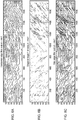
- edge filters By using different types of edge filters, different patterns may be detected in the analyzed channel impulse response based on the changes in the position and movement of the user's hand within the reflection detection zone. Such patterns are illustrated in FIG. 6A through FIG. 7C .
- difference channel impulse response data was obtained while a user moved a finger away from and towards a microphone in the reflector detection zone.
- the difference channel impulse response data was then processed with three types of edge filters.
- the results of applying a horizontal edge filter to the data is shown in FIG. 6A , with the left half of the figure corresponding to when the user's finger was moving away from the microphone and the right half of the figure corresponding to when the user's finger was moving towards the microphone.
- FIG. 6B shows the results of applying a diagonal edge filter to the same data
- FIG. 6C shows the results of applying a maximum horizontal and diagonal edge filter to the same data.
- FIG. 7A through 7C show an example of patterns that may be detected using edge filters applied to the difference channel impulse response when a user's hand moves.
- difference channel impulse response data was obtained while a user moved a hand back and forth within the reflection detection zone.
- the difference channel impulse response data was processed with three types of edge filters.
- a horizontal edge filter yielded the patterns shown in FIG. 7A
- a diagonal edge filter yielded the patterns shown in FIG. 7B
- a maximum horizontal and diagonal edge filter yielded the patterns shown in FIG. 7C .
- a computing device may compare measured patterns to patterns stored in memory in order to identify a closest matching pattern using well known pattern recognition algorithms. The closest matching pattern may then be correlated to a user input gesture stored in the memory of the computing device.
- a horizontal edge filter may be sensitive to a user's hand remaining stationary within the reflection detection zone, such as a finger hovering in place, and may be a preferred edge filter to use to extract recognizable patterns resulting from such positions.
- a diagonal edge filter may be more sensitive to relative movement between the user's hand and the sensors within the reflection detection zone.
- the computing device may try different edge filters to select the type of edge filter that provides the best extraction of features for the particular user gesture, and then continue to use the selected edge filter for processing the difference channel impulse response images in order to extract features to be compared to patterns stored in memory.
- Extracted features may be used to cluster or classify the difference channel impulse response images.
- Statistical processing of the difference channel impulse response image may be used to accomplish this.
- One method that may be implemented is a grey level covariance matrix analysis.
- Frequency and spatial domain features may be extracted from a grey level covariance matrix calculated from the edge filtered responses.
- Spatial features may include a correlation function, second order function, inverse difference matrix function, or a difference entropy function. An example of such an analysis is provided below.
- k
- FIGs. 8A-8D show simulation results of correlations performed for the situation where a user finger moves away from a microphone.
- FIG. 8A illustrates the correlation results from applying Equation 4 at 0 degree.
- FIG. 8B illustrates the correlation results from applying Equation 4 at 90 degrees.
- FIG. 8C illustrates the correlation results from applying Equation 4 at 45 degrees.
- FIG. 8D illustrates the correlation results from applying Equation 4 at 135 degrees.
- FIG. 9A shows simulation results of an angular second order correlation performed for the situation where a user finger moves away from a microphone.
- FIG. 9B shows simulation results of an inverse difference matrix correlation performed for the situation where a user finger moves away from a microphone.
- FIG. 9C shows simulation results of a difference entropy correlation performed for the situation where a user finger moves away from a microphone.
- frequency domain features may also be extracted.
- a power spectrum density may be obtained by applying a two-dimensional fast Fourier transform (FFT) to difference channel impulse response images.
- FFT fast Fourier transform
- the power spectrum density may show more low frequency components when a reflector moves toward a receiver and more high frequency components when a reflector moves away from a receiver, and thus may provide further information that may be used to recognize or categorize user input gestures.
- ring and wedge sampling of the FFT results may be used to identify impulse response wave directions. Ring and wedge sampling may be done over a series of radially aligned semi-annular regions and wedge regions extending from the center of the reflection detection zone. Sampling of semi-circular ring areas may provide orientation-independent information about the distribution of spatial frequencies in the difference channel impulse response image, while sampling of angular wedge areas may provide scale-independent information.
- Classifications of difference channel impulse response images may be used to identify the strongest reflection points for use in making time of flight calculations that can be used to determine a location of the strongest reflection point in 3-D space.
- the time of flight may be calculated for identified reflection points.
- the transmitter and number of receivers may be synchronized to the same system clock and thereby eliminate the need for timestamping of the ultrasound transmissions.
- the time of flight measurements for each receiver may simply be the difference of the transmission time of a signal and the reception time for a matched signal.
- Time of flight values may be used to determine the coordinates of the reflection points in three dimension space. Coordinates may be in a frame of reference with origin at the transmitter, the receiver or some other location. The coordinates of the receivers relative to the origin may be previously known or determined. The coordinates of a reflection point may be determined by converting the time of flight values of three or more receivers into distances based on an ultrasound speed and using the distances in an elliptical intersect method. The speed of sound may assumed as a constant, a , as channel conditions are not likely to fluctuate drastically in the short period between each measurement, but the constant may need to be adjusted over time in changing channel conditions.
- x, y, z are the reflection coordinates
- mx1, my1, mz1 are the coordinates of micl
- 0, 0, 0 are the speaker coordinates.
- the time of flight values to be used for determining reflection coordinates may be noisy.
- a Kalman filter may be used to overcome noisiness and determine the reflection coordinates.
- an extended (EKF) or "unscented Kalman filter” may be used.
- Kalman filters predict the true value of measurements and calculated estimates by weighting and combining predicted values and measured values.
- a Kalman filter may predict a value and estimate the uncertainty of the predicted value.
- a Kalman filter process may assign a weighting to the predicted value based upon uncertainty, with higher weights going to more certain values, and then compute a weighted average with measured values. In this manner, noisy measured values may be adjusted to be closer to the true value because the weighted average has a better estimated uncertainty than either the predicted value or the measured value.
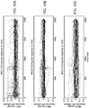
- FIGs. 10A-10C show results of Kalman filtering of data generated in a simulation of a user finger hovering about 1 cm above the surface of a computer device with three microphones.
- FIG. 10A shows simulation channel impulse response versus time results for the first microphone.
- FIG. 10B shows simulation channel impulse response versus time results for the second microphone.
- FIG. 10C shows simulation channel impulse response versus time results for the third microphone. Since the microphones are positioned at different locations on the computing device, they exhibit different channel impulse responses.
- FIG. 11A shows the maximum amplitude of the channel impulse response versus time determined from the processing illustrated in FIGs. 10A-10C for all three microphones.
- FIG. 11B shows the index value of the channel impulse response versus time determined from the processing illustrated in FIGs. 10A-10C for all three microphones.
- FIG. 11C shows the amplitude of the measurement value at the maximum index versus time determined from the processing illustrated in FIGs. 10A-10C for all three microphones.
- training data sets can be used to train the classifier.
- the classifier may be a simple KNN classifier or more complex ANN or HMM model.
- Features extracted by the foregoing analysis methods may be correlated with specific user input gestures, such as may be defined in a user training sequence.
- Well known pattern comparison or correlation methods may be used to compare patterns extracted from the channel impulse response to patterns stored in memory.
- Three examples of correlation methods that may be used for this purpose are k-nearest neighbors algorithms, artificial neural networks analysis, and hidden Markov Models.
- the artificial neural networks or hidden Markov models may have been previously trained in a learning phase. These three example correlation methods are described in more detail below; however, other correlation methods may also be used in a similar manner.
- the k-nearest neighbor algorithm classifies an object by a majority vote of a number, k, of the nearest neighbors. Neighbors are taken from a set of already correctly classified objects, in this case patterns extracted from difference channel impulse response images. Rules are set defining which classified objects, or neighbors, are closest. For example, certain features or changes in coordinates may be neighbors and classified or correlated with certain gestures ahead of time. Patterns extracted from difference channel impulse response images to be classified may have features extracted with values close to certain neighbors. Depending on the parameter k selected, a number of neighbors may be compared. If k equals five, the five neighboring patterns with the closest feature values may determine what the patterns extracted from difference channel impulse response images is classified as.
- the patterns extracted from difference channel impulse response images may be correlated with the same gesture as the majority. Using such a comparison algorithm, it is possible to weight the votes of neighbors by closeness or any other one or more properties.
- Artificial neural networks is a comparison method that uses calculation of objects that function as interconnected group of artificial neurons that may change structure based on information flowing in the network during a learning phase. Connections in the neural network may vary in strength or weighting. Each artificial neuron may be a simple processing node or function, but the network as a whole may exhibit complex behaviors.
- An artificial neural network may learn by using a set of observations to find optimal solutions to a task where optimal is measured according to a predefined cost function. For example during a learning phase, a user may be asked to perform a particular user input gesture a number of times so that a number of observations can be obtained. The observations or patterns extracted from difference channel impulse response images may be fed into the neural network and run through the various nodes and connections to generate solutions.
- the solutions generated by the neural network may be ranked according to a cost function. Weighting of connections may be adjusted based on this ranking. Once properly trained, the neural network's weighting values may be fixed.
- a neural network may be used for pattern recognition or classification of gestures by comparing patterns extracted from difference channel impulse response images to learn the patterns from the training session. Solutions may be analogous to certain user input gestures. Features or changes in coordinates may serve as the input for a previously trained neural network that would then connect the input with a solution or gesture based on the neural network structure. The neural network may be previously trained with known gestures or features in a learning phase.
- a hidden Markov model assumes that the system being modeled is a Markov process with an unknown state but with known tokens dependent on the state.
- a Markov process is a process in which a state fluctuates over time and in which future states depend only upon the present state and no previous states.
- Each possible state has a probability distribution over the possible tokens and probability distribution as to which state will come next. Therefore, the tokens give some information about the sequence of states in the process.
- the states may be analogous features associated with user input gestures and the tokens may be analogous with the patterns extracted from difference channel impulse response images.
- the probability distributions over tokens and between states may be predefined parameters or may be set in a learning phase.
- Patterns extracted from difference channel impulse response images of known gestures or features can be input to train and develop parameter values of the model in a learning phase.
- the most likely sequence of states or gestures may be determined recursively from the trained Hidden Markov model, such as by the Viterbi algorithm.
- simple gesture recognition tasks such as identifying a reflector's moving directions, may be accomplished using angle features derived directly from the impulse response curve.
- FIGs. 12A through 16C illustrate how the impulse response patterns for different reflector movements and their corresponding response curve angle information may be recognized.
- FIGs. 12A through 12C Graphs of the impulse response determinations for each of three microphones in a prototype in the presence of a finger moving towards the microphones are illustrated in FIGs. 12A through 12C . These figures show the raw impulse response determinations after processing with a diagonal edge filter. As can be seen in these figures, the motion of a user's finger toward the microphone may result in a perceivable angle in the impulse response determinations as a function of time, as indicated in the sample frame index.
- FIGs. 13A through 13C Graphs of the impulse response determinations for each of three microphones in a prototype in the presence of a finger moving towards the microphones after processing with a loop low pass filter are illustrated in FIGs. 13A through 13C . As these figures reveal that applying the low pass filter to the impulse response provides a more distinct pattern which can be used to determine the angle of the impulse response.
- this angle can be used as a recognizable feature that can be linked to a particular movement.
- an angle less than 90 degree may mean a reflector (e.g., a user's hand or finger) is moving closer to the microphone, while an angle between 90 and 180 degree may mean that a reflector is moving away from the microphone.
- Such a user movement may then be correlated to a particular user interface command (e.g., a mouse pointer movement) using a simple table look up method.
- FIG. 14 illustrates an embodiment method 450 which may be implemented in a computing device to recognize user input gestures from ultrasound reflected from a user's hand within a reflection detection zone based on determining the angle of the impulse response.
- a processor may generate a pseudorandom noise or pseudorandom number code, or other temporal encoding information, and encode that information in a spread spectrum modulation with pulse compression in step 454. This encoded signal is then emitted as a continuous wave ultrasound from an ultrasound emitter in step 456. Ultrasound, including reflected and cross talk signals, is received at an ultrasound detector in step 458.
- a processor e.g., a DSP
- the processor may subtract a baseline channel impulse response to obtain a reflected channel impulse response using the methods described above.
- the computing device processor may calculate the difference channel impulse response over time, and maintain a series of those values as difference channel impulse response images using calculation methods described above. Also as part of step 462, the computing device processor may apply an edge filter, low pass filter and thresholding operations to the calculated difference impulse response.
- the processor may select a rectangular filter with various filtering angles.
- the processor may select a region of the channel impulse response that contains a certain number of samples frames that can cover the entire rectangle filter.
- the processor may move the filter within the region while summing the points within the filter in order to calculate the maximum value of the summation of all the points within the filter.
- the processor may repeat steps 466 and 468 for each angle of the selected rectangular filter. Once all of the angles of the filter have been processed, in step 472, the processor may determine the angle of the impulse response curve for each frame after the regions are selected across the whole impulse response matrix.
- the processor implement the user input command corresponding to the determine angle of the impulse response curve.
- the computing device may display a user interface image corresponding to the implemented user input command in a manner similar to other user interface systems.
- the angle of the impulse response curve may be plotted over time as illustrated in FIGs. 15A-15C .
- FIGs. 15A-15C These figures illustrate the change in the detected angle of the impulse pattern in degrees as a function of the sample frame index for the case where the user's finger is moving towards the three microphones of the system.
- the derived angle of the impulse response curve from all three microphones can uniquely determine the reflector moving directions in 3D space. As illustrated in FIGs. 15A-15C , the change in angle over time will differ for each of the three microphones when they are positioned in different locations on or in the vicinity of the computing device. Two microphones may be used to determine the direction of reflector movement when it is moving parallel to a line connecting the two microphones.
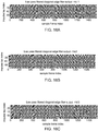
- FIGs. 16A through 17C graph the impulse response determinations for each of three microphones in a prototype in the presence of a finger moving towards and then away from the microphones after processing with a loop low pass filter. These figures reveal how the angle of the impulse response curve changes from a first value to a second value and then back again as the user's finger moves towards, then away, and then towards the microphones.
- FIGs. 17A - 17C graph the angle of the impulse response curves for the impulse response curves shown in FIGs. 16A - 16C for each of the three microphones in the system.
- the embodiment analysis methods enable gesture recognition while avoiding the need to demodulate the received ultrasound because imaging the reflector is not necessary for gesture recognition.
- the ultrasound does not serve as a carrier of information from the transmitter, but rather as a collector of information about the reflector (i.e., the user's hand) with the information extracted in the form of the channel impulse response as affected by any reflecting surfaces within the reflection detection zone.
- the embodiment methods avoid the data intensive process of resolving or forming an image of a reflecting surface, such as the user's hand. Instead, gesture recognition is accomplished by relying on changes in the channel impulse response without having to map the reflected data or determining what the channel is.
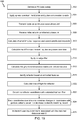
- FIG. 18 illustrates an embodiment method 500 which may be implemented in a computing device to recognize user input gestures from ultrasound reflected from a user's hand within a reflection detection zone.
- a processor may generate a pseudorandom noise or pseudorandom number code, or other temporal encoding information, and encode that information in a spread spectrum modulation with pulse compression in step 504.
- This encoded signal is then emitted as a continuous wave ultrasound from an ultrasound emitter in step 506.
- Ultrasound, including reflected and cross talk signals is received at an ultrasound detector in step 508.
- a processor e.g., a DSP
- the processor may subtract a baseline channel impulse response to obtain a reflected channel impulse response using the methods described above.
- the computing device processor may calculate the difference channel impulse response over time, and maintain a series of those values as difference channel impulse response images using calculation methods described above.
- the processor may apply an edge filter to the difference channel impulse response images to highlight recognizable features.
- the processor may calculate a grey level covariance matrix in order to extract recognizable features from the edge filtered difference channel impulse response images.
- the processor may compare the extracted features from the edge filtered difference channel impulse response images to patterns as stored in a database associated with user gestures in order to identify a matching record.
- step 518 may involve comparing patterns for gestures that are relevant to our current operating state or application in the computing device, or other state related considerations.
- the processing in step 518 may use correlation methods such as k-nearest neighbors, artificial neural nets, and hidden Markov models.
- the results of step 518 may be an identified user input command associated with the matched gesture pattern.
- the computing device may implement the identified user command associated with the matched pattern.
- the computing device may display a user interface image corresponding to the recognize gesture in a manner similar to other user interface systems.
- the processes illustrated in FIG. 18 may also be used in a training sequence, with the exception that the user may be prompted to perform a particular gesture, and instead of comparing the extracted features in step 518, the processor may store the extracted features in a database.
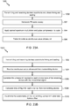
- FIG. 19 illustrates an alternate embodiment method 600 in which the feature extraction and correlation steps of method 500 may be used to identify a reflecting object and recognize motion of the object.
- a temporally encode ultrasound signal may be generated and emitted in steps 502-506.
- the ultrasound signal and reflections from a user's hand may be received and processed to obtain a difference channel impulse response images in steps 508-512.
- the difference channel impulse response images may be edge filtered and analyzed with a grey level covariance matrix to extract recognizable features in steps 514-516.
- the extracted features may be used to identify reflection points of interest for time of flight calculations in step 618.
- the selection of points of interest based on extracted features may rely on the same correlation methods used in step 516. These methods may be used to correlate the extracted features indicating strong primary or secondary reflectors. With a proper grouping of the strong reflections, primary reflectors may be distinguished and identified as the main reflectors.
- time of flight values may be determined by calculating the difference in time from transmission and reception of signals reflected from identified main reflection points.
- coordinates of the identified reflection points may be calculated with the same methods and equations discussed above including Kalman filtering to overcome noisiness in time of flight values.
- step 624 coordinates of identified reflection points may be tracked over time, with changes in coordinates calculated and (optionally) correlated with user input gestures in step 624.
- step 626 the computing device implements the identified user command associated with the matched pattern.
- the computing device may display a user interface image corresponding to the recognize gesture, including its location within 3-D space as determined in steps 620-622, in a manner similar to other user interface systems.
- the processes illustrated in FIG. 19 may also be used in a training sequence, with the exception that the user may be prompted to perform a particular gesture, and instead of comparing the extracted features in step 624, the processor may store the extracted features in a database.
- FIG. 20 An example computing system in the form of a laptop computer 700 suitable for use with the various embodiments, including example positions for the ultrasound emitter 101 and microphones 102a, 102b, and 102c, is illustrated in FIG. 20 .
- Many laptop computers include a touch pad touch surface that serves as the computer's pointing device.
- a laptop computer 700 will typically include a processor 701 coupled to volatile memory 702 and a large capacity nonvolatile memory, such as a disk drive 703.
- the computer 700 may also include a floppy disc drive 704 and a compact disc (CD) drive 705 coupled to the processor 701.
- CD compact disc
- the computer device 700 may also include a number of connector ports coupled to the processor 701 for establishing data connections or receiving external memory devices, such as a USB or FireWire® connector sockets or other network connection circuits 706 for coupling the processor 701 to a network.
- the computer housing includes the touchpad 707, keyboard 708 and the display 709 all coupled to the processor 701.
- An ultrasound transmitter 101 and receivers/microphones 102a-102c may be integrated with the laptop computer 700 in locations on the system housing selected to facilitate 3-D coordinate calculations based on time of flight differences.
- the ultrasound transmitter 101 and receivers/microphones 102a-102c may also serve as a computing device speaker and microphones for other audio functions.
- the gestures determined by an embodiment system or method may serve as input for the computer 700 and be used to control programs thereon or to interact with a graphical user interface.
- the ultrasound touchless sensing capability may augment or replace the touchpad 707 or keyboard 708.
- Mobile devices such as cell phones or PDAs, may also be configured to use the various embodiments.
- Typical mobile devices 800 suitable for use with the various embodiments may include the components illustrated in FIG. 21 .
- an exemplary mobile receiver device 800 may include a processor 801 coupled to internal memory 802, a display 803, and a speaker 809. Additionally, the mobile device 800 may have an antenna 804 for sending and receiving electromagnetic radiation that is connected to a wireless data link and/or cellular telephone transceiver 805 coupled to the processor 801 and/or a mobile multimedia broadcast receiver 808 coupled to the processor 801.
- Mobile devices typically also include a key pad 806 or miniature keyboard and menu selection buttons or rocker switches 807 for receiving user inputs.
- the mobile device 800 may be augmented with embodiments for a touchless user interface.
- the mobile device 800 may use the speaker 804 to emit ultrasound or may incorporate a separate ultrasound emitter, such as an ultrasound transmitter 101.
- the mobile device may receive the ultrasound, such as from reflections or other mobile devices, through one or more receivers/microphones 102a-102c.
- the processor 701, 801 may be any programmable microprocessor, microcomputer or multiple processor chip or chips that can be configured by software instructions (applications) to perform a variety of functions, including the functions of the various embodiments described herein.
- multiple processors 701, 801 may be provided, such as one processor dedicated to wireless communication functions and one processor dedicated to running other applications, such as a separate processor 304.
- software applications may be stored in the internal memory 702, 802 before they are accessed and loaded into the processor 801.
- the processor 701, 801 may include internal memory sufficient to store the application software instructions.
- a general reference to memory refers to all memory accessible by the processor 701, 801, including internal memory 702, 703, 704, 802, removable memory plugged into the device, and memory within the processor 701, 801 itself.
- FIG. 22 Further embodiments may involve multiple devices configured with ultrasound emitting and receiving elements working together.
- two mobile devices 800a, 800b may interact via continuous wave ultrasound.
- the devices 800a, 800b may be positioned near each other in space.
- Each device may include its own emitters 101 and receivers 102, but the devices 800a, 800b may be configured so that one device 800a operates in a transmit mode in which the device's emitter 101 is active and emits continuous wave ultrasound 206, while the other device 800b is in a receive mode receiving the continuous wave ultrasound 206 via the device's receivers 102a, 102b, and 102c.
- the receiving mode device 800b can determine the distance and direction to the emitting device 800a.
- Embodiments further include methods for determining relative coordinates to or distances from the emitter device 800a to the receiver device 800b.
- An embodiment method 1000 that may be implemented on a mobile device 800a operating in a transmit mode is illustrated in FIG. 23A .
- the two devices may communicate to coordinate roles and share information on timing and coding in step 1002. This communication may occur over a wireless communication link, such as Bluetooth, WiFi, or any other form of wireless data connection.
- the devices may coordinate to determine which device will be the transmitting device (i.e., the device that will transmit ultrasound) and which device will be the receiving device (i.e., will receive and process the ultrasound), thereby preventing interference between the devices.
- the devices may also share data regarding the timing of ultrasound transmission frames that the transmitting device will begin transmitting, as well as and data about the code to be transmitted. Once this coordination has occurred, the transmitting device may generate a pseudorandom noise code sweep, step 502, apply spread spectrum modulation and pulse compression, step 504, and transmit the code as continuous wave ultrasound, step 506, similar to the previously discussed embodiments.
- FIG. 23B An embodiment method 1020 that may be implemented on a mobile device 800b operating in a receive mode is illustrated in FIG. 23B .
- the devices may coordinate transmission/reception roles, and timing and encoding formats in step 1002 as discussed above.
- the receiving device may then receive continuous wave ultrasound traveling through the air from the transmitting device in step 1004. To receive the ultrasound transmission, the receiving may need to be within a certain range.
- the receiving device may correlate the ultrasound signals received at each receiver with the transmitted signal as may be reproduced by the receiver device processor based on timing and code information exchanged in step 1002. The information regarding the timing and code information is necessary because unlike previous embodiments, the receivers 102 and the emitter 101 are not part of the same device tied to the same clock.
- the receiving device may calculate the time of flight for the transmitted signal to reach each receiver in step 1008, and the time of flight values may be used with a Kalman filter to determine the coordinates in step 1010.
- the time of flight calculations and Kalman filtering process may be performed in a manner similar to that discussed above with respect to other embodiments, except that the receiving device is determining relative coordinates of the transmitting device instead of a reflecting surface.
- ⁇ ML arg max t ⁇ ⁇ ⁇ ⁇ ⁇ ML f X 1 f X 2 * f e j 2 ⁇ ft df and X 1 ( f ), X 2 ( f ) are the frequency domain signals from the two microphones, and ⁇ ML ( f ) is the weighting factor.
- GCC generalized cross correlation
- coordinates, direction, or distances may be used for many different tasks. For example, a user could select the correct device intended for file sharing based on its relative coordinates or direction with respect to a sending device. A different connection would be used for the file transfer, but the coordinates or directions determined from processing the ultrasound signals could be used to select a destination or source of the file, rather than relying on an address or special name which the user may not know. For example, if the user is in a room with several people using such devices, the user could differentiate between the different devices just by looking around.
- the user could send a file to a friend standing to the left by selecting via a device graphical user interface a device with the coordinates or directions that match up with the intended recipient, thereby avoiding accidentally sending the file to a stranger.
- a user may want to transfer a song from an audio player to a stereo. If the stereo is in a room full of other appliances with similar touchless interfaces, the user could rely on relative coordinates or direction determined from such ultrasound tracking systems to pick the stereo rather than the microwave or the dishwasher.
- FIGs. 22A and 22B illustrate just one of the ways in which two of more devices may interact using the various embodiments.
- the devices may be used in a manner similar to that discussed in the previous embodiments, with a device taking the place of a user's hand.
- a receiving device may track movement of the transmitting device or extract features or patterns of the transmitting device's movement that may be correlated with various commands or other communications.
- DSP digital signal processor
- ASIC application specific integrated circuit
- FPGA field programmable gate array
- a general-purpose processor may be a microprocessor, but, in the alternative, the processor may be any conventional processor, controller, microcontroller, or state machine.
- a processor may also be implemented as a combination of computing devices, e.g., a combination of a DSP and a microprocessor, a plurality of microprocessors, one or more microprocessors in conjunction with a DSP core, or any other such configuration. Alternatively, some steps or methods may be performed by circuitry that is specific to a given function.
- the functions described may be implemented in hardware, software, firmware, or any combination thereof. If implemented in software, the functions may be stored on or transmitted over as one or more instructions or code on a computer-readable medium.
- the steps of a method or algorithm disclosed herein may be embodied in a processor-executable software module executed which may reside on a tangible non-transitory computer-readable medium or processor-readable medium.
- Non-transitory computer-readable and processor-readable media may be any available media that may be accessed by a computer or processor.
- non-transitory computer-readable media may comprise RAM, ROM, EEPROM, CD-ROM or other optical disk storage, magnetic disk storage or other magnetic storage devices, or any other medium that may be used to carry or store desired program code in the form of instructions or data structures and that may be accessed by a computer.
- Disk and disc includes compact disc (CD), laser disc, optical disc, digital versatile disc (DVD), floppy disk, and blu-ray disc where disks usually reproduce data magnetically, while discs reproduce data optically with lasers. Combinations of the above should also be included within the scope of computer-readable media.
- the operations of a method or algorithm may reside as one or any combination or set of codes and/or instructions on a non-transitory processor-readable medium and/or computer-readable medium, which may be incorporated into a computer program product.
Description
- This application claims the benefit of priority to
U.S. Provisional Patent Application No. 61/359,728 - The present invention relates generally to user interface systems for computing devices, and more particularly to a touchless user interface employing continuous-wave sound.
- Ultrasound is a cyclic sound pressure defined as operating at frequencies above the upper limits of human hearing or above approximately 20 kHz. Ultrasound has been implemented a wide range of applications for imaging, source location determination and range measurements. Many of these applications focus on ultrasound's ability to penetrate a medium and provide structural information of objects within the medium via reflections. Most applications make use of ultrasound by measuring the time delay between when ultrasound is emitted and when echoes are detected. In general terms, the two types of ultrasound systems are pulse echo and continuous wave.
- Prior art document
WO 2009/122193 A1 describes multi-range object location estimation. In particular, it discloses a method for recognizing a user input gesture, comprising: receiving with a sound detector ultrasound signals, thereby forming a communication channel; calculating a channel impulse response for said communication channel based on the received signals; processing each channel impulse response to extract a plurality of features; identifying a matching stored gesture; and executing a command associated with the matched stored gesture. Further, a time-shift function is applied to an initial signal to produce a transmit signal for transmission by a transmitter. A receiver receives a received signal, and an inverse time shift function is applied to the received signal. By applying the time-shift function to the output signal and by applying the inverse time shift function to the received signal, echoes of interest form a continuous line, relating to a "physically plausible motion", whereas the echoes that are not of interest appear as scattered noise. - Further ultrasound-based systems for human-machine interaction are disclosed in
WO 2009/115799 A1 , andWO 2004/102301 A2 . - Embodiments provide systems and methods for touchless sensing and gesture recognition suitable for use as a user interface using continuous wave ultrasound signals.
- The features defining the invention are specified in the independent claims. Preferred realisations are specified in the dependent claims. The present description may refer to various aspects and embodiments, however, it should be clear that only those embodiments that fall within the scope of the claims also form part of the invention.
- The accompanying drawings, which are incorporated herein and constitute part of this specification, illustrate exemplary embodiments of the invention, and together with the general description given above and the detailed description given below, serve to explain the features of the invention.
-
FIG. 1 is an illustration of an embodiment system configured to use ultrasound sensors for gesture recognition. -
FIG. 2 is a concept diagram of illustrating ultrasound wave fronts propagating from an emitter or speaker, reflecting off a hand of a user and being received by the detectors. -
FIG. 3 is a functional and component block diagram of an embodiment system for recognizing gestures with continuous wave ultrasound. -
FIG. 4 is a functional system block diagram of the various processing and hardware modules of an embodiment system. -
FIG. 5A is a graph of a channel impulse response versus time for a microphone in a prototype system in the presence of a reflector (e.g., a user's hand). -
FIG. 5B is a graph of a channel impulse response versus time for a microphone in a prototype system with no reflector present. -
FIG. 5C is a graph of the channel impulse response versus time of a reflector alone computed as the difference between the channel impulse response illustrated inFIG. 5A and the channel impulse response illustrated inFIG. 5B in a prototype system. -
FIG. 5D is also a graph of the difference impulse response. -
FIGs. 6A-6C are graphs showing results of applying different forms of the edge filtering to differential channel response versus time in which a user's finger moves towards and away from a microphone in a prototype system. -
FIGs. 7A-7C are graphs showing results of applying different forms of the edge filtering to differential channel response versus time in which a user's hand moves left to right and right to left two times in front of a microphone in a prototype system. -
FIGs. 8A-8D are graphs showing results of statistical correlation analysis of the simulation results for a user finger moving away from a microphone using four different correlation functions. -
FIGs. 9A-9C with are graphs showing results of statistical correlation analysis of the simulation results for a user finger moving away from a microphone using three different correlation algorithms. -
FIGs. 10A-10C are graphs illustrating channel impulse responses versus time for a user gesture as measured by three spaced apart microphones in a prototype system. -
FIG. 11A is a graph illustrating maximum impulse responses values versus time determine from the channel impulse responses versus time illustrated inFIGs. 10A-10C . -
FIG. 11B is a graph illustrating maximum impulse responses indexes versus time determine from the channel impulse responses versus time illustrated inFIGs. 10A-10C . -
FIG. 11C is a graph illustrating the measured value of the impulse responses versus time at the maximum index determine from the channel impulse responses versus time illustrated inFIGs. 10A-10C . -
FIGs. 12A-12C are graphs of raw impulse responses determinations versus time for three microphones in the presence of a moving reflector. -
FIGs. 13A-13C are graphs of low-pass filtered and thresholded impulse responses determinations versus time for three microphones in the presence of a moving reflector. -
FIG. 14 is a process flow diagram of an embodiment method for recognizing a user interface gesture from reflected ultrasound signals based on a determined angle of the impulse response. -
FIGs. 15A-15C are graphs of detected angles of the impulse responses patterns shown inFIGs. 13A-13C , respectively. -
FIGs. 16A-16C are graphs of low-pass filtered impulse responses determinations versus time for three microphones in the presence of a reflector moving towards and away from the microphones. -
FIGs. 17A-17C are graphs of detected angles of the impulse responses patterns shown inFIGs. 16A-16C , respectively. -
FIG. 18 is a process flow diagram of an embodiment method for recognizing gestures based on signal features extracted from a channel impulse response. -
FIG. 19 is a process flow diagram of an embodiment method for recognizing gestures based on signal features extracted and a change in coordinates of a reflector. -
FIG. 20 is a component block diagram of an example computer suitable for use with the various aspects. -
FIG. 21 is a component block diagram of an example mobile device suitable for use with the various aspects. -
FIG. 22 is an embodiment system of two mobile devices interacting with continuous wave ultrasound. -
FIG. 23A is a process flow diagram of an embodiment method for determining directions between devices on the transmitting device. -
FIG. 23B is a process flow diagram of an embodiment method for determining directions between devices on the receiving device. - The various embodiments will be described in detail with reference to the accompanying drawings. Wherever possible, the same reference numbers will be used throughout the drawings to refer to the same or like parts. References made to particular examples and implementations are for illustrative purposes, and are not intended to limit the scope of the invention or the claims.
- The word "exemplary" is used herein to mean "serving as an example, instance, or illustration." Any implementation described herein as "exemplary" is not necessarily to be construed as preferred or advantageous over other implementations.
- As used herein, the term "computing device" refers to any form of programmable computer device with a user interface, including but not limited to laptop and desktop computers, televisions, home appliances, cellular telephones, personal television devices, personal data assistants (PDA's), palm-top computers, wireless electronic mail receivers (e.g., the Blackberry® and Treo® devices), multimedia Internet enabled cellular telephones (e.g., the Blackberry Storm®), Global Positioning System (GPS) receivers, wireless gaming controllers, receivers within vehicles (e.g., automobiles), interactive game devices, notebooks, smartbooks, netbooks, mobile television devices, or any data processing apparatus.
- The various embodiments provide systems and methods for touchless user interface sensing and gesture recognition by computing devices using continuous wave ultrasound signals that are emitted from the device and received by one or more detectors or microphones. Continuous wave ultrasound may be emitted by a transmitter or speaker, reflected from an object (e.g., a user's hand), and received by one or more receivers or microphones. For example, an ultrasound emitter or speaker may transmit appropriately encoded continuous wave ultrasound. The ultrasound may propagate through the air and reflect off of a user's hand if the hand is positioned within a reflection detection zone. The reflected ultrasound may be received by one, two, three, or more ultrasound detectors or microphones positioned about the computing device. In the various embodiments, a "channel" may include the sound path from the ultrasound emitter through the air to the user's hand, the reflections from the user's hand through the air to each detector, and the response of each detector. Characteristics of such a channel may be expressed in a channel impulse response which can be determined using known signal processing methods and circuits (e.g., a digital signal processor). Thus, as a user moves a hand or object within a reflection detection zone of the computing device, the characteristics of the channel and the channel impulse response will change due to the different transmission paths of reflected ultrasound. This may include changes in the pattern of reflected echoes due to changes in the angles of incidence of the hand surfaces with respect to the emitted ultrasound. Such changes in the channel impulse response over time can be analyzed to reveal patterns that can be compared to known patterns stored in memory in order to recognize intended user input gestures. Also, any large reflections or portions of a user's hand generating recognized channel impulse response patterns may be processed to measure the time of flight of the ultrasound, from which the computing device can determine the location of the reflecting surface within the 3-D space surrounding the computing device using well known elliptical triangulation calculations. Accurate methods for determining distances to reflecting surface may use well known processing algorithms, such as Kalman filtering, in order to account for noise in the system.
- In addition to providing three-dimensional user input gesture recognition capability, touchless gesture sensing capabilities of the various embodiments provide other advantages. The system can detect and interpret user gestures within a large volume surrounding the computing device, such as within 30-40 centimeters around the computing device. Additionally, since the user interface space is above the computing device, the user interface can be configured to be resistant to external conditions, e.g., moisture, dirt, etc. Thus, the various embodiments may have applications in circumstances, systems and locations in which a conventional computer is unsuitable.
- In overview, continuous wave ultrasound signal may be modulated in a manner that enables received reflected signals to be correlated with the emitted signal. Matching signals may allow the system to determine the channel impulse response or calculate the difference in time between transmission and reception, or time of flight. System channel input response snapshots or images may be buffered over time to enable changes in the response to be recognized and compared to patterns stored from training sessions. Such buffered images of the channel impulse response may be filtered using special filtering to extract features that can be matched to pre-trained template library of user input gestures. In addition to processing impulse response, particular echo features, such as may be associated with a strongest echo or a first arriving echo, may be processed in order to obtain an accurate estimation of the location of the echo source in 3-D space using time of flight analysis. Mathematical processing, such as Kalman filtering, may be used in order to accurately determine the time of flight or distance in the presence of noise, which is likely to be the case in most use situations. In order to analyze and match the received reflections, embodiments may comprise various signal processing elements. These signal processing elements may filter out patterns and features from the received channel response and correlate these features to a gesture without ever resolving the reflecting object in the channel.
- By comparing detected patterns in the channel impulse response to patterns stored in memory, such as from user training sessions, the computing device can identify a most closely matching pattern. By correlating particular user input commands to particular trained gesture patterns, the computing device can be configured to recognize particular user hand movements as user input commands. Thus, in some embodiments, the ultrasound detection system may be implemented as part of a graphical user interface portion of the operating system. In such embodiments, when a channel impulse response pattern is matched to a pattern in memory, an associated user command may be identified and implemented by the computing device. In this manner, a user may control a computing device by pointing or moving a hand above or within the vicinity of a computing device similar to how user commands can be input using known pointing devices or touchscreen displays.
- While the various embodiments are described as sending and receiving ultrasound, the embodiments may also be implemented with sound with frequencies below the typical ultrasound region. Provided that the emitted frequencies are above the audible range, the various embodiments may be implemented with high-frequency sound in the manner described herein. Ultrasound is advantageous due to its small wavelength which enables resolution of fine structures of a user's hand. However, due to the low density of air, lower frequency sound may be easier and more efficient to generate using conventional speakers and easier to receive in conventional microphones. Therefore, references to ultrasound herein are not intended to limit the scope of the claims to sound within particular frequency ranges except as specifically recited.
-
FIG. 1 shows an illustrative implementation of the various embodiments on alaptop computer 100. In the illustrated embodiment, a user interface system within thelaptop computer 100 includes anultrasound emitter 101 and a plurality ofultrasound detectors computer 100. In use, a user may position ahand 104 within the 3-D space 106 above or within the vicinity of thecomputer 100. Rather than using a conventional pointing device, such as a touchpad 110, the user may move ahand 104 within a zone where ultrasound reflections may be detected by theultrasound detectors display 108 similar to other graphical user interface systems. Thus, by moving ahand 104 within the X, Y and Z axes of a coordinatesystem 106 above or around thecomputer 100, the user can interface with thecomputer 100 without touching any surfaces. Embodiments enable a touchless user interface system in which user input gestures may be performed in 3-D space, enabling full 3-D user interface capabilities, unlike conventional graphical user interface devices (e.g., computer mouse, touchpad or touch screen) which are strictly two-dimensional. -
FIG. 2 shows a simple representation of how ultrasound can be used to detect the position and orientation of a user'shand 104. Anultrasound emitter 101 may emitcontinuous wave ultrasound 206 which propagates through the air. By encoding information in the emitted ultrasound, positional information regarding the user'shand 104 can be determined with continuous wave sound. For simplicity of representation, recognizable features within the continuous wave ultrasound are illustrated with concentric arcs. The emittedultrasound 206 will reflect off a user'shand 104 when it is within the reflection detection zone resulting in reflectedultrasound ultrasound wave fronts ultrasound emitter 101, the wave front reflected off of each feature in any given instant will differ. Further, the distance from various features on the user's hand to eachultrasound detector 102 will also differ. Consequently, sound reflected from a user'shand 104 will arrive at adetector 102 in a plurality of wave fronts each slightly offset from one another in time. The reflected ultrasound arriving at adetector 102 thus encodes information regarding the location, shape and orientation of a user's hand. In a conventional imaging ultrasound system, the echo arrival time measured bydetectors 102 may be used to generate an image of the reflecting surface. - Modern ultrasound imaging systems use phased array systems in order to develop accurate images. However, such image generation is processor intensive, and thus not suitable for basic user interface systems. The various embodiments bypass the imaging process, and instead make use of the location, shape and orientation information that is encoded in received ultrasound by processing changes in the channel impulse response of the communication channel spanning the
emitter 101, the reflectingsurface 104, and thedetector 102, as well as the intervening space. -
FIG. 3 illustrates acomputing system 300 implementing various embodiments. Anembodiment computing system 300 may include anultrasound emitter 101 and one or more ultrasound detectors ormicrophones digital signal processor 302 that is coupled to thecentral processor 304 of the computing device. Thecentral processor 304 may be coupled to amemory 306 and to an ultrasound modulator/amplifier circuit 308 which is coupled to theultrasound emitter 101. The ultrasound modulator/amplifier circuit 308 may be configured to receive from theprocessor 304 information to be encoded into continuous wave ultrasound, such as a pseudorandom number or pseudorandom noise. It may use this information to generate the electrical signal applied to theultrasound emitter 101 to emit the modulated ultrasound. In some implementations, the ultrasound modulator/amplifier circuit 308 may be coupled to thedigital signal processor 302 and configured to receive the signals of information to be modulated into ultrasound from thedigital signal processor 302 instead of from thecentral processor 304. - In some embodiments, the
ultrasound emitter 101 may be a separate sound emitting component, such as an ultrasound transducer mounted on the surface of the computing device. In other embodiments, theultrasound emitter 101 may be the computing device's speaker or an element within the speaker, such as a piezo speaker or tweeter element. Similarly, in some embodiments, the ultrasound detectors ormicrophones - As described above, the various embodiments make use of a
communication channel 310 that is defined to encompass theultrasound emitter 101, thepropagation path 312 through the air fromultrasound emitter 101 to the user'shand 104, reflections from the user's finger orhand 104, thepropagation path 314 through the air from the user'shand 104 to anultrasound detector 102a, and theultrasound detector ultrasound emitter 101 and each ofultrasound detector computing system 300. Although the various embodiments may be implemented with asingle ultrasound detector 102a, two or more ultrasound detectors may be positioned in various locations on thecomputing system 300 in order to obtain more information regarding the location, shape, and orientation of the user'shand 104 or to better distinguish user input gestures. - Like any communication channel, changes in any one of the elements of the through the air
ultrasound mitigation channel 310 may result in changes in the channel impulse response. In most operating conditions, properties of theultrasound emitter 101 anddetector 102a, as well as the sound propagation characteristics of the surrounding air, may be presumed to be constant within the timeframe of a typical user interface gesture, which will span just a few seconds. Thus, changes in these elements of thecommunication channel 312 due to changes in temperature, humidity, etc. may be ignored. Therefore, analysis of thecommunication channel 310 can be accomplished presuming that all changes in the impulse response are due to changes in the location, shape, and orientation of a reflecting surface, such as a user'shand 104. For example, movement of the user'shand 104 towards theultrasound emitter 101 will reduce the emitter-to-hand propagation path 312 and, most likely, change (lengthen or shorten) the hand-to-detector propagation path 314. Also, movement of the user'shand 104, such as rotating, extending or retracting fingers, etc. will change the orientation of reflecting surfaces vis-a-vis the impinging ultrasound, and thus change the pattern of the reflected ultrasound that is received by thedetector 102a. Additionally, rapid movement of the user'shand 104 towards or away from theultrasound emitter 101 may also cause a Doppler shift in the reflected ultrasound that is received by theultrasound detector 102a. Such changes in thecommunication channel 310 resulting from the user'shand 104 movements within the reflection detection zone will be reflected in the channel's impulse response. Thus, by analyzing changes in thecommunication channel 310 impulse response over time, thecomputing system 300 can obtain information regarding the position, shape and orientation of the user'shand 104. By placing three ormore ultrasound detectors computing system 300, such as spaced apart in three dimensions such as illustrated inFIG. 20 described below, thecomputing system 300 can obtain three-dimensional position information regarding the user'shand 104. - Calculations involved in the sampling of ultrasound signals received by the
ultrasound detectors communication channel 310 may be performed by thedigital signal processor 302 or another suitably configured processing circuit. Processing of the channel impulse response data, such as the filtering, grayscale processing, and statistical analysis of the various embodiments described below may be performed in thedigital signal processor 302, or partially in thedigital signal processor 302 and partially in thecentral processor 304. Recognizable features extracted from the channel impulse response by the processing performed in thedigital signal processor 302 and/orcentral processor 304 may be compared to patterns stored in thememory 306 using pattern comparison algorithms performed by thecentral processor 304 or another processor within thecomputing system 300. If thecentral processor 304 determines that patterns extracted from the channel impulse responses of one or more of thecommunication channels 310 match a pattern stored in thememory 306, thecentral processor 304 may determine the user input commands associated with the matched pattern and implement the command like any other user input command. -
FIG. 4 illustrates functional modules and hardware elements of anembodiment system 400. To generate the emitted continuous wave ultrasound, a pseudorandom noise or pseudorandomnumber generator module 402 may generate a pseudorandom code. This code may be provided to a spread spectrum modulator andpulse compression module 404 which includes the pseudorandom noise in digital information that is provided to a digital to analog converter andamplifier module 406. Thismodule 406 may provide an analog signal to theultrasound emitter 101. As described above, emittedultrasound 206 reflects off of a user'shand 104 generating reflectedultrasound 208 which is received by one or more ultrasound detectors ormicrophones microphones digital converter module 407 with the resulting digital data passed to adigital signal processor 409. In some implementations, the analog to digitalconversion process module 407 may be included within thedigital signal processor 409. Thedigital signal processor 409 may be configured with DSP-executable software modules including a channel impulseresponse analysis module 408 and afeature extraction module 410. Processing accomplished in the channel impulseresponse analysis module 408 and afeature extraction module 410 is described in more detail below. - Results from the
feature extraction module 410 may be processed by a channel impulse responsepattern comparison module 412 that compares extracted features to patterns stored inmemory 306. The channel impulse responsepattern comparison module 412 may calculate correlation values reflecting the degree to which a channel impulse response pattern matches or is similar to a pattern stored in memory. These results may be processed by agesture recognition module 414 which functions to select a best matching pattern and identify its associated user input command. Thegesture recognition module 414 may take into consideration the context of the user input gesture or current operating state to select among matched patterns those which are most relevant to the current operating condition. In doing so, thegesture recognition module 414 may select a pattern with a relatively high correlation factor if its associated user input command is relevant to the current operating state. For example, if multiple patterns have relatively high correlation factors, but some of the patterns have associated user input commands that cannot be executed in the current operating state (e.g., commands related to applications that are not currently executing), thegesture recognition module 414 may discard those patterns. Also, thegesture recognition module 414 may take into consideration previous input gestures (e.g., a selection command) in selecting among the patterns with relatively high correlation factors, to select among patterns associated with commands relevant to the previous user input command. For example, if the previous input gesture was a selection command, thegesture recognition module 414 may select among patterns associated with a command relevant to a selected object, such as pattern associated with a move, copy, or cut command. - A single command associated with a best matching pattern under the circumstances and consistent with the current operating state identified by the
gesture recognition module 414 may be passed to auser interface module 416 for execution like any other user interface command. Theuser interface module 416 may pass the identified command to the processor for execution. Theuser interface module 416 may also generate a display which is provided to the computing device display that is consistent with the identified command. For example, if thegesture recognition module 414 determines that the user has executed a select command (e.g., by pointing to an object in 3-D space, pinching two fingers together, or forming a fist) theuser interface module 416 may generate a graphical user interface display that shows that the object has been selected, such as in a manner similar to how selected objects are shown in graphical user interfaces featuring a computer mouse, touchpad or touchscreen user interface device. As another example, if thegesture recognition module 414 determines that the user has executed a move command (e.g., by moving a hand from one position to another following execution of a select command), theuser interface module 416 may generate a display showing the selected object moving within the displayed image. - In a further embodiment, user input gestures may be determined by or implemented based upon the three-dimensional location of the user's finger or hand. In such embodiments, it is necessary for the computing device to determine an absolute or relative location of the user's finger or hand within the reflection detection zone. This may be accomplished by a time of
flight calculation module 418 and a coordinate determiningmodule 420. The location of a reflector within the reflection detection zone may be determined based upon the time of arrival of reflected ultrasound at the ultrasound detectors. This time of flight will depend upon the distance from the emitter to the user's hand and from the hand to each ultrasound detector. The time of flight can be determined based upon the encoded signal since the computing device knows the time or relative time when each encoded signal is broadcast and can detect the arrival of the reflection based upon the information included within the signal. The determined time of flight data from each ultrasound detector can then be processed by the coordinate determining module 422 to estimate the location of the reflector using elliptical triangulation methods. Since the received reflected ultrasound is likely to be a noisy channel, Kalman filtering of the data may be used to determine a most likely time of arrival which then can be used in the elliptical triangulation calculations. Embodiment methods for determining the coordinates of a reflector are described more fully below. - The coordinates of the user's hand determined by the coordinate determining
module 420 may be used as inputs to theuser interface module 416. For example, the coordinates of the tip of a user's finger determined by the coordinate determiningmodule 420 may be used by theuser interface module 416 to position a cursor or pointer on a graphical user interface display. In this manner, a user may move a finger about within the reflection detection zone in order to manipulate a cursor or pointer on the display screen in a manner similar to how users manipulate cursors and pointers using a computer mouse, touch pad or touchscreen user input device. As a further example, the coordinates of a user's hand determined by the coordinate determiningmodule 420 may be used by theuser interface module 416 to position a selected object shown in a graphical user interface display. - Some user interface gestures may be recognized by the
gesture recognition module 414 based both upon matched patterns in channel impulse response features and upon the coordinates of the user's hand or finger. Thus, reflection coordinates may also be provided by the coordinate determiningmodule 420 to thegesture recognition module 414. Thegesture recognition module 414 may then determine a user input gesture based upon pattern match correlation values, context or operating state and location of the user's hand or finger within the reflection detection zone. For example, a given movement of a user's hand may have different meanings (i.e., correlated to different user input commands) depending upon whether the motion is performed close to or far away from the computing device display or keyboard. Thus, a user waving a hand back and forth at a distance from the display may be associated with a command to wake up the computer or deactivate a screen saver on the display, while a user waving a hand back and forth close to the display may be associated with a command to erase or delete a selected object or portion of the display. -
FIG. 4 is provided as an example of one possible organization of the various embodiment processes and operations, but is not intended to limit the scope of the claims to the illustrated configuration. The processing and operations of the various embodiments may be configured in hardware, software, or combinations of hardware and software that may be organized or interact in a manner different from that shown inFIG. 4 . - One method that may be used to encode temporal information into continuous wave emitted sound is to generate pseudorandom noise and utilize a spectrum modulation scheme. In this manner, at each instant the embedded ultrasound is different from all other instances (depending upon the degree of randomness of the noise) which enables reflected sound arriving from different points of reflection to encode information regarding the position, orientation and shape of a reflected surface over distances longer than the wavelength of the sound. The use of pseudorandom noise instead of non-random or systematic encoding (e.g., a continuous sweep through a range of ultrasound frequencies) may render the system less vulnerable to noise and deterministic interference since any condition or interference which results in a degraded channel response in one instance is unlikely to be encountered again until the same random noise and frequency combination is emitted, which will be extremely infrequent when a suitably randomizing method is used. Methods for generating pseudorandom noise are well known in the communication arts, and include generating a long pseudorandom number that is encoded into the signal. A pseudorandom number is a binary sequence that appears random over a very large number of bits. Modulation of the pseudorandom noise into the continuous wave ultrasound may result in an ultrasound signal that spans a broad range of frequencies. This may be accomplished by encoding a pseudorandom number using a spread spectrum modulation method, such as orthogonal frequency division multiplex (OFDM) modulation and pulse compression.
- With temporal information included within the continuous wave ultrasound, information related to the location and surface features of reflector is (e.g., a user's hand) can be extracted from the received reflected ultrasound. However, as noted above, imaging of a reflector would require a lot of processing power but is not necessary to accomplish user input gesture recognition. Instead, the various embodiments analyze information encoded in the reflected ultrasound by determining the channel impulse response and comparing changes in the data over time to patterns of such data stored in memory.
- A channel impulse response refers to the reaction of communication channel in response to some external change. In the various embodiments the external change is movement of the reflector (i.e., a user's hand or finger) within the reflection detection zone. The channel impulse response describes the reaction of the channel as a function of time as the user's hand or finger moves within the reflection detection zone. The channel impulse response of a particular emitter-hand-detector ultrasound transmission path channel may be analyzed in a number of well-known manners. For example the output of a channel y(t) may be modeled as the sum of the products of the impulse x(t) applied to the channel (i.e., the emitted ultrasound signal in this instance) and the impulse response h(t) of the channel. In other words, y(t)= x(t)* h(t). The channel output may be estimated using
equation 1 below.
- To solve this equation using signal tap measurements over a sampling period, Eq. 1 can be transformed into matrix format to enable solution by a computer processor (e.g., a DSP). If the known transmitted signal pattern at time n is defined as x(n), an X matrix may be defined as the matrix of x(n), x(n-1), ...x(n-N-M) which is the known transmitted signal pattern. Matrix Y representing the received signal is defined as Y = [y(n) y(n-1) ... y(n-N-1)]' where y(n) is given by Eq. 1. Matrix H, which is the channel impulse responses to be calculated then can be defined as H=[h(0), h(1), ... h(M-1)] '. The channel output may then be defined by Y = X * H, where Y is an N by 1 matrix, H is an M by 1 matrix, and X is an N by M matrix. Therefore, the channel impulse response H may be determined by H = X-1 * Y. In real systems, H is the convolution result of both acoustic and electronic channels. H = Ha * He. X * H = X * Ha * He = Y+N, where N is noise, Ha is the acoustic path, and He is the electrical path. Given an electrical channel, the acoustic path can be obtained as: Ha = (X * He)-1 * Y.
- In an embodiment, a band pass filter in the ultrasound band may be used to pre-process the input signals in order to reject the audio band noise. If so, its impulse response will be part of (i.e., included within) the impulse response H.
- Since the emitted ultrasound signal pattern X(n) is known, many pseudo matrix inversion methods, such as generalized singular value decomposition, can be used to calculate the inverse of matrix X. Due to the presence of noise in the received microphone signals, proper regularization measures may be needed to derive a stable solution. Using that result, the channel impulse response can be calculated from the signal measured by the ultrasound detectors. The calculated impulse response H may then be smoothed by using a smooth factor to reduce noise. While the foregoing shows how the channel impulse response can be calculated from time domain measurements, channel impulse response can also be calculated in the frequency domain.
- The impulse response update rate may be determined by the size of matrix X and length of H which are a matter of memory that is allocated to the processing associated with the ultrasound gesture recognition processes. For example, if N + M = 800, the received ultrasound signal may be sampled and the channel impulse response may be updated 240 times per second (i.e., 240 Hz).
- As illustrated in
FIG. 4 , there are two sets of ultrasound signals arriving at thedetectors 102, the reflected set ofsignals 208 which are the desired aspects and the direct transmission of the emittedsound 206. The direct sound transmission may be referred to as crosstalk. The computing device may process the total channel impulse response to delete the portion of the response due to direct transmission in order to reveal the difference that represents the channel impulse response due to the reflected ultrasound. The channel impulse response due to the reflected ultrasound may be determined by subtracting an average background channel impulse response (i.e., the channel impulse response measured when there is no reflector present in the reflection detection zone) from the total channel impulse response calculated based upon the measured ultrasound signals. Since ultrasound is not audible to the human ear, the background channel measurement can be measured at predetermined intervals whenever no reflector is presented within the reflection detection zone. Subtracting the average background channel impulse response from the total channel impulse response yields the "reflector channel impulse response." Thus, Hr = Ht - Hbg (hereinafter "Eq. 2") where Hr is the reflector channel impulse response, Ht is the total channel impulse response and Hbg is the background channel impulse response. Channel impulse responses calculated by matrix inversion may be sensitive to noise at the microphones. The reflector channel response may be more robust to noise. - Changes in the reflector channel impulse response as a function of time may be tracked and used to measure the relative changes of the reflector channel impulse response versus time. A "difference channel impulse response" can be calculated as the difference in the reflector channel impulse response at a first sampling time and the reflector channel impulse response in the next sampling time. In other words: Hd(n) = Hr(n) - Hr(n-1) (hereinafter "Eq. 3") where Hd(n) is the difference channel impulse response at time n. The difference channel impulse response may be used to recognize dynamic user input gestures in which the user is moving a hand or finger within the reflection detection zone. To facilitate analysis, the difference channel impulse responses may be buffered in memory as a series of images over time.
-
FIGs. 5A through 5D illustrate an example of the results of processing difference channel impulse response images obtained in a prototype system.FIG. 5A shows the raw results of the calculate channel impulse response versus time for a single microphone in the presence of a reflector, such as a user's hand. In this prototype, the channel impulse response was measured using 70 signal taps. The features in the total measured channel impulse response shown inFIG. 5A are mixed in with the crosstalk channel impulse response, so the background channel impulse response needs to be subtracted before the features in the reflected channel impulse response can be determined.FIG. 5B illustrates the measured background channel impulse response obtained with the same system when there is no user hand in reflection detection zone. With no reflector present, the channel impulse response is predictably relatively uniform over time. By subtracting the background channel impulse response shown inFIG. 5B from the measured total channel impulse response shown inFIG. 5A , the reflector channel impulse response can be obtained using Eq. 2. Then, by measuring the difference channel impulse response using equation Eq. 3, trends in the reflector channel impulse response may be revealed as shown inFIG. 5C . AsFIG. 5C illustrates, the difference channel impulse response contains significant information about movements of the reflector (i.e., the user's hand) within the reflection detection zone.FIG. 5D illustrates another view of the difference impulse response as measured in the prototype. - One of the methods for distinguishing recognizable features in channel impulse response data involves applying a grey level covariance matrix analysis to the data. A grey level covariance matrix may be determined from an edge filtered channel impulse response. A grey level covariance matrix is a well known image processing technique, which may involve a tabulation of how often different combinations of grey levels occur in an image matrix at a given offset. Grey levels may represent a spectrum of values ranging from a simple on and off to any number of variables. For example, grey levels for an image may range from zero to four with zero being white, four being black, and the numbers in between representing shades of gray. To form the grey level covariance matrix, an offset parameter may be set. This offset defines how combinations of elements will be grouped for comparisons. For example, the offset parameter may be defined so that each image matrix element is compared to the neighboring element to the right. Depending on the grey levels of the two elements of each combination, a value is added to one of the elements in the grey level covariance matrix. Each element of the grey level covariance matrix will contain a value representing the number of times that certain grey levels are combined and compared together. The sum of the elements in the grey level covariance matrix equals the number of comparisons, but if grey levels are clustered in the image, certain elements will contain relatively high values. Conversely if the image's grey levels are well mixed and the image is relatively homogenous, the values in the elements will be evenly dispersed.
- Grey level covariance matrices are often applied to images, but they may be used to search for patterns in dispersion of values, or grey levels, within any matrix. The buffered difference channel impulse response images may each be used to populate a grey level covariance matrix. Statistical features may be derived from each of these grey level covariance matrices. By applying grey scale processing on the difference channel impulse response, further detail in the patterns contained within the signal can be obtained.
- In order to reveal or extract features within the difference channel impulse responses, the difference channel impulse response images may be processed using edge filters. Edge filtering may help to reveal or extract aspects of interest within the images and reduce the overall processing required to obtain useful information from the channel impulse response data. A number of edge filtering processes may be used. For example, a southeast and northwest edge filter may be used as shown below:

- By using different types of edge filters, different patterns may be detected in the analyzed channel impulse response based on the changes in the position and movement of the user's hand within the reflection detection zone. Such patterns are illustrated in
FIG. 6A through FIG. 7C . - Referring to
FIGs. 6A-6C , using a prototype system, difference channel impulse response data was obtained while a user moved a finger away from and towards a microphone in the reflector detection zone. The difference channel impulse response data was then processed with three types of edge filters. The results of applying a horizontal edge filter to the data is shown inFIG. 6A , with the left half of the figure corresponding to when the user's finger was moving away from the microphone and the right half of the figure corresponding to when the user's finger was moving towards the microphone.FIG. 6B shows the results of applying a diagonal edge filter to the same data, andFIG. 6C shows the results of applying a maximum horizontal and diagonal edge filter to the same data. -
FIG. 7A through 7C show an example of patterns that may be detected using edge filters applied to the difference channel impulse response when a user's hand moves. Using the prototype system, difference channel impulse response data was obtained while a user moved a hand back and forth within the reflection detection zone. The difference channel impulse response data was processed with three types of edge filters. A horizontal edge filter yielded the patterns shown inFIG. 7A , a diagonal edge filter yielded the patterns shown inFIG. 7B , and a maximum horizontal and diagonal edge filter yielded the patterns shown inFIG. 7C . - Although the full nature of the patterns in the process channel impulse response data may be difficult to distinguish with the human eye, some clearly recognizable patterns can be appreciated from the figures. Such patterns may be processed or recognized in a manner similar to how two-dimensional bar codes are read by barcode readers systems. By processing the results of the edge filtered difference channel impulse responses over time, a computing device may compare measured patterns to patterns stored in memory in order to identify a closest matching pattern using well known pattern recognition algorithms. The closest matching pattern may then be correlated to a user input gesture stored in the memory of the computing device.
- While a variety of different filters may be applied, an embodiment may only apply one type of filter in a given analysis. For example, a horizontal edge filter may be sensitive to a user's hand remaining stationary within the reflection detection zone, such as a finger hovering in place, and may be a preferred edge filter to use to extract recognizable patterns resulting from such positions. In contrast, a diagonal edge filter may be more sensitive to relative movement between the user's hand and the sensors within the reflection detection zone. Thus, the computing device may try different edge filters to select the type of edge filter that provides the best extraction of features for the particular user gesture, and then continue to use the selected edge filter for processing the difference channel impulse response images in order to extract features to be compared to patterns stored in memory.
- Extracted features may be used to cluster or classify the difference channel impulse response images. Statistical processing of the difference channel impulse response image may be used to accomplish this. One method that may be implemented is a grey level covariance matrix analysis. Frequency and spatial domain features may be extracted from a grey level covariance matrix calculated from the edge filtered responses. Spatial features may include a correlation function, second order function, inverse difference matrix function, or a difference entropy function. An example of such an analysis is provided below.
- If g is defined as the grey level, i may be defined as the series i = 1, 2 ... g, and j may be defined as j = 1, 2 ... g. Further, px may be defined as


- If ux = mean(px ) and uy = mean(py ), and if σx = var(px ) and σ y = var(py ), and g is the grey level, the correlation function may be defined as

- The second order function may be defined as

- The inverse difference matrix function may be defined as

- Px-y(k) and k may be defined as

- The difference entropy function may be defined as

-
FIGs. 8A-8D show simulation results of correlations performed for the situation where a user finger moves away from a microphone.FIG. 8A illustrates the correlation results from applyingEquation 4 at 0 degree.FIG. 8B illustrates the correlation results from applyingEquation 4 at 90 degrees.FIG. 8C illustrates the correlation results from applyingEquation 4 at 45 degrees.FIG. 8D illustrates the correlation results from applyingEquation 4 at 135 degrees. The degree indicates the direction of gradient change of filter coefficients as follows:


-
FIG. 9A shows simulation results of an angular second order correlation performed for the situation where a user finger moves away from a microphone. -
FIG. 9B shows simulation results of an inverse difference matrix correlation performed for the situation where a user finger moves away from a microphone. -
FIG. 9C shows simulation results of a difference entropy correlation performed for the situation where a user finger moves away from a microphone. - In a further embodiment, frequency domain features may also be extracted. In this embodiment, a power spectrum density may be obtained by applying a two-dimensional fast Fourier transform (FFT) to difference channel impulse response images. The power spectrum density may show more low frequency components when a reflector moves toward a receiver and more high frequency components when a reflector moves away from a receiver, and thus may provide further information that may be used to recognize or categorize user input gestures.
- In a further embodiment, ring and wedge sampling of the FFT results may be used to identify impulse response wave directions. Ring and wedge sampling may be done over a series of radially aligned semi-annular regions and wedge regions extending from the center of the reflection detection zone. Sampling of semi-circular ring areas may provide orientation-independent information about the distribution of spatial frequencies in the difference channel impulse response image, while sampling of angular wedge areas may provide scale-independent information.
- Classifications of difference channel impulse response images may be used to identify the strongest reflection points for use in making time of flight calculations that can be used to determine a location of the strongest reflection point in 3-D space. The time of flight may be calculated for identified reflection points. The transmitter and number of receivers may be synchronized to the same system clock and thereby eliminate the need for timestamping of the ultrasound transmissions. Thus, the time of flight measurements for each receiver may simply be the difference of the transmission time of a signal and the reception time for a matched signal.
- Time of flight values may be used to determine the coordinates of the reflection points in three dimension space. Coordinates may be in a frame of reference with origin at the transmitter, the receiver or some other location. The coordinates of the receivers relative to the origin may be previously known or determined. The coordinates of a reflection point may be determined by converting the time of flight values of three or more receivers into distances based on an ultrasound speed and using the distances in an elliptical intersect method. The speed of sound may assumed as a constant, a, as channel conditions are not likely to fluctuate drastically in the short period between each measurement, but the constant may need to be adjusted over time in changing channel conditions. The following equations may be used where x, y, z are the reflection coordinates, mx1, my1, mz1 are the coordinates of micl, and 0, 0, 0 are the speaker coordinates.


- The time of flight values to be used for determining reflection coordinates may be noisy. To address this, a Kalman filter may be used to overcome noisiness and determine the reflection coordinates. For nonlinear systems, an extended (EKF) or "unscented Kalman filter" may be used. Kalman filters predict the true value of measurements and calculated estimates by weighting and combining predicted values and measured values. A Kalman filter may predict a value and estimate the uncertainty of the predicted value. A Kalman filter process may assign a weighting to the predicted value based upon uncertainty, with higher weights going to more certain values, and then compute a weighted average with measured values. In this manner, noisy measured values may be adjusted to be closer to the true value because the weighted average has a better estimated uncertainty than either the predicted value or the measured value.
-
FIGs. 10A-10C show results of Kalman filtering of data generated in a simulation of a user finger hovering about 1 cm above the surface of a computer device with three microphones.FIG. 10A shows simulation channel impulse response versus time results for the first microphone.FIG. 10B shows simulation channel impulse response versus time results for the second microphone.FIG. 10C shows simulation channel impulse response versus time results for the third microphone. Since the microphones are positioned at different locations on the computing device, they exhibit different channel impulse responses. - Using the Kalman filtered results, the maximum channel impulse response value, index and the distance to the maximum signal may be determined.
FIG. 11A shows the maximum amplitude of the channel impulse response versus time determined from the processing illustrated inFIGs. 10A-10C for all three microphones.FIG. 11B shows the index value of the channel impulse response versus time determined from the processing illustrated inFIGs. 10A-10C for all three microphones.FIG. 11C shows the amplitude of the measurement value at the maximum index versus time determined from the processing illustrated inFIGs. 10A-10C for all three microphones. - Once the gesture features are defined, training data sets (gesture features) can be used to train the classifier. The classifier may be a simple KNN classifier or more complex ANN or HMM model. Features extracted by the foregoing analysis methods may be correlated with specific user input gestures, such as may be defined in a user training sequence. Well known pattern comparison or correlation methods may be used to compare patterns extracted from the channel impulse response to patterns stored in memory. Three examples of correlation methods that may be used for this purpose are k-nearest neighbors algorithms, artificial neural networks analysis, and hidden Markov Models. The artificial neural networks or hidden Markov models may have been previously trained in a learning phase. These three example correlation methods are described in more detail below; however, other correlation methods may also be used in a similar manner.
- The k-nearest neighbor algorithm classifies an object by a majority vote of a number, k, of the nearest neighbors. Neighbors are taken from a set of already correctly classified objects, in this case patterns extracted from difference channel impulse response images. Rules are set defining which classified objects, or neighbors, are closest. For example, certain features or changes in coordinates may be neighbors and classified or correlated with certain gestures ahead of time. Patterns extracted from difference channel impulse response images to be classified may have features extracted with values close to certain neighbors. Depending on the parameter k selected, a number of neighbors may be compared. If k equals five, the five neighboring patterns with the closest feature values may determine what the patterns extracted from difference channel impulse response images is classified as. If a majority of five neighbors are correlated with a certain gesture, the patterns extracted from difference channel impulse response images may be correlated with the same gesture as the majority. Using such a comparison algorithm, it is possible to weight the votes of neighbors by closeness or any other one or more properties.
- Artificial neural networks is a comparison method that uses calculation of objects that function as interconnected group of artificial neurons that may change structure based on information flowing in the network during a learning phase. Connections in the neural network may vary in strength or weighting. Each artificial neuron may be a simple processing node or function, but the network as a whole may exhibit complex behaviors. An artificial neural network may learn by using a set of observations to find optimal solutions to a task where optimal is measured according to a predefined cost function. For example during a learning phase, a user may be asked to perform a particular user input gesture a number of times so that a number of observations can be obtained. The observations or patterns extracted from difference channel impulse response images may be fed into the neural network and run through the various nodes and connections to generate solutions. The solutions generated by the neural network may be ranked according to a cost function. Weighting of connections may be adjusted based on this ranking. Once properly trained, the neural network's weighting values may be fixed. A neural network may be used for pattern recognition or classification of gestures by comparing patterns extracted from difference channel impulse response images to learn the patterns from the training session. Solutions may be analogous to certain user input gestures. Features or changes in coordinates may serve as the input for a previously trained neural network that would then connect the input with a solution or gesture based on the neural network structure. The neural network may be previously trained with known gestures or features in a learning phase.
- A hidden Markov model assumes that the system being modeled is a Markov process with an unknown state but with known tokens dependent on the state. A Markov process is a process in which a state fluctuates over time and in which future states depend only upon the present state and no previous states. Each possible state has a probability distribution over the possible tokens and probability distribution as to which state will come next. Therefore, the tokens give some information about the sequence of states in the process. In gesture recognition, the states may be analogous features associated with user input gestures and the tokens may be analogous with the patterns extracted from difference channel impulse response images. The probability distributions over tokens and between states may be predefined parameters or may be set in a learning phase. Patterns extracted from difference channel impulse response images of known gestures or features can be input to train and develop parameter values of the model in a learning phase. The most likely sequence of states or gestures may be determined recursively from the trained Hidden Markov model, such as by the Viterbi algorithm.
- In a further embodiment, simple gesture recognition tasks, such as identifying a reflector's moving directions, may be accomplished using angle features derived directly from the impulse response curve.
FIGs. 12A through 16C illustrate how the impulse response patterns for different reflector movements and their corresponding response curve angle information may be recognized. - Graphs of the impulse response determinations for each of three microphones in a prototype in the presence of a finger moving towards the microphones are illustrated in
FIGs. 12A through 12C . These figures show the raw impulse response determinations after processing with a diagonal edge filter. As can be seen in these figures, the motion of a user's finger toward the microphone may result in a perceivable angle in the impulse response determinations as a function of time, as indicated in the sample frame index. - While the raw impulse response determination is made with real recognizable features, such features may be enhanced by processing the signals using a low pass filter on the block channel impulse response. An example of a low pass filter in the form of a 5X5 matrix of values one is:

- Graphs of the impulse response determinations for each of three microphones in a prototype in the presence of a finger moving towards the microphones after processing with a loop low pass filter are illustrated in
FIGs. 13A through 13C . As these figures reveal that applying the low pass filter to the impulse response provides a more distinct pattern which can be used to determine the angle of the impulse response. - Since the angle of the pattern in the impulse response can be easily determined, this angle can be used as a recognizable feature that can be linked to a particular movement. For example, an angle less than 90 degree may mean a reflector (e.g., a user's hand or finger) is moving closer to the microphone, while an angle between 90 and 180 degree may mean that a reflector is moving away from the microphone. Such a user movement may then be correlated to a particular user interface command (e.g., a mouse pointer movement) using a simple table look up method.
-
FIG. 14 illustrates anembodiment method 450 which may be implemented in a computing device to recognize user input gestures from ultrasound reflected from a user's hand within a reflection detection zone based on determining the angle of the impulse response. Inmethod 450 instep 452, a processor may generate a pseudorandom noise or pseudorandom number code, or other temporal encoding information, and encode that information in a spread spectrum modulation with pulse compression instep 454. This encoded signal is then emitted as a continuous wave ultrasound from an ultrasound emitter instep 456. Ultrasound, including reflected and cross talk signals, is received at an ultrasound detector instep 458. Instep 460, a processor (e.g., a DSP) may calculate a channel impulse response based on the received ultrasound signal. As part ofstep 460, the processor may subtract a baseline channel impulse response to obtain a reflected channel impulse response using the methods described above. Instep 462, the computing device processor may calculate the difference channel impulse response over time, and maintain a series of those values as difference channel impulse response images using calculation methods described above. Also as part ofstep 462, the computing device processor may apply an edge filter, low pass filter and thresholding operations to the calculated difference impulse response. Instep 464, the processor may select a rectangular filter with various filtering angles. Instep 466, the processor may select a region of the channel impulse response that contains a certain number of samples frames that can cover the entire rectangle filter. Instep 468, the processor may move the filter within the region while summing the points within the filter in order to calculate the maximum value of the summation of all the points within the filter. Instep 470, the processor may repeatsteps step 472, the processor may determine the angle of the impulse response curve for each frame after the regions are selected across the whole impulse response matrix. Instep 474, the processor implement the user input command corresponding to the determine angle of the impulse response curve. As part ofstep 474, the computing device may display a user interface image corresponding to the implemented user input command in a manner similar to other user interface systems. - Determining that the angle of the impulse response curve in
step 472 may utilize the following equation:
FIGs. 13A-13C , and (t0, tmax, M) is the size of the rectangular filter. The angle may then be determined as the maximum argument of Recti. In other words: Angle = argmax(Recti), where i=1:N. N is the number of equally divided angles, and the increment step of each angle is π/N. - As part of the process of recognizing a user input gesture using these methods, the angle of the impulse response curve may be plotted over time as illustrated in
FIGs. 15A-15C . These figures illustrate the change in the detected angle of the impulse pattern in degrees as a function of the sample frame index for the case where the user's finger is moving towards the three microphones of the system. - The derived angle of the impulse response curve from all three microphones can uniquely determine the reflector moving directions in 3D space. As illustrated in
FIGs. 15A-15C , the change in angle over time will differ for each of the three microphones when they are positioned in different locations on or in the vicinity of the computing device. Two microphones may be used to determine the direction of reflector movement when it is moving parallel to a line connecting the two microphones. - This method may be used for recognizing more complex user input gestures, such as a user's finger moving towards and away from the system microphones, as illustrated in
FIGs. 16A through 17C . For example,FIGs. 16A - 16C graph the impulse response determinations for each of three microphones in a prototype in the presence of a finger moving towards and then away from the microphones after processing with a loop low pass filter. These figures reveal how the angle of the impulse response curve changes from a first value to a second value and then back again as the user's finger moves towards, then away, and then towards the microphones.FIGs. 17A - 17C graph the angle of the impulse response curves for the impulse response curves shown inFIGs. 16A - 16C for each of the three microphones in the system. - The embodiment analysis methods enable gesture recognition while avoiding the need to demodulate the received ultrasound because imaging the reflector is not necessary for gesture recognition. The ultrasound does not serve as a carrier of information from the transmitter, but rather as a collector of information about the reflector (i.e., the user's hand) with the information extracted in the form of the channel impulse response as affected by any reflecting surfaces within the reflection detection zone. By relying on patterns and features of the channel response, the embodiment methods avoid the data intensive process of resolving or forming an image of a reflecting surface, such as the user's hand. Instead, gesture recognition is accomplished by relying on changes in the channel impulse response without having to map the reflected data or determining what the channel is.
-
FIG. 18 illustrates anembodiment method 500 which may be implemented in a computing device to recognize user input gestures from ultrasound reflected from a user's hand within a reflection detection zone. Inmethod 500 instep 502, a processor may generate a pseudorandom noise or pseudorandom number code, or other temporal encoding information, and encode that information in a spread spectrum modulation with pulse compression instep 504. This encoded signal is then emitted as a continuous wave ultrasound from an ultrasound emitter instep 506. Ultrasound, including reflected and cross talk signals, is received at an ultrasound detector instep 508. Instep 510, a processor (e.g., a DSP) may calculate a channel impulse response based on the received ultrasound signal. As part ofstep 510, the processor may subtract a baseline channel impulse response to obtain a reflected channel impulse response using the methods described above. Instep 512, the computing device processor may calculate the difference channel impulse response over time, and maintain a series of those values as difference channel impulse response images using calculation methods described above. Instep 514, the processor may apply an edge filter to the difference channel impulse response images to highlight recognizable features. Instep 516, the processor may calculate a grey level covariance matrix in order to extract recognizable features from the edge filtered difference channel impulse response images. Instep 518, the processor may compare the extracted features from the edge filtered difference channel impulse response images to patterns as stored in a database associated with user gestures in order to identify a matching record. As discussed above,step 518 may involve comparing patterns for gestures that are relevant to our current operating state or application in the computing device, or other state related considerations. The processing instep 518 may use correlation methods such as k-nearest neighbors, artificial neural nets, and hidden Markov models. The results ofstep 518 may be an identified user input command associated with the matched gesture pattern. Instep 520, the computing device may implement the identified user command associated with the matched pattern. As part ofstep 520, the computing device may display a user interface image corresponding to the recognize gesture in a manner similar to other user interface systems. - The processes illustrated in
FIG. 18 may also be used in a training sequence, with the exception that the user may be prompted to perform a particular gesture, and instead of comparing the extracted features instep 518, the processor may store the extracted features in a database. -
FIG. 19 illustrates analternate embodiment method 600 in which the feature extraction and correlation steps ofmethod 500 may be used to identify a reflecting object and recognize motion of the object. As inmethod 500, a temporally encode ultrasound signal may be generated and emitted in steps 502-506. The ultrasound signal and reflections from a user's hand may be received and processed to obtain a difference channel impulse response images in steps 508-512. The difference channel impulse response images may be edge filtered and analyzed with a grey level covariance matrix to extract recognizable features in steps 514-516. - Unlike
method 500, inmethod 600 the extracted features may be used to identify reflection points of interest for time of flight calculations instep 618. The selection of points of interest based on extracted features may rely on the same correlation methods used instep 516. These methods may be used to correlate the extracted features indicating strong primary or secondary reflectors. With a proper grouping of the strong reflections, primary reflectors may be distinguished and identified as the main reflectors. Instep 620, time of flight values may be determined by calculating the difference in time from transmission and reception of signals reflected from identified main reflection points. Instep 622, coordinates of the identified reflection points may be calculated with the same methods and equations discussed above including Kalman filtering to overcome noisiness in time of flight values. Instep 624, coordinates of identified reflection points may be tracked over time, with changes in coordinates calculated and (optionally) correlated with user input gestures instep 624. Instep 626, the computing device implements the identified user command associated with the matched pattern. As part ofstep 626, the computing device may display a user interface image corresponding to the recognize gesture, including its location within 3-D space as determined in steps 620-622, in a manner similar to other user interface systems. - The processes illustrated in
FIG. 19 may also be used in a training sequence, with the exception that the user may be prompted to perform a particular gesture, and instead of comparing the extracted features instep 624, the processor may store the extracted features in a database. - An example computing system in the form of a
laptop computer 700 suitable for use with the various embodiments, including example positions for theultrasound emitter 101 andmicrophones FIG. 20 . Many laptop computers include a touch pad touch surface that serves as the computer's pointing device. Alaptop computer 700 will typically include aprocessor 701 coupled tovolatile memory 702 and a large capacity nonvolatile memory, such as adisk drive 703. Thecomputer 700 may also include afloppy disc drive 704 and a compact disc (CD) drive 705 coupled to theprocessor 701. Thecomputer device 700 may also include a number of connector ports coupled to theprocessor 701 for establishing data connections or receiving external memory devices, such as a USB or FireWire® connector sockets or othernetwork connection circuits 706 for coupling theprocessor 701 to a network. In a notebook configuration, the computer housing includes thetouchpad 707,keyboard 708 and thedisplay 709 all coupled to theprocessor 701. - An
ultrasound transmitter 101 and receivers/microphones 102a-102c may be integrated with thelaptop computer 700 in locations on the system housing selected to facilitate 3-D coordinate calculations based on time of flight differences. In some embodiments, theultrasound transmitter 101 and receivers/microphones 102a-102c may also serve as a computing device speaker and microphones for other audio functions. The gestures determined by an embodiment system or method may serve as input for thecomputer 700 and be used to control programs thereon or to interact with a graphical user interface. In various embodiments the ultrasound touchless sensing capability may augment or replace thetouchpad 707 orkeyboard 708. - Mobile devices, such as cell phones or PDAs, may also be configured to use the various embodiments. Typical
mobile devices 800 suitable for use with the various embodiments may include the components illustrated inFIG. 21 . For example, an exemplarymobile receiver device 800 may include aprocessor 801 coupled tointernal memory 802, adisplay 803, and aspeaker 809. Additionally, themobile device 800 may have anantenna 804 for sending and receiving electromagnetic radiation that is connected to a wireless data link and/orcellular telephone transceiver 805 coupled to theprocessor 801 and/or a mobilemultimedia broadcast receiver 808 coupled to theprocessor 801. Mobile devices typically also include akey pad 806 or miniature keyboard and menu selection buttons orrocker switches 807 for receiving user inputs. In addition to these inputs, themobile device 800 may be augmented with embodiments for a touchless user interface. Themobile device 800 may use thespeaker 804 to emit ultrasound or may incorporate a separate ultrasound emitter, such as anultrasound transmitter 101. The mobile device may receive the ultrasound, such as from reflections or other mobile devices, through one or more receivers/microphones 102a-102c. - The
processor multiple processors separate processor 304. Typically, software applications may be stored in theinternal memory processor 801. In some mobile devices, theprocessor processor internal memory processor - Further embodiments may involve multiple devices configured with ultrasound emitting and receiving elements working together. As shown in
exemplary system 900 illustrated inFIG. 22 , twomobile devices devices own emitters 101 andreceivers 102, but thedevices device 800a operates in a transmit mode in which the device'semitter 101 is active and emitscontinuous wave ultrasound 206, while theother device 800b is in a receive mode receiving thecontinuous wave ultrasound 206 via the device'sreceivers continuous wave ultrasound 206 according to the various embodiments, the receivingmode device 800b can determine the distance and direction to the emittingdevice 800a. - Embodiments further include methods for determining relative coordinates to or distances from the
emitter device 800a to thereceiver device 800b. Anembodiment method 1000 that may be implemented on amobile device 800a operating in a transmit mode is illustrated inFIG. 23A . Inmethod 1000, the two devices may communicate to coordinate roles and share information on timing and coding instep 1002. This communication may occur over a wireless communication link, such as Bluetooth, WiFi, or any other form of wireless data connection. The devices may coordinate to determine which device will be the transmitting device (i.e., the device that will transmit ultrasound) and which device will be the receiving device (i.e., will receive and process the ultrasound), thereby preventing interference between the devices. The devices may also share data regarding the timing of ultrasound transmission frames that the transmitting device will begin transmitting, as well as and data about the code to be transmitted. Once this coordination has occurred, the transmitting device may generate a pseudorandom noise code sweep,step 502, apply spread spectrum modulation and pulse compression,step 504, and transmit the code as continuous wave ultrasound,step 506, similar to the previously discussed embodiments. - An
embodiment method 1020 that may be implemented on amobile device 800b operating in a receive mode is illustrated inFIG. 23B . Inmethod 1020, the devices may coordinate transmission/reception roles, and timing and encoding formats instep 1002 as discussed above. The receiving device may then receive continuous wave ultrasound traveling through the air from the transmitting device instep 1004. To receive the ultrasound transmission, the receiving may need to be within a certain range. Instep 1006, the receiving device may correlate the ultrasound signals received at each receiver with the transmitted signal as may be reproduced by the receiver device processor based on timing and code information exchanged instep 1002. The information regarding the timing and code information is necessary because unlike previous embodiments, thereceivers 102 and theemitter 101 are not part of the same device tied to the same clock. Using the correlated signals, the receiving device may calculate the time of flight for the transmitted signal to reach each receiver instep 1008, and the time of flight values may be used with a Kalman filter to determine the coordinates instep 1010. The time of flight calculations and Kalman filtering process may be performed in a manner similar to that discussed above with respect to other embodiments, except that the receiving device is determining relative coordinates of the transmitting device instead of a reflecting surface. Once relative coordinates between devices are determined, these coordinates may be mathematically converted into distances or angular directions. For example, the following equation may be used to determine distances between two devices:
- In this calculation, the value of d2 - d1 can be determined from:


- Once coordinates, direction, or distances are determined, such information may be used for many different tasks. For example, a user could select the correct device intended for file sharing based on its relative coordinates or direction with respect to a sending device. A different connection would be used for the file transfer, but the coordinates or directions determined from processing the ultrasound signals could be used to select a destination or source of the file, rather than relying on an address or special name which the user may not know. For example, if the user is in a room with several people using such devices, the user could differentiate between the different devices just by looking around. The user could send a file to a friend standing to the left by selecting via a device graphical user interface a device with the coordinates or directions that match up with the intended recipient, thereby avoiding accidentally sending the file to a stranger. As another example, a user may want to transfer a song from an audio player to a stereo. If the stereo is in a room full of other appliances with similar touchless interfaces, the user could rely on relative coordinates or direction determined from such ultrasound tracking systems to pick the stereo rather than the microwave or the dishwasher.
- The exemplary methods in
FIGs. 22A and 22B illustrate just one of the ways in which two of more devices may interact using the various embodiments. As another example, the devices may be used in a manner similar to that discussed in the previous embodiments, with a device taking the place of a user's hand. A receiving device may track movement of the transmitting device or extract features or patterns of the transmitting device's movement that may be correlated with various commands or other communications. - The foregoing method descriptions and the process flow diagrams are provided merely as illustrative examples and are not intended to require or imply that the steps of the various embodiments must be performed in the order presented. As will be appreciated by one of skill in the art the order of steps in the foregoing embodiments may be performed in any order. Words such as "thereafter," "then," "next," etc. are not intended to limit the order of the steps; these words are simply used to guide the reader through the description of the methods.
- The various illustrative logical blocks, modules, circuits, and algorithm steps described in connection with the aspects disclosed herein may be implemented as electronic hardware, computer software, or combinations of both. To clearly illustrate this interchangeability of hardware and software, various illustrative components, blocks, modules, circuits, and steps have been described above generally in terms of their functionality. Whether such functionality is implemented as hardware or software depends upon the particular application and design constraints imposed on the overall system. Skilled artisans may implement the described functionality in varying ways for each particular application.
- The hardware used to implement the various illustrative logics, logical blocks, modules, and circuits described in connection with the aspects disclosed herein may be implemented or performed with a general purpose processor, a digital signal processor (DSP), an application specific integrated circuit (ASIC), a field programmable gate array (FPGA) or other programmable logic device, discrete gate or transistor logic, discrete hardware components, or any combination thereof designed to perform the functions described herein. A general-purpose processor may be a microprocessor, but, in the alternative, the processor may be any conventional processor, controller, microcontroller, or state machine. A processor may also be implemented as a combination of computing devices, e.g., a combination of a DSP and a microprocessor, a plurality of microprocessors, one or more microprocessors in conjunction with a DSP core, or any other such configuration. Alternatively, some steps or methods may be performed by circuitry that is specific to a given function.
- In one or more exemplary aspects, the functions described may be implemented in hardware, software, firmware, or any combination thereof. If implemented in software, the functions may be stored on or transmitted over as one or more instructions or code on a computer-readable medium. The steps of a method or algorithm disclosed herein may be embodied in a processor-executable software module executed which may reside on a tangible non-transitory computer-readable medium or processor-readable medium. Non-transitory computer-readable and processor-readable media may be any available media that may be accessed by a computer or processor. By way of example, and not limitation, such non-transitory computer-readable media may comprise RAM, ROM, EEPROM, CD-ROM or other optical disk storage, magnetic disk storage or other magnetic storage devices, or any other medium that may be used to carry or store desired program code in the form of instructions or data structures and that may be accessed by a computer. Disk and disc, as used herein, includes compact disc (CD), laser disc, optical disc, digital versatile disc (DVD), floppy disk, and blu-ray disc where disks usually reproduce data magnetically, while discs reproduce data optically with lasers. Combinations of the above should also be included within the scope of computer-readable media. Additionally, the operations of a method or algorithm may reside as one or any combination or set of codes and/or instructions on a non-transitory processor-readable medium and/or computer-readable medium, which may be incorporated into a computer program product.
- The preceding description of the disclosed aspects is provided to enable any person skilled in the art to make or use the present invention. Various modifications to these aspects will be readily apparent to those skilled in the art, and the generic principles defined herein may be applied to other aspects without departing from the scope of the invention. Thus, the present invention is not intended to be limited to the aspects shown herein but is to be accorded the widest scope consistent with the claims.
Claims (15)
- A method for execution on a computer system for recognizing a user input gesture, comprising:receiving (508) with a plurality of sound detectors (102a, 102b, 102c) temporally encoded ultrasound signals comprising a continuous wave signal frequency modulated with a pseudorandom noise signal, wherein each detector is associated with a separate communication channel;calculating (510) a channel impulse response for each communication channel based on the received signals;processing (512, 514,516) each channel impulse response to extract a plurality of patterns of features;comparing (518) the extracted patterns of features to a database of channel impulse response patterns of features to identify a matching stored gesture; andexecuting (520) a command associated with the matched stored gesture.
- The method of claim 1, further comprising transmitting the temporally encoded continuous wave sound signal from an ultrasound emitter (101) and preferably wherein the sound is ultrasound.
- The method of claim 2, wherein the sound is temporally encoded with pseudorandom noise and preferably wherein the sound is temporally encoded with a changing frequency and in particular wherein the sound is temporally encoded using a spread spectrum modulation.
- The method of claim 1, further comprising determining an angle of the impulse response curve based on a maximum argument of the amplitude of the impulse response summed across a sample frame index and an impulse tap index for a particular filter size.
- The method of claim 1, wherein receiving sound signals in a plurality of sound detectors comprises receiving sound signals in three sound detectors (102a, 102b, 102c) spaced apart on a computing device (100).
- The method of claim 1, wherein processing the channel impulse response to extract features comprises subtracting a background channel impulse response to obtain a reflector channel impulse response and preferably wherein processing the channel impulse response to extract features further comprises calculating a difference channel impulse response and processing a sequence of different channel impulse responses as an image.
- The method of claim 6, wherein processing the channel impulse response to extract features further comprises applying (514) an edge filter to the difference channel impulse response image and preferably wherein processing the channel impulse response to extract features further comprises applying (516) a grey scale correlation matrix to the difference channel impulse response image and more preferably wherein comparing the extracted feature to a database of channel impulse response features comprises performing an analysis using a method selected from a group consisting of k-nearest neighbors analysis, artificial neural nets analysis, and hidden Markov models analysis.
- The method of claim 1, further comprising:identifying a strongest reflector based on the channel impulse response features;measuring a time of flight of sound from the identified strongest reflector; anddetermining a location in space of the identified strongest reflector based upon the measured time of flight and preferably further comprising applying Kalman filtering to the measured time of flight data and in particular further comprising determining a channel impulse response curve based on the calculated channel impulse response,wherein processing the channel impulse response to extract features comprises determining a reflector movement direction based upon angle information derived from the channel impulse response curve.
- A computer system, comprising:means for receiving in a plurality of sound detectors (102a, 102b, 102c) temporally encoded ultrasound signals comprising a continuous wave signal frequency modulated with a pseudorandom noise signal, wherein each detector is associated with a separate communication channel;means for calculating (409) a channel response for each communication channel based on the received signals;means for processing (410) each channel impulse response to extract a plurality of patterns of features associated with each channel impulse response; andmeans for comparing (412) the extracted patterns of features to a database of channel impulse response patterns of features to identify a matching stored gesture; andmeans for executing a command associated with the matched stored gesture.
- The computer system of claim 9, further comprising means for transmitting the temporally encoded continuous wave sound signal from an ultrasound emitter (101) and preferably wherein the sound is ultrasound and preferably wherein the sound is temporally encoded with pseudorandom noise and preferably wherein the sound is temporally encoded with a changing frequency and more preferably wherein the sound is temporally encoded using a spread spectrum modulation.
- The computer system of claim 9, further comprising a plurality of similar devices, each device including its own emitter (101) and plurality of receivers (102a, 102b, 102c), and implementing the system of claim 9.
- The computer system of claim 9, wherein means for receiving sound signals in a plurality of sound detectors comprises means for receiving sound signals in three sound detectors (102a, 102b, 102c) spaced apart on a computing device (100) and preferably wherein the means for processing the channel impulse response to extract features comprises means for subtracting a background channel impulse response to obtain a reflector channel impulse response and further preferably wherein the means for processing the channel impulse response to extract features further comprises means for calculating a difference channel impulse response and processing a sequence of different channel impulse responses as an image.
- The computer system of claim 12, wherein means for processing the channel impulse response to extract features further comprises means for applying an edge filter to the difference channel impulse response image and preferably wherein means for processing the channel impulse response to extract features further comprises means for applying a grey scale correlation matrix to the difference channel impulse response image and more preferably wherein means for comparing the extracted feature to a database of channel impulse response features comprises means for performing an analysis using a method selected from a group consisting of k-nearest neighbors analysis, artificial neural nets analysis, and hidden Markov models analysis.
- The computer system of claim 9, further comprising:means for identifying a strongest reflector based on the channel impulse response features;means for measuring a time of flight of sound from the identified strongest reflector; andmeans for determining a location in space of the identified strongest reflector based upon the measured time of flight and preferably further comprising means for applying Kalman filtering to the measured time of flight data and more preferably further comprising means for determining a channel impulse response curve based on the calculated channel impulse response,wherein means for processing the channel impulse response to extract features comprises means for determining a reflector movement direction based upon angle information derived from the channel impulse response curve.
- A non-transitory computer readable storage medium having stored thereon computer-executable instructions configured to cause a computer as claimed in claims 9-14 configured to emit and
detect ultrasound to perform operations comprising the method of any one of claims 1 to 8.
Applications Claiming Priority (3)
| Application Number | Priority Date | Filing Date | Title |
|---|---|---|---|
| US35972810P | 2010-06-29 | 2010-06-29 | |
| US12/885,151 US8907929B2 (en) | 2010-06-29 | 2010-09-17 | Touchless sensing and gesture recognition using continuous wave ultrasound signals |
| PCT/US2011/042452 WO2012006189A2 (en) | 2010-06-29 | 2011-06-29 | Touchless sensing and gesture recognition using continuous wave ultrasound signals |
Publications (2)
| Publication Number | Publication Date |
|---|---|
| EP2588939A2 EP2588939A2 (en) | 2013-05-08 |
| EP2588939B1 true EP2588939B1 (en) | 2018-12-12 |
Family
ID=44628249
Family Applications (1)
| Application Number | Title | Priority Date | Filing Date |
|---|---|---|---|
| EP11730838.7A Active EP2588939B1 (en) | 2010-06-29 | 2011-06-29 | Touchless sensing and gesture recognition using continuous wave ultrasound signals |
Country Status (6)
| Country | Link |
|---|---|
| US (1) | US8907929B2 (en) |
| EP (1) | EP2588939B1 (en) |
| JP (2) | JP2013536493A (en) |
| KR (1) | KR101520554B1 (en) |
| CN (1) | CN103038725B (en) |
| WO (1) | WO2012006189A2 (en) |
Cited By (1)
| Publication number | Priority date | Publication date | Assignee | Title |
|---|---|---|---|---|
| NO20181444A1 (en) * | 2018-11-12 | 2020-05-13 | Elliptic Laboratories As | Signal processing |
Families Citing this family (208)
| Publication number | Priority date | Publication date | Assignee | Title |
|---|---|---|---|---|
| EP1851924B1 (en) * | 2004-12-21 | 2012-12-05 | Elliptic Laboratories AS | Channel impulse response estimation |
| US8933876B2 (en) | 2010-12-13 | 2015-01-13 | Apple Inc. | Three dimensional user interface session control |
| US9035876B2 (en) | 2008-01-14 | 2015-05-19 | Apple Inc. | Three-dimensional user interface session control |
| TWI387900B (en) * | 2009-09-30 | 2013-03-01 | Ind Tech Res Inst | Touchless input device |
| JP5791131B2 (en) | 2010-07-20 | 2015-10-07 | アップル インコーポレイテッド | Interactive reality extension for natural interactions |
| US9201501B2 (en) | 2010-07-20 | 2015-12-01 | Apple Inc. | Adaptive projector |
| US8959013B2 (en) * | 2010-09-27 | 2015-02-17 | Apple Inc. | Virtual keyboard for a non-tactile three dimensional user interface |
| US8223589B2 (en) * | 2010-10-28 | 2012-07-17 | Hon Hai Precision Industry Co., Ltd. | Gesture recognition apparatus and method |
| US8872762B2 (en) | 2010-12-08 | 2014-10-28 | Primesense Ltd. | Three dimensional user interface cursor control |
| EP3527121B1 (en) | 2011-02-09 | 2023-08-23 | Apple Inc. | Gesture detection in a 3d mapping environment |
| US8478371B2 (en) * | 2011-03-21 | 2013-07-02 | Research In Motion Limited | Mobile wireless communications device with user navigation using an antenna and related methods |
| US9054826B2 (en) * | 2011-04-12 | 2015-06-09 | Rensselaer Polytechnic Institute | Adaptive system for efficient transmission of power and data through acoustic media |
| US9477350B2 (en) * | 2011-04-26 | 2016-10-25 | Sentons Inc. | Method and apparatus for active ultrasonic touch devices |
| US10198097B2 (en) * | 2011-04-26 | 2019-02-05 | Sentons Inc. | Detecting touch input force |
| US9639213B2 (en) * | 2011-04-26 | 2017-05-02 | Sentons Inc. | Using multiple signals to detect touch input |
| US11327599B2 (en) | 2011-04-26 | 2022-05-10 | Sentons Inc. | Identifying a contact type |
| US9189109B2 (en) | 2012-07-18 | 2015-11-17 | Sentons Inc. | Detection of type of object used to provide a touch contact input |
| US10459579B2 (en) * | 2011-06-13 | 2019-10-29 | Elliptic Laboratories As | Touchless interaction |
| US8881051B2 (en) | 2011-07-05 | 2014-11-04 | Primesense Ltd | Zoom-based gesture user interface |
| US9459758B2 (en) | 2011-07-05 | 2016-10-04 | Apple Inc. | Gesture-based interface with enhanced features |
| US9377865B2 (en) | 2011-07-05 | 2016-06-28 | Apple Inc. | Zoom-based gesture user interface |
| US9030498B2 (en) | 2011-08-15 | 2015-05-12 | Apple Inc. | Combining explicit select gestures and timeclick in a non-tactile three dimensional user interface |
| US9218063B2 (en) | 2011-08-24 | 2015-12-22 | Apple Inc. | Sessionless pointing user interface |
| US9122311B2 (en) | 2011-08-24 | 2015-09-01 | Apple Inc. | Visual feedback for tactile and non-tactile user interfaces |
| US20130061305A1 (en) * | 2011-09-07 | 2013-03-07 | Kelsey L. Bruso | Random challenge action for authentication of data or devices |
| WO2013059488A1 (en) | 2011-10-18 | 2013-04-25 | Carnegie Mellon University | Method and apparatus for classifying touch events on a touch sensitive surface |
| US10235004B1 (en) | 2011-11-18 | 2019-03-19 | Sentons Inc. | Touch input detector with an integrated antenna |
| EP3627296B1 (en) | 2011-11-18 | 2021-06-23 | Sentons Inc. | Localized haptic feedback |
| CN107562281B (en) | 2011-11-18 | 2020-12-22 | 森顿斯公司 | Detecting touch input force |
| US8749485B2 (en) * | 2011-12-20 | 2014-06-10 | Microsoft Corporation | User control gesture detection |
| US20130182539A1 (en) * | 2012-01-13 | 2013-07-18 | Texas Instruments Incorporated | Multipath reflection processing in ultrasonic gesture recognition systems |
| US20150022664A1 (en) | 2012-01-20 | 2015-01-22 | Magna Electronics Inc. | Vehicle vision system with positionable virtual viewpoint |
| US9229534B2 (en) | 2012-02-28 | 2016-01-05 | Apple Inc. | Asymmetric mapping for tactile and non-tactile user interfaces |
| GB201203851D0 (en) * | 2012-03-05 | 2012-04-18 | Elliptic Laboratories As | Touchless user interfaces |
| GB201203832D0 (en) * | 2012-03-05 | 2012-04-18 | Elliptic Laboratories As | User input system |
| US9377863B2 (en) | 2012-03-26 | 2016-06-28 | Apple Inc. | Gaze-enhanced virtual touchscreen |
| US10448161B2 (en) | 2012-04-02 | 2019-10-15 | Qualcomm Incorporated | Systems, methods, apparatus, and computer-readable media for gestural manipulation of a sound field |
| US9383895B1 (en) * | 2012-05-05 | 2016-07-05 | F. Vinayak | Methods and systems for interactively producing shapes in three-dimensional space |
| US9348468B2 (en) * | 2013-06-07 | 2016-05-24 | Sentons Inc. | Detecting multi-touch inputs |
| US9524063B2 (en) | 2012-07-18 | 2016-12-20 | Sentons Inc. | Detection of a number of touch contacts of a multi-touch input |
| TWI452322B (en) * | 2012-08-17 | 2014-09-11 | Au Optronics Corp | Method and system for detecting object position by using sound wave |
| US20220303167A1 (en) * | 2012-12-05 | 2022-09-22 | Beibei Wang | Method, apparatus, and system for identifying and qualifying devices for wireless sensing |
| US10707971B2 (en) * | 2012-12-10 | 2020-07-07 | Apple Inc. | Ultrasound ranging for mobile devices |
| US10735106B2 (en) * | 2012-12-10 | 2020-08-04 | Apple Inc. | Mobile device with ultrasound ranging |
| EP2746805B1 (en) * | 2012-12-21 | 2017-07-12 | Delphi Technologies, Inc. | Ultrasonic surveillance system for the interior of a motor vehicle |
| TWI454968B (en) | 2012-12-24 | 2014-10-01 | Ind Tech Res Inst | Three-dimensional interactive device and operation method thereof |
| WO2014131894A2 (en) * | 2013-02-28 | 2014-09-04 | University College Dublin, National University Of Ireland, Dublin | System and method for tracking a range of a moving object |
| US9323397B2 (en) | 2013-03-11 | 2016-04-26 | The Regents Of The University Of California | In-air ultrasonic rangefinding and angle estimation |
| US11140502B2 (en) * | 2013-03-15 | 2021-10-05 | Jawbone Innovations, Llc | Filter selection for delivering spatial audio |
| KR20140113832A (en) * | 2013-03-15 | 2014-09-25 | 현대자동차주식회사 | Voice transmission starting system and starting method for vehicle |
| KR20140114766A (en) | 2013-03-19 | 2014-09-29 | 퀵소 코 | Method and device for sensing touch inputs |
| US9013452B2 (en) | 2013-03-25 | 2015-04-21 | Qeexo, Co. | Method and system for activating different interactive functions using different types of finger contacts |
| US9612689B2 (en) | 2015-02-02 | 2017-04-04 | Qeexo, Co. | Method and apparatus for classifying a touch event on a touchscreen as related to one of multiple function generating interaction layers and activating a function in the selected interaction layer |
| US9971414B2 (en) | 2013-04-01 | 2018-05-15 | University Of Washington Through Its Center For Commercialization | Devices, systems, and methods for detecting gestures using wireless communication signals |
| US10753979B2 (en) * | 2013-04-04 | 2020-08-25 | The Boeing Company | In-situ battery monitoring system |
| CN103885744B (en) * | 2013-05-30 | 2017-04-19 | 美声克(成都)科技有限公司 | Sound based gesture recognition method |
| WO2015008164A2 (en) * | 2013-06-27 | 2015-01-22 | Eyesight Mobile Technologies Ltd. | Systems and methods of direct pointing detection for interaction with a digital device |
| KR102025786B1 (en) * | 2013-07-04 | 2019-09-27 | 삼성디스플레이 주식회사 | Display device |
| TWI506461B (en) * | 2013-07-16 | 2015-11-01 | Univ Nat Taiwan Science Tech | Method and system for human action recognition |
| FR3008801B1 (en) * | 2013-07-17 | 2016-11-25 | Commissariat Energie Atomique | METHOD AND DEVICE FOR ULTRASONIC IMAGING WITH PREDICTION OF ARTIFACTS INDUCED BETWEEN RECONSTRUCTION MODES |
| CN103344959B (en) * | 2013-07-22 | 2016-04-20 | 苏州触达信息技术有限公司 | A kind of ultrasound positioning system and the electronic installation with positioning function |
| CN103399634B (en) * | 2013-07-22 | 2016-02-24 | 瑞声科技(南京)有限公司 | Gesture recognition system and recognition methods |
| US9817565B2 (en) | 2013-07-23 | 2017-11-14 | Blackberry Limited | Apparatus and method pertaining to the use of a plurality of 3D gesture sensors to detect 3D gestures |
| CN103399318B (en) * | 2013-07-25 | 2015-09-30 | 瑞声科技(南京)有限公司 | Finger tip positioning system and method |
| CN103402156B (en) * | 2013-07-25 | 2016-05-25 | 瑞声科技(南京)有限公司 | Sound system |
| EP2829949B1 (en) * | 2013-07-26 | 2019-11-06 | BlackBerry Limited | System and method for manipulating an object in a three-dimensional desktop environment |
| US9280259B2 (en) | 2013-07-26 | 2016-03-08 | Blackberry Limited | System and method for manipulating an object in a three-dimensional desktop environment |
| US10219094B2 (en) | 2013-07-30 | 2019-02-26 | Thomas Alan Donaldson | Acoustic detection of audio sources to facilitate reproduction of spatial audio spaces |
| US10225680B2 (en) * | 2013-07-30 | 2019-03-05 | Thomas Alan Donaldson | Motion detection of audio sources to facilitate reproduction of spatial audio spaces |
| US9189108B2 (en) * | 2013-08-21 | 2015-11-17 | Qualcomm Incorporated | Ultrasound multi-zone hovering system |
| CN104423551B (en) * | 2013-09-02 | 2018-02-27 | 联想(北京)有限公司 | A kind of electronic equipment and gesture identification method |
| US9390598B2 (en) | 2013-09-11 | 2016-07-12 | Blackberry Limited | Three dimensional haptics hybrid modeling |
| US9405375B2 (en) | 2013-09-13 | 2016-08-02 | Qualcomm Incorporated | Translation and scale invariant features for gesture recognition |
| EP2852057B1 (en) * | 2013-09-20 | 2018-05-16 | Nxp B.V. | An audio and ultrasound signal processing circuit and an ultrasound signal processing circuit, and associated methods |
| US9459715B1 (en) | 2013-09-20 | 2016-10-04 | Sentons Inc. | Using spectral control in detecting touch input |
| US20150102994A1 (en) * | 2013-10-10 | 2015-04-16 | Qualcomm Incorporated | System and method for multi-touch gesture detection using ultrasound beamforming |
| TWI563842B (en) * | 2013-10-25 | 2016-12-21 | Lips Inc | Sensing device and signal processing method thereof |
| US10587952B2 (en) | 2013-11-07 | 2020-03-10 | Intel Corporation | Microphone system for notebook computer |
| US9532155B1 (en) * | 2013-11-20 | 2016-12-27 | Knowles Electronics, Llc | Real time monitoring of acoustic environments using ultrasound |
| CN105980968B (en) * | 2013-12-12 | 2019-05-07 | 高通股份有限公司 | Micromachined ultrasonic transducers and display |
| ITCO20130068A1 (en) * | 2013-12-18 | 2015-06-19 | Nu Tech S A S Di De Michele Marco & Co | METHOD TO PROVIDE USER COMMANDS TO AN ELECTRONIC PROCESSOR AND RELATED PROGRAM FOR PROCESSING AND ELECTRONIC CIRCUIT. |
| EP3084618B1 (en) * | 2013-12-19 | 2021-07-28 | Intel Corporation | Method and apparatus for communicating between companion devices |
| US9390726B1 (en) | 2013-12-30 | 2016-07-12 | Google Inc. | Supplementing speech commands with gestures |
| US9213413B2 (en) | 2013-12-31 | 2015-12-15 | Google Inc. | Device interaction with spatially aware gestures |
| US9733714B2 (en) * | 2014-01-07 | 2017-08-15 | Samsung Electronics Co., Ltd. | Computing system with command-sense mechanism and method of operation thereof |
| US9397760B2 (en) * | 2014-01-21 | 2016-07-19 | Jts Professional Co., Ltd. | Wireless microphone based communications system |
| CN103885590A (en) * | 2014-03-10 | 2014-06-25 | 可牛网络技术(北京)有限公司 | Method and user equipment for obtaining user instructions |
| US9569006B2 (en) * | 2014-04-10 | 2017-02-14 | Mediatek Inc. | Ultrasound-based methods for touchless gesture recognition, and apparatuses using the same |
| US10459623B2 (en) * | 2014-04-17 | 2019-10-29 | Microchip Technology Incorporated | Touch detection in a capacitive sensor system |
| CN103995637B (en) * | 2014-04-28 | 2015-08-12 | 京东方科技集团股份有限公司 | Based on the touch control identification device of Doppler effect, method and touch-screen |
| EP3140067B1 (en) | 2014-05-08 | 2019-04-03 | Stratasys Ltd. | Method and apparatus for 3d printing by selective sintering |
| CN105094298B (en) * | 2014-05-13 | 2018-06-26 | 华为技术有限公司 | Terminal and the gesture identification method based on the terminal |
| US9575560B2 (en) | 2014-06-03 | 2017-02-21 | Google Inc. | Radar-based gesture-recognition through a wearable device |
| US9811164B2 (en) | 2014-08-07 | 2017-11-07 | Google Inc. | Radar-based gesture sensing and data transmission |
| US10268321B2 (en) | 2014-08-15 | 2019-04-23 | Google Llc | Interactive textiles within hard objects |
| US9588625B2 (en) | 2014-08-15 | 2017-03-07 | Google Inc. | Interactive textiles |
| US9778749B2 (en) | 2014-08-22 | 2017-10-03 | Google Inc. | Occluded gesture recognition |
| US11169988B2 (en) | 2014-08-22 | 2021-11-09 | Google Llc | Radar recognition-aided search |
| CN105373215B (en) * | 2014-08-25 | 2018-01-30 | 中国人民解放军理工大学 | Dynamic radio gesture identification method with decoding is encoded based on gesture |
| CN104244055B (en) * | 2014-08-29 | 2018-08-21 | 苏州触达信息技术有限公司 | Real-time interaction method within the scope of the multimedia equipment useful space |
| CN104182052A (en) * | 2014-09-05 | 2014-12-03 | 苏州触达信息技术有限公司 | Fast interaction method for multimedia devices within effective spatial range |
| US9329715B2 (en) * | 2014-09-11 | 2016-05-03 | Qeexo, Co. | Method and apparatus for differentiating touch screen users based on touch event analysis |
| US9501810B2 (en) | 2014-09-12 | 2016-11-22 | General Electric Company | Creating a virtual environment for touchless interaction |
| US11619983B2 (en) | 2014-09-15 | 2023-04-04 | Qeexo, Co. | Method and apparatus for resolving touch screen ambiguities |
| US10606417B2 (en) | 2014-09-24 | 2020-03-31 | Qeexo, Co. | Method for improving accuracy of touch screen event analysis by use of spatiotemporal touch patterns |
| CN105446475B (en) * | 2014-09-26 | 2018-08-31 | 联想(北京)有限公司 | Signal processing method and electronic equipment |
| KR101601951B1 (en) * | 2014-09-29 | 2016-03-09 | 주식회사 토비스 | Curved Display for Performing Air Touch Input |
| US9600080B2 (en) | 2014-10-02 | 2017-03-21 | Google Inc. | Non-line-of-sight radar-based gesture recognition |
| KR102336445B1 (en) | 2014-12-01 | 2021-12-07 | 삼성전자주식회사 | Method and system for controlling device and for the same |
| US11079468B2 (en) * | 2014-12-15 | 2021-08-03 | Courtius Oy | Detection of acoustic events |
| US10070183B2 (en) | 2014-12-15 | 2018-09-04 | Verizon Digital Media Services Inc. | Processing techniques in audio-visual streaming systems |
| CN104571503B (en) * | 2014-12-22 | 2018-01-05 | 苏州触达信息技术有限公司 | The interaction control method of space inner multimedia device cluster |
| CN104571703A (en) * | 2014-12-31 | 2015-04-29 | 深圳市中兴移动通信有限公司 | Cross-the-air operation method, device and terminal |
| CN104536576B (en) * | 2015-01-12 | 2017-05-31 | 苏州触达信息技术有限公司 | Same plane inner multimedia equipment room gesture interaction method based on ultrasonic wave |
| US20160202788A1 (en) * | 2015-01-13 | 2016-07-14 | Sony Corporation | Multi-on-body action detection based on ultrasound |
| DE102015003584A1 (en) * | 2015-03-19 | 2016-09-22 | Alexander Rudoy | Method and device for 3D position determination |
| US9319633B1 (en) | 2015-03-19 | 2016-04-19 | Cisco Technology, Inc. | Ultrasonic echo canceler-based technique to detect participant presence at a video conference endpoint |
| US10016162B1 (en) | 2015-03-23 | 2018-07-10 | Google Llc | In-ear health monitoring |
| US9983747B2 (en) | 2015-03-26 | 2018-05-29 | Google Llc | Two-layer interactive textiles |
| CN104898939B (en) * | 2015-04-07 | 2019-06-25 | 联想(北京)有限公司 | Signal processing method and electronic equipment |
| EP3286579B1 (en) * | 2015-04-20 | 2021-06-02 | ResMed Sensor Technologies Limited | Gesture recognition with sensors |
| KR102229658B1 (en) | 2015-04-30 | 2021-03-17 | 구글 엘엘씨 | Type-agnostic rf signal representations |
| CN107430443B (en) | 2015-04-30 | 2020-07-10 | 谷歌有限责任公司 | Gesture recognition based on wide field radar |
| CN107430444B (en) | 2015-04-30 | 2020-03-03 | 谷歌有限责任公司 | RF-based micro-motion tracking for gesture tracking and recognition |
| US9693592B2 (en) | 2015-05-27 | 2017-07-04 | Google Inc. | Attaching electronic components to interactive textiles |
| US10088908B1 (en) | 2015-05-27 | 2018-10-02 | Google Llc | Gesture detection and interactions |
| CN106331916A (en) * | 2015-06-16 | 2017-01-11 | 钰太芯微电子科技(上海)有限公司 | Frequency selection device, ultrasonic microphone and terminal equipment |
| US10158840B2 (en) * | 2015-06-19 | 2018-12-18 | Amazon Technologies, Inc. | Steganographic depth images |
| US20220299619A1 (en) * | 2015-07-17 | 2022-09-22 | Yuqian HU | Method, apparatus, and system for wireless sensing based on linkwise motion statistics |
| US11592913B2 (en) * | 2015-07-17 | 2023-02-28 | Origin Wireless, Inc. | Method, apparatus, and system for wireless writing tracking |
| EP3133474B1 (en) * | 2015-08-19 | 2019-03-27 | Nxp B.V. | Gesture detector using ultrasound |
| US10261584B2 (en) | 2015-08-24 | 2019-04-16 | Rambus Inc. | Touchless user interface for handheld and wearable computers |
| US10642404B2 (en) | 2015-08-24 | 2020-05-05 | Qeexo, Co. | Touch sensitive device with multi-sensor stream synchronized data |
| CN105183245B (en) * | 2015-08-31 | 2019-07-26 | 联想(北京)有限公司 | A kind of information processing method and electronic equipment |
| US10048811B2 (en) | 2015-09-18 | 2018-08-14 | Sentons Inc. | Detecting touch input provided by signal transmitting stylus |
| US10817065B1 (en) | 2015-10-06 | 2020-10-27 | Google Llc | Gesture recognition using multiple antenna |
| CN105335025A (en) * | 2015-10-15 | 2016-02-17 | 广东欧珀移动通信有限公司 | Method and device for carrying out screen capturing on mobile terminal |
| CN105389003A (en) * | 2015-10-15 | 2016-03-09 | 广东欧珀移动通信有限公司 | Control method and apparatus for application in mobile terminal |
| CN105938399B (en) * | 2015-12-04 | 2019-04-12 | 深圳大学 | The text input recognition methods of smart machine based on acoustics |
| US9554091B1 (en) | 2015-12-15 | 2017-01-24 | Cisco Technology, Inc. | Identifying conference participants and active talkers at a video conference endpoint using user devices |
| US9857881B2 (en) * | 2015-12-31 | 2018-01-02 | Microsoft Technology Licensing, Llc | Electrical device for hand gestures detection |
| CN105718064A (en) * | 2016-01-22 | 2016-06-29 | 南京大学 | Gesture recognition system and method based on ultrasonic waves |
| CN108604733B (en) | 2016-01-26 | 2021-07-30 | 纽威莱克公司 | Millimeter wave sensor system for gesture and motion analysis |
| CN105760825A (en) * | 2016-02-02 | 2016-07-13 | 深圳市广懋创新科技有限公司 | Gesture identification system and method based on Chebyshev feed forward neural network |
| GB201602319D0 (en) * | 2016-02-09 | 2016-03-23 | Elliptic Laboratories As | Proximity detection |
| US10212306B1 (en) | 2016-03-23 | 2019-02-19 | Amazon Technologies, Inc. | Steganographic camera communication |
| KR102334945B1 (en) | 2016-04-11 | 2021-12-06 | 스트라타시스 엘티디. | Method and apparatus for additive manufacturing of powder materials |
| WO2017184181A1 (en) | 2016-04-22 | 2017-10-26 | Chirp Micro, Inc. | Ultrasonic input device |
| CN105955466A (en) * | 2016-04-26 | 2016-09-21 | 四川川大智胜软件股份有限公司 | Human action detection and identification method |
| US10492302B2 (en) | 2016-05-03 | 2019-11-26 | Google Llc | Connecting an electronic component to an interactive textile |
| US10175781B2 (en) | 2016-05-16 | 2019-01-08 | Google Llc | Interactive object with multiple electronics modules |
| US10285456B2 (en) | 2016-05-16 | 2019-05-14 | Google Llc | Interactive fabric |
| EP3296819B1 (en) | 2016-09-14 | 2019-11-06 | Nxp B.V. | User interface activation |
| US10572024B1 (en) * | 2016-09-28 | 2020-02-25 | Facebook Technologies, Llc | Hand tracking using an ultrasound sensor on a head-mounted display |
| US10908741B2 (en) | 2016-11-10 | 2021-02-02 | Sentons Inc. | Touch input detection along device sidewall |
| US10579150B2 (en) | 2016-12-05 | 2020-03-03 | Google Llc | Concurrent detection of absolute distance and relative movement for sensing action gestures |
| WO2018106872A1 (en) * | 2016-12-09 | 2018-06-14 | Board Of Regents, The University Of Texas System | Controlling a device by tracking the movement of a finger |
| US10296144B2 (en) | 2016-12-12 | 2019-05-21 | Sentons Inc. | Touch input detection with shared receivers |
| US10126877B1 (en) | 2017-02-01 | 2018-11-13 | Sentons Inc. | Update of reference data for touch input detection |
| WO2018154714A1 (en) * | 2017-02-24 | 2018-08-30 | 洋海 澤田 | Operation input system, operation input method, and operation input program |
| US10585522B2 (en) | 2017-02-27 | 2020-03-10 | Sentons Inc. | Detection of non-touch inputs using a signature |
| US10338742B2 (en) | 2017-03-02 | 2019-07-02 | Microsoft Technology Licensing, Llc | Detection method for a digitizer |
| US10528147B2 (en) * | 2017-03-06 | 2020-01-07 | Microsoft Technology Licensing, Llc | Ultrasonic based gesture recognition |
| US10276179B2 (en) | 2017-03-06 | 2019-04-30 | Microsoft Technology Licensing, Llc | Speech enhancement with low-order non-negative matrix factorization |
| WO2018173048A1 (en) | 2017-03-20 | 2018-09-27 | Stratasys Ltd. | Method and system for additive manufacturing with powder material |
| CN108733245B (en) * | 2017-04-18 | 2021-08-03 | 成都吉锐时代触摸技术有限公司 | Method for automatically eliminating temperature difference drift through ultrasonic propagation |
| US10984315B2 (en) | 2017-04-28 | 2021-04-20 | Microsoft Technology Licensing, Llc | Learning-based noise reduction in data produced by a network of sensors, such as one incorporated into loose-fitting clothing worn by a person |
| KR102011565B1 (en) * | 2017-08-04 | 2019-08-16 | 재단법인 다차원 스마트 아이티 융합시스템 연구단 | Contactless gesture recognition system and the method thereof |
| US11580829B2 (en) | 2017-08-14 | 2023-02-14 | Sentons Inc. | Dynamic feedback for haptics |
| US11009411B2 (en) | 2017-08-14 | 2021-05-18 | Sentons Inc. | Increasing sensitivity of a sensor using an encoded signal |
| US11762474B2 (en) * | 2017-09-06 | 2023-09-19 | Georgia Tech Research Corporation | Systems, methods and devices for gesture recognition |
| NO20171742A1 (en) * | 2017-09-15 | 2019-03-18 | Elliptic Laboratories As | User Authentication Control |
| KR102116604B1 (en) * | 2018-01-26 | 2020-05-28 | 한양대학교 산학협력단 | Apparatus and Method for Detecting Gesture Using Radar |
| CN108196225B (en) * | 2018-03-27 | 2021-07-20 | 北京凌宇智控科技有限公司 | Three-dimensional space positioning method and system fusing coding information |
| US10267912B1 (en) | 2018-05-16 | 2019-04-23 | Cisco Technology, Inc. | Audio based motion detection in shared spaces using statistical prediction |
| CN112154404A (en) * | 2018-05-21 | 2020-12-29 | 奥矽半导体技术有限公司 | Ultrasonic touch and force input detection |
| US20210072378A1 (en) * | 2018-06-05 | 2021-03-11 | Google Llc | Systems and methods of ultrasonic sensing in smart devices |
| US10386481B1 (en) * | 2018-07-19 | 2019-08-20 | King Abdullah University Of Science And Technology | Angle-of-arrival-based gesture recognition system and method |
| US11009989B2 (en) | 2018-08-21 | 2021-05-18 | Qeexo, Co. | Recognizing and rejecting unintentional touch events associated with a touch sensitive device |
| US11402499B1 (en) * | 2018-08-29 | 2022-08-02 | Amazon Technologies, Inc. | Processing audio signals for presence detection |
| US10795018B1 (en) * | 2018-08-29 | 2020-10-06 | Amazon Technologies, Inc. | Presence detection using ultrasonic signals |
| TWI693421B (en) * | 2018-10-24 | 2020-05-11 | 精準基因生物科技股份有限公司 | Time-of-flight ranging device and time-of-flight ranging method |
| CN111198382B (en) * | 2018-11-16 | 2022-07-12 | 精準基因生物科技股份有限公司 | Time-of-flight distance measuring sensor and time-of-flight distance measuring method |
| CN109597312B (en) | 2018-11-26 | 2022-03-01 | 北京小米移动软件有限公司 | Sound box control method and device |
| KR102171441B1 (en) * | 2018-12-27 | 2020-10-29 | 국민대학교산학협력단 | Hand gesture classificating apparatus |
| CN110031827B (en) * | 2019-04-15 | 2023-02-07 | 吉林大学 | Gesture recognition method based on ultrasonic ranging principle |
| US10942603B2 (en) | 2019-05-06 | 2021-03-09 | Qeexo, Co. | Managing activity states of an application processor in relation to touch or hover interactions with a touch sensitive device |
| US11231815B2 (en) | 2019-06-28 | 2022-01-25 | Qeexo, Co. | Detecting object proximity using touch sensitive surface sensing and ultrasonic sensing |
| CN110519449B (en) * | 2019-07-31 | 2021-09-14 | Oppo广东移动通信有限公司 | Electronic device control method and device, electronic device and storage medium |
| US11308733B2 (en) * | 2019-08-05 | 2022-04-19 | Bose Corporation | Gesture detection using ultrasonic clicks |
| CN110658516B (en) * | 2019-10-14 | 2022-11-25 | 重庆邮电大学 | Gesture target extraction method based on FMCW radar variance frequency statistics |
| CN111176449B (en) * | 2019-12-26 | 2023-09-29 | 中国运载火箭技术研究院 | System and method based on fusion of ultrasonic Doppler gesture recognition and multipoint touch sense |
| US11592423B2 (en) | 2020-01-29 | 2023-02-28 | Qeexo, Co. | Adaptive ultrasonic sensing techniques and systems to mitigate interference |
| CN113391713A (en) * | 2020-03-12 | 2021-09-14 | 北京小米移动软件有限公司 | Electronic device, control method for electronic device, and storage medium |
| TWI754903B (en) * | 2020-03-20 | 2022-02-11 | 大陸商光寶電子(廣州)有限公司 | Method for recognizing gesture and gesture sensing apparatus |
| CN111624609A (en) * | 2020-06-05 | 2020-09-04 | 南京英锐创电子科技有限公司 | Ultrasonic ranging method and device |
| CN114868036A (en) * | 2020-06-18 | 2022-08-05 | 松下电器(美国)知识产权公司 | Seating detection device, seating detection method, and program |
| US11564036B1 (en) | 2020-10-21 | 2023-01-24 | Amazon Technologies, Inc. | Presence detection using ultrasonic signals with concurrent audio playback |
| US11897331B2 (en) | 2021-01-14 | 2024-02-13 | Baidu Usa Llc | In-vehicle acoustic monitoring system for driver and passenger |
| US20220229180A1 (en) * | 2021-01-20 | 2022-07-21 | Banner Engineering Corp. | Distance sensing and visual indicator arrays with reconfigurable detection windows |
| CN112882035A (en) * | 2021-02-18 | 2021-06-01 | 联想(北京)有限公司 | Detection method, equipment and storage medium |
| RU2761762C1 (en) * | 2021-04-01 | 2021-12-13 | Общество с ограниченной ответственностью "КСИТАЛ" | Method and device for intelligent object management |
| CN113468986A (en) * | 2021-06-16 | 2021-10-01 | 武汉理工大学 | Air conditioner control method and system based on gesture recognition |
| CN113411139B (en) * | 2021-07-23 | 2022-11-22 | 北京小米移动软件有限公司 | Control method, control device and readable storage medium |
| EP4170382B1 (en) * | 2021-10-24 | 2023-12-20 | Tata Consultancy Services Limited | System and method for acoustic based gesture tracking and recognition using spiking neural network |
| CN114296544A (en) * | 2021-11-15 | 2022-04-08 | 北京理工大学 | Gesture interaction system and method based on multi-channel audio acquisition device |
| WO2023089892A1 (en) * | 2021-11-16 | 2023-05-25 | パナソニック インテレクチュアル プロパティ コーポレーション オブ アメリカ | Estimation method, estimation system, and program |
| EP4258018A1 (en) * | 2022-04-09 | 2023-10-11 | Tata Consultancy Services Limited | Acoustic system and method based gesture detection using spiking neural networks |
Family Cites Families (18)
| Publication number | Priority date | Publication date | Assignee | Title |
|---|---|---|---|---|
| JPH07122668B2 (en) * | 1988-10-08 | 1995-12-25 | 本田技研工業株式会社 | Ultrasonic ranging device |
| US6157592A (en) | 1998-07-06 | 2000-12-05 | Resolution Displays, Inc. | Acoustic position determination method and apparatus |
| JP2000241543A (en) * | 1999-02-23 | 2000-09-08 | Matsushita Electric Works Ltd | Movable body travel amount-detecting device |
| JP2001142639A (en) | 1999-11-15 | 2001-05-25 | Pioneer Electronic Corp | Touch panel device |
| GB0311177D0 (en) * | 2003-05-15 | 2003-06-18 | Qinetiq Ltd | Non contact human-computer interface |
| WO2005111653A2 (en) * | 2004-05-17 | 2005-11-24 | Epos Technologies Limited | Acoustic robust synchronization signaling for acoustic positioning system |
| JP2006163886A (en) * | 2004-12-08 | 2006-06-22 | Canon Inc | Information inputting method and information inputting device |
| KR100633160B1 (en) * | 2004-12-17 | 2006-10-11 | 삼성전자주식회사 | Robot system capable of recognizing position and direction using beacon |
| EP1851924B1 (en) | 2004-12-21 | 2012-12-05 | Elliptic Laboratories AS | Channel impulse response estimation |
| JP2006285370A (en) * | 2005-03-31 | 2006-10-19 | Mitsubishi Fuso Truck & Bus Corp | Hand pattern switch device and hand pattern operation method |
| US20070130547A1 (en) * | 2005-12-01 | 2007-06-07 | Navisense, Llc | Method and system for touchless user interface control |
| US8139029B2 (en) | 2006-03-08 | 2012-03-20 | Navisense | Method and device for three-dimensional sensing |
| EP2162880B1 (en) * | 2007-06-22 | 2014-12-24 | VoiceAge Corporation | Method and device for estimating the tonality of a sound signal |
| AU2008290379B2 (en) * | 2007-08-20 | 2013-10-03 | Sonitor Technologies As | Ultrasound detectors |
| US8140016B2 (en) * | 2008-03-13 | 2012-03-20 | Sony Ericsson Mobile Communications Ab | Wireless communication terminals and methods using acoustic ranging synchronized to RF communication signals |
| EP2281231B1 (en) | 2008-03-18 | 2013-10-30 | Elliptic Laboratories AS | Object and movement detection |
| GB0806196D0 (en) | 2008-04-04 | 2008-05-14 | Elliptic Laboratories As | Multi-range object location estimation |
| GB0810179D0 (en) | 2008-06-04 | 2008-07-09 | Elliptic Laboratories As | Object location |
-
2010
- 2010-09-17 US US12/885,151 patent/US8907929B2/en active Active
-
2011
- 2011-06-29 CN CN201180037293.5A patent/CN103038725B/en active Active
- 2011-06-29 KR KR1020137002490A patent/KR101520554B1/en not_active IP Right Cessation
- 2011-06-29 EP EP11730838.7A patent/EP2588939B1/en active Active
- 2011-06-29 JP JP2013518670A patent/JP2013536493A/en active Pending
- 2011-06-29 WO PCT/US2011/042452 patent/WO2012006189A2/en active Application Filing
-
2015
- 2015-05-07 JP JP2015095024A patent/JP6030184B2/en active Active
Non-Patent Citations (1)
| Title |
|---|
| None * |
Cited By (2)
| Publication number | Priority date | Publication date | Assignee | Title |
|---|---|---|---|---|
| NO20181444A1 (en) * | 2018-11-12 | 2020-05-13 | Elliptic Laboratories As | Signal processing |
| NO345005B1 (en) * | 2018-11-12 | 2020-08-17 | Elliptic Laboratories As | Signal processing |
Also Published As
| Publication number | Publication date |
|---|---|
| KR20130033426A (en) | 2013-04-03 |
| WO2012006189A3 (en) | 2012-05-31 |
| KR101520554B1 (en) | 2015-05-14 |
| JP2015179524A (en) | 2015-10-08 |
| US20120001875A1 (en) | 2012-01-05 |
| CN103038725B (en) | 2016-06-08 |
| US8907929B2 (en) | 2014-12-09 |
| JP6030184B2 (en) | 2016-11-24 |
| WO2012006189A2 (en) | 2012-01-12 |
| EP2588939A2 (en) | 2013-05-08 |
| CN103038725A (en) | 2013-04-10 |
| JP2013536493A (en) | 2013-09-19 |
Similar Documents
| Publication | Publication Date | Title |
|---|---|---|
| EP2588939B1 (en) | Touchless sensing and gesture recognition using continuous wave ultrasound signals | |
| Hsieh et al. | Deep learning-based indoor localization using received signal strength and channel state information | |
| Li et al. | Deep AI enabled ubiquitous wireless sensing: A survey | |
| Mao et al. | Rnn-based room scale hand motion tracking | |
| Li et al. | FM-track: pushing the limits of contactless multi-target tracking using acoustic signals | |
| Xu et al. | Acousticid: gait-based human identification using acoustic signal | |
| Wang et al. | UWHear: Through-wall extraction and separation of audio vibrations using wireless signals | |
| CN105718064A (en) | Gesture recognition system and method based on ultrasonic waves | |
| Mao et al. | DeepRange: Acoustic ranging via deep learning | |
| CN105487725B (en) | Electronic equipment and its control method | |
| Haseeb et al. | Wisture: Touch-less hand gesture classification in unmodified smartphones using Wi-Fi signals | |
| Jiang et al. | Detection of underwater acoustic target using beamforming and neural network in shallow water | |
| Cheng et al. | Push the limit of device-free acoustic sensing on commercial mobile devices | |
| Ding et al. | Multimodal fusion-adaboost based activity recognition for smart home on wifi platform | |
| Čopič Pucihar et al. | Solids on soli: Millimetre-wave radar sensing through materials | |
| Yu et al. | SoDar: Multitarget gesture recognition based on SIMO Doppler radar | |
| Ai et al. | DuG: Dual speaker-based acoustic gesture recognition for humanoid robot control | |
| Kong et al. | Gesture recognition system based on ultrasonic FMCW and ConvLSTM model | |
| Bhat et al. | Sensing direction of human motion using single-input-single-output (SISO) channel model and neural networks | |
| Xiao et al. | Motion-Fi $^+ $+: Recognizing and Counting Repetitive Motions With Wireless Backscattering | |
| McCarthy et al. | Autonomous learning and interpretation of channel multipath scattering using braid manifolds in underwater acoustic communications | |
| Kram et al. | Delay estimation in dense multipath environments using time series segmentation | |
| Zhu et al. | Fine-grained multi-user device-free gesture tracking on today’s smart speakers | |
| Lan et al. | A low cost solution of hand gesture recognition using a three-dimensional radar array | |
| Hao et al. | UltrasonicG: Highly Robust Gesture Recognition on Ultrasonic Devices |
Legal Events
| Date | Code | Title | Description |
|---|---|---|---|
| PUAI | Public reference made under article 153(3) epc to a published international application that has entered the european phase |
Free format text: ORIGINAL CODE: 0009012 |
|
| 17P | Request for examination filed |
Effective date: 20130108 |
|
| AK | Designated contracting states |
Kind code of ref document: A2 Designated state(s): AL AT BE BG CH CY CZ DE DK EE ES FI FR GB GR HR HU IE IS IT LI LT LU LV MC MK MT NL NO PL PT RO RS SE SI SK SM TR |
|
| DAX | Request for extension of the european patent (deleted) | ||
| STAA | Information on the status of an ep patent application or granted ep patent |
Free format text: STATUS: EXAMINATION IS IN PROGRESS |
|
| 17Q | First examination report despatched |
Effective date: 20171018 |
|
| GRAP | Despatch of communication of intention to grant a patent |
Free format text: ORIGINAL CODE: EPIDOSNIGR1 |
|
| STAA | Information on the status of an ep patent application or granted ep patent |
Free format text: STATUS: GRANT OF PATENT IS INTENDED |
|
| RIC1 | Information provided on ipc code assigned before grant |
Ipc: G01S 15/50 20060101ALI20180528BHEP Ipc: G06F 3/01 20060101AFI20180528BHEP Ipc: G01S 15/32 20060101ALI20180528BHEP Ipc: G01S 15/87 20060101ALI20180528BHEP |
|
| INTG | Intention to grant announced |
Effective date: 20180625 |
|
| GRAS | Grant fee paid |
Free format text: ORIGINAL CODE: EPIDOSNIGR3 |
|
| GRAA | (expected) grant |
Free format text: ORIGINAL CODE: 0009210 |
|
| STAA | Information on the status of an ep patent application or granted ep patent |
Free format text: STATUS: THE PATENT HAS BEEN GRANTED |
|
| AK | Designated contracting states |
Kind code of ref document: B1 Designated state(s): AL AT BE BG CH CY CZ DE DK EE ES FI FR GB GR HR HU IE IS IT LI LT LU LV MC MK MT NL NO PL PT RO RS SE SI SK SM TR |
|
| REG | Reference to a national code |
Ref country code: GB Ref legal event code: FG4D |
|
| REG | Reference to a national code |
Ref country code: CH Ref legal event code: EP |
|
| REG | Reference to a national code |
Ref country code: AT Ref legal event code: REF Ref document number: 1076851 Country of ref document: AT Kind code of ref document: T Effective date: 20181215 |
|
| REG | Reference to a national code |
Ref country code: DE Ref legal event code: R096 Ref document number: 602011054736 Country of ref document: DE |
|
| REG | Reference to a national code |
Ref country code: IE Ref legal event code: FG4D |
|
| REG | Reference to a national code |
Ref country code: NL Ref legal event code: MP Effective date: 20181212 |
|
| REG | Reference to a national code |
Ref country code: LT Ref legal event code: MG4D |
|
| PG25 | Lapsed in a contracting state [announced via postgrant information from national office to epo] |
Ref country code: LV Free format text: LAPSE BECAUSE OF FAILURE TO SUBMIT A TRANSLATION OF THE DESCRIPTION OR TO PAY THE FEE WITHIN THE PRESCRIBED TIME-LIMIT Effective date: 20181212 Ref country code: FI Free format text: LAPSE BECAUSE OF FAILURE TO SUBMIT A TRANSLATION OF THE DESCRIPTION OR TO PAY THE FEE WITHIN THE PRESCRIBED TIME-LIMIT Effective date: 20181212 Ref country code: BG Free format text: LAPSE BECAUSE OF FAILURE TO SUBMIT A TRANSLATION OF THE DESCRIPTION OR TO PAY THE FEE WITHIN THE PRESCRIBED TIME-LIMIT Effective date: 20190312 Ref country code: HR Free format text: LAPSE BECAUSE OF FAILURE TO SUBMIT A TRANSLATION OF THE DESCRIPTION OR TO PAY THE FEE WITHIN THE PRESCRIBED TIME-LIMIT Effective date: 20181212 Ref country code: NO Free format text: LAPSE BECAUSE OF FAILURE TO SUBMIT A TRANSLATION OF THE DESCRIPTION OR TO PAY THE FEE WITHIN THE PRESCRIBED TIME-LIMIT Effective date: 20190312 Ref country code: ES Free format text: LAPSE BECAUSE OF FAILURE TO SUBMIT A TRANSLATION OF THE DESCRIPTION OR TO PAY THE FEE WITHIN THE PRESCRIBED TIME-LIMIT Effective date: 20181212 Ref country code: LT Free format text: LAPSE BECAUSE OF FAILURE TO SUBMIT A TRANSLATION OF THE DESCRIPTION OR TO PAY THE FEE WITHIN THE PRESCRIBED TIME-LIMIT Effective date: 20181212 |
|
| REG | Reference to a national code |
Ref country code: AT Ref legal event code: MK05 Ref document number: 1076851 Country of ref document: AT Kind code of ref document: T Effective date: 20181212 |
|
| PG25 | Lapsed in a contracting state [announced via postgrant information from national office to epo] |
Ref country code: SE Free format text: LAPSE BECAUSE OF FAILURE TO SUBMIT A TRANSLATION OF THE DESCRIPTION OR TO PAY THE FEE WITHIN THE PRESCRIBED TIME-LIMIT Effective date: 20181212 Ref country code: GR Free format text: LAPSE BECAUSE OF FAILURE TO SUBMIT A TRANSLATION OF THE DESCRIPTION OR TO PAY THE FEE WITHIN THE PRESCRIBED TIME-LIMIT Effective date: 20190313 Ref country code: AL Free format text: LAPSE BECAUSE OF FAILURE TO SUBMIT A TRANSLATION OF THE DESCRIPTION OR TO PAY THE FEE WITHIN THE PRESCRIBED TIME-LIMIT Effective date: 20181212 Ref country code: RS Free format text: LAPSE BECAUSE OF FAILURE TO SUBMIT A TRANSLATION OF THE DESCRIPTION OR TO PAY THE FEE WITHIN THE PRESCRIBED TIME-LIMIT Effective date: 20181212 |
|
| PG25 | Lapsed in a contracting state [announced via postgrant information from national office to epo] |
Ref country code: NL Free format text: LAPSE BECAUSE OF FAILURE TO SUBMIT A TRANSLATION OF THE DESCRIPTION OR TO PAY THE FEE WITHIN THE PRESCRIBED TIME-LIMIT Effective date: 20181212 |
|
| PG25 | Lapsed in a contracting state [announced via postgrant information from national office to epo] |
Ref country code: PT Free format text: LAPSE BECAUSE OF FAILURE TO SUBMIT A TRANSLATION OF THE DESCRIPTION OR TO PAY THE FEE WITHIN THE PRESCRIBED TIME-LIMIT Effective date: 20190412 Ref country code: CZ Free format text: LAPSE BECAUSE OF FAILURE TO SUBMIT A TRANSLATION OF THE DESCRIPTION OR TO PAY THE FEE WITHIN THE PRESCRIBED TIME-LIMIT Effective date: 20181212 Ref country code: PL Free format text: LAPSE BECAUSE OF FAILURE TO SUBMIT A TRANSLATION OF THE DESCRIPTION OR TO PAY THE FEE WITHIN THE PRESCRIBED TIME-LIMIT Effective date: 20181212 Ref country code: IT Free format text: LAPSE BECAUSE OF FAILURE TO SUBMIT A TRANSLATION OF THE DESCRIPTION OR TO PAY THE FEE WITHIN THE PRESCRIBED TIME-LIMIT Effective date: 20181212 |
|
| PG25 | Lapsed in a contracting state [announced via postgrant information from national office to epo] |
Ref country code: IS Free format text: LAPSE BECAUSE OF FAILURE TO SUBMIT A TRANSLATION OF THE DESCRIPTION OR TO PAY THE FEE WITHIN THE PRESCRIBED TIME-LIMIT Effective date: 20190412 Ref country code: RO Free format text: LAPSE BECAUSE OF FAILURE TO SUBMIT A TRANSLATION OF THE DESCRIPTION OR TO PAY THE FEE WITHIN THE PRESCRIBED TIME-LIMIT Effective date: 20181212 Ref country code: SK Free format text: LAPSE BECAUSE OF FAILURE TO SUBMIT A TRANSLATION OF THE DESCRIPTION OR TO PAY THE FEE WITHIN THE PRESCRIBED TIME-LIMIT Effective date: 20181212 Ref country code: EE Free format text: LAPSE BECAUSE OF FAILURE TO SUBMIT A TRANSLATION OF THE DESCRIPTION OR TO PAY THE FEE WITHIN THE PRESCRIBED TIME-LIMIT Effective date: 20181212 Ref country code: SM Free format text: LAPSE BECAUSE OF FAILURE TO SUBMIT A TRANSLATION OF THE DESCRIPTION OR TO PAY THE FEE WITHIN THE PRESCRIBED TIME-LIMIT Effective date: 20181212 |
|
| REG | Reference to a national code |
Ref country code: DE Ref legal event code: R097 Ref document number: 602011054736 Country of ref document: DE |
|
| PLBE | No opposition filed within time limit |
Free format text: ORIGINAL CODE: 0009261 |
|
| STAA | Information on the status of an ep patent application or granted ep patent |
Free format text: STATUS: NO OPPOSITION FILED WITHIN TIME LIMIT |
|
| PG25 | Lapsed in a contracting state [announced via postgrant information from national office to epo] |
Ref country code: SI Free format text: LAPSE BECAUSE OF FAILURE TO SUBMIT A TRANSLATION OF THE DESCRIPTION OR TO PAY THE FEE WITHIN THE PRESCRIBED TIME-LIMIT Effective date: 20181212 Ref country code: AT Free format text: LAPSE BECAUSE OF FAILURE TO SUBMIT A TRANSLATION OF THE DESCRIPTION OR TO PAY THE FEE WITHIN THE PRESCRIBED TIME-LIMIT Effective date: 20181212 Ref country code: DK Free format text: LAPSE BECAUSE OF FAILURE TO SUBMIT A TRANSLATION OF THE DESCRIPTION OR TO PAY THE FEE WITHIN THE PRESCRIBED TIME-LIMIT Effective date: 20181212 |
|
| 26N | No opposition filed |
Effective date: 20190913 |
|
| PG25 | Lapsed in a contracting state [announced via postgrant information from national office to epo] |
Ref country code: MC Free format text: LAPSE BECAUSE OF FAILURE TO SUBMIT A TRANSLATION OF THE DESCRIPTION OR TO PAY THE FEE WITHIN THE PRESCRIBED TIME-LIMIT Effective date: 20181212 |
|
| REG | Reference to a national code |
Ref country code: CH Ref legal event code: PL |
|
| REG | Reference to a national code |
Ref country code: BE Ref legal event code: MM Effective date: 20190630 |
|
| PG25 | Lapsed in a contracting state [announced via postgrant information from national office to epo] |
Ref country code: TR Free format text: LAPSE BECAUSE OF FAILURE TO SUBMIT A TRANSLATION OF THE DESCRIPTION OR TO PAY THE FEE WITHIN THE PRESCRIBED TIME-LIMIT Effective date: 20181212 |
|
| PG25 | Lapsed in a contracting state [announced via postgrant information from national office to epo] |
Ref country code: IE Free format text: LAPSE BECAUSE OF NON-PAYMENT OF DUE FEES Effective date: 20190629 |
|
| PG25 | Lapsed in a contracting state [announced via postgrant information from national office to epo] |
Ref country code: BE Free format text: LAPSE BECAUSE OF NON-PAYMENT OF DUE FEES Effective date: 20190630 Ref country code: LU Free format text: LAPSE BECAUSE OF NON-PAYMENT OF DUE FEES Effective date: 20190629 Ref country code: LI Free format text: LAPSE BECAUSE OF NON-PAYMENT OF DUE FEES Effective date: 20190630 Ref country code: CH Free format text: LAPSE BECAUSE OF NON-PAYMENT OF DUE FEES Effective date: 20190630 |
|
| PG25 | Lapsed in a contracting state [announced via postgrant information from national office to epo] |
Ref country code: CY Free format text: LAPSE BECAUSE OF FAILURE TO SUBMIT A TRANSLATION OF THE DESCRIPTION OR TO PAY THE FEE WITHIN THE PRESCRIBED TIME-LIMIT Effective date: 20181212 |
|
| PG25 | Lapsed in a contracting state [announced via postgrant information from national office to epo] |
Ref country code: MT Free format text: LAPSE BECAUSE OF FAILURE TO SUBMIT A TRANSLATION OF THE DESCRIPTION OR TO PAY THE FEE WITHIN THE PRESCRIBED TIME-LIMIT Effective date: 20181212 Ref country code: HU Free format text: LAPSE BECAUSE OF FAILURE TO SUBMIT A TRANSLATION OF THE DESCRIPTION OR TO PAY THE FEE WITHIN THE PRESCRIBED TIME-LIMIT; INVALID AB INITIO Effective date: 20110629 |
|
| PG25 | Lapsed in a contracting state [announced via postgrant information from national office to epo] |
Ref country code: MK Free format text: LAPSE BECAUSE OF FAILURE TO SUBMIT A TRANSLATION OF THE DESCRIPTION OR TO PAY THE FEE WITHIN THE PRESCRIBED TIME-LIMIT Effective date: 20181212 |
|
| PGFP | Annual fee paid to national office [announced via postgrant information from national office to epo] |
Ref country code: FR Payment date: 20230509 Year of fee payment: 13 Ref country code: DE Payment date: 20230509 Year of fee payment: 13 |
|
| PGFP | Annual fee paid to national office [announced via postgrant information from national office to epo] |
Ref country code: GB Payment date: 20230510 Year of fee payment: 13 |