JP2013530332A - Gasoline engine exhaust treatment system with gasoline particulate filter - Google Patents
Gasoline engine exhaust treatment system with gasoline particulate filter Download PDFInfo
- Publication number
- JP2013530332A JP2013530332A JP2013506222A JP2013506222A JP2013530332A JP 2013530332 A JP2013530332 A JP 2013530332A JP 2013506222 A JP2013506222 A JP 2013506222A JP 2013506222 A JP2013506222 A JP 2013506222A JP 2013530332 A JP2013530332 A JP 2013530332A
- Authority
- JP
- Japan
- Prior art keywords
- particulate filter
- catalyst
- twc
- filter
- catalyst material
- Prior art date
- Legal status (The legal status is an assumption and is not a legal conclusion. Google has not performed a legal analysis and makes no representation as to the accuracy of the status listed.)
- Pending
Links
- 239000003054 catalyst Substances 0.000 claims abstract description 155
- 239000002245 particle Substances 0.000 claims abstract description 103
- MWUXSHHQAYIFBG-UHFFFAOYSA-N nitrogen oxide Inorganic materials O=[N] MWUXSHHQAYIFBG-UHFFFAOYSA-N 0.000 claims abstract description 87
- 239000000463 material Substances 0.000 claims abstract description 77
- 238000009826 distribution Methods 0.000 claims abstract description 42
- 229930195733 hydrocarbon Natural products 0.000 claims abstract description 39
- 150000002430 hydrocarbons Chemical class 0.000 claims abstract description 39
- 229910052760 oxygen Inorganic materials 0.000 claims abstract description 37
- QVGXLLKOCUKJST-UHFFFAOYSA-N atomic oxygen Chemical compound [O] QVGXLLKOCUKJST-UHFFFAOYSA-N 0.000 claims abstract description 36
- 239000001301 oxygen Substances 0.000 claims abstract description 36
- 238000006243 chemical reaction Methods 0.000 claims abstract description 35
- 239000007789 gas Substances 0.000 claims abstract description 24
- UGFAIRIUMAVXCW-UHFFFAOYSA-N Carbon monoxide Chemical compound [O+]#[C-] UGFAIRIUMAVXCW-UHFFFAOYSA-N 0.000 claims abstract description 20
- 229910002091 carbon monoxide Inorganic materials 0.000 claims abstract description 19
- 230000003197 catalytic effect Effects 0.000 claims abstract description 16
- 238000004519 manufacturing process Methods 0.000 claims abstract description 3
- 239000011148 porous material Substances 0.000 claims description 72
- 239000011248 coating agent Substances 0.000 claims description 23
- 238000000576 coating method Methods 0.000 claims description 23
- 238000002347 injection Methods 0.000 claims description 19
- 239000007924 injection Substances 0.000 claims description 19
- 238000000034 method Methods 0.000 claims description 19
- 230000004323 axial length Effects 0.000 claims description 17
- 238000011144 upstream manufacturing Methods 0.000 claims description 17
- 230000032683 aging Effects 0.000 claims description 14
- 239000000203 mixture Substances 0.000 claims description 12
- 238000012545 processing Methods 0.000 claims description 9
- 208000028659 discharge Diseases 0.000 claims 6
- 239000004615 ingredient Substances 0.000 claims 1
- 238000003860 storage Methods 0.000 abstract description 24
- 238000011068 loading method Methods 0.000 abstract description 10
- KDLHZDBZIXYQEI-UHFFFAOYSA-N Palladium Chemical compound [Pd] KDLHZDBZIXYQEI-UHFFFAOYSA-N 0.000 description 57
- 239000000758 substrate Substances 0.000 description 52
- PNEYBMLMFCGWSK-UHFFFAOYSA-N aluminium oxide Inorganic materials [O-2].[O-2].[O-2].[Al+3].[Al+3] PNEYBMLMFCGWSK-UHFFFAOYSA-N 0.000 description 34
- 239000002131 composite material Substances 0.000 description 33
- BASFCYQUMIYNBI-UHFFFAOYSA-N platinum Chemical group [Pt] BASFCYQUMIYNBI-UHFFFAOYSA-N 0.000 description 32
- 229910052751 metal Inorganic materials 0.000 description 27
- 239000002184 metal Substances 0.000 description 26
- 229910052763 palladium Inorganic materials 0.000 description 25
- 239000002002 slurry Substances 0.000 description 22
- OKTJSMMVPCPJKN-UHFFFAOYSA-N Carbon Chemical compound [C] OKTJSMMVPCPJKN-UHFFFAOYSA-N 0.000 description 21
- 229910052799 carbon Inorganic materials 0.000 description 21
- MCMNRKCIXSYSNV-UHFFFAOYSA-N Zirconium dioxide Chemical group O=[Zr]=O MCMNRKCIXSYSNV-UHFFFAOYSA-N 0.000 description 20
- CETPSERCERDGAM-UHFFFAOYSA-N ceric oxide Chemical compound O=[Ce]=O CETPSERCERDGAM-UHFFFAOYSA-N 0.000 description 19
- 229910000422 cerium(IV) oxide Inorganic materials 0.000 description 19
- 239000010410 layer Substances 0.000 description 19
- 239000010948 rhodium Substances 0.000 description 18
- 239000003870 refractory metal Substances 0.000 description 14
- 229910044991 metal oxide Inorganic materials 0.000 description 13
- 150000004706 metal oxides Chemical class 0.000 description 13
- 229910052703 rhodium Inorganic materials 0.000 description 13
- MHOVAHRLVXNVSD-UHFFFAOYSA-N rhodium atom Chemical compound [Rh] MHOVAHRLVXNVSD-UHFFFAOYSA-N 0.000 description 13
- 150000001875 compounds Chemical class 0.000 description 10
- 238000001914 filtration Methods 0.000 description 10
- 238000011049 filling Methods 0.000 description 9
- 229910000510 noble metal Inorganic materials 0.000 description 9
- 239000013618 particulate matter Substances 0.000 description 8
- 229910052697 platinum Inorganic materials 0.000 description 7
- 230000000694 effects Effects 0.000 description 6
- 238000005259 measurement Methods 0.000 description 6
- 230000003647 oxidation Effects 0.000 description 6
- 238000007254 oxidation reaction Methods 0.000 description 6
- 238000012360 testing method Methods 0.000 description 6
- 239000004215 Carbon black (E152) Substances 0.000 description 5
- QCWXUUIWCKQGHC-UHFFFAOYSA-N Zirconium Chemical compound [Zr] QCWXUUIWCKQGHC-UHFFFAOYSA-N 0.000 description 5
- 229910045601 alloy Inorganic materials 0.000 description 5
- 239000000956 alloy Substances 0.000 description 5
- -1 platinum group metals Chemical class 0.000 description 5
- 239000000243 solution Substances 0.000 description 5
- 239000003381 stabilizer Substances 0.000 description 5
- 229910052726 zirconium Inorganic materials 0.000 description 5
- PXHVJJICTQNCMI-UHFFFAOYSA-N Nickel Chemical compound [Ni] PXHVJJICTQNCMI-UHFFFAOYSA-N 0.000 description 4
- 108700018213 PMP protocol Proteins 0.000 description 4
- 229910052878 cordierite Inorganic materials 0.000 description 4
- JSKIRARMQDRGJZ-UHFFFAOYSA-N dimagnesium dioxido-bis[(1-oxido-3-oxo-2,4,6,8,9-pentaoxa-1,3-disila-5,7-dialuminabicyclo[3.3.1]nonan-7-yl)oxy]silane Chemical compound [Mg++].[Mg++].[O-][Si]([O-])(O[Al]1O[Al]2O[Si](=O)O[Si]([O-])(O1)O2)O[Al]1O[Al]2O[Si](=O)O[Si]([O-])(O1)O2 JSKIRARMQDRGJZ-UHFFFAOYSA-N 0.000 description 4
- 239000006185 dispersion Substances 0.000 description 4
- 239000000446 fuel Substances 0.000 description 4
- 238000005470 impregnation Methods 0.000 description 4
- 239000007787 solid Substances 0.000 description 4
- XLYOFNOQVPJJNP-UHFFFAOYSA-N water Substances O XLYOFNOQVPJJNP-UHFFFAOYSA-N 0.000 description 4
- 239000010457 zeolite Substances 0.000 description 4
- QTBSBXVTEAMEQO-UHFFFAOYSA-N Acetic acid Chemical compound CC(O)=O QTBSBXVTEAMEQO-UHFFFAOYSA-N 0.000 description 3
- 229910000505 Al2TiO5 Inorganic materials 0.000 description 3
- 229910052684 Cerium Inorganic materials 0.000 description 3
- OFOBLEOULBTSOW-UHFFFAOYSA-N Malonic acid Chemical compound OC(=O)CC(O)=O OFOBLEOULBTSOW-UHFFFAOYSA-N 0.000 description 3
- 229910052779 Neodymium Inorganic materials 0.000 description 3
- GQPLMRYTRLFLPF-UHFFFAOYSA-N Nitrous Oxide Chemical compound [O-][N+]#N GQPLMRYTRLFLPF-UHFFFAOYSA-N 0.000 description 3
- MUBZPKHOEPUJKR-UHFFFAOYSA-N Oxalic acid Chemical compound OC(=O)C(O)=O MUBZPKHOEPUJKR-UHFFFAOYSA-N 0.000 description 3
- 229910052777 Praseodymium Inorganic materials 0.000 description 3
- 229910021536 Zeolite Inorganic materials 0.000 description 3
- 230000004888 barrier function Effects 0.000 description 3
- 230000002902 bimodal effect Effects 0.000 description 3
- ZMIGMASIKSOYAM-UHFFFAOYSA-N cerium Chemical compound [Ce][Ce][Ce][Ce][Ce][Ce][Ce][Ce][Ce][Ce][Ce][Ce][Ce][Ce][Ce][Ce][Ce][Ce][Ce][Ce][Ce][Ce][Ce][Ce][Ce][Ce][Ce][Ce][Ce][Ce][Ce][Ce][Ce][Ce][Ce][Ce][Ce][Ce] ZMIGMASIKSOYAM-UHFFFAOYSA-N 0.000 description 3
- KRKNYBCHXYNGOX-UHFFFAOYSA-N citric acid Chemical compound OC(=O)CC(O)(C(O)=O)CC(O)=O KRKNYBCHXYNGOX-UHFFFAOYSA-N 0.000 description 3
- 238000002485 combustion reaction Methods 0.000 description 3
- HNPSIPDUKPIQMN-UHFFFAOYSA-N dioxosilane;oxo(oxoalumanyloxy)alumane Chemical compound O=[Si]=O.O=[Al]O[Al]=O HNPSIPDUKPIQMN-UHFFFAOYSA-N 0.000 description 3
- 150000002739 metals Chemical class 0.000 description 3
- 238000012986 modification Methods 0.000 description 3
- 230000004048 modification Effects 0.000 description 3
- QEFYFXOXNSNQGX-UHFFFAOYSA-N neodymium atom Chemical compound [Nd] QEFYFXOXNSNQGX-UHFFFAOYSA-N 0.000 description 3
- PUDIUYLPXJFUGB-UHFFFAOYSA-N praseodymium atom Chemical compound [Pr] PUDIUYLPXJFUGB-UHFFFAOYSA-N 0.000 description 3
- AABBHSMFGKYLKE-SNAWJCMRSA-N propan-2-yl (e)-but-2-enoate Chemical compound C\C=C\C(=O)OC(C)C AABBHSMFGKYLKE-SNAWJCMRSA-N 0.000 description 3
- 230000009467 reduction Effects 0.000 description 3
- 230000001105 regulatory effect Effects 0.000 description 3
- HBMJWWWQQXIZIP-UHFFFAOYSA-N silicon carbide Chemical compound [Si+]#[C-] HBMJWWWQQXIZIP-UHFFFAOYSA-N 0.000 description 3
- 229910010271 silicon carbide Inorganic materials 0.000 description 3
- IJGRMHOSHXDMSA-UHFFFAOYSA-N Atomic nitrogen Chemical compound N#N IJGRMHOSHXDMSA-UHFFFAOYSA-N 0.000 description 2
- VYZAMTAEIAYCRO-UHFFFAOYSA-N Chromium Chemical compound [Cr] VYZAMTAEIAYCRO-UHFFFAOYSA-N 0.000 description 2
- RYGMFSIKBFXOCR-UHFFFAOYSA-N Copper Chemical compound [Cu] RYGMFSIKBFXOCR-UHFFFAOYSA-N 0.000 description 2
- VZCYOOQTPOCHFL-OWOJBTEDSA-N Fumaric acid Chemical compound OC(=O)\C=C\C(O)=O VZCYOOQTPOCHFL-OWOJBTEDSA-N 0.000 description 2
- XEEYBQQBJWHFJM-UHFFFAOYSA-N Iron Chemical compound [Fe] XEEYBQQBJWHFJM-UHFFFAOYSA-N 0.000 description 2
- GWEVSGVZZGPLCZ-UHFFFAOYSA-N Titan oxide Chemical compound O=[Ti]=O GWEVSGVZZGPLCZ-UHFFFAOYSA-N 0.000 description 2
- RTAQQCXQSZGOHL-UHFFFAOYSA-N Titanium Chemical compound [Ti] RTAQQCXQSZGOHL-UHFFFAOYSA-N 0.000 description 2
- WNLRTRBMVRJNCN-UHFFFAOYSA-N adipic acid Chemical compound OC(=O)CCCCC(O)=O WNLRTRBMVRJNCN-UHFFFAOYSA-N 0.000 description 2
- 230000002411 adverse Effects 0.000 description 2
- 229910052782 aluminium Inorganic materials 0.000 description 2
- XAGFODPZIPBFFR-UHFFFAOYSA-N aluminium Chemical compound [Al] XAGFODPZIPBFFR-UHFFFAOYSA-N 0.000 description 2
- 239000011230 binding agent Substances 0.000 description 2
- 239000011449 brick Substances 0.000 description 2
- 238000001354 calcination Methods 0.000 description 2
- 239000000919 ceramic Substances 0.000 description 2
- 229910052804 chromium Inorganic materials 0.000 description 2
- 239000011651 chromium Substances 0.000 description 2
- 239000006255 coating slurry Substances 0.000 description 2
- 230000000052 comparative effect Effects 0.000 description 2
- 239000000356 contaminant Substances 0.000 description 2
- 229910052802 copper Inorganic materials 0.000 description 2
- 239000010949 copper Substances 0.000 description 2
- 238000010586 diagram Methods 0.000 description 2
- XBDQKXXYIPTUBI-UHFFFAOYSA-N dimethylselenoniopropionate Natural products CCC(O)=O XBDQKXXYIPTUBI-UHFFFAOYSA-N 0.000 description 2
- KZHJGOXRZJKJNY-UHFFFAOYSA-N dioxosilane;oxo(oxoalumanyloxy)alumane Chemical compound O=[Si]=O.O=[Si]=O.O=[Al]O[Al]=O.O=[Al]O[Al]=O.O=[Al]O[Al]=O KZHJGOXRZJKJNY-UHFFFAOYSA-N 0.000 description 2
- 239000010419 fine particle Substances 0.000 description 2
- 229910052739 hydrogen Inorganic materials 0.000 description 2
- 230000008595 infiltration Effects 0.000 description 2
- 238000001764 infiltration Methods 0.000 description 2
- 229910052746 lanthanum Inorganic materials 0.000 description 2
- FZLIPJUXYLNCLC-UHFFFAOYSA-N lanthanum atom Chemical compound [La] FZLIPJUXYLNCLC-UHFFFAOYSA-N 0.000 description 2
- 239000007788 liquid Substances 0.000 description 2
- 238000007726 management method Methods 0.000 description 2
- 229910001092 metal group alloy Inorganic materials 0.000 description 2
- 150000007522 mineralic acids Chemical class 0.000 description 2
- 239000002808 molecular sieve Substances 0.000 description 2
- 229910052863 mullite Inorganic materials 0.000 description 2
- 229910052759 nickel Inorganic materials 0.000 description 2
- 150000007524 organic acids Chemical class 0.000 description 2
- XNGIFLGASWRNHJ-UHFFFAOYSA-N phthalic acid Chemical compound OC(=O)C1=CC=CC=C1C(O)=O XNGIFLGASWRNHJ-UHFFFAOYSA-N 0.000 description 2
- 238000002360 preparation method Methods 0.000 description 2
- 230000008569 process Effects 0.000 description 2
- 229910001404 rare earth metal oxide Inorganic materials 0.000 description 2
- 230000008929 regeneration Effects 0.000 description 2
- 238000011069 regeneration method Methods 0.000 description 2
- 239000002356 single layer Substances 0.000 description 2
- URGAHOPLAPQHLN-UHFFFAOYSA-N sodium aluminosilicate Chemical compound [Na+].[Al+3].[O-][Si]([O-])=O.[O-][Si]([O-])=O URGAHOPLAPQHLN-UHFFFAOYSA-N 0.000 description 2
- 239000004071 soot Substances 0.000 description 2
- 239000010936 titanium Substances 0.000 description 2
- VZCYOOQTPOCHFL-UHFFFAOYSA-N trans-butenedioic acid Natural products OC(=O)C=CC(O)=O VZCYOOQTPOCHFL-UHFFFAOYSA-N 0.000 description 2
- 229910052727 yttrium Inorganic materials 0.000 description 2
- VWQVUPCCIRVNHF-UHFFFAOYSA-N yttrium atom Chemical compound [Y] VWQVUPCCIRVNHF-UHFFFAOYSA-N 0.000 description 2
- ODINCKMPIJJUCX-UHFFFAOYSA-N Calcium oxide Chemical compound [Ca]=O ODINCKMPIJJUCX-UHFFFAOYSA-N 0.000 description 1
- FEWJPZIEWOKRBE-JCYAYHJZSA-N Dextrotartaric acid Chemical compound OC(=O)[C@H](O)[C@@H](O)C(O)=O FEWJPZIEWOKRBE-JCYAYHJZSA-N 0.000 description 1
- 229910001200 Ferrotitanium Inorganic materials 0.000 description 1
- WHUUTDBJXJRKMK-UHFFFAOYSA-N Glutamic acid Natural products OC(=O)C(N)CCC(O)=O WHUUTDBJXJRKMK-UHFFFAOYSA-N 0.000 description 1
- UFHFLCQGNIYNRP-UHFFFAOYSA-N Hydrogen Chemical compound [H][H] UFHFLCQGNIYNRP-UHFFFAOYSA-N 0.000 description 1
- WHUUTDBJXJRKMK-VKHMYHEASA-N L-glutamic acid Chemical compound OC(=O)[C@@H](N)CCC(O)=O WHUUTDBJXJRKMK-VKHMYHEASA-N 0.000 description 1
- 244000075898 Lantana strigocamara Species 0.000 description 1
- GRYLNZFGIOXLOG-UHFFFAOYSA-N Nitric acid Chemical compound O[N+]([O-])=O GRYLNZFGIOXLOG-UHFFFAOYSA-N 0.000 description 1
- KDYFGRWQOYBRFD-UHFFFAOYSA-N Succinic acid Natural products OC(=O)CCC(O)=O KDYFGRWQOYBRFD-UHFFFAOYSA-N 0.000 description 1
- FEWJPZIEWOKRBE-UHFFFAOYSA-N Tartaric acid Natural products [H+].[H+].[O-]C(=O)C(O)C(O)C([O-])=O FEWJPZIEWOKRBE-UHFFFAOYSA-N 0.000 description 1
- 238000010521 absorption reaction Methods 0.000 description 1
- 230000001133 acceleration Effects 0.000 description 1
- 235000011054 acetic acid Nutrition 0.000 description 1
- 239000002253 acid Substances 0.000 description 1
- 230000002378 acidificating effect Effects 0.000 description 1
- 239000001361 adipic acid Substances 0.000 description 1
- 235000011037 adipic acid Nutrition 0.000 description 1
- 229910000287 alkaline earth metal oxide Inorganic materials 0.000 description 1
- 239000007864 aqueous solution Substances 0.000 description 1
- 229910052788 barium Inorganic materials 0.000 description 1
- ITHZDDVSAWDQPZ-UHFFFAOYSA-L barium acetate Chemical compound [Ba+2].CC([O-])=O.CC([O-])=O ITHZDDVSAWDQPZ-UHFFFAOYSA-L 0.000 description 1
- DSAJWYNOEDNPEQ-UHFFFAOYSA-N barium atom Chemical compound [Ba] DSAJWYNOEDNPEQ-UHFFFAOYSA-N 0.000 description 1
- 230000015572 biosynthetic process Effects 0.000 description 1
- KDYFGRWQOYBRFD-NUQCWPJISA-N butanedioic acid Chemical compound O[14C](=O)CC[14C](O)=O KDYFGRWQOYBRFD-NUQCWPJISA-N 0.000 description 1
- 239000000292 calcium oxide Substances 0.000 description 1
- 235000012255 calcium oxide Nutrition 0.000 description 1
- 239000000969 carrier Substances 0.000 description 1
- RCFVMJKOEJFGTM-UHFFFAOYSA-N cerium zirconium Chemical compound [Zr].[Ce] RCFVMJKOEJFGTM-UHFFFAOYSA-N 0.000 description 1
- 230000008859 change Effects 0.000 description 1
- 239000003638 chemical reducing agent Substances 0.000 description 1
- 238000010276 construction Methods 0.000 description 1
- 230000007797 corrosion Effects 0.000 description 1
- 238000005260 corrosion Methods 0.000 description 1
- 238000000354 decomposition reaction Methods 0.000 description 1
- 230000008021 deposition Effects 0.000 description 1
- 238000013461 design Methods 0.000 description 1
- 230000001627 detrimental effect Effects 0.000 description 1
- 238000005516 engineering process Methods 0.000 description 1
- 230000007613 environmental effect Effects 0.000 description 1
- 238000011156 evaluation Methods 0.000 description 1
- 239000004744 fabric Substances 0.000 description 1
- 239000000835 fiber Substances 0.000 description 1
- 239000012530 fluid Substances 0.000 description 1
- 239000001530 fumaric acid Substances 0.000 description 1
- 239000004220 glutamic acid Substances 0.000 description 1
- 235000013922 glutamic acid Nutrition 0.000 description 1
- 239000001257 hydrogen Substances 0.000 description 1
- 229910052741 iridium Inorganic materials 0.000 description 1
- GKOZUEZYRPOHIO-UHFFFAOYSA-N iridium atom Chemical compound [Ir] GKOZUEZYRPOHIO-UHFFFAOYSA-N 0.000 description 1
- 229910052742 iron Inorganic materials 0.000 description 1
- FYDKNKUEBJQCCN-UHFFFAOYSA-N lanthanum(3+);trinitrate Chemical compound [La+3].[O-][N+]([O-])=O.[O-][N+]([O-])=O.[O-][N+]([O-])=O FYDKNKUEBJQCCN-UHFFFAOYSA-N 0.000 description 1
- VZCYOOQTPOCHFL-UPHRSURJSA-N maleic acid Chemical compound OC(=O)\C=C/C(O)=O VZCYOOQTPOCHFL-UPHRSURJSA-N 0.000 description 1
- 239000011976 maleic acid Substances 0.000 description 1
- WPBNNNQJVZRUHP-UHFFFAOYSA-L manganese(2+);methyl n-[[2-(methoxycarbonylcarbamothioylamino)phenyl]carbamothioyl]carbamate;n-[2-(sulfidocarbothioylamino)ethyl]carbamodithioate Chemical compound [Mn+2].[S-]C(=S)NCCNC([S-])=S.COC(=O)NC(=S)NC1=CC=CC=C1NC(=S)NC(=O)OC WPBNNNQJVZRUHP-UHFFFAOYSA-L 0.000 description 1
- 150000002736 metal compounds Chemical class 0.000 description 1
- 238000003801 milling Methods 0.000 description 1
- 229910017604 nitric acid Inorganic materials 0.000 description 1
- 229910052757 nitrogen Inorganic materials 0.000 description 1
- 239000001272 nitrous oxide Substances 0.000 description 1
- 235000005985 organic acids Nutrition 0.000 description 1
- 235000006408 oxalic acid Nutrition 0.000 description 1
- 239000007800 oxidant agent Substances 0.000 description 1
- 230000001590 oxidative effect Effects 0.000 description 1
- 150000002941 palladium compounds Chemical class 0.000 description 1
- GPNDARIEYHPYAY-UHFFFAOYSA-N palladium(ii) nitrate Chemical compound [Pd+2].[O-][N+]([O-])=O.[O-][N+]([O-])=O GPNDARIEYHPYAY-UHFFFAOYSA-N 0.000 description 1
- 239000012466 permeate Substances 0.000 description 1
- 239000010970 precious metal Substances 0.000 description 1
- 239000002243 precursor Substances 0.000 description 1
- 235000019260 propionic acid Nutrition 0.000 description 1
- 238000000197 pyrolysis Methods 0.000 description 1
- IUVKMZGDUIUOCP-BTNSXGMBSA-N quinbolone Chemical compound O([C@H]1CC[C@H]2[C@H]3[C@@H]([C@]4(C=CC(=O)C=C4CC3)C)CC[C@@]21C)C1=CCCC1 IUVKMZGDUIUOCP-BTNSXGMBSA-N 0.000 description 1
- 239000002516 radical scavenger Substances 0.000 description 1
- 239000002994 raw material Substances 0.000 description 1
- 239000011214 refractory ceramic Substances 0.000 description 1
- 239000011819 refractory material Substances 0.000 description 1
- 229910052702 rhenium Inorganic materials 0.000 description 1
- WUAPFZMCVAUBPE-UHFFFAOYSA-N rhenium atom Chemical compound [Re] WUAPFZMCVAUBPE-UHFFFAOYSA-N 0.000 description 1
- VXNYVYJABGOSBX-UHFFFAOYSA-N rhodium(3+);trinitrate Chemical compound [Rh+3].[O-][N+]([O-])=O.[O-][N+]([O-])=O.[O-][N+]([O-])=O VXNYVYJABGOSBX-UHFFFAOYSA-N 0.000 description 1
- 239000010935 stainless steel Substances 0.000 description 1
- 229910001220 stainless steel Inorganic materials 0.000 description 1
- 235000002906 tartaric acid Nutrition 0.000 description 1
- 239000011975 tartaric acid Substances 0.000 description 1
- 229910052719 titanium Inorganic materials 0.000 description 1
- 238000009827 uniform distribution Methods 0.000 description 1
- 229910052720 vanadium Inorganic materials 0.000 description 1
- GPPXJZIENCGNKB-UHFFFAOYSA-N vanadium Chemical compound [V]#[V] GPPXJZIENCGNKB-UHFFFAOYSA-N 0.000 description 1
Images


Classifications
-
- F—MECHANICAL ENGINEERING; LIGHTING; HEATING; WEAPONS; BLASTING
- F01—MACHINES OR ENGINES IN GENERAL; ENGINE PLANTS IN GENERAL; STEAM ENGINES
- F01N—GAS-FLOW SILENCERS OR EXHAUST APPARATUS FOR MACHINES OR ENGINES IN GENERAL; GAS-FLOW SILENCERS OR EXHAUST APPARATUS FOR INTERNAL COMBUSTION ENGINES
- F01N3/00—Exhaust or silencing apparatus having means for purifying, rendering innocuous, or otherwise treating exhaust
- F01N3/02—Exhaust or silencing apparatus having means for purifying, rendering innocuous, or otherwise treating exhaust for cooling, or for removing solid constituents of, exhaust
- F01N3/021—Exhaust or silencing apparatus having means for purifying, rendering innocuous, or otherwise treating exhaust for cooling, or for removing solid constituents of, exhaust by means of filters
- F01N3/033—Exhaust or silencing apparatus having means for purifying, rendering innocuous, or otherwise treating exhaust for cooling, or for removing solid constituents of, exhaust by means of filters in combination with other devices
- F01N3/035—Exhaust or silencing apparatus having means for purifying, rendering innocuous, or otherwise treating exhaust for cooling, or for removing solid constituents of, exhaust by means of filters in combination with other devices with catalytic reactors, e.g. catalysed diesel particulate filters
-
- F—MECHANICAL ENGINEERING; LIGHTING; HEATING; WEAPONS; BLASTING
- F01—MACHINES OR ENGINES IN GENERAL; ENGINE PLANTS IN GENERAL; STEAM ENGINES
- F01N—GAS-FLOW SILENCERS OR EXHAUST APPARATUS FOR MACHINES OR ENGINES IN GENERAL; GAS-FLOW SILENCERS OR EXHAUST APPARATUS FOR INTERNAL COMBUSTION ENGINES
- F01N3/00—Exhaust or silencing apparatus having means for purifying, rendering innocuous, or otherwise treating exhaust
- F01N3/08—Exhaust or silencing apparatus having means for purifying, rendering innocuous, or otherwise treating exhaust for rendering innocuous
- F01N3/10—Exhaust or silencing apparatus having means for purifying, rendering innocuous, or otherwise treating exhaust for rendering innocuous by thermal or catalytic conversion of noxious components of exhaust
- F01N3/18—Exhaust or silencing apparatus having means for purifying, rendering innocuous, or otherwise treating exhaust for rendering innocuous by thermal or catalytic conversion of noxious components of exhaust characterised by methods of operation; Control
- F01N3/20—Exhaust or silencing apparatus having means for purifying, rendering innocuous, or otherwise treating exhaust for rendering innocuous by thermal or catalytic conversion of noxious components of exhaust characterised by methods of operation; Control specially adapted for catalytic conversion ; Methods of operation or control of catalytic converters
-
- B—PERFORMING OPERATIONS; TRANSPORTING
- B01—PHYSICAL OR CHEMICAL PROCESSES OR APPARATUS IN GENERAL
- B01D—SEPARATION
- B01D46/00—Filters or filtering processes specially modified for separating dispersed particles from gases or vapours
- B01D46/24—Particle separators, e.g. dust precipitators, using rigid hollow filter bodies
- B01D46/2403—Particle separators, e.g. dust precipitators, using rigid hollow filter bodies characterised by the physical shape or structure of the filtering element
- B01D46/2418—Honeycomb filters
- B01D46/2425—Honeycomb filters characterized by parameters related to the physical properties of the honeycomb structure material
- B01D46/2429—Honeycomb filters characterized by parameters related to the physical properties of the honeycomb structure material of the honeycomb walls or cells
-
- B—PERFORMING OPERATIONS; TRANSPORTING
- B01—PHYSICAL OR CHEMICAL PROCESSES OR APPARATUS IN GENERAL
- B01D—SEPARATION
- B01D46/00—Filters or filtering processes specially modified for separating dispersed particles from gases or vapours
- B01D46/24—Particle separators, e.g. dust precipitators, using rigid hollow filter bodies
- B01D46/2403—Particle separators, e.g. dust precipitators, using rigid hollow filter bodies characterised by the physical shape or structure of the filtering element
- B01D46/2418—Honeycomb filters
- B01D46/2425—Honeycomb filters characterized by parameters related to the physical properties of the honeycomb structure material
- B01D46/24491—Porosity
-
- B—PERFORMING OPERATIONS; TRANSPORTING
- B01—PHYSICAL OR CHEMICAL PROCESSES OR APPARATUS IN GENERAL
- B01D—SEPARATION
- B01D46/00—Filters or filtering processes specially modified for separating dispersed particles from gases or vapours
- B01D46/24—Particle separators, e.g. dust precipitators, using rigid hollow filter bodies
- B01D46/2403—Particle separators, e.g. dust precipitators, using rigid hollow filter bodies characterised by the physical shape or structure of the filtering element
- B01D46/2418—Honeycomb filters
- B01D46/2425—Honeycomb filters characterized by parameters related to the physical properties of the honeycomb structure material
- B01D46/24492—Pore diameter
-
- B—PERFORMING OPERATIONS; TRANSPORTING
- B01—PHYSICAL OR CHEMICAL PROCESSES OR APPARATUS IN GENERAL
- B01D—SEPARATION
- B01D53/00—Separation of gases or vapours; Recovering vapours of volatile solvents from gases; Chemical or biological purification of waste gases, e.g. engine exhaust gases, smoke, fumes, flue gases, aerosols
- B01D53/34—Chemical or biological purification of waste gases
- B01D53/92—Chemical or biological purification of waste gases of engine exhaust gases
- B01D53/94—Chemical or biological purification of waste gases of engine exhaust gases by catalytic processes
- B01D53/9445—Simultaneously removing carbon monoxide, hydrocarbons or nitrogen oxides making use of three-way catalysts [TWC] or four-way-catalysts [FWC]
- B01D53/945—Simultaneously removing carbon monoxide, hydrocarbons or nitrogen oxides making use of three-way catalysts [TWC] or four-way-catalysts [FWC] characterised by a specific catalyst
-
- B—PERFORMING OPERATIONS; TRANSPORTING
- B01—PHYSICAL OR CHEMICAL PROCESSES OR APPARATUS IN GENERAL
- B01J—CHEMICAL OR PHYSICAL PROCESSES, e.g. CATALYSIS OR COLLOID CHEMISTRY; THEIR RELEVANT APPARATUS
- B01J23/00—Catalysts comprising metals or metal oxides or hydroxides, not provided for in group B01J21/00
- B01J23/38—Catalysts comprising metals or metal oxides or hydroxides, not provided for in group B01J21/00 of noble metals
- B01J23/54—Catalysts comprising metals or metal oxides or hydroxides, not provided for in group B01J21/00 of noble metals combined with metals, oxides or hydroxides provided for in groups B01J23/02 - B01J23/36
- B01J23/56—Platinum group metals
- B01J23/58—Platinum group metals with alkali- or alkaline earth metals
-
- B—PERFORMING OPERATIONS; TRANSPORTING
- B01—PHYSICAL OR CHEMICAL PROCESSES OR APPARATUS IN GENERAL
- B01J—CHEMICAL OR PHYSICAL PROCESSES, e.g. CATALYSIS OR COLLOID CHEMISTRY; THEIR RELEVANT APPARATUS
- B01J23/00—Catalysts comprising metals or metal oxides or hydroxides, not provided for in group B01J21/00
- B01J23/38—Catalysts comprising metals or metal oxides or hydroxides, not provided for in group B01J21/00 of noble metals
- B01J23/54—Catalysts comprising metals or metal oxides or hydroxides, not provided for in group B01J21/00 of noble metals combined with metals, oxides or hydroxides provided for in groups B01J23/02 - B01J23/36
- B01J23/56—Platinum group metals
- B01J23/63—Platinum group metals with rare earths or actinides
-
- B01J35/19—
-
- B01J35/40—
-
- B01J35/657—
-
- B—PERFORMING OPERATIONS; TRANSPORTING
- B01—PHYSICAL OR CHEMICAL PROCESSES OR APPARATUS IN GENERAL
- B01J—CHEMICAL OR PHYSICAL PROCESSES, e.g. CATALYSIS OR COLLOID CHEMISTRY; THEIR RELEVANT APPARATUS
- B01J37/00—Processes, in general, for preparing catalysts; Processes, in general, for activation of catalysts
- B01J37/02—Impregnation, coating or precipitation
- B01J37/0215—Coating
-
- F—MECHANICAL ENGINEERING; LIGHTING; HEATING; WEAPONS; BLASTING
- F01—MACHINES OR ENGINES IN GENERAL; ENGINE PLANTS IN GENERAL; STEAM ENGINES
- F01N—GAS-FLOW SILENCERS OR EXHAUST APPARATUS FOR MACHINES OR ENGINES IN GENERAL; GAS-FLOW SILENCERS OR EXHAUST APPARATUS FOR INTERNAL COMBUSTION ENGINES
- F01N13/00—Exhaust or silencing apparatus characterised by constructional features ; Exhaust or silencing apparatus, or parts thereof, having pertinent characteristics not provided for in, or of interest apart from, groups F01N1/00 - F01N5/00, F01N9/00, F01N11/00
- F01N13/009—Exhaust or silencing apparatus characterised by constructional features ; Exhaust or silencing apparatus, or parts thereof, having pertinent characteristics not provided for in, or of interest apart from, groups F01N1/00 - F01N5/00, F01N9/00, F01N11/00 having two or more separate purifying devices arranged in series
- F01N13/0097—Exhaust or silencing apparatus characterised by constructional features ; Exhaust or silencing apparatus, or parts thereof, having pertinent characteristics not provided for in, or of interest apart from, groups F01N1/00 - F01N5/00, F01N9/00, F01N11/00 having two or more separate purifying devices arranged in series the purifying devices are arranged in a single housing
-
- F—MECHANICAL ENGINEERING; LIGHTING; HEATING; WEAPONS; BLASTING
- F01—MACHINES OR ENGINES IN GENERAL; ENGINE PLANTS IN GENERAL; STEAM ENGINES
- F01N—GAS-FLOW SILENCERS OR EXHAUST APPARATUS FOR MACHINES OR ENGINES IN GENERAL; GAS-FLOW SILENCERS OR EXHAUST APPARATUS FOR INTERNAL COMBUSTION ENGINES
- F01N3/00—Exhaust or silencing apparatus having means for purifying, rendering innocuous, or otherwise treating exhaust
- F01N3/08—Exhaust or silencing apparatus having means for purifying, rendering innocuous, or otherwise treating exhaust for rendering innocuous
- F01N3/10—Exhaust or silencing apparatus having means for purifying, rendering innocuous, or otherwise treating exhaust for rendering innocuous by thermal or catalytic conversion of noxious components of exhaust
- F01N3/101—Three-way catalysts
-
- F—MECHANICAL ENGINEERING; LIGHTING; HEATING; WEAPONS; BLASTING
- F01—MACHINES OR ENGINES IN GENERAL; ENGINE PLANTS IN GENERAL; STEAM ENGINES
- F01N—GAS-FLOW SILENCERS OR EXHAUST APPARATUS FOR MACHINES OR ENGINES IN GENERAL; GAS-FLOW SILENCERS OR EXHAUST APPARATUS FOR INTERNAL COMBUSTION ENGINES
- F01N3/00—Exhaust or silencing apparatus having means for purifying, rendering innocuous, or otherwise treating exhaust
- F01N3/08—Exhaust or silencing apparatus having means for purifying, rendering innocuous, or otherwise treating exhaust for rendering innocuous
- F01N3/10—Exhaust or silencing apparatus having means for purifying, rendering innocuous, or otherwise treating exhaust for rendering innocuous by thermal or catalytic conversion of noxious components of exhaust
- F01N3/18—Exhaust or silencing apparatus having means for purifying, rendering innocuous, or otherwise treating exhaust for rendering innocuous by thermal or catalytic conversion of noxious components of exhaust characterised by methods of operation; Control
-
- F—MECHANICAL ENGINEERING; LIGHTING; HEATING; WEAPONS; BLASTING
- F01—MACHINES OR ENGINES IN GENERAL; ENGINE PLANTS IN GENERAL; STEAM ENGINES
- F01N—GAS-FLOW SILENCERS OR EXHAUST APPARATUS FOR MACHINES OR ENGINES IN GENERAL; GAS-FLOW SILENCERS OR EXHAUST APPARATUS FOR INTERNAL COMBUSTION ENGINES
- F01N3/00—Exhaust or silencing apparatus having means for purifying, rendering innocuous, or otherwise treating exhaust
- F01N3/08—Exhaust or silencing apparatus having means for purifying, rendering innocuous, or otherwise treating exhaust for rendering innocuous
- F01N3/10—Exhaust or silencing apparatus having means for purifying, rendering innocuous, or otherwise treating exhaust for rendering innocuous by thermal or catalytic conversion of noxious components of exhaust
- F01N3/24—Exhaust or silencing apparatus having means for purifying, rendering innocuous, or otherwise treating exhaust for rendering innocuous by thermal or catalytic conversion of noxious components of exhaust characterised by constructional aspects of converting apparatus
- F01N3/28—Construction of catalytic reactors
-
- B—PERFORMING OPERATIONS; TRANSPORTING
- B01—PHYSICAL OR CHEMICAL PROCESSES OR APPARATUS IN GENERAL
- B01D—SEPARATION
- B01D2255/00—Catalysts
- B01D2255/10—Noble metals or compounds thereof
- B01D2255/102—Platinum group metals
- B01D2255/1021—Platinum
-
- B—PERFORMING OPERATIONS; TRANSPORTING
- B01—PHYSICAL OR CHEMICAL PROCESSES OR APPARATUS IN GENERAL
- B01D—SEPARATION
- B01D2255/00—Catalysts
- B01D2255/10—Noble metals or compounds thereof
- B01D2255/102—Platinum group metals
- B01D2255/1023—Palladium
-
- B—PERFORMING OPERATIONS; TRANSPORTING
- B01—PHYSICAL OR CHEMICAL PROCESSES OR APPARATUS IN GENERAL
- B01D—SEPARATION
- B01D2255/00—Catalysts
- B01D2255/10—Noble metals or compounds thereof
- B01D2255/102—Platinum group metals
- B01D2255/1025—Rhodium
-
- B—PERFORMING OPERATIONS; TRANSPORTING
- B01—PHYSICAL OR CHEMICAL PROCESSES OR APPARATUS IN GENERAL
- B01D—SEPARATION
- B01D2255/00—Catalysts
- B01D2255/40—Mixed oxides
- B01D2255/407—Zr-Ce mixed oxides
-
- B—PERFORMING OPERATIONS; TRANSPORTING
- B01—PHYSICAL OR CHEMICAL PROCESSES OR APPARATUS IN GENERAL
- B01D—SEPARATION
- B01D2255/00—Catalysts
- B01D2255/90—Physical characteristics of catalysts
- B01D2255/903—Multi-zoned catalysts
- B01D2255/9037—More than three zones
-
- B—PERFORMING OPERATIONS; TRANSPORTING
- B01—PHYSICAL OR CHEMICAL PROCESSES OR APPARATUS IN GENERAL
- B01D—SEPARATION
- B01D2255/00—Catalysts
- B01D2255/90—Physical characteristics of catalysts
- B01D2255/908—O2-storage component incorporated in the catalyst
-
- B—PERFORMING OPERATIONS; TRANSPORTING
- B01—PHYSICAL OR CHEMICAL PROCESSES OR APPARATUS IN GENERAL
- B01D—SEPARATION
- B01D2255/00—Catalysts
- B01D2255/90—Physical characteristics of catalysts
- B01D2255/92—Dimensions
- B01D2255/9202—Linear dimensions
-
- B—PERFORMING OPERATIONS; TRANSPORTING
- B01—PHYSICAL OR CHEMICAL PROCESSES OR APPARATUS IN GENERAL
- B01D—SEPARATION
- B01D2255/00—Catalysts
- B01D2255/90—Physical characteristics of catalysts
- B01D2255/92—Dimensions
- B01D2255/9205—Porosity
-
- B—PERFORMING OPERATIONS; TRANSPORTING
- B01—PHYSICAL OR CHEMICAL PROCESSES OR APPARATUS IN GENERAL
- B01D—SEPARATION
- B01D2279/00—Filters adapted for separating dispersed particles from gases or vapours specially modified for specific uses
- B01D2279/30—Filters adapted for separating dispersed particles from gases or vapours specially modified for specific uses for treatment of exhaust gases from IC Engines
-
- F—MECHANICAL ENGINEERING; LIGHTING; HEATING; WEAPONS; BLASTING
- F01—MACHINES OR ENGINES IN GENERAL; ENGINE PLANTS IN GENERAL; STEAM ENGINES
- F01N—GAS-FLOW SILENCERS OR EXHAUST APPARATUS FOR MACHINES OR ENGINES IN GENERAL; GAS-FLOW SILENCERS OR EXHAUST APPARATUS FOR INTERNAL COMBUSTION ENGINES
- F01N2510/00—Surface coverings
- F01N2510/06—Surface coverings for exhaust purification, e.g. catalytic reaction
-
- F—MECHANICAL ENGINEERING; LIGHTING; HEATING; WEAPONS; BLASTING
- F01—MACHINES OR ENGINES IN GENERAL; ENGINE PLANTS IN GENERAL; STEAM ENGINES
- F01N—GAS-FLOW SILENCERS OR EXHAUST APPARATUS FOR MACHINES OR ENGINES IN GENERAL; GAS-FLOW SILENCERS OR EXHAUST APPARATUS FOR INTERNAL COMBUSTION ENGINES
- F01N3/00—Exhaust or silencing apparatus having means for purifying, rendering innocuous, or otherwise treating exhaust
- F01N3/08—Exhaust or silencing apparatus having means for purifying, rendering innocuous, or otherwise treating exhaust for rendering innocuous
- F01N3/0807—Exhaust or silencing apparatus having means for purifying, rendering innocuous, or otherwise treating exhaust for rendering innocuous by using absorbents or adsorbents
- F01N3/0821—Exhaust or silencing apparatus having means for purifying, rendering innocuous, or otherwise treating exhaust for rendering innocuous by using absorbents or adsorbents combined with particulate filters
-
- F—MECHANICAL ENGINEERING; LIGHTING; HEATING; WEAPONS; BLASTING
- F01—MACHINES OR ENGINES IN GENERAL; ENGINE PLANTS IN GENERAL; STEAM ENGINES
- F01N—GAS-FLOW SILENCERS OR EXHAUST APPARATUS FOR MACHINES OR ENGINES IN GENERAL; GAS-FLOW SILENCERS OR EXHAUST APPARATUS FOR INTERNAL COMBUSTION ENGINES
- F01N3/00—Exhaust or silencing apparatus having means for purifying, rendering innocuous, or otherwise treating exhaust
- F01N3/08—Exhaust or silencing apparatus having means for purifying, rendering innocuous, or otherwise treating exhaust for rendering innocuous
- F01N3/10—Exhaust or silencing apparatus having means for purifying, rendering innocuous, or otherwise treating exhaust for rendering innocuous by thermal or catalytic conversion of noxious components of exhaust
- F01N3/18—Exhaust or silencing apparatus having means for purifying, rendering innocuous, or otherwise treating exhaust for rendering innocuous by thermal or catalytic conversion of noxious components of exhaust characterised by methods of operation; Control
- F01N3/20—Exhaust or silencing apparatus having means for purifying, rendering innocuous, or otherwise treating exhaust for rendering innocuous by thermal or catalytic conversion of noxious components of exhaust characterised by methods of operation; Control specially adapted for catalytic conversion ; Methods of operation or control of catalytic converters
- F01N3/2066—Selective catalytic reduction [SCR]
-
- Y—GENERAL TAGGING OF NEW TECHNOLOGICAL DEVELOPMENTS; GENERAL TAGGING OF CROSS-SECTIONAL TECHNOLOGIES SPANNING OVER SEVERAL SECTIONS OF THE IPC; TECHNICAL SUBJECTS COVERED BY FORMER USPC CROSS-REFERENCE ART COLLECTIONS [XRACs] AND DIGESTS
- Y02—TECHNOLOGIES OR APPLICATIONS FOR MITIGATION OR ADAPTATION AGAINST CLIMATE CHANGE
- Y02A—TECHNOLOGIES FOR ADAPTATION TO CLIMATE CHANGE
- Y02A50/00—TECHNOLOGIES FOR ADAPTATION TO CLIMATE CHANGE in human health protection, e.g. against extreme weather
- Y02A50/20—Air quality improvement or preservation, e.g. vehicle emission control or emission reduction by using catalytic converters
-
- Y—GENERAL TAGGING OF NEW TECHNOLOGICAL DEVELOPMENTS; GENERAL TAGGING OF CROSS-SECTIONAL TECHNOLOGIES SPANNING OVER SEVERAL SECTIONS OF THE IPC; TECHNICAL SUBJECTS COVERED BY FORMER USPC CROSS-REFERENCE ART COLLECTIONS [XRACs] AND DIGESTS
- Y02—TECHNOLOGIES OR APPLICATIONS FOR MITIGATION OR ADAPTATION AGAINST CLIMATE CHANGE
- Y02T—CLIMATE CHANGE MITIGATION TECHNOLOGIES RELATED TO TRANSPORTATION
- Y02T10/00—Road transport of goods or passengers
- Y02T10/10—Internal combustion engine [ICE] based vehicles
- Y02T10/12—Improving ICE efficiencies
Landscapes
- Chemical & Material Sciences (AREA)
- Engineering & Computer Science (AREA)
- Chemical Kinetics & Catalysis (AREA)
- Combustion & Propulsion (AREA)
- Mechanical Engineering (AREA)
- General Engineering & Computer Science (AREA)
- Geometry (AREA)
- Physics & Mathematics (AREA)
- Materials Engineering (AREA)
- Health & Medical Sciences (AREA)
- Organic Chemistry (AREA)
- Toxicology (AREA)
- Analytical Chemistry (AREA)
- General Chemical & Material Sciences (AREA)
- Oil, Petroleum & Natural Gas (AREA)
- Environmental & Geological Engineering (AREA)
- Biomedical Technology (AREA)
- Catalysts (AREA)
- Exhaust Gas After Treatment (AREA)
- Exhaust Gas Treatment By Means Of Catalyst (AREA)
- Processes For Solid Components From Exhaust (AREA)
- Filtering Materials (AREA)
Abstract
炭化水素、窒素酸化物、および一酸化炭素等のガス排出を低減することに加えて、微粒子を捕捉するためにガソリンエンジンと組み合わせて使用するのに適した排気システムおよび構成要素を提供する。微粒子フィルター上に位置する三元変換(TWC)触媒を含む排気処理システムを提供する。1〜4g/ftの範囲のウォッシュコート充填を有する被覆粒子フィルターは、背圧に対して最小限の影響をもたらし、一方で、同時に、Euro6等のますます厳格になる規制を満たすように、TWC触媒活性および粒子トラップ機能性を提供する。十分〜高レベルの酸素吸蔵成分(OSC)もまた、フィルター上および/またはフィルター内に送達される。フィルターは、その非被覆多孔度と実質的に同じである被覆多孔度を有することができる。TWC触媒材料は、第1の組の粒子が7.5μm以下の第1のd90粒径を有し、第2の組の粒子が7.5μmを超える第2のd90粒径を有するような、粒径分布を含むことができる。本フィルターを製作および使用する方法もまた提供する。
【選択図】なしIn addition to reducing gas emissions such as hydrocarbons, nitrogen oxides, and carbon monoxide, an exhaust system and components suitable for use in combination with a gasoline engine to capture particulates are provided. An exhaust treatment system is provided that includes a three way conversion (TWC) catalyst located on a particulate filter. Coated particle filters with washcoat loadings ranging from 1 to 4 g / ft have a minimal impact on back pressure, while at the same time meeting the increasingly stringent regulations such as Euro 6 Provides catalytic activity and particle trap functionality. Sufficient to high levels of oxygen storage component (OSC) are also delivered on and / or in the filter. The filter can have a coated porosity that is substantially the same as its uncoated porosity. The TWC catalyst material is such that the first set of particles has a first d 90 particle size of 7.5 μm or less and the second set of particles has a second d 90 particle size of greater than 7.5 μm. Such as a particle size distribution. A method of making and using the filter is also provided.
[Selection figure] None
Description
関連出願の相互参照
本出願は、2010年4月19日に出願された米国特許出願第61/325,478号、および2011年9月27日に出願された第61/386,997号への、米国特許法第119条(e)項に基づく優先権を主張するものであり、参照によりその全体が本明細書に組み込まれる。
Cross-reference to related applications This application is directed to US patent application Ser. No. 61 / 325,478, filed Apr. 19, 2010, and 61 / 386,997, filed Sep. 27, 2011. , Claiming priority under 35 USC 119 (e), which is hereby incorporated by reference in its entirety.
本発明は、概して、微粒子と併せて、炭化水素、一酸化炭素、および窒素酸化物を含有するガソリンエンジンのガス流を処理するために使用される、触媒を有する排出処理システムに関する。より具体的には、本発明は、煤フィルター等の微粒子フィルター上または微粒子フィルター内に被覆される三元変換(TWC)触媒または酸化触媒に関する。 The present invention relates generally to an exhaust treatment system having a catalyst used to treat a gasoline engine gas stream containing hydrocarbons, carbon monoxide, and nitrogen oxides in combination with particulates. More specifically, the present invention relates to a three-way conversion (TWC) catalyst or oxidation catalyst coated on or within a particulate filter such as a soot filter.
ガソリンエンジンに対する微粒子排出は、来るEuro6(2014)基準を含む規制の対象となる。特に、その動作レジームが微細な微粒子の形成をもたらすある特定のガソリン直噴(GDI)エンジンが開発されている。ガソリンエンジンに対する既存の後処理システムは、提案された微粒子物質基準を達成するためには適切でない。ディーゼル希薄燃焼エンジンによって生成される微粒子と対照的に、GDIエンジン等のガソリンエンジンによって生成される微粒子は、より微細で、より少ない量である傾向がある。これは、ガソリンエンジンと比較して、ディーゼルエンジンの異なる燃焼条件による。例えば、ガソリンエンジンは、ディーゼルエンジンよりも高い温度で動作する。また、炭化水素成分が、ディーゼルエンジンと比較して、ガソリンエンジンの排出において異なる。 Particulate emissions for gasoline engines are subject to regulations, including the coming Euro 6 (2014) standard. In particular, certain gasoline direct injection (GDI) engines have been developed whose operating regime results in the formation of fine particulates. Existing aftertreatment systems for gasoline engines are not suitable for achieving the proposed particulate matter standards. In contrast to particulates produced by diesel lean burn engines, particulates produced by gasoline engines such as GDI engines tend to be finer and in smaller quantities. This is due to the different combustion conditions of diesel engines compared to gasoline engines. For example, a gasoline engine operates at a higher temperature than a diesel engine. Also, hydrocarbon components differ in gasoline engine emissions compared to diesel engines.
未燃焼炭化水素、一酸化炭素、および窒素酸化物混入物に対する排出基準は、より厳密になり続けている。そのような基準を満たすために、三元変換(TWC)触媒を含有する触媒コンバータが、内燃エンジンの排気ガスラインに位置する。そのような触媒は、未燃焼炭化水素および一酸化炭素の排気ガス流における酸素による酸化、ならびに窒素への窒素酸化物の還元を促進する。 Emission standards for unburned hydrocarbons, carbon monoxide, and nitrogen oxide contaminants continue to become more stringent. In order to meet such criteria, a catalytic converter containing a three-way conversion (TWC) catalyst is located in the exhaust gas line of the internal combustion engine. Such catalysts promote the oxidation of oxygen in the exhaust gas stream of unburned hydrocarbons and carbon monoxide and the reduction of nitrogen oxides to nitrogen.
微粒子トラップ上または微粒子トラップ内に被覆されるTWC触媒を含む触媒微粒子トラップは、米国特許出願公開第2009/0193796号(Wei)において提供される。フィルターの入口側、出口側、またはそれらの両方にTWC触媒を被覆することができる。 A catalytic particulate trap comprising a TWC catalyst coated on or within a particulate trap is provided in US Patent Application Publication No. 2009/0193796 (Wei). The TWC catalyst can be coated on the inlet side, the outlet side, or both of the filter.
排気システムにおける背圧および容積の制約は、追加の処理構成要素を追加する能力を制限する可能性がある。いくつかのGDI排出システムにおいて、排出基準を達成するためには、NOxトラップとSCR触媒を組み合わせた2つ以上のTWC触媒複合材料が必要とされる。そのようなシステムにとって、排気管に沿って何らかの追加のブリックまたはキャニスタを収容することが課題である。 Back pressure and volume constraints in the exhaust system can limit the ability to add additional processing components. In some GDI emission systems, two or more TWC catalyst composites that combine NOx traps and SCR catalysts are required to achieve emission standards. The challenge for such systems is to accommodate any additional bricks or canisters along the exhaust pipe.
しかしながら、微粒子基準がより厳密になるにつれ、過度に排気管を密集させ、背圧を増大させることなく、微粒子トラップ機能性を提供することが必要である。さらに、HC、NOx、およびCO変換は、引き続き関心の対象である。ある特定のフィルター技術は、微細な微粒子物質を捕捉するように意図される比較的小さい細孔および/またはより小さい多孔度を有するが、そのようなフィルターは、概して、HC、NOx、およびCO変換要求を満たすのに十分な触媒充填に対応することはできない。 However, as particulate standards become more stringent, it is necessary to provide particulate trap functionality without over-concentrating exhaust pipes and increasing back pressure. Furthermore, HC, NOx, and CO conversion continues to be of interest. Certain filter technologies have relatively small pores and / or smaller porosity that are intended to capture fine particulate matter, but such filters generally have HC, NOx, and CO conversion. It is not possible to accommodate sufficient catalyst loading to meet the requirements.
規制されたHC、NOx、およびCO変換を達成し、一方で、微粒子物質排出を満たすことができるように、背圧を過度に増大させることなく、効率的なフィルターと併せて十分なTWCを提供する触媒フィルターを提供することが継続して必要である。 Provide sufficient TWC in conjunction with an efficient filter without excessively increasing back pressure to achieve regulated HC, NOx, and CO conversion while meeting particulate matter emissions There is a continuing need to provide catalytic filters that do.
炭化水素、窒素酸化物、および一酸化炭素等のガス排出を処理することに加えて、微粒子を捕捉するためにガソリンエンジンと組み合わせて使用するのに適した排気システムおよび構成要素を提供する。関心の対象は、背圧への影響を最小限に抑えた完全な三元変換(TWC)機能性を提供するガソリンエンジン(GPFまたはPFG)に対する微粒子フィルターを提供することである。TWC触媒フィルターは、規制および自動車製造業者要件を満たすために、第2のTWC触媒と併せて使用する必要があり得ることが認識される。ガソリンエンジンからの微粒子物質は、低温始動時に主に生成される。これは、およそ一定の割合でエンジン動作の間中、ディーゼルエンジンから微粒子物質が生成される様式とは対照的である。 In addition to treating gas emissions such as hydrocarbons, nitrogen oxides, and carbon monoxide, an exhaust system and components suitable for use in combination with a gasoline engine to capture particulates are provided. The object of interest is to provide a particulate filter for a gasoline engine (GPF or PFG) that provides full three-way conversion (TWC) functionality with minimal impact on back pressure. It will be appreciated that the TWC catalyst filter may need to be used in conjunction with a second TWC catalyst to meet regulatory and automobile manufacturer requirements. Particulate matter from gasoline engines is mainly produced during cold start. This is in contrast to the manner in which particulate matter is produced from a diesel engine during approximately a constant rate of engine operation.
態様は、炭化水素、一酸化炭素、窒素酸化物、および微粒子を含む排気流の処理のための、ガソリン直噴エンジンの下流にある排出処理システム内の微粒子フィルター上および/または微粒子フィルター内に被覆される三元変換(TWC)触媒を含む排気処理システムを含む。 Aspects are coated on and / or in a particulate filter in an exhaust treatment system downstream of a gasoline direct injection engine for treatment of an exhaust stream containing hydrocarbons, carbon monoxide, nitrogen oxides, and particulates An exhaust treatment system including a three-way conversion (TWC) catalyst.
第1の態様は、被覆多孔度がその非被覆多孔度と実質的に同じである触媒微粒子フィルターを提供する。すなわち、そのような被覆フィルターは、エンジンの性能にとって有害でない背圧または圧力の損失をもたらす。有害でない圧力損失とは、被覆または非被覆のいずれかの状態にあるフィルター基板の存在下で、エンジンが、広範囲の動作モードで概して同じこと(例えば、燃料消費)を行うことを意味する。1つ以上の詳細な実施形態は、非被覆多孔度および被覆多孔度が互いに7%(または6%、または5%、または4%、または3%、または2.5%、または2%、またはさらに1%)以内であることを提供する。被覆または非被覆のフィルターの多孔度は、フィルター上で測定される。多孔度を測定する一方法は、フィルターを分割し、各セクションの多孔度を測定し、結果を平均することである。例えば、フィルターを、前面/入口部分および背面/出口部分に分割することができ、各部分の多孔度を得ることができ、結果を平均することができる。 The first aspect provides a catalyst particulate filter whose coated porosity is substantially the same as its uncoated porosity. That is, such a coated filter results in a back pressure or pressure loss that is not detrimental to engine performance. Non-hazardous pressure loss means that in the presence of a filter substrate that is either coated or uncoated, the engine generally does the same (eg, fuel consumption) in a wide range of operating modes. One or more detailed embodiments have an uncovered porosity and a covered porosity of 7% (or 6%, or 5%, or 4%, or 3%, or 2.5%, or 2%, or Furthermore, it is provided that it is within 1%). The porosity of the coated or uncoated filter is measured on the filter. One way to measure porosity is to divide the filter, measure the porosity of each section, and average the results. For example, the filter can be divided into a front / inlet portion and a back / outlet portion, the porosity of each portion can be obtained, and the results can be averaged.
別の態様は、少なくとも1.0g/in3(61g/L)の量でフィルター上またはフィルター内に存在する三元変換(TWC)触媒材料を含む触媒微粒子フィルターを提供する。詳細な実施形態は、量が1.0〜4.0g/in3(61g/L〜244g/L)、または1.5〜4.0g/in3、またはさらに2.0〜4.0g/in3であることを提供する。別の詳細な態様は、炭化水素、一酸化炭素、窒素酸化物、および微粒子を含む排気流の処理のためのガソリン直噴エンジンの下流にある排出処理システム内に位置する触媒微粒子フィルターを提供し、触媒微粒子フィルターは、1.0〜4.0g/in3(61〜244g/L)の範囲の量で微粒子フィルター上または微粒子フィルター内に被覆される三元変換(TWC)触媒材料を含み、TWC触媒材料は、完全有用寿命のエージング後に、少なくとも100mg/Lの酸素を吸蔵し、1.0〜4,0g/in3(61g/L〜244g/L)の範囲の量の酸素吸蔵成分を含み、微粒子フィルターは、第1の組の細孔が30μm以下の第1の平均細孔径を有し、第2の組の細孔が30μmを超える第2の平均細孔径を有するような、細孔径分布を含み、TWC触媒材料は、第1の組の粒子が7.5μm以下の第1の平均粒径を有し、第2の組の粒子が7.5μmを超える第2の平均粒径を有するような、粒径分布を含む。 Another embodiment provides a catalyst particulate filter comprising a three way conversion (TWC) catalyst material present on or in the filter in an amount of at least 1.0 g / in 3 (61 g / L). Detailed embodiments have an amount of 1.0 to 4.0 g / in 3 (61 g / L to 244 g / L), or 1.5 to 4.0 g / in 3 , or even 2.0 to 4.0 g / in. Provide that it is in 3 . Another detailed aspect provides a catalyst particulate filter located within an exhaust treatment system downstream of a gasoline direct injection engine for treatment of an exhaust stream containing hydrocarbons, carbon monoxide, nitrogen oxides, and particulates. The catalyst particulate filter comprises a three-way conversion (TWC) catalyst material coated on or within the particulate filter in an amount ranging from 1.0 to 4.0 g / in 3 (61 to 244 g / L); The TWC catalyst material occludes at least 100 mg / L of oxygen after aging for a full useful life and has an oxygen storage component in an amount in the range of 1.0 to 4,0 g / in 3 (61 g / L to 244 g / L). And the particulate filter has a fine pore size such that the first set of pores has a first average pore diameter of 30 μm or less and the second set of pores has a second average pore diameter of more than 30 μm. For pore size A TWC catalyst material comprising a fabric, wherein the first set of particles has a first average particle size of 7.5 μm or less, and the second set of particles has a second average particle size greater than 7.5 μm. Including particle size distribution.
1つ以上の実施形態において、非被覆多孔度および被覆多孔度は、55〜70%の範囲である。別の実施形態において、微粒子フィルターは、15〜25μmの範囲の平均細孔径を含む。さらに別の実施形態において、被覆および非被覆多孔度は、60〜70%の範囲であり、微粒子フィルターは、18〜23μmの範囲の平均細孔径を有する。特定の実施形態は、被覆フィルターである触媒微粒子フィルターも13〜23μm(またはさらに16〜21μm)の範囲の平均細孔径をまた含むことができることを提供することができる。 In one or more embodiments, the uncovered porosity and the covered porosity are in the range of 55-70%. In another embodiment, the particulate filter comprises an average pore size in the range of 15-25 μm. In yet another embodiment, the coated and uncoated porosity is in the range of 60-70% and the particulate filter has an average pore size in the range of 18-23 μm. Certain embodiments can provide that the catalyst particulate filter that is a coated filter can also include an average pore size in the range of 13-23 μm (or even 16-21 μm).
微粒子フィルターは、第1群の細孔が30μm以下の第1の平均細孔径を有し、第2群の細孔が30μmを超える第2の平均細孔径を有するような、細孔径分布を含むことができる。第1の平均細孔径は、5〜30μmの範囲であることができ、第2の平均細孔径は、30〜300μmの範囲であることができる。第1の平均細孔径は、10〜30μmの範囲であることができ、第2の平均細孔径は、30〜100μmの範囲であることができる。 The particulate filter includes a pore size distribution such that the first group of pores has a first average pore diameter of 30 μm or less and the second group of pores has a second average pore diameter of more than 30 μm. be able to. The first average pore diameter can be in the range of 5-30 μm, and the second average pore diameter can be in the range of 30-300 μm. The first average pore diameter can be in the range of 10-30 μm, and the second average pore diameter can be in the range of 30-100 μm.
TWC触媒材料は、第1群の粒子が7.5μm以下の第1のd90粒径を有し、第2群の粒子が7.5μmを超える第2のd90粒径を有するような、粒径分布を含むことができる。第1の平均粒径は、1〜7.5μm(または1〜6.5μm、または1〜6.0μm、または1〜5.5μm、またはさらに1〜5.0μm)の範囲であることができ、第2の平均粒径は、7.6〜100μm(または10〜100μm、または15〜100μm、または20〜100μm、または30〜100μm、またはさらに50〜100μm)の範囲であることができる。d90粒径とは、d90以下のサイズを有する90%の粒子の点を提供する粒径分布曲線上の点を言う。換言すれば、10%の粒子のみが、d90より大きい粒径を有する。TWC触媒材料は、10〜50重量%(または10〜40重量%、または10〜30重量%、またはさらに10〜20重量%)等の、10重量%以上の量の第2の組の粒子を含むことができる。詳細な実施形態は、第1のd90粒径が6.0μm以下であり、第2のd90粒径が10.0μm以上であることを提供する。 The TWC catalyst material is such that the first group of particles has a first d 90 particle size of 7.5 μm or less and the second group of particles has a second d 90 particle size of greater than 7.5 μm. A particle size distribution can be included. The first average particle size can range from 1 to 7.5 μm (or 1 to 6.5 μm, or 1 to 6.0 μm, or 1 to 5.5 μm, or even 1 to 5.0 μm). The second average particle size can range from 7.6 to 100 μm (or 10 to 100 μm, or 15 to 100 μm, or 20 to 100 μm, or 30 to 100 μm, or even 50 to 100 μm). The d 90 particle size refers to a point on the particle size distribution curve that provides a point of 90% of the particles having a size of d 90 below. In other words, only 10% of the particles have a d 90 particle size of greater than. The TWC catalyst material has a second set of particles in an amount of 10 wt% or more, such as 10-50 wt% (or 10-40 wt%, or 10-30 wt%, or even 10-20 wt%). Can be included. Detailed embodiments provide that the first d 90 particle size is 6.0 μm or less and the second d 90 particle size is 10.0 μm or more.
一実施形態は、完全な有効寿命のエージング後に、TWC触媒材料が、少なくとも100mg/L(またはさらに200mg/L)の酸素を吸蔵することを提供する。詳細な実施形態は、酸素吸蔵成分が、1.0〜4.0g/in3(61g/L〜244g/L)の範囲の量で存在することを提供する。 One embodiment provides that the TWC catalyst material occludes at least 100 mg / L (or even 200 mg / L) of oxygen after aging for a full useful life. Detailed embodiments provide that the oxygen storage component is present in an amount ranging from 1.0 to 4.0 g / in 3 (61 g / L to 244 g / L).
TWC触媒材料は、白金族金属および酸素吸蔵成分を含むウォッシュコートを含むことができる。1つ以上の実施形態は、ウォッシュコートが単一層状で提供されることを提供する。粒子フィルターの入口側、出口側、またはそれらの両方にウォッシュコートを提供することができる。ウォッシュコートは、ロジウム、パラジウム、セリアまたはセリア複合材料、およびアルミナを含むことができる。所望される通り、ウォッシュコートは、アルミナを含まないことが可能であり(すなわち、アルミナを故意にウォッシュコートに添加しないが、微量存在してもよい)、単に、例えば、ロジウム、パラジウム、およびセリアまたはセリア複合材料を含む。 The TWC catalyst material can include a washcoat that includes a platinum group metal and an oxygen storage component. One or more embodiments provide that the washcoat is provided in a single layer. A washcoat can be provided on the inlet side, the outlet side, or both of the particle filter. The washcoat can include rhodium, palladium, ceria or ceria composites, and alumina. As desired, the washcoat can be free of alumina (ie, alumina is not deliberately added to the washcoat, but may be present in trace amounts), for example, rhodium, palladium, and ceria. Or a ceria composite material.
一実施形態において、第1の単一ウォッシュコート層は、微粒子フィルターの100%の軸長に沿って入口側に存在し、第2の単一ウォッシュコート層は、微粒子フィルターの100%の軸長に沿って出口側に存在する。別の実施形態において、第1の単一ウォッシュコート層は、上流端から微粒子フィルターの50〜75%の軸長に沿って入口側に存在し、第2の単一ウォッシュコート層は、下流端から微粒子フィルターの50〜75%の軸長に沿って出口側に存在する。さらに別の実施形態は、第1の単一ウォッシュコート層が上流端から微粒子フィルターの最大50%の軸長に沿って入口側に存在し、第2の単一ウォッシュコート層が下流端から微粒子フィルターの最大50%の軸長に沿って出口側に存在することを提供する。 In one embodiment, the first single washcoat layer is present on the inlet side along the 100% axial length of the particulate filter and the second single washcoat layer is 100% axial length of the particulate filter. Along the exit side. In another embodiment, the first single washcoat layer is present at the inlet side along the axial length of 50-75% of the particulate filter from the upstream end, and the second single washcoat layer is at the downstream end. To the outlet side along the axial length of 50 to 75% of the particulate filter. In yet another embodiment, the first single washcoat layer is present on the inlet side along the axial length of up to 50% of the particulate filter from the upstream end, and the second single washcoat layer is particulate from the downstream end. Provide that the filter exists on the outlet side along the axial length of up to 50%.
微粒子フィルターは、菫青石、アルミナ、炭化ケイ素、チタン酸アルミニウム、またはムライトを含むことができる。 The particulate filter can include cordierite, alumina, silicon carbide, aluminum titanate, or mullite.
さらなる実施形態は、両方ともパラジウム成分等の白金族金属を含む上流ゾーンおよび下流ゾーンを有する触媒フィルターを備え、上流ゾーンは、下流ゾーン内の白金族金属の量よりも多い量の白金族金属を含む。 A further embodiment comprises a catalytic filter having an upstream zone and a downstream zone both containing a platinum group metal, such as a palladium component, wherein the upstream zone contains an amount of platinum group metal greater than the amount of platinum group metal in the downstream zone. Including.
炭化水素、一酸化炭素、窒素酸化物、および微粒子を含む排気ガスを処理する方法もまた提供する。方法は、1キロメートルあたり6×10¹¹を超えない微粒子排出数を提供するのに有効な量で微粒子フィルター上または微粒子フィルター内に被覆される三元変換(TWC)触媒材料を含む触媒微粒子フィルターを提供することと、触媒微粒子フィルターを、ガソリン直噴エンジンの下流に位置付けることと、ガソリン直噴エンジンからの排気ガスを触媒微粒子フィルターと接触させることと、を含む。 A method for treating exhaust gas comprising hydrocarbons, carbon monoxide, nitrogen oxides, and particulates is also provided. The method includes a catalytic particulate filter comprising a three-way conversion (TWC) catalyst material coated on or within the particulate filter in an amount effective to provide a particulate emission number not exceeding 6 × 10 11 per kilometer. Providing, positioning the catalyst particulate filter downstream of the gasoline direct injection engine, and contacting exhaust gas from the gasoline direct injection engine with the catalyst particulate filter.
方法は、触媒微粒子フィルター、フロースルー基板上のTWC触媒、またはそれらの組み合わせによって、完全なTWC機能性を提供することをさらに含むことができる。 The method can further include providing full TWC functionality by a catalyst particulate filter, a TWC catalyst on a flow-through substrate, or a combination thereof.
詳細な実施形態は、微粒子排出数が1キロメートルあたり4.0×10¹¹を超えない、1キロメートルあたり3.0×10¹¹を超えない、またはさらに1キロメートルあたり2.0×10¹¹を超えないことを提供する。 Detailed embodiments have particulate emissions not exceeding 4.0 × 10 11 per kilometer, not exceeding 3.0 × 10 11 per kilometer, or even not exceeding 2.0 × 10 11 per kilometer. To provide that.
触媒微粒子フィルターを製作する方法もまた提供する。方法は、微粒子フィルターを提供することと、三元変換(TWC)触媒材料を提供することと、触媒微粒子フィルターが微粒子フィルターの非被覆多孔度と実質的に同じである被覆多孔度を有するように、少なくとも1.0g/in3(61g/L)の量で微粒子フィルター上または微粒子フィルター内にTWC触媒材料を被覆して、触媒微粒子フィルターを形成することと、を含む。 A method of making a catalyst particulate filter is also provided. The method provides a particulate filter, provides a three way conversion (TWC) catalyst material, and the catalyst particulate filter has a coated porosity that is substantially the same as the uncoated porosity of the particulate filter. Coating a TWC catalyst material on or in the particulate filter in an amount of at least 1.0 g / in 3 (61 g / L) to form a catalyst particulate filter.
別の態様は、炭化水素、一酸化炭素、窒素酸化物、および微粒子を含む排気ガスを処理する方法を提供し、方法は、先の実施形態のうちのいずれかの排出処理システムを、ガソリン直噴エンジンの下流に位置付けることと、エンジンからの排気ガスを触媒微粒子フィルターと接触させることと、を含む。 Another aspect provides a method for treating an exhaust gas comprising hydrocarbons, carbon monoxide, nitrogen oxides, and particulates, the method treating an exhaust treatment system of any of the previous embodiments with a direct gasoline. Positioning downstream of the injection engine and contacting exhaust gas from the engine with the catalyst particulate filter.
炭化水素、窒素酸化物、および一酸化炭素等のガス排出を低減することに加えて、微粒子を捕捉するためにガソリン直噴(GDI)エンジン等のガソリンエンジンと組み合わせて使用するのに適した排気システムおよび構成要素を提供する。概括的には、そのようなガソリンエンジンは、化学量論的に動作する(λ=1)が、ある特定のGDIエンジンは、希薄(λ>1)レジームを使用してもよい。しかしながら、ガソリン排気システムにおける背圧および容積の制約は、追加の処理要素を追加する能力を制限する可能性がある。そのようなシステムが排気管に沿って何らかの追加のブリックまたはキャニスタを収容することは課題である。しかしながら、微粒子基準がより厳密になるにつれ、背圧を過度に増大させることなく、微粒子トラップ機能性を提供することが必要である。我々は、ガソリンエンジン(GPFまたはPFG)に対する触媒微粒子フィルターは、微細なガソリンエンジン微粒子物質の適切な濾過効率を達成しながら、完全なTWC機能性をもって設計することができることを見出した。第1の態様において、(非対称細孔径分布である)2つ以上の平均細孔径を有する細孔径分布を有する微粒子フィルターを、所望される通り、指定の粒径を有するウォッシュコートで被覆することができる。このようにして、フィルター壁の表面と併せて、フィルターの様々なサイズの細孔を、背圧への影響を最小限に抑えてTWC機能性に対して触媒することができ、一方で、濾過効率は、より大きい細孔のウォッシュコートの存在によって向上する。第2の態様において、ウォッシュコート量(例えば、1〜4g/in3)が、背圧への影響を最小限に抑えて微粒子フィルター上に充填され、一方で、同時に、Euro6等のますます厳密になる規制を満たすように、TWC触媒活性および粒子トラップ機能性を提供する。十分〜高レベルの酸素吸蔵成分(OSC)もまた、フィルター上および/またはフィルター内に送達される。フィルターは、その非被覆多孔度と実質的に同じである被覆多孔度を有することができる。すなわち、被覆フィルターは、非被覆フィルターと同様の背圧を有し、エンジントレイン電力性能全体への影響が最小限となる。第3の態様において、微粒子フィルターの点火の向上は、ゾーン区分設計により達成することができる。必要に応じて、被覆フィルター内の十分な温度を達成するために、機械的変更および熱管理を利用することができる。これらの態様は、単独または互いに組み合わせて行うことができる。
Exhaust gas suitable for use in combination with gasoline engines such as direct gasoline injection (GDI) engines to capture particulates, in addition to reducing gas emissions such as hydrocarbons, nitrogen oxides, and carbon monoxide Provide systems and components. In general, such gasoline engines operate stoichiometrically (λ = 1), but certain GDI engines may use a lean (λ> 1) regime. However, back pressure and volume constraints in gasoline exhaust systems can limit the ability to add additional processing elements. It is a challenge for such a system to accommodate any additional bricks or canisters along the exhaust pipe. However, as particulate standards become more stringent, it is necessary to provide particulate trap functionality without excessively increasing back pressure. We have found that catalytic particulate filters for gasoline engines (GPF or PFG) can be designed with full TWC functionality while achieving adequate filtration efficiency of fine gasoline engine particulate matter. In a first embodiment, a particulate filter having a pore size distribution having two or more average pore sizes (which is an asymmetric pore size distribution) may be coated with a washcoat having a specified particle size as desired. it can. In this way, in conjunction with the filter wall surface, pores of various sizes in the filter can be catalyzed for TWC functionality with minimal impact on back pressure, while filtering. Efficiency is enhanced by the presence of a larger pore washcoat. In the second embodiment, a washcoat amount (eg, 1-4 g / in 3 ) is loaded onto the particulate filter with minimal impact on back pressure, while at the same time becoming increasingly stringent, such as
微粒子(または粒子)フィルターに関して、典型的に、微細な微粒子物質を捕捉するためには、比較的小さい細孔および/または低い多孔度が望ましいと考えられる。詳細な実施形態において、より大きい細孔径およびより高い多孔度は、ウォッシュコート充填が存在する場合に、濾過の向上を示すことができることが予想外に発見された。濾過の向上が達成されるだけでなく、さらに、より大きい細孔径/より高い多孔度フィルター上のウォッシュコート充填はまた、ガス(HC、NOx、およびCO)排出基準を満たすこともできる。一定の粒径分布およびウォッシュコート充填での経時的な濾過の向上もまた、小さい細孔径/低い多孔度フィルターと比較して、大きい細孔径/高い多孔度フィルターによって予想外に達成される。理論にとらわれる意図はないが、小さい細孔径/低い多孔度フィルターは、概して、背圧の影響により、HC、NOx、およびCO変換要求を満たすのに十分な触媒充填に対応することができないと考えられる。 For particulate (or particulate) filters, it is typically considered desirable to have relatively small pores and / or low porosity in order to capture fine particulate matter. In detailed embodiments, it has been unexpectedly discovered that larger pore sizes and higher porosity can indicate improved filtration when washcoat filling is present. In addition to achieving improved filtration, the washcoat fill on larger pore size / higher porosity filters can also meet gas (HC, NOx, and CO) emission standards. Improved filtration over time with constant particle size distribution and washcoat loading is also unexpectedly achieved with large pore size / high porosity filters compared to small pore size / low porosity filters. Without wishing to be bound by theory, it is believed that small pore size / low porosity filters generally cannot accommodate sufficient catalyst loading to meet HC, NOx, and CO conversion requirements due to back pressure effects. It is done.
1つ以上の実施形態において、フィルター基板は、2つ(またはそれ以上)の平均細孔径を有し、つまり、細孔径分布測定が行われる時に1つを超える平均細孔径があることができることを意味する。そのような測定は、フィルター基板上で行うことができる。例えば、細孔径分布測定において、2つの異なるピークが存在することができる。一実施形態において、細孔径分布の非対称勾配に起因して、フィルターは、第1の平均細孔径が30、25、20、15、またはさらに10μm以下となり、第2の平均細孔径が30、50、70、またはさらに100μm)以上となるような、細孔径分布を有する。 In one or more embodiments, the filter substrate has two (or more) average pore sizes, ie, there can be more than one average pore size when pore size distribution measurements are made. means. Such a measurement can be performed on the filter substrate. For example, there can be two different peaks in the pore size distribution measurement. In one embodiment, due to the asymmetric gradient of the pore size distribution, the filter has a first average pore size of 30, 25, 20, 15, or even 10 μm or less and a second average pore size of 30, 50. , 70, or even 100 μm) or more.
同様に、触媒材料を、2つ(またはそれ以上)の平均粒径を有すると特徴付けることができ、つまり、触媒材料に1つを超える平均粒径が存在することができることを意味する。これを実証する一方法は、非対称粒径分布曲線による。そのような曲線は、1つ以上の単峰性(すなわち、対照的)分布の和から生じる。例えば、触媒材料の粒径分布測定において、2つの異なるピークが存在することができる。本発明の特定の実施形態に従って、触媒または触媒材料は、第1のd90粒径が7.5μm(例えば、約6.5、6.0、5.5、5、4、3、2、またはさらに1μm)以下となり、第2のd90粒径が7.5μm(例えば、7.6、10、15、20、30、またはさらに50μm)より大きくなるような、粒径分布が提供される。1つを超える平均粒径を有する触媒材料の送達は、2つ以上の平均粒径の粒径分布を有する1つ以上のウォッシュコートを提供することによって、またはそれぞれ異なる単峰性もしくは単一粒径分布を有する1つ以上のウォッシュコートを提供することによって、あるいはそれらの組み合わせによって行うことができる。一実施形態において、2つの平均(d50)および/またはd90粒径があるような、粒径分布を有する1つのウォッシュコートが提供される。別の実施形態において、それぞれ異なる単峰性粒径分布を有する2つのウォッシュコートが提供される。さらなる実施形態は、第1のウォッシュコートが2つの平均(d50)および/またはd90粒径の粒径分布を有し、第2のウォッシュコートが単峰性粒径分布を有することを提供する。理論にとらわれる意図はないが、1つを超える平均粒径を伴う粒径分布を有する触媒材料の使用は、1つを超える平均細孔径を伴う細孔径分布を有するフィルター上およびフィルター内での被覆を強化すると考えられる。そこで、排出の触媒処理を依然として提供しながら、微細なGDIエンジン微粒子をトラップするのに適した全体的な多孔度/細孔径分布を、背圧を犠牲にすることなく提供することができる。 Similarly, the catalyst material can be characterized as having an average particle size of two (or more), meaning that there can be more than one average particle size in the catalyst material. One way to demonstrate this is by an asymmetric particle size distribution curve. Such a curve results from the sum of one or more unimodal (ie, contrasting) distributions. For example, there can be two different peaks in the particle size distribution measurement of the catalyst material. In accordance with certain embodiments of the present invention, the catalyst or catalyst material has a first d 90 particle size of 7.5 μm (eg, about 6.5, 6.0, 5.5, 5, 4, 3, 2, Or a further particle size distribution such that the second d 90 particle size is greater than 7.5 μm (eg, 7.6, 10, 15, 20, 30, or even 50 μm). . Delivery of catalyst materials having an average particle size greater than one can be achieved by providing one or more washcoats having a particle size distribution of two or more average particle sizes, or different monomodal or single particles, respectively. This can be done by providing one or more washcoats having a diameter distribution, or a combination thereof. In one embodiment, a single washcoat having a particle size distribution is provided such that there are two average (d 50 ) and / or d 90 particle sizes. In another embodiment, two washcoats are provided, each having a different unimodal particle size distribution. A further embodiment provides that the first washcoat has a particle size distribution of two average (d 50 ) and / or d 90 particle sizes, and the second washcoat has a unimodal particle size distribution To do. While not wishing to be bound by theory, the use of a catalyst material having a particle size distribution with more than one average particle size is coated on and within a filter having a pore size distribution with more than one average pore size. It is thought to strengthen. Thus, an overall porosity / pore size distribution suitable for trapping fine GDI engine particulates can be provided without sacrificing back pressure, while still providing exhaust catalytic treatment.
「完全なTWC機能性」への言及は、規制機関および/または自動車製造業者の要求に従って、HCおよびCO酸化ならびにNOx還元を達成することができることを意味する。このようにして、HC、CO、およびNOx変換を達成するために、白金、パラジウム、およびロジウム等の白金族金属成分が提供され、かつ様々なA/F(空気燃料)比の環境下で適切なHC、NOx、およびCO変換を確実にするのに十分な酸素吸蔵容量を達成するために、十分な酸素吸蔵成分(OSC)が提供される。十分な酸素吸蔵容量とは、概して、自動車製造業者によって定義されるような完全有用寿命のエージング後に、触媒が最小量の酸素を吸蔵し、放出することができることを意味する。一実施例において、有用な酸素吸蔵容量は、酸素1リットルあたり100mgであることができる。別の実施例では、十分な酸素吸蔵容量は、1050℃での80時間の発熱エージング後、酸素1リットルあたり200mgであることができる。十分な酸素吸蔵容量は、オンボード診断(OBD)システムが機能する触媒を確実に検出するために必要とされる。十分な酸素吸蔵容量が存在しない場合、OBDは、機能していない触媒の警報を鳴らす。高酸素吸蔵容量は、十分な量を上回り、触媒の動作窓を広くし、かつ自動車製造業者に対してエンジン管理のさらなる柔軟性を可能にする。 Reference to “complete TWC functionality” means that HC and CO oxidation and NOx reduction can be achieved according to the requirements of regulatory agencies and / or automobile manufacturers. In this way, platinum group metal components such as platinum, palladium, and rhodium are provided to achieve HC, CO, and NOx conversion and are suitable under various A / F (air fuel) ratio environments. Sufficient oxygen storage component (OSC) is provided to achieve sufficient oxygen storage capacity to ensure proper HC, NOx, and CO conversion. Sufficient oxygen storage capacity generally means that the catalyst can store and release a minimum amount of oxygen after aging of a full useful life as defined by the automobile manufacturer. In one example, a useful oxygen storage capacity can be 100 mg per liter of oxygen. In another example, a sufficient oxygen storage capacity can be 200 mg per liter of oxygen after 80 hours of exothermic aging at 1050 ° C. Sufficient oxygen storage capacity is required to reliably detect the catalyst on which the on-board diagnostic (OBD) system functions. If there is not enough oxygen storage capacity, the OBD will sound an alarm for a non-functional catalyst. The high oxygen storage capacity exceeds a sufficient amount, widens the operating window of the catalyst, and allows more flexibility in engine management for the automobile manufacturer.
酸素吸蔵成分(OSC)への言及は、多数の価電子状態を有し、酸化条件下で酸素もしくは亜酸化窒素等の酸化体と活発に反応することができるか、または還元条件下で一酸化炭素(CO)もしくは水素等の還元体と反応することができる実体を言う。適切な酸素吸蔵成分の例は、セリアを含む。プラセオジミアもまた、OSCとして含めることができる。ウォッシュコート層へのOSCの送達は、例えば、混合酸化物の使用によって達成することができる。例えば、セリアは、セリウムとジルコニウムの混合酸化物、および/またはセリウムと、ジルコニウムと、ネオジムの混合酸化物によって送達することができる。例えば、プラセオジミアは、プラセオジムとジルコニウムの混合酸化物、および/またはプラセオジムと、セリウムと、ランタンと、イットリウムと、ジルコニウムと、ネオジムの混合酸化物によって送達することができる。 Reference to an oxygen storage component (OSC) has a number of valence states and can actively react with oxidants such as oxygen or nitrous oxide under oxidizing conditions, or monoxide under reducing conditions. An entity that can react with a reductant such as carbon (CO) or hydrogen. Examples of suitable oxygen storage components include ceria. Praseodymia can also be included as an OSC. Delivery of OSC to the washcoat layer can be achieved, for example, by the use of mixed oxides. For example, ceria can be delivered by a mixed oxide of cerium and zirconium and / or a mixed oxide of cerium, zirconium and neodymium. For example, praseodymia can be delivered by a mixed oxide of praseodymium and zirconium and / or a mixed oxide of praseodymium, cerium, lanthanum, yttrium, zirconium, and neodymium.
本発明のいくつかの例示的な実施形態を記述する前に、本発明は、以下の記述に記載される構成または工程ステップの詳細に限定されないことが理解される。本発明は、他の実施形態が可能であり、種々の方法で実施または実行することが可能である。 Before describing some exemplary embodiments of the present invention, it is understood that the present invention is not limited to the details of construction or process steps set forth in the following description. The invention is capable of other embodiments and of being practiced or carried out in various ways.
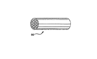
図1を見ると、排出処理システム3は、ライン7を通して随意の第1のTWC触媒9に排気を運ぶガソリンエンジン5を備える。いくつかの場合において、第1のTWC触媒は、ライン11を通って排気流を受容する下流のTWC被覆微粒子フィルター13のために他で必要とされるよりも小さいことが可能である。TWC被覆微粒子フィルター13が完全なTWC機能性を提供する場合において、第1のTWCは必要とされなくてもよい。ライン15は、さらなる処理要素および/またはテール管に通じることができ、そしてシステムの外に出ることができる。他の場合において、TWC被覆微粒子フィルター13は、排出要求を満たすために、第1のTWC触媒と併せて作動するように設計されているTWC触媒充填を含有する。
Referring to FIG. 1, the exhaust treatment system 3 includes a gasoline engine 5 that carries exhaust through a
図2は、TWC触媒セクション32、微粒子フィルターセクション34、随意のNOxトラップ36、およびSCR38を備える統合排出処理システム30を示す。排気ガス排出流の処理中、排気ガスは、未燃焼炭化水素(HC)、一酸化炭素(CO)、窒素酸化物(NOx)、および微粒子物質等の排気ガス排出混入物の処理および/または変換のために、エンジンから統合排出処理システムを通って流れる。排気ガスは、順番に、上流のTWC触媒セクション32、微粒子フィルターセクション34、随意のNOxトラップ36、およびSCR触媒38を通って流れる。代替的な統合システムにおいて、TWC触媒を微粒子フィルター上に被覆することができ、それによって、1つのセクションを排除することができる。
FIG. 2 shows an integrated
良好な活性および長い寿命を示すTWC触媒は、高表面積の耐熱性金属酸化物支持体、例えば、高表面積アルミナ被覆等上に配置される1つ以上の白金族金属(例えば、白金、パラジウム、ロジウム、レニウム、およびイリジウム)を含む。支持体は、耐熱性セラミックもしくは金属ハニカム構造を含むモノリス担体、または適切な耐熱性材料の球体もしくは突出した短いセグメント等の耐熱性粒子等の、適切な担体または基板上に搬送される。耐熱性金属酸化物支持体は、ジルコニア、チタニア、アルカリ土類金属酸化物、例えば、バリア、カルシア、もしくはストロンチア、または最も一般的には希土類金属酸化物、例えば、セリア、ランタナ、および2つ以上の希土類金属酸化物の混合物等の材料によって、熱分解に対して安定化されてもよい。例えば、米国特許第4,171,288号(Keith)を参照。TWC触媒はまた、酸素吸蔵成分を含むように作成することもできる。 A TWC catalyst that exhibits good activity and long life span is one or more platinum group metals (eg, platinum, palladium, rhodium, etc.) disposed on a high surface area refractory metal oxide support, such as a high surface area alumina coating. , Rhenium, and iridium). The support is transported onto a suitable carrier or substrate, such as a monolithic carrier comprising a refractory ceramic or metal honeycomb structure, or refractory particles such as spheres or short protruding segments of a suitable refractory material. The refractory metal oxide support is a zirconia, titania, alkaline earth metal oxide, such as a barrier, calcia, or strontia, or most commonly a rare earth metal oxide, such as ceria, lantana, and two or more It may be stabilized against pyrolysis by a material such as a mixture of rare earth metal oxides. See, for example, U.S. Pat. No. 4,171,288 (Keith). The TWC catalyst can also be made to include an oxygen storage component.
触媒ウォッシュコート層における「支持体」への言及は、会合、分散、含浸、または他の適切な方法によって、貴金属、安定剤、助触媒、結合剤等を受容する材料を指す。支持体の例としては、高表面積耐熱性金属酸化物、および酸素吸蔵成分を含有する複合材料とを含むがこれらに限定されない。高表面耐熱性金属酸化物支持体とは、20Åより大きい細孔および広い細孔分布を有する支持体粒子を指す。高表面積耐熱性金属酸化物支持体、例えば「ガンマアルミナ」または「活性アルミナ」とも呼ばれるアルミナ支持体材料は、典型的には1グラムあたり60平方メートル(「m2/g」)を超える、しばしば最大約200m2/g以上のBET表面積を示す。そのような活性アルミナは、通常、アルミナのガンマおよびデルタ相の混合物であるが、かなりの量のエータ、カッパー、およびシータアルミナ相を含有してもよい。所与の触媒中の触媒成分のうちの少なくともいくつかに対する支持体として、活性アルミナ以外の耐熱性金属酸化物を使用することができる。例えば、バルクセリア、ジルコニア、アルファアルミナ、および他の材料が、そのような使用に対して既知である。これらの材料の多くは、活性アルミナよりもかなり低いBET表面積を有するという欠点があるが、その欠点は、結果として生じる触媒のより大きな耐久性によって相殺される傾向がある。「BET表面積」は、N2吸収によって表面積を判定するためのBrunauer、Emmett、Teller方法を指すその通常の意味を有する。 Reference to “support” in the catalyst washcoat layer refers to a material that accepts noble metals, stabilizers, cocatalysts, binders, etc. by association, dispersion, impregnation, or other suitable method. Examples of the support include, but are not limited to, a high surface area heat-resistant metal oxide and a composite material containing an oxygen storage component. A high surface refractory metal oxide support refers to support particles having pores larger than 20 お よ び and a wide pore distribution. High surface area refractory metal oxide supports, such as alumina support materials, also called “gamma alumina” or “activated alumina”, typically exceed 60 square meters per gram (“m 2 / g”), often up to A BET surface area of about 200 m 2 / g or more is exhibited. Such activated alumina is usually a mixture of the gamma and delta phases of alumina, but may contain significant amounts of eta, copper, and theta alumina phases. As a support for at least some of the catalyst components in a given catalyst, refractory metal oxides other than activated alumina can be used. For example, bulk ceria, zirconia, alpha alumina, and other materials are known for such use. Many of these materials have the disadvantage of having a significantly lower BET surface area than activated alumina, but the disadvantage tends to be offset by the greater durability of the resulting catalyst. “BET surface area” has its ordinary meaning referring to the Brunauer, Emmett, Teller method for determining surface area by N 2 absorption.
1つ以上の実施形態は、アルミナ、アルミナ−ジルコニア、アルミナ−セリア−ジルコニア、ランタナ−アルミナ、ランタナ−ジルコニア−アルミナ、バリア−アルミナ、バリアランタナ−アルミナ、バリアランタナ−ネオジミアアルミナ、およびアルミナ−セリアから成る群から選択される活性化合物を含む高表面積耐熱性金属酸化物支持体を含む。酸素吸蔵成分を含有する複合材料の例としては、セリア−ジルコニアおよびセリア−ジルコニア−ランタナを含むがこれらに限定されない。「セリア−ジルコニア複合材料」への言及は、いずれの成分の量をも指定することなく、セリアおよびジルコニアを含む複合材料を意味する。適切なセリア−ジルコニア複合材料は、例えば、5%、10%、15%、20%、25%、30%、35%、40%、45%、50%、55%、60%、65%、70%、75%、80%、85%、90%、またはさらに95%のセリア含有量を有する複合材料を含むがこれらに限定されない。ある特定の実施形態は、支持体が、100%の名目上のセリア含有量(すなわち、>99%純度)を有するバルクセリアを含むことを提供する。1つ以上の実施形態において、支持体材料は、触媒の酸素吸蔵容量を最大にするために、実質的にアルミナを含まない。「実質的にアルミナを含まない」への言及は、アルミナが、触媒材料の合計充填の5%を超えない量で存在することを意味する。所望される通り、触媒材料は、アルミナを完全に含まないことができ、すなわち、アルミナがないことが可能である。 One or more embodiments include alumina, alumina-zirconia, alumina-ceria-zirconia, lantana-alumina, lantana-zirconia-alumina, barrier-alumina, barrier lantana-alumina, barrier lantana-neodymia alumina, and alumina-ceria. A high surface area refractory metal oxide support comprising an active compound selected from the group consisting of: Examples of composite materials containing oxygen storage components include, but are not limited to, ceria-zirconia and ceria-zirconia-lantana. Reference to “ceria-zirconia composite” means a composite comprising ceria and zirconia, without specifying the amount of any component. Suitable ceria-zirconia composites are, for example, 5%, 10%, 15%, 20%, 25%, 30%, 35%, 40%, 45%, 50%, 55%, 60%, 65%, This includes, but is not limited to, composite materials having a ceria content of 70%, 75%, 80%, 85%, 90%, or even 95%. Certain embodiments provide that the support comprises bulk ceria having a nominal ceria content of 100% (ie,> 99% purity). In one or more embodiments, the support material is substantially free of alumina to maximize the oxygen storage capacity of the catalyst. Reference to “substantially free of alumina” means that the alumina is present in an amount not exceeding 5% of the total charge of the catalyst material. As desired, the catalyst material can be completely free of alumina, ie, free of alumina.
本明細書で使用される場合、ゼオライト等の分子ふるいは、微粒子の形態で触媒貴金属を支持し得る材料を言い、材料は、実質的に均一な細孔分布を有し、平均細孔径は、20Åより大きくない。触媒ウォッシュコート層における「非ゼオライト支持体」への言及は、分子ふるいまたはゼオライトでなく、会合、分散、含浸、または他の適切な方法によって、貴金属、安定剤、助触媒、結合剤等を受容する材料を言う。そのような支持体の例としては、高表面積耐熱性金属酸化物を含むがこれに限定されない。 As used herein, a molecular sieve such as zeolite refers to a material that can support a catalytic noble metal in the form of particulates, the material has a substantially uniform pore distribution, and the average pore size is: It is not larger than 20cm. Reference to “non-zeolite support” in the catalyst washcoat layer accepts noble metals, stabilizers, cocatalysts, binders, etc. by association, dispersion, impregnation, or other suitable method rather than molecular sieves or zeolites. Say the material to do. Examples of such supports include, but are not limited to, high surface area refractory metal oxides.
「含浸された」への言及は、貴金属含有溶液が支持体の細孔内に入ることを意味する。詳細な実施形態において、貴金属の含浸は、初期湿潤によって達成され、ここで希釈された貴金属含有溶液の体積は、支持体本体の細孔容積とおよそ等しい。初期湿潤含浸は、概して、支持体の細孔系全体にわたる前駆物質の溶液の実質的に均一な分布につながる。「密接な接触」への言及は、直接接触する、および/またはOSCがPd成分の前に酸素成分に接触するように実質的に近接する、同じ支持体上のそのような接触(例えば、PdおよびOSC)での有効量の成分を有することを含む。 Reference to “impregnated” means that the noble metal-containing solution enters the pores of the support. In a detailed embodiment, noble metal impregnation is achieved by incipient wetness, wherein the volume of the diluted noble metal-containing solution is approximately equal to the pore volume of the support body. The initial wet impregnation generally leads to a substantially uniform distribution of the precursor solution throughout the pore system of the support. Reference to “intimate contact” refers to such contact (eg, Pd) on the same support that is in direct contact, and / or that the OSC is substantially in contact with the oxygen component prior to the Pd component. And having an effective amount of components in OSC).
TWC触媒材料は、白金族金属および酸素吸蔵成分複合材料を含む第1のウォッシュコートを含むことができる。随意に、フィルターは、何らかの白金族金属含有ウォッシュコートの前に、セリアと、随意に、ランタン、ジルコニウム、プラセオジム、イットリウム、およびネオジムから成る群から選択される安定剤とを含む下地ウォッシュコートで被覆することができる。酸素吸蔵成分は、0.5〜4.0g/in3(30.5g/L〜244g/L)の範囲の量で存在することができる。一実施形態は、アルミナを実質的に含まないTWC触媒材料を提供する。別の実施形態は、TWC触媒材料がNOxトラップ成分を含まないことを提供する。さらに別の実施形態において、TWC触媒材料は、完全有用寿命のエージング後に、少なくとも200mg/Lの酸素を吸蔵する。 The TWC catalyst material can include a first washcoat that includes a platinum group metal and an oxygen storage component composite material. Optionally, the filter is coated with a base washcoat comprising ceria and optionally a stabilizer selected from the group consisting of lanthanum, zirconium, praseodymium, yttrium, and neodymium before any platinum group metal-containing washcoat. can do. The oxygen storage component can be present in an amount ranging from 0.5 to 4.0 g / in 3 (30.5 g / L to 244 g / L). One embodiment provides a TWC catalyst material that is substantially free of alumina. Another embodiment provides that the TWC catalyst material does not include a NOx trap component. In yet another embodiment, the TWC catalyst material occludes at least 200 mg / L of oxygen after full useful life aging.
ゾーン区分実施形態において、触媒微粒子フィルターは、両方ともパラジウム成分を含む上流ゾーンおよび下流ゾーンを含み、上流ゾーンは、下流ゾーン内のパラジウム成分の量よりも多い量のパラジウム成分を含む。一実施例は、上流ゾーン内に20〜100g/ft3(0.7〜3.5g/L)のパラジウムがあり、下流には1〜20g/ft3あることを提供する。 In the zone segment embodiment, the catalyst particulate filter includes an upstream zone and a downstream zone that both contain a palladium component, and the upstream zone contains a greater amount of palladium component than the amount of palladium component in the downstream zone. One embodiment, there is palladium 20 to 100 g / ft 3 in the upstream zone (0.7~3.5g / L), the downstream provide that from 1 to 20 g / ft 3.
微粒子トラップ
微粒子トラップへの言及は、直噴ガソリンエンジンにおける燃焼反応によって生成される微粒子を捕捉するようにサイズ決定および構成されるフィルターを意味する。微粒子の捕捉は、例えば、微粒子(または煤)フィルターの使用によって、微粒子の流れの方向の変化が排気流から微粒子を脱落させるような内部蛇行状経路を有するフロースルー基板の使用によって、波形金属担体等の金属基板の使用によって、または当業者には既知の他の方法によって、起こり得る。排気流から粒子を落とすことができる粗面を伴う管等の、他の濾過デバイスが適切であってもよい。屈曲のある管もまた適切であり得る。
Particulate trap Reference to particulate trap refers to a filter sized and configured to capture particulates produced by the combustion reaction in a direct injection gasoline engine. Particulate capture can be achieved, for example, by the use of a particulate (or soot) filter, by the use of a flow-through substrate having an internal serpentine path such that a change in the direction of particulate flow causes the particulates to fall out of the exhaust stream. Or by other methods known to those skilled in the art. Other filtration devices may be suitable, such as a tube with a rough surface that can drop particles from the exhaust stream. A bent tube may also be appropriate.
フィルターに関して、図3は、微粒子フィルターに適した例示的な壁流フィルター基板の斜視図を示す。TWCまたは酸化触媒組成物を支持するのに有用な壁流基板は、基板の縦軸(または軸長)に沿って延在する、複数の微細な、実質的に平行なガス流路を有する。典型的に、各流路は、基板本体の一端で遮断され、交互の流路は反対側の端面で遮断される。そのようなモノリス担体は、断面1平方インチあたり最大約300の流路(またはセル)を含有してもよいが、それよりかなり少ない数が使用されてもよい。例えば、担体は、約7〜300、より一般的には約200〜300の1平方インチあたりのセル数(「cpsi」)を有してもよい。セルは、長方形、正方形、円形、楕円形、三角形、六角形、または他の多角形である断面を有することができる。壁流基板は、典型的に、0.008〜0.016インチの壁厚を有する。特定の壁流基板は、0.010〜0.012インチの壁厚を有する。被覆がフィルターの軸帳に沿って提供されるように、軸方向のゾーン区分が所望され得る。入口側において、上流端54から測定されると、被覆は、最大50%の軸長(例えば、1〜49.9%、または10〜45%)、50〜75%の軸長、またはさらに100%の軸長まで伸長してもよい。出口側において、下流端56から測定されると、被覆は、最大50%の軸長(例えば、1〜49.9%、または10〜45%)、50〜75%の軸長、またはさらに100%の軸長まで伸長してもよい。
With respect to the filter, FIG. 3 shows a perspective view of an exemplary wall flow filter substrate suitable for a particulate filter. A wall flow substrate useful for supporting a TWC or oxidation catalyst composition has a plurality of fine, substantially parallel gas flow paths extending along the longitudinal axis (or axial length) of the substrate. Typically, each channel is blocked at one end of the substrate body, and alternate channels are blocked at the opposite end face. Such monolithic carriers may contain up to about 300 channels (or cells) per square inch of cross section, although considerably lesser numbers may be used. For example, the carrier may have a cell number per square inch (“cpsi”) of about 7-300, more typically about 200-300. The cells can have a cross section that is rectangular, square, circular, elliptical, triangular, hexagonal, or other polygonal. Wall flow substrates typically have a wall thickness of 0.008 to 0.016 inches. Certain wall flow substrates have a wall thickness of 0.010 to 0.012 inches. An axial zone section may be desired so that a coating is provided along the filter journal. On the inlet side, when measured from the upstream end 54, the coating is up to 50% axial length (eg, 1-49.9%, or 10-45%), 50-75% axial length, or even 100 % Axial length. On the exit side, as measured from the
図3および4は、複数の流路52を有する壁流フィルター基板50を示す。流路は、フィルター基板の内壁53によって管状に囲まれる。基板は、入口または上流端54および出口または下流端56を有する。交互の流路は、入口54および出口56で対向する碁盤の目状を形成するように、入口端において入口栓58で塞がれ、出口端において出口栓60で塞がれる。ガス流62は、上流端54において、塞がれていないチャネル入口64を通って入り、出口栓60によって止められ、(多孔性である)チャネル壁53を通って出口側66へと拡散する。フィルターの入口側の被覆とは、ガス流62が最初に入口被覆に接触するように、被覆が壁53上または壁53内に存在することを意味する。フィルターの出口側の被覆とは、ガス流62が入口被覆の後に出口被覆に接触するように、被覆が壁53上または壁53内に存在することを意味する。ガスは、入口栓58のために、壁の入口側に戻ることはできない。
3 and 4 show a wall
壁流フィルター基板を、菫青石、アルミナ、炭化ケイ素、チタン酸アルミニウム、ムライト等のセラミック様材料で、または耐熱性金属で構成することができる。壁流基板はまた、セラミック繊維複合材料から形成されてもよい。特定の壁流基板は、菫青石、炭化ケイ素、およびチタン酸アルミニウムから形成される。そのような材料は、排気流の処理で遭遇する環境、特に高温に耐えることができる。 The wall flow filter substrate can be composed of a ceramic-like material such as cordierite, alumina, silicon carbide, aluminum titanate, mullite, or a refractory metal. The wall flow substrate may also be formed from a ceramic fiber composite material. Certain wall flow substrates are formed from cordierite, silicon carbide, and aluminum titanate. Such materials can withstand the environments encountered in the treatment of exhaust streams, particularly high temperatures.
本発明のシステムで使用するための壁流基板は、薄い多孔性の壁で囲まれたハニカム(モノリス)を含むことができ、流体流は、大きすぎる背圧または圧力の増加を引き起こすことなく、そこを通って物品を通過する。システムで使用されるセラミック壁流基板は、少なくとも40%(例えば、40〜70%)の多孔度を有する材料で形成することができる。有用な壁流基板は、10ミクロン以上の全体平均細孔径を有することができる。ある特定の壁流基板は、30μmを超えない第1の平均細孔径と、30μmを下回らない第2の平均細孔径とを有する非対称細孔径分布を有する。特定の実施形態において、基板は、少なくとも55%の多孔度、ならびに10〜30ミクロンの範囲の第1の平均細孔径および31〜100ミクロンの範囲の第2の平均細孔径を有することができる。これらの多孔度およびこれらの平均細孔径を伴う基板が、後述する技術で被覆される時、適切なレベルのTWC組成物を、優れた炭化水素、CO、および/またはNOx変換効率を達成するように基板上に充填することができる。これらの基板は、依然として、触媒充填にかかわらず、適切な排気フロー特性、すなわち容認可能な背圧を保持することができる。 A wall flow substrate for use in the system of the present invention can include a honeycomb (monolith) surrounded by a thin porous wall, where the fluid flow does not cause too much back pressure or increased pressure, Pass through the article through it. The ceramic wall flow substrate used in the system can be formed of a material having a porosity of at least 40% (eg, 40-70%). Useful wall flow substrates can have an overall average pore size of 10 microns or greater. Certain wall flow substrates have an asymmetric pore size distribution having a first average pore size that does not exceed 30 μm and a second average pore size that does not fall below 30 μm. In certain embodiments, the substrate can have a porosity of at least 55% and a first average pore size in the range of 10-30 microns and a second average pore size in the range of 31-100 microns. When substrates with these porosities and these average pore sizes are coated with the techniques described below, an appropriate level of TWC composition will be achieved to achieve excellent hydrocarbon, CO, and / or NOx conversion efficiency. Can be filled on the substrate. These substrates can still retain the proper exhaust flow characteristics, ie acceptable back pressure, regardless of catalyst loading.
本発明で使用される多孔性壁流フィルターは、要素の壁が、1つ以上の触媒材料をフィルター上に有する、またはフィルター内に含有するという点において触媒される。触媒材料は、要素壁の入口側のみ、出口側のみ、または入口および出口側の両方に存在してもよく、あるいは壁自体が、触媒材料の全てまたは一部から成ってもよい。本発明は、要素の入口および/または出口壁上での、触媒材料の1つ以上のウォッシュコート、ならびに触媒材料の1つ以上のウォッシュコートの組み合わせの使用を含む。 The porous wall flow filter used in the present invention is catalyzed in that the element walls have or contain one or more catalytic materials on the filter. The catalyst material may be present only on the inlet side of the element wall, only on the outlet side, or on both the inlet and outlet sides, or the wall itself may consist of all or part of the catalyst material. The present invention includes the use of one or more washcoats of catalyst material and a combination of one or more washcoats of catalyst material on the inlet and / or outlet walls of the element.
壁流フィルターをTWCまたは酸化触媒組成物で被覆するために、基板の上部がスラリーの表面のちょうど上方に位置するように、基板は、触媒スラリーの一部に垂直に浸漬される。このようにして、スラリーは、各ハニカム壁の入口面に接触するが、各壁の出口面に接触することはできないように妨げられる。試料は、スラリー中に約30〜60秒間放置される。フィルターは、スラリーから除去され、過剰スラリーは、最初に、チャネルから排出するようにされ、次いで、(スラリー浸透の方向に対して)圧縮空気で吹き、次いで、スラリー浸透の方向から真空にすることによって、壁流フィルターから除去される。この技術を使用することによって、触媒スラリーは、フィルターの壁に浸透するが、過度の背圧が完了フィルター中に蓄積する程度までには、細孔は閉塞されない。本明細書で使用される場合、用語「浸透する」は、フィルター上の触媒スラリーの分散を記述するために使用される場合、触媒組成物がフィルターの壁全体にわたって分散されることを意味する。 In order to coat the wall flow filter with the TWC or oxidation catalyst composition, the substrate is immersed vertically in a portion of the catalyst slurry so that the top of the substrate is located just above the surface of the slurry. In this way, the slurry contacts the inlet face of each honeycomb wall but is prevented from contacting the outlet face of each wall. The sample is left in the slurry for about 30-60 seconds. The filter is removed from the slurry and excess slurry is first allowed to drain from the channel, then blown with compressed air (relative to the direction of slurry infiltration) and then evacuated from the direction of slurry infiltration Is removed from the wall flow filter. By using this technique, the catalyst slurry penetrates the filter walls, but the pores are not occluded to the extent that excessive back pressure accumulates in the finished filter. As used herein, the term “permeate” when used to describe the dispersion of a catalyst slurry on a filter means that the catalyst composition is dispersed across the walls of the filter.
被覆フィルターは、典型的に、約100℃で乾燥し、より高い温度(例えば、300〜450℃および最大590℃)で焼成される。焼成後、触媒充填を、フィルターの被覆重量および非被覆重量の計算によって判定することができる。当業者には明らかなように、被覆スラリーの固形分を変化させることによって、触媒充填を変更することができる。代替的に、被覆スラリーにおいてフィルターの繰り返し浸漬を行うことができ、続いて、上述のように過剰スラリーを除去することができる。 Coated filters are typically dried at about 100 ° C and fired at higher temperatures (eg, 300-450 ° C and up to 590 ° C). After calcination, catalyst loading can be determined by calculating the coated and uncoated weights of the filter. As will be apparent to those skilled in the art, the catalyst loading can be altered by changing the solids content of the coating slurry. Alternatively, the filter can be repeatedly dipped in the coating slurry, followed by removal of excess slurry as described above.
金属基板に関して、有用な基板は、1つ以上の金属または金属合金で構成されてもよい。金属担体は、波形シートまたはモノリス形態等の種々の形で利用されてもよい。特定の金属支持体は、チタンまたはステンレス鋼等の耐熱金属および金属合金、ならびに鉄が大きな、または主な成分である他の合金を含む。そのような合金は、ニッケル、クロムおよび/またはアルミニウムのうちの1つ以上を含有してもよく、これらの金属の総量は、合金の少なくとも15重量%、例えば、10〜25重量%のクロム、3〜8重量%のアルミニウム、および最大20重量%のニッケルを有利に含んでもよい。合金はまた、マンガン、銅、バナジウム、チタン等の、少量または微量の1つ以上の他の金属を含有してもよい。担体の表面上に酸化層形成することによって、合金の腐食に対する耐性を向上させるために、金属担体の表面は、高温で、例えば、1000℃で酸化されてもよい。そのような高温で誘発された酸化は、担体の触媒材料の粘着性を増強させ得る。 With respect to metal substrates, useful substrates may be composed of one or more metals or metal alloys. The metal support may be utilized in various forms such as corrugated sheets or monolithic forms. Particular metal supports include refractory metals and metal alloys such as titanium or stainless steel, and other alloys in which iron is a major or major component. Such alloys may contain one or more of nickel, chromium and / or aluminum, and the total amount of these metals is at least 15% by weight of the alloy, for example 10-25% chromium, 3 to 8% by weight of aluminum and up to 20% by weight of nickel may advantageously be included. The alloy may also contain minor or minor amounts of one or more other metals such as manganese, copper, vanadium, titanium, and the like. In order to improve the resistance of the alloy to corrosion by forming an oxide layer on the surface of the support, the surface of the metal support may be oxidized at a high temperature, for example 1000 ° C. Such high temperature induced oxidation can enhance the stickiness of the support catalyst material.
触媒複合材料ウォッシュコートの調製
触媒複合材料は、単一層状または多数の層状で形成されてもよい。いくつかの場合において、触媒材料の1つのスラリーを調製し、担体上で多数の層を形成するためにこのスラリーを使用することが適切であり得る。複合材料は、当技術分野において既知の工程によって容易に調製することができる。代表的な工程を以下に記載する。本明細書で使用する場合、用語「ウォッシュコート」は、処理されるガス流が通過するのを可能とするのに十分に多孔性であるハニカム型の担体部材の基板担体材料に適用される触媒材料または他の材料の薄い粘着性の被覆分野におけるその通常の意味を有する。したがって、「ウォッシュコート層」は、支持体粒子で構成される被覆として定義される。「触媒ウォッシュコート層」は、触媒成分で含浸される支持体粒子で構成される被覆である。
Preparation of catalyst composite washcoat The catalyst composite may be formed in a single layer or multiple layers. In some cases it may be appropriate to prepare one slurry of the catalyst material and use this slurry to form multiple layers on the support. Composite materials can be readily prepared by processes known in the art. A typical process is described below. As used herein, the term “washcoat” refers to a catalyst applied to the substrate support material of a honeycomb-type support member that is sufficiently porous to allow the gas stream being processed to pass through. It has its usual meaning in the field of thin sticky coating of materials or other materials. Thus, a “washcoat layer” is defined as a coating composed of support particles. The “catalyst washcoat layer” is a coating composed of support particles impregnated with a catalyst component.
触媒複合材料は、担体上に層状で容易に調製することができる。特定のウォッシュコートの第1の層では、ガンマアルミナ等の高表面積耐熱性金属酸化物の微粉粒子が、適切な媒体中、例えば、水中でスラリー化される。貴金属(例えば、パラジウム、ロジウム、白金、および/またはそれらの組み合わせ)、安定剤、および/または助触媒等の成分を取り込むために、そのような成分は、水溶性または水分散性化合物または複合物の混合物としてスラリーに取り込まれてもよい。典型的に、パラジウムが所望される場合、パラジウム成分は、耐熱性金属酸化物支持体、例えば、活性アルミナ上で成分の分散を達成するために、化合物または複合物の形態で利用される。用語「パラジウム成分」とは、その焼成または使用の際に、触媒的に活性な形態、通常、金属または金属酸化物に分解するか、そうでなければ変換する何らかの化合物、複合物等を意味する。金属成分の水溶性化合物もしくは水分散性化合物または複合体は、金属成分を耐熱性金属酸化物支持体粒子上に含浸または堆積するために使用される液体媒体が、触媒組成物中に存在し得る金属もしくはその化合物もしくはその複合物または他の成分と不利に反応せず、加熱および/または真空を適用すると、揮発または分解によって金属成分から除去されることが可能な限り、使用することができる。いくつかの場合において、触媒が使用され、動作時に遭遇する高温にさらされるまで、液体の除去の完了は起こらない場合がある。概して、経済および環境態様の両方の観点から、貴金属の可溶性化合物または複合物の水溶液が利用される。例えば、適切な化合物は、硝酸パラジウムまたは硝酸ロジウムである。 The catalyst composite material can be easily prepared in layers on a support. In the first layer of a particular washcoat, fine particles of high surface area refractory metal oxide, such as gamma alumina, are slurried in a suitable medium, eg, water. To incorporate components such as noble metals (eg, palladium, rhodium, platinum, and / or combinations thereof), stabilizers, and / or promoters, such components are water soluble or water dispersible compounds or composites. May be incorporated into the slurry as a mixture. Typically, where palladium is desired, the palladium component is utilized in the form of a compound or composite to achieve dispersion of the component on a refractory metal oxide support, such as activated alumina. The term “palladium component” means any compound, composite, etc. that decomposes or otherwise converts to a catalytically active form, usually a metal or metal oxide, during its calcination or use. . The water-soluble compound or water-dispersible compound or composite of the metal component may be present in the catalyst composition in a liquid composition used to impregnate or deposit the metal component on the refractory metal oxide support particles. It can be used as long as it does not adversely react with the metal or its compounds or its composites or other components and can be removed from the metal components by volatilization or decomposition upon application of heat and / or vacuum. In some cases, completion of liquid removal may not occur until the catalyst is used and exposed to the high temperatures encountered during operation. In general, aqueous solutions of soluble compounds or composites of precious metals are utilized from both economic and environmental aspects. For example, a suitable compound is palladium nitrate or rhodium nitrate.
本発明の積層触媒複合材料の任意の層を調製する適切な方法は、所望の貴金属化合物(例えば、パラジウム化合物)の溶液と、微粉化された高表面積耐熱性金属酸化物支持体、例えば、被覆可能なスラリーを形成するために後に水と組み合わせて湿潤固体を形成するために、溶液の実質的に全てを吸収するのに十分に乾燥しているガンマアルミナ等の少なくとも1つの支持体との混合物を調製することである。1つ以上の実施形態において、スラリーは、酸性であり、例えば、約2から約7未満のpHを有する。スラリーのpHは、適量の無機酸または有機酸のスラリーへの添加によって低下させてもよい。酸および原材料の適合性が考慮される場合、両方の組み合わせを使用することができる。無機酸は、硝酸を含むがこれに限定されない。有機酸は、酢酸、プロピオン酸、シュウ酸、マロン酸、コハク酸、グルタミン酸、アジピン酸、マレイン酸、フマル酸、フタル酸、酒石酸、クエン酸等を含むがこれらに限定されない。その後、所望される場合、酸素吸蔵成分の水溶性または水分散性化合物、例えば、セリウム−ジルコニウム複合体、安定剤、例えば、酢酸バリウム、および助触媒、例えば、硝酸ランタンをスラリーに添加してもよい。 Suitable methods for preparing any layer of the laminated catalyst composite of the present invention include a solution of the desired noble metal compound (eg, palladium compound) and a micronized high surface area refractory metal oxide support, eg, coating. A mixture with at least one support, such as gamma alumina, that is sufficiently dry to absorb substantially all of the solution to later form a wet solid in combination with water to form a possible slurry. Is to prepare. In one or more embodiments, the slurry is acidic, eg, has a pH of about 2 to less than about 7. The pH of the slurry may be lowered by adding an appropriate amount of an inorganic or organic acid to the slurry. A combination of both can be used if the compatibility of the acid and raw materials is considered. Inorganic acids include but are not limited to nitric acid. Organic acids include, but are not limited to, acetic acid, propionic acid, oxalic acid, malonic acid, succinic acid, glutamic acid, adipic acid, maleic acid, fumaric acid, phthalic acid, tartaric acid, citric acid and the like. Thereafter, if desired, a water-soluble or water-dispersible compound of the oxygen storage component, such as a cerium-zirconium complex, a stabilizer such as barium acetate, and a cocatalyst such as lanthanum nitrate may be added to the slurry. Good.
一実施形態において、スラリーは、その後、平均直径で約30ミクロン未満、すなわち、約0.1〜15ミクロンの粒径を有する固体の実質的に全てをもたらすように粉砕される。粉砕は、ボールミル、サーキュラーミル、または他の同様の機器で達成されてもよく、スラリーの固形分は、例えば、約20〜60重量%、より具体的には、約30〜40重量%であってもよい。 In one embodiment, the slurry is then ground to yield substantially all of the solid having an average diameter of less than about 30 microns, ie, a particle size of about 0.1 to 15 microns. Milling may be accomplished with a ball mill, circular mill, or other similar equipment, where the solids content of the slurry is, for example, about 20-60% by weight, more specifically about 30-40% by weight. May be.
追加の層、すなわち、第2および第3の層を調製して、担体上への第1の層の堆積のために上述した方法と同じ方法で、第1の層上に堆積されてもよい。 Additional layers, ie second and third layers, may be prepared and deposited on the first layer in the same manner as described above for the deposition of the first layer on the support. .
以下の非限定的な実施例は、本発明の種々の実施形態を例示するのに用いられるものとする。実施例のそれぞれにおいて、担体は、菫青石である。 The following non-limiting examples shall be used to illustrate various embodiments of the present invention. In each of the examples, the carrier is cordierite.
実施例1
比較
1g/in3(61g/L)のウォッシュコート充填を伴うハニカムフロースルー基板上の三元変換(TWC)触媒を調製した。フロースルー基板は、4.66*5”のサイズ、300/12cpsi、1.4L容積、30g/ft3白金族金属(PGM)、および0/27/3のPt/Pd/RhのPGM比率を有した。
Example 1
Comparison A three-way conversion (TWC) catalyst on a honeycomb flow-through substrate with 1 g / in 3 (61 g / L) washcoat filling was prepared. The flow-through substrate has a 4.66 * 5 ″ size, 300/12 cpsi, 1.4 L volume, 30 g / ft 3 platinum group metal (PGM), and a Pt / Pd / Rh PGM ratio of 0/27/3. Had.
実施例2
基板壁内に三元変換(TWC)触媒を有する低多孔度の粒子フィルターを、1g/in3(61g/L)、2g/in3(122g/L(2g/in3)、および3g/in3(183g/L)のウォッシュコート充填で調製した。フィルター基板は、4.66*5”のサイズ、300/12cpsi、1.4L容積、30g/ft3白金族金属(PGM)、および0/27/3のPt/Pd/RhのPGM比率を有した。フィルター基板は、45%の多孔度および13μmの平均細孔径を有した。
Example 2
Low porosity particle filters with a three-way conversion (TWC) catalyst in the substrate wall are 1 g / in 3 (61 g / L), 2 g / in 3 (122 g / L (2 g / in 3 ), and 3 g / in). 3 (183 g / L) washcoat fill. The filter substrate was 4.66 * 5 ″ size, 300/12 cpsi, 1.4 L volume, 30 g / ft 3 platinum group metal (PGM), and 0 / The PGM ratio was 27/3 Pt / Pd / Rh The filter substrate had a porosity of 45% and an average pore diameter of 13 μm.
実施例3
基板壁内に三元変換(TWC)触媒を有する高多孔度の粒子フィルターを、1g/in3(61g/L)、2g/in3(122g/L)、および3g/in3(183g/L)のウォッシュコート充填で調製した。フィルター基板は、4.66*5”のサイズ、300/12cpsi、1.4L容積、30g/ft3白金族金属(PGM)、および0/27/3のPt/Pd/RhのPGM比率を有した。フィルター基板は、65%の多孔度および20μmの平均細孔径を有した。
Example 3
Highly porous particle filters having a three-way conversion (TWC) catalyst in the substrate wall were obtained at 1 g / in 3 (61 g / L), 2 g / in 3 (122 g / L), and 3 g / in 3 (183 g / L). ). The filter substrate has a size of 4.66 * 5 ", 300/12 cpsi, 1.4 L volume, 30 g / ft 3 platinum group metal (PGM), and a PGM ratio of 0/27/3 Pt / Pd / Rh. The filter substrate had a porosity of 65% and an average pore diameter of 20 μm.
実施例4
それぞれ1g/in3(61g/L)を有する実施例1、2、および3の複合体を、2%O2、10%H2O、および残りの割合のN2で900℃の熱水オーブンエージング下で4時間エージングした。New European Drive Cycle(NEDC)条件と、密結合位置にあるガソリン直噴エンジンの下流に位置する複合体を伴う1.6Lエンジン下で、PMPプロトコルを使用して微粒子数を測定した(表1)。非メタン炭化水素(NMHC)、全炭化水素(HC)、一酸化炭素(CO)、およびNOxの排出もまた測定した(表1)。
Example 4
The composites of Examples 1, 2, and 3, each having 1 g / in 3 (61 g / L), were heated at 900 ° C. with 2% O 2 , 10% H 2 O, and the remaining proportion of N 2 at 900 ° C. Aged for 4 hours under aging. Particle counts were measured using the PMP protocol under a 1.6L engine with a New European Drive Cycle (NEDC) condition and a complex located downstream of a gasoline direct injection engine in a tightly coupled position (Table 1) . Nonmethane hydrocarbons (NMHC), total hydrocarbons (HC), carbon monoxide (CO), and NOx emissions were also measured (Table 1).

実施例2および3の被覆フィルターに対するTWC触媒効率は、比較実施例1と比較して有意に低い。しかしながら、実施例1の比較フロースルー基板は、濾過効率を示さない。1g/in3(61g/L)のウォッシュコート充填での実施例2の低多孔度フィルターは、Euro6基準を満たした。実施例2および3の背圧を、NEDCのEUDCセグメント中に評価した。実施例2に対する背圧は、実施例3と比較して有意に高かった。
The TWC catalytic efficiency for the coated filters of Examples 2 and 3 is significantly lower compared to Comparative Example 1. However, the comparative flow-through substrate of Example 1 does not show filtration efficiency. The low porosity filter of Example 2 with 1 g / in 3 (61 g / L) washcoat fill met
実施例5
様々なウォッシュコート充填での実施例2の複合体を、1000℃の発熱エージング下で80時間エージングした。New European Drive Cycle(NEDC)条件と、密結合位置にあるガソリン直噴エンジンの下流に位置する複合体を伴う1.6Lエンジン下で、PMPプロトコルを使用して微粒子数を測定した(表2a)。微粒子量、全炭化水素(HC)、一酸化炭素(CO)、およびNOxの排出もまた測定した(表2a)。
Example 5
The composite of Example 2 with various washcoat fills was aged for 80 hours under exothermic aging at 1000 ° C. Particle counts were measured using the PMP protocol under a 1.6L engine with a New European Drive Cycle (NEDC) condition and a complex located downstream of a gasoline direct injection engine in a tightly coupled position (Table 2a) . Particulate amount, total hydrocarbon (HC), carbon monoxide (CO), and NOx emissions were also measured (Table 2a).
ウォッシュコート充填を増加させることにより、高多孔度フィルターは、Euro6微粒子数規制より十分低くなった。フィルターの全ての微粒子排出は、Euro6基準を容易に満たした。より多いウォッシュコート充填は、排出、特に、NOxを減少させた。2g/in3充填での高多孔度フィルターの実施例3に対する背圧は、実施例2で提供されたような低多孔度の非被覆フィルターと同様であった。
By increasing the washcoat filling, the high porosity filter was well below the
実施例3の高多孔度フィルターの充填の多孔度の4.66×4.5”のフィルター基板もまた、1000℃の発熱エージング下で80時間エージングし、それらの酸素吸蔵容量を試験した。表2bは、501℃/26.1kg/hでの前部/後部センサー遅延時間過濃/希薄に基づいて計算された、データの要約を提供する。 The porous 4.66 × 4.5 ″ filter substrate packed in the high porosity filter of Example 3 was also aged under 1000 ° C. exothermic aging for 80 hours to test their oxygen storage capacity. 2b provides a summary of data calculated based on front / rear sensor lag time over / lean at 501 ° C./26.1 kg / h.
ウォッシュコート充填の増加は、酸素吸蔵容量もまた増加させる。 Increasing washcoat filling also increases the oxygen storage capacity.
実施例6
1g/in3(122g/L)および3g/in3(183g/L)を有する被覆フィルターを、60g/ft3貴金属を有するフロースルー基板上の密結合のTWC触媒と組み合わせた。これらを、フロースルー基板(CC)上に密結合のTWC触媒のみを有するか、またはアンダーフロア(UF)TWCと組み合わせてフロースルー基板上に密結合のTWC触媒を有する、比較システムとともに、CO2排出に対して試験した。アンダーフロア位置にあるガソリン直噴エンジンの下流に位置する複合体を伴う2.0Lエンジンに関する個々のNEDC評価結果を、表3に提供する。
Example 6
Coated filters with 1 g / in 3 (122 g / L) and 3 g / in 3 (183 g / L) were combined with a tightly coupled TWC catalyst on a flow-through substrate with 60 g / ft 3 noble metal. These can be combined with a comparison system that has only a tightly-coupled TWC catalyst on the flow-through substrate (CC), or a tightly-coupled TWC catalyst on the flow-through substrate in combination with an underfloor (UF) TWC, together with a CO 2 Tested for emissions. The individual NEDC evaluation results for the 2.0 L engine with the composite located downstream of the gasoline direct injection engine in the underfloor position are provided in Table 3.
TWC触媒のみのシステムと比較して、被覆微粒子フィルターと組み合わせた密結合のTWC触媒に対する同様のレベルのCO2排出は、NEDCテスト条件下で燃料に不利な条件を示さなかった。 Compared to the TWC catalyst only system, similar levels of CO 2 emissions for the tightly coupled TWC catalyst in combination with the coated particulate filter did not show fuel adverse conditions under NEDC test conditions.
実施例7
実施例3の2g/in3(122g/L)充填を添加して、実施例6のシステムを、次いで、1000℃の発熱エージング下で80時間エージングした。New European Drive Cycle(NEDC)条件と、アンダーフロア位置にあるガソリン直噴エンジンの下流に位置する複合体を伴う2.0Lエンジン下で、全炭化水素(HC)、一酸化炭素(CO)、およびNOxを測定した(表4)。
Example 7
The 2 g / in 3 (122 g / L) charge of Example 3 was added and the system of Example 6 was then aged for 80 hours under 1000 ° C. exothermic aging. Under a 2.0 L engine with New European Drive Cycle (NEDC) conditions and a complex located downstream of a gasoline direct injection engine in an underfloor position, total hydrocarbons (HC), carbon monoxide (CO), and NOx was measured (Table 4).
アンダーフロー(UF)TWCまたは被覆微粒子フィルターの添加は、システムがEuro6排出基準を満たすことを可能にした。
The addition of underflow (UF) TWC or coated particulate filter allowed the system to meet
実施例8
密結合位置にある60g/ft3白金族金属TWC触媒および3g/in3被覆微粒子フィルターのシステムを、1000℃発熱エージング下で80時間エージングし、2.0Lエンジンを使用して、繰り返しNEDCテスト下で試験した。表5は、3回の試験後の被覆フィルターに対する微粒子数を示す。次いで、この被覆フィルターを、約130km/hの最大速度を有し、700℃に到達する、15分の模擬ハイウェイ走行、多重加速、および燃料削減の再生活性にさらした。次いで、NEDCテストを、さらに4回繰り返した。
Example 8
A system of 60 g / ft 3 platinum group metal TWC catalyst and 3 g / in 3 coated particulate filter in a tightly coupled position was aged for 80 hours under 1000 ° C. exothermic aging and repeatedly subjected to NEDC testing using a 2.0 L engine. Tested. Table 5 shows the number of particulates for the coated filter after three tests. The coated filter was then exposed to a 15 minute simulated highway run, multiple accelerations, and fuel reduction regeneration activity with a maximum speed of about 130 km / h and reaching 700 ° C. The NEDC test was then repeated four more times.
表5は、微粒子フィルターの濾過効率が経時的に向上したことを示す。加えて、被覆フィルターを予想ハイウェイ走行条件下で再生できることが示されている。再生事象後、HC、CO、またはNOx変換に影響を及ぼさないことを示す排出データもまた得られた。 Table 5 shows that the filtration efficiency of the particulate filter improved over time. In addition, it has been shown that the coated filter can be regenerated under expected highway driving conditions. Emission data was also obtained that showed no effect on HC, CO, or NOx conversion after the regeneration event.
実施例9
実施例3の様々な充填の被覆微粒子フィルターを、アンダーフロア位置にあるガソリン直噴エンジンの下流に位置する複合体を伴う2.0Lエンジンを使用して、繰り返しNEDCテスト下で試験した。表6は、被覆フィルターに対する微粒子数を示す。
Example 9
The various packed coated particulate filters of Example 3 were tested repeatedly under NEDC test using a 2.0 L engine with a composite located downstream of a gasoline direct injection engine in the underfloor position. Table 6 shows the number of fine particles for the coated filter.
ウォッシュコート充填が増加すると、アンダーフロア位置にある高多孔度フィルターの濾過効率は向上した。 As washcoat filling increased, the filtration efficiency of the high porosity filter in the underfloor position improved.
実施例10
基板壁上または基板壁内に三元変換(TWC)触媒を有する触媒粒子フィルターを、様々なゾーン区分構成の2g/in3(122g/L)のウォッシュコート充填で調製した。非被覆フィルター基板は、20μmの平均細孔径を有し、4.66*5”のサイズ、300/12cpsi、1.4L容積を有した。ウォッシュコートは、60g/ft3白金族金属(PGM)および0/57/3のPt/Pd/RhのPGM比率を含有した。表7は、実施例10A、10B、および10Cのウォッシュコートと、非被覆フィルターと比較した、結果として生じるフィルターとの要約を提供する。多孔度に関して、前部、中央部、および後部を含むフィルターのセクションを試験した。中央部は、基板全体のごく一部であった。フィルターの多孔度は、通常、前部および後部の多孔度測定の平均から得られる。非対称粒径分布を有した、実施例10Cで列挙したd50およびd90粒径に関して、それらは、2つの単峰性分布の和に相当する。
Example 10
Catalyst particle filters with a three-way conversion (TWC) catalyst on or in the substrate wall were prepared with 2 g / in 3 (122 g / L) washcoat filling of various zone section configurations. The uncoated filter substrate had an average pore size of 20 μm, a size of 4.66 * 5 ″, 300/12 cpsi, 1.4 L volume. The washcoat was 60 g / ft 3 platinum group metal (PGM). And Pt / Pd / Rh PGM ratio of 0/57/3 Table 7 summarizes the washcoats of Examples 10A, 10B, and 10C and the resulting filter compared to the uncoated filter The section of the filter, including the front, middle, and rear, was tested for porosity, which was a small part of the entire substrate. Obtained from the average of the posterior porosity measurements.For the d50 and d90 particle sizes listed in Example 10C with an asymmetric particle size distribution, they are two unimodal distributions. Is equivalent to the sum of
実施例11
実施例10の触媒フィルターを、1000℃の発熱エージング下で80時間エージングした。New European Drive Cycle(NEDC)条件と、密結合位置にあるガソリン直噴エンジンの下流に位置する複合体を伴う1.6Lエンジン下で、PMPプロトコルを使用して微粒子数を測定した(表8)。微粒子量、全炭化水素(HC)、一酸化炭素(CO)、およびNOxの排出もまた測定した(表8)。多孔度の背圧への影響を図5に提供する。
Example 11
The catalyst filter of Example 10 was aged for 80 hours under exothermic aging at 1000 ° C. Particle counts were measured using the PMP protocol under a 1.6L engine with a New European Drive Cycle (NEDC) condition and a complex located downstream of a gasoline direct injection engine in a tightly coupled position (Table 8) . Particulate amount, total hydrocarbon (HC), carbon monoxide (CO), and NOx emissions were also measured (Table 8). The effect of porosity on back pressure is provided in FIG.
表8のデータは、2つの平均粒径を有し、入口で100%被覆され、出口で100%被覆されるウォッシュコートを有する実施例10Cのより高い多孔度の触媒フィルターが、実施例10Aと比較して、一定の全充填で、より低いNOx、CO、およびHC変換を提供することを示す。実施例10Cのウォッシュコートで濾過効率もまた向上する。 The data in Table 8 shows that the higher porosity catalytic filter of Example 10C with two average particle sizes, having a washcoat that is 100% coated at the inlet and 100% coated at the outlet, By comparison, it is shown that constant NOF provides lower NOx, CO, and HC conversion. Filtration efficiency is also improved with the washcoat of Example 10C.
実施例12
基板壁上または基板壁内に三元変換(TWC)触媒を有する触媒粒子フィルターを、様々なゾーン区分構成の2g/in3(122g/L)のウォッシュコート充填で調製した。非被覆フィルター基板は、20μmの平均細孔径を有し、4.66*5”のサイズ、300/12cpsi、1.4L容積を有した。ウォッシュコートは、60g/ft3白金族金属(PGM)、および0/57/3のPt/Pd/RhのPGM比率を含有した。表9は、実施例12A、12B、12C、および12Dのウォッシュコートと、結果として生じるフィルターとの要約を提供する。非被覆フィルターは、表7に示したものである。多孔度に関して、前部、中央部、および後部を含むフィルターのセクションを試験した。中央部は、基板全体のごく一部であった。フィルターの多孔度は、通常、前部および後部の多孔度測定の平均から得られる。非対称粒径分布を有する、実施例12A、12B、12C、および12Dで列挙したd50およびd90粒径に関して、それらは、2つの単峰性分布の和に相当する。
Example 12
Catalyst particle filters with a three-way conversion (TWC) catalyst on or in the substrate wall were prepared with 2 g / in 3 (122 g / L) washcoat filling of various zone section configurations. The uncoated filter substrate had an average pore size of 20 μm, a size of 4.66 * 5 ″, 300/12 cpsi, 1.4 L volume. The washcoat was 60 g / ft 3 platinum group metal (PGM). And a PGM ratio of 0/57/3 Pt / Pd / Rh Table 9 provides a summary of the washcoats of Examples 12A, 12B, 12C, and 12D and the resulting filters. The uncoated filters are shown in Table 7. The sections of the filter including the front, middle and back were tested for porosity, which was a small part of the entire substrate. The porosity of is usually obtained from an average of the front and back porosity measurements, d listed in Examples 12A, 12B, 12C, and 12D, having an asymmetric particle size distribution. For 50 and d90 particle sizes, they correspond to the sum of two unimodal distributions.
実施例13
実施例12の触媒フィルターを、1000℃の発熱エージング下で80時間エージングする。New European Drive Cycle(NEDC)条件と、密結合位置にあるガソリン直噴エンジンの下流に位置する複合体を伴う1.6Lエンジン下で、PMPプロトコルを使用して微粒子数を測定する。微粒子量、全炭化水素(HC)、一酸化炭素(CO)、およびNOxの排出もまた測定する。
Example 13
The catalyst filter of Example 12 is aged for 80 hours under exothermic aging at 1000 ° C. Particle counts are measured using the PMP protocol under a 1.6 L engine with New European Drive Cycle (NEDC) conditions and a complex located downstream of a gasoline direct injection engine in a tightly coupled position. The amount of particulates, total hydrocarbons (HC), carbon monoxide (CO), and NOx emissions are also measured.
実施例14
触媒材料を有する粒子フィルターを、第1の入口コートおよび第2の入口コートの2つのコートを使用して調製する。三元変換(TWC)触媒複合材料は、上流ゾーンが下流ゾーンよりも多くのパラジウムを有するように、パラジウムを含有する。コートを以下の通りに調製する。
Example 14
A particle filter with catalyst material is prepared using two coats, a first inlet coat and a second inlet coat. A ternary conversion (TWC) catalyst composite contains palladium such that the upstream zone has more palladium than the downstream zone. The coat is prepared as follows.
第1の入口コート
第1の入口コートに存在する成分は、45重量%のセリアおよびパラジウムを有するセリア−ジルコニア複合材料である。第1の入口コートは、フィルターの全長に沿って提供される。被覆後、フィルターおよび第1の入口コートを乾燥し、次いで、550℃の温度で1時間焼成する。
First Inlet Coat The component present in the first inlet coat is a ceria-zirconia composite with 45% by weight ceria and palladium. A first inlet coat is provided along the entire length of the filter. After coating, the filter and first inlet coat are dried and then baked at a temperature of 550 ° C. for 1 hour.
第2の入口コート
第2の入口コートは、上流ゾーンを形成するように、上流端から開始してフィルターの長さに沿って、浸漬として、またはウォッシュコートスラリーとして適用される、パラジウムを含む。適用後、フィルターおよび第1の入口コートおよび第2の入口コートを乾燥し、次いで、550℃の温度で1時間焼成する。
Second Inlet Coat The second inlet coat includes palladium that is applied from the upstream end along the length of the filter as a dip or as a washcoat slurry to form an upstream zone. After application, the filter and the first and second inlet coats are dried and then baked at a temperature of 550 ° C. for 1 hour.
実施例15
触媒材料を有する粒子フィルターを、入口コートおよび出口コートの2つのコートを使用して調製する。三元変換(TWC)触媒複合材料は、パラジウムおよびロジウムを含有する。コートを以下の通りに調製する。
入口コート
Example 15
A particle filter with catalyst material is prepared using two coats, an inlet coat and an outlet coat. A ternary conversion (TWC) catalyst composite contains palladium and rhodium. The coat is prepared as follows.
Entrance court
第1の入口コートに存在する成分は、パラジウムであり、このコートはセリアを含まない。被覆後、フィルタープラス入口コートを乾燥し、次いで、550℃の温度で1時間焼成する。 The component present in the first inlet coat is palladium, which does not contain ceria. After coating, the filter plus inlet coat is dried and then baked at a temperature of 550 ° C. for 1 hour.
出口コート
出口コートは、ロジウムと、45重量%のセリアを有するセリア−ジルコニア複合材料とを含む。適用後、フィルターおよび入口コートと出口コートを乾燥し、次いで、550℃の温度で1時間焼成する。
Exit Coat The exit coat comprises rhodium and a ceria-zirconia composite having 45% by weight ceria. After application, the filter and inlet and outlet coats are dried and then baked at a temperature of 550 ° C. for 1 hour.
実施例16
触媒材料を有する粒子フィルターを、入口コートおよび出口コートの2つのコートを使用して調製する。三元変換(TWC)触媒複合材料は、白金およびロジウムを含有する。コートを以下の通りに調製する。
入口コート
Example 16
A particle filter with catalyst material is prepared using two coats, an inlet coat and an outlet coat. A ternary conversion (TWC) catalyst composite contains platinum and rhodium. The coat is prepared as follows.
Entrance court
第1の入口コートに存在する成分は、白金と、NOx捕捉材料としてのバリウムである。被覆後、フィルタープラス入口コートを乾燥し、次いで、550℃の温度で1時間焼成する。 The components present in the first inlet coat are platinum and barium as a NOx trapping material. After coating, the filter plus inlet coat is dried and then baked at a temperature of 550 ° C. for 1 hour.
出口コート
出口コートは、ロジウムと、45重量%のセリアを有するセリア−ジルコニア複合材料とを含む。適用後、フィルタープラス入口コートおよび出口コートを乾燥し、次いで、550℃の温度で1時間焼成する。
Exit Coat The exit coat comprises rhodium and a ceria-zirconia composite having 45% by weight ceria. After application, the filter plus inlet coat and outlet coat are dried and then baked at a temperature of 550 ° C. for 1 hour.
実施例17
触媒材料を有する粒子フィルターを、入口コートおよび出口コートの2つのコートを使用して調製する。三元変換(TWC)触媒複合材料は、白金およびパラジウムを含有する。コートを以下の通りに調製する。
Example 17
A particle filter with catalyst material is prepared using two coats, an inlet coat and an outlet coat. A ternary conversion (TWC) catalyst composite contains platinum and palladium. The coat is prepared as follows.
入口コート
第1の入口コートに存在する成分は、パラジウムであり、このコートはセリアを含まない。被覆後、フィルタープラス入口コートを乾燥し、次いで、550℃の温度で1時間焼成する。
Inlet coat The component present in the first inlet coat is palladium, which does not contain ceria. After coating, the filter plus inlet coat is dried and then baked at a temperature of 550 ° C. for 1 hour.
出口コート
出口コートは、白金と、45重量%のセリアを有するセリア−ジルコニア複合材料と、炭化水素捕捉材料であるゼオライトとを含む。適用後、フィルタープラス入口コートおよび出口コートを乾燥し、次いで、550℃の温度で1時間焼成する。
Exit Coat The exit coat comprises platinum, a ceria-zirconia composite having 45% by weight ceria, and a zeolite that is a hydrocarbon scavenger material. After application, the filter plus inlet coat and outlet coat are dried and then baked at a temperature of 550 ° C. for 1 hour.
実施例18
触媒材料を有する粒子フィルターを、1つの入口コートを使用して調製する。入口コートは、第1の平均粒径が30μm以下であり、第2の粒径が30μmを超えるような、二峰性粒径分布を有する。粒子フィルターは、第1の平均細孔径が30μm以下であり、第2の細孔径が30μmを超えるような、二峰性細孔径分布を有する。
Example 18
A particle filter with catalyst material is prepared using one inlet coat. The inlet coat has a bimodal particle size distribution such that the first average particle size is 30 μm or less and the second particle size is greater than 30 μm. The particle filter has a bimodal pore size distribution such that the first average pore size is 30 μm or less and the second pore size is greater than 30 μm.
実施例19
触媒材料を有する粒子フィルターを、2つの入口コートを使用して調製する。第1の入口コートは、第1の単峰性粒径分布を有し、平均粒径は30μm以下であり、上流端から入口の50%に沿って被覆される。第2の入口コートは、第2の単峰性粒径分布を有し、平均粒径は30μmを超え、フィルターの全長を被覆される。粒子フィルターは、第1の平均細孔径が30μm以下であり、第2の細孔径が30μm以上を超えるような、二峰性細孔径分布を有する。
Example 19
A particulate filter with catalyst material is prepared using two inlet coats. The first inlet coat has a first unimodal particle size distribution, the average particle size is 30 μm or less, and is coated along 50% of the inlet from the upstream end. The second inlet coat has a second unimodal particle size distribution, the average particle size is greater than 30 μm and is coated over the entire length of the filter. The particle filter has a bimodal pore size distribution such that the first average pore size is 30 μm or less and the second pore size is more than 30 μm.
実施例20
実施例5の粒子フィルターを、第3の単峰性粒径分布を有し、平均粒径は約15μmであり、上流端から入口の50%に沿って被覆される第2の入口コートを使用してさらに調製した。
Example 20
The particle filter of Example 5 uses a second inlet coat having a third unimodal particle size distribution, an average particle size of about 15 μm, and coated along 50% of the inlet from the upstream end. Further preparations were made.
実施例21
比較
触媒材料を有する粒子フィルターを、入口コートおよび出口コートの2つのコートを使用して調製する。三元変換(TWC)触媒材料を、単峰性粒径分布を有し、平均粒径は3.5μmである、パラジウム、ロジウム、アルミナ、およびセリア−ジルコニアのウォッシュコートから形成する。コートを以下の通りに調製する。
Example 21
Comparison A particle filter with catalytic material is prepared using two coats, an inlet coat and an outlet coat. A ternary conversion (TWC) catalyst material is formed from a palladium, rhodium, alumina, and ceria-zirconia washcoat having a unimodal particle size distribution and an average particle size of 3.5 μm. The coat is prepared as follows.
入口コート
フィルターの入口側を、0.5g/in3の充填で、TWC触媒材料ウォッシュコートで被覆する。被覆後、フィルターおよび入口コートを乾燥し、次いで、550℃の温度で1時間焼成する。
Inlet coat The inlet side of the filter is coated with a TWC catalyst material washcoat at a charge of 0.5 g / in 3 . After coating, the filter and inlet coat are dried and then baked at a temperature of 550 ° C. for 1 hour.
出口コート
フィルターの出口側を、入口側と同じウォッシュコートおよび充填で被覆する。適用後、フィルターおよび入口コートと出口コートを乾燥し、次いで、550℃の温度で1時間焼成する。
Outlet coat The outlet side of the filter is coated with the same washcoat and filling as the inlet side. After application, the filter and inlet and outlet coats are dried and then baked at a temperature of 550 ° C. for 1 hour.
実施例22
比較
触媒材料を有する粒子フィルターを、1つの入口コートを使用して調製する。三元変換(TWC)触媒複合材料を、単峰性粒径分布を有し、平均粒径は3.5μmである、パラジウム、ロジウム、アルミナ、およびセリア−ジルコニアのウォッシュコートから形成する。入口コートを以下の通りに調製する。
入口コート
Example 22
Comparison A particle filter with catalytic material is prepared using one inlet coat. A ternary conversion (TWC) catalyst composite is formed from a palladium, rhodium, alumina, and ceria-zirconia washcoat having a unimodal particle size distribution and an average particle size of 3.5 μm. The inlet coat is prepared as follows.
Entrance court
フィルターの入口側を、1.0g/in3の充填で、TWCウォッシュコートで被覆する。被覆後、フィルターおよび入口コートを乾燥し、次いで、550℃の温度で1時間焼成する。 The inlet side of the filter is covered with a TWC washcoat with a fill of 1.0 g / in 3 . After coating, the filter and inlet coat are dried and then baked at a temperature of 550 ° C. for 1 hour.
実施例23
三元変換(TWC)触媒材料を有する粒子フィルターを、1つの入口コートを使用して調製する。入口コートを、0.5〜4.0g/in3の範囲の量のウォッシュコートから形成し、ウォッシュコートは、パラジウム、ロジウム、およびセリア−ジルコニアを含む。このウォッシュコートは、全触媒材料充填のうち最大5重量%のアルミナのみが存在するように、実質的にアルミナを含まない。
Example 23
A particulate filter with a three way conversion (TWC) catalyst material is prepared using one inlet coat. The inlet coat is formed from a washcoat in an amount ranging from 0.5 to 4.0 g / in 3 and the washcoat comprises palladium, rhodium, and ceria-zirconia. This washcoat is substantially free of alumina so that only a maximum of 5% by weight of the total catalyst material loading is present.
実施例24
三元変換(TWC)触媒材料を有する粒子フィルターを、2つの入口コートを使用して調製する。第1の入口コートを、0.25〜2.0g/in3の範囲の量のウォッシュコートから形成し、ウォッシュコートは、パラジウムおよびセリア−ジルコニアを含む。第2の入口コートを、0.25〜2.0g/in3の範囲の量のウォッシュコートから形成し、ウォッシュコートは、ロジウムと、第1の入口コートのセリア−ジルコニアと同じであるか、または異なるかのいずれかであるセリア−ジルコニアと、を含む。両方のウォッシュコートは、全触媒材料充填のうち最大5重量%のアルミナのみが存在するように、実質的にアルミナを含まない。
Example 24
A particulate filter with a three way conversion (TWC) catalyst material is prepared using two inlet coats. The first inlet coat is formed from a washcoat in an amount ranging from 0.25 to 2.0 g / in 3 , the washcoat comprising palladium and ceria-zirconia. A second inlet coat is formed from a washcoat in an amount ranging from 0.25 to 2.0 g / in 3 , the washcoat being the same as rhodium and the first inlet coat ceria-zirconia; Or ceria-zirconia, which is either different. Both washcoats are substantially free of alumina so that only up to 5% by weight of the total catalyst material loading is present.
「1つの実施形態」、「ある特定の実施形態」、「1つ以上の実施形態」、または「実施形態」への本明細書全体を通しての言及は、実施形態に関連して記述される特定の特徴、構造、材料、または特性が、本発明の少なくとも1つの実施形態に含まれることを意味する。したがって、本明細書全体を通して種々の場所における、「1つ以上の実施形態において」、「ある特定の実施形態において」、「一実施形態において」、または「実施形態において」等のフレーズの出現は、本発明の同じ実施形態を必ずしも言及しているわけではない。さらに、特定の特徴、構造、材料、または特性は、1つ以上の実施形態において、任意の適切な方法で組み合わされてもよい。 Reference throughout this specification to “one embodiment”, “a particular embodiment”, “one or more embodiments”, or “an embodiment” refers to a particular embodiment described in connection with the embodiment. Of features, structures, materials, or characteristics are included in at least one embodiment of the invention. Thus, the appearance of phrases such as “in one or more embodiments”, “in one particular embodiment”, “in one embodiment”, or “in an embodiment” in various places throughout this specification The same embodiment of the present invention is not necessarily mentioned. Furthermore, the particular features, structures, materials, or characteristics may be combined in any suitable manner in one or more embodiments.
本発明を、上述した実施形態およびその修正を具体的に参照して記述した。第三者が本明細書を読み理解する際に、さらなる修正および変更が生じ得る。全てのそのような修正および変更は、それらが本発明の範囲内にある限り包含されることが意図される。 The present invention has been described with particular reference to the above-described embodiments and modifications thereof. Further modifications and changes may occur as third parties read and understand this specification. All such modifications and changes are intended to be included as long as they are within the scope of the invention.
Claims (14)
非被覆多孔度を有する微粒子フィルター上または微粒子フィルター内に被覆された三元変換(TWC)触媒材料を含む、触媒微粒子フィルターを備え、
前記触媒微粒子フィルターは、前記微粒子フィルターの非被覆多孔度と実質的に同じである被覆多孔度を有する、排出処理システム。 An exhaust treatment system provided downstream of a gasoline direct injection engine for treating an exhaust stream containing hydrocarbons, carbon monoxide, nitrogen oxides, and particulates,
Comprising a catalytic particulate filter comprising a three way conversion (TWC) catalyst material coated on or within a particulate filter having uncoated porosity;
The exhaust catalyst system, wherein the catalyst particulate filter has a coated porosity that is substantially the same as the uncoated porosity of the particulate filter.
微粒子フィルター上または微粒子フィルター内に1.0〜4g/in3(122〜244g/L)の範囲の量で被覆された三元変換(TWC)触媒材料を備え、
前記TWC触媒材料は、完全な有効寿命のエージング後に、少なくとも100mg/Lの酸素を吸蔵し、1.0〜4.0g/in3(122g/L〜244g/L)の範囲の量の酸素吸蔵成分を含み、
前記微粒子フィルターは、第1群の細孔が30μm以下の第1の平均細孔径を有し、第2群の細孔が30μmを超える第2の平均細孔径を有する、細孔径分布を含み、
前記TWC触媒材料は、第1群の粒子が7.5μm以下の第1のd90粒径を有し、第2群の粒子が7.5μmを超える第2のd90粒径を有するような、粒径分布を含む、触媒微粒子フィルター。 A catalytic particulate filter installed in an exhaust treatment system provided downstream of a gasoline direct injection engine for treatment of an exhaust stream containing hydrocarbons, carbon monoxide, nitrogen oxides, and particulates,
Comprising a three-way conversion (TWC) catalyst material coated on or in the particulate filter in an amount ranging from 1.0 to 4 g / in 3 (122 to 244 g / L);
The TWC catalyst material occludes at least 100 mg / L of oxygen after aging for a full useful life, with an oxygen occlusion in the range of 1.0 to 4.0 g / in 3 (122 g / L to 244 g / L). Including ingredients,
The particulate filter comprises a pore size distribution, wherein the first group of pores has a first average pore size of 30 μm or less, and the second group of pores has a second average pore size of more than 30 μm;
The TWC catalyst material is such that the first group of particles has a first d 90 particle size of 7.5 μm or less and the second group of particles has a second d 90 particle size of more than 7.5 μm. Catalyst particulate filter, including particle size distribution.
1キロメートルあたり6×10¹¹を超えない微粒子排出数をもたらすのに有効な量で微粒子フィルター上または微粒子フィルター内に被覆された三元変換(TWC)触媒材料を含む触媒微粒子フィルターを準備する工程、
前記触媒微粒子フィルターを、ガソリン直噴エンジンの下流に設置する工程、および
前記ガソリン直噴エンジンからの排気ガスを前記触媒微粒子フィルターと接触させる工程、を含む、方法。 A method of treating an exhaust gas comprising hydrocarbons, carbon monoxide, nitrogen oxides, and particulates,
Providing a catalyst particulate filter comprising a three-way conversion (TWC) catalyst material coated on or within the particulate filter in an amount effective to provide a particulate emissions number not exceeding 6 × 10 11 per kilometer;
A method comprising: installing the catalyst particulate filter downstream of a gasoline direct injection engine; and contacting exhaust gas from the gasoline direct injection engine with the catalyst particulate filter.
微粒子フィルターを準備する工程、
三元変換(TWC)触媒材料を準備する工程、および
前記触媒微粒子フィルターが前記微粒子フィルターの非被覆多孔度と実質的に同じ被覆多孔度を有するように、少なくとも1.0g/in3(61g/L)の量で前記微粒子フィルター上または前記微粒子フィルター内に前記TWC触媒材料を被覆して、前記触媒微粒子フィルターを形成する工程を含む、方法。 A method for producing a catalyst particulate filter comprising:
Preparing a particulate filter,
Providing a three-way conversion (TWC) catalyst material, and at least 1.0 g / in 3 (61 g / in) so that the catalyst particulate filter has a coated porosity substantially the same as the uncoated porosity of the particulate filter. Coating the TWC catalyst material on or in the particulate filter in an amount of L) to form the catalyst particulate filter.
Applications Claiming Priority (7)
| Application Number | Priority Date | Filing Date | Title |
|---|---|---|---|
| US32547810P | 2010-04-19 | 2010-04-19 | |
| US61/325,478 | 2010-04-19 | ||
| US38699710P | 2010-09-27 | 2010-09-27 | |
| US61/386,997 | 2010-09-27 | ||
| US13/087,497 US8815189B2 (en) | 2010-04-19 | 2011-04-15 | Gasoline engine emissions treatment systems having particulate filters |
| US13/087,497 | 2011-04-15 | ||
| PCT/US2011/032978 WO2011133503A2 (en) | 2010-04-19 | 2011-04-19 | Gasoline engine emissions treatment systems having gasoline particulate filters |
Related Child Applications (1)
| Application Number | Title | Priority Date | Filing Date |
|---|---|---|---|
| JP2016131541A Division JP2017024000A (en) | 2010-04-19 | 2016-07-01 | Gasoline engine emissions treatment systems having gasoline particulate filters |
Publications (2)
| Publication Number | Publication Date |
|---|---|
| JP2013530332A true JP2013530332A (en) | 2013-07-25 |
| JP2013530332A5 JP2013530332A5 (en) | 2014-06-19 |
Family
ID=44787069
Family Applications (3)
| Application Number | Title | Priority Date | Filing Date |
|---|---|---|---|
| JP2013506222A Pending JP2013530332A (en) | 2010-04-19 | 2011-04-19 | Gasoline engine exhaust treatment system with gasoline particulate filter |
| JP2016131541A Pending JP2017024000A (en) | 2010-04-19 | 2016-07-01 | Gasoline engine emissions treatment systems having gasoline particulate filters |
| JP2018146152A Active JP6727260B2 (en) | 2010-04-19 | 2018-08-02 | Gasoline engine exhaust treatment system with gasoline particulate filter |
Family Applications After (2)
| Application Number | Title | Priority Date | Filing Date |
|---|---|---|---|
| JP2016131541A Pending JP2017024000A (en) | 2010-04-19 | 2016-07-01 | Gasoline engine emissions treatment systems having gasoline particulate filters |
| JP2018146152A Active JP6727260B2 (en) | 2010-04-19 | 2018-08-02 | Gasoline engine exhaust treatment system with gasoline particulate filter |
Country Status (13)
| Country | Link |
|---|---|
| US (1) | US8815189B2 (en) |
| EP (1) | EP2561195B1 (en) |
| JP (3) | JP2013530332A (en) |
| KR (1) | KR101834022B1 (en) |
| CN (1) | CN102939445B (en) |
| BR (1) | BR112012026943B1 (en) |
| CA (1) | CA2796830C (en) |
| ES (1) | ES2708138T3 (en) |
| MX (1) | MX2012012128A (en) |
| MY (1) | MY162869A (en) |
| PL (1) | PL2561195T3 (en) |
| WO (1) | WO2011133503A2 (en) |
| ZA (1) | ZA201208563B (en) |
Cited By (12)
| Publication number | Priority date | Publication date | Assignee | Title |
|---|---|---|---|---|
| JP2013000680A (en) * | 2011-06-17 | 2013-01-07 | Ngk Insulators Ltd | Exhaust gas purification filter |
| JP2015528868A (en) * | 2012-04-13 | 2015-10-01 | ユミコア・アクチエンゲゼルシャフト・ウント・コムパニー・コマンディットゲゼルシャフトUmicore AG & Co.KG | Pollutant reduction device for gasoline vehicles |
| JP2015193497A (en) * | 2014-03-31 | 2015-11-05 | 日本碍子株式会社 | Porous body, honeycomb filter, and method for producing porous body |
| JP2018513781A (en) * | 2015-03-19 | 2018-05-31 | ビーエーエスエフ コーポレーション | Automotive catalyst having supported palladium in an alumina-free layer |
| CN108295851A (en) * | 2018-01-25 | 2018-07-20 | 无锡威孚环保催化剂有限公司 | Gasoline car grain catcher catalyst and preparation method thereof |
| JP2018189092A (en) * | 2018-07-02 | 2018-11-29 | 本田技研工業株式会社 | Exhaust emission control system for internal combustion engine |
| KR20190039151A (en) * | 2016-08-05 | 2019-04-10 | 바스프 코포레이션 | Monomethalidium-containing quaternary conversion catalyst for gasoline engine emissions treatment systems |
| WO2019087875A1 (en) * | 2017-11-03 | 2019-05-09 | 株式会社デンソー | Exhaust gas purification device |
| WO2019189255A1 (en) * | 2018-03-29 | 2019-10-03 | 三井金属鉱業株式会社 | Composition for exhaust gas purification, exhaust gas purifying catalyst containing same, and exhaust gas purifying catalyst structure |
| JP2019529073A (en) * | 2016-08-05 | 2019-10-17 | ビーエーエスエフ コーポレーション | Four-way conversion catalyst for gasoline engine exhaust treatment system |
| JP2019194478A (en) * | 2019-06-04 | 2019-11-07 | 本田技研工業株式会社 | Exhaust emission control system for internal combustion engine |
| DE112016006024B4 (en) | 2015-12-25 | 2022-08-04 | Denso Corporation | exhaust filter |
Families Citing this family (69)
| Publication number | Priority date | Publication date | Assignee | Title |
|---|---|---|---|---|
| JP5405538B2 (en) * | 2010-09-01 | 2014-02-05 | 日本碍子株式会社 | Honeycomb structure |
| EP2635374B1 (en) * | 2010-11-02 | 2018-06-13 | Umicore AG & Co. KG | Method for the preparation of a catalysed particulate filter |
| CA2815712C (en) * | 2010-11-02 | 2016-11-08 | Haldor Topsoe A/S | Method for the preparation of a catalysed particulate filter and catalysed particulate filter |
| JPWO2013146499A1 (en) * | 2012-03-30 | 2015-12-14 | 日本碍子株式会社 | Porous body, honeycomb filter, and method for producing porous body |
| GB201207313D0 (en) * | 2012-04-24 | 2012-06-13 | Johnson Matthey Plc | Filter substrate comprising three-way catalyst |
| GB2513364B (en) * | 2013-04-24 | 2019-06-19 | Johnson Matthey Plc | Positive ignition engine and exhaust system comprising catalysed zone-coated filter substrate |
| JP6246192B2 (en) * | 2012-06-06 | 2017-12-13 | ユミコア アクチェンゲゼルシャフト ウント コンパニー コマンディートゲゼルシャフト | Three-way catalyst system |
| JP5754555B2 (en) | 2012-07-12 | 2015-07-29 | トヨタ自動車株式会社 | Exhaust gas purification device for internal combustion engine |
| US20140086803A1 (en) * | 2012-09-27 | 2014-03-27 | International Engine Intellectual Property Company, Llc | Nox reduction |
| WO2014087472A1 (en) | 2012-12-03 | 2014-06-12 | トヨタ自動車株式会社 | Exhaust purification filter |
| GB201302686D0 (en) * | 2013-02-15 | 2013-04-03 | Johnson Matthey Plc | Filter comprising three-way catalyst |
| WO2014153158A1 (en) | 2013-03-14 | 2014-09-25 | Icon Health & Fitness, Inc. | Strength training apparatus with flywheel and related methods |
| GB2512648B (en) * | 2013-04-05 | 2018-06-20 | Johnson Matthey Plc | Filter substrate comprising three-way catalyst |
| GB2517238B (en) * | 2013-04-24 | 2020-04-01 | Johnson Matthey Plc | Filter substrate comprising zone-coated catalyst washcoat |
| WO2014178633A1 (en) * | 2013-05-02 | 2014-11-06 | 희성촉매 주식회사 | Gasoline particulate filter for gasoline direct injection engine |
| WO2014178632A1 (en) * | 2013-05-02 | 2014-11-06 | 희성촉매 주식회사 | Catalyst system for purifying exhaust gas from gasoline engine |
| DE102013210270A1 (en) | 2013-06-03 | 2014-12-04 | Umicore Ag & Co. Kg | three-way |
| JP6007864B2 (en) * | 2013-06-10 | 2016-10-12 | トヨタ自動車株式会社 | Exhaust purification filter |
| WO2015100429A1 (en) | 2013-12-26 | 2015-07-02 | Icon Health & Fitness, Inc. | Magnetic resistance mechanism in a cable machine |
| EP2905074B1 (en) * | 2014-02-06 | 2019-04-24 | Heraeus Deutschland GmbH & Co. KG | Catalytically active composition for a multi-layer catalyst for subsequent treatment of combustion exhaust gases |
| DE102014204682A1 (en) | 2014-03-13 | 2015-10-01 | Umicore Ag & Co. Kg | Catalyst system for reducing noxious gases from gasoline internal combustion engines |
| WO2015191445A1 (en) | 2014-06-09 | 2015-12-17 | Icon Health & Fitness, Inc. | Cable system incorporated into a treadmill |
| JP6564637B2 (en) * | 2014-10-09 | 2019-08-21 | 株式会社キャタラー | Exhaust gas purification device |
| GB2531338B (en) * | 2014-10-17 | 2018-09-12 | Jaguar Land Rover Ltd | Particulate filter |
| JP6293638B2 (en) * | 2014-10-17 | 2018-03-14 | 株式会社キャタラー | Exhaust gas purification device |
| DE102014118813A1 (en) * | 2014-12-17 | 2016-06-23 | Tenneco Gmbh | EGR system with particle filter for gasoline engine |
| WO2016154429A1 (en) * | 2015-03-24 | 2016-09-29 | Tecogen Inc. | Poison-resistant catalyst and systems containing same |
| TWI644702B (en) | 2015-08-26 | 2018-12-21 | 美商愛康運動與健康公司 | Strength exercise mechanisms |
| US10940360B2 (en) | 2015-08-26 | 2021-03-09 | Icon Health & Fitness, Inc. | Strength exercise mechanisms |
| US10677124B2 (en) * | 2015-09-24 | 2020-06-09 | Honda Motor Co., Ltd. | Exhaust purification filter |
| CN108138618B (en) | 2015-09-24 | 2020-06-16 | 本田技研工业株式会社 | Exhaust gas purification system for internal combustion engine |
| WO2017100340A1 (en) | 2015-12-09 | 2017-06-15 | Corning Incorporated | Porous ceramic material, filter, and articles |
| GB2545747A (en) | 2015-12-24 | 2017-06-28 | Johnson Matthey Plc | Gasoline particulate filter |
| CN108698022B (en) * | 2016-02-25 | 2021-10-26 | 株式会社科特拉 | Exhaust gas purifying catalyst and method for producing same |
| US10293211B2 (en) | 2016-03-18 | 2019-05-21 | Icon Health & Fitness, Inc. | Coordinated weight selection |
| US10441840B2 (en) | 2016-03-18 | 2019-10-15 | Icon Health & Fitness, Inc. | Collapsible strength exercise machine |
| US10252109B2 (en) | 2016-05-13 | 2019-04-09 | Icon Health & Fitness, Inc. | Weight platform treadmill |
| CN105964253B (en) * | 2016-05-13 | 2019-04-23 | 无锡威孚环保催化剂有限公司 | A kind of gasoline car granule capturing catalyst and preparation method thereof |
| DE102016111574A1 (en) * | 2016-06-23 | 2017-12-28 | Iav Gmbh Ingenieurgesellschaft Auto Und Verkehr | Device for exhaust gas purification with filter function and diagnostic procedure for this device |
| JP6346642B2 (en) | 2016-09-26 | 2018-06-20 | 株式会社キャタラー | Exhaust gas purification catalyst |
| US10661114B2 (en) | 2016-11-01 | 2020-05-26 | Icon Health & Fitness, Inc. | Body weight lift mechanism on treadmill |
| WO2018147885A1 (en) * | 2017-02-11 | 2018-08-16 | Tecogen Inc. | Dual stage internal combustion engine aftertreatment system using exhaust gas intercooling and charger driven air ejector |
| DE102017103341A1 (en) * | 2017-02-17 | 2018-08-23 | Umicore Ag & Co. Kg | RUSSIAN PARTICLE FILTER WITH MEMORY CELLS FOR CATALYST |
| US10265684B2 (en) * | 2017-05-04 | 2019-04-23 | Cdti Advanced Materials, Inc. | Highly active and thermally stable coated gasoline particulate filters |
| IT201700101864A1 (en) * | 2017-09-12 | 2019-03-12 | Fca Italy Spa | PARTICULATE FILTER FOR A GASOLINE INTERNAL COMBUSTION ENGINE |
| EP3687683A1 (en) * | 2017-09-27 | 2020-08-05 | Johnson Matthey Public Limited Company | Low washcoat loading single layer catalyst for gasoline exhaust gas cleaning applications |
| CN109894113A (en) * | 2017-12-08 | 2019-06-18 | 庄信万丰(上海)化工有限公司 | Novel multi TWC catalyst for gasoline exhaust processing |
| EP3501646A1 (en) * | 2017-12-19 | 2019-06-26 | Umicore Ag & Co. Kg | Catalytically active particle filter |
| EP3501648B1 (en) | 2017-12-19 | 2023-10-04 | Umicore Ag & Co. Kg | Catalytically active particle filter |
| EP3505246B1 (en) | 2017-12-19 | 2019-10-23 | Umicore Ag & Co. Kg | Catalytically active particle filter |
| BR112020014491A2 (en) * | 2018-02-05 | 2021-02-17 | Basf Corporation | four-way conversion catalyst, process for preparing the catalyst, gas treatment system and use of a four-way conversion catalyst |
| US10781735B2 (en) * | 2018-05-18 | 2020-09-22 | Umicore Ag & Co Kg | Exhaust emission reduction system having an HC-trap and NOx-trap combination designed for operating under strategic lean conditions |
| CN112513449B (en) * | 2018-07-16 | 2023-07-14 | 巴斯夫公司 | Evaporative emission control article including activated carbon |
| KR20210044797A (en) | 2018-08-31 | 2021-04-23 | 바스프 코포레이션 | Quaternary conversion catalyst for treating exhaust gas streams |
| EP3639920B1 (en) | 2018-10-18 | 2020-09-16 | Umicore Ag & Co. Kg | Exhaust gas purification system for a gasoline engine |
| EP3639921A1 (en) * | 2018-10-18 | 2020-04-22 | Umicore Ag & Co. Kg | Exhaust gas purification system for a gasoline engine |
| EP3639907A1 (en) | 2018-10-18 | 2020-04-22 | Umicore Ag & Co. Kg | Exhaust gas purification system for a gasoline engine |
| EP3639919A1 (en) | 2018-10-18 | 2020-04-22 | Umicore Ag & Co. Kg | Exhaust gas purification system for a gasoline engine |
| EP3639908B1 (en) | 2018-10-18 | 2024-04-17 | Umicore Ag & Co. Kg | Exhaust gas purification system for a gasoline engine |
| EP3639909A1 (en) * | 2018-10-18 | 2020-04-22 | Umicore Ag & Co. Kg | Exhaust gas purification system for a gasoline engine |
| GB201901560D0 (en) | 2019-02-05 | 2019-03-27 | Magnesium Elektron Ltd | Zirconium based dispersion for use in coating filters |
| US20200271031A1 (en) * | 2019-02-21 | 2020-08-27 | Johnson Matthey Public Limited Company | Catalytic article and the use thereof for the treatment of an exhaust gas |
| US11285467B2 (en) * | 2019-03-29 | 2022-03-29 | Johnson Matthey Public Limited Company | Catalyst article and the use thereof for filtering fine particles |
| GB2583581B (en) | 2019-03-29 | 2022-06-15 | Johnson Matthey Plc | A catalyst article and the use thereof for filtering fine particles |
| US10876450B2 (en) * | 2019-05-22 | 2020-12-29 | FEV Europe GmbH | Splitflow catalyst system |
| BR112022005879A2 (en) * | 2019-11-12 | 2022-06-21 | Basf Corp | Particulate filter for treating exhaust gases from an internal combustion engine and method for treating exhaust gases from an internal combustion engine |
| JP2021154184A (en) * | 2020-03-25 | 2021-10-07 | トヨタ自動車株式会社 | Exhaust emission control device |
| EP4188893A1 (en) * | 2020-07-31 | 2023-06-07 | Corning Incorporated | Catalyst loaded honeycomb bodies made from beads with open porosity |
| WO2024023487A1 (en) | 2022-07-28 | 2024-02-01 | Johnson Matthey Public Limited Company | Catalytic filter for gasoline engine exhaust treatment |
Citations (7)
| Publication number | Priority date | Publication date | Assignee | Title |
|---|---|---|---|---|
| JP2003184546A (en) * | 2001-10-06 | 2003-07-03 | Omg Ag & Co Kg | Method and device for catalytic conversion of gaseous pollutant in exhaust gas of combustion engine |
| JP2003269223A (en) * | 2002-03-13 | 2003-09-25 | Toyota Motor Corp | Exhaust emission control device of internal combustion engine |
| JP2006016991A (en) * | 2004-06-30 | 2006-01-19 | Toyota Motor Corp | Exhaust gas cleaning filter |
| WO2007026844A1 (en) * | 2005-08-31 | 2007-03-08 | Ngk Insulators, Ltd. | Honeycomb catalytic structure, precoated support for producing honeycomb catalytic structure, and process for producing honeycomb catalytic structure |
| JP2008513189A (en) * | 2004-09-14 | 2008-05-01 | バスフ・カタリスツ・エルエルシー | Pressure equilibrated soot filter with catalyst |
| JP2009287402A (en) * | 2008-05-27 | 2009-12-10 | Nissan Motor Co Ltd | Exhaust emission control filter and exhaust emission control device |
| JP2010075787A (en) * | 2008-09-24 | 2010-04-08 | Mitsubishi Motors Corp | Exhaust cleaning catalyst for use in internal combustion engine |
Family Cites Families (127)
| Publication number | Priority date | Publication date | Assignee | Title |
|---|---|---|---|---|
| US4171288A (en) | 1977-09-23 | 1979-10-16 | Engelhard Minerals & Chemicals Corporation | Catalyst compositions and the method of manufacturing them |
| US4329162A (en) | 1980-07-03 | 1982-05-11 | Corning Glass Works | Diesel particulate trap |
| AU2362084A (en) | 1983-02-14 | 1984-08-23 | Engelhard Corporation | Catalysts with support coatings |
| US4902487A (en) | 1988-05-13 | 1990-02-20 | Johnson Matthey, Inc. | Treatment of diesel exhaust gases |
| US5024981A (en) | 1989-04-20 | 1991-06-18 | Engelhard Corporation | Staged metal-promoted zeolite catalysts and method for catalytic reduction of nitrogen oxides using the same |
| US4961917A (en) | 1989-04-20 | 1990-10-09 | Engelhard Corporation | Method for reduction of nitrogen oxides with ammonia using promoted zeolite catalysts |
| US5221484A (en) | 1991-01-10 | 1993-06-22 | Ceramem Separations Limited Partnership | Catalytic filtration device and method |
| US5958829A (en) | 1992-02-14 | 1999-09-28 | Degussa-Huls Aktiengesellschaft | Coating dispersion for exhaust gas catalysts |
| DE4244712C2 (en) | 1992-02-14 | 1996-09-05 | Degussa | Coating dispersion for the production of coatings promoting an alkaline, structure-strengthening body |
| US5492679A (en) | 1993-03-08 | 1996-02-20 | General Motors Corporation | Zeolite/catalyst wall-flow monolith adsorber |
| EP0648535B1 (en) | 1993-10-15 | 1999-05-26 | Corning Incorporated | Method of producing a pore-impregnated body |
| DE4436890A1 (en) | 1994-10-15 | 1996-04-18 | Degussa | Process for the simultaneous reduction of the hydrocarbons, carbon monoxide and nitrogen oxides contained in the exhaust gas of an internal combustion engine |
| DE19533484A1 (en) | 1995-09-12 | 1997-03-13 | Basf Ag | Monomodal and polymodal catalyst supports and catalysts with narrow pore size distributions and their manufacturing processes |
| JP3387290B2 (en) | 1995-10-02 | 2003-03-17 | トヨタ自動車株式会社 | Exhaust gas purification filter |
| US20010026838A1 (en) | 1996-06-21 | 2001-10-04 | Engelhard Corporation | Monolithic catalysts and related process for manufacture |
| US5948377A (en) | 1996-09-04 | 1999-09-07 | Engelhard Corporation | Catalyst composition |
| US5941918A (en) | 1997-07-30 | 1999-08-24 | Engelhard Corporation | Automotive on-board monitoring system for catalytic converter evaluation |
| US6019946A (en) | 1997-11-14 | 2000-02-01 | Engelhard Corporation | Catalytic structure |
| FR2780096B1 (en) | 1998-06-22 | 2000-09-08 | Rhodia Chimie Sa | PROCESS FOR THE COMBUSTION TREATMENT OF CARBON PARTICLES IN AN EXHAUST CIRCUIT OF AN INTERNAL COMBUSTION ENGINE |
| ATE306608T1 (en) | 1998-11-13 | 2005-10-15 | Engelhard Corp | CATALYST AND METHOD FOR REDUCING EXHAUST EMISSIONS |
| MXPA02000428A (en) | 1999-07-02 | 2002-07-02 | Engelhard Corp | Oxidation catalyst for treating diesel engine exhaust gases. |
| GB9919013D0 (en) | 1999-08-13 | 1999-10-13 | Johnson Matthey Plc | Reactor |
| WO2002026379A1 (en) | 2000-09-29 | 2002-04-04 | Omg Ag & Co. Kg | Catalytic soot filter and use thereof in treatment of lean exhaust gases |
| JP3982285B2 (en) | 2001-04-19 | 2007-09-26 | 株式会社デンソー | Exhaust gas purification filter |
| JP3812362B2 (en) * | 2001-04-19 | 2006-08-23 | 日産自動車株式会社 | Exhaust gas purification device for internal combustion engine |
| DE10130338A1 (en) | 2001-06-26 | 2003-04-24 | Forschungszentrum Juelich Gmbh | Diesel soot filter with a finely dispersed diesel soot catalyst |
| JP3997825B2 (en) | 2001-06-28 | 2007-10-24 | 株式会社デンソー | Ceramic filter and ceramic filter with catalyst |
| WO2003011437A1 (en) | 2001-08-01 | 2003-02-13 | Johnson Matthey Public Limited Company | Gasoline engine with an exhaust system for combusting particulate matter |
| US6421599B1 (en) | 2001-08-09 | 2002-07-16 | Ford Global Technologies, Inc. | Control strategy for an internal combustion engine in a hybrid vehicle |
| GB0125890D0 (en) | 2001-10-27 | 2001-12-19 | Johnson Matthey Plc | Exhaust system for an internal combustion engine |
| US7832203B2 (en) | 2001-10-27 | 2010-11-16 | Johnson Matthey Public Limited Company | Exhaust system for a lean burn internal combustion engine |
| US6912847B2 (en) | 2001-12-21 | 2005-07-05 | Engelhard Corporation | Diesel engine system comprising a soot filter and low temperature NOx trap |
| US8029737B2 (en) | 2002-02-05 | 2011-10-04 | Ibiden Co., Ltd. | Honeycomb filter for exhaust gas decontamination, adhesive, coating material and process for producing honeycomb filter for exhaust gas decontamination |
| US7041622B2 (en) | 2002-02-06 | 2006-05-09 | Delphi Technologies, Inc. | Catalyst, an exhaust emission control device and a method of using the same |
| CN100365252C (en) | 2002-03-04 | 2008-01-30 | 揖斐电株式会社 | Honeycomb filter for exhaust gas decontamination and exhaust gas decontamination apparatus |
| DE10214343A1 (en) | 2002-03-28 | 2003-10-09 | Omg Ag & Co Kg | Filter for removing particulates from diesel engine exhaust gas has a catalytic coating comprising barium and magnesium compounds and a platinum-group metal |
| US7107763B2 (en) | 2002-03-29 | 2006-09-19 | Hitachi Metals, Ltd. | Ceramic honeycomb filter and exhaust gas-cleaning method |
| US7297656B2 (en) | 2002-04-22 | 2007-11-20 | Umicore Ag & Co. Kg | Particulate filter and method for treating soot |
| JP3528839B2 (en) | 2002-05-15 | 2004-05-24 | トヨタ自動車株式会社 | Particulate oxidizer and oxidation catalyst |
| JP3874270B2 (en) | 2002-09-13 | 2007-01-31 | トヨタ自動車株式会社 | Exhaust gas purification filter catalyst and method for producing the same |
| EP1502640B1 (en) | 2002-09-13 | 2013-03-20 | Ibiden Co., Ltd. | Honeycomb structure |
| US6946013B2 (en) | 2002-10-28 | 2005-09-20 | Geo2 Technologies, Inc. | Ceramic exhaust filter |
| US6832473B2 (en) | 2002-11-21 | 2004-12-21 | Delphi Technologies, Inc. | Method and system for regenerating NOx adsorbers and/or particulate filters |
| JP4200430B2 (en) | 2003-02-18 | 2008-12-24 | トヨタ自動車株式会社 | Method for determining pass / fail of base material for exhaust gas purification filter catalyst |
| KR100469066B1 (en) | 2003-04-14 | 2005-02-02 | 에스케이 주식회사 | A catalytic filter for the removal of soot particulates from diesel engine and method of making the same |
| FI118418B (en) | 2003-04-17 | 2007-11-15 | Ecocat Oy | Aluminum-rounded catalytic converter for cleaning of gas leaks |
| EP1752630B1 (en) | 2003-06-05 | 2008-02-20 | Ibiden Co., Ltd. | Honeycomb structural body |
| US7094728B2 (en) | 2003-06-11 | 2006-08-22 | Delphi Technologies, Inc. | Method for control of washcoat distribution along channels of a particulate filter substrate |
| US7465690B2 (en) | 2003-06-19 | 2008-12-16 | Umicore Ag & Co. Kg | Methods for making a catalytic element, the catalytic element made therefrom, and catalyzed particulate filters |
| CN1717271A (en) | 2003-06-23 | 2006-01-04 | 揖斐电株式会社 | Honeycomb structure body |
| US7229597B2 (en) * | 2003-08-05 | 2007-06-12 | Basfd Catalysts Llc | Catalyzed SCR filter and emission treatment system |
| DE10335785A1 (en) | 2003-08-05 | 2005-03-10 | Umicore Ag & Co Kg | Catalyst arrangement and method for purifying the exhaust gas of lean burn internal combustion engines |
| US8661794B2 (en) | 2003-08-29 | 2014-03-04 | Dow Global Technologies Llc | Diesel exhaust filter |
| JP4439236B2 (en) | 2003-10-23 | 2010-03-24 | イビデン株式会社 | Honeycomb structure |
| EP1649917A4 (en) | 2003-11-07 | 2006-07-05 | Ibiden Co Ltd | Honeycomb structure body |
| CN1901989B (en) | 2003-12-31 | 2011-04-13 | 康宁股份有限公司 | Ceramic structures having hydrophobic coatings |
| WO2005079165A2 (en) | 2004-02-23 | 2005-09-01 | Ibiden Co Ltd | Honeycomb structural body and exhaust gas purifying apparatus |
| US7393377B2 (en) | 2004-02-26 | 2008-07-01 | Ngk Insulators, Ltd. | Honeycomb filter and exhaust gas treatment apparatus |
| JP5028257B2 (en) * | 2004-04-28 | 2012-09-19 | ジオ2 テクノロジーズ,インク. | Nonwoven composite materials and related products and methods |
| DE102004040548A1 (en) | 2004-08-21 | 2006-02-23 | Umicore Ag & Co. Kg | Process for coating a Wandflußfilters with finely divided solids and thus obtained particulate filter and its use |
| DE102004040549B4 (en) | 2004-08-21 | 2017-03-23 | Umicore Ag & Co. Kg | Catalytically coated particle filter and its use |
| US20080092499A1 (en) | 2004-09-14 | 2008-04-24 | Ngk Insulators Ltd | Porous Honeycomb Filter |
| FR2875149B1 (en) | 2004-09-15 | 2006-12-15 | Rhodia Chimie Sa | PROCESS FOR MANUFACTURING A CATALYSIS PARTICLE FILTER AND FILTER THUS OBTAINED |
| EP1795261A4 (en) | 2004-09-30 | 2009-07-08 | Ibiden Co Ltd | Honeycomb structure |
| CN100480215C (en) | 2004-10-08 | 2009-04-22 | 揖斐电株式会社 | Honeycomb structure and process for producing the same |
| US7381683B1 (en) | 2004-10-28 | 2008-06-03 | Nanostellar, Inc. | Method of producing multi-component catalysts |
| US7381682B1 (en) | 2004-10-28 | 2008-06-03 | Nanostellar, Inc. | Method for producing heterogeneous catalysts containing metal nanoparticles |
| US7605109B1 (en) | 2004-10-28 | 2009-10-20 | Nanostellar, Inc. | Platinum-bismuth catalysts for treating engine exhaust |
| US7611680B2 (en) | 2004-10-28 | 2009-11-03 | Nanostellar, Inc. | Platinum-bismuth catalysts for treating engine exhaust |
| JP2006175386A (en) | 2004-12-24 | 2006-07-06 | Cataler Corp | Filter catalyst for exhaust gas cleaning of diesel engine and its production method |
| JP4874812B2 (en) | 2004-12-28 | 2012-02-15 | イビデン株式会社 | Filter and filter aggregate |
| US7225613B2 (en) | 2005-01-26 | 2007-06-05 | Ford Global Technologies, Llc | Diesel engine after treatment device for conversion of nitrogen oxide and particulate matter |
| JP4812316B2 (en) | 2005-03-16 | 2011-11-09 | イビデン株式会社 | Honeycomb structure |
| EP1867374A4 (en) | 2005-03-31 | 2008-05-07 | Ibiden Co Ltd | Honeycomb structure body |
| CN1976745B (en) | 2005-05-27 | 2011-08-24 | 揖斐电株式会社 | Honeycomb filter |
| CN100471570C (en) | 2005-06-24 | 2009-03-25 | 揖斐电株式会社 | Honeycomb structure body, honeycomb structure body assembly and homeycomb catalyst |
| US7601105B1 (en) | 2005-07-11 | 2009-10-13 | Icon Ip, Inc. | Cable crossover exercise apparatus with lateral arm movement |
| US20070019217A1 (en) | 2005-07-24 | 2007-01-25 | Sharp Laboratories Of America, Inc. | Color calibration method and structure for vector error diffusion |
| US7754160B2 (en) | 2005-08-31 | 2010-07-13 | Ngk Insulators | Honeycomb catalytic body and process for manufacturing honeycomb catalytic body |
| EP1935489A4 (en) | 2005-08-31 | 2012-01-25 | Ngk Insulators Ltd | Honeycomb catalyst body and process for producing the same |
| US8609581B2 (en) | 2005-08-31 | 2013-12-17 | Ngk Insulators, Ltd. | Honeycomb structure and honeycomb catalytic body |
| US7867598B2 (en) | 2005-08-31 | 2011-01-11 | Ngk Insulators, Ltd. | Honeycomb structure and honeycomb catalytic body |
| CN100529341C (en) | 2005-10-12 | 2009-08-19 | 揖斐电株式会社 | Honeycomb unit and honeycomb structured body |
| JP4523911B2 (en) | 2005-12-14 | 2010-08-11 | 本田技研工業株式会社 | Exhaust gas purification device |
| EP1960086A1 (en) | 2005-12-16 | 2008-08-27 | Corning Inc. | Low pressure drop coated diesel exhaust filter |
| JP5225687B2 (en) | 2005-12-16 | 2013-07-03 | 日本碍子株式会社 | Catalyst carrier |
| US7506504B2 (en) | 2005-12-21 | 2009-03-24 | Basf Catalysts Llc | DOC and particulate control system for diesel engines |
| JP5202298B2 (en) | 2006-03-13 | 2013-06-05 | 日本碍子株式会社 | Honeycomb catalyst body and exhaust gas treatment system |
| JP5073303B2 (en) * | 2006-03-24 | 2012-11-14 | 日本碍子株式会社 | Catalytic converter and manufacturing method of catalytic converter |
| JP5193437B2 (en) | 2006-05-29 | 2013-05-08 | 株式会社キャタラー | Exhaust gas purification catalyst |
| WO2007144446A1 (en) | 2006-06-15 | 2007-12-21 | Ecocat Oy | Coating for particulate filters |
| WO2008011146A1 (en) * | 2006-07-21 | 2008-01-24 | Dow Global Technologies Inc. | Improved zone catalyzed soot filter |
| DE102006040739A1 (en) | 2006-08-31 | 2008-03-06 | Robert Bosch Gmbh | Filter for the removal of particles from a gas stream and process for its preparation |
| US7534738B2 (en) | 2006-11-27 | 2009-05-19 | Nanostellar, Inc. | Engine exhaust catalysts containing palladium-gold |
| KR20080047950A (en) | 2006-11-27 | 2008-05-30 | 나노스텔라 인코포레이티드 | Engine exhaust catalysts containing palladium-gold |
| US7709414B2 (en) | 2006-11-27 | 2010-05-04 | Nanostellar, Inc. | Engine exhaust catalysts containing palladium-gold |
| TWI449572B (en) | 2006-11-29 | 2014-08-21 | Umicore Shokubai Japan Co Ltd | Oxidation catalyst and the oxidation catalyst using an exhaust gas purification system |
| US8800268B2 (en) * | 2006-12-01 | 2014-08-12 | Basf Corporation | Zone coated filter, emission treatment systems and methods |
| US8158195B2 (en) | 2007-02-09 | 2012-04-17 | Nissan Motor Co., Ltd. | Catalytic converter and manufacturing method thereof |
| JP4710846B2 (en) | 2007-02-21 | 2011-06-29 | トヨタ自動車株式会社 | Exhaust gas purification device for internal combustion engine |
| US7998423B2 (en) * | 2007-02-27 | 2011-08-16 | Basf Corporation | SCR on low thermal mass filter substrates |
| US7977276B2 (en) | 2007-04-12 | 2011-07-12 | Nissan Motor Co., Ltd. | Exhaust gas purifying catalyst and method of producing the same |
| JP4130216B1 (en) | 2007-07-03 | 2008-08-06 | 東京窯業株式会社 | Honeycomb structure |
| DE102007046158B4 (en) | 2007-09-27 | 2014-02-13 | Umicore Ag & Co. Kg | Use of a catalytically active particulate filter for the removal of particles from the exhaust gas of combustion engines operated with predominantly stoichiometric air / fuel mixture |
| DE502007002874D1 (en) * | 2007-09-28 | 2010-04-01 | Umicore Ag & Co Kg | Removal of particles from the exhaust gas of combustion engines operated with predominantly stoichiometric air / fuel mixture |
| US9993771B2 (en) | 2007-12-12 | 2018-06-12 | Basf Corporation | Emission treatment catalysts, systems and methods |
| JP2009183835A (en) | 2008-02-05 | 2009-08-20 | Ngk Insulators Ltd | Honeycomb filter and its manufacturing method |
| BRPI0908461B1 (en) * | 2008-02-05 | 2020-06-16 | Basf Corporation | SUITABLE EMISSION TREATMENT SYSTEM FOR THE TREATMENT OF A DISCHARGE SYSTEM DOWNWARD OF A DIRECT INJECTION GASOLINE ENGINE |
| JP5419371B2 (en) | 2008-03-17 | 2014-02-19 | 日本碍子株式会社 | Catalyst support filter |
| WO2009118816A1 (en) | 2008-03-24 | 2009-10-01 | イビデン株式会社 | Honeycomb structure |
| JP5291966B2 (en) | 2008-03-25 | 2013-09-18 | 日本碍子株式会社 | Catalyst support filter |
| US20090246109A1 (en) | 2008-03-27 | 2009-10-01 | Southward Barry W L | Solid solutions and methods of making the same |
| JP2009233587A (en) | 2008-03-27 | 2009-10-15 | Ngk Insulators Ltd | Diesel particulate filter with catalyst and its manufacturing method |
| US8778831B2 (en) | 2008-03-27 | 2014-07-15 | Umicore Ag & Co. Kg | Base metal and base metal modified diesel oxidation catalysts |
| JP5273446B2 (en) | 2008-05-12 | 2013-08-28 | 日産自動車株式会社 | Exhaust gas purification catalyst and method for producing the same |
| JP2009285605A (en) | 2008-05-30 | 2009-12-10 | Toyota Motor Corp | Catalyst for cleaning exhaust gas |
| JP5144402B2 (en) | 2008-07-03 | 2013-02-13 | 日本碍子株式会社 | Honeycomb structure |
| JP4975689B2 (en) | 2008-07-03 | 2012-07-11 | 日本碍子株式会社 | Honeycomb structure |
| DE102008040646A1 (en) | 2008-07-23 | 2010-01-28 | Robert Bosch Gmbh | Exhaust after-treatment device for an internal combustion engine with spark ignition |
| DE102008038736A1 (en) | 2008-08-12 | 2010-02-18 | Man Nutzfahrzeuge Aktiengesellschaft | Particle separator, in particular particle filter, for the separation of particles from the exhaust gas flow of an internal combustion engine |
| US20100077727A1 (en) | 2008-09-29 | 2010-04-01 | Southward Barry W L | Continuous diesel soot control with minimal back pressure penatly using conventional flow substrates and active direct soot oxidation catalyst disposed thereon |
| EP2363206B1 (en) | 2008-11-21 | 2018-08-15 | Nissan Motor Co., Ltd. | Particulate substance removing material, particulate substance removing filter catalyst using particulate substance removing material, and method for regenerating particulate substance removing filter catalyst |
| FR2939695B1 (en) | 2008-12-17 | 2011-12-30 | Saint Gobain Ct Recherches | PURIFICATION STRUCTURE INCORPORATING A CATALYSIS SYSTEM SUPPORTED BY A REDUCED ZIRCONY. |
| GB0903262D0 (en) * | 2009-02-26 | 2009-04-08 | Johnson Matthey Plc | Filter |
| US8758695B2 (en) | 2009-08-05 | 2014-06-24 | Basf Se | Treatment system for gasoline engine exhaust gas |
| US20120124976A1 (en) * | 2010-11-24 | 2012-05-24 | Airflow Catalyst Systems, Inc. | Apparatus for removing mixed nitrogen oxides, carbon monoxide, hydrocarbons and diesel particulate matter from diesel engine exhaust streams at temperatures at or below 280 degrees c |
| GB201207313D0 (en) * | 2012-04-24 | 2012-06-13 | Johnson Matthey Plc | Filter substrate comprising three-way catalyst |
-
2011
- 2011-04-15 US US13/087,497 patent/US8815189B2/en active Active
- 2011-04-19 JP JP2013506222A patent/JP2013530332A/en active Pending
- 2011-04-19 EP EP11772524.2A patent/EP2561195B1/en active Active
- 2011-04-19 CA CA2796830A patent/CA2796830C/en not_active Expired - Fee Related
- 2011-04-19 MX MX2012012128A patent/MX2012012128A/en active IP Right Grant
- 2011-04-19 MY MYPI2012004641A patent/MY162869A/en unknown
- 2011-04-19 PL PL11772524T patent/PL2561195T3/en unknown
- 2011-04-19 CN CN201180029144.4A patent/CN102939445B/en active Active
- 2011-04-19 KR KR1020127030044A patent/KR101834022B1/en active IP Right Grant
- 2011-04-19 ES ES11772524T patent/ES2708138T3/en active Active
- 2011-04-19 WO PCT/US2011/032978 patent/WO2011133503A2/en active Application Filing
- 2011-04-19 BR BR112012026943-7A patent/BR112012026943B1/en not_active IP Right Cessation
-
2012
- 2012-11-14 ZA ZA2012/08563A patent/ZA201208563B/en unknown
-
2016
- 2016-07-01 JP JP2016131541A patent/JP2017024000A/en active Pending
-
2018
- 2018-08-02 JP JP2018146152A patent/JP6727260B2/en active Active
Patent Citations (7)
| Publication number | Priority date | Publication date | Assignee | Title |
|---|---|---|---|---|
| JP2003184546A (en) * | 2001-10-06 | 2003-07-03 | Omg Ag & Co Kg | Method and device for catalytic conversion of gaseous pollutant in exhaust gas of combustion engine |
| JP2003269223A (en) * | 2002-03-13 | 2003-09-25 | Toyota Motor Corp | Exhaust emission control device of internal combustion engine |
| JP2006016991A (en) * | 2004-06-30 | 2006-01-19 | Toyota Motor Corp | Exhaust gas cleaning filter |
| JP2008513189A (en) * | 2004-09-14 | 2008-05-01 | バスフ・カタリスツ・エルエルシー | Pressure equilibrated soot filter with catalyst |
| WO2007026844A1 (en) * | 2005-08-31 | 2007-03-08 | Ngk Insulators, Ltd. | Honeycomb catalytic structure, precoated support for producing honeycomb catalytic structure, and process for producing honeycomb catalytic structure |
| JP2009287402A (en) * | 2008-05-27 | 2009-12-10 | Nissan Motor Co Ltd | Exhaust emission control filter and exhaust emission control device |
| JP2010075787A (en) * | 2008-09-24 | 2010-04-08 | Mitsubishi Motors Corp | Exhaust cleaning catalyst for use in internal combustion engine |
Cited By (25)
| Publication number | Priority date | Publication date | Assignee | Title |
|---|---|---|---|---|
| JP2013000680A (en) * | 2011-06-17 | 2013-01-07 | Ngk Insulators Ltd | Exhaust gas purification filter |
| JP2015528868A (en) * | 2012-04-13 | 2015-10-01 | ユミコア・アクチエンゲゼルシャフト・ウント・コムパニー・コマンディットゲゼルシャフトUmicore AG & Co.KG | Pollutant reduction device for gasoline vehicles |
| JP2018035808A (en) * | 2012-04-13 | 2018-03-08 | ユミコア・アクチエンゲゼルシャフト・ウント・コムパニー・コマンディットゲゼルシャフトUmicore AG & Co.KG | Pollutant reduction device for gasoline vehicle |
| JP2020008022A (en) * | 2012-04-13 | 2020-01-16 | ユミコア・アクチエンゲゼルシャフト・ウント・コムパニー・コマンディットゲゼルシャフトUmicore AG & Co.KG | Contaminant reduction device for gasoline automobile |
| JP2015193497A (en) * | 2014-03-31 | 2015-11-05 | 日本碍子株式会社 | Porous body, honeycomb filter, and method for producing porous body |
| US11048836B2 (en) | 2014-03-31 | 2021-06-29 | Ngk Insulators, Ltd. | Method for producing porous body |
| JP2018513781A (en) * | 2015-03-19 | 2018-05-31 | ビーエーエスエフ コーポレーション | Automotive catalyst having supported palladium in an alumina-free layer |
| DE112016006024B4 (en) | 2015-12-25 | 2022-08-04 | Denso Corporation | exhaust filter |
| JP2019529073A (en) * | 2016-08-05 | 2019-10-17 | ビーエーエスエフ コーポレーション | Four-way conversion catalyst for gasoline engine exhaust treatment system |
| US11181023B2 (en) | 2016-08-05 | 2021-11-23 | Basf Corporation | Four way conversion catalysts for gasoline engine emissions treatment systems |
| JP7305536B2 (en) | 2016-08-05 | 2023-07-10 | ビーエーエスエフ コーポレーション | Monometallic Rhodium-Containing Four-Way Conversion Catalysts for Gasoline Engine Emission Treatment Systems |
| JP2019529074A (en) * | 2016-08-05 | 2019-10-17 | ビーエーエスエフ コーポレーション | Single metal rhodium containing quaternary conversion catalyst for gasoline engine exhaust treatment system |
| KR102467798B1 (en) | 2016-08-05 | 2022-11-21 | 바스프 코포레이션 | Monometal rhodium-containing quaternary conversion catalysts for gasoline engine emission treatment systems |
| KR20190039151A (en) * | 2016-08-05 | 2019-04-10 | 바스프 코포레이션 | Monomethalidium-containing quaternary conversion catalyst for gasoline engine emissions treatment systems |
| JP7048577B2 (en) | 2016-08-05 | 2022-04-05 | ビーエーエスエフ コーポレーション | Quadruple conversion catalyst for gasoline engine emission treatment system |
| WO2019087875A1 (en) * | 2017-11-03 | 2019-05-09 | 株式会社デンソー | Exhaust gas purification device |
| JP2019084482A (en) * | 2017-11-03 | 2019-06-06 | 株式会社デンソー | Exhaust gas purification device |
| CN108295851A (en) * | 2018-01-25 | 2018-07-20 | 无锡威孚环保催化剂有限公司 | Gasoline car grain catcher catalyst and preparation method thereof |
| CN108295851B (en) * | 2018-01-25 | 2020-12-01 | 无锡威孚环保催化剂有限公司 | Catalyst for gasoline vehicle particle catcher and preparation method thereof |
| JP2021013925A (en) * | 2018-03-29 | 2021-02-12 | 三井金属鉱業株式会社 | Composition for exhaust gas purification, exhaust gas purifying catalyst containing same and exhaust gas purifying catalyst structure |
| US11260370B2 (en) | 2018-03-29 | 2022-03-01 | Mitsui Mining & Smelting Co., Ltd. | Composition for exhaust gas purification, exhaust gas purifying catalyst containing same, and exhaust gas purifying catalyst structure |
| JPWO2019189255A1 (en) * | 2018-03-29 | 2020-07-02 | 三井金属鉱業株式会社 | Exhaust gas purifying composition, exhaust gas purifying catalyst containing the same, and exhaust gas purifying catalyst structure |
| WO2019189255A1 (en) * | 2018-03-29 | 2019-10-03 | 三井金属鉱業株式会社 | Composition for exhaust gas purification, exhaust gas purifying catalyst containing same, and exhaust gas purifying catalyst structure |
| JP2018189092A (en) * | 2018-07-02 | 2018-11-29 | 本田技研工業株式会社 | Exhaust emission control system for internal combustion engine |
| JP2019194478A (en) * | 2019-06-04 | 2019-11-07 | 本田技研工業株式会社 | Exhaust emission control system for internal combustion engine |
Also Published As
| Publication number | Publication date |
|---|---|
| KR101834022B1 (en) | 2018-03-02 |
| BR112012026943B1 (en) | 2020-12-15 |
| CN102939445A (en) | 2013-02-20 |
| US20110252773A1 (en) | 2011-10-20 |
| JP2017024000A (en) | 2017-02-02 |
| ES2708138T3 (en) | 2019-04-08 |
| KR20130092413A (en) | 2013-08-20 |
| PL2561195T3 (en) | 2019-04-30 |
| MX2012012128A (en) | 2013-02-27 |
| EP2561195A2 (en) | 2013-02-27 |
| ZA201208563B (en) | 2014-01-29 |
| EP2561195B1 (en) | 2018-10-31 |
| CA2796830C (en) | 2018-01-02 |
| JP2019031974A (en) | 2019-02-28 |
| MY162869A (en) | 2017-07-31 |
| EP2561195A4 (en) | 2016-01-06 |
| WO2011133503A3 (en) | 2012-02-23 |
| CN102939445B (en) | 2015-12-02 |
| US8815189B2 (en) | 2014-08-26 |
| WO2011133503A2 (en) | 2011-10-27 |
| JP6727260B2 (en) | 2020-07-22 |
| CA2796830A1 (en) | 2011-10-27 |
| BR112012026943A2 (en) | 2017-10-03 |
Similar Documents
| Publication | Publication Date | Title |
|---|---|---|
| JP6727260B2 (en) | Gasoline engine exhaust treatment system with gasoline particulate filter | |
| JP5689685B2 (en) | Gasoline engine exhaust gas treatment system with particulate trap | |
| US11865497B2 (en) | Monometallic rhodium-containing four-way conversion catalysts for gasoline engine emissions treatment systems | |
| KR102251564B1 (en) | Zoned catalyst for diesel applications | |
| EP3494295B1 (en) | Four way conversion catalysts for gasoline engine emissions treatment systems | |
| US20220154612A1 (en) | Catalyzed gasoline particulate filter |
Legal Events
| Date | Code | Title | Description |
|---|---|---|---|
| A621 | Written request for application examination |
Free format text: JAPANESE INTERMEDIATE CODE: A621 Effective date: 20140421 |
|
| A521 | Request for written amendment filed |
Free format text: JAPANESE INTERMEDIATE CODE: A523 Effective date: 20140430 |
|
| A131 | Notification of reasons for refusal |
Free format text: JAPANESE INTERMEDIATE CODE: A131 Effective date: 20150428 |
|
| A601 | Written request for extension of time |
Free format text: JAPANESE INTERMEDIATE CODE: A601 Effective date: 20150710 |
|
| A521 | Request for written amendment filed |
Free format text: JAPANESE INTERMEDIATE CODE: A523 Effective date: 20150928 |
|
| A02 | Decision of refusal |
Free format text: JAPANESE INTERMEDIATE CODE: A02 Effective date: 20160301 |
|
| A521 | Request for written amendment filed |
Free format text: JAPANESE INTERMEDIATE CODE: A523 Effective date: 20160701 |
|
| A521 | Request for written amendment filed |
Free format text: JAPANESE INTERMEDIATE CODE: A523 Effective date: 20160816 |
|
| A911 | Transfer to examiner for re-examination before appeal (zenchi) |
Free format text: JAPANESE INTERMEDIATE CODE: A911 Effective date: 20160830 |
|
| A912 | Re-examination (zenchi) completed and case transferred to appeal board |
Free format text: JAPANESE INTERMEDIATE CODE: A912 Effective date: 20160923 |
|
| A601 | Written request for extension of time |
Free format text: JAPANESE INTERMEDIATE CODE: A601 Effective date: 20170822 |