JP2013527443A - Liquid evaporator - Google Patents
Liquid evaporator Download PDFInfo
- Publication number
- JP2013527443A JP2013527443A JP2013506637A JP2013506637A JP2013527443A JP 2013527443 A JP2013527443 A JP 2013527443A JP 2013506637 A JP2013506637 A JP 2013506637A JP 2013506637 A JP2013506637 A JP 2013506637A JP 2013527443 A JP2013527443 A JP 2013527443A
- Authority
- JP
- Japan
- Prior art keywords
- liquid
- opening
- channel
- evaporation
- chamber
- Prior art date
- Legal status (The legal status is an assumption and is not a legal conclusion. Google has not performed a legal analysis and makes no representation as to the accuracy of the status listed.)
- Pending
Links
Images


Classifications
-
- F—MECHANICAL ENGINEERING; LIGHTING; HEATING; WEAPONS; BLASTING
- F24—HEATING; RANGES; VENTILATING
- F24H—FLUID HEATERS, e.g. WATER OR AIR HEATERS, HAVING HEAT-GENERATING MEANS, e.g. HEAT PUMPS, IN GENERAL
- F24H9/00—Details
-
- B—PERFORMING OPERATIONS; TRANSPORTING
- B01—PHYSICAL OR CHEMICAL PROCESSES OR APPARATUS IN GENERAL
- B01B—BOILING; BOILING APPARATUS ; EVAPORATION; EVAPORATION APPARATUS
- B01B1/00—Boiling; Boiling apparatus for physical or chemical purposes ; Evaporation in general
- B01B1/005—Evaporation for physical or chemical purposes; Evaporation apparatus therefor, e.g. evaporation of liquids for gas phase reactions
-
- H—ELECTRICITY
- H01—ELECTRIC ELEMENTS
- H01J—ELECTRIC DISCHARGE TUBES OR DISCHARGE LAMPS
- H01J49/00—Particle spectrometers or separator tubes
- H01J49/02—Details
- H01J49/04—Arrangements for introducing or extracting samples to be analysed, e.g. vacuum locks; Arrangements for external adjustment of electron- or ion-optical components
- H01J49/0431—Arrangements for introducing or extracting samples to be analysed, e.g. vacuum locks; Arrangements for external adjustment of electron- or ion-optical components for liquid samples
-
- H—ELECTRICITY
- H01—ELECTRIC ELEMENTS
- H01J—ELECTRIC DISCHARGE TUBES OR DISCHARGE LAMPS
- H01J49/00—Particle spectrometers or separator tubes
- H01J49/02—Details
- H01J49/04—Arrangements for introducing or extracting samples to be analysed, e.g. vacuum locks; Arrangements for external adjustment of electron- or ion-optical components
- H01J49/0468—Arrangements for introducing or extracting samples to be analysed, e.g. vacuum locks; Arrangements for external adjustment of electron- or ion-optical components with means for heating or cooling the sample
- H01J49/049—Arrangements for introducing or extracting samples to be analysed, e.g. vacuum locks; Arrangements for external adjustment of electron- or ion-optical components with means for heating or cooling the sample with means for applying heat to desorb the sample; Evaporation
-
- H—ELECTRICITY
- H05—ELECTRIC TECHNIQUES NOT OTHERWISE PROVIDED FOR
- H05B—ELECTRIC HEATING; ELECTRIC LIGHT SOURCES NOT OTHERWISE PROVIDED FOR; CIRCUIT ARRANGEMENTS FOR ELECTRIC LIGHT SOURCES, IN GENERAL
- H05B6/00—Heating by electric, magnetic or electromagnetic fields
- H05B6/64—Heating using microwaves
- H05B6/80—Apparatus for specific applications
- H05B6/802—Apparatus for specific applications for heating fluids
- H05B6/804—Water heaters, water boilers
-
- G—PHYSICS
- G01—MEASURING; TESTING
- G01N—INVESTIGATING OR ANALYSING MATERIALS BY DETERMINING THEIR CHEMICAL OR PHYSICAL PROPERTIES
- G01N1/00—Sampling; Preparing specimens for investigation
- G01N1/28—Preparing specimens for investigation including physical details of (bio-)chemical methods covered elsewhere, e.g. G01N33/50, C12Q
- G01N1/40—Concentrating samples
- G01N1/4022—Concentrating samples by thermal techniques; Phase changes
Landscapes
- Chemical & Material Sciences (AREA)
- Analytical Chemistry (AREA)
- Physics & Mathematics (AREA)
- Engineering & Computer Science (AREA)
- Chemical Kinetics & Catalysis (AREA)
- Electromagnetism (AREA)
- Thermal Sciences (AREA)
- Combustion & Propulsion (AREA)
- Mechanical Engineering (AREA)
- General Engineering & Computer Science (AREA)
- Sampling And Sample Adjustment (AREA)
Abstract
本発明は、液体3の少なくとも一部を蒸発する方法と装置に関し、上記液体はダクト5を通り開口4を経て供給される。上記開口は上記液体3の蒸発温度より高い温度に維持された蒸気チャンバ9に通じている。そして、上記液体の少なくとも一部が蒸発して蒸気が、加熱された上記蒸気チャンバ9に入るよう、上記液体3は上記開口の領域で電磁波(レーザー1)によって照射される。 The present invention relates to a method and apparatus for evaporating at least part of a liquid 3, which is supplied through a duct 5 through an opening 4. The opening leads to a vapor chamber 9 maintained at a temperature higher than the evaporation temperature of the liquid 3. The liquid 3 is irradiated with an electromagnetic wave (laser 1) in the region of the opening so that at least a part of the liquid evaporates and the vapor enters the heated vapor chamber 9.
Description
この発明は、液体蒸発器および液体を蒸発させる方法に関する。 The present invention relates to a liquid evaporator and a method for evaporating a liquid.
液体蒸発器は液体をガス相に変換するために使用されるもので、種々の用途で採用されている。 A liquid evaporator is used for converting a liquid into a gas phase, and is used in various applications.
US7618027B2は、たとえば、マイクロエレクトロニクスの分野で使用される低蒸気圧の高純度ガスを生成するための液体蒸発器を開示している。 US7618027B2 discloses a liquid evaporator for producing, for example, a low vapor pressure high purity gas used in the field of microelectronics.
WO05/016512A1は、たとえば、物質混合物(substance mixture)から揮発性化合物を除去する方法において使用することのできる液体蒸発器を開示している。 WO05 / 016512A1 discloses a liquid evaporator that can be used, for example, in a method for removing volatile compounds from a substance mixture.
液体蒸発器は分析において広く使用されており、任意の分析方法のために利用可能とするために、分析対象である液体のサンプル量(sample quantity)がまずガス相に変換される。US7309859B2は、たとえば、質量分析計のためのイオン源において使用することのできる液体蒸発器を開示している。 Liquid evaporators are widely used in analysis, and the sample quantity of the liquid to be analyzed is first converted to a gas phase in order to be available for any analysis method. US7309859B2 discloses a liquid evaporator that can be used, for example, in an ion source for a mass spectrometer.
特に分析分野において、液体蒸発器に特別な要件が課されている。例えば、定量的に信頼性ある分析の場合には、ガス相での物質混合物の全成分の濃度が液体での濃度に等しいことが重要である。この目的のために、サンプル容積(sample volume)の蒸発を完全に行うことが必要である。再凝縮を回避するために、その後、ガス状サンプルは、例えば、含有成分(components involved)の最高蒸発温度より高い温度の分析システムに輸送される必要がある。 Special requirements are imposed on liquid evaporators, especially in the analytical field. For example, in the case of quantitatively reliable analysis, it is important that the concentration of all components of the substance mixture in the gas phase is equal to the concentration in the liquid. For this purpose, it is necessary to completely evaporate the sample volume. In order to avoid recondensation, the gaseous sample then needs to be transported to an analytical system, for example, at a temperature above the maximum evaporation temperature of the components involved.
今日まで、液体蒸発器は、液体サンプルが少量づつ連続的に供給される連続被加熱システムとして好適に構成されてきた。異なる蒸発温度を有する複数の成分を完全に、かつ、できるだけ同時に蒸発させるためには、蒸発器の高熱容量(high heat capacity)と高熱質量(high thermal mass)とが通常必要である。これは、必然的に、高いエネルギーを必要とし、また、蒸発器の概して空間的に広がる構造のせいで、その分高い電力を必要とし、時として、付随的に、サンプリングと蒸発との間の長い無駄時間をも生じさせることとなる。 To date, liquid evaporators have been suitably configured as continuous heated systems in which liquid samples are continuously supplied in small portions. In order to evaporate a plurality of components having different evaporation temperatures completely and simultaneously as much as possible, the evaporator's high heat capacity and high thermal mass are usually required. This inevitably requires high energy, and because of the generally spatially spread structure of the evaporator, requires much more power, sometimes incidentally between sampling and evaporation. Long dead time will also occur.
現代の分析システムの性能の向上により、分析に必要なサンプル量は時の経過と共にコンスタントに減少してきた。たとえば、最小サンプル量で機能するマイクロ質量分析計が知られている(例えば、WO08/101669A1参照)。 Due to the improved performance of modern analytical systems, the amount of sample required for analysis has constantly decreased over time. For example, micro mass spectrometers that function with a minimum sample volume are known (see, for example, WO08 / 101669A1).
必要なサンプル量の削減は、一方おいて、有利である。サンプル量が小さいことは、例えば、蒸発時間が短く、それ故、サンプル成分の変化を記録するときの時間分解能(temporal resolution)が高いことを意味している。 On the one hand, a reduction in the amount of sample required is advantageous. A small sample amount means, for example, a short evaporation time and therefore a high temporal resolution when recording changes in sample components.
他方で、液体蒸発器は、より少ないサンプル量の利点を十分に引き出すことができるようにするためには、少量のサンプル量に対応する必要がある。 On the other hand, the liquid evaporator needs to accommodate a small sample volume in order to be able to fully exploit the benefits of a smaller sample volume.
したがって、既知の先行技術に基づくと、小容積(small volume)の液体を確実に蒸発させることのできる液体蒸発器および液体蒸発方法を提供するという目的が生じる。蒸発させるべきサンプル容積(sample volume)は、この文脈においては、好ましくは100μl未満、特に好ましくは10μl未満、さらに好ましくは1μl未満である。 Therefore, based on the known prior art, the object is to provide a liquid evaporator and a liquid evaporation method that can reliably evaporate a small volume of liquid. The sample volume to be evaporated is in this context preferably less than 100 μl, particularly preferably less than 10 μl, more preferably less than 1 μl.
蒸発後のサンプル量は、それが採取された液体を表していなければならない。液体蒸発器は、経済的に製造および使用でき、蒸発のために必要なエネルギーが低くてすみ、そして迅速な蒸発を確実に行えるようにするものでなければならない。そして、液体蒸発器は、沈殿する可能性のある溶解物質を含有する液体を蒸発させることも可能となるようにセルフクリーニング機能を有するか、または、使い捨て(ディスポーザブル)品として構成されるべきである。 The sample volume after evaporation must represent the liquid from which it was collected. Liquid evaporators must be economical to manufacture and use, require less energy for evaporation, and ensure rapid evaporation. And the liquid evaporator should have a self-cleaning function or be configured as a disposable product so as to be able to evaporate liquids containing dissolved substances that can settle. .
本発明によれば、上記目的は、請求項1の液体の少なくとも一部を蒸発する方法によって、また、この方法を実行するために形成された請求項4の液体蒸発器によって達成される。 According to the invention, the above object is achieved by the method for evaporating at least a part of the liquid of claim 1 and by the liquid evaporator of claim 4 formed for carrying out this method.
したがって、本発明は、第1に、液体の少なくとも一部を蒸発させる方法であって、
液体はチャネルを通り開口を経て供給され、上記開口は上記液体の蒸発温度より高い温度に維持された蒸気チャンバに通じており、
上記液体の少なくとも一部が蒸発して蒸気が、加熱された上記蒸気チャンバに入るよう、上記液体は上記開口の領域で電磁波(electromagnetic radiation)を照射されることを特徴とする方法を提供する。
Therefore, the present invention firstly is a method for evaporating at least a part of a liquid,
Liquid is supplied through the channel through the opening, which opens into a vapor chamber maintained at a temperature higher than the evaporation temperature of the liquid,
A method is provided wherein the liquid is irradiated with electromagnetic radiation in the region of the opening so that at least a portion of the liquid evaporates and vapor enters the heated vapor chamber.
本発明は、第2に、
開口を介して互いにつながっているチャネルと蒸気チャンバとが形成され、上記チャネルは、液体が上記開口を経て供給されることができるように、かつ、上記開口に隣接する蒸発領域が、オプションとしてこの開口も含めて、電磁波を照射され得るように構成されている本体と、
上記蒸気チャンバを加熱する手段と
を備えたことを特徴とする液体蒸発器を提供する。
The present invention secondly,
A channel and a vapor chamber are formed which are connected to each other via an opening, the channel allowing liquid to be supplied through the opening and an evaporation region adjacent to the opening optionally A main body configured to be irradiated with electromagnetic waves, including an opening, and
And a means for heating the vapor chamber.
本発明の方法と本発明の蒸発器は、液体のサンプル量を局所加熱により蒸発させるために電磁波のエネルギーを用いる。このために、液体は、開口を経てチャンバへと通じるチャネルを通る。上記開口の領域は電磁波にとってアクセス可能である。すなわち、その領域は電磁波で照射され得る。この領域(以下において、蒸発領域とも言う)では、上記液体は電磁波によって、サンプル量が蒸発する程度に局所的に加熱される。蒸発したサンプル量は、上記開口を通ってチャンバ(以下において、蒸発チャンバとも言う)に入るが、このチャンバは上記液体の蒸発温度よりも高い温度まで加熱することができるので、蒸気はチャンバ内で凝縮しない。 The method of the present invention and the evaporator of the present invention use electromagnetic energy to evaporate a liquid sample volume by local heating. For this purpose, the liquid passes through a channel leading to the chamber through the opening. The area of the opening is accessible for electromagnetic waves. That is, the region can be irradiated with electromagnetic waves. In this region (hereinafter also referred to as an evaporation region), the liquid is locally heated by electromagnetic waves to such an extent that the sample amount evaporates. The evaporated sample volume enters the chamber (hereinafter also referred to as the evaporation chamber) through the opening, which can be heated to a temperature higher than the evaporation temperature of the liquid, Does not condense.
電磁波は好ましくは上記液体蒸発器の外から蒸発サイト(evaporation site)へ供給される。したがって、この蒸発サイトは、使用中の電磁波に対して少なくとも部分的に透明であるカバーを備えていることが好ましい。少なくとも部分的に透明であるカバーとは、電磁波の大部分を透過させ、わずかな部分しか吸収及び/または反射しないカバーのことをいい、入射エネルギーの大部分が蒸発サイトに到達し、そこで任意のサンプル量を加熱するのに利用可能となる。上記カバーの透過性(透光性)が高く、それ故吸収性が低いことは、カバー自身が加熱されないという効果を奏する。 The electromagnetic waves are preferably supplied from outside the liquid evaporator to the evaporation site. Therefore, it is preferred that the evaporation site comprises a cover that is at least partially transparent to the electromagnetic waves in use. A cover that is at least partially transparent is a cover that transmits most of the electromagnetic waves and absorbs and / or reflects only a small portion of it, where most of the incident energy reaches the evaporation site, where any Available to heat sample volume. The high permeability (translucency) of the cover, and hence low absorption, has the effect that the cover itself is not heated.
好ましくは、蒸発領域は、電磁波を高い割合で吸収し吸収した電磁波を熱に変えるように構成される。例えば、上記チャネルの内壁は、入射エネルギーの大部分を吸収して熱に変える材料からなる。同様に、上記チャネルの内壁を、蒸発領域において、使用中の電磁波に対する吸収係数が高い材料でコーティングすることも考えられる。これら双方の場合において、蒸発器により、それ自体は使用中の電磁波に対して低い吸収係数しか持たない液体を蒸発させる(加熱は間接的に行われる)ことも可能である。上記蒸発領域は、それが液体の間接加熱に対応できるようになっているときには、以下において吸収体(absorber)とも称される。 Preferably, the evaporation region is configured to absorb electromagnetic waves at a high rate and convert the absorbed electromagnetic waves into heat. For example, the inner wall of the channel is made of a material that absorbs most of the incident energy and turns it into heat. Similarly, it is also conceivable to coat the inner wall of the channel with a material having a high absorption coefficient for electromagnetic waves in use in the evaporation region. In both cases it is also possible for the evaporator to evaporate a liquid which itself has a low absorption coefficient for the electromagnetic waves in use (heating is performed indirectly). The evaporating zone is also referred to below as an absorber when it is adapted for indirect liquid heating.
しかし、使用する線源(radiation source)は、液体の直接加熱ができるよう、蒸発対象の液体に適合しているのが都合がよい。直接加熱は、液体の環境(周囲雰囲気)がわずかしか加熱されないので、加熱された環境による分析への悪影響(一時的な分解能(resolution)低下、汚染、ダメージ、等々)が最小となる利点がある。 However, the radiation source used is conveniently adapted to the liquid to be evaporated so that the liquid can be heated directly. Direct heating has the advantage that the liquid environment (ambient atmosphere) is only slightly heated, thus minimizing adverse effects on the analysis (temporary resolution degradation, contamination, damage, etc.) from the heated environment. .
好ましくは、レーザービームが照射に用いられる。集光パルスレーザービーム(pulsed, focused laser beam)を使用するのが特に好ましい。好ましくは、レーザーパルス長は、上記吸収体と蒸発対象液体との少なくとも一方の熱時定数がレーザーパルス長に比して長くなるように選択される。これは、単一のパルスであっても任意のサンプル量を蒸発させるのに十分であることを意味している。 Preferably, a laser beam is used for irradiation. It is particularly preferred to use a focused, pulsed laser beam. Preferably, the laser pulse length is selected so that the thermal time constant of at least one of the absorber and the liquid to be evaporated is longer than the laser pulse length. This means that a single pulse is sufficient to evaporate any sample volume.
蒸発する液体の量は、レーザーパルス長を変えることにより、そして、そのパワーを変えることにより、変えることができる。より大量の蒸発のためには、パルス列を用いてもよい。蒸発の瞬間を非常に正確に確立できるので、蒸気の発生を分析器でのサンプリングと同期させることができ、高い測定感度での相関測定が可能となる。さらに、この方法は、サンプル流をセグメント(部分、区分)単位で蒸発させて、制御された方法で分析することを可能とするので、時間に応じて大きく変動するサンプル組成や、液体によって運ばれる未混合(unmixed)成分または未溶解成分(エマルション、細胞)をも、定義された方法または選択的方法で記録することができる。 The amount of liquid that evaporates can be changed by changing the laser pulse length and by changing its power. A pulse train may be used for larger amounts of evaporation. Since the instant of evaporation can be established very accurately, the generation of vapor can be synchronized with the sampling in the analyzer, allowing correlation measurements with high measurement sensitivity. In addition, this method allows the sample stream to be evaporated in segments and analyzed in a controlled manner so that it can be carried by a sample composition or liquid that varies greatly with time. Unmixed or undissolved components (emulsions, cells) can also be recorded in a defined or selective manner.
レーザービームは、このレーザービームに対して少なくとも部分的に透明であるカバーを通して、フリービームまたは光ファイバー(fiber optics)により、供給される。 The laser beam is supplied by a free beam or fiber optics through a cover that is at least partially transparent to the laser beam.
上記チャネルから上記蒸気チャンバへの遷移部は、上記開口における毛細管力により、液体が上記蒸気チャンバ内に自由に流入できないように構成されている。液体の放出の抑制は、上記開口の位置におけるチャンバの断面の寸法と、上記チャネルとのインターフェースの長さおよびその断面とが十分大きく異なることによって達成される。それの代替として、またはそれに加えて、上記チャネルの内壁及び上記チャンバには、少なくとも上記開口の領域において、異なる表面エネルギーを有する層が設けられていてもよい。蒸発対象の液体が例えば水溶液であれば、上記チャネルの上記開口領域には親水性コーティングを、そして上記チャンバの上記開口領域には疎水性コーティングをすることができる。 The transition from the channel to the vapor chamber is configured such that liquid cannot freely flow into the vapor chamber due to the capillary force at the opening. Suppression of liquid discharge is achieved by the fact that the dimension of the cross section of the chamber at the location of the opening is sufficiently different from the length and cross section of the interface with the channel. As an alternative or in addition, the inner wall of the channel and the chamber may be provided with layers having different surface energies, at least in the region of the opening. If the liquid to be evaporated is an aqueous solution, for example, the open area of the channel can be provided with a hydrophilic coating and the open area of the chamber can be provided with a hydrophobic coating.
小断面で、したがって、非乱流である層流の場合には特に、チャネルの中央部からのサンプリングを可能とするために、このチャネルは蒸発領域に湾曲(curvature)を有しているのが好ましい。湾曲により、内側及び外側の湾曲領域における流速(流量)( flow rate)が異なることとなる。ディーン渦が発生し、流れ方向に垂直な流れとなり、液体の元素(要素)をチャネルの中央部から上記開口領域におけるチャネルエッジへと運ぶ。 The channel has a curvature in the evaporation region to allow sampling from the center of the channel, especially in the case of laminar flow with a small cross section and therefore non-turbulent flow. preferable. Due to the curvature, the flow rate in the inner and outer curved regions will be different. Dean vortices are generated, resulting in a flow perpendicular to the flow direction, carrying liquid elements from the center of the channel to the channel edge in the open region.
軽く加熱された位置は、続く液体で常に洗い流されるので、蒸発中に沈殿した固体物が液体流によって再溶解または機械的に除去されて、運び去られるという効果を達成することもできる。チャネルの湾曲領域で発生するディーン渦はこのセルフクリーニングプロセスを助ける。 Since the lightly heated position is always washed away with the following liquid, it is also possible to achieve the effect that solids precipitated during evaporation are redissolved or mechanically removed by the liquid stream and carried away. Dean vortices generated in the curved region of the channel aid this self-cleaning process.
蒸発チャンバはガス出口を有する。このガス出口を通って蒸気が本発明の蒸発器から出て行く。ガス出口の他に、この蒸気チャンバは、一の蒸発プロセスから次の蒸発プロセスへのサンプルの二次汚染を回避するためにサンプリングの合間に上記蒸気チャンバを排気(evacuation)し、さらに、オプションとして上記蒸気チャンバに水を掛けて洗い流すこと(flushing)を可能とする接続部を備えていてもよい。 The evaporation chamber has a gas outlet. Vapor exits the evaporator of the present invention through this gas outlet. In addition to the gas outlet, this vapor chamber evacuates the vapor chamber between samplings to avoid cross-contamination of the sample from one evaporation process to the next, and optionally further A connection may be provided that allows the steam chamber to be flushed with water.
代替方法として、これはそれぞれ、複数回の蒸発後に、制御された方法で行われてもよい。これは、利用可能なガス量または注入のためのその圧力の少なくとも一方を増大させるため、もしくは、分析直前のサンプル容積(sample volumes)を平均化することができるようにするためである。 As an alternative, this may each be done in a controlled manner after multiple evaporations. This is to increase at least one of the available gas volume or its pressure for injection, or to be able to average the sample volumes immediately prior to analysis.
上記蒸気チャンバは、好ましくは電気作動式の加熱要素によって、加熱されてもよい。 The steam chamber may be heated, preferably by an electrically operated heating element.
蒸気を均一に高温に保持するために、好ましくは、熱伝導性材料で作られたラメラ構造が上記蒸気チャンバ中に広がって(延びて)いてもよい。この蒸気チャンバは表面接触加熱によって局所的に加熱され、これらのラメラ構造も同様に、加熱装置によって、熱伝導を介して加熱される。 In order to keep the steam uniformly hot, a lamellar structure made of a thermally conductive material may preferably extend (extend) into the steam chamber. The vapor chamber is heated locally by surface contact heating, and these lamellar structures are also heated by a heating device via heat conduction.
上記ラメラ構造は、蒸気によって上記チャネルから上記チャンバ内へと運ばれた小滴の蒸発を容易にもする。 The lamellar structure also facilitates evaporation of droplets carried by the vapor from the channel into the chamber.
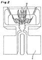
上記ラメラ構造は、粒子が上記ガス出口を通過するのを防止する(図2参照)ように、すなわち、上記開口と上記ガス出口とを互いに対して遮断するように、好適に適用される。 The lamellar structure is suitably applied to prevent particles from passing through the gas outlet (see FIG. 2), i.e. to block the opening and the gas outlet from each other.
蒸発のためのエネルギーの入力は、光学的に、すなわち不接触で行われ、チャンバの加熱は直接その中に組み込む必要が無いので、この蒸発システムは製造が簡単で、しかも原理的には、汚染の際には、容易に取り替えもできる。好適な実施形態では、本発明に係る液体蒸発器は使い捨て品として構成される。 The energy input for the evaporation takes place optically, i.e. contactlessly, and the heating of the chamber does not have to be incorporated directly into it, so this evaporation system is simple to manufacture and in principle is contaminated. In this case, it can be easily replaced. In a preferred embodiment, the liquid evaporator according to the present invention is configured as a disposable item.
上記チャネルと上記チャンバとが形成された本発明の液体蒸発器の本体は、ワンピース(継ぎ目なし)で、または複数のピースで構成することができる。好ましくは、ワンピース(継ぎ目なし)で構成される。 The main body of the liquid evaporator according to the present invention, in which the channel and the chamber are formed, can be composed of one piece (seamless) or a plurality of pieces. Preferably, it is composed of a one-piece (seamless).
上記液体蒸発器は好ましくはマイクロシステムであり、その構造はマイクロ加工技術によって製造される。 The liquid evaporator is preferably a microsystem and its structure is manufactured by microfabrication technology.
マイクロシステムにおける構造の製造は、マイクロシステム技術分野の当業者に知られている。マイクロ加工技術は、例えば、文献「Fundamentals of Microfabrication」(Marc Madou, CRC Press Boca Raton FLA 1997)または文献「Mikrosystemtechnik fuer Ingenieure [Microsystem technology for engineers] (W. Menz. J. Mohr,O. Paul, Wiley-VCH, Weinheim 2005)に記載され、説明されている。シリコン・オン・シリコン技術のより詳しい説明は、例えば、Q.-Y. Tong, U. Goesele: Semiconductor Wafer Bonding: Science and Technology; The Electrochemical Society Series, Wiley-Verlag, New York (1999)にある。グラス・オン・グラス技術については、一例として、次の文献を参照できる。J. Wie et al., Low Temperature Glass-to-Glass Wafer Bonding, IEEE Transactions on advanced packaging, Vol. 26, No. 3, 2003, pages 289-294; およびDuck-Jung Lee et al., Glass-to-Glass Anodic Bonding for High Vacuum Packaging of Microelectronics and its Stability, MEMS 2000, The Thirteenth Annual International Conference on Micro Electro Mechanical Systems, 23-27 January 2000, pages 253-258。 The manufacture of structures in microsystems is known to those skilled in the microsystem art. Microfabrication techniques are described, for example, in the document “Fundamentals of Microfabrication” (Marc Madou, CRC Press Boca Raton FLA 1997) or in the document “Mikrosystemtechnik fuer Ingenieure [Microsystem technology for engineers] (W. Menz. J. Mohr, O. Paul, Wiley). -VCH, Weinheim 2005) For a more detailed description of silicon-on-silicon technology, see, for example, Q.-Y. Tong, U. Goesele: Semiconductor Wafer Bonding: Science and Technology; Located in the Society Series, Wiley-Verlag, New York (1999) For an example of glass-on-glass technology, see J. Wie et al., Low Temperature Glass-to-Glass Wafer Bonding. , IEEE Transactions on advanced packaging, Vol. 26, No. 3, 2003, pages 289-294; and Duck-Jung Lee et al., Glass-to-Glass Anodic Bonding for High Vacuum Packaging of Microelectronics and its Stability, MEMS 2000 , The Thirteenth Annual International Conference on Micro Electro Mechanical Systems, 23-27 January 2000, pages 253-258.
マイクロシステム技術は基本的に、高アスペクト比(例えば、非常に深い(〜100μm)、狭い(〜μm)トレンチ)を有し、ストラクチャリング精度(structuring accuracies)がマイクロメータ範囲にあるシリコン基板および/またはガラス基板のストラクチャリング(構築)に基づいており、ウェットケミカル、好ましくはプラズマエッチングプロセスを、熱膨張係数の点で適合化されたナトリウム含有ガラス基板(例えば、パイレックス(登録商標))と組み合わせて用いる。それらの基板は単純なエッチング構造を備え、いわゆる陽極接合により直接に気密シールで互いに接続されているか、半田合金(AuSi)として機能する薄膜Au層により接続されている。 Microsystem technology is basically a silicon substrate having a high aspect ratio (eg, very deep (˜100 μm), narrow (˜μm) trench) and structuring accuracies in the micrometer range and / or Or based on glass substrate structuring and combining a wet chemical, preferably a plasma etching process, with a sodium-containing glass substrate (eg Pyrex®) adapted in terms of thermal expansion coefficient. Use. These substrates have a simple etching structure and are directly connected to each other by a hermetic seal by so-called anodic bonding or connected by a thin film Au layer functioning as a solder alloy (AuSi).
高アスペクト比の金属構造は、厚いフォトレジスト(> 100μm)における電解成長によって同等の精度で製造することができる(UV-LIGA)。高真空蒸着およびスパッタリング、PVD法、あるいは化学気相蒸着法(CVD法)(好ましくは、プラズマで)等の薄膜技術をフォトリソグラフィー及びエッチング技術と組み合わせて用いることにより、金属配線(メタライゼーション)や親水性または疎水性表面等の機能層、および、バルブシールやダイヤフラム、加熱素子、温度センサ、圧力センサ、流量センサ等の機能素子を、完全にプロセス互換性のある技術で、これらの基板上に集積することができる。 High aspect ratio metal structures can be produced with equivalent accuracy by electrolytic growth in thick photoresist (> 100 μm) (UV-LIGA). By using thin film technology such as high vacuum deposition and sputtering, PVD method, or chemical vapor deposition (CVD method) (preferably with plasma) in combination with photolithography and etching technology, metal wiring (metallization) Functional layers, such as hydrophilic or hydrophobic surfaces, and functional elements such as valve seals, diaphragms, heating elements, temperature sensors, pressure sensors, flow sensors, etc., on these substrates with fully process compatible technology Can be integrated.
本発明の液体蒸発器の構造は、好ましくは、シリコン・オン・グラス技術で製造される。ここで、シリコンは上記本体のために使用され、グラス(ガラス)は上記透明カバーのために使用される。このコンビネーション(好ましくは陽極接合により気密に接続されている)は、特にシリコンにおいて、システムの種々の構成部材の非常に精確なストラクチャリングを可能とする(フォトエッチ技術、DRIE、コーティング)。シリコンはガラスのように化学的にも熱的にも安定しており、しかもガラスとは異なり、熱容量が小さい良好な熱伝導体(均一温度の被加熱チャンバ)であり、従来のレーザー波長に対する良好な光吸収体である。ガラス基板を通しての散逸による熱損失は低い。 The liquid evaporator structure of the present invention is preferably manufactured with silicon-on-glass technology. Here, silicon is used for the body and glass is used for the transparent cover. This combination (preferably hermetically connected by anodic bonding) allows very precise structuring of the various components of the system, especially in silicon (photoetch technology, DRIE, coating). Silicon is stable both chemically and thermally like glass, and unlike glass, it is a good thermal conductor with a small heat capacity (heated chamber at a uniform temperature) and good for conventional laser wavelengths. Light absorber. The heat loss due to dissipation through the glass substrate is low.
シリコンとガラスのコンビネーションは、チャネルのエッジ内への光エネルギーの局所的入力およびチャネルと蒸気チャンバとの熱的分離(デカップリング)を達成することを可能とする。熱的分離(デカップリング)のためには、蒸気チャンバと液体サンプルチャネルとは熱伝導性の非常に高い熱伝導体における水平および垂直方向の切り込みによって分離されているのが好ましい。熱伝導性の低い機械的安定性は、例えばガラスまたはポリマー製の透明カバーによって確保される。 The combination of silicon and glass makes it possible to achieve local input of light energy into the edge of the channel and thermal separation (decoupling) between the channel and the vapor chamber. For thermal separation (decoupling), it is preferred that the vapor chamber and the liquid sample channel are separated by horizontal and vertical cuts in a highly thermally conductive heat conductor. Mechanical stability with low thermal conductivity is ensured by a transparent cover made of, for example, glass or polymer.
本発明の液体蒸発器をポリマー材料から、例えば射出成形技術によって作ることも考えられる。好ましくは、上記本体のために複合材料、例えば、電磁波の吸収性と熱伝導性とを向上させるためにカーボン(カーボンブラック、カーボンナノチューブ)を分散したポリマーが用いられる。 It is also conceivable to make the liquid evaporator according to the invention from a polymer material, for example by injection molding techniques. Preferably, a composite material for the main body, for example, a polymer in which carbon (carbon black, carbon nanotube) is dispersed in order to improve electromagnetic wave absorption and thermal conductivity is used.
マイクロシステム技術における従来の寸法(数十〜数百μmの範囲)のおかげで、このようにして製造されたシステムは、小さいサンプル容積(nlの液体、ガス相でμl)の分析または製造のために特に適している。 Thanks to conventional dimensions in microsystem technology (ranging from tens to hundreds of μm), the system thus produced is suitable for the analysis or production of small sample volumes (nl liquid, μl in gas phase). Especially suitable for.
そのように小さいサンプル容積を蒸発させるために、高い蒸発エンタルピーを有する液体、例えば水に対してさえも、mW域にある低レーザーエネルギしか必要とされない。これらの低いレーザーエネルギは、ファイバーまたはレンズによって結合された標準的な半導体レーザー(波長領域が例えば400nm〜980nm)によって、必要な短いパルス幅(pulse durations)で供給される(例えば1msに対して1W、10msに対して100mW)。 In order to evaporate such a small sample volume, only low laser energy in the mW range is required, even for liquids with high evaporation enthalpies, such as water. These low laser energies are supplied with the required short pulse durations (eg 1 W for 1 ms) by standard semiconductor lasers (wavelength range eg 400 nm to 980 nm) coupled by fibers or lenses. 100 mW for 10 ms).
蒸発させるべきサンプル容積は好ましくは100μl未満、特に好ましくは10μl未満、さらに好ましくは、1μl未満である。 The sample volume to be evaporated is preferably less than 100 μl, particularly preferably less than 10 μl, more preferably less than 1 μl.
本発明の液体蒸発器は好ましくは、マイクロ分析システムにおけるサンプル蒸発器として適している。それ故、本発明は、本発明の液体蒸発器の使用法であって、例えば、文献「Complex MEMS: A fully integrated TOF micro mass spectrometer (Sensors and Actuators A: Physical, 138 (1) (2007), pages 22-27))」に記載されているように、マイクロ分析システム、特に、マイクロ質量分析計またはマイクロガスクロマトグラフに使用することを特徴とする使用法も提供する。 The liquid evaporator of the present invention is preferably suitable as a sample evaporator in a microanalysis system. Therefore, the present invention is a method of using the liquid evaporator of the present invention, for example, the document `` Complex MEMS: A fully integrated TOF micro mass spectrometer (Sensors and Actuators A: Physical, 138 (1) (2007), pages 22-27)) "are also provided, characterized in that they are used for microanalysis systems, in particular for use in micromass spectrometers or microgas chromatographs.
本発明の上記液体蒸発器および本発明の液体蒸発方法は以下の点を確実にする。
・液体および液体混合物の同時蒸発
・小容積の確実な蒸発(好ましくは、< 1μlであっても)
・2つのサンプルの蒸発間の無駄な時間が短いこと
・急速な蒸発により、分析中に高い時間分解能が達成できること
・代表的サンプルの蒸発
・蒸発のための低エネルギー要件
・低い設備費用
・高い蒸発エンタルピーを有する媒体に対しても適していること
・溶解固体物(蒸発残留物、沈殿物)を含む媒体に対しても適していること
・経済的オペレーション(製造および置換)
・周辺機器についての低出費
・サンプルの分析と同期可能なサンプリング(ロックイン原理 lock-in principle)
・ガス容積のドーズ量化可能性(doseability)
・噴射ガス圧の調節可能性
・同期と複数のパルスとによる平均化
・平均化すべきサンプルの統計的選択(時間ウィンドウ)
・ガス空間における平均化
・セルフクリーニング
The liquid evaporator of the present invention and the liquid evaporation method of the present invention ensure the following points.
• Simultaneous evaporation of liquid and liquid mixture • Reliable evaporation of small volumes (preferably even if <1 μl)
• Short wasted time between evaporation of two samples • Rapid evaporation can achieve high time resolution during analysis • Typical sample evaporation • Low energy requirements for evaporation • Low equipment costs • High evaporation Suitable for media with enthalpy ・ Suitable for media containing dissolved solids (evaporation residue, precipitate) ・ Economic operation (manufacturing and replacement)
・ Low cost for peripheral equipment ・ Sampling that can be synchronized with sample analysis (lock-in principle)
・ Doseability of gas volume
-Adjustability of propellant gas pressure-Synchronization and averaging with multiple pulses-Statistical selection of samples to average (time window)
・ Average in gas space ・ Self-cleaning
以下、図面を用いて、しかしそれらに限定されることなく、本発明をより詳細に説明する。 Hereinafter, the present invention will be described in more detail with reference to the drawings, but not limited thereto.
図1は本発明の液体蒸発器を上方から見た斜視図である。この液体蒸発器は、チャネル5とチャンバ9とが形成された本体6を備えている。チャネル5とチャンバ9とは開口4を介して互いにつながっている。チャネル5は開口4の領域において湾曲(curvature)10を有する。液体はチャネル5を通り開口4を経て供給される。
FIG. 1 is a perspective view of a liquid evaporator according to the present invention as viewed from above. The liquid evaporator includes a
開口4からチャンバ9への遷移部は、開口4における毛細管力のために、隣接する領域9に液体が直接流入できないように構成される。
The transition from the opening 4 to the
上記開口の領域では、液体が電磁波を照射されて、加熱される。この場合、照射は観察者の方向から(上方から)行われる。 In the region of the opening, the liquid is irradiated with electromagnetic waves and heated. In this case, irradiation is performed from the direction of the observer (from above).
照射によって液体は加熱され,その一部が蒸発する。そしてこの一部が蒸気流として開口4からチャンバ9に入る。チャンバ9の下方には加熱要素があり、これによって蒸気チャンバ9を加熱することができる(図1には示されていない。図3参照)。
The liquid is heated by irradiation, and a part of it evaporates. A portion of this enters the
蒸気チャンバ9と液体サンプル用のチャネル5とは、熱伝導性の高い本体6における水平方向の切り込み(incisions)14によって熱的に分離されている。
The
図2は図1の液体蒸発器のチャンバ9内にラメラ構造12が導入された様子を示す。ラメラ構造は、蒸気チャンバ9下方の加熱要素(図2には示されていない。図3参照。)によって、熱伝導を通じて、加熱される。
FIG. 2 shows the
図3は、図1の液体蒸発器のA−B線断面図である。図1に関連して既に説明した構成部分の他、図3には上記本体6全体にわたって広がる透明カバー2が見える。さらに、蒸気チャンバ9下方には加熱要素8が設けられている。液体への照射は、好ましくは集光レーザービーム1によって、透明カバー2を通して行われる。
FIG. 3 is a cross-sectional view of the liquid evaporator in FIG. 1 taken along line AB. In addition to the components already described in connection with FIG. 1, the transparent cover 2 that extends over the
1 電磁波
152 透明カバー
3 液体
4 開口
5 チャネル
6 本体
207 蒸気流
8 加熱要素
9 蒸気チャンバ
10 湾曲
11 横断流
2512 ラメラ構造(層状構造)
13 ガス出口
14 切り込み
16 接続部
DESCRIPTION OF SYMBOLS 1 Electromagnetic wave 152 Transparent cover 3 Liquid 4
13
Claims (10)
上記液体はチャネルを通り開口を経て供給され、上記開口は上記液体の蒸発温度より高い温度に維持された蒸気チャンバに通じており、
上記液体の少なくとも一部が蒸発して蒸気が、加熱された上記蒸気チャンバに入るよう、上記液体は上記開口の領域で電磁波によって照射される
ことを特徴とする方法。 A method for evaporating at least a portion of a liquid,
The liquid is supplied through an opening through a channel, the opening leading to a vapor chamber maintained at a temperature higher than the evaporation temperature of the liquid,
The method wherein the liquid is irradiated by electromagnetic waves in the area of the opening so that at least a portion of the liquid evaporates and vapor enters the heated vapor chamber.
加熱は集光パルスレーザービームによって行われることを特徴とする方法。 The method of claim 1, wherein
Heating is performed by a focused pulsed laser beam.
上記液体は混合物(mixture)であることを特徴とする方法。 The method according to claim 1 or 2, wherein
A method characterized in that the liquid is a mixture.
上記蒸気チャンバを加熱する手段と
を備えたことを特徴とする液体蒸発器。 A channel and a vapor chamber are formed which are connected to each other via an opening, the channel allowing liquid to be supplied through the opening and an evaporation region adjacent to the opening optionally A main body configured to be irradiated with electromagnetic waves including an opening;
Means for heating the vapor chamber.
上記蒸発領域は、使用中の電磁波に対して少なくとも部分的に透明であるカバーを備えていることを特徴とする液体蒸発器。 The liquid evaporator according to claim 4.
The liquid evaporator, wherein the evaporation region includes a cover that is at least partially transparent to electromagnetic waves in use.
上記チャネル、上記開口、および上記蒸発領域は、上記チャネルを流れる液体が、毛細管力と界面エネルギーとの少なくとも一方により上記チャネル内に残って、上記蒸気チャンバ内に自由に流入しないように構成されていることを特徴とする液体蒸発器。 The liquid evaporator according to claim 4 or 5,
The channel, the opening, and the evaporation region are configured such that liquid flowing through the channel remains in the channel due to at least one of capillary force and interface energy and does not flow freely into the vapor chamber. A liquid evaporator.
上記チャネルは上記開口の領域に湾曲を有し、この湾曲は、流れている液体中にディーン渦を生じさせることを特徴とする液体蒸発器。 The liquid evaporator according to any one of claims 4 to 6,
The liquid evaporator, wherein the channel has a curvature in the region of the opening, the curvature creating a Dean vortex in the flowing liquid.
上記蒸気チャンバにおけるガス出口と、
上記蒸気チャンバから空気を抜くための、および/または上記蒸気チャンバを洗い流すための、上記蒸気チャンバにおける接続部と、
上記蒸気チャンバを加熱する手段に熱伝導する態様で接続され、上記ガス出口を上記開口から遮断するように配置されている、上記蒸気チャンバにおけるラメラ構造と
をさらに備えたことを特徴とする液体蒸発器。 The liquid evaporator according to any one of claims 4 to 7,
A gas outlet in the steam chamber;
A connection in the steam chamber for venting air from the steam chamber and / or for flushing the steam chamber;
A liquid evaporation further comprising: a lamellar structure in the vapor chamber, connected in a thermally conductive manner to the means for heating the vapor chamber and arranged to block the gas outlet from the opening vessel.
シリコン・オン・グラス技術のマイクロシステムとして製造され、シリコンは上記本体のために使用され、グラスは上記透明カバーのために使用されていることを特徴とする液体蒸発器。 The liquid evaporator according to any one of claims 4 to 8,
A liquid evaporator manufactured as a silicon-on-glass technology microsystem, wherein silicon is used for the body and glass is used for the transparent cover.
Applications Claiming Priority (3)
| Application Number | Priority Date | Filing Date | Title |
|---|---|---|---|
| DE102010018830A DE102010018830A1 (en) | 2010-04-29 | 2010-04-29 | A liquid vaporizer |
| DE102010018830.1 | 2010-04-29 | ||
| PCT/EP2011/056593 WO2011134968A1 (en) | 2010-04-29 | 2011-04-26 | Liquid evaporator |
Publications (2)
| Publication Number | Publication Date |
|---|---|
| JP2013527443A true JP2013527443A (en) | 2013-06-27 |
| JP2013527443A5 JP2013527443A5 (en) | 2014-06-19 |
Family
ID=44359508
Family Applications (1)
| Application Number | Title | Priority Date | Filing Date |
|---|---|---|---|
| JP2013506637A Pending JP2013527443A (en) | 2010-04-29 | 2011-04-26 | Liquid evaporator |
Country Status (7)
| Country | Link |
|---|---|
| US (1) | US20130077943A1 (en) |
| EP (1) | EP2563490A1 (en) |
| JP (1) | JP2013527443A (en) |
| CN (1) | CN103108682A (en) |
| CA (1) | CA2797608A1 (en) |
| DE (1) | DE102010018830A1 (en) |
| WO (1) | WO2011134968A1 (en) |
Cited By (1)
| Publication number | Priority date | Publication date | Assignee | Title |
|---|---|---|---|---|
| CN109289948A (en) * | 2018-10-08 | 2019-02-01 | 重庆大学 | A kind of photo-thermal orientation manipulation drop migration polyplant and its application method |
Families Citing this family (9)
| Publication number | Priority date | Publication date | Assignee | Title |
|---|---|---|---|---|
| JP6103764B2 (en) * | 2013-05-14 | 2017-03-29 | 国立大学法人福井大学 | Mass analysis method and apparatus for sample solution |
| CN103543228A (en) * | 2013-10-28 | 2014-01-29 | 徐继承 | Sampling evaporator comprising atmosphere balancing device and used for low-pressure liquefied gas inspection |
| CN103529149A (en) * | 2013-10-28 | 2014-01-22 | 徐继承 | Anti-clogging sample injection evaporator for low pressure liquefied gas examination |
| CN104392883A (en) * | 2014-10-22 | 2015-03-04 | 常州博锐恒电子科技有限公司 | Solid feeding method of implantation machine |
| CN109963324B (en) | 2017-12-22 | 2023-06-02 | 华为技术有限公司 | Wireless wake-up packet sending and receiving method and device |
| CN109444248B (en) * | 2018-11-20 | 2020-10-30 | 中国地质大学(武汉) | Solution ablation sample injection analysis method based on laser |
| NL2023927B1 (en) | 2019-10-01 | 2021-06-01 | Berkin Bv | In-flow evaporator |
| CN115155077B (en) * | 2022-07-04 | 2023-08-18 | 枣庄学院 | Multi-component liquid micro-evaporation device |
| US11938414B1 (en) * | 2022-10-04 | 2024-03-26 | Honeywell Federal Manufacturing & Technologies, Llc | Microfluidic film evaporation with femtosecond laser-patterned surface |
Citations (4)
| Publication number | Priority date | Publication date | Assignee | Title |
|---|---|---|---|---|
| WO1999000824A1 (en) * | 1997-06-26 | 1999-01-07 | Iowa State University Research Foundation, Inc. | Laser vaporization/ionization interface for coupling microscale separation techniques with mass spectrometry |
| JP2001070841A (en) * | 1999-09-06 | 2001-03-21 | Hitachi Ltd | Atomizer and analyzer using the same |
| JP2003035699A (en) * | 2001-07-19 | 2003-02-07 | Kitakyushu Foundation For The Advancement Of Industry Science & Technology | Supersonic molecular jet spectroscopic analysis method and apparatus |
| JP2009069088A (en) * | 2007-09-18 | 2009-04-02 | Fujitaro Imasaka | Method for introducing pulse sample based on laser evaporation method |
Family Cites Families (11)
| Publication number | Priority date | Publication date | Assignee | Title |
|---|---|---|---|---|
| US6653626B2 (en) | 1994-07-11 | 2003-11-25 | Agilent Technologies, Inc. | Ion sampling for APPI mass spectrometry |
| FR2753533B1 (en) * | 1996-09-17 | 1998-10-09 | Commissariat Energie Atomique | METHOD AND DEVICE FOR CHARACTERIZING A MODIFICATION OVER TIME OF THE CONDENSATION STATE OF DROPLETS ON A TARGET |
| DE10049856A1 (en) * | 2000-10-09 | 2002-03-07 | Siemens Ag | Device for continuously vaporizing small amounts of liquid in heated vaporizing chamber comprises capillary which introduces liquid slowly into vaporizing chamber, and device for exciting free end of capillary |
| US20040099310A1 (en) * | 2001-01-05 | 2004-05-27 | Per Andersson | Microfluidic device |
| DE10242797A1 (en) * | 2002-09-14 | 2004-03-25 | Degussa Ag | Causing phase change in materials, e.g. vaporization of metal halogenides, moves them through reactor under electromagnetic irradiation |
| UA79331C2 (en) * | 2002-11-08 | 2007-06-11 | Oleksandr V Vladimirov | Method for manufacturing gas-discharge electron lamps (variants) |
| DE10335451A1 (en) | 2003-08-02 | 2005-03-10 | Bayer Materialscience Ag | Method for removing volatile compounds from mixtures by means of micro-evaporator |
| WO2007109214A2 (en) | 2006-03-20 | 2007-09-27 | Rasirc | Vaporizer for delivery of low vapor pressure gasses |
| EP1959476A1 (en) | 2007-02-19 | 2008-08-20 | Technische Universität Hamburg-Harburg | Mass spectrometer |
| ITRM20070105A1 (en) * | 2007-02-26 | 2008-08-27 | Univ Roma | WATER DISTILLATION SYSTEM FOR INJECTABLE USE |
| US8586348B2 (en) * | 2010-09-22 | 2013-11-19 | California Institute Of Technology | Lateral flow microfluidic assaying device and related method |
-
2010
- 2010-04-29 DE DE102010018830A patent/DE102010018830A1/en not_active Withdrawn
-
2011
- 2011-04-26 CA CA2797608A patent/CA2797608A1/en active Pending
- 2011-04-26 EP EP11717251A patent/EP2563490A1/en not_active Withdrawn
- 2011-04-26 WO PCT/EP2011/056593 patent/WO2011134968A1/en active Application Filing
- 2011-04-26 CN CN2011800324679A patent/CN103108682A/en active Pending
- 2011-04-26 JP JP2013506637A patent/JP2013527443A/en active Pending
- 2011-04-26 US US13/643,514 patent/US20130077943A1/en not_active Abandoned
Patent Citations (4)
| Publication number | Priority date | Publication date | Assignee | Title |
|---|---|---|---|---|
| WO1999000824A1 (en) * | 1997-06-26 | 1999-01-07 | Iowa State University Research Foundation, Inc. | Laser vaporization/ionization interface for coupling microscale separation techniques with mass spectrometry |
| JP2001070841A (en) * | 1999-09-06 | 2001-03-21 | Hitachi Ltd | Atomizer and analyzer using the same |
| JP2003035699A (en) * | 2001-07-19 | 2003-02-07 | Kitakyushu Foundation For The Advancement Of Industry Science & Technology | Supersonic molecular jet spectroscopic analysis method and apparatus |
| JP2009069088A (en) * | 2007-09-18 | 2009-04-02 | Fujitaro Imasaka | Method for introducing pulse sample based on laser evaporation method |
Cited By (1)
| Publication number | Priority date | Publication date | Assignee | Title |
|---|---|---|---|---|
| CN109289948A (en) * | 2018-10-08 | 2019-02-01 | 重庆大学 | A kind of photo-thermal orientation manipulation drop migration polyplant and its application method |
Also Published As
| Publication number | Publication date |
|---|---|
| EP2563490A1 (en) | 2013-03-06 |
| CN103108682A (en) | 2013-05-15 |
| WO2011134968A1 (en) | 2011-11-03 |
| CA2797608A1 (en) | 2011-11-03 |
| DE102010018830A1 (en) | 2011-11-03 |
| US20130077943A1 (en) | 2013-03-28 |
Similar Documents
| Publication | Publication Date | Title |
|---|---|---|
| JP2013527443A (en) | Liquid evaporator | |
| McNamara et al. | On-chip vacuum generated by a micromachined Knudsen pump | |
| Akbar et al. | GC-on-chip: integrated column and photoionization detector | |
| Chen et al. | Optofluidic guiding, valving, switching and mixing based on plasmonic heating in a random gold nanoisland substrate | |
| US20090212204A1 (en) | Channel Cell System | |
| IL181140A (en) | Ion mobility spectrometer | |
| Saarela et al. | Glass microfabricated nebulizer chip for mass spectrometry | |
| US20120207625A1 (en) | Thermally driven knudsen pump | |
| Qin et al. | iGC2: An architecture for micro gas chromatographs utilizing integrated bi-directional pumps and multi-stage preconcentrators | |
| CN102644049A (en) | Micro-flow driving method based on TiO2 nano-film wettability | |
| JP2009534629A (en) | 3-wafer channel structure for fluid analyzer | |
| US7367781B2 (en) | Packaged micromachined device such as a vacuum micropump, device having a micromachined sealed electrical interconnect and device having a suspended micromachined bonding pad | |
| Wilson et al. | Investigation of volatile liquid surfaces by synchrotron x-ray spectroscopy of liquid microjets | |
| Phan et al. | Fabrication and testing of a miniature flat evaporator loop heat pipe with polydimethylsiloxane and molding | |
| Maurice et al. | Wafer-level vapor cells filled with laser-actuated hermetic seals for integrated atomic devices | |
| JP2022502661A (en) | Integrated micro photoionization detector with ultra-thin UV transmission window | |
| Byambadorj et al. | A monolithic Si-micromachined four-stage Knudsen pump for µGC applications | |
| CA2991198C (en) | Method and system for producing laser ablation plumes without ablation recoil products | |
| Priest et al. | Structure-induced spreading of liquid in micropillar arrays | |
| US20070145262A1 (en) | On-chip electrochemical flow cell | |
| Grzebyk et al. | Pressure control system for vacuum MEMS | |
| EP2326420A1 (en) | Concentrator and locator device of a solute and method for concentrating and locating a solute | |
| US7703313B2 (en) | Conformal film micro-channels for a fluidic micro analyzer | |
| Dziurdzia et al. | A ceramic mini system for the detection of hydrocarbon radicals | |
| Southard et al. | Liquid chromatography-mass spectrometry interface for detection of extraterrestrial organics |
Legal Events
| Date | Code | Title | Description |
|---|---|---|---|
| A521 | Request for written amendment filed |
Free format text: JAPANESE INTERMEDIATE CODE: A523 Effective date: 20140425 |
|
| A621 | Written request for application examination |
Free format text: JAPANESE INTERMEDIATE CODE: A621 Effective date: 20140425 |
|
| A131 | Notification of reasons for refusal |
Free format text: JAPANESE INTERMEDIATE CODE: A131 Effective date: 20141125 |
|
| A977 | Report on retrieval |
Free format text: JAPANESE INTERMEDIATE CODE: A971007 Effective date: 20141126 |
|
| A601 | Written request for extension of time |
Free format text: JAPANESE INTERMEDIATE CODE: A601 Effective date: 20150224 |
|
| A521 | Request for written amendment filed |
Free format text: JAPANESE INTERMEDIATE CODE: A523 Effective date: 20150318 |
|
| RD03 | Notification of appointment of power of attorney |
Free format text: JAPANESE INTERMEDIATE CODE: A7423 Effective date: 20150421 |
|
| A521 | Request for written amendment filed |
Free format text: JAPANESE INTERMEDIATE CODE: A821 Effective date: 20150421 |
|
| RD04 | Notification of resignation of power of attorney |
Free format text: JAPANESE INTERMEDIATE CODE: A7424 Effective date: 20150513 |
|
| A02 | Decision of refusal |
Free format text: JAPANESE INTERMEDIATE CODE: A02 Effective date: 20150724 |