JP2013526358A - Storeable hot water or steam delivery device - Google Patents
Storeable hot water or steam delivery device Download PDFInfo
- Publication number
- JP2013526358A JP2013526358A JP2013510632A JP2013510632A JP2013526358A JP 2013526358 A JP2013526358 A JP 2013526358A JP 2013510632 A JP2013510632 A JP 2013510632A JP 2013510632 A JP2013510632 A JP 2013510632A JP 2013526358 A JP2013526358 A JP 2013526358A
- Authority
- JP
- Japan
- Prior art keywords
- beverage preparation
- preparation machine
- generator
- outlet
- machine according
- Prior art date
- Legal status (The legal status is an assumption and is not a legal conclusion. Google has not performed a legal analysis and makes no representation as to the accuracy of the status listed.)
- Ceased
Links
Images


Classifications
-
- A—HUMAN NECESSITIES
- A47—FURNITURE; DOMESTIC ARTICLES OR APPLIANCES; COFFEE MILLS; SPICE MILLS; SUCTION CLEANERS IN GENERAL
- A47J—KITCHEN EQUIPMENT; COFFEE MILLS; SPICE MILLS; APPARATUS FOR MAKING BEVERAGES
- A47J31/00—Apparatus for making beverages
- A47J31/44—Parts or details or accessories of beverage-making apparatus
- A47J31/4489—Steam nozzles, e.g. for introducing into a milk container to heat and foam milk
-
- A—HUMAN NECESSITIES
- A47—FURNITURE; DOMESTIC ARTICLES OR APPLIANCES; COFFEE MILLS; SPICE MILLS; SUCTION CLEANERS IN GENERAL
- A47J—KITCHEN EQUIPMENT; COFFEE MILLS; SPICE MILLS; APPARATUS FOR MAKING BEVERAGES
- A47J31/00—Apparatus for making beverages
- A47J31/44—Parts or details or accessories of beverage-making apparatus
Landscapes
- Engineering & Computer Science (AREA)
- Food Science & Technology (AREA)
- Apparatus For Making Beverages (AREA)
Abstract
飲料調製機(1)は、開口(41)を備えた本体(40)と、移動可能な排出口(31)を備える湯及び/又は蒸気発生器とを有する。発生器及び排出口は、排出口を経て湯及び/又は蒸気を配送する為の操作上の構成と、内部で発生器の排出口(31)が本体の開口(41)に移動されて収容される収納機器構成とを有する。
【選択図】 図11-3 概略図The beverage preparation machine (1) has a body (40) with an opening (41) and a hot water and / or steam generator with a movable outlet (31). The generator and outlet are housed in an operational configuration for delivering hot water and / or steam through the outlet, and the generator outlet (31) is moved to the opening (41) of the body inside. Storage device configuration.
[Selection] Figure 11-3 Schematic diagram
Description
本発明の分野は、湯及び/又は蒸気配送装置を有する飲料を調製する為の機械に関する。 The field of the invention relates to machines for preparing beverages having hot water and / or steam delivery devices.
特に、本発明の分野は、特にカプセル内部に供給された風味付き原料を通して流体を循環することにより、飲料を調製する為、湯及び/又は蒸気用排出口を有する機械に関する。 In particular, the field of the invention relates to machines with hot and / or steam outlets for preparing beverages, in particular by circulating fluids through flavored ingredients supplied inside the capsule.
本発明の説明で、「飲料」は、ティー、ホットチョコレート、コールドチョコレート、ミルク、スープ、ベビーフード等のような如何なる液体食物をも含むことを意味する。「カプセル」は、材料の同封パッケージ内部の予め小分けされた飲料原料、特に、原料を含む堅いカートリッジ又は柔らかいポッドを含む、如何なる形状及び構造の、気密パッケージ(例えば、プラスチック、アルミニウム、リサイクル可能な更に/又は生物分解可能なパッケージ)を含むことを意味する。 In the description of the present invention, “beverage” is meant to include any liquid food such as tea, hot chocolate, cold chocolate, milk, soup, baby food and the like. A “capsule” can be any shape and structure of a hermetic package (eg, plastic, aluminum, recyclable further, including a pre-divided beverage ingredient within an enclosed package of ingredients, in particular a rigid cartridge or soft pod containing the ingredient. (Or biodegradable package).
ミルク含有飲料、例えば、ミルク含有コーヒー、ティー、チョコレートドリンクのような飲料を製造する為の機械は、技術的に知られている。 Machines for producing milk-containing beverages, for example beverages such as milk-containing coffee, tea, chocolate drinks, are known in the art.
技術的に知られているように、そのような飲料を製造するために、湯及び/又は蒸気を製造する為のヒータを経て水が通され、使用者のカップやマグの中へと対応パイプを経て注出されてもよい。たとえば、そのような湯の注出は、ティーを調製する為に使用可能である。熱い蒸気の注出は、ミルクの泡立て処理(すなわち、ミルクを含む容器内に熱い蒸気を注入することにより、例えば、伝統的な「バリスタ」ミルク泡立て技術を適用することにより、特に、注入された蒸気に関して容器を動かす間にミルクが加熱され、注入された蒸気の影響下で乳状化されること)に含まれる場合がある。 As is known in the art, in order to produce such a beverage, water is passed through a heater for producing hot water and / or steam and the corresponding pipe into the user's cup or mug. It may be dispensed via. For example, such pouring of hot water can be used to prepare tea. Hot steam pouring was infused by milk frothing treatment (ie, by injecting hot steam into a container containing milk, for example, by applying traditional “barista” milk frothing technology, in particular. The milk is heated while moving the container with respect to the steam and may be included in the milking under the influence of the injected steam.
そのような湯及び/又は蒸気注出用パイプは、通常、風味付き飲料機、特にコーヒー機、例えば、カプチーノやカフェラテの調製の為に、組み込まれる場合がある。 Such hot and / or steam extraction pipes are usually incorporated for the preparation of flavored beverage machines, in particular coffee machines, such as cappuccino and latte.
例えば、EP1764014及びEP1900312は、湯及び/又は蒸気を注出する為の排出口を備えた水循環路を有するコーヒー機を開示する。EP097481は、蒸気用排出口及び湯用排出口を有する他の飲料調製機を開示する。 For example, EP 1764014 and EP 1900312 disclose coffee machines having a water circuit with an outlet for pouring hot water and / or steam. EP 097481 discloses another beverage preparation machine having a steam outlet and a hot water outlet.
DE19611450,EP0607759、EP1501398,EP1776905,WO2007/09577は、ミルクカップの中への漬浸の為の空気−蒸気用ランスを開示する。 DE19611450, EP06077759, EP1501398, EP1776905, WO2007 / 09557 disclose an air-steam lance for soaking in a milk cup.
WO2008/034708は、同一の使用者のカップの中に流体を配送する為の位置にもたらすことが可能なコーヒー用排出口と蒸気用排出口とを有するコーヒー機を開示するが、コーヒー用排出口は、蒸気用排出口に対して水平に移動可能になっている。 WO 2008/034708 discloses a coffee machine having a coffee outlet and a steam outlet that can be brought into position for delivering fluid into the same user's cup, but the coffee outlet Can move horizontally with respect to the steam outlet.
US6,293,187は、蒸気用パイプを開示し、この蒸気用パイプは、中に含まれたミルクを泡立たせる為にカップ内に、その排出口を自動的に移動させる為に垂直に変位可能になっている。蒸気用パイプは、排出口を備えた交換可能なノズル部材を有し、それが、ミルクと接触するようになる。 US 6,293,187 discloses a steam pipe, which can be displaced vertically to automatically move its outlet into the cup for frothing the milk contained therein. It has become. The steam pipe has a replaceable nozzle member with an outlet, which comes into contact with milk.
湯及び/又は蒸気発生循環路は、使用中、水から堆積される湯垢を蓄積する傾向にある。この湯垢が除去されないと、循環路は詰まり、これ以上、使えなくなる。そのような循環路を有する機械を、洗浄及び/又は湯垢除去処理により維持することが知られているが、これらの処理の間、洗浄/湯垢除去流体、例えば、湯垢除去処理剤を運ぶ水が循環路を通って循環され、通常、その循環路の排出口の下に置かれるカップ、マグ又は他のサービス用の容器に集められる。 Hot water and / or steam generation circuits tend to accumulate scale accumulated from water during use. If this scale is not removed, the circuit is clogged and can no longer be used. It is known to maintain machines having such a circuit by washing and / or descaling processes, but during these processes, water carrying a scrubbing / scaling fluid, such as descaling agent, is used. It is circulated through the circuit and is usually collected in a cup, mug or other service container that is placed under the circuit outlet.
依然として、特に安全なメンテナンス装置を備えた簡単な湯及び/又は蒸気配送装置を提供することが必要である。 There remains a need to provide a simple hot water and / or steam delivery device with a particularly safe maintenance device.
そのため、本発明は、飲料を調製する為の機械に関する。この機械は、開口を備えた本体と、移動可能な排出口を備える湯及び/又は蒸気発生器とを含む。上記発生器及び排出口は、上記排出口を経て上記湯及び/又は蒸気を配送する為の操作機器構成を有する。 The present invention therefore relates to a machine for preparing a beverage. The machine includes a body with an opening and a hot water and / or steam generator with a movable outlet. The generator and the outlet have an operating device configuration for delivering the hot water and / or steam through the outlet.
上記本体は、その機械のハウジング又はその一部を形成してもよい。通常、上記機械は、そのような湯及び/又は蒸気を上記発生器の排出口から使用者のカップ又はマグの中に配送する為の湯及び/又は蒸気配送領域を有する。上記カップ又はマグは、普通、上記本体に対して外部にある配送領域内に置かれてもよく、更に/或いは、上記カップ又はマグ内に含まれるミルクを例えば泡立たせる為に、手に持たれ、手動で湯及び/又は蒸気用排出口に対して移動されてもよい。 The body may form a housing or part of the machine. Typically, the machine has a hot and / or steam delivery area for delivering such hot water and / or steam from the generator outlet into the user's cup or mug. The cup or mug may be placed in a delivery area that is usually external to the body and / or held in the hand, for example to foam the milk contained in the cup or mug. It may be manually moved relative to the hot water and / or steam outlet.
本発明によると、発生器は、収納機器構成を有し、その中で、発生器の排出口が本体の開口内に移動されて収容される。 According to the present invention, the generator has a storage device configuration, in which the outlet of the generator is moved into the opening of the main body and stored.
このため、上記機械は、移動可能な排出口を当該機械の本体の開口の中に移動させることにより、湯及び/又は蒸気発生器の上記移動可能な排出口を収納、通常は固定する為の簡単な機器構成を有する。したがって、排出口の移動の自由度が減じられ、更に/又は、その排出口を経て配送される如何なる流体も、その開口を経て本体内に閉じ込められる。 For this reason, the machine accommodates, usually fixes, the movable outlet of hot water and / or steam generator by moving the movable outlet into the opening of the machine body. It has a simple equipment configuration. Accordingly, the degree of freedom of movement of the outlet is reduced and / or any fluid delivered through the outlet is confined within the body through the opening.
そのような収納する機器構成は、その機械又は少なくとも発生器が無効であるとき、例えば、収納されているか、単に飲料調製処理に使用されていないとき、更に/又は、その発生器が洗浄処理、特に湯垢除去処理にあるとき、制御されない流体の発生器の排出口からの射出を防止し、そのような流体を特に上記機械の本体内に閉じ込めるのに適している。 Such storage equipment configuration may be used when the machine or at least the generator is disabled, for example, when stored or not simply used in a beverage preparation process, and / or when the generator is washed. Especially during the descaling process, it is suitable for preventing uncontrolled injection of fluid from the generator outlet and confining such fluid especially in the machine body.
上記本体は、廃液を集める為にリザーバを備えてもよいことになる。リザーバは、発生器の開口を経て配送される流体を集める為に使用されてもよい。そのような流体は、発生器の排出口から配送されてもよく、洗浄処理中は洗浄流体、及び/又は、先の湯及び/又は蒸気配送処理から生じる流滴を含んでもよい。 The main body may include a reservoir for collecting waste liquid. The reservoir may be used to collect fluid that is delivered through the opening of the generator. Such fluid may be delivered from the outlet of the generator and may include cleaning fluid during the cleaning process and / or droplets resulting from the previous hot water and / or steam delivery process.
上記本体は、通常、空にするために、更に/又は、リザーバを洗浄するために、取り外し可能であってもよい。上記機械は、例えば、ヒータ、制御ユニットのような能動的な部品を含む主要本体と、湯及び/又は蒸気発生器の排出口を収容する為の開口を含む取り外し可能な本体のような補助本体とを有してもよい。後者の本体は、機械的に主要な本体に連結されてもよく、例えば、修理の為に使用者により、そこから分離可能であってもよい。 The body may typically be removable to empty and / or to clean the reservoir. The machine includes, for example, a main body including active components such as heaters and control units, and an auxiliary body such as a removable body including an opening for receiving a hot water and / or steam generator outlet. You may have. The latter body may be mechanically coupled to the main body and may be separable therefrom by the user for repair, for example.
一実施形態において、発生器の排出口を収容する為の本体により、飲料注出領域の範囲が決まる。上記本体は、使用者のカップ及び/又は使用者のマグを支える為の上面を備えてもよく、その中に湯及び/又は蒸気が配送される。上記本体の上面は、グリッド又は廃液リザーバの中に通じる一つ以上のチャネルのような廃液を排出するための装置により形成されてもよい。このため、本体は、飲料調製機の流滴トレイ装置を形成してもよい。 In one embodiment, the body for containing the generator outlet defines the extent of the beverage dispensing area. The body may include a top surface for supporting the user's cup and / or the user's mug into which hot water and / or steam is delivered. The top surface of the body may be formed by a device for draining waste liquid, such as a grid or one or more channels leading into a waste reservoir. For this reason, the main body may form a drip tray device of a beverage preparation machine.
上記発生器の排出口を収容する為の本体は、そのような飲料調製機から突き出ているプラットフォームを形成してもよい。上記排出口の為の開口は、本体の上面に配置されてもよく、特に、その上面の周辺部に配置されてもよい。プラットフォームの中央部は、その上に使用者のカップ又は使用者のマグを置く為に役立ててもよい。 The body for housing the generator outlet may form a platform protruding from such a beverage preparation machine. The opening for the discharge port may be disposed on the upper surface of the main body, and in particular, may be disposed on the periphery of the upper surface. The central portion of the platform may serve to place a user's cup or user's mug on it.
普通、上記湯及び/又は蒸気発生器は、使用者が移動可能な管を備えてもよく、これが、発生器の排出口を支える。上記管の動作は、その排出口の動作を問題なく引き起こすであろう。上記管は、使用者により手動で、操作機器構成の中に、更に、収納機器構成の中に移動可能であってもよい。上記管の動作は、また、モータを使用することにより、自動的であってもよい。上記管は、収納機器構成内で、ほぼ直立であってもよい。上記管は、縦に移動可能であり、任意で伸縮自在に移動可能であり、管の排出口を収容する為に本体の中に特に縦に移動可能である。上記管は、旋回可能であり、普通、上記機械の本体の外側に或いは上記機械のハウジングに、旋回できるように装着可能である。上記管は、旋回されてもよく、更に/又は、湯及び/又は蒸気を配送する為に、収納位置から、その操作機器構成の中へと縦に移動されてもよい。 Typically, the hot water and / or steam generator may be provided with a tube that can be moved by the user, which supports the outlet of the generator. The operation of the tube will cause its outlet operation without problems. The tube may be manually movable by the user into the operating device configuration and further into the storage device configuration. The operation of the tube may also be automatic by using a motor. The tube may be substantially upright in the storage equipment configuration. The tube is movable vertically, optionally telescopically movable, and particularly vertically movable in the body to accommodate the outlet of the tube. The tube is pivotable and is usually mounted so that it can pivot on the outside of the machine body or on the machine housing. The tube may be swiveled and / or moved vertically from the stowed position into its operating equipment configuration to deliver hot water and / or steam.
上記水及び/又は蒸気発生器は、洗浄構成機器、例えば、湯垢除去機器構成を有し、その中で、発生器の排出口は、本体の開口内に移動され、収容される。そのような湯垢除去機器構成のような洗浄機器構成において、発生器の排出口の位置、存在する時には管の位置は、収納機器構成におけるものと同一でもよい。洗浄機器構成は、通常、湯垢除去流体のような洗浄流体を循環させる為に、発生器の排出口及び本体の開口を経て、発生器から本体の中に配置されている。安全性及び/又は適切な操作を高める為に、上記機械は、発生器の排出口が本体の開口から離れているとき、洗浄(例えば湯垢除去)を防止する為に、配置された(例えばプログラムされた)制御ユニットを含んでもよい。たとえば、上記機械は、発生器の排出口の位置を検出する為のセンサを、少なくとも収納及び/又は洗浄機器構成内に含む。 The water and / or steam generator has a cleaning component, for example, a descaling device configuration, in which the outlet of the generator is moved and housed within the opening of the body. In a cleaning device configuration such as such a scale removal device configuration, the location of the generator outlet and, if present, the location of the tube may be the same as in the storage device configuration. The cleaning equipment configuration is typically placed from the generator into the body through the generator outlet and body opening to circulate a cleaning fluid such as scale removal fluid. In order to increase safety and / or proper operation, the machine is arranged (eg programmed) to prevent cleaning (eg descaling) when the generator outlet is away from the body opening. Control unit). For example, the machine includes a sensor for detecting the position of the generator outlet, at least in the storage and / or cleaning equipment configuration.
また、上記制御ユニットは、発生器が洗浄機器構成及び/又は収納機器構成内にあるとき、発生器の排出口を経た湯及び/又は蒸気の配送を含む飲料調製を防止する為に設けられてもよい。 The control unit is also provided to prevent beverage preparation including hot water and / or steam delivery through the generator outlet when the generator is in the cleaning equipment configuration and / or storage equipment configuration. Also good.
上記飲料調製機は、風味付き原料、特に、風味付き原料を含むカプセルを収容し、風味付き飲料を形成する為に上記風味付き原料を通して水を循環する為のモジュールのような、風味付き飲料調製モジュールを更に備えてもよい。たとえば、上記機械は、コーヒー、ティー又はスープ機である。 The beverage preparation machine contains flavored ingredients, in particular capsules containing flavored ingredients, and a flavored beverage preparation, such as a module for circulating water through the flavored ingredients to form a flavored beverage. A module may be further provided. For example, the machine is a coffee, tea or soup machine.
上記機械は、調製される飲料の風味付き原料(例えば、挽かれたコーヒー、ティー又はチョコレート又はカカオ又はミルク粉末)を含むカプセルに湯又は冷水或いは他の液体を通すことにより淹出ユニットの内部で飲料を調製する為に配置されてもよい。 The machine is used inside the brewing unit by passing hot or cold water or other liquid through capsules containing flavored ingredients of the beverage to be prepared (eg ground coffee, tea or chocolate or cacao or milk powder). It may be arranged to prepare a beverage.
以下、本発明に従う飲料機の実施形態を例示する概略図1〜図3を参照して、本発明を説明する。
機械1は、電気コード9を経て、通常は送電線により、電力が供給可能である。
The
機械1は、ハウジング2により覆われた内部飲料調製モジュールを有する。
The
飲料調製モジュールは、風味付き原料、特に、カプセル内部で、そのようなモジュール配送された原料のような予め小分けされた原料を保持し、飲料を形成する為に、そこを通って液体を循環する為に配置されている。 Beverage preparation modules hold flavored ingredients, particularly pre-divided ingredients such as those delivered by the module, inside the capsule and circulate liquid therethrough to form a beverage It is arranged for the purpose.
液体、例えば、水は、収納され、タンク3から飲料調製モジュールに供給される。飲料は、形成の際、排出口4を経て、注出領域5,40、例えば、使用者のカップやマグを保持する為の支持体に注出可能である。注出領域は、ルンゴや特別に大きい飲料に対する大きいカップやマグの為に下部の第2のカップ支持体40に出入りを許す為に、下の排出口4から離れて移動可能な第1のカップ支持体5,例えば、エスプレッソカップの為の支持体を含んでもよい。下のカップ支持体40は、機械1のベース8に連結されてもよい。適した移動可能なカップ支持体は、例えば、EP1867260およびWO2009/074557に開示され、その内容は、参考の為に本願に組み込まれる。
Liquid, for example water, is stored and supplied from the
また、機械1は、例えば、泡立てられたミルク及び/又はティーの調製の為に、管30の開口31を経て、そのような蒸気及び/又は湯を注出する為の蒸気及び/又は湯発生器を含む。
The
飲料調製モジュールに隣接して、機械1は、たとえばカプセル内部に含まれた、使用済み風味付き原料(例えば、淹出の際のティーや挽かれたコーヒー)の為のコレクタ6を有してもよい。コレクタ6は、飲料調製モジュールの下に置かれ、飲料調製の際、例えば重力によりコレクタ6に排出される使用済みの風味付き原料を集めてもよい。適したコレクタは、例えば、WO2009/074559及びWO2009/135869に開示され、これらは、参考の為に本願に組み込まれる。
Adjacent to the beverage preparation module, the
機械1は、例えばカプセル内部の原料をモジュールの中に装填及び/又はモジュールからそのような原料を排出する為の移送位置と、原料を通して液体を循環する為の循環位置との間を移動可能なハンドル10を有する。
The
通常、ハンドル10は、飲料調製モジュールの、淹出ユニットのような原料チャンバを備えた原料ホルダを、風味付き原料をホルダの中に挿入及び/又はそこからこの原料を排出する為の移送位置(図示せず)から、更に、飲料を形成する為に原料ホルダ内の原料を通じて液体を循環させる為の循環位置から作動させる。通常、原料ホルダ、例えば、淹出ユニットは、相対的に移動可能な2つの部品を有し、これらは、原料ホルダを開く為に移送位置へと遠くに動かされ、循環位置へと原料ホルダを閉じる為に一緒に動かされる。循環位置(図示せず)において、原料ホルダは、しっかりと風味付き原料を囲み、原料を通って液体を適切に案内することを確実にする。
Typically, the
循環位置において、ハンドル10は、機械1の最上面2aに載せてあるか、動かずにあってもよい。特にハンドル10は、ハウジング2と同じ高さでもよい。
In the circulating position, the
図1に示されるように、ハンドル10は、人間工学的な理由、すなわち、ハンドル10が移送位置から循環位置まで移動されるとき、使用者の手にとって接触面12の都合の良い向きによりハンドル10上に手動で力を加えることを容易にするため、末端11で僅かに湾曲または曲げられた直線状の棒のように概略形成された単一のアームレバーでもよい。循環位置において、末端11を備えたハンドル10は、ハウジング2と同じ高さにあり、ハンドル2は、例えば、ハウジング2の表面の洗浄を容易にするため、対応した形状を有する。
As shown in FIG. 1, the
このため、ハンドル10は、人の手により接触されて駆動されるように駆動部12が配置され、ハンドルを、例えば、カプセル内に封入された風味付き原料が、例えば通路7を経て飲料調製モジュールの中に挿入される移送位置と、風味付き原料が飲料調製モジュール内に収容されて飲料を形成する為にそこから液体が循環可能な循環位置との間を移動させる。
For this reason, the
図1は、移送位置と循環位置の間の中間位置にあるハンドル10を示す。移送位置において、ハンドル10は、通路7を全体的にむきだしにし、例えばカプセル内部の風味付き原料を飲料調製モジュールの中に挿入することができる。
FIG. 1 shows the
通路7は、風味付き原料の重力により飲料調製モジュールの中に挿入する為に配置可能であり、ハンドル10が移送位置にあるとき、例えばカプセル内部の風味付き原料の通路7への手動挿入と、特に使用者が同じ手を使用できる手動作動ハンドル10との間の調整を容易にするため、駆動部分12は、通路7のほぼ上方及び/又は通路7に隣接して置かれている。
The
さらに、機械1は、飲料調製モジュール内の風味付き原料を通して液体の循環を始める為のユーザーインターフェース29を含む。
In addition, the
飲料調製モジュールは、通常、以下の構成要素の一つ以上を含む。 A beverage preparation module typically includes one or more of the following components.
a)この飲料の風味付き原料、特にカプセル内部に供給された予め小分けされた原料を受ける為の、更に、入ってくる水のような液体の流れを上記原料を通して飲料用排出口4まで案内する為の飲料ユニットのような原料ホルダ、
b)原料ホルダまで供給される上記液体の流れを加熱する為のサーモブロックのようなインラインヒータ、
c)この液体をインラインヒータを通して送る為のポンプ、
d)液体のタンク3のような液体源から、飲料用排出口4まで、この液体を案内する為の一つ以上の流体接続部材、
e)インターフェースを介して使用者からの指示を受ける為の、更に、上記インラインヒータ及び上記ポンプを制御する為の、特に印刷回路基板(PCB)を備える電気制御ユニット、
f)上記原料ホルダ、上記インラインヒータ、上記ポンプ、液体リザーバ3,原料コレクタ6,この液体の流れ、この液体の圧力、この液体の温度の特定から選択された少なくとも一つの操作上の特性を感知する為の、更に、そのような特性を上記制御ユニットに通信する為の一つ以上の電気センサ
ヒータは、サーモブロック又はオン・デマンドヒータ(ODH)、例えば、EP1253844、EP1380243,EP1809151に開示されたODH型でもよい。適した飲料ユニット及びカプセル管理の実施例は、例えば、WO2005/004683、WO2007/135136、WO2009/043630に開示されており、これらは、本願に参考の為に組み込まれる。適した飲料調製モジュールは、例えばWO2009/074550、WO2009/130099に開示されており、これらは、本願に参考の為に組み込まれる。
a) In order to receive the flavored ingredients of this beverage, especially the pre-divided ingredients supplied inside the capsule, the flow of liquid such as incoming water is guided to the
b) An in-line heater such as a thermo block for heating the flow of the liquid supplied to the raw material holder,
c) A pump for sending this liquid through an in-line heater,
d) one or more fluid connection members for guiding the liquid from a liquid source such as a
e) an electrical control unit with a printed circuit board (PCB) in particular for receiving instructions from the user via the interface and for controlling the in-line heater and the pump;
f) Sensing at least one operational characteristic selected from identifying the raw material holder, the in-line heater, the pump, the
ハンドル10とユーザーインターフェース20は、図2に例示されているように、ハンドル10を循環位置へと駆動する際、ハンドル10の駆動部12に人の手がまだ接触している間に、その手によりユーザーインターフェース20を操作できるように配置可能である。
As illustrated in FIG. 2, the
たとえば、駆動部12は、人差し指、中指、薬指、小指のうちの一つ以上により接触され作動可能であり、ユーザーインターフェース20は、一本の指及び/又は複数の指がハンドル10に触れている間、例えば、ハンドル10を、その循環位置へと移動させた後、ハンドル10から手を離して移動させることなく、手の指により操作可能である。便利のため、駆動部12は、手で駆動される為に特に適合された断面形状又は表面を有してもよく、例えば、駆動部12の表面は、表面構造又は構成物のような手段、特に手に摩擦を与えるアンチスキッド表面を含んでもよい。
For example, the
駆動部12は、ハンドル10を駆動する為に人の手により押されるように配置可能である。ユーザーインターフェース20は、ハンドル10を循環位置へと駆動する際、手がまだ駆動位置に対して押しつける位置にある間、同じ手により操作可能である。
The
ユーザーインターフェース20は、異なる風味及び/又は異なる大きさ及び/又は異なる種類の飲料の調整を始める為に複数のユーザーセレクタを含んでもよい。たとえば、エスプレッソコーヒーの注出及びルンゴコーヒーの注出の選択の為に、例えばプッシュボタン形式で、ユーザーインターフェース20は、第1ユーザーセレクタと第2ユーザーセレクタとを含む。
The
図1から図3に例示された機械1は、前面2bを有し、前面2bは飲料を配送する為に排出口4を支え、ユーザーインターフェース20は、前面2b上又は前面2bに隣接して置かれている。特に、ユーザーインターフェース20は、ハンドルの循環位置に達する際、まだハンドル10上の駆動部12上の位置にある間、使用者の手により簡単にアクセス可能になるように駆動部12の下に置かれる。たとえば、ハンドル10が循環位置にあるとき、ユーザーインターフェース20は、2〜4cmの範囲の距離で、駆動部12から離れて配置されている。
The
駆動部12は、ハンドル10を駆動する間、作用する人の手に対し、ハンドル10に最小対向力の一部を形成してもよい。たとえば、ハンドル10は、その第1端部で旋回するように配置され、駆動部12は、ハンドル10の反対側の端部に置かれるので、レバーアームは、最大にされ、当該システムの対向力を克服するのに必要な手の力が最小になる。
The
以下、図1〜図3に例示された機械1の特定の実施形態を、特に、その湯及び/又は蒸気発生装置に重みをおいて説明する。
In the following, a specific embodiment of the
前述したように、機械1は、本体40を含むが、本体40は、この特定の実施形態において、カップ支持体を形成し、カップ支持体は、開口41を有する。
As described above, the
本体40は、機械1から突き出たプラットフォームを形成する。本体40は、機械1の足部8に機械的に連結されている。この本体は、この足部及び/又は上記機械のハウジング2と一体であってもよく、或いは、常に固定されてもよい。この種の突き出た本体の実施例は、WO2009/074550に例示され、その内容は、参考の為に本願に組み込まれる。
The
湯及び/又は蒸気発生器は、移動可能な排出口31を備える。その排出口を備えた発生器は、例えばカップ支持体を形成する本体40に置かれた湯及び/又は蒸気の使用者カップ及び/又は使用者マグ(図示せず)の中への配送の為に操作機器構成を有する。
The hot water and / or steam generator includes a
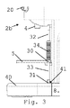
本発明によると、発生器は、収納機器構成を有し、図3に例示されるように、その中で、発生器の排出口31が本体40の開口41の中に動かされて収容される。
According to the present invention, the generator has a storage device configuration, in which the
排出口31の為の開口41は、本体40の上面42、特に、上面の周辺部に、或いは上面に隣接して、置かれてもよい。
The
本体40は、通常、廃液を集める為のリザーバを含み、或いはそれを形成する。このため、例えば湯及び/又は蒸気配送後に、排出口31からの流滴を本体40に集めることができる。本体40は、特に、リザーバを空にする為に、或いは/又はリザーバを洗浄する為に、取り外し可能であってもよい。
The
好ましい実施形態において、水及び/又は蒸気発生器は、湯垢除去機器構成のような洗浄機器構成を有し、その中で、発生器の排出口31は、本体40の開口41の中に動かされて収容される。
In a preferred embodiment, the water and / or steam generator has a cleaning equipment configuration, such as a descaling equipment configuration, in which the
機械1は、制御ユニットを有してもよく、制御ユニットは、発生器の排出口31が本体40の開口41から離れているとき、湯垢除去のような洗浄を防止するように配置される。
The
本体40により、飲料注出領域の範囲が決まる。
The
図1〜図3に例示されるように、飲料用排出口4は、本体40のほぼ直立して上方に置かれている。このため、使用者のカップ又はマグ(図示せず)は、排出口4を経て注出される飲料を集める為に本体40の上面42に配置可能である。
As illustrated in FIG. 1 to FIG. 3, the
例えばEP1867260に開示され、その内容が本願に参考の為に組み込まれるように、これらの図に例示された特定の実施形態において、支持体5は、排出口4の下にカップやマグを置く前に排出口4の下から支持体5を移動させるべきである。
In the particular embodiment illustrated in these figures, for example as disclosed in EP 1867260, the contents of which are incorporated herein by reference, the
上面42は、排出口31から流体を集め、更に、無駄になる滴下を排出口4から集める為に、リザーバの上方に置かれたグリッドにより形成される。このため、上面42は、特に、このグリッド内の装置により形成され、例えば面42の下に置かれた廃液リザーバの中に廃液を排出する。
The
図1〜図3に例示された実施形態において、湯及び/又は蒸気発生器は、その末端で排出口31を支える、使用者が移動可能な管31を含む。管31は、使用者により手動で操作機器構成の中に、更に、収納機器構成の中に移動可能である。管30は、収納機器構成内でほぼ直立されてもよい。
In the embodiment illustrated in FIGS. 1-3, the hot water and / or steam generator includes a user-
管30は、縦に移動可能である。特に、管30は、上流区間32と下流区間33とを含み、これらは、伸縮自在に配置されるので、下流区間33は上流区間32に関して縦に移動可能である。下流区間33は、スリーブ34を有し、スリーブ34は、管30の長さを調整する為に上流区間32にわたり摺動するように配置される。下流区間33は、スリーブ34の反対側で排出口31を支える。
The
さらに、管30は、旋回できるように機械1に装着されている。特に、区間32は、ほぼ水平軸35の周りに回転できるように装着され、もって、排出口31は、本体40から外側に離れて旋回可能であり、蒸気又は湯は、機械1の側部で保持された(例えば手で保持された)カップやマグの中に通される。あるいは、蒸気又は湯用管は、旋回可能に形成可能であり、別の方法で、蒸気又は湯を支持体5又は本体40に置かれたカップやマグの中に通す為に本体40の上方で内側に移動可能である。
Furthermore, the
1 飲料調製機
2 ハウジング
2a 最上面
2b 前面
3 タンク、液体リザーバ
4 飲料用排出口
5, カップ支持体、注出領域
6, 原料コレクタ
7 通路
8 ベース、足部
9 電気コード
10 手動作動ハンドル
11 末端
12 接触面、駆動部、駆動部分
20 ユーザーインターフェース
29 ユーザーインターフェース
30 管
31 排出口
32 上流区間
33 下流区間
34 スリーブ
35 水平軸
40 カップ支持体
41 開口
42 上面
DESCRIPTION OF
Claims (15)
前記発生器が収納機器構成を有し、その内部で、前記発生器の前記排出口が前記本体の前記開口に移動されて収容されることを特徴とする、飲料調製機。 A beverage preparation machine (1) comprising a body (40) having an opening (41), a movable discharge port (31), a generator and a hot water and / or steam generator having a discharge port, The hot water and / or steam generator with an operating equipment configuration for delivering hot water and / or steam via an outlet,
The beverage generator according to claim 1, wherein the generator has a storage device configuration, and the discharge port of the generator is moved to and stored in the opening of the main body.
Applications Claiming Priority (3)
| Application Number | Priority Date | Filing Date | Title |
|---|---|---|---|
| EP10163638.9 | 2010-05-21 | ||
| EP10163638 | 2010-05-21 | ||
| PCT/EP2011/058225 WO2011144722A1 (en) | 2010-05-21 | 2011-05-20 | Storable hot water or steam delivery device |
Publications (2)
| Publication Number | Publication Date |
|---|---|
| JP2013526358A true JP2013526358A (en) | 2013-06-24 |
| JP2013526358A5 JP2013526358A5 (en) | 2014-07-03 |
Family
ID=42751885
Family Applications (1)
| Application Number | Title | Priority Date | Filing Date |
|---|---|---|---|
| JP2013510632A Ceased JP2013526358A (en) | 2010-05-21 | 2011-05-20 | Storeable hot water or steam delivery device |
Country Status (12)
| Country | Link |
|---|---|
| US (1) | US20130112085A1 (en) |
| EP (1) | EP2571407B1 (en) |
| JP (1) | JP2013526358A (en) |
| CN (1) | CN102905586B (en) |
| AU (1) | AU2011254530B2 (en) |
| BR (1) | BR112012029641A2 (en) |
| CA (1) | CA2800017A1 (en) |
| ES (1) | ES2466865T3 (en) |
| PT (1) | PT2571407E (en) |
| RU (1) | RU2557492C2 (en) |
| WO (1) | WO2011144722A1 (en) |
| ZA (1) | ZA201209688B (en) |
Families Citing this family (7)
| Publication number | Priority date | Publication date | Assignee | Title |
|---|---|---|---|---|
| US8991795B2 (en) * | 2013-03-15 | 2015-03-31 | Briggo, Inc. | Frothing assembly and method of operating the same |
| CN110840261B (en) | 2013-09-30 | 2022-10-18 | 布瑞威利私人有限公司 | Foaming device suitable for being matched with kettle |
| CN107920684B (en) * | 2015-09-04 | 2020-11-06 | 雀巢产品有限公司 | Beverage machine with ergonomic outlet |
| AU2017231093B2 (en) * | 2016-03-07 | 2020-03-12 | Breville Pty Limited | Steam wand |
| AU201711148S (en) * | 2016-09-06 | 2017-03-15 | SOCIAƒA©TAƒA© DES PRODUITS NESTLAƒA© S A | A coffee machine |
| AU201711682S (en) * | 2016-09-30 | 2017-04-07 | SOCIAƒA©TAƒA© DES PRODUITS NESTLAƒA© S A | A coffee machine |
| US11432674B2 (en) | 2017-02-28 | 2022-09-06 | Societe Des Produits Nestle S.A. | Dispenser with parallel dispensing paths |
Citations (5)
| Publication number | Priority date | Publication date | Assignee | Title |
|---|---|---|---|---|
| JPS62211024A (en) * | 1986-03-10 | 1987-09-17 | ブレベツテイ・ガツギア・ソシエタ・ペル・アチオ−ニ | Expresso coffee maker |
| JPH03119328U (en) * | 1990-03-16 | 1991-12-09 | ||
| JP2006341097A (en) * | 2005-06-07 | 2006-12-21 | Nestec Sa | Beverage machine with drip tray device for recipient of different heights |
| WO2009122038A1 (en) * | 2008-03-26 | 2009-10-08 | Seb S.A. | Drink preparing machine including a built-in container for cleaning using steam nozzle |
| US20090301310A1 (en) * | 2004-12-21 | 2009-12-10 | Seb S.A. | Coffee machine proviced with a steam nozzle |
Family Cites Families (30)
| Publication number | Priority date | Publication date | Assignee | Title |
|---|---|---|---|---|
| JPS58222014A (en) | 1982-06-18 | 1983-12-23 | Taisho Pharmaceut Co Ltd | Prostaglandin e1 oil emulsion |
| IT8322999V0 (en) * | 1983-09-16 | 1983-09-16 | Cavalli Alfredo | ELEMENT FOR THE DISPENSING OF STEAM PARTICULARLY DESIGNED TO BE APPLIED TO COFFEE MACHINES. |
| IT1263761B (en) | 1993-01-19 | 1996-08-29 | DEVICE FOR THE PRODUCTION OF FOAMING STEAM, ESPECIALLY FOR EQUIPMENT FOR THE PRODUCTION OF HOT DRINKS | |
| US5423245A (en) * | 1994-04-13 | 1995-06-13 | Bunn-O-Matic Corporation | Milk foaming device |
| US5638740A (en) * | 1995-02-24 | 1997-06-17 | Cai; Zhihua | Apparatus for brewing espresso and cappuccino |
| DE19611450C1 (en) | 1996-03-22 | 1997-07-03 | Braun Ag | Device for heating and foaming milk for preparation of cappuccino drink |
| DE19921483C1 (en) | 1999-05-08 | 2000-08-17 | Braun Gmbh | Appts for foaming milk has a steam pipe with an end jet extending from a base body with a sliding vertical movement in a housing to move the jet in and out of the milk without holding the vessel |
| IT1313666B1 (en) * | 1999-10-13 | 2002-09-09 | De Longhi Spa | ESPRESSO COFFEE MACHINE PARTICULARLY FOR DOMESTIC USE. |
| US6459854B1 (en) | 2000-01-24 | 2002-10-01 | Nestec S.A. | Process and module for heating liquid |
| IN192798B (en) * | 2000-03-15 | 2004-05-22 | Fianara Int Bv | |
| PT1501398E (en) | 2002-05-06 | 2007-01-31 | Gruppo Cimbali Spa | Device for heating and working up milk |
| DK1380243T3 (en) | 2002-07-12 | 2008-08-25 | Nestec Sa | Device for heating a liquid |
| EP1495702A1 (en) | 2003-07-10 | 2005-01-12 | Nestec S.A. | Device for the extraction of a cartridge |
| EP1634520A1 (en) | 2004-09-13 | 2006-03-15 | Nestec S.A. | Device and method for heating a liquid |
| EP1656863B1 (en) * | 2004-11-11 | 2011-03-02 | Nestec S.A. | Self-cleaning mixing head for producing a milk-based mixture and beverage production machines comprising such a mixing head |
| GB2438803B (en) * | 2005-02-28 | 2008-11-26 | Coffee Nation Ltd | Apparatus for preparing beverages |
| EP1968894A1 (en) | 2005-07-16 | 2008-09-17 | Clariant International Ltd. | Method for producing coloured nanocorundum |
| ATE470384T1 (en) | 2005-09-20 | 2010-06-15 | Nestec Sa | THERMOBLOCK BASED BEVERAGE PRODUCTION DEVICE WITH A BREWING CHAMBER |
| ATE381898T1 (en) | 2005-10-21 | 2008-01-15 | Gruppo Cimbali Spa | METHOD FOR HEATING AND FOAMING MILK AND DEVICE FOR CARRYING OUT THIS METHOD |
| ES2332378T3 (en) | 2006-05-24 | 2010-02-03 | Nestec S.A. | INFUSION DEVICE FOR CAPSULE WITH VARIABLE TRANSMISSION RELATIONSHIP CLOSURE MECHANISM. |
| PL2189088T3 (en) | 2006-06-16 | 2013-10-31 | Nestec Sa | Beverage distribution apparatus with support system and droplet recuperation for containers with different sizes |
| DE102006043903B3 (en) | 2006-09-19 | 2008-02-28 | BSH Bosch und Siemens Hausgeräte GmbH | Coffee machine, to dispense coffee in cup portions, has a hot brew outflow with a relative movement against the steam/foamed milk outflow |
| WO2009043630A2 (en) | 2007-10-04 | 2009-04-09 | Nestec S.A. | Beverage brewing unit |
| CA2707854C (en) | 2007-12-12 | 2016-02-02 | Nestec S.A. | Used capsule or pod receptacle for liquid food or beverage machines |
| EP2070454B1 (en) | 2007-12-12 | 2015-07-15 | Nestec S.A. | Beverage production machines comprising a plurality of core units |
| DE102008005361A1 (en) * | 2008-01-21 | 2009-07-23 | BSH Bosch und Siemens Hausgeräte GmbH | Steam pipe for a coffee machine |
| RU2497429C2 (en) | 2008-04-22 | 2013-11-10 | Нестек С.А. | Modula design device for preparation of beverages |
| US8695484B2 (en) | 2008-05-07 | 2014-04-15 | Nestec S.A. | Used capsule collector for beverage devices |
| CN201239028Y (en) * | 2008-07-25 | 2009-05-20 | 刘守军 | Drinking machine with cleaning and disinfecting device |
| FR2935881B1 (en) * | 2008-09-16 | 2010-10-08 | Seb Sa | FOAM PRODUCTION SYSTEM FOR HOUSEHOLD DRINKING PRODUCTION APPARATUS |
-
2011
- 2011-05-20 US US13/700,908 patent/US20130112085A1/en not_active Abandoned
- 2011-05-20 WO PCT/EP2011/058225 patent/WO2011144722A1/en active Application Filing
- 2011-05-20 EP EP11720519.5A patent/EP2571407B1/en active Active
- 2011-05-20 CA CA2800017A patent/CA2800017A1/en not_active Abandoned
- 2011-05-20 ES ES11720519.5T patent/ES2466865T3/en active Active
- 2011-05-20 RU RU2012155627/12A patent/RU2557492C2/en not_active IP Right Cessation
- 2011-05-20 CN CN201180025215.3A patent/CN102905586B/en active Active
- 2011-05-20 JP JP2013510632A patent/JP2013526358A/en not_active Ceased
- 2011-05-20 PT PT11720519T patent/PT2571407E/en unknown
- 2011-05-20 AU AU2011254530A patent/AU2011254530B2/en not_active Expired - Fee Related
- 2011-05-20 BR BR112012029641A patent/BR112012029641A2/en not_active IP Right Cessation
-
2012
- 2012-12-20 ZA ZA2012/09688A patent/ZA201209688B/en unknown
Patent Citations (5)
| Publication number | Priority date | Publication date | Assignee | Title |
|---|---|---|---|---|
| JPS62211024A (en) * | 1986-03-10 | 1987-09-17 | ブレベツテイ・ガツギア・ソシエタ・ペル・アチオ−ニ | Expresso coffee maker |
| JPH03119328U (en) * | 1990-03-16 | 1991-12-09 | ||
| US20090301310A1 (en) * | 2004-12-21 | 2009-12-10 | Seb S.A. | Coffee machine proviced with a steam nozzle |
| JP2006341097A (en) * | 2005-06-07 | 2006-12-21 | Nestec Sa | Beverage machine with drip tray device for recipient of different heights |
| WO2009122038A1 (en) * | 2008-03-26 | 2009-10-08 | Seb S.A. | Drink preparing machine including a built-in container for cleaning using steam nozzle |
Also Published As
| Publication number | Publication date |
|---|---|
| AU2011254530A1 (en) | 2012-11-22 |
| US20130112085A1 (en) | 2013-05-09 |
| ZA201209688B (en) | 2014-05-28 |
| PT2571407E (en) | 2014-05-02 |
| BR112012029641A2 (en) | 2016-08-02 |
| RU2012155627A (en) | 2014-06-27 |
| WO2011144722A1 (en) | 2011-11-24 |
| CN102905586A (en) | 2013-01-30 |
| ES2466865T3 (en) | 2014-06-11 |
| AU2011254530B2 (en) | 2015-08-27 |
| EP2571407B1 (en) | 2014-04-16 |
| RU2557492C2 (en) | 2015-07-20 |
| CN102905586B (en) | 2015-11-25 |
| CA2800017A1 (en) | 2011-11-24 |
| EP2571407A1 (en) | 2013-03-27 |
Similar Documents
| Publication | Publication Date | Title |
|---|---|---|
| RU2748515C2 (en) | Beverage preparation device with ergonomic control | |
| JP5469083B2 (en) | Fluid food or beverage apparatus with drip tray and cup support | |
| EP2592980B1 (en) | Secure cup support for beverage machine | |
| EP2579754B1 (en) | Ergonomic service arrangement for beverage machine | |
| RU2549060C2 (en) | Beverage dispensing device with safe cleaning unit | |
| CN103188972B (en) | There is the ergonomical handle of user interface | |
| JP2013526358A (en) | Storeable hot water or steam delivery device | |
| JP2017094137A (en) | Beverage preparation device | |
| RU2752302C2 (en) | Liquid dispensing device with drop limiter | |
| JP2013526358A5 (en) | ||
| JP2013544172A (en) | Beverage preparation device with droplet collector | |
| EP2632310A1 (en) | Beverage machine with a handy outlet | |
| RU2753221C2 (en) | Liquid dispensing device with speed regulator | |
| WO2019121865A1 (en) | Beverage preparation machine with handy drop stop | |
| WO2013137728A1 (en) | Preparation of a liquid food product for human consumption, for example an arabic coffee beverage. |
Legal Events
| Date | Code | Title | Description |
|---|---|---|---|
| A524 | Written submission of copy of amendment under section 19 (pct) |
Free format text: JAPANESE INTERMEDIATE CODE: A524 Effective date: 20140516 |
|
| A621 | Written request for application examination |
Free format text: JAPANESE INTERMEDIATE CODE: A621 Effective date: 20140516 |
|
| A977 | Report on retrieval |
Free format text: JAPANESE INTERMEDIATE CODE: A971007 Effective date: 20150325 |
|
| A131 | Notification of reasons for refusal |
Free format text: JAPANESE INTERMEDIATE CODE: A131 Effective date: 20150512 |
|
| A521 | Written amendment |
Free format text: JAPANESE INTERMEDIATE CODE: A523 Effective date: 20150812 |
|
| A01 | Written decision to grant a patent or to grant a registration (utility model) |
Free format text: JAPANESE INTERMEDIATE CODE: A01 Effective date: 20160112 |
|
| A045 | Written measure of dismissal of application |
Free format text: JAPANESE INTERMEDIATE CODE: A045 Effective date: 20160531 |