JP2013523902A - Method for producing hydrogenated nitrile rubber free from water and solvent - Google Patents
Method for producing hydrogenated nitrile rubber free from water and solvent Download PDFInfo
- Publication number
- JP2013523902A JP2013523902A JP2013500462A JP2013500462A JP2013523902A JP 2013523902 A JP2013523902 A JP 2013523902A JP 2013500462 A JP2013500462 A JP 2013500462A JP 2013500462 A JP2013500462 A JP 2013500462A JP 2013523902 A JP2013523902 A JP 2013523902A
- Authority
- JP
- Japan
- Prior art keywords
- extruder
- fluid
- nitrile rubber
- hydrogenated nitrile
- weight
- Prior art date
- Legal status (The legal status is an assumption and is not a legal conclusion. Google has not performed a legal analysis and makes no representation as to the accuracy of the status listed.)
- Granted
Links
Images
Classifications
-
- C—CHEMISTRY; METALLURGY
- C08—ORGANIC MACROMOLECULAR COMPOUNDS; THEIR PREPARATION OR CHEMICAL WORKING-UP; COMPOSITIONS BASED THEREON
- C08L—COMPOSITIONS OF MACROMOLECULAR COMPOUNDS
- C08L9/00—Compositions of homopolymers or copolymers of conjugated diene hydrocarbons
- C08L9/02—Copolymers with acrylonitrile
-
- C—CHEMISTRY; METALLURGY
- C08—ORGANIC MACROMOLECULAR COMPOUNDS; THEIR PREPARATION OR CHEMICAL WORKING-UP; COMPOSITIONS BASED THEREON
- C08C—TREATMENT OR CHEMICAL MODIFICATION OF RUBBERS
- C08C1/00—Treatment of rubber latex
- C08C1/02—Chemical or physical treatment of rubber latex before or during concentration
- C08C1/075—Concentrating
- C08C1/12—Concentrating by evaporation
-
- C—CHEMISTRY; METALLURGY
- C08—ORGANIC MACROMOLECULAR COMPOUNDS; THEIR PREPARATION OR CHEMICAL WORKING-UP; COMPOSITIONS BASED THEREON
- C08C—TREATMENT OR CHEMICAL MODIFICATION OF RUBBERS
- C08C19/00—Chemical modification of rubber
- C08C19/02—Hydrogenation
-
- C—CHEMISTRY; METALLURGY
- C08—ORGANIC MACROMOLECULAR COMPOUNDS; THEIR PREPARATION OR CHEMICAL WORKING-UP; COMPOSITIONS BASED THEREON
- C08C—TREATMENT OR CHEMICAL MODIFICATION OF RUBBERS
- C08C2/00—Treatment of rubber solutions
-
- C—CHEMISTRY; METALLURGY
- C08—ORGANIC MACROMOLECULAR COMPOUNDS; THEIR PREPARATION OR CHEMICAL WORKING-UP; COMPOSITIONS BASED THEREON
- C08C—TREATMENT OR CHEMICAL MODIFICATION OF RUBBERS
- C08C2/00—Treatment of rubber solutions
- C08C2/02—Purification
-
- C—CHEMISTRY; METALLURGY
- C08—ORGANIC MACROMOLECULAR COMPOUNDS; THEIR PREPARATION OR CHEMICAL WORKING-UP; COMPOSITIONS BASED THEREON
- C08F—MACROMOLECULAR COMPOUNDS OBTAINED BY REACTIONS ONLY INVOLVING CARBON-TO-CARBON UNSATURATED BONDS
- C08F236/00—Copolymers of compounds having one or more unsaturated aliphatic radicals, at least one having two or more carbon-to-carbon double bonds
- C08F236/02—Copolymers of compounds having one or more unsaturated aliphatic radicals, at least one having two or more carbon-to-carbon double bonds the radical having only two carbon-to-carbon double bonds
- C08F236/04—Copolymers of compounds having one or more unsaturated aliphatic radicals, at least one having two or more carbon-to-carbon double bonds the radical having only two carbon-to-carbon double bonds conjugated
- C08F236/12—Copolymers of compounds having one or more unsaturated aliphatic radicals, at least one having two or more carbon-to-carbon double bonds the radical having only two carbon-to-carbon double bonds conjugated with nitriles
-
- C—CHEMISTRY; METALLURGY
- C08—ORGANIC MACROMOLECULAR COMPOUNDS; THEIR PREPARATION OR CHEMICAL WORKING-UP; COMPOSITIONS BASED THEREON
- C08F—MACROMOLECULAR COMPOUNDS OBTAINED BY REACTIONS ONLY INVOLVING CARBON-TO-CARBON UNSATURATED BONDS
- C08F6/00—Post-polymerisation treatments
- C08F6/001—Removal of residual monomers by physical means
- C08F6/003—Removal of residual monomers by physical means from polymer solutions, suspensions, dispersions or emulsions without recovery of the polymer therefrom
-
- C—CHEMISTRY; METALLURGY
- C08—ORGANIC MACROMOLECULAR COMPOUNDS; THEIR PREPARATION OR CHEMICAL WORKING-UP; COMPOSITIONS BASED THEREON
- C08F—MACROMOLECULAR COMPOUNDS OBTAINED BY REACTIONS ONLY INVOLVING CARBON-TO-CARBON UNSATURATED BONDS
- C08F6/00—Post-polymerisation treatments
- C08F6/06—Treatment of polymer solutions
- C08F6/10—Removal of volatile materials, e.g. solvents
-
- C—CHEMISTRY; METALLURGY
- C08—ORGANIC MACROMOLECULAR COMPOUNDS; THEIR PREPARATION OR CHEMICAL WORKING-UP; COMPOSITIONS BASED THEREON
- C08F—MACROMOLECULAR COMPOUNDS OBTAINED BY REACTIONS ONLY INVOLVING CARBON-TO-CARBON UNSATURATED BONDS
- C08F8/00—Chemical modification by after-treatment
- C08F8/04—Reduction, e.g. hydrogenation
-
- C—CHEMISTRY; METALLURGY
- C08—ORGANIC MACROMOLECULAR COMPOUNDS; THEIR PREPARATION OR CHEMICAL WORKING-UP; COMPOSITIONS BASED THEREON
- C08L—COMPOSITIONS OF MACROMOLECULAR COMPOUNDS
- C08L15/00—Compositions of rubber derivatives
- C08L15/005—Hydrogenated nitrile rubber
Landscapes
- Chemical & Material Sciences (AREA)
- Health & Medical Sciences (AREA)
- Chemical Kinetics & Catalysis (AREA)
- Medicinal Chemistry (AREA)
- Polymers & Plastics (AREA)
- Organic Chemistry (AREA)
- General Chemical & Material Sciences (AREA)
- Dispersion Chemistry (AREA)
- Addition Polymer Or Copolymer, Post-Treatments, Or Chemical Modifications (AREA)
Abstract
本発明は、水および溶媒を含まない水素化ニトリルゴムポリマーの製造方法、水素化ニトリルゴムおよびその使用に関する。水素化ニトリルゴムは、少なくとも1つの共役ジエン、少なくとも1つのα,β−不飽和ニトリルおよび任意選択的に1つ以上の共重合性モノマーに由来する繰り返し単位を含み、最大でも20000Pa*s(100℃でおよび1/秒の剪断速度で測定される)、好ましくは最大でも10000Pa*s、より好ましくは最大でも5000Pa*s、最も好ましくは最大でも1000Pa*sの粘度を有する。 The present invention relates to a method for producing a hydrogenated nitrile rubber polymer free from water and a solvent, a hydrogenated nitrile rubber and use thereof. The hydrogenated nitrile rubber comprises repeating units derived from at least one conjugated diene, at least one α, β-unsaturated nitrile and optionally one or more copolymerizable monomers, and at most 20000 Pa * s (100 At a shear rate of 1 / sec.), Preferably at most 10,000 Pa * s, more preferably at most 5000 Pa * s, most preferably at most 1000 Pa * s.
Description
本発明は、水および溶媒を含まない水素化ニトリルゴム、その製造方法ならびにその使用に関する。 The present invention relates to hydrogenated nitrile rubber free of water and solvent, a process for its production and its use.
α,β−不飽和ニトリルと共役ジエンおよび任意選択的に1つ以上のさらなる共重合性ターモノマーとの共重合は、いわゆるニトリルゴム(略して「NBR」とも言われる)をもたらす。前記共重合は典型的には乳化法によって実施され、乳化法は先ずNBRラテックスを与え、ラテックスは次に、大抵は塩または酸を凝固剤として使用してNBR固体を単離するために凝固させられる。最近になってやっと、有機溶媒中のRAFT技術(可逆的付加−開裂技術」)によるNBRの新規製造方法が開発され、これは、出願人による未公開の先の特許出願の主題である。 Copolymerization of α, β-unsaturated nitriles with conjugated dienes and optionally one or more further copolymerizable termonomers results in so-called nitrile rubber (also referred to as “NBR” for short). The copolymerization is typically carried out by an emulsification method, which first provides an NBR latex, which is then coagulated to isolate the NBR solid, usually using a salt or acid as a coagulant. It is done. Only recently has a new process for the production of NBR developed by RAFT technology in organic solvents (reversible addition-cleavage technology), which is the subject of an unpublished earlier patent application.
略して「HNBR」とも言われる、水素化ニトリルゴムは、NBRのその後の水素化によって製造される。したがって、共重合ジエン単位のC=C二重結合は、HNBRにおいては完全にまたは部分的に水素化されている。共重合ジエン単位の水素化度は通常、50〜100%の範囲にある。水素化ニトリルゴムは、非常に良好な耐熱性、優れた耐オゾン性および耐化学薬品性およびまた優れた耐油性を有するスペシャルティゴムである。さらにHNBRはまた、非常に良好な機械的特性、特に高い耐摩耗性を有する。HNBRは、広範囲の様々な用途において幅広い使用を見いだしてきており、たとえば自動車部門においてシール、ホース、ベルトおよび減衰エレメント用に、また油生産の分野で固定子、坑井シールおよびバルブシール用に、ならびにまた航空機産業、電気産業、機械建造および造船において多数の部品用に使用されている。 Hydrogenated nitrile rubber, also referred to as “HNBR” for short, is produced by subsequent hydrogenation of NBR. Thus, the C═C double bond of the copolymerized diene unit is fully or partially hydrogenated in HNBR. The degree of hydrogenation of the copolymerized diene units is usually in the range of 50 to 100%. Hydrogenated nitrile rubber is a specialty rubber having very good heat resistance, excellent ozone resistance and chemical resistance, and also excellent oil resistance. Furthermore, HNBR also has very good mechanical properties, in particular high wear resistance. HNBR has found wide use in a wide variety of applications, for example for seals, hoses, belts and damping elements in the automotive sector and for stators, well seals and valve seals in the field of oil production. And also used for numerous components in the aircraft industry, electrical industry, machine construction and shipbuilding.
ほとんどの商業的に入手可能なHNBRグレードは通常、約100000〜500000の範囲の数平均分子量Mn(測定方法:ポリスチレン標準に対するゲル浸透クロマトグラフィー(GPC))に相当する、55〜120の範囲のムーニー(Mooney)粘度(ML、1+4、100℃)を有する。本明細書において測定される、分子量分布の幅を示す、多分散性指数PDI(PDI=Mw/Mn、ここで、Mwは重量平均分子量であり、Mnは数平均分子量である)は頻繁に、3またはそれより十分に上の値を有する。残存二重結合含有率は通常、0〜18%の範囲にある(NMRまたはIR分光法によって測定される)。しかし、用語「十分に水素化されたグレード」は、残存二重結合含有率が約0.9%以下であるときに本技術分野において用いられる。 Most commercially available HNBR grades usually correspond to a number average molecular weight Mn in the range of about 100,000 to 500,000 (measuring method: gel permeation chromatography (GPC) against polystyrene standards) in the range of 55 to 120. (Mooney) Viscosity (ML, 1 + 4, 100 ° C.). The polydispersity index PDI (PDI = Mw / Mn, where Mw is the weight average molecular weight and Mn is the number average molecular weight), indicating the width of the molecular weight distribution, as measured herein, is frequently Has a value of 3 or well above. The residual double bond content is usually in the range of 0-18% (measured by NMR or IR spectroscopy). However, the term “fully hydrogenated grade” is used in the art when the residual double bond content is about 0.9% or less.
120以下の上述のムーニー粘度を有するHNBRグレードの加工性は制限を受ける。多くの用途向けに、より低いモル質量およびより低いムーニー粘度を有するHNBRグレードを、有することが望ましい。なぜなら、このことにより加工性が著しく向上するからである。しかし、低い分子量および約55までの範囲のムーニー粘度(ML 1+4、100℃)を有するHNBRの製造は、主として2つの理由で確立された製造方法では長い間可能ではなかった:第1に、ムーニー粘度のかなりの増加(いわゆるムーニー増加率、「MIR」)がHNBRへのNBRの水素化中に起こる。このMIRは、ポリマーグレード、水素化レベルおよびNBR原料の性質に依存して、約2以上であり、特に、NBR原料のムーニー粘度の減少とともに増加する。第2に、水素化のために使用されるNBR原料のモル質量は意のままに下げることはできない、なぜなら、下げると、粘着性が高くなりすぎるため、利用可能な工業プラントでの加工が可能ではなくなるからである。確立された工業プラントで困難なしに加工することができるNBR原料の最低のムーニー粘度は、約25ムーニー単位(ML 1+4、100℃)の範囲内にある。この下限は、粘着性がACN含有率とともに上昇するのでNBRのACN含有率の増加とともに上がるであろう。それから得られるHNBRのムーニー粘度は、ほぼ55以上のムーニー単位(ML 1+4、100℃)である。ムーニー粘度は、ASTM標準D 1646に従って測定される。 The processability of HNBR grades having the Mooney viscosity above 120 is limited. For many applications, it is desirable to have a HNBR grade that has a lower molar mass and a lower Mooney viscosity. This is because the processability is remarkably improved. However, the production of HNBR having a low molecular weight and a Mooney viscosity (ML 1 + 4, 100 ° C.) in the range up to about 55 has not been possible for a long time with established manufacturing methods mainly for two reasons: First, Mooney A significant increase in viscosity (so-called Mooney Increasing Rate, “MIR”) occurs during the hydrogenation of NBR to HNBR. This MIR is about 2 or higher, depending on the polymer grade, hydrogenation level, and nature of the NBR feed, and particularly increases with decreasing Mooney viscosity of the NBR feed. Second, the molar mass of the NBR feedstock used for hydrogenation cannot be reduced at will, because if it is lowered, it becomes too sticky and can be processed in available industrial plants Because it is not. The lowest Mooney viscosity of NBR feedstock that can be processed without difficulty in an established industrial plant is in the range of about 25 Mooney units (ML 1 + 4, 100 ° C.). This lower limit will increase with increasing ACN content of NBR as tackiness increases with ACN content. The Mooney viscosity of the resulting HNBR is approximately 55 or more Mooney units (ML 1 + 4, 100 ° C.). Mooney viscosity is measured according to ASTM standard D 1646.
HNBRのポリマー鎖長を短くするための多くの試みが、分解によって、たとえばロールミルで、またはスクリュー装置において、たとえば熱機械的処理(素練り)によって、行われてきた((特許文献1))。しかし、この熱機械的分解は、ヒドロキシル、ケト、カルボン酸およびエステル基などの官能基が部分酸化の結果として分子中に組み込まれ、そして、さらに、ポリマーの微細構造が実質的に変わるという欠点を有する。 Many attempts to shorten the polymer chain length of HNBR have been made by decomposition, for example in a roll mill or in a screw device, for example by thermomechanical treatment (powdering) (patent document 1). However, this thermomechanical degradation has the disadvantage that functional groups such as hydroxyl, keto, carboxylic acid and ester groups are incorporated into the molecule as a result of partial oxidation, and further the polymer microstructure is substantially altered. Have.
最近、この問題は、分解によりNBRの分子量を低下させ、それによって30ムーニー単位未満のムーニー粘度(ML 1+4、100℃)または70,000g/モル未満の数平均分子量Mnを得ることによって解決された。分子量のそのような低下は、低分子量1−オレフィンが添加されてもよい交差メタセシスによって達成される。NBRのメタセシスは、たとえば(特許文献2)、(特許文献3)および(特許文献4)に記載されており、極性基、特にニトリル基に耐性がある特有のメタセシス触媒を使用する。それは典型的には、使用される触媒を失活させない、そしてまたその他のいかなる方法でも反応に悪影響を及ぼさない好適な有機溶媒中で実施される。好ましい溶媒としては、ジクロロメタン、クロロホルム、1,2−ジクロロエタン、1,1,2−トリクロロエタン、モノクロロベンゼン、ジクロロベンゼン、トリクロロベンゼン、ベンゼン、トルエン、キシレン、メチルエチルケトン、酢酸エチル、アセトン、テトラヒドロフラン、テトラヒドロピランおよびジオキサンが挙げられるが、それらに限定されない。好ましい一溶媒はモノクロロベンゼンである。好ましくはメタセシスは、分解反応が完了した後でそれがその後の水素化にかけられる前に分解ニトリルゴムが溶媒から必ずしも単離される必要がないようにその後の水素化反応と同じ溶媒中で実施される。水素化は、均一または不均一水素化触媒を使用して実施することができる。使用される触媒は典型的にはロジウムまたはルテニウムをベースにしているが、金属としてか好ましくは金属化合物の形態でのどちらかで白金、イリジウム、パラジウム、オスミウム、コバルトまたは銅を使用することもまた可能である。好ましい触媒は、たとえばトリス(トリフェニルホスフィン)ロジウム(I)クロリド、トリス(トリフェニルホスフィン)ロジウム(III)クロリドおよびトリス(ジメチルスルホキシド)ロジウム(III)クロリドおよびまた式(C6H5)3P)4RhHのテトラキス(トリフェニルホスフィン)ロジウムヒドリドならびにトリフェニルホスフィンのすべてまたは一部がトリシクロヘキシルホスフィンで置き換えられた相当する触媒のような均一触媒である。さらに、メタセシス反応のためにさもなければ典型的に使用されるが、水素化活性もまた示す、周知のGrubbs型金属錯体触媒(たとえばGrubbs IおよびGrubbs II触媒)を使用することもまた可能である。 Recently, this problem has been solved by reducing the molecular weight of NBR by decomposition, thereby obtaining a Mooney viscosity of less than 30 Mooney units (ML 1 + 4, 100 ° C.) or a number average molecular weight Mn of less than 70,000 g / mol. . Such a reduction in molecular weight is achieved by cross-metathesis where low molecular weight 1-olefins may be added. The metathesis of NBR is described in, for example, (Patent Document 2), (Patent Document 3) and (Patent Document 4), and uses a specific metathesis catalyst resistant to polar groups, particularly nitrile groups. It is typically carried out in a suitable organic solvent that does not deactivate the catalyst used and does not adversely affect the reaction in any other way. Preferred solvents include dichloromethane, chloroform, 1,2-dichloroethane, 1,1,2-trichloroethane, monochlorobenzene, dichlorobenzene, trichlorobenzene, benzene, toluene, xylene, methyl ethyl ketone, ethyl acetate, acetone, tetrahydrofuran, tetrahydropyran and Examples include but are not limited to dioxane. One preferred solvent is monochlorobenzene. Preferably the metathesis is carried out in the same solvent as the subsequent hydrogenation reaction so that after the decomposition reaction is complete and before it is subjected to subsequent hydrogenation, the decomposed nitrile rubber does not necessarily have to be isolated from the solvent. . Hydrogenation can be carried out using a homogeneous or heterogeneous hydrogenation catalyst. The catalysts used are typically based on rhodium or ruthenium, but it is also possible to use platinum, iridium, palladium, osmium, cobalt or copper, either as a metal or preferably in the form of a metal compound. Is possible. Preferred catalysts are, for example, tris (triphenylphosphine) rhodium (I) chloride, tris (triphenylphosphine) rhodium (III) chloride and tris (dimethylsulfoxide) rhodium (III) chloride and also the formula (C 6 H 5 ) 3 P 4 RhH tetrakis (triphenylphosphine) rhodium hydride and homogeneous catalysts such as the corresponding catalyst in which all or part of the triphenylphosphine is replaced by tricyclohexylphosphine. Furthermore, it is also possible to use well-known Grubbs-type metal complex catalysts (eg Grubbs I and Grubbs II catalysts) that are otherwise typically used for metathesis reactions but also exhibit hydrogenation activity. .
水素化後に触媒および/または触媒に含まれる金属は、HNBR溶液から除去することができる。反応媒体に溶解していない不均一触媒の場合には、触媒は、濾過または遠心分離によって容易に除去することができる。均一触媒の場合には、様々な基によって大抵は官能化されているイオン交換樹脂を使用して触媒および触媒残渣を除去することができる。 The catalyst and / or metal contained in the catalyst after hydrogenation can be removed from the HNBR solution. In the case of a heterogeneous catalyst not dissolved in the reaction medium, the catalyst can be easily removed by filtration or centrifugation. In the case of homogeneous catalysts, ion exchange resins that are mostly functionalized with various groups can be used to remove the catalyst and catalyst residues.
HNBRはしたがって典型的には、
(A1)HNBR溶液がスチームと直接接触させられる凝固(「スチームストリッピング」)、または
(A2)HNBR溶液が溶媒を蒸発させるために加熱回転ドラム上へ落とされるドラム乾燥法、または
(A3)貧溶媒がHNBRを沈澱させるためにHNBR溶液に加えられる方法
によって反応液から単離される。
HNBR is therefore typically
(A1) solidification in which the HNBR solution is brought into direct contact with steam (“steam stripping”), or (A2) a drum drying method in which the HNBR solution is dropped onto a heated rotating drum to evaporate the solvent, or (A3) poor It is isolated from the reaction by a method in which a solvent is added to the HNBR solution to precipitate HNBR.
しかし、すべての前述の凝固方法には、エネルギー消費量が非常に高いという問題がある。 However, all the aforementioned solidification methods have the problem of very high energy consumption.
方法(A1)を用いると、大量のスチームが、溶媒を蒸発させるためのみならず、ストリッピングドラムの全水内容物を加熱するおよび高温に維持するためにも必要である。追加のスチーム添加がまた、ストリッピングドラム中の溶媒の分圧を下げることによって残留量の溶媒をストリップオフするために必要である。 Using method (A1), a large amount of steam is required not only to evaporate the solvent, but also to heat and maintain the total water content of the stripping drum. Additional steam addition is also necessary to strip off residual amounts of solvent by reducing the solvent partial pressure in the stripping drum.
方法(A3)を用いると、エネルギー消費は、2つの溶媒を蒸留によって分離するための取組みによって生じ、蒸留はまた爆発から防護される特有の装備を必要とする。 With method (A3), energy consumption is caused by efforts to separate the two solvents by distillation, which also requires specific equipment that is protected from explosions.
方法(A1)はまた、凝固後のスラリー中のHNBRの濃度が一般に1.5〜12重量%であるにすぎないので、大量の水を利用している。このスラリーからのすべての水が廃水を構成し、後で廃棄処分されなければならない。 Method (A1) also utilizes large amounts of water since the concentration of HNBR in the slurry after coagulation is generally only 1.5-12% by weight. All water from this slurry constitutes wastewater and must be disposed of later.
ストリッピング法(A1)のさらなる欠点は、(時々)粘着性の小片とゴム小片の十分に制御できないサイズとに起因する。すなわち、ゴム小片が粘着性である場合にはゴム小片はストリッピング装置から完全に除去することができず、ポリマー収率の低下が観察される。形成されたゴム小片が非常に大きい場合にはストリッピング効率は低下する。また、これまで原因が分かっていないが、HNBRムーニー粘度の増加がストリッピングプロセス中に起こり得る。これは、粘着性がアクリロニトリル含有率の増加とともに増加するので、高いアクリロニトリル含有率の水素化ニトリルゴムについて特に当てはまる。 A further disadvantage of the stripping method (A1) is due to (sometimes) sticky pieces and the uncontrollable size of the rubber pieces. That is, when the rubber piece is sticky, the rubber piece cannot be completely removed from the stripping apparatus, and a decrease in the polymer yield is observed. If the formed rubber pieces are very large, the stripping efficiency is reduced. Also, although the cause is not known so far, an increase in HNBR Mooney viscosity can occur during the stripping process. This is especially true for hydrogenated nitrile rubbers with high acrylonitrile content, as tackiness increases with increasing acrylonitrile content.
ドラム乾燥法(A2)の欠点は、乾燥し過ぎの材料(ゲル)による不純物の形成である。 The disadvantage of the drum drying method (A2) is the formation of impurities by the material (gel) that has been dried too much.
方法(A1)の場合にはHNBRゴム小片は多くの場合、簡単なシーブトレーまたはスクリーンを用いて機械的にバルク水から分離される。この乾燥法の欠点は、シーブによって食い止められない小さいゴム粒子による水の汚染であり、その結果廃水は追加の処理を必要とする。水素化ニトリルゴムは、この第1分離後にHNBRの重量を基準として約30〜100%の水を依然として含有する。機械的乾燥が次に、生成物を混練し、そして水を絞り出すことによって押出機を用いて行われる。水の除去は、押出機ハウジングに沿ったガス抜き口を経由して行われる。ダイ・プレートが押出機の出口に設置されてもよく、水素化ニトリルゴムは、ダイ・プレートを通った後に小片にカットされてもよい。この機械的乾燥後にHNBRは、この第1分離後のHNBRの重量を基準として約3〜10%の水を依然として含有する。 In the case of method (A1), the HNBR rubber pieces are often mechanically separated from the bulk water using a simple sieve tray or screen. The disadvantage of this drying method is the contamination of the water with small rubber particles that cannot be stopped by the sieve, so that the wastewater requires additional treatment. The hydrogenated nitrile rubber still contains about 30-100% water based on the weight of HNBR after this first separation. Mechanical drying is then performed using an extruder by kneading the product and squeezing out the water. Water removal takes place via a vent vent along the extruder housing. A die plate may be placed at the exit of the extruder and the hydrogenated nitrile rubber may be cut into small pieces after passing through the die plate. After this mechanical drying, the HNBR still contains about 3-10% water based on the weight of the HNBR after this first separation.
さらなる乾燥はそれ故典型的には、(B1)押出機か(B2)対流乾燥機かのどちらかを用いることによって行われる。方法(B1)では、HNBRは、たとえば単軸スクリューまたは二軸スクリュー押出機で圧力下に150〜200℃に加熱され、水は、HNBRを混練し、そして絞り出すことによって除去される。ダイ・プレートが圧力を維持するために押出機の出口に設置されてもよく、HNBRがダイ・プレートに押し通されるとき、ゴム中の水は蒸発し、開放型の多孔質ストリングを形成する。カッティングデバイスが次にストリングを細かくカットする。方法(B2)では、HNBR小片は対流乾燥機に搬送され、そこで残留水分が熱風によって除去される。(B1)または(B2)によるそのような乾燥後に、HNBRは一般に、0.1〜0.7%の含水率を有する。任意選択的に、ゴム片を通して冷気を流すことによって成し遂げられる、冷却段階を、水素化ニトリルゴム小片を60℃の好ましいベーリング温度まで冷却するために適用することができる。ゴム片は次に、油圧プレスによってベールに成形され、ベールは、輸送用の箱または枠箱に詰められる。貧溶媒法(A3)が用いられる場合には溶媒は蒸留によって除去される必要がある。その後に得られたHNBRはさらに、たとえば熱風乾燥または真空乾燥のような乾燥手順にかけられる。 Further drying is therefore typically done by using either (B1) an extruder or (B2) a convection dryer. In method (B1), the HNBR is heated to 150-200 ° C. under pressure, for example with a single screw or twin screw extruder, and the water is removed by kneading and squeezing out the HNBR. A die plate may be installed at the exit of the extruder to maintain pressure and when the HNBR is forced through the die plate, the water in the rubber evaporates to form an open porous string . The cutting device then cuts the string into small pieces. In method (B2), the HNBR pieces are conveyed to a convection dryer where residual moisture is removed by hot air. After such drying according to (B1) or (B2), the HNBR generally has a moisture content of 0.1 to 0.7%. Optionally, a cooling step, accomplished by flowing cold air through the rubber pieces, can be applied to cool the hydrogenated nitrile rubber pieces to a preferred bering temperature of 60 ° C. The rubber pieces are then formed into a bale by a hydraulic press, and the bale is packed into a shipping box or frame box. When the poor solvent method (A3) is used, the solvent needs to be removed by distillation. The HNBR obtained thereafter is further subjected to a drying procedure such as hot air drying or vacuum drying.
要約すると、水素化ニトリルゴムを単離し、乾燥させるためのすべての前述の方法は複雑であり、広範囲にわたる装備を必要とする。さらに、プロセスパラメータは、水素化ニトリルゴムの分解を加速するであろう、熱および剪断応力を回避するために注意深く監視されなければならない。 In summary, all the aforementioned methods for isolating and drying hydrogenated nitrile rubber are complex and require extensive equipment. In addition, process parameters must be carefully monitored to avoid thermal and shear stresses that will accelerate the decomposition of the hydrogenated nitrile rubber.
様々なその他の特別な方法が、水および揮発性有機溶媒をその他のタイプのポリマーから除去することを目的として開発されてきた。共留剤の使用を伴うまたは伴わない真空中の押出機脱ガスは、最も重要な技法として実際の適用において受け入れられてきたが、そのような先行技術プロセスのエネルギー必要量は極めて高い。 Various other special methods have been developed for the purpose of removing water and volatile organic solvents from other types of polymers. Extruder degassing in vacuum with or without the use of entrainers has been accepted in practical applications as the most important technique, but the energy requirements of such prior art processes are very high.
(特許文献5)は、高圧ポリエチレンを精製するための装置および方法を開示している。(特許文献6)は、スチームストリッパー、デカンターおよび押出機を用いるポリマー樹脂、特にポリカーボネート樹脂のための方法および装置を開示している。しかし、スチームの導入もまた、残留水の望ましくない高含有率または非常に高いエネルギー消費をもたらすであろう。(特許文献7)は、部分的に充填した押出機を用いる、溶液からのポリマー回収のための、特にポリエチレンの回収のための方法を開示している。しかし、(特許文献7)は、残留水の除去に関しては言及していない。(特許文献8)は、ポリマーの一段階回収法、具体的にはゴム溶液の濃縮についての例を開示している。ゴム溶液はそれによって、真空下に脱ガスすることによって一段階で存在する溶媒を除去して白色小片を生成するためにスチームで加熱される。(特許文献8)はそれによって、揮発性成分を低い蒸気圧で除去するために大容量の蒸気流れを必要とし、かつ、小片への追加の水の囲い込みをもたらし、その水はその後除去される必要があろう。(特許文献9)は、弾性ポリマー溶液から溶媒を除去するための2段階法を開示している。ポリマー溶液はそれによって、流体の加熱により直接加熱され、真空下に噴霧される。噴霧中に、溶媒は蒸発し、それによって、さらなる脱ガスのために押出機に次に供給される小片を形成する。しかし、その段階での小片形成は望ましくない。(特許文献10)は、少なくとも1つの混練機での生成物の処理方法を開示している。そのような方法は、混練機自体の壁を通して一部導入されるエネルギーを使用してエラストマーおよび熱可塑性樹脂を含有する溶液から溶媒を蒸発させている。大きい表面積の混練機がそれ故、高い投資コストと同様に必要とされる。エネルギーの別の部分は、機械的エネルギーとして混練機の回転シャフトによって導入される。機械的エネルギーはより高価であり、それ故、スチーム加熱と比較されるときに環境上不利である。そのような混練機は、多くの保守および清掃を必要とする。混練機による機械的エネルギーの導入はさらに、生成物の粘度に強く依存し、それはプロセスの柔軟性を低下させる。(特許文献11)は、プラスチックスを脱ガスするためのデバイスおよび方法を開示している。使用される装置は、真空下に運転される後部ガス抜きおよび幾つかのガス抜きセクション付きの押出機である。真空は、低い残留揮発性物質濃度を達成するために必要とされる。ストリッピング剤が脱ガス効率をさらに向上させるために適用され得る。(特許文献11)において使用されているプラスチック、熱可塑性ポリカーボネートは、脱ガスプロセスの終わりに流動性溶融体のままである。しかし、(特許文献11)に従って処理される合成ゴムセメントは、脱ガス段階の終わりに小片に変わるであろうし、さらに加工することができないだろう。(非特許文献1)において、フラッシュタンクおよび押出機を用いるゴム溶液の直接蒸発が開示されている。しかし、この参考文献は、最終生成物中の揮発性化合物の含有率について言及していない。 U.S. Patent No. 6,099,077 discloses an apparatus and method for purifying high pressure polyethylene. U.S. Patent No. 6,057,049 discloses a method and apparatus for polymer resins, particularly polycarbonate resins, using a steam stripper, decanter and extruder. However, the introduction of steam will also lead to an undesirable high content of residual water or very high energy consumption. U.S. Patent No. 6,057,031 discloses a method for the recovery of polymer from solution, in particular for the recovery of polyethylene, using a partially filled extruder. However, (Patent Document 7) does not mention the removal of residual water. (Patent Document 8) discloses an example of a one-step recovery method of a polymer, specifically, concentration of a rubber solution. The rubber solution is thereby heated with steam to remove the solvent present in one step by degassing under vacuum to produce white pieces. U.S. Pat. No. 6,057,831 thereby requires a large volume of steam flow to remove volatile components at low vapor pressures and results in additional water entrapment in small pieces, which is subsequently removed. It will be necessary. U.S. Patent No. 6,057,032 discloses a two-step method for removing solvent from an elastic polymer solution. The polymer solution is thereby heated directly by the heating of the fluid and sprayed under vacuum. During spraying, the solvent evaporates, thereby forming a piece that is then fed to the extruder for further degassing. However, small piece formation at that stage is not desirable. (Patent Document 10) discloses a method for treating a product in at least one kneader. Such a method uses the energy introduced in part through the walls of the kneader itself to evaporate the solvent from the solution containing the elastomer and the thermoplastic resin. Large surface area kneaders are therefore required as well as high investment costs. Another part of the energy is introduced as mechanical energy by the rotating shaft of the kneader. Mechanical energy is more expensive and is therefore environmentally disadvantageous when compared to steam heating. Such kneaders require a lot of maintenance and cleaning. The introduction of mechanical energy by the kneader further depends strongly on the viscosity of the product, which reduces the flexibility of the process. U.S. Patent No. 6,057,836 discloses a device and method for degassing plastics. The equipment used is an extruder with a rear vent and several vent sections operated under vacuum. A vacuum is required to achieve a low residual volatile concentration. A stripping agent can be applied to further improve the degassing efficiency. The plastic, the thermoplastic polycarbonate used in US Pat. No. 6,057,077 remains a flowable melt at the end of the degassing process. However, the synthetic rubber cement treated according to US Pat. No. 6,057,059 will turn into small pieces at the end of the degassing stage and will not be able to be further processed. (Non-Patent Document 1) discloses direct evaporation of a rubber solution using a flash tank and an extruder. However, this reference does not mention the content of volatile compounds in the final product.
特に水素化ニトリルゴムに関しては、HNBRの分子量およびムーニー粘度が低くなればなるほど、そしてアクリロニトリル含有率が高くなればなるほど、公知の単離技法のいずれも、上に概説されたような生成物損失および非常に長い仕上げ時間をもたらすHNBRの極端な粘着性のために適用できなくなる。さらに従来の単離技法は、広範囲の様々なHNBRに残留溶媒をポリマーから十分に、すなわち2000ppm未満、好ましくは1000ppm未満、とりわけ好ましくは500ppm未満の低い残留溶媒レベルまで必ずしも除去できない。しかし、そのような低いレベルにすることは、様々な理由で極めて重要である。特に溶媒は、健康および環境に有害であり、より高い濃度では、ポリマーの性能を悪化させる。 With particular regard to hydrogenated nitrile rubber, the lower the molecular weight and Mooney viscosity of HNBR, and the higher the acrylonitrile content, any of the known isolation techniques can result in product loss and as outlined above. It becomes inapplicable due to the extreme stickiness of HNBR resulting in very long finishing times. Furthermore, conventional isolation techniques are not necessarily able to remove residual solvent from the polymer to a wide variety of different HNBRs to low residual solvent levels sufficiently, i.e. less than 2000 ppm, preferably less than 1000 ppm, particularly preferably less than 500 ppm. However, such a low level is extremely important for various reasons. Solvents in particular are detrimental to health and the environment, and at higher concentrations they degrade the polymer performance.
出願人による未公開の欧州特許出願において、非常に低い分子量HNBRは、溶媒溶液から、好ましくは単軸−、二軸−または多軸−スクリュー押出機、より好ましくは二軸スクリュー押出機、最も好ましくは共回転、自己ワイピング二軸スクリュー押出機である機械的脱ガスデバイスとそれを接触させることによって単離されている。しかし、本研究は、そのような方法が最適化の余地を依然として残していることを示している。 In an unpublished European patent application by the applicant, a very low molecular weight HNBR is obtained from a solvent solution, preferably a single-screw, twin-screw or multi-screw extruder, more preferably a twin screw extruder, most preferably Has been isolated by contacting it with a mechanical degassing device which is a co-rotating, self-wiping twin screw extruder. However, this study shows that such methods still leave room for optimization.
それ故、水素化ニトリルゴムを少なくとも含有する流体から揮発性化合物を除去し、それによって揮発性化合物を実質的に含まない水素化ニトリルゴム生成物を製造するためのエネルギー効率的な、環境に優しいおよび経済的に有利な方法を提供することが本発明の目的であった。そのような方法は好ましくは連続的に運転可能であるべきである。 Therefore, it is energy efficient and environmentally friendly to remove volatile compounds from a fluid containing at least hydrogenated nitrile rubber, thereby producing a hydrogenated nitrile rubber product that is substantially free of volatile compounds. It was also an object of the present invention to provide an economically advantageous process. Such a method should preferably be continuously operable.
この目的は、
(i)少なくとも1つの共役ジエン、少なくとも1つのα,β−不飽和ニトリルおよび任意選択的に1つ以上の共重合性モノマーに由来する繰り返し単位を含み、100℃および1/秒の剪断速度で測定される最大でも20,000Pa*s、好ましくは最大でも10,000Pa*s、より好ましくは最大でも5,000Pa*s、最も好ましくは最大でも1,000Pa*sの粘度を有する少なくとも1つの水素化ニトリルゴムと、
(ii)少なくとも1つの揮発性化合物と
を含有する流体(F)から揮発性化合物を除去する工程を含む揮発性化合物を実質的に含まない水素化ニトリルゴムの製造方法であって、
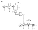
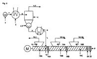
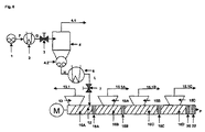
a)流体(F)を、ヒーター、脱ガス容器(4)および蒸気ラインを少なくとも含む少なくとも1つの濃縮機装置で処理し、それによって流体(F)が加熱され、加熱された流体(G)が脱ガス容器(4)へ供給され、そこで揮発性化合物の一部が、濃縮流体(H)を得るために蒸気ラインを経由して除去される工程と、
b)工程a)からの濃縮流体(H)を少なくとも1つの再加熱装置で再加熱して再加熱された濃縮流体(L)を得る工程と;
c)工程b)からの再加熱された濃縮流体(L)を、搬送セクション、1つ以上の蒸気ライン付きのガス抜き口を少なくとも含む押出機脱ガスセクションと、蓄積セクションと出口セクションとを少なくとも含む少なくとも1つの押出機装置へ供給する工程であって、少なくとも1つのストリッピング剤がさらに押出機装置に供給され、そして揮発性化合物がガス抜き口および蒸気ラインを通して除去される工程と
を少なくとも含み、
それによって再加熱された濃縮流体(L)が押出機脱ガスセクションに入る時に自由流動性であり、出口セクションで得られる水素化ニトリルゴムが揮発性化合物を実質的に含まない方法によって解決される。
This purpose is
(I) comprising repeating units derived from at least one conjugated diene, at least one α, β-unsaturated nitrile and optionally one or more copolymerizable monomers at 100 ° C. and a shear rate of 1 / sec. At least one hydrogen having a viscosity of at most 20,000 Pa * s, preferably at most 10,000 Pa * s, more preferably at most 5,000 Pa * s, most preferably at most 1,000 Pa * s Nitrile rubber,
(Ii) a method for producing a hydrogenated nitrile rubber substantially free of volatile compounds comprising the step of removing volatile compounds from a fluid (F) containing at least one volatile compound,
a) treating fluid (F) with at least one concentrator device comprising at least a heater, a degassing vessel (4) and a vapor line whereby the fluid (F) is heated and the heated fluid (G) is Fed to the degassing vessel (4), where some of the volatile compounds are removed via a steam line to obtain a concentrated fluid (H);
b) reheating the concentrated fluid (H) from step a) with at least one reheating device to obtain a reheated concentrated fluid (L);
c) the reheated concentrated fluid (L) from step b) at least in the conveying section, in the extruder degassing section comprising at least one vent with one or more vapor lines, in the accumulation section and in the outlet section Including at least one step of feeding to at least one extruder apparatus, wherein at least one stripping agent is further fed to the extruder apparatus and volatile compounds are removed through a vent and a vapor line. ,
Thereby, the reheated concentrated fluid (L) is free-flowing when entering the extruder degassing section, and the hydrogenated nitrile rubber obtained in the outlet section is solved by a process that is substantially free of volatile compounds. .
本発明の範囲はまた、各特徴について明記される好みの範囲および分野の任意の所望の組み合わせを包含することが指摘される。 It is noted that the scope of the present invention also encompasses any desired combination of preferred ranges and fields specified for each feature.
本発明との関連で用語「生成物(P)」は言及される限り、本発明による方法にかけられた後の水素化ニトリルゴムを意味するものとする。 In the context of the present invention, the term “product (P)”, as mentioned, is intended to mean a hydrogenated nitrile rubber after being subjected to the process according to the invention.
本発明との関連で、用語「自由流動性の」は、100〜50,000,000mPa*s、好ましくは500〜10,000,000mPa*s、より好ましくは5,000〜30,000,000mPa*s、最も好ましくは10,000mPa*s〜300,000mPa*sの範囲の粘度を意味する。 In the context of the present invention, the term “free-flowing” means 100 to 50,000,000 mPa * s, preferably 500 to 10,000,000 mPa * s, more preferably 5,000 to 30,000,000 mPas. * S, most preferably means a viscosity in the range of 10,000 mPa * s to 300,000 mPa * s.
そうではないと述べられない限り流体の粘度値は、Haake Rheostress RS 150粘度計または非常に粘稠な試料用のコーン−プレート型の回転流動計を用いる所与の温度での測定値から外挿されたゼロ剪断粘度を意味する。 Unless stated otherwise, fluid viscosity values are extrapolated from measurements at a given temperature using a Haake Rheoless RS 150 viscometer or a cone-plate rotary rheometer for very viscous samples. Means zero shear viscosity.
ゼロ剪断粘度へのこの外挿は典型的には次の通り実施される。すなわち、剪断応力が剪断速度に対して所与の温度で測定される。二次多項式が次に、測定から得られたデータ点に合わせられる。そのような二次多項式の直線部は、ゼロの剪断速度での勾配を反映しており、したがって本発明との関連で用いられるようなゼロ剪断粘度である。 This extrapolation to zero shear viscosity is typically performed as follows. That is, the shear stress is measured at a given temperature with respect to the shear rate. A quadratic polynomial is then fitted to the data points obtained from the measurement. The linear portion of such a second order polynomial reflects the slope at zero shear rate and is therefore zero shear viscosity as used in the context of the present invention.
水素化ニトリルゴムの粘度はまた、100℃の温度でおよび1/秒の剪断速度でHaake Rheostress RS 150粘度計またはたとえばPhysica MCR Rheometer(Anton Paar,Germany)のような同等の機器を用いて測定される。 The viscosity of the hydrogenated nitrile rubber is also measured using a Haake Rheoless RS 150 viscometer at a temperature of 100 ° C. and a shear rate of 1 / second or an equivalent instrument such as Physica MCR Rheometer (Anton Paar, Germany). The
本発明との関連で、用語「揮発性化合物を実質的に含まない」は、水素化ニトリルゴムの質量を基準として1.25重量%未満、好ましくは0.75重量%未満、より好ましくは0.5重量%未満、より好ましくは0.2重量%未満の揮発性化合物の総濃度を意味する。 In the context of the present invention, the term “substantially free of volatile compounds” means less than 1.25% by weight, preferably less than 0.75% by weight, more preferably 0, based on the mass of the hydrogenated nitrile rubber. Means a total concentration of volatile compounds of less than 5% by weight, more preferably less than 0.2% by weight.
用語「揮発性化合物を実質的に含まない」は、水を実質的に含まないおよび揮発性有機化合物を実質的に含まないことを意味する。 The term “substantially free of volatile compounds” means substantially free of water and substantially free of volatile organic compounds.
水素化ニトリルゴムは、残留水濃度が水素化ニトリルゴムの質量を基準として、0.5重量%未満、好ましくは0.25重量%未満、より好ましくは0.1重量%未満、最も好ましくは0.075重量%未満である場合に、水を実質的に含まないと考えられる。 The hydrogenated nitrile rubber has a residual water concentration of less than 0.5 wt%, preferably less than 0.25 wt%, more preferably less than 0.1 wt%, most preferably 0, based on the mass of the hydrogenated nitrile rubber. When it is less than 0.075% by weight, it is considered substantially free of water.
本発明との関連で、用語「揮発性有機化合物」は、標準圧力で250℃未満の沸点を有する有機化合物を意味する。 In the context of the present invention, the term “volatile organic compound” means an organic compound having a boiling point of less than 250 ° C. at standard pressure.
水素化ニトリルゴムは、前記揮発性有機化合物の残留濃度が水素化ニトリルゴムの質量を基準として0.75重量%未満、好ましくは0.5重量%未満、より好ましくは0.25重量%未満、最も好ましくは0.1重量%未満である場合に、揮発性有機化合物を実質的に含まないと考えられる。前記揮発性有機化合物は典型的には、HNBRへのNBRの水素化または任意の先行交差メタセシス反応に用いられた有機溶媒を含み、たとえばジクロロメタン、クロロホルム、1,2−ジクロロエタン、1,1,2−トリクロルエタン(trichlorethane)、モノクロロベンゼン、ジクロロベンゼン、トリクロロベンゼン、ベンゼン、トルエン、キシレン、メチルエチルケトン、酢酸エチル、アセトン、テトラヒドロフラン、テトラヒドロピラン、ジオキサン、およびジメチルアセトアミドからなる群から選択される水素化溶媒が挙げられる。揮発性有機化合物としてはさらに、メタセシス反応に「共オレフィン」として好ましくは添加されたオレフィンの残存する少量の水素化によって形成される、低分子量アルカン、特にn−ヘキサンが挙げられる。好ましくは本方法にかけられた後のHNBR中の揮発性有機化合物、特に有機溶媒の含有率は、2000ppm(これは水素化ニトリルゴムの質量を基準として0.2重量%である)未満、好ましくは1000ppm(これは水素化ニトリルゴムの質量を基準として0.1重量%である)未満、より好ましくは500ppm(これは水素化ニトリルゴムの質量を基準として0.05重量%である)未満である。 The hydrogenated nitrile rubber has a residual concentration of the volatile organic compound of less than 0.75% by weight, preferably less than 0.5% by weight, more preferably less than 0.25% by weight, based on the mass of the hydrogenated nitrile rubber. Most preferably, it is considered substantially free of volatile organic compounds when it is less than 0.1% by weight. The volatile organic compound typically comprises the organic solvent used in the hydrogenation of NBR to HNBR or any prior cross-metathesis reaction, such as dichloromethane, chloroform, 1,2-dichloroethane, 1,1,2 A hydrogenation solvent selected from the group consisting of trichloroethane, monochlorobenzene, dichlorobenzene, trichlorobenzene, benzene, toluene, xylene, methyl ethyl ketone, ethyl acetate, acetone, tetrahydrofuran, tetrahydropyran, dioxane, and dimethylacetamide; Can be mentioned. Volatile organic compounds further include low molecular weight alkanes, especially n-hexane, which are formed by a small amount of remaining hydrogenation of the olefin preferably added as a “co-olefin” to the metathesis reaction. Preferably the content of volatile organic compounds, in particular organic solvents, in the HNBR after being subjected to the process is less than 2000 ppm (which is 0.2% by weight, based on the mass of the hydrogenated nitrile rubber), preferably Less than 1000 ppm (this is 0.1 wt% based on the mass of the hydrogenated nitrile rubber), more preferably less than 500 ppm (this is 0.05 wt% based on the mass of the hydrogenated nitrile rubber) .
揮発性化合物を測定する方法、たとえば乾燥工程前後の水素化ニトリルゴム試料の重量差を測定する方法は、当業者によく知られている。水とより高沸点の有機溶媒を除いた揮発性有機化合物とを包含する揮発性化合物は、5gの水素化ニトリルゴム試料を一定の重量まで105℃でのIR放射によってアルミニウムボウル中で乾燥させることによって。そのような測定のために用いられる機器、たとえばMettlerのIR scale HR73は商業的に入手可能である。水とより高沸点の有機溶媒を除いた揮発性有機化合物を包含する揮発性化合物との量は次に、IR放射乾燥前後の重量差として得られる。 Methods for measuring volatile compounds, such as measuring the weight difference between hydrogenated nitrile rubber samples before and after the drying step, are well known to those skilled in the art. Volatile compounds, including water and volatile organic compounds excluding higher boiling organic solvents, dry 5 g hydrogenated nitrile rubber samples in an aluminum bowl by IR radiation at 105 ° C. to constant weight. By. Instruments used for such measurements, such as Mettler's IR scale HR73, are commercially available. The amount of water and volatile compounds including volatile organic compounds excluding higher boiling organic solvents is then obtained as the weight difference before and after IR radiation drying.
前述のIR放射乾燥によって測定されないより高沸点の有機溶媒の量は、ガスクロマトグラフィーによって測定されてもよい。実行可能な手順は、NBR水素化の好ましい溶媒としてのモノクロロベンゼンの測定について本明細書で以下に記載される:2.5gのHNBR試料がトウモロコシの粒子のサイズにカットされ、100mlの密封可能な容器に±1mgの精度で秤量され、その後25mlのアセトンに撹拌下に室温で溶解される(継続時間は典型的には2〜3時間)。2mlアセトンに溶解された少量の規定量の1,2−ジクロロベンゼンが次に内部標準として添加される。HNBRは次に、40mlのメタノールを加えることによって凝固させられる。その後容器は100mlまでメタノールで満たされる。モノクロロベンゼンの量は次に、シリカ・キャピラリーカラム(Hewlett Packard(現Agilent)製のHP 1)および水素炎イオン化検出器のHewlett Packard chromatograph HP 5890 IIを用いるガスクロマトグラフィーによって測定される。キャピラリーカラムは、次の特性:長さ:25m、径:0.32mm;コーティング:ポリジメチルシロキサン、コーティング厚さ:1.05μmで特徴づけられる。測定目的のためには、凝固したHNBRが除去された5mlの前述の溶液が270℃の温度でのガスクロマトグラフへ注入される。水素が2ml/分の流量でキャリアガスとして使用される。カラムの温度は60℃の出発温度を有し、110℃まで10℃/分で、その後310℃まで25℃/分で上げられる。カラムは次に310℃の温度で8分間保たれる。前述の条件を適用すると、2,364および5,294分のモノクロロベンゼンおよび1,2−ジクロロベンゼンの保持時間をもたらす。モノクロロベンゼンを定量的に測定するために規定のモノクロロベンゼンおよび1,2−ジクロロベンゼン量の面積比が独立した測定で求められる。 The amount of higher boiling organic solvent not measured by IR radiation drying as described above may be measured by gas chromatography. A feasible procedure is described herein below for the measurement of monochlorobenzene as the preferred solvent for NBR hydrogenation: 2.5 g of HNBR sample is cut to corn particle size and 100 ml of sealable It is weighed in a container with an accuracy of ± 1 mg and then dissolved in 25 ml of acetone with stirring at room temperature (duration typically is 2-3 hours). A small defined amount of 1,2-dichlorobenzene dissolved in 2 ml acetone is then added as an internal standard. The HNBR is then coagulated by adding 40 ml of methanol. The vessel is then filled with methanol up to 100 ml. The amount of monochlorobenzene is then measured by gas chromatography using a silica capillary column (Hewlett Packard (now Agilent) HP 1) and a flame ionization detector Hewlett Packard chromatograph HP 5890 II. The capillary column is characterized by the following properties: length: 25 m, diameter: 0.32 mm; coating: polydimethylsiloxane, coating thickness: 1.05 μm. For measurement purposes, 5 ml of the above solution from which the coagulated HNBR has been removed is injected into a gas chromatograph at a temperature of 270 ° C. Hydrogen is used as a carrier gas at a flow rate of 2 ml / min. The column temperature has a starting temperature of 60 ° C. and is raised to 110 ° C. at 10 ° C./min and then to 310 ° C. at 25 ° C./min. The column is then held at a temperature of 310 ° C. for 8 minutes. Application of the aforementioned conditions results in retention times of monochlorobenzene and 1,2-dichlorobenzene of 2,364 and 5,294 minutes. In order to quantitatively measure monochlorobenzene, the area ratio of the specified monochlorobenzene and 1,2-dichlorobenzene amounts is determined by independent measurement.
本発明による方法によって得られる水素化ニトリルゴムは、揮発性化合物の濃度がそれほど低いという点において公知のおよび今まで商業的に入手可能な任意の水素化ニトリルゴムから区別される。本発明の方法は、先行技術の方法が並外れた生成物損失をもたらすのに対して向上した収率をもたらすので、水素化ニトリルゴム、特により低い粘度のものを単離するために今まで公知の方法より明らかに優れている。 The hydrogenated nitrile rubber obtained by the process according to the invention is distinguished from any known and commercially available hydrogenated nitrile rubber in that the concentration of volatile compounds is so low. The process of the present invention has hitherto been known for isolating hydrogenated nitrile rubbers, particularly those of lower viscosity, as the prior art processes provide improved yields while providing exceptional product losses. It is clearly better than the method.
本発明による方法にかけられる水素化ニトリルゴム:
本発明による方法は、少なくとも1つの共役ジエン、少なくとも1つのα,β−不飽和ニトリルおよび、必要ならば、1つ以上のさらなる共重合性モノマーに由来する繰り返し単位を含む水素化ニトリルゴム、すなわち最大でも20,000Pa*s(100℃および1/秒の剪断速度で測定される)、好ましくは最大でも10,000Pa*s、より好ましくは最大でも5,000Pa*s、最も好ましくは最大でも1,000Pa*sの粘度を有するコポリマーかターポリマーかのどちらかを出発ゴムとして使用する。
Hydrogenated nitrile rubber subjected to the process according to the invention:
The process according to the invention comprises a hydrogenated nitrile rubber comprising at least one conjugated diene, at least one α, β-unsaturated nitrile and, if necessary, repeating units derived from one or more further copolymerizable monomers, At most 20,000 Pa * s (measured at 100 ° C. and 1 / sec shear rate), preferably at most 10,000 Pa * s, more preferably at most 5,000 Pa * s, most preferably at most 1 Either a copolymer or a terpolymer having a viscosity of 1,000 Pa * s is used as the starting rubber.
用語「に由来する」は、共役ジエンの繰り返し単位の場合に炭素−炭素二重結合が部分的にまたは完全に水素化されていることを意味するものとする。水素化ニトリルゴムは、相当するニトリルゴムを水素化することによって得られる。 The term “derived from” shall mean that in the case of repeating units of conjugated dienes, the carbon-carbon double bonds are partially or fully hydrogenated. Hydrogenated nitrile rubber is obtained by hydrogenating the corresponding nitrile rubber.
共役ジエンは、任意の性質のものであることができる。(C4〜C6)共役ジエンを使用することが好ましい。1,3−ブタジエン、イソプレン、2,3−ジメチルブタジエン、ピペリレンまたはそれらの混合物が特に好ましい。1,3−ブタジエンおよびイソプレンまたはそれらの混合物が非常に特に好ましい。1,3−ブタジエンがとりわけ好ましい。 The conjugated diene can be of any nature. It is preferred to use (C 4 -C 6 ) conjugated dienes. 1,3-butadiene, isoprene, 2,3-dimethylbutadiene, piperylene or mixtures thereof are particularly preferred. Very particular preference is given to 1,3-butadiene and isoprene or mixtures thereof. 1,3-butadiene is particularly preferred.
α,β−不飽和ニトリルとして、任意の公知のα,β−不飽和ニトリル、好ましくはアクリロニトリル、メタクリロニトリル、エタクリロニトリルまたはそれらの混合物などの(C3〜C5)α,β−不飽和ニトリルを使用することが可能である。アクリロニトリルが特に好ましい。 As the α, β-unsaturated nitrile, any known α, β-unsaturated nitrile, preferably (C 3 -C 5 ) α, β-unsaturated, such as acrylonitrile, methacrylonitrile, ethacrylonitrile or mixtures thereof. Saturated nitriles can be used. Acrylonitrile is particularly preferred.
特に好ましい水素化ニトリルゴムはしたがって、アクリロニトリルおよび1,3−ブタジエンに由来する繰り返し単位を有するコポリマーである。 Particularly preferred hydrogenated nitrile rubbers are therefore copolymers having repeating units derived from acrylonitrile and 1,3-butadiene.
共役ジエンおよびα,β−不飽和ニトリルは別として、水素化ニトリルゴムは、当該技術分野において公知の1つ以上のさらなる共重合性モノマー、たとえばα,β−不飽和(好ましくはモノ不飽和)モノカルボン酸、それらのエステルおよびアミド、α,β−不飽和(好ましくはモノ不飽和)ジカルボン酸、それらのモノ−もしくはジエステル、ならびに前記α,β−不飽和ジカルボン酸のそれぞれの酸無水物またはアミドの繰り返し単位を含んでもよい。 Apart from conjugated dienes and α, β-unsaturated nitriles, hydrogenated nitrile rubbers are one or more additional copolymerizable monomers known in the art, such as α, β-unsaturated (preferably monounsaturated). Monocarboxylic acids, their esters and amides, α, β-unsaturated (preferably monounsaturated) dicarboxylic acids, their mono- or diesters and the respective acid anhydrides of said α, β-unsaturated dicarboxylic acids or It may contain amide repeating units.
α,β−不飽和モノカルボン酸としてアクリル酸およびメタクリル酸が好ましくは使用される。 Acrylic acid and methacrylic acid are preferably used as the α, β-unsaturated monocarboxylic acid.
α,β−不飽和モノカルボン酸のエステル、特にアルキルエステル、アルコキシアルキルエステル、アリールエステル、シクロアルキルエステル、シアノアルキルエステル、ヒドロキシアルキルエステル、およびフルオロアルキルエステルが使用されてもよい。 Esters of α, β-unsaturated monocarboxylic acids, particularly alkyl esters, alkoxyalkyl esters, aryl esters, cycloalkyl esters, cyanoalkyl esters, hydroxyalkyl esters, and fluoroalkyl esters may be used.
アルキルエステルとしてα,β−不飽和モノカルボン酸のC1〜C18アルキルエステルが好ましくは使用され、より好ましくはメチルアクリレート、エチルアクリレート、プロピルアクリレート、n−ブチルアクリレート、tert−ブチルアクリレート、2−エチルヘキシルアクリレート、n−ドデシルアクリレート、メチルメタクリレート、エチルメタクリレート、プロピルメタクリレート、n−ブチルメタクリレート、tert−ブチルメタクリレートおよび2−エチルヘキシル−メタクリレートなどの、アクリル酸またはメタクリル酸のC1〜C18アルキルエステルが使用される。 C 1 -C 18 alkyl esters of α, β-unsaturated monocarboxylic acids are preferably used as alkyl esters, more preferably methyl acrylate, ethyl acrylate, propyl acrylate, n-butyl acrylate, tert-butyl acrylate, 2- Use C 1 -C 18 alkyl esters of acrylic acid or methacrylic acid, such as ethylhexyl acrylate, n-dodecyl acrylate, methyl methacrylate, ethyl methacrylate, propyl methacrylate, n-butyl methacrylate, tert-butyl methacrylate and 2-ethylhexyl methacrylate Is done.
アルコキシアルキルエステルとしてα,β−不飽和モノカルボン酸のC2〜C18アルコキシアルキルエステルが好ましくは使用され、より好ましくはメトキシメチル(メタ)アクリレート、メトキシエチル(メタ)アクリレート、エトキシエチル(メタ)アクリレートおよびメトキシエチル(メタ)アクリレートなどのアクリル酸またはメタクリル酸のアルコキシアルキルエステルが使用される。 As alkoxyalkyl esters α, β- C 2 ~C 18 alkoxyalkyl esters of unsaturated monocarboxylic acids is preferably used, more preferably methoxymethyl (meth) acrylate, methoxyethyl (meth) acrylate, ethoxyethyl (meth) Alkoxyalkyl esters of acrylic or methacrylic acid such as acrylate and methoxyethyl (meth) acrylate are used.
アリールエステル、好ましくはC6〜C14アリール−、より好ましくはC6〜C10アリールエステル、最も好ましくはアクリレートおよびメタクリレートの前述のアリールエステルを使用することもまた可能である。 It is also possible to use aryl esters, preferably C 6 -C 14 aryl-, more preferably C 6 -C 10 aryl esters, most preferably the aforementioned aryl esters of acrylates and methacrylates.
別の実施形態においてはシクロアルキルエステル、好ましくはC5〜C12シクロアルキル−、より好ましくはC6〜C12シクロアルキル、最も好ましくは前述のシクロアルキルアクリレートおよびメタクリレートが使用される。 In another embodiment, cycloalkyl esters, preferably C 5 -C 12 cycloalkyl-, more preferably C 6 -C 12 cycloalkyl, most preferably the aforementioned cycloalkyl acrylates and methacrylates are used.
シアノアルキル基中のC原子の数が2〜12の範囲にある、シアノアルキルエステル、特にシアノアルキルアクリレートまたはシアノアルキルメタクリレートを使用することもまた可能であり、好ましくはα−シアノエチルアクリレート、β−シアノエチルアクリレートまたはシアノブチルメタクリレートが使用される。 It is also possible to use cyanoalkyl esters, in particular cyanoalkyl acrylates or cyanoalkyl methacrylates, in which the number of C atoms in the cyanoalkyl group ranges from 2 to 12, preferably α-cyanoethyl acrylate, β-cyanoethyl. Acrylate or cyanobutyl methacrylate is used.
別の実施形態においてはヒドロキシアルキルエステル、特に、ヒドロキシルアルキル基中のC原子の数が1〜12の範囲にあるヒドロキシアルキルアクリレートおよびヒドロキシアルキルメタクリレート、好ましくは2−ヒドロキシエチルアクリレート、2−ヒドロキシエチルメタクリレートまたは3−ヒドロキシプロピルアクリレートが使用される。 In another embodiment hydroxyalkyl esters, in particular hydroxyalkyl acrylates and hydroxyalkyl methacrylates in which the number of C atoms in the hydroxylalkyl group is in the range of 1 to 12, preferably 2-hydroxyethyl acrylate, 2-hydroxyethyl methacrylate Or 3-hydroxypropyl acrylate is used.
フルオロベンジルエステル、特にフルオロベンジルアクリレートまたはフルオロベンジルメタクリレート、好ましくはトリフルオロエチルアクリレートおよびテトラフルオロプロピルメタクリレートを使用することもまた可能である。ジメチルアミノメチルアクリレートおよびジエチルアミノエチルアクリレートのような置換アミノ基を含有するアクリレートおよびメタクリレートがまた使用されてもよい。 It is also possible to use fluorobenzyl esters, in particular fluorobenzyl acrylate or fluorobenzyl methacrylate, preferably trifluoroethyl acrylate and tetrafluoropropyl methacrylate. Acrylates and methacrylates containing substituted amino groups such as dimethylaminomethyl acrylate and diethylaminoethyl acrylate may also be used.
たとえばポリエチレングリコール(メタ)アクリレート、ポリプロピレングリコール(メタ)アクリレート、グリシジル(メタ)アクリレート、エポキシ(メタ)アクリレート、N−(2−ヒドロキシエチル)アクリルアミド、N−(2−ヒドロキシメチル)アクリルアミドまたはウレタン(メタ)アクリレートのような、α,β−不飽和カルボン酸の様々なその他のエステルがまた使用されてもよい。 For example, polyethylene glycol (meth) acrylate, polypropylene glycol (meth) acrylate, glycidyl (meth) acrylate, epoxy (meth) acrylate, N- (2-hydroxyethyl) acrylamide, N- (2-hydroxymethyl) acrylamide or urethane (meth) ) Various other esters of α, β-unsaturated carboxylic acids, such as acrylates, may also be used.
α,β−不飽和カルボン酸のすべての前述のエステルの混合物を使用することもまた可能である。 It is also possible to use mixtures of all the aforementioned esters of α, β-unsaturated carboxylic acids.
さらなるα,β−不飽和ジカルボン酸、好ましくはマレイン酸、フマル酸、クロトン酸、イタコン酸、シトラコン酸およびメサコン酸が使用されてもよい。 Further α, β-unsaturated dicarboxylic acids may be used, preferably maleic acid, fumaric acid, crotonic acid, itaconic acid, citraconic acid and mesaconic acid.
別の実施形態においてα,β−不飽和ジカルボン酸の無水物、好ましくは無水マレイン酸、無水イタコン酸、無水イタコン酸、無水シトラコン酸および無水メサコン酸が使用される。 In another embodiment, an anhydride of α, β-unsaturated dicarboxylic acid is used, preferably maleic anhydride, itaconic anhydride, itaconic anhydride, citraconic anhydride and mesaconic anhydride.
さらなる実施形態においてはα,β−不飽和ジカルボン酸のモノ−またはジエステルを使用することができる。好適なアルキルエステルは、たとえばC1〜C10アルキル、好ましくはエチル−、n−プロピル−、イソ−プロピル、n−ブチル−、tert−ブチル、n−ペンチル−またはn−ヘキシルモノ−またはたジエステルである。好適なアルコキシアルキルエステルは、たとえばC2〜C12アルコキシアルキル−、好ましくはC3〜C8アルコキシアルキルモノ−またはジエステルである。好適なヒドロキシアルキルエステルは、たとえばC1〜C12ヒドロキシアルキル−、好ましくはC2〜C8ヒドロキシアルキルモノ−またはジエステルである。好適なシクロアルキルエステルは、たとえばC5〜C12シクロアルキル−、好ましくはC6〜C12シクロアルキルモノ−またはジエステルである。好適なアルキルシクロアルキルエステルは、たとえばC6〜C12アルキルシクロアルキル−、好ましくはC7〜C10アルキルシクロアルキルモノ−またはジエステルである。好適なアリールエステルは、たとえばC6〜C14アリール、好ましくはC6〜C10アリールモノ−またはジエステルである。 In further embodiments, mono- or diesters of α, β-unsaturated dicarboxylic acids can be used. Suitable alkyl esters are, for example, C 1 -C 10 alkyl, preferably ethyl-, n-propyl-, iso-propyl, n-butyl-, tert-butyl, n-pentyl- or n-hexyl mono- or diester. is there. Suitable alkoxyalkyl esters are, for example, C 2 -C 12 alkoxyalkyl-, preferably C 3 -C 8 alkoxyalkyl mono- or diesters. Suitable hydroxyalkyl esters are, for example, C 1 -C 12 hydroxyalkyl-, preferably C 2 -C 8 hydroxyalkyl mono- or diesters. Suitable cycloalkyl esters are, for example, C 5 -C 12 cycloalkyl-, preferably C 6 -C 12 cycloalkyl mono- or diesters. Suitable alkylcycloalkyl esters, for example C 6 -C 12 alkylcycloalkyl - or diesters -, preferably C 7 -C 10 alkylcycloalkyl things. Suitable aryl esters are, for example, C 6 -C 14 aryl, preferably C 6 -C 10 aryl mono- or diesters.
α,β−エチレン系不飽和ジカルボン酸モノエステルモノマーの明白な例としては、
・マレイン酸モノアルキルエステル、好ましくはモノメチルマレエート、モノエチルマレエート、モノプロピルマレエート、およびモノn−ブチルマレエート;
・マレイン酸モノシクロアルキルエステル、好ましくはモノシクロペンチルマレエート、モノシクロヘキシルマレエート、およびモノシクロヘプチルマレエート;
・マレイン酸モノアルキルシクロアルキルエステル、好ましくはモノメチルシクロペンチルマレエート、およびモノエチルシクロヘキシルマレエート;
・マレイン酸モノアリールエステル、好ましくはモノフェニルマレエート;
・マレイン酸モノベンジルエステル、好ましくはモノベンジルマレエート;
・フマル酸モノアルキルエステル、好ましくはモノメチルフマレート、モノエチルフマレート、モノプロピルフマレート、およびモノn−ブチルフマレート;
・フマル酸モノシクロアルキルエステル、好ましくはモノシクロペンチルフマレート、モノシクロヘキシルフマレート、およびモノシクロヘプチルフマレート;
・フマル酸モノアルキルシクロアルキルエステル、好ましくはモノメチルシクロペンチルフマレート、およびモノエチルシクロヘキシルフマレート;
・フマル酸モノアリールエステル、好ましくはモノフェニルフマレート;
・フマル酸モノベンジルエステル、好ましくはモノベンジルフマレート;
・シトラコン酸モノアルキルエステル、好ましくはモノメチルシトラコネート、モノエチルシトラコネート、モノプロピルシトラコネート、およびモノn−ブチルシトラコネート;
・シトラコン酸モノシクロアルキルエステル、好ましくはモノシクロペンチルシトラコネート、モノシクロヘキシルシトラコネート、およびモノシクロヘプチルシトラコネート;
・シトラコン酸モノアルキルシクロアルキルエステル、好ましくはモノメチルシクロペンチルシトラコネート、およびモノエチルシクロヘキシルシトラコネート;
・シトラコン酸モノアリールエステル、好ましくはモノフェニルシトラコネート;
・シトラコン酸モノベンジルエステル、好ましくはモノベンジルシトラコネート;
・イタコン酸モノアルキルエステル、好ましくはモノメチルイタコネート、モノエチルイタコネート、モノプロピルイタコネート、およびモノn−ブチルイタコネート;
・イタコン酸モノシクロアルキルエステル、好ましくはモノシクロペンチルイタコネート、モノシクロヘキシルイタコネート、およびモノシクロヘプチルイタコネート;
・イタコン酸モノアルキルシクロアルキルエステル、好ましくはモノメチルシクロペンチルイタコネート、およびモノエチルシクロヘキシルイタコネート;
・イタコン酸モノアリールエステル、好ましくはモノフェニルイタコネート;
・イタコン酸モノベンジルエステル、好ましくはモノベンジルイタコネート
が挙げられる。
Clear examples of α, β-ethylenically unsaturated dicarboxylic acid monoester monomers include:
Maleic acid monoalkyl esters, preferably monomethyl maleate, monoethyl maleate, monopropyl maleate, and mono n-butyl maleate;
Maleic acid monocycloalkyl esters, preferably monocyclopentyl maleate, monocyclohexyl maleate, and monocycloheptyl maleate;
Maleic monoalkyl cycloalkyl esters, preferably monomethylcyclopentyl maleate, and monoethyl cyclohexyl maleate;
Maleic acid monoaryl esters, preferably monophenyl maleate;
Maleic acid monobenzyl ester, preferably monobenzyl maleate;
A fumaric acid monoalkyl ester, preferably monomethyl fumarate, monoethyl fumarate, monopropyl fumarate, and mono n-butyl fumarate;
A monocycloalkyl ester of fumaric acid, preferably monocyclopentyl fumarate, monocyclohexyl fumarate, and monocycloheptyl fumarate;
A monoalkyl cycloalkyl ester of fumaric acid, preferably monomethylcyclopentyl fumarate, and monoethylcyclohexyl fumarate;
A monoaryl ester of fumaric acid, preferably monophenyl fumarate;
-Fumaric acid monobenzyl ester, preferably monobenzyl fumarate;
Citraconic acid monoalkyl esters, preferably monomethylcitraconate, monoethylcitraconate, monopropylcitraconate, and mono n-butylcitraconate;
Citraconic acid monocycloalkyl esters, preferably monocyclopentyl citraconate, monocyclohexyl citraconate, and monocycloheptyl citraconate;
Citraconic acid monoalkyl cycloalkyl esters, preferably monomethylcyclopentyl citraconate, and monoethylcyclohexyl citraconate;
Citraconic acid monoaryl esters, preferably monophenylcitraconate;
Citraconic acid monobenzyl ester, preferably monobenzyl citraconic acid;
Itaconic acid monoalkyl esters, preferably monomethyl itaconate, monoethyl itaconate, monopropyl itaconate, and mono n-butyl itaconate;
Itaconic acid monocycloalkyl esters, preferably monocyclopentyl itaconate, monocyclohexyl leuconconate, and monocycloheptyl leuconate;
Itaconic acid monoalkyl cycloalkyl esters, preferably monomethylcyclopentyl itaconate, and monoethyl cyclohexyl lutaconate;
Itaconic acid monoaryl ester, preferably monophenyl itaconate;
-Itaconic acid monobenzyl ester, Preferably monobenzyl itaconate is mentioned.
α,β−エチレン系不飽和ジカルボン酸ジエステルモノマーとして、上に明白に述べられたモノエステルモノマーをベースとする類似のジエステルが、ここで使用されてもよいが、酸素原子を介してC=O基に結合した2つの有機基は同一であっても異なってもよい。 As α, β-ethylenically unsaturated dicarboxylic acid diester monomers, similar diesters based on the monoester monomers explicitly mentioned above may be used here, but via the oxygen atom C═O The two organic groups bonded to the group may be the same or different.
さらなるターモノマーとして、スチロール、α−メチルスチロールおよびビニルピリジンのようなビニル芳香族モノマー、ならびに4−シアノシクロヘキセンおよび4−ビニルシクロヘキセンのような非共役ジエン、ならびに1−もしくは2−ブチンのようなアルキンが使用されてもよい。 Further termonomers include vinyl aromatic monomers such as styrene, α-methyl styrene and vinyl pyridine, and non-conjugated dienes such as 4-cyanocyclohexene and 4-vinylcyclohexene, and alkynes such as 1- or 2-butyne. May be used.
使用されるHNBRポリマー中の共役ジエンおよびα,β−不飽和ニトリルの割合は、広範囲内で変わることができる。共役ジエンのまたは共役ジエンの合計の割合は、全ポリマーを基準として、通常40〜90重量%の範囲に、好ましくは50〜85重量%の範囲にある。α,β−不飽和ニトリルのまたはα,β−不飽和ニトリルの合計の割合は、全ポリマーを基準として、通常10〜60重量%、好ましくは15〜50重量%の範囲にある。モノマーの割合は各場合に合計して100重量%になる。追加のモノマーは、全ポリマーを基準として、0〜40重量%、好ましくは0.1〜40重量%、特に好ましくは1〜30重量%の量で存在することができる。この場合に、1つまたは複数の共役ジエンおよび/または1つまたは複数のα,β−不飽和ニトリルの相当する割合は、各場合にすべてのモノマーの割合が合計して100重量%になる状態で、追加のモノマーの割合で置き換えられる。 The proportion of conjugated diene and α, β-unsaturated nitrile in the HNBR polymer used can vary within wide limits. The proportion of conjugated dienes or the total of conjugated dienes is usually in the range of 40 to 90% by weight, preferably in the range of 50 to 85% by weight, based on the total polymer. The total proportion of α, β-unsaturated nitrile or α, β-unsaturated nitrile is usually in the range of 10 to 60% by weight, preferably 15 to 50% by weight, based on the total polymer. The proportion of monomers is 100% by weight in each case. The additional monomer can be present in an amount of 0 to 40% by weight, preferably 0.1 to 40% by weight, particularly preferably 1 to 30% by weight, based on the total polymer. In this case, the corresponding proportion of one or more conjugated dienes and / or one or more α, β-unsaturated nitriles is such that the proportion of all monomers in each case is 100% by weight. Is replaced by the proportion of additional monomer.
具体的な一実施形態において水素化ニトリルゴムは、本方法にかけられてもよく、ここでα,β−不飽和ニトリルに由来する繰り返し単位の割合は、全水素化ニトリルゴムを基準として43重量%超、好ましくは44.5重量%超および60重量%以下、より好ましくは44.5重量%超および52重量%以下であり、最も好ましくは45〜50.5重量%の範囲にある。それ故に、共役ジエンのまたは共役ジエンの合計の割合はそのような場合に、全ポリマーを基準として57重量%以下、好ましくは40〜55.5重量%の範囲に、より好ましくは48〜55.5重量%の範囲に、最も好ましくは49.5〜55重量%の範囲にある。 In one specific embodiment, the hydrogenated nitrile rubber may be subjected to the present process, wherein the proportion of repeating units derived from the α, β-unsaturated nitrile is 43% by weight based on the total hydrogenated nitrile rubber. More than, preferably more than 44.5% and not more than 60%, more preferably more than 44.5% and not more than 52%, most preferably in the range of 45-50.5% by weight. Therefore, the proportion of conjugated dienes or the total of conjugated dienes in such cases is not more than 57% by weight, preferably in the range of 40-55.5% by weight, more preferably in the range of 48-55.5%, based on the total polymer. It is in the range of 5% by weight, most preferably in the range of 49.5% to 55% by weight.
本発明による方法にかけられる水素化ニトリルゴムの製造:
流体(F)に含有される、最大でも20,000Pa*s(100℃および1/秒の剪断速度で測定される)、好ましくは最大でも10,000Pa*s、より好ましくは最大でも5,000Pa*s、最も好ましくは最大でも1,000Pa*sの粘度を有する水素化ニトリルゴムは典型的には、
1)少なくとも1つの共役ジエン、少なくとも1つのα,β−不飽和ニトリルおよび任意選択的に1つ以上のさらなる共重合性モノマーを重合させてニトリルゴムを得る工程と、
2)工程1)のニトリルゴムを、任意選択的に低分子量1−オレフィンの存在下に接触メタセシス反応にかけてニトリルゴムの分子量を低下させる工程と
3)工程2)において得られたニトリルゴムを、有機溶媒である揮発性化合物中で水素化反応にかけて所望の水素化ニトリルゴムおよび揮発性化合物を含む流体(F)をもたらす工程と
によって製造される。
Production of hydrogenated nitrile rubber subjected to the process according to the invention:
At most 20,000 Pa * s (measured at 100 ° C. and 1 / sec shear rate), preferably at most 10,000 Pa * s, more preferably at most 5,000 Pa, contained in the fluid (F) Hydrogenated nitrile rubber having a viscosity of * s, most preferably at most 1,000 Pa * s is typically
1) polymerizing at least one conjugated diene, at least one α, β-unsaturated nitrile and optionally one or more further copolymerizable monomers to obtain a nitrile rubber;
2) a step of reducing the molecular weight of the nitrile rubber by optionally subjecting the nitrile rubber of step 1) to a catalytic metathesis reaction in the presence of a low molecular weight 1-olefin; and 3) the nitrile rubber obtained in step 2) In a volatile compound that is a solvent to produce a fluid (F) containing a desired hydrogenated nitrile rubber and a volatile compound through a hydrogenation reaction.
それ故に、最大でも20,000Pa*s(100℃および1/秒の剪断速度で測定される)、好ましくは最大でも10,000Pa*s、より好ましくは最大でも5,000Pa*s、最も好ましくは最大でも1,000Pa*sの粘度を有し、揮発性化合物を実質的に含まない水素化ニトリルゴムは、少なくとも次の工程
1)少なくとも1つの共役ジエン、少なくとも1つのα,β−不飽和ニトリルおよび任意選択的に1つ以上のさらなる共重合性モノマーを重合させてニトリルゴムを得る工程と、
2)工程1)のニトリルゴムを、任意選択的に低分子量1−オレフィンの存在下に接触メタセシス反応にかけてニトリルゴムの分子量を低下させる工程と
3)工程2)のニトリルゴムを、有機溶媒である揮発性化合物中で水素化反応にかけて最大でも20,000Pa*s(100℃および1/秒の剪断速度で測定される)、好ましくは最大でも10,000Pa*s、より好ましくは最大でも5,000Pa*s、最も好ましくは最大でも1,000Pa*sの粘度を有する水素化ニトリルゴムおよび少なくとも1つの揮発性化合物を含む流体(F)をもたらす工程と、
4)a)流体(F)を、ヒーター、脱ガス容器(4)および蒸気ラインを少なくとも含む少なくとも1つの濃縮機装置で処理し、それによって流体(F)が加熱され、加熱された流体(G)が脱ガス容器(4)へ供給され、そこで揮発性化合物の一部が、濃縮流体(H)を得るために蒸気ラインを経由して除去される工程、
b)工程a)からの濃縮流体(H)を少なくとも1つの再加熱装置で再加熱して再加熱された濃縮流体(L)を得る工程;および
c)工程b)からの再加熱された濃縮流体(L)を、搬送セクション、1つ以上の蒸気ライン付きのガス抜き口を少なくとも含む押出機脱ガスセクションと、蓄積セクションと出口セクションとを少なくとも含む少なくとも1つの押出機装置へ供給する工程であって、ストリッピング剤がさらに押出機装置に供給され、そして揮発性化合物がガス抜き口および蒸気ラインを通して除去される工程
を少なくとも含むプロセスによって揮発性化合物を流体(F)から除去する工程と
によって製造することができ、
それによって再加熱された濃縮流体(L)は押出機脱ガスセクションに入る時に自由流動性であり、出口セクションで得られる水素化ニトリルゴムは揮発性化合物を実質的に含まない。
Therefore, at most 20,000 Pa * s (measured at 100 ° C. and 1 / sec shear rate), preferably at most 10,000 Pa * s, more preferably at most 5,000 Pa * s, most preferably Hydrogenated nitrile rubber having a viscosity of at most 1,000 Pa * s and substantially free of volatile compounds is at least the following step 1) at least one conjugated diene, at least one α, β-unsaturated nitrile And optionally polymerizing one or more further copolymerizable monomers to obtain a nitrile rubber;
2) a step of reducing the molecular weight of the nitrile rubber by optionally subjecting the nitrile rubber of step 1) to a catalytic metathesis reaction in the presence of a low molecular weight 1-olefin; and 3) the nitrile rubber of step 2) is an organic solvent. Up to 20,000 Pa * s (measured at 100 ° C. and 1 / sec shear rate), preferably at most 10,000 Pa * s, more preferably at most 5,000 Pa over the hydrogenation reaction in volatile compounds. Providing a fluid (F) comprising hydrogenated nitrile rubber having a viscosity of * s, most preferably at most 1,000 Pa * s and at least one volatile compound;
4) a) Fluid (F) is treated with at least one concentrator device comprising at least a heater, a degassing vessel (4) and a vapor line whereby the fluid (F) is heated and heated fluid (G ) Is supplied to the degassing vessel (4), where some of the volatile compounds are removed via a vapor line to obtain a concentrated fluid (H),
b) reheating the concentrated fluid (H) from step a) with at least one reheating device to obtain a reheated concentrated fluid (L); and c) reheated concentration from step b). Supplying fluid (L) to at least one extruder apparatus comprising at least a conveying section, an extruder degassing section including at least one vent with one or more steam lines, and an accumulation section and an outlet section; Removing the volatile compounds from the fluid (F) by a process comprising at least a step wherein stripping agent is further fed to the extruder apparatus and the volatile compounds are removed through the vent and vapor line. Can be manufactured,
The concentrated fluid (L) reheated thereby is free-flowing upon entering the extruder degassing section, and the hydrogenated nitrile rubber obtained in the outlet section is substantially free of volatile compounds.
好ましい一実施形態において本発明の方法によって得られた、揮発性化合物を実質的に含まない水素化ニトリルゴムは、少なくとも1つの共役ジエン、少なくとも1つのα,β−不飽和ニトリルおよび任意選択的に1つ以上の共重合性モノマーに由来する繰り返し単位を含み、最大でも20,000Pa*s(100℃および1/秒の剪断速度で測定される)、好ましくは最大でも10,000Pa*s、より好ましくは最大でも5,000Pa*s、最も好ましくは最大でも1,000Pa*sの粘度を有し、50,000g/モル以下、好ましくは10,000〜50,000g/モル、より好ましくは12,000〜40,000g/モルの重量平均分子量Mwおよび2.0未満の多分散性(Mw/Mn)を有する。そのような好ましいグレードについては、これらのタイプが蜂蜜様外観を有し、そしてムーニー粘度が5ムーニー単位未満の値については測定されない可能性があるので、ムーニー粘度を測定することはもはや可能ではない。 In one preferred embodiment, the hydrogenated nitrile rubber substantially free of volatile compounds obtained by the process of the invention comprises at least one conjugated diene, at least one α, β-unsaturated nitrile and optionally Containing repeating units derived from one or more copolymerizable monomers, at most 20,000 Pa * s (measured at 100 ° C. and 1 / sec shear rate), preferably at most 10,000 Pa * s, and more Preferably, it has a viscosity of at most 5,000 Pa * s, most preferably at most 1,000 Pa * s, and is 50,000 g / mol or less, preferably 10,000 to 50,000 g / mol, more preferably 12, It has a weight average molecular weight Mw of 000 to 40,000 g / mol and a polydispersity (Mw / Mn) of less than 2.0. For such preferred grades, it is no longer possible to measure Mooney viscosity because these types have a honey-like appearance and Mooney viscosity may not be measured for values below 5 Mooney units. .
別の好ましい実施形態において本発明の方法によって得られた、揮発性化合物を実質的に含まない水素化ニトリルゴムは、少なくとも1つの共役ジエン、少なくとも1つのα,β−不飽和ニトリルおよび任意選択的に1つ以上の共重合性モノマーに由来する繰り返し単位を含み、最大でも20,000Pa*s(100℃および1/秒の剪断速度で測定される)、好ましくは最大でも10,000Pa*s、より好ましくは最大でも5,000Pa*s、最も好ましくは最大でも1,000Pa*sの粘度、および50,000g/モル超である、好ましくは50,000〜250,000の範囲にある重量平均の分子量を有し、多分散性は、2.1〜3.0、好ましくは2.1〜3未満、より好ましくは2.2〜2.9、さらにより好ましくは2.3〜2.9、最も好ましくは2.4〜2.8の範囲にある。 In another preferred embodiment, the hydrogenated nitrile rubber substantially free of volatile compounds obtained by the method of the present invention comprises at least one conjugated diene, at least one α, β-unsaturated nitrile and optionally Contains repeating units derived from one or more copolymerizable monomers and is at most 20,000 Pa * s (measured at 100 ° C. and 1 / sec shear rate), preferably at most 10,000 Pa * s, More preferably at most 5,000 Pa * s, most preferably at most 1,000 Pa * s, and a weight average of greater than 50,000 g / mol, preferably in the range of 50,000 to 250,000. Having a molecular weight and a polydispersity of 2.1 to 3.0, preferably less than 2.1 to 3, more preferably 2.2 to 2.9, even more preferably Is in the range of 2.3 to 2.9, most preferably 2.4 to 2.8.
工程1および2:重合およびメタセシス
上述のモノマーの重合およびその後のメタセシスによるニトリルゴムの製造は、当業者に十分に知られており、ポリマー文献に包括的に記載されている。さらに、工程3)における水素化のために使用することができるニトリルゴムはまた、たとえば、Lanxess Deutschland GmbH製の商品名Perbunan(登録商標)およびKrynac(登録商標)の製品範囲からの製品として、商業的に入手可能である。
Steps 1 and 2: Polymerization and Metathesis The preparation of nitrile rubbers by polymerization of the monomers described above and subsequent metathesis is well known to those skilled in the art and is comprehensively described in the polymer literature. Furthermore, nitrile rubbers that can be used for hydrogenation in step 3) are also commercially available, for example as products from the product range Perbunan® and Krynac® from Lanxess Deutschland GmbH. Are available.
重合は典型的には、たとえば国際公開第A−2008/142042号パンフレット、国際公開第A−2008/142035号パンフレットおよび国際公開第A−2008/142039号パンフレットに記載されているエマルジョンで実施される。 The polymerization is typically carried out with the emulsions described, for example, in WO-A-2008 / 142042, WO-A-2008 / 142035 and WO-A-2008 / 142039. .
乳化重合は典型的には、当業者にまたよく知られておりそしてまた商業的に入手可能な少なくとも1つの連鎖移動剤の存在下に、好ましくは、12〜16個の炭素原子および少なくとも3個の第三級炭素原子を含有し、硫黄がこれらの第三級炭素原子の1つに結合している少なくとも1つのアルキルチオールを使用して行われる。 Emulsion polymerization is typically well known to those skilled in the art and is also preferably in the presence of at least one chain transfer agent, preferably 12 to 16 carbon atoms and at least 3 Is carried out using at least one alkyl thiol containing a plurality of tertiary carbon atoms, wherein the sulfur is bonded to one of these tertiary carbon atoms.
共重合はNBRラテックスをもたらす。前記ラテックスは次に、たとえば未反応モノマーを除去するためにスチームストリッピングに、その後、凝固剤として大抵は塩または酸を使用してNBR固体を単離するために凝固にかけられる。NBRは、水中の湿潤小片の形態で得られる。水のほとんどが次に水切りによって分離され、それに脱水押出機とたとえばトンネル乾燥機または流動床での最終真空乾燥工程との適用が続く。そのようなプロセスはたとえば欧州特許出願公開第A−1 369 436号明細書に記載されている。 Copolymerization results in NBR latex. The latex is then subjected to steam stripping, for example to remove unreacted monomers, and then to coagulation to isolate NBR solids, usually using salts or acids as coagulants. NBR is obtained in the form of wet pieces in water. Most of the water is then separated by draining, followed by application of a dewatering extruder and a final vacuum drying step, for example in a tunnel dryer or fluidized bed. Such a process is described, for example, in EP-A-1 369 436.
乳化重合によって得られたニトリルゴムの交差メタセシスによる分子量分解は、文献に幅広く記載されており、たとえば国際公開第A−02/100905号パンフレット、国際公開第A−02/100941号パンフレット、国際公開第A−03/002613号パンフレットおよび欧州特許第2027920号明細書に記載されている。それは、極性基、特にニトリル基に耐性がある特有のメタセシス触媒を使用する。それは典型的には、使用される触媒を失活させない、そしてまたその他のいかなる方法でも反応に悪影響を及ぼさない好適な有機溶媒中で実施される。好ましい溶媒としては、ジクロロメタン、クロロホルム、1,2−ジクロロエタン、1,1,2−トリクロルエタン、モノクロロベンゼン、ジクロロベンゼン、トリクロロベンゼン、ベンゼン、トルエン、キシレン、メチルエチルケトン、酢酸エチル、アセトン、テトラヒドロフラン、テトラヒドロピランおよびジオキサンが挙げられるが、それらに限定されない。メタセシス反応は、エチレン、イソブテン、スチレンまたは1−ヘキセンなどの好ましくはC2〜C16線状もしくは分岐オレフィンであるオレフィン(いわゆる「共オレフィン」)の追加の存在下に実施されてもよく、好ましくは実施される。共オレフィンが(1−ヘキセンなどの)液体である場合、用いられる共オレフィンの量は、好ましくは1〜200重量%の範囲にある。共オレフィンが(エチレンなどの)ガスである場合、用いられる共オレフィンの量は、それが1*105Pa〜1*107Paの範囲の、好ましくは5.2*105Pa〜4*106Paの範囲の反応容器の圧力をもたらすようなものである。ある種の場合には共オレフィン(たとえば、1−ヘキセン)はそれ自体溶媒として働くことができ、その場合にはその他の溶媒はまったく必要ではない。メタセシス反応は、20〜140℃の範囲の、好ましくは60〜120℃の範囲の温度で実施される。反応時間は、溶媒中のNBR(「セメント」)の濃度、使用される触媒の量および反応温度を含む、多くの因子に依存するであろう。メタセシスは通常、典型的な条件下で最初の2〜4時間内に完了する。メタセシス反応の進行は、標準分析技法によって、たとえばGPCまたは溶液粘度を用いて監視することができる。 Molecular weight decomposition by cross-metathesis of nitrile rubber obtained by emulsion polymerization has been extensively described in the literature, such as International Publication No. A-02 / 100905, International Publication No. A-02 / 10091, International Publication No. A-03 / 002613 pamphlet and European Patent No. 2027920. It uses a unique metathesis catalyst that is resistant to polar groups, especially nitrile groups. It is typically carried out in a suitable organic solvent that does not deactivate the catalyst used and does not adversely affect the reaction in any other way. Preferred solvents include dichloromethane, chloroform, 1,2-dichloroethane, 1,1,2-trichloroethane, monochlorobenzene, dichlorobenzene, trichlorobenzene, benzene, toluene, xylene, methyl ethyl ketone, ethyl acetate, acetone, tetrahydrofuran, tetrahydropyran. And dioxane, but are not limited thereto. The metathesis reaction may be carried out in the presence of additional olefins (so-called “coolefins”), preferably C 2 -C 16 linear or branched olefins, such as ethylene, isobutene, styrene or 1-hexene, preferably Is implemented. When the co-olefin is a liquid (such as 1-hexene), the amount of co-olefin used is preferably in the range of 1 to 200% by weight. When the co-olefin is a gas (such as ethylene), the amount of co-olefin used is in the range of 1 * 10 5 Pa to 1 * 10 7 Pa, preferably 5.2 * 10 5 Pa to 4 *. It is such that it provides a pressure in the reaction vessel in the range of 10 6 Pa. In certain cases, the co-olefin (eg, 1-hexene) can itself act as a solvent, in which case no other solvent is required. The metathesis reaction is carried out at a temperature in the range of 20-140 ° C, preferably in the range of 60-120 ° C. The reaction time will depend on many factors, including the concentration of NBR (“cement”) in the solvent, the amount of catalyst used and the reaction temperature. Metathesis is usually completed within the first 2-4 hours under typical conditions. The progress of the metathesis reaction can be monitored by standard analytical techniques, for example using GPC or solution viscosity.
工程3:水素化
ニトリルゴムの水素化は、当該技術分野においてまた公知であり、均一または不均一水素化触媒で行うことができる。水素化をその場で、すなわちメタセシス分解が前にまた実施された同じ反応容器で、そして分解したニトリルゴムを単離せずに実施することもまた可能である。水素化触媒は次に反応容器に造作なく添加される。
Step 3: Hydrogenation Hydrogenation of nitrile rubber is also known in the art and can be carried out with a homogeneous or heterogeneous hydrogenation catalyst. It is also possible to carry out the hydrogenation in situ, ie in the same reaction vessel in which the metathesis cracking has also been carried out before and without isolating the cracked nitrile rubber. The hydrogenation catalyst is then added to the reaction vessel without making any changes.
使用される触媒は通常、ロジウム、ルテニウムまたはチタンをベースとするが、金属としてか好ましくは金属化合物の形態でかのどちらかで白金、イリジウム、パラジウム、レニウム、オスミウム、コバルトまたは銅を使用することもまた可能である(たとえば、米国特許第3,700,637号明細書、独国特許出願公開第A−25 39 132号明細書、欧州特許出願公開第A−0 134 023号明細書、独国特許出願公開第A−35 41 689号明細書、独国特許出願公開第A−35 40 918号明細書、欧州特許出願公開第A−0 298 386号明細書、独国特許出願公開第A−35 29 252号明細書、独国特許出願公開第A−34 33 392号明細書、米国特許第4,464,515号明細書および米国特許第4,503,196号明細書を参照されたい)。 The catalysts used are usually based on rhodium, ruthenium or titanium, but use platinum, iridium, palladium, rhenium, osmium, cobalt or copper either as metal or preferably in the form of a metal compound. Are also possible (eg US Pat. No. 3,700,637, German Patent Application Publication A-25 39 132, European Patent Application Publication No. A-0 134 023, German Patent Application No. Patent Application Publication No. A-35 41 689, German Patent Application Publication No. A-35 40 918, European Patent Application Publication No. A-0 298 386, German Patent Application Publication No. A -35 29 252, German Patent Application Publication A-34 33 392, U.S. Pat. No. 4,464,515 and U.S. Pat. No. 4,503,196).
均一相での水素化のための好適な触媒および溶媒は以下に記載され、そしてまた独国特許出願公開第A−25 39 132号明細書および欧州特許出願公開第A−0 471 250号明細書から公知である。 Suitable catalysts and solvents for the hydrogenation in the homogeneous phase are described below, and also German Offenlegungsschrift A-25 39 132 and EP-A-0 471 250. Is known.
選択的水素化は、たとえば、ロジウムまたはルテニウム含有触媒の存在下に達成することができる。たとえば、一般式
(R1 mB)lMXn
(ここで、Mはルテニウムまたはロジウムであり、ラジカルR1は同一であるかまたは異なり、それぞれC1〜C8アルキル基、C4〜C8シクロアルキル基、C6〜C15アリール基またはC7〜C15アラルキル基である。Bは、リン、ヒ素、硫黄またはスルホキシド基S=Oであり、Xは水素またはアニオン、好ましくはハロゲン、特に好ましくは塩素または臭素であり、lは2、3または4であり、mは2または3であり、nは1、2または3、好ましくは1または3である)
の触媒を使用することが可能である。
Selective hydrogenation can be achieved, for example, in the presence of a rhodium or ruthenium containing catalyst. For example, the general formula (R 1 m B) 1 MX n
(Wherein M is ruthenium or rhodium and radicals R 1 are the same or different and are each a C 1 -C 8 alkyl group, a C 4 -C 8 cycloalkyl group, a C 6 -C 15 aryl group or C 7 to C 15 aralkyl groups, B is a phosphorus, arsenic, sulfur or sulfoxide group S═O, X is hydrogen or anion, preferably halogen, particularly preferably chlorine or bromine, l is 2, 3 Or 4, m is 2 or 3, and n is 1, 2 or 3, preferably 1 or 3.
It is possible to use these catalysts.
上の一般式の好ましい水素化触媒は、トリス(トリフェニルホスフィン)ロジウム(I)クロリド、トリス(トリフェニルホスフィン)ロジウム(III)クロリドおよびトリス(ジメチルスルホキシド)ロジウム(III)クロリドおよびまた式(C6H5)3P)4RhHのテトラキス(トリフェニルホスフィン)ロジウムヒドリドならびにトリフェニルホスフィンがトリシクロヘキシルホスフィンで完全にまたは部分的に置き換えられた相当する化合物である。 Preferred hydrogenation catalysts of the above general formula are tris (triphenylphosphine) rhodium (I) chloride, tris (triphenylphosphine) rhodium (III) chloride and tris (dimethylsulfoxide) rhodium (III) chloride and also of formula (C 6 H 5 ) 3 P) 4 RhH tetrakis (triphenylphosphine) rhodium hydride and corresponding compounds in which triphenylphosphine is completely or partially replaced by tricyclohexylphosphine.
前述の水素化触媒(R1 mB)lMXnを使用するとき、式R1 mB(ここで、R1、mおよびBは触媒について上に示された意味を有する。好ましくは、mは3であり、Bはリンであり、ラジカルR1は同一であるまたは異なることができる)の配位子である助触媒をさらに使用することが典型的には適切である。トリアルキル、トリシクロアルキル、トリアリール、トリアラルキル、ジアリール−モノアルキル、ジアリール−モノシクロアルキル、ジアルキル−モノアリール、ジアルキル−モノシクロアルキル、ジシクロアルキル−モノアリールまたはジシクロアルキル−モノアリールラジカルを有する助触媒が好ましい。助触媒の例は、たとえば、米国特許第A4,631,315号明細書に見いだすことができる。好ましい助触媒はトリフェニルホスフィンである。助触媒は好ましくは、水素化されるニトリルゴムの重量を基準として、0〜5重量%の範囲の、好ましくは0.3〜4重量%の範囲の量で使用される。さらに、ロジウム含有触媒対助触媒の重量比は、好ましくは1:3〜1:55の範囲に、より好ましくは1:5〜1:45の範囲にある。水素化されるニトリルゴムの100重量部を基準として、0〜33重量部の助触媒、水素化されるニトリルゴムの100重量部当たり好ましくは0.3〜20重量部、非常に特に好ましくは0.5〜5重量部、特に0.5超しかし3重量部未満の助触媒を使用することが適切である。 When using the aforementioned hydrogenation catalyst (R 1 m B) 1 MX n , the formula R 1 m B (where R 1 , m and B have the meanings indicated above for the catalyst, preferably m It is typically appropriate to further use a cocatalyst which is a ligand of 3), B is phosphorus and the radicals R 1 can be the same or different. Trialkyl, tricycloalkyl, triaryl, triaralkyl, diaryl-monoalkyl, diaryl-monocycloalkyl, dialkyl-monoaryl, dialkyl-monocycloalkyl, dicycloalkyl-monoaryl or dicycloalkyl-monoaryl radicals The cocatalyst having is preferred. Examples of cocatalysts can be found, for example, in US Pat. No. 4,631,315. A preferred cocatalyst is triphenylphosphine. The cocatalyst is preferably used in an amount ranging from 0 to 5% by weight, preferably from 0.3 to 4% by weight, based on the weight of the nitrile rubber to be hydrogenated. Further, the weight ratio of rhodium containing catalyst to cocatalyst is preferably in the range of 1: 3 to 1:55, more preferably in the range of 1: 5 to 1:45. Based on 100 parts by weight of nitrile rubber to be hydrogenated, 0 to 33 parts by weight of cocatalyst, preferably 0.3 to 20 parts by weight per 100 parts by weight of nitrile rubber to be hydrogenated, very particularly preferably 0 It is suitable to use from 5 to 5 parts by weight of cocatalyst, in particular more than 0.5 but less than 3 parts by weight.
水素化触媒は少量で利用することができる。NBRポリマーの重量を基準として、0.01〜1重量%の範囲の、好ましくは0.02〜0.5重量%の範囲の、特に好ましくは0.025〜0.1重量%の範囲の量が好適である。さらに、さもなければメタセシス反応に典型的に使用されるが、触媒活性をまた示すGrubbs型金属有機錯体触媒(国際公開第A−02/100905号パンフレット、国際公開第A−02/100941号パンフレットおよび国際公開第A−03/002613号パンフレットに記載されているような)(たとえばGrubbs IおよびGrubbs II)を、また、水素化目的のために使用することができる。 The hydrogenation catalyst can be used in a small amount. An amount in the range of 0.01 to 1% by weight, preferably in the range of 0.02 to 0.5% by weight, particularly preferably in the range of 0.025 to 0.1% by weight, based on the weight of the NBR polymer. Is preferred. In addition, Grubbs-type metal organic complex catalysts that are typically used in metathesis reactions but also exhibit catalytic activity (WO-A-02 / 100905, WO-A-02 / 100941 and (Such as Grubbs I and Grubbs II) as described in WO-A-03 / 002613) can also be used for hydrogenation purposes.
この水素化の実際の実施は、米国特許第6,683,136号明細書から当業者には十分に知られている。それは通常、水素化されるニトリルゴムを、2〜10時間、100〜150℃の範囲の温度でおよび50〜150バールの範囲の圧力でジクロロメタン、クロロホルム、1,2−ジクロロエタン、1,1,2−トリクロルエタン、モノクロロベンゼン、ジクロロベンゼン、トリクロロベンゼン、ベンゼン、トルエン、キシレン、メチルエチルケトン、酢酸エチル、アセトン、テトラヒドロフラン、テトラヒドロピランおよびジオキサンなどの溶媒中で水素で処理することによって実施される。 The actual implementation of this hydrogenation is well known to those skilled in the art from US Pat. No. 6,683,136. It usually involves nitrile rubber to be hydrogenated for 2-10 hours at a temperature in the range of 100-150 ° C. and at a pressure in the range of 50-150 bar, dichloromethane, chloroform, 1,2-dichloroethane, 1,1,2, Carried out by treatment with hydrogen in a solvent such as trichloroethane, monochlorobenzene, dichlorobenzene, trichlorobenzene, benzene, toluene, xylene, methyl ethyl ketone, ethyl acetate, acetone, tetrahydrofuran, tetrahydropyran and dioxane.
本発明の目的のためには、水素化は、少なくとも50%、好ましくは70〜100%、特に好ましくは80〜100%の程度までの出発ニトリルゴム中に存在する二重結合の反応である。 For the purposes of the present invention, hydrogenation is the reaction of double bonds present in the starting nitrile rubber to the extent of at least 50%, preferably 70-100%, particularly preferably 80-100%.
不均一触媒が使用されるとき、これらは通常、炭素、シリカ、炭酸カルシウムまたは硫酸バリウム上に、たとえば、担持されているパラジウムをベースとする担持触媒である。 When heterogeneous catalysts are used, these are usually supported catalysts based on palladium, for example, supported on carbon, silica, calcium carbonate or barium sulfate.
本発明による方法を行うために好適な装備は、添付した図面を用いてより詳細に説明される。 Suitable equipment for carrying out the method according to the invention will be explained in more detail with the aid of the attached drawings.
プロセス工程の基本的なおよび例示的な実施形態は図1に示される:
工程a)において少なくとも1つの非揮発性水素化ニトリルゴムポリマーおよび少なくとも1つの揮発性化合物を含有する流体Fは、ポンプ1によってヒーター2に移され、そこで流体Fは加熱される。
A basic and exemplary embodiment of the process steps is shown in FIG.
In step a), fluid F containing at least one non-volatile hydrogenated nitrile rubber polymer and at least one volatile compound is transferred by pump 1 to
セメントとも呼ばれる、流体Fは、たとえば3〜50重量%の非揮発性水素化ニトリルゴムポリマー(i)および特に有機溶媒である、50〜97重量%の揮発性化合物(ii)を含有し、それによって前述の成分(i)および(ii)は合計して流体Fの総質量の90〜100、好ましくは95〜100重量%になる。 Fluid F, also called cement, contains, for example, 3 to 50% by weight of non-volatile hydrogenated nitrile rubber polymer (i) and 50 to 97% by weight of volatile compound (ii), in particular an organic solvent, which Thus, the aforementioned components (i) and (ii) add up to 90 to 100%, preferably 95 to 100% by weight of the total mass of the fluid F.
揮発性化合物は、好ましくは有機溶媒、より好ましくは、ジクロロメタン、クロロホルム、1,2−ジクロロエタン、1,1,2−トリクロルエタン、モノクロロベンゼン、ジクロロベンゼン、トリクロロベンゼン、ベンゼン、トルエン、キシレン、メチルエチルケトン、酢酸エチル、アセトン、テトラヒドロフラン、テトラヒドロピランおよびジオキサンからなる群から選択される有機溶媒を含む。 The volatile compound is preferably an organic solvent, more preferably dichloromethane, chloroform, 1,2-dichloroethane, 1,1,2-trichloroethane, monochlorobenzene, dichlorobenzene, trichlorobenzene, benzene, toluene, xylene, methyl ethyl ketone, An organic solvent selected from the group consisting of ethyl acetate, acetone, tetrahydrofuran, tetrahydropyran and dioxane is included.
本発明の好ましい実施形態においては、流体Fは、3〜50重量%の範囲で非揮発性水素化ニトリルゴム、50〜95重量%の範囲で揮発性有機化合物、特に1つ以上の有機溶媒および0.5〜20重量%の範囲で水を含有し、それによって前述の成分は合計して流体Fの総質量の95〜100重量%になる。 In a preferred embodiment of the invention, the fluid F comprises a non-volatile hydrogenated nitrile rubber in the range of 3-50% by weight, a volatile organic compound in the range of 50-95% by weight, in particular one or more organic solvents and It contains water in the range of 0.5 to 20% by weight, whereby the aforementioned components add up to 95 to 100% by weight of the total mass of fluid F.
上に概説されたように、流体Fは典型的には水素化反応から得られる。非常に少量の水は、水素化もしくは先行メタセシス反応中に使用された有機溶媒に、またはNBR、もしあれば、水素化中に使用された助触媒、またはもしあれば、メタセシスのために使用された共オレフィンに由来する可能性がある。あるいは流体F中の水は、水素化後の純水の添加からまたは適切な添加剤の水溶液の添加に由来する可能性がある。適切な添加剤は、水酸化リチウム、水酸化ナトリウム、水酸化カリウム、アンモニア、尿素、グアニジンなどの無機または有機塩基である。とりわけモノクロロベンゼンが溶媒として使用されるときに、NBRの水素化中の副生物として形成される塩酸を中和するために無機または有機塩基のそのような水溶液を添加することが望ましいこともある。 As outlined above, fluid F is typically obtained from a hydrogenation reaction. A very small amount of water is used for the organic solvent used during the hydrogenation or prior metathesis reaction, or for the NBR, the cocatalyst used during the hydrogenation, or for the metathesis, if any. May be derived from co-olefins. Alternatively, the water in fluid F may come from the addition of pure water after hydrogenation or from the addition of an aqueous solution of a suitable additive. Suitable additives are inorganic or organic bases such as lithium hydroxide, sodium hydroxide, potassium hydroxide, ammonia, urea, guanidine. It may be desirable to add such an aqueous solution of an inorganic or organic base to neutralize the hydrochloric acid formed as a by-product during the hydrogenation of NBR, especially when monochlorobenzene is used as the solvent.
流体Fの温度:
ヒーターに入る流体Fは典型的にはおよび好ましくは、10℃〜100℃の、好ましくは20℃〜80℃の温度を有する。流体Fの粘度は、たとえば100mPa*s〜75,000mPa*sの範囲に、好ましくは500mPa*s〜5,000mPa*sの範囲にある。
Fluid F temperature:
The fluid F entering the heater typically and preferably has a temperature of 10 ° C to 100 ° C, preferably 20 ° C to 80 ° C. The viscosity of the fluid F is, for example, in the range of 100 mPa * s to 75,000 mPa * s, and preferably in the range of 500 mPa * s to 5,000 mPa * s.
ヒーターは、流体Fの温度を上げることができる任意のデバイスであってもよい。好ましい実施形態においては、ヒーター2は熱交換器である。熱媒体は、スチーム、加熱用油または加圧熱水からなる群から選択される。熱交換器はたとえば、流体Fがチューブの内側にあり、熱媒体がシェル側にある、シェルアンドチューブ型のものである。チューブ中の特殊挿入物が伝熱を高めるために適用されてもよい。流体Fが熱交換器チューブの外側にある、別のタイプの熱交換器がまた用いられてもよい。前述のタイプの熱交換器の利点は、良好な伝熱だけでなく不均等分布の回避および容易な保守である。前記熱交換器はよく知られており、商業的に入手可能である。あまり好ましくない実施形態においてはプレート型熱交換器がまた適用されてもよい。
The heater may be any device that can raise the temperature of the fluid F. In a preferred embodiment, the
加熱された流体Gの温度
加熱すると、加熱された流体Gが得られる。加熱された流体Gは、流体Fより高い温度、好ましくは100〜250℃、より好ましくは110℃〜200℃、さらにより好ましくは120℃〜190℃の温度を有する。
Temperature of heated fluid G When heated, heated fluid G is obtained. The heated fluid G has a higher temperature than the fluid F, preferably 100-250 ° C, more preferably 110 ° C-200 ° C, and even more preferably 120 ° C-190 ° C.
加熱された流体Gは次に、脱ガス容器4へさらに搬送される。脱ガス容器で、揮発性化合物は少なくとも部分的に蒸発する。蒸気は、加熱された流体Gから分離され、真空ライン4.1によって除去される。脱ガス容器4の圧力は、たとえば100hPa〜4,000hPaの範囲に、好ましくは200hPa〜2,000hPaの範囲に、より好ましくは230〜1,100hPaの範囲にある。 The heated fluid G is then further conveyed to the degassing vessel 4. In the degassing vessel, the volatile compounds are at least partially evaporated. The vapor is separated from the heated fluid G and removed by the vacuum line 4.1. The pressure of the degassing container 4 is, for example, in the range of 100 hPa to 4,000 hPa, preferably in the range of 200 hPa to 2,000 hPa, more preferably in the range of 230 to 1,100 hPa.
真空ライン4.1を経由して除去された蒸気は好ましくは凝縮させられ、流体Fの製造プロセスへリサイクルされる。脱ガスおよび分離後に濃縮流体Hが得られ、それはポンプ4.2を用いて脱ガス容器4から取り出される。 The vapor removed via the vacuum line 4.1 is preferably condensed and recycled to the fluid F manufacturing process. A concentrated fluid H is obtained after degassing and separation, which is removed from the degassing vessel 4 using a pump 4.2.
本発明の好ましい実施形態において脱ガス容器は、加熱された流体Gからの蒸気の分離をさらに支援するためにサイクロンの形状で設計される。本発明の別の好ましい実施形態において脱ガス容器4は、容器が完全にまたは実質的に完全に空にされるのを可能にするために、円錐のまたは少なくともトリスペリカル形状の底部を有する。 In a preferred embodiment of the invention, the degassing vessel is designed in the form of a cyclone to further assist in the separation of the vapor from the heated fluid G. In another preferred embodiment of the present invention, the degassing vessel 4 has a conical or at least trispell-shaped bottom to allow the vessel to be completely or substantially completely emptied.
別の実施形態において脱ガス容器の内面は、加熱することができる。 In another embodiment, the inner surface of the degassing vessel can be heated.
ポンプ4.2は好ましくは、脱ガス容器4の出口に直接接続される。一般に、ポンプと容器との間の接続部品は好ましくはできる限り短い。 The pump 4.2 is preferably connected directly to the outlet of the degassing vessel 4. In general, the connection between the pump and the container is preferably as short as possible.
この段階での濃縮流体Hの高粘度のために、ポンプの入口は好ましくは大きい入口で設計され、それによって入口での圧力降下を減少させる。 Due to the high viscosity of the concentrated fluid H at this stage, the pump inlet is preferably designed with a large inlet, thereby reducing the pressure drop at the inlet.
ポンプ4.2は、容積式型ポンプ、ギヤポンプ、ピストンポンプ、膜ポンプ、スクリュー型ポンプ、逆転もしくは共回転単軸もしくは二軸スクリュー押出機のような押出機型ポンプまたは混練機型ポンプからなる群から選択されてもよい。容積式型ポンプおよびギヤポンプが好ましく、ギヤポンプがさらにより好ましい。 Pump 4.2 is a group consisting of positive displacement pumps, gear pumps, piston pumps, membrane pumps, screw pumps, extruder pumps such as reverse or co-rotating single or twin screw extruders or kneader pumps May be selected. Positive displacement pumps and gear pumps are preferred, and gear pumps are even more preferred.
別の好ましい実施形態においてポンプ4.2は、押出機または混練機とギヤポンプとの組み合わせを含み、ギヤポンプは押出機または混練機から供給される。 In another preferred embodiment, the pump 4.2 comprises a combination of an extruder or kneader and a gear pump, which is supplied from the extruder or kneader.
この工程a)において除去される揮発性化合物の量は、たとえば流体Gの温度および脱ガス容器4の圧力に依存する。本発明の好ましい実施形態において流体Gの温度および脱ガス容器4の圧力は、濃縮流体Hが依然として上に定義されたような自由流動性であり、そしてたとえば10〜60、好ましくは25〜60重量%の非揮発性水素化ニトリルゴムポリマーおよび約40〜約90、好ましくは40〜75重量%の揮発性化合物を含み、それによって前述の成分非揮発性水素化ニトリルゴムポリマー、揮発性有機化合物および水は合計して流体Hの総質量の90〜100重量%に、好ましくは95〜100重量%になるように選択される。 The amount of volatile compounds removed in this step a) depends, for example, on the temperature of the fluid G and the pressure of the degassing vessel 4. In a preferred embodiment of the invention, the temperature of the fluid G and the pressure of the degassing vessel 4 are free-flowing as the concentrated fluid H is still defined above, and for example 10-60, preferably 25-60 weights. % Non-volatile hydrogenated nitrile rubber polymer and about 40 to about 90, preferably 40 to 75% by weight of volatile compounds, whereby the aforementioned component non-volatile hydrogenated nitrile rubber polymer, volatile organic compound and The water is selected to add up to 90-100% by weight, preferably 95-100% by weight of the total mass of fluid H.
好ましい実施形態においてはおよび原料流体Fが水を含む場合には、流体Hはたとえば、10〜60、好ましくは25〜60重量%の非揮発性水素化ニトリルゴム、約25〜約90、好ましくは25〜75重量%の揮発性有機化合物、特に溶媒、および約0.5〜約15重量%の水を含み、それによって前述の成分非揮発性ポリマー、揮発性有機化合物および水は合計して流体Hの総質量の90〜100重量%、好ましくは95〜100重量%になる。 In a preferred embodiment and when the feed fluid F comprises water, the fluid H is, for example, 10-60, preferably 25-60% by weight non-volatile hydrogenated nitrile rubber, about 25-about 90, preferably From 25 to 75% by weight of volatile organic compounds, in particular solvents, and from about 0.5 to about 15% by weight of water, whereby the aforementioned component non-volatile polymers, volatile organic compounds and water in total are fluids It is 90 to 100% by weight, preferably 95 to 100% by weight of the total mass of H.
濃縮流体Hの温度:
濃縮流体Hの温度は、加熱された流体Gのそれより低く、たとえば15〜150℃の範囲に、好ましくは20〜120℃の範囲にある。濃縮流体Hは依然として上に定義されたような自由流動性である。
Concentrated fluid H temperature:
The temperature of the concentrated fluid H is lower than that of the heated fluid G, for example in the range of 15 to 150 ° C, preferably in the range of 20 to 120 ° C. The concentrated fluid H is still free-flowing as defined above.
本発明による方法の工程b):
工程b)において、工程a)において得られた濃縮流体Hは次に、再加熱された濃縮流体Lを得るために再加熱装置6を通過させられる。好ましい実施形態において再加熱装置は熱交換器を含み、熱媒体および熱交換器タイプについての選好を含む同じ開示が、熱交換器2について上に記載されたように適用される。
Step b) of the method according to the invention:
In step b), the concentrated fluid H obtained in step a) is then passed through a reheating device 6 in order to obtain a reheated concentrated fluid L. In a preferred embodiment, the reheating device includes a heat exchanger, and the same disclosure including preferences for heat transfer media and heat exchanger types applies as described above for
再加熱された濃縮流体Lの温度は、濃縮流体Hのそれより高く、たとえば50℃〜250℃の範囲に、好ましくは90℃〜180℃の範囲にある。再加熱された濃縮流体Lは、上に定義されたような範囲の粘度で依然として自由流動性である。 The temperature of the reheated concentrated fluid L is higher than that of the concentrated fluid H, for example in the range of 50 ° C to 250 ° C, preferably in the range of 90 ° C to 180 ° C. The reheated concentrated fluid L is still free flowing with a viscosity in the range as defined above.
本発明による方法の工程c):
工程c)において、工程b)において得られた再加熱された濃縮流体Lは、押出機装置に通され、供給点12で押出機脱ガスセクションの搬送セクション16へ供給される。
Step c) of the method according to the invention:
In step c), the reheated concentrated fluid L obtained in step b) is passed through the extruder device and fed at the
好適な押出機タイプとしては、任意の数のバレルと様々なタイプのスクリューエレメントとを含む単軸スクリューおよび多軸スクリュー押出機ならびにその他のシングルまたはマルチシャフト搬送混練機が挙げられる。多軸スクリュー押出機の可能な実施形態は、二軸スクリュー押出機、リング押出機または遊星ローラー押出機であり、二軸スクリュー押出機、および遊星ローター押出機が好ましい。 Suitable extruder types include single and multi-screw extruders including any number of barrels and various types of screw elements and other single or multi-shaft conveying kneaders. Possible embodiments of the multi-screw extruder are twin screw extruders, ring extruders or planetary roller extruders, with twin screw extruders and planetary rotor extruders being preferred.
単軸スクリュー押出機としては、軸方向振動スクリューを有するものが挙げられる。二軸スクリュー押出機は、たとえば逆転かみ合い、逆転非かみ合い、共回転かみ合いおよび共回転非かみ合い二軸スクリュー押出機であり、共回転かみ合い二軸スクリュー押出機が好ましい。 Single screw extruders include those having an axial vibration screw. Twin screw extruders are, for example, reverse meshing, reverse non-meshing, co-rotating meshing and co-rotating non-meshing twin screw extruders, with co-rotating meshing twin screw extruders being preferred.
本方法のさらなる実施形態においては上記の押出機の2つ以上を連続した方法で用いることも可能である。 In further embodiments of the method, it is possible to use two or more of the above extruders in a continuous manner.
本発明の一実施形態において押出機は、300℃までの温度にバレルによって加熱されるか、冷却されるかのどちらかであることができる。 In one embodiment of the invention, the extruder can be either heated by a barrel or cooled to a temperature up to 300 ° C.
好ましい実施形態においては、押出機は、別個のゾーンを、これらのゾーンが加熱されるか加熱されないかまたは冷却されるかのいずれかであることができるように異なる温度で互いに独立して運転するための手段を含む。別の好ましい実施形態において押出機は、異なる温度で独立して運転することができる、少なくとも1つの別個のゾーンを各搬送セクションについて含む。 In a preferred embodiment, the extruder operates the separate zones independently of each other at different temperatures so that these zones can be either heated, unheated or cooled. Means for. In another preferred embodiment, the extruder includes at least one separate zone for each transport section that can be operated independently at different temperatures.
好ましい押出機材料は非腐食性であるべきであり、再加熱された濃縮流体Lおよび生成物Pが金属または金属イオンで汚染されるのを実質的に防ぐべきである。好ましい押出機材料としては、窒化スチール、二相鋼、ステンレススチール、ニッケルベースの合金、焼結金属のような複合材、熱間等方圧プレス材料、Stelliteのような硬質耐摩耗性材料、セラミックス、窒化チタン、窒化クロムおよびダイヤモンド状炭素(DLC)からたとえば製造されたコーティングでの被覆金属が挙げられる。 Preferred extruder materials should be non-corrosive and should substantially prevent reheated concentrated fluid L and product P from being contaminated with metal or metal ions. Preferred extruder materials include nitrided steel, duplex steel, stainless steel, nickel-based alloys, composites such as sintered metals, hot isostatic press materials, hard wear resistant materials such as Stellite, ceramics , Titanium nitride, chromium nitride and diamond-like carbon (DLC).
搬送セクション16はガス抜き口15に開放されている。搬送セクション16において溶媒の一部は蒸発し、再加熱された濃縮流体Lから分離される。蒸気は、ガス抜き口15を通して蒸気ライン15.1を経由して除去される。
The
蒸発揮発性化合物は、再加熱された濃縮流体Lまたは生成物Pをガス抜き口の方へ同伴する傾向を有するので、本発明の好ましい実施形態においてガス抜き口15は、物質、特に再加熱された濃縮流体Lまたは生成物Pがガス抜き口から出てくるのを防ぐように設計される。
Since the evaporative volatile compounds have a tendency to entrain the reheated concentrated fluid L or product P towards the vent, the
当該目的を成し遂げるための好適な手段は、ガス抜き口上に取り付けられ、そしてあらゆる物質を押出機へ搬送して戻す、ラム押出機スリュー(srew)、または沈着物質を押出機へ押し戻すためにガス抜き口の内側に適用される、ローラーもしくはベルトである。前述の代わりとしてまたは好ましくはそれに加えて、表面への物質の粘着を減らすかまたは防ぐガス抜き口のコーティングが適用されてもよい。好適なコーティングとしては、DLC(ダイヤモンド状炭素(Diamond like carbon))、エチレン−テトラフルオロエチレン(ETFE)、ポリテトラフルオロエチレン(PTFE)およびニッケル合金が挙げられる。 A suitable means for accomplishing that purpose is a ram extruder slew, which is mounted on the vent and transports any material back to the extruder, or vents to push the deposited material back to the extruder. A roller or belt applied to the inside of the mouth. As an alternative or preferably in addition to the foregoing, a venting coating may be applied to reduce or prevent sticking of the substance to the surface. Suitable coatings include DLC (Diamond like carbon), ethylene-tetrafluoroethylene (ETFE), polytetrafluoroethylene (PTFE) and nickel alloys.
ガス抜き口15での圧力は、たとえば1hPa〜2,000hPa、好ましくは5hPa〜900hPaである。
The pressure at the
蒸気ライン15.1は、凝縮系に接続されていてもよいし、好ましくは接続されている。 The vapor line 15.1 may be connected to the condensing system and is preferably connected.
一般に、凝縮系の目的は、ガス抜き口によって蒸気ラインを経由して除去される揮発性化合物を集めることであり、典型的には凝縮器および真空ポンプを含む。当該技術分野において公知の任意の凝縮系が、揮発性化合物の回収を達成するために用いられてもよい。 In general, the purpose of the condensing system is to collect volatile compounds that are removed via the vapor line by the vent and typically includes a condenser and a vacuum pump. Any condensation system known in the art may be used to achieve recovery of volatile compounds.
一般に、凝縮した揮発性化合物を、任意選択的に揮発性有機化合物を水から分離するための相分離を実施した後に、流体Fの製造のためのプロセスへリサイクルすることが好ましい。 In general, it is preferred to recycle the condensed volatile compound to a process for the production of fluid F, optionally after performing a phase separation to separate the volatile organic compound from the water.
搬送セクション16は蓄積セクション20によって終了する。蓄積の目的は、ガス抜き口15における一定の圧力レベルを確実にすること、および揮発性化合物の蒸発を容易にするために機械的エネルギーを物質に導入することである。蓄積セクション20は、物質の蓄積を可能にする任意の手段を含んでもよい。それは、たとえば混練もしくは絞りエレメント、ブリスターディスクまたはダイ・プレートを含むように設計されてもよい。
The
絞りエレメントの例は、円錐形もしくは円筒形流路またはその他の絞り手段である。 Examples of throttling elements are conical or cylindrical channels or other throttling means.
蓄積セクション内での混練エレメント、ブリスターディスクまたはダイ・プレートの適用が好ましく、混練エレメントがさらにより好ましい。混練エレメントの例としては、二条または三条ねじ前方、後方または中立搬送混練ブロックとして設計されてもよい、混練ブロック;溝付きの一条または二条ねじスクリュー混合エレメント、一条ねじ荒目混合エレメント、ブリスタープレートおよび一条、二条または三条ねじ偏心ディスクが挙げられる。混練エレメントは、押出機の、特に二軸スクリュー逆転または共回転二軸スクリュー押出機のスクリューシャフト上に任意の組み合わせで組み立てられてもよい。 Application of kneading elements, blister disks or die plates in the accumulation section is preferred, and kneading elements are even more preferred. Examples of kneading elements include kneading blocks that may be designed as double or triple thread forward, backward or neutral transport kneading blocks; grooved single or double thread screw mixing elements, single thread coarse mixing elements, blister plates and Single, double or triple thread eccentric discs. The kneading elements may be assembled in any combination on the screw shaft of an extruder, in particular a twin screw reversing or co-rotating twin screw extruder.
典型的な蓄積セクションは、多くの場合逆搬送タイプの混練エレメントによって終了する、2〜10個の混練ブロックからなる。ストリッピング剤の混ぜ込みのために、歯型エレメントまたは溝付きのスクリューエレメントが適用されてもよい。 A typical storage section consists of 2 to 10 kneading blocks, often terminated by a reverse conveying type kneading element. To mix the stripping agent, a toothed element or a slotted screw element may be applied.
偏心ディスクが好ましくは押出機の最後のセクションにおいて適用され、そこでは生成物Pは高粘稠であり、揮発性化合物を実質的に含まない。 An eccentric disk is preferably applied in the last section of the extruder, where the product P is highly viscous and substantially free of volatile compounds.
遊星ローラー押出機については、歯形ローラーのような混練エレメントが、または溝および隙間付きのローラーが好ましい。 For planetary roller extruders, kneading elements such as toothed rollers or rollers with grooves and gaps are preferred.
一般に押出機装置は、1つ以上の搬送セクションおよび1つ以上の蓄積セクションを含んでもよく、その数は構造上の制約によって制限されるにすぎない。搬送セクションおよび蓄積セクションの典型的な数は、1〜30、好ましくは2〜20、より好ましくは3〜15である。 In general, an extruder apparatus may include one or more transport sections and one or more storage sections, the number of which is limited only by structural constraints. A typical number of transport sections and storage sections is 1-30, preferably 2-20, more preferably 3-15.
最後の蓄積セクション20は典型的には、押出機の出口で生成物プラグを形成するように設計され、それによって周囲空気が押出機に入るのを防ぐ。搬送セクション16および蓄積セクション20から出口セクション22へ通る間に、再加熱された濃縮流体Lは、自由流動性の再加熱された濃縮流体Lから、典型的には分子量に依存して蜂蜜様、ワックス様または固体外観を有する、生成物Pへの遷移を受ける。
The
水素化ニトリルポリマーゴム、すなわち生成物Pが固体外観を有する場合には、出口セクション22は典型的には、生成物が押出機および任意選択的にしかし好ましくは生成物処理装備を出るのを可能にするための手段を含む。好適な生成物処理装備の例としては、ダイ・プレートとカッターとの組み合わせ;ダイ・プレートおよび水中ペレット化手段;荒目および穴付きのスクリューエレメントのような小片形成のための手段;その中に穴付きのシリンダーのように設計されてもよい撹拌器であって、生成物がシリンダーの外側から内側にプレスされ、シリンダーの内側の回転ナイフが生成物を細かくカットする撹拌器;押出機の末端プレートに置かれた固定ナイフであって、二軸スクリュー共回転押出機、単軸スクリュー押出機および遊星ローラー押出機を使って作業するときに好ましくは適用される、スクリュー回転がカッティング作用を引き起こすナイフが挙げられる。
If the hydrogenated nitrile polymer rubber, ie product P, has a solid appearance,
生成物に対する機械的および熱応力を減らすために、本発明の好ましい実施形態において生成物処理装備は、冷却手段と組み合わせられる。 In order to reduce mechanical and thermal stress on the product, in a preferred embodiment of the invention, the product treatment equipment is combined with a cooling means.
冷却手段は、生成物からの除熱を可能にする任意の手段を含む。冷却手段の例としては、熱交換器(特に管束熱交換器)、対流空気冷却付きの空気圧式小片コンベヤー、対流空気冷却付きの振動式小片コンベヤー、冷却接触面付きの振動式小片コンベヤー、対流空気冷却付きのベルトコンベヤー、冷却ベルト付きのベルトコンベヤー、水が冷却剤として働く、押出機の出口での熱い小片上への水噴霧および既述のような水中ペレット化手段が挙げられる。 The cooling means includes any means that allows heat removal from the product. Examples of cooling means are heat exchangers (especially tube bundle heat exchangers), pneumatic small piece conveyors with convection air cooling, vibrating small piece conveyors with convection air cooling, vibrating small piece conveyors with cooling contact surfaces, convection air Examples include belt conveyors with cooling, belt conveyors with cooling belts, water spraying on hot pieces at the exit of the extruder where water acts as a coolant and underwater pelletization means as described above.
ニトリルポリマーゴム、すなわち生成物Pが砕けやすい(crumbly)外観を持たず、より蜂蜜様またはワックス様外観を有する場合には、すなわち最大でも20,000Pa*s、好ましくは最大でも10,000Pa*s、より好ましくは最大でも5,000Pa*s、最も好ましくは最大でも1,000Pa*sの粘度および50,000g/モル以下、好ましくは10,000〜50,000g/モル、より好ましくは12,000〜40,000g/モルの重量平均分子量Mwおよび2.0未満の多分散性(Mw/Mn)を有するときには、出口セクション22は典型的には、生成物が押出機および任意選択的に生成物冷却装備を出るのを可能にするための手段を含む。冷却装備は、生成物からの助熱を可能にするあらゆる手段を含む。冷却装備の例としては、熱交換器(特に管束熱交換器)、対流空気冷却付きのベルトコンベヤー、冷却ベルト付きのベルトコンベヤー、水が冷却剤として働く、熱い生成物上への水噴霧または水浴が挙げられる。
If the nitrile polymer rubber, ie the product P, does not have a crumbly appearance but has a more honey-like or wax-like appearance, ie at most 20,000 Pa * s, preferably at most 10,000 Pa * s. More preferably at most 5,000 Pa * s, most preferably at most 1,000 Pa * s and no more than 50,000 g / mol, preferably 10,000 to 50,000 g / mol, more preferably 12,000. When having a weight average molecular weight Mw of ˜40,000 g / mol and a polydispersity (Mw / Mn) of less than 2.0, the
生成物Pは次に、最終梱包および輸送のためにさらに処理されてもよい:
それ故、砕けやすい様の水素化ニトリルゴムは、たとえば油圧プレスによってベールに成形され、次に輸送用の箱または枠箱に詰められる。(蜂蜜様またはワックス様外観を有する)いわゆる「液体」グレードの水素化ニトリルゴムについては、適切な容器が用いられなければならない。
Product P may then be further processed for final packaging and transportation:
Therefore, the hydrogenated nitrile rubber, which tends to be crushed, is formed into a bale by, for example, a hydraulic press and then packed into a shipping box or frame box. For so-called “liquid” grade hydrogenated nitrile rubber (having a honey-like or wax-like appearance), suitable containers must be used.
一般に、供給点12での再加熱された濃縮流体Lの増加する供給量は、押出機のスクリュー速度の相当する増加を必要とする。さらに、スクリュー速度は、流体Lの滞留時間を決定する。したがって、スクリュー速度、供給量および押出機径は典型的には互いに依存する。典型的には押出機は、無次元押出量V/n*d3(式中、Vは、容積流量を、nは、1分当たりの回転の単位で表されるスクリュー速度を、dは押出機の有効径を表す)が約0.01〜約0.2に好ましくは約0.015〜約0.1に調節されるような方法で運転される。最大および最小供給量ならびに押出機スクリュー速度は、たとえば押出機のサイズ、流体L中に含有される合成ゴム製品の物理的特性ならびに残留揮発性化合物のターゲット値によって決定される。しかし、これらの特性を考えると、運転パラメータは、幾つかの初期実験により当業者によって決定され得る。
In general, the increasing supply of reheated concentrated fluid L at the
本発明の一実施形態において押出機は、5〜25,000の、好ましくは5〜6,000キログラム毎時の流量で運転される。 In one embodiment of the invention, the extruder is operated at a flow rate of 5 to 25,000, preferably 5 to 6,000 kilograms per hour.
さらにストリッピング剤が押出機装置に添加され、それは次にその他の揮発性化合物と一緒に除去される。そのようなストリッピング剤は、押出機で達成できる脱ガスを実質的に向上させる。ストリッピング剤は押出機装置のどこに添加されてもよいけれども、1つ以上の蓄積セクションにおける添加が好ましい。より好ましい実施形態においてストリッピング剤は、最後のもの(20)を除く1つ以上の蓄積セクションにおいて添加される。 Further stripping agent is added to the extruder equipment, which is then removed along with other volatile compounds. Such stripping agents substantially improve the degassing that can be achieved with an extruder. Although the stripping agent may be added anywhere in the extruder apparatus, addition in one or more accumulation sections is preferred. In a more preferred embodiment, the stripping agent is added in one or more accumulation sections except the last (20).
好適なストリッピング剤は、再加熱された濃縮流体(L)および/または生成物(P)に不活性であり、そして100℃で100hPa超の蒸気圧を有する物質である。 Suitable stripping agents are substances which are inert to the reheated concentrated fluid (L) and / or product (P) and have a vapor pressure of more than 100 hPa at 100 ° C.
本発明との関連で、用語「不活性な」は、ストリッピング剤が、再加熱された濃縮流体(L)および生成物(P)中に含有される水素化ニトリルポリマーと反応しないかまたは実質的に反応しないことを意味する。好適なストリッピング剤は、窒素、二酸化炭素、一酸化炭素、希ガス、メタン、エタン、プロパン、ブタン、イソブタン、ペンタン、ヘキサン、シクロヘキサン、エチレン、プロペン、イソブテン、ブタジエン、天然ガス、アセトン、メチルエチルケトン、メタノール、エタノール、ジエチルエーテル、テトラヒドロフラン、水または前述の物質の混合物である。ストリッピング剤の量は、出口セクションで得られる水素化ニトリルゴムの量を基準として0.0001〜10、好ましくは0.001〜5、より好ましくは0.1〜2重量%の範囲で選択されてもよい。 In the context of the present invention, the term “inert” means that the stripping agent does not react or substantially does not react with the hydrogenated nitrile polymer contained in the reheated concentrated fluid (L) and product (P). Means no reaction. Suitable stripping agents are nitrogen, carbon dioxide, carbon monoxide, noble gases, methane, ethane, propane, butane, isobutane, pentane, hexane, cyclohexane, ethylene, propene, isobutene, butadiene, natural gas, acetone, methyl ethyl ketone, Methanol, ethanol, diethyl ether, tetrahydrofuran, water or a mixture of the aforementioned substances. The amount of stripping agent is selected in the range of 0.0001-10, preferably 0.001-5, more preferably 0.1-2% by weight, based on the amount of hydrogenated nitrile rubber obtained in the outlet section. May be.
本発明による方法は、
・脱ガス容器(4)と連通したヒーター(2)を含む1つの濃縮装置であって、脱ガス容器(4)の底部分がポンプ(4.2)と連通しており、脱ガス容器(4)の上部が少なくとも1つの蒸気ライン(4.1)と連通している装置
・濃縮装置のポンプ(4.2)および押出機装置上の供給点(12)と連通した1つの加熱装置(6)
・少なくとも1つの供給点(12)、1つの押出機脱ガスセクション(16)、1つの蓄積セクション(20)および1つの出口セクション(22)を含む1つの押出機装置であって、押出機脱ガスセクション(16)が、蒸気ライン(15.1)に接続された少なくとも1つのガス抜き口(15)をさらに含む装置
を少なくとも含むデバイスで行うことができる。
The method according to the invention comprises:
One concentrator comprising a heater (2) in communication with the degassing vessel (4), the bottom part of the degassing vessel (4) being in communication with the pump (4.2), 4) A device whose upper part is in communication with at least one steam line (4.1) One heating device in communication with the pump (4.2) of the concentrator and the feed point (12) on the extruder device ( 6)
One extruder apparatus comprising at least one feed point (12), one extruder degassing section (16), one accumulation section (20) and one outlet section (22), the extruder degassing The gas section (16) can be performed in a device comprising at least an apparatus further comprising at least one vent (15) connected to the vapor line (15.1).
本発明との関連で用語「連通した」には、直接または間接接続が含まれ、間接接続は、たとえばチューブまたはパイプによって成し遂げられてもよい。用語「連通した」には、連通した装置または手段間にさらなる装置または手段が配置される選択肢がさらに含まれる。 The term “communication” in the context of the present invention includes direct or indirect connections, which may be achieved for example by tubes or pipes. The term “in communication” further includes the option that additional devices or means are placed between the devices or means in communication.
本方法を行う方法に関する一実施形態は図2に示される。
図2は、ポンプ1、ヒーター2、脱ガス容器4、蒸気ライン4.1およびポンプ4.2を持った濃縮機装置と、ヒーターを含む再加熱装置6と、ガス抜き口15Aおよび15Bならびに蒸気ライン15.1Aおよび15.1Bにそれぞれ接続された2つの搬送セクション16Aおよび16Bを有する2つの押出機脱ガスセクション、搬送セクション16Aおよび16Bを終了させる2つの蓄積セクション18および20ならびに出口セクション22を含む押出機装置とを含む本発明による方法の達成のための別のフローチャートおよび好適なデバイスを示す。それに加えて押出機装置は側方供給装置24をさらに含む。
One embodiment for a method of performing the method is shown in FIG.
FIG. 2 shows a concentrator device having a pump 1, a
一般に、押出機装置は、押出機のどこにでも、好ましくは供給点または出口セクション22にごく接近して置かれてもよい、1つ以上の側方供給装置を含んでもよい。側方供給装置は、ポリマーへの添加剤の添加のために好適である。
In general, the extruder apparatus may include one or more side feeders that may be placed anywhere in the extruder, preferably in close proximity to the feed point or
特に水素化ニトリルゴム生成物用の、添加剤の例としては、安定剤、ESBO(エポキシ化大豆油)のような酸捕捉剤、ステアリン酸カルシウムのようなステアリン酸塩、酸化防止剤などが挙げられる。好適な酸化防止剤の例としては、ブチルヒドロキシトルエンのような立体障害のフェノールならびにIrganox(登録商標)1010、1076、Vulkanox(登録商標)KB、Vulkanox(登録商標)BKF、およびWingstay(登録商標)Lのようなその誘導体、アミン、メルカプト−ベンズイミダゾール、メチル−2−メルカプトベンズイミダゾール、ブチル化およびオクチル化ジフェニルアミンのようなアルキル化ジフェニルアミン、重合した2,2,4−トリメチル−1,2−ジヒドロキノリン(Vulkanox(登録商標)HS)、トリス(ノニルフェニル)ホスファイトのようなある種のホスファイトなどが挙げられる。 Examples of additives, particularly for hydrogenated nitrile rubber products, include stabilizers, acid scavengers such as ESBO (epoxidized soybean oil), stearates such as calcium stearate, antioxidants, and the like. . Examples of suitable antioxidants include sterically hindered phenols such as butylhydroxytoluene and Irganox® 1010, 1076, Vulkanox® KB, Vulkanox® BKF, and Wingstay® Derivatives thereof such as L, amines, mercapto-benzimidazoles, methyl-2-mercaptobenzimidazoles, alkylated diphenylamines such as butylated and octylated diphenylamine, polymerized 2,2,4-trimethyl-1,2-dihydro Quinoline (Vulkanox® HS), certain phosphites such as tris (nonylphenyl) phosphite.
特に、水素化ニトリルゴムは、たとえば0.0001〜4phrのエポキシ化大豆油(ESBO)、0.0001〜5phrのステアリン酸カルシウムおよび0.0001〜0.5phrの酸化防止剤(phr=ゴム重量について百部ゴム当たりの部)と混合されてもよい。その他の添加剤、すなわち充填剤または着色剤もまた、水素化ニトリルゴム製品の用途に応じて、適用できる。 In particular, hydrogenated nitrile rubber is, for example, 0.0001-4 phr epoxidized soybean oil (ESBO), 0.0001-5 phr calcium stearate and 0.0001-0.5 phr antioxidant (phr = 100% by weight of rubber). Part per part rubber). Other additives, ie fillers or colorants, can also be applied, depending on the application of the hydrogenated nitrile rubber product.
その代わりとしてまたはそれに加えて、添加剤はまた流体Fにまたは、それらが液体である限りストリッピング剤と一緒に既に添加されてもよい。 Alternatively or in addition, the additives may also already be added to fluid F or together with the stripping agent as long as they are liquid.
本発明による方法のさらなる実施形態は図4に示される。
この実施形態において工程a)は、少なくとも1回、好ましくは1回または2回繰り返される。工程a)を繰り返す利点は、濃縮流体Hを製造するための総エネルギー消費を、各濃縮装置についてのパラメータ最適化によるより容易な運転のためにかなり削減できることである。工程a)の繰り返しは好ましくは、それぞれの数の濃縮装置を直列に接続することによって成し遂げられる。
A further embodiment of the method according to the invention is shown in FIG.
In this embodiment, step a) is repeated at least once, preferably once or twice. The advantage of repeating step a) is that the total energy consumption for producing the concentrated fluid H can be considerably reduced for easier operation by parameter optimization for each concentrator. The repetition of step a) is preferably accomplished by connecting the respective number of concentrators in series.
図4は、ポンプ1と、ヒーター2A、蒸気ライン4.1Aおよびポンプ4.2Aを備えた脱ガス容器4Aを含む第1濃縮機装置、ヒーター2B、蒸気ライン4.1Bおよびポンプ4.2Bを備えた脱ガス容器4Bを含む第2濃縮機装置を持った二段濃縮機装置と、ヒーターを含む再加熱装置6と、ガス抜き口15Aおよび15Bならびに蒸気ライン15.1Aおよび15.1Bにそれぞれ接続された2つの搬送セクション16Aおよび16Bを有する2つの押出機脱ガスセクション、搬送セクション16Aおよび16Bを終了させる2つの蓄積セクション18および20ならびに出口セクション22を含む押出機装置とを含む本発明による方法の上記の達成のためのフローチャートおよび好適なデバイスを示す。加熱された流体Gは第1濃縮段階にかけられ、それによってプレ−濃縮流体Jを得て、それは次に、再加熱されたプレ−濃縮流体Kを得るためにヒーター2Bによって再加熱され、プレ−濃縮流体Kは次に第2濃縮段階にかけられ、それによって濃縮流体Hが得られる。濃縮流体Hは次に上記の通りさらに処理される。
FIG. 4 shows a pump 1 and a first concentrator device including a
本発明による方法の好ましい実施形態において濃縮装置、再加熱装置または押出機装置は互いに独立して、所定の条件下での装置の非常に稠密な運転を可能にする1つ以上の圧力調整デバイスを備えていてもよい。 In a preferred embodiment of the method according to the invention, the concentrator, reheater or extruder device is independent of each other with one or more pressure regulating devices which allow very dense operation of the device under certain conditions. You may have.
圧力調整デバイスは、能動的であっても受動的であってもよく、能動圧力調整デバイスが好ましい。能動圧力調整デバイスの例としては、圧力安全弁のような制御弁が挙げられ、受動圧力調整デバイスの例としては、ノズルおよびダイまたはオリフィス板が挙げられる。好適なバルブは、ボール、ピストン、ゲートまたはニードルバルブから選択されてもよい。 The pressure regulating device may be active or passive, and an active pressure regulating device is preferred. Examples of active pressure regulating devices include control valves such as pressure relief valves, and examples of passive pressure regulating devices include nozzles and dies or orifice plates. Suitable valves may be selected from ball, piston, gate or needle valves.
受動圧力制御デバイスの場合には、ある一定の圧力降下をもたらすためにオリフィスを計算することが好ましい。この計算は、当該ポイントでの流体の粘度および押出量に基づく。当業者なら誰でもこの計算を行うことができる。 In the case of a passive pressure control device, it is preferable to calculate the orifice to provide a certain pressure drop. This calculation is based on the viscosity of the fluid and the extrusion rate at that point. Anyone skilled in the art can perform this calculation.
能動圧力制御デバイスは典型的には、デバイスの上流での圧力測定によって制御される。圧力はたとえば測定され、設定点と比較される。圧力制御デバイスは次に、認められているオフセットに従って調節される。 Active pressure control devices are typically controlled by pressure measurements upstream of the device. The pressure is measured, for example, and compared with a set point. The pressure control device is then adjusted according to the recognized offset.
あるいは、デバイスにわたっての圧力降下が、圧力制御デバイスの上流での絶対圧力の代わりに測定される。バルブ位置は、手動で、電気的に、空気圧でまたは油圧で調節される。バルブ位置の制御、すなわち設定点圧力への調節は、たとえば手動でまたは任意の自動化プロセス制御システムで行うことができる。 Alternatively, the pressure drop across the device is measured instead of absolute pressure upstream of the pressure control device. The valve position is adjusted manually, electrically, pneumatically or hydraulically. Control of valve position, i.e., adjustment to set point pressure, can be done, for example, manually or with any automated process control system.
追加の圧力制御デバイスを有する本方法の別の実施形態は図3に示される。 Another embodiment of the method with an additional pressure control device is shown in FIG.
圧力制御デバイスは別として、そのような実施形態は図2に非常に似ている。加熱された流体Gの圧力は、圧力制御デバイス3によって制御され、押出機に入る再加熱された濃縮流体Lの圧力は、圧力制御デバイス7によって制御される。 Aside from the pressure control device, such an embodiment is very similar to FIG. The pressure of the heated fluid G is controlled by the pressure control device 3, and the pressure of the reheated concentrated fluid L entering the extruder is controlled by the pressure control device 7.
本発明による方法の好ましい実施形態において再加熱された濃縮流体(L)は、押出機装置の第1押出機脱ガスセクションであって、蒸気ラインにそれぞれ接続された1つ以上の後部ガス抜き口を上流に含む脱ガスセクションへ注入される。 In a preferred embodiment of the method according to the invention, the reheated concentrated fluid (L) is the first extruder degassing section of the extruder device, and has one or more rear vents each connected to the steam line Is injected into the degassing section containing upstream.
後部ガス抜き口の利点は、再加熱された濃縮流体L中に存在する揮発性化合物が急なおよび迅速な蒸発を受け、それによって合成ゴム生成物と揮発性化合物との少なくとも部分的な分離を達成し、蒸気が上流方向で後部ガス抜きを通って出ることである。一般に、流体L中に存在する揮発性化合物の約50〜約99重量%が上流ガス抜きを通して除去される。 The advantage of the rear vent is that the volatile compounds present in the reheated concentrated fluid L undergo rapid and rapid evaporation, thereby at least partially separating the synthetic rubber product from the volatile compounds. Achieving is that steam exits through the rear vent in the upstream direction. Generally, about 50 to about 99 weight percent of the volatile compounds present in fluid L are removed through the upstream vent.
この実施形態の例は図5に示される。
図5は、ポンプ1と、ヒーター2、蒸気ライン4.1およびポンプ4.2を備えた脱ガス容器4を含む濃縮機装置とを持った一段濃縮機装置と、ヒーターを備えた再加熱装置6と、供給点12が第1押出機脱ガスセクションに設置されている、3つの押出機脱ガスセクションを含み、搬送セクション16A、上流方向で蒸気ライン13.1に接続された後部ガス抜き口13を含む押出機装置とを含み、押出機装置が、ガス抜き口15Aおよび15Bが蒸気ライン15.1Aおよび15.1Bにそれぞれ接続されている、そして搬送セクション16A、16Bおよび16Cのそれぞれが蓄積セクション!8A、18Bおよび20によって終了する、搬送セクション16Bおよび16C、ガス抜き口15Aおよび15Bをそれぞれ含む2つの下流押出機脱ガスセクションをさらに含み、押出機装置が出口セクション22をさらに含む本発明による方法の達成のための別のフローチャートおよび好適なデバイスを示す。一般に、流れは、相違が再加熱された流体L中に存在する大量の流体化合物がガス抜き口13およびそれに接続された蒸気ライン13.1を経由して既に除去されていることである状態で上記の通り処理される。
An example of this embodiment is shown in FIG.
FIG. 5 shows a one-stage concentrator apparatus having a pump 1, a concentrator apparatus including a degassing vessel 4 provided with a
この実施形態の別の例は図6に示される。
図6は、ポンプ1と、圧力制御デバイス3、ヒーター2、蒸気ライン4.1およびポンプ4.2を備えた脱ガス容器4を含む濃縮機装置とを持った一段濃縮機装置と、ヒーターを含む再加熱装置6と、供給点12が第1押出機脱ガスセクションに設置されている、第1押出機脱ガスセクションが搬送セクション16A、上流方向で蒸気ライン13.1に接続された後部ガス抜き口13を含み、押出機の供給点12の上流に圧力制御デバイス7、4つの押出機脱ガスセクションを含む押出機装置とを含み、押出機装置が、ガス抜き口15A、15Bおよび15Cが蒸気ライン15.1A、15.1Bおよび15Cにそれぞれ接続されている、そして搬送セクション16A、16B、16Cおよび16Dのそれぞれが蓄積セクション18A、18B、18Cおよび20によって終了する、搬送セクション16B、16Cおよび16D、ガス抜き口15A、15Bおよび15Cをそれぞれ含む3つの下流押出機脱ガスセクションをさらに含み、押出機装置が出口セクション22をさらに含む本発明による方法の達成のための別のフローチャートおよび好適なデバイスを示す。一般に、流れは上記の通り処理される。
Another example of this embodiment is shown in FIG.
FIG. 6 shows a one-stage concentrator apparatus having a pump 1, a concentrator apparatus including a pressure control device 3, a
典型的に、そして上に既に開示されたようにヒーター2へ供給される、流体Fは、たとえば3〜50重量%の非揮発性水素化ニトリルゴムポリマーおよび50〜97重量%の揮発性化合物、特に少なくとも有機溶媒を含有し、それによって前述の成分は合計して流体Fの総質量の90〜100、好ましくは95〜100重量%になり、好ましい実施形態においては3〜50重量%の非揮発性水素化ニトリルゴムポリマー、50〜95重量%の揮発性有機化合物、特に少なくとも有機溶媒、および0.5〜20重量%の水を含有し、それによって前述の成分は合計して流体Fの総質量の95〜100重量%になる。
Typically, and as previously disclosed above, fluid F supplied to
本発明は、エネルギーおよび真水消費を考慮すると特に有利である。得られる生成物は揮発性化合物を含まない。 The present invention is particularly advantageous in view of energy and fresh water consumption. The resulting product is free of volatile compounds.
本明細書で上に用いられた参照数字を以下にまとめる:
1 ポンプ
2、2A、2B ヒーター
3 圧力調整デバイス
4、4A、4B 脱ガス容器
4.1、4.1A、4.1B 蒸気ライン
4.2、4.2A、4.2B ポンプ
6 再加熱装置
7 圧力調整デバイス
12 供給点
13 後部ガス抜き口(上流)
13.1 蒸気ライン
15、15A、15B、15B、15C ガス抜き口(下流)
15.1、15.1A、15.1B、15.1C 蒸気ライン
16、16A、16B、16B、16C 搬送セクション(下流)
18、18A、18B、18B、18C 蓄積セクション
20 最後の蓄積セクション
22 出口セクション
F 流体F
G 加熱された流体H
H 濃縮流体H
J プレ濃縮流体J
K 再加熱されたプレ濃縮流体K
L 再加熱された濃縮流体L
P 本発明による方法によって得られる水素化ニトリルゴムポリマー
The reference numerals used herein above are summarized below:
1
13.1
15.1, 15.1A, 15.1B, 15.1
18, 18A, 18B, 18B,
G Heated fluid H
H Concentrated fluid H
J Pre-concentrated fluid J
K Reheated pre-concentrated fluid K
L Reheated concentrated fluid L
P Hydrogenated nitrile rubber polymer obtained by the process according to the invention
Claims (29)
(ii)少なくとも1つの揮発性化合物と
を含有する流体(F)から揮発性化合物を除去する工程を含む揮発性化合物を実質的に含まない水素化ニトリルゴムの製造方法であって、
a)前記流体(F)を、ヒーター、脱ガス容器(4)および蒸気ラインを少なくとも含む少なくとも1つの濃縮機装置で処理し、それによって前記流体(F)が加熱され、前記加熱された流体(G)が脱ガス容器へ供給され、そこで前記揮発性化合物の一部が、濃縮流体(H)を得るために前記蒸気ラインを経由して除去される工程と、
b)前記工程a)からの前記濃縮流体(H)を少なくとも1つの再加熱装置で再加熱して再加熱された濃縮流体(L)を得る工程と;
c)前記工程b)からの前記再加熱された濃縮流体(L)を、搬送セクション、1つ以上の蒸気ライン付きのガス抜き口を少なくとも含む押出機脱ガスセクションと、蓄積セクションと出口セクションとを少なくとも含む少なくとも1つの押出機装置へ供給する工程であって、少なくとも1つのストリッピング剤がさらに前記押出機装置に供給され、そして揮発性化合物が前記ガス抜き口および蒸気ラインを通して除去される工程と
を少なくとも含み、
それによって前記再加熱された濃縮流体(L)が前記押出機脱ガスセクションに入る時に自由流動性であり、前記出口セクションで得られる前記水素化ニトリルゴムが揮発性化合物を実質的に含まない方法。 (I) comprising repeating units derived from at least one conjugated diene, at least one α, β-unsaturated nitrile and optionally one or more copolymerizable monomers, at most 20,000 Pa * s (100 ° C. At least one having a viscosity of preferably at most 10,000 Pa * s, more preferably at most 5,000 Pa * s, most preferably at most 1000 Pa * s. Hydrogenated nitrile rubber,
(Ii) a method for producing a hydrogenated nitrile rubber substantially free of volatile compounds comprising the step of removing volatile compounds from a fluid (F) containing at least one volatile compound,
a) treating said fluid (F) with at least one concentrator device comprising at least a heater, a degassing vessel (4) and a vapor line, whereby said fluid (F) is heated and said heated fluid ( G) is fed to a degassing vessel where a portion of the volatile compounds are removed via the vapor line to obtain a concentrated fluid (H);
b) re-heating the concentrated fluid (H) from step a) with at least one re-heating device to obtain a re-heated concentrated fluid (L);
c) conveying the reheated concentrated fluid (L) from step b) to a conveying section, an extruder degassing section comprising at least a vent with one or more vapor lines, a storage section and an outlet section; Supplying at least one extruder apparatus comprising at least one stripping agent, wherein at least one stripping agent is further supplied to the extruder apparatus, and volatile compounds are removed through the vent and steam lines. And at least
A process whereby the reheated concentrated fluid (L) is free-flowing when entering the extruder degassing section and the hydrogenated nitrile rubber obtained at the outlet section is substantially free of volatile compounds. .
1)少なくとも1つの共役ジエン、少なくとも1つのα,β−不飽和ニトリルおよび任意選択的に1つ以上のさらなる共重合性モノマーを重合させてニトリルゴムを得る工程と、
2)前記工程1)の前記ニトリルゴムを、任意選択的に1−オレフィンの存在下に接触メタセシス反応にかけて前記ニトリルゴムの分子量を低下させる工程と
3)前記工程2)の前記ニトリルゴムを、揮発性化合物、好ましくは有機溶媒中で水素化反応にかけて、最大でも20,000Pa*s(100℃でおよび1/秒の剪断速度で測定される)、好ましくは最大でも10,000Pa*s、より好ましくは最大でも5,000Pa*s、最も好ましくは最大でも1,000Pa*sの粘度を有する水素化ニトリルゴムおよび少なくとも1つの揮発性化合物を含む流体(F)をもたらす工程と
を行うことによって得られることを特徴とする、請求項1または2に記載の方法。 The fluid (F) is at least the following step 1) Polymerizing at least one conjugated diene, at least one α, β-unsaturated nitrile and optionally one or more further copolymerizable monomers to obtain a nitrile rubber. Process,
2) a step of reducing the molecular weight of the nitrile rubber by optionally subjecting the nitrile rubber of step 1) to a catalytic metathesis reaction in the presence of 1-olefin; and 3) volatilizing the nitrile rubber of step 2). At most 20,000 Pa * s (measured at 100 ° C. and a shear rate of 1 / sec), preferably at most 10,000 Pa * s, more preferably a hydrogenation reaction in an organic solvent. Is obtained by carrying out a process which results in a fluid (F) comprising a hydrogenated nitrile rubber having a viscosity of at most 5,000 Pa * s, most preferably at most 1,000 Pa * s and at least one volatile compound. The method according to claim 1 or 2, characterized in that
・前記濃縮装置の前記ポンプ(4.2)および押出機装置上の供給点(12)と連通した1つの加熱装置(6)
・少なくとも1つの供給点(12)、1つの押出機脱ガスセクション(16)、1つの蓄積セクション(20)および1つの出口セクション(22)を含む1つの押出機装置であって、前記押出機脱ガスセクション(16)が、蒸気ライン(15.1)に接続された少なくとも1つのガス抜き口(15)をさらに含む装置
を少なくとも含むデバイスを用いて行われる、請求項1〜28のいずれか一項に記載の方法。 One concentrator comprising a heater (2) in communication with a degassing vessel (4), the bottom portion of the degassing vessel (4) being in communication with a pump (4.2), wherein the degassing A device in which the upper part of the vessel (4) is in communication with at least one steam line (4.1). Heating devices (6)
One extruder apparatus comprising at least one feed point (12), one extruder degassing section (16), one accumulation section (20) and one outlet section (22), said extruder The degassing section (16) is performed using a device comprising at least an apparatus further comprising at least one vent (15) connected to the steam line (15.1). The method according to one item.
Applications Claiming Priority (3)
| Application Number | Priority Date | Filing Date | Title |
|---|---|---|---|
| EP10157846A EP2368917B1 (en) | 2010-03-25 | 2010-03-25 | Process for the production of water and solvent-free hydrogenated nitrile rubbers |
| EP10157846.6 | 2010-03-25 | ||
| PCT/EP2011/054285 WO2011117214A1 (en) | 2010-03-25 | 2011-03-22 | Process for the production of water and solvent-free hydrogenated nitrile rubbers |
Publications (3)
| Publication Number | Publication Date |
|---|---|
| JP2013523902A true JP2013523902A (en) | 2013-06-17 |
| JP2013523902A5 JP2013523902A5 (en) | 2014-05-08 |
| JP5712411B2 JP5712411B2 (en) | 2015-05-07 |
Family
ID=42244425
Family Applications (1)
| Application Number | Title | Priority Date | Filing Date |
|---|---|---|---|
| JP2013500462A Active JP5712411B2 (en) | 2010-03-25 | 2011-03-22 | Method for producing hydrogenated nitrile rubber free from water and solvent |
Country Status (10)
| Country | Link |
|---|---|
| US (2) | US9249236B2 (en) |
| EP (2) | EP2368917B1 (en) |
| JP (1) | JP5712411B2 (en) |
| KR (1) | KR101442376B1 (en) |
| CN (1) | CN102812052B (en) |
| BR (1) | BR112012024357A2 (en) |
| CA (1) | CA2792843A1 (en) |
| SG (1) | SG184023A1 (en) |
| TW (1) | TWI494324B (en) |
| WO (1) | WO2011117214A1 (en) |
Cited By (2)
| Publication number | Priority date | Publication date | Assignee | Title |
|---|---|---|---|---|
| JP2013522433A (en) * | 2010-03-24 | 2013-06-13 | ランクセス・インターナショナル・ソシエテ・アノニム | Method for producing polymer free of water and solvent |
| JPWO2016152890A1 (en) * | 2015-03-26 | 2018-01-25 | 日本ゼオン株式会社 | Separation method of polymer solution and water |
Families Citing this family (8)
| Publication number | Priority date | Publication date | Assignee | Title |
|---|---|---|---|---|
| EP2368917B1 (en) * | 2010-03-25 | 2013-01-09 | LANXESS International SA | Process for the production of water and solvent-free hydrogenated nitrile rubbers |
| CN103450397B (en) * | 2012-05-28 | 2015-05-13 | 中国石油天然气股份有限公司 | A kind of preparation method of nitrile rubber |
| EP2676969B1 (en) * | 2012-06-22 | 2016-06-01 | University Of Waterloo | Tandem metathesis and hydrogenation of diene-based polymers in latex |
| KR20140144076A (en) | 2013-06-10 | 2014-12-18 | 주식회사 엘지화학 | Preparation method of elastic terpolymer |
| TWI653245B (en) * | 2013-12-30 | 2019-03-11 | Arlanxeo Deutschland Gmbh | Phenol-containing hydrogenated nitrile rubbers |
| TWI649335B (en) | 2013-12-30 | 2019-02-01 | 德商艾朗希歐德意志有限公司 | Phenol-containing hydrogenated nitrile rubbers |
| WO2016030467A2 (en) * | 2014-08-27 | 2016-03-03 | List Holding Ag | Method for improving the insulation of polymer solutions |
| ES2744250T3 (en) * | 2015-04-13 | 2020-02-24 | Arlanxeo Deutschland Gmbh | Powder mixtures containing low emission nitrile rubbers |
Citations (5)
| Publication number | Priority date | Publication date | Assignee | Title |
|---|---|---|---|---|
| JPS52117389A (en) * | 1976-03-26 | 1977-10-01 | Werner & Pfleiderer | Screw machine |
| JPH09124727A (en) * | 1995-10-31 | 1997-05-13 | Asahi Chem Ind Co Ltd | Method for recovering block copolymer |
| JP2001146503A (en) * | 1999-11-19 | 2001-05-29 | Denki Kagaku Kogyo Kk | Method and apparatus for recovering polymer from polymer solution |
| JP2004529256A (en) * | 2001-06-12 | 2004-09-24 | バイエル・インコーポレーテツド | Low molecular weight hydrogenated nitrile rubber |
| JP2007077394A (en) * | 2005-08-30 | 2007-03-29 | Lanxess Deutschland Gmbh | Use of catalysts to decompose nitrile rubber by metathesis |
Family Cites Families (42)
| Publication number | Priority date | Publication date | Assignee | Title |
|---|---|---|---|---|
| US2995829A (en) * | 1957-06-18 | 1961-08-15 | Firestone Tire & Rubber Co | Method and apparatus for drying and cooling sub-divided material |
| BE587252A (en) | 1959-02-07 | |||
| US3700637A (en) | 1970-05-08 | 1972-10-24 | Shell Oil Co | Diene-nitrile rubbers |
| DE2539132C2 (en) | 1975-09-03 | 1987-04-09 | Bayer Ag, 5090 Leverkusen | Use of hydrogenated diene copolymers as temperature-resistant materials in the sealing sector |
| US4508592A (en) * | 1976-08-04 | 1985-04-02 | Exxon Research & Engineering Co. | Elastomer extrusion drying with gas injection |
| US4198265A (en) * | 1977-11-30 | 1980-04-15 | The Firestone Tire & Rubber Company | Method of removing volatiles from an elastomer |
| JPS5653104A (en) * | 1979-10-09 | 1981-05-12 | Mitsui Petrochem Ind Ltd | Separation of polymer from polymer solution |
| NL8203281A (en) | 1982-08-21 | 1984-03-16 | Stamicarbon | DEVICE AND METHOD FOR WINNING POLYMER FROM A SOLUTION. |
| CA1203047A (en) | 1982-12-08 | 1986-04-08 | Hormoz Azizian | Polymer hydrogenation process |
| CA1220300A (en) | 1982-12-08 | 1987-04-07 | Polysar Limited | Polymer hydrogenation process |
| DE3329974A1 (en) | 1983-08-19 | 1985-02-28 | Bayer Ag, 5090 Leverkusen | MANUFACTURE OF HYDRATED NITRILE RUBBER |
| DE3433392A1 (en) | 1984-09-12 | 1986-03-20 | Bayer Ag, 5090 Leverkusen | HYDROGENATION OF UNSATURATED POLYMER WITH NITRILE GROUPS |
| DE3529252A1 (en) | 1985-08-16 | 1987-02-19 | Bayer Ag | METHOD FOR SELECTIVE HYDRATION OF UNSATURATED COMPOUNDS |
| DE3540918A1 (en) | 1985-11-19 | 1987-05-21 | Bayer Ag | METHOD FOR SELECTIVE HYDRATION OF UNSATURATED COMPOUNDS |
| DE3541689A1 (en) | 1985-11-26 | 1987-05-27 | Bayer Ag | METHOD FOR SELECTIVE HYDROGENATION OF UNSATURATED POLYMERS CONTAINING NITRILE GROUPS |
| US4909898A (en) | 1986-10-01 | 1990-03-20 | Polysar Limited | Polymer recovery from solution |
| US4816525A (en) | 1987-07-06 | 1989-03-28 | University Of Waterloo | Polymer hydrogenation process |
| DE3932019C1 (en) | 1989-09-26 | 1991-05-08 | Bayer Ag, 5090 Leverkusen, De | |
| DE4025781A1 (en) | 1990-08-15 | 1992-02-20 | Bayer Ag | Selected copolymer hydrogenation - using butadiene!-isoprene!-acrylonitrile! copolymers in organic solvent using metal (cpd.) catalyst under specified conditions |
| US5241013A (en) * | 1992-09-02 | 1993-08-31 | Polysar Rubber Corporation | Catalytic hydrogenation of nitrile rubber |
| US5283021A (en) | 1993-06-14 | 1994-02-01 | Chi Mei Corporation | Process for removing the solvent from an elastomeric polymer solution |
| DE19537113C1 (en) * | 1995-10-05 | 1997-03-13 | Bayer Ag | Process for the production of thermoplastic polymer granules from polymer solutions |
| DE19914143A1 (en) | 1999-03-27 | 2000-09-28 | Bayer Ag | Device and method for degassing plastics, in particular high-molecular polycarbonate solutions |
| DE10008531A1 (en) | 2000-02-24 | 2001-09-13 | List Ag Arisdorf | Process for treating a product in at least one mixing kneader |
| DE60115341T2 (en) | 2000-06-22 | 2006-07-06 | Jsr Corp. | Process for recovering a polymer from a solution |
| CA2329844A1 (en) | 2000-12-28 | 2002-06-28 | Bayer Inc. | Esbo enhanced hydrogenation |
| US6673881B2 (en) | 2001-06-12 | 2004-01-06 | Bayer Inc. | Process for the preparation of low molecular weight hydrogenated nitrile rubber |
| US6841623B2 (en) | 2001-06-29 | 2005-01-11 | Bayer Inc. | Low molecular weight nitrile rubber |
| DE10224886A1 (en) | 2002-06-05 | 2003-12-18 | Bayer Ag | Process for the preparation of high purity emulsion polymers |
| CA2462011A1 (en) * | 2004-02-23 | 2005-08-23 | Bayer Inc. | Process for the preparation of low molecular weight nitrile rubber |
| EP1757623A1 (en) * | 2005-07-14 | 2007-02-28 | Lanxess Inc. | Process for the preparation of low mooney nitrile terpolymers |
| DE102005061628A1 (en) | 2005-12-21 | 2007-06-28 | Lanxess Deutschland Gmbh | Hydrogenated nitrile rubber with narrow molecular weight distribution, a process for its preparation and its use |
| US7666950B2 (en) * | 2006-06-01 | 2010-02-23 | Lanxess Deutschland Gmbh | Process for preparing hydrogenated nitrile rubbers |
| EP2044133B1 (en) * | 2006-07-20 | 2015-01-28 | Albemarle Corporation | Process technology for recovering brominated styrenic polymers from reaction mixtures in which they are formed and/or converting such mixtures into pellets or into granules or pastilles |
| EP2130868B1 (en) * | 2007-03-29 | 2011-11-30 | Zeon Corporation | Nitrile copolymer rubber composition and nitrile copolymer latex composition |
| DE102007024010A1 (en) | 2007-05-22 | 2008-11-27 | Lanxess Deutschland Gmbh | nitrile rubbers |
| DE102007024011A1 (en) | 2007-05-22 | 2008-11-27 | Lanxess Deutschland Gmbh | nitrile rubbers |
| DE102007024008A1 (en) | 2007-05-22 | 2008-11-27 | Lanxess Deutschland Gmbh | nitrile rubbers |
| EP2027920B1 (en) | 2007-08-21 | 2014-10-08 | LANXESS Deutschland GmbH | Catalysts for metathesis reactions |
| EP2108678B1 (en) * | 2008-01-16 | 2013-01-09 | The Yokohama Rubber Co., Ltd. | Chlorinated rubber composition and hose |
| US9023936B2 (en) | 2008-09-12 | 2015-05-05 | Lanxess Deutschland Gmbh | HNBR compositions with very high filler levels having excellent processability and resistance to aggressive fluids |
| EP2368917B1 (en) * | 2010-03-25 | 2013-01-09 | LANXESS International SA | Process for the production of water and solvent-free hydrogenated nitrile rubbers |
-
2010
- 2010-03-25 EP EP10157846A patent/EP2368917B1/en active Active
-
2011
- 2011-03-22 CA CA2792843A patent/CA2792843A1/en not_active Abandoned
- 2011-03-22 EP EP11709411A patent/EP2550300A1/en not_active Withdrawn
- 2011-03-22 WO PCT/EP2011/054285 patent/WO2011117214A1/en not_active Ceased
- 2011-03-22 CN CN201180015931.3A patent/CN102812052B/en active Active
- 2011-03-22 KR KR1020127027739A patent/KR101442376B1/en active Active
- 2011-03-22 SG SG2012067526A patent/SG184023A1/en unknown
- 2011-03-22 BR BR112012024357A patent/BR112012024357A2/en not_active IP Right Cessation
- 2011-03-22 JP JP2013500462A patent/JP5712411B2/en active Active
- 2011-03-24 TW TW100110019A patent/TWI494324B/en active
-
2013
- 2013-05-01 US US13/874,930 patent/US9249236B2/en active Active
-
2015
- 2015-12-21 US US14/976,278 patent/US10882980B2/en active Active
Patent Citations (5)
| Publication number | Priority date | Publication date | Assignee | Title |
|---|---|---|---|---|
| JPS52117389A (en) * | 1976-03-26 | 1977-10-01 | Werner & Pfleiderer | Screw machine |
| JPH09124727A (en) * | 1995-10-31 | 1997-05-13 | Asahi Chem Ind Co Ltd | Method for recovering block copolymer |
| JP2001146503A (en) * | 1999-11-19 | 2001-05-29 | Denki Kagaku Kogyo Kk | Method and apparatus for recovering polymer from polymer solution |
| JP2004529256A (en) * | 2001-06-12 | 2004-09-24 | バイエル・インコーポレーテツド | Low molecular weight hydrogenated nitrile rubber |
| JP2007077394A (en) * | 2005-08-30 | 2007-03-29 | Lanxess Deutschland Gmbh | Use of catalysts to decompose nitrile rubber by metathesis |
Cited By (2)
| Publication number | Priority date | Publication date | Assignee | Title |
|---|---|---|---|---|
| JP2013522433A (en) * | 2010-03-24 | 2013-06-13 | ランクセス・インターナショナル・ソシエテ・アノニム | Method for producing polymer free of water and solvent |
| JPWO2016152890A1 (en) * | 2015-03-26 | 2018-01-25 | 日本ゼオン株式会社 | Separation method of polymer solution and water |
Also Published As
| Publication number | Publication date |
|---|---|
| EP2368917B1 (en) | 2013-01-09 |
| WO2011117214A1 (en) | 2011-09-29 |
| US10882980B2 (en) | 2021-01-05 |
| CN102812052B (en) | 2014-07-09 |
| JP5712411B2 (en) | 2015-05-07 |
| KR101442376B1 (en) | 2014-09-17 |
| TW201200527A (en) | 2012-01-01 |
| BR112012024357A2 (en) | 2016-05-24 |
| US20160145425A1 (en) | 2016-05-26 |
| TWI494324B (en) | 2015-08-01 |
| KR20130027487A (en) | 2013-03-15 |
| EP2368917A1 (en) | 2011-09-28 |
| CA2792843A1 (en) | 2011-09-29 |
| US9249236B2 (en) | 2016-02-02 |
| US20140024784A1 (en) | 2014-01-23 |
| CN102812052A (en) | 2012-12-05 |
| SG184023A1 (en) | 2012-10-30 |
| EP2550300A1 (en) | 2013-01-30 |
Similar Documents
| Publication | Publication Date | Title |
|---|---|---|
| JP5712411B2 (en) | Method for producing hydrogenated nitrile rubber free from water and solvent | |
| JP5400160B2 (en) | Method for producing polymer free of water and solvent | |
| JP5604582B2 (en) | Method for producing polymer free of water and solvent | |
| JP5855083B2 (en) | Method for producing polymer free of water and solvent |
Legal Events
| Date | Code | Title | Description |
|---|---|---|---|
| A521 | Request for written amendment filed |
Free format text: JAPANESE INTERMEDIATE CODE: A523 Effective date: 20140319 |
|
| A621 | Written request for application examination |
Free format text: JAPANESE INTERMEDIATE CODE: A621 Effective date: 20140319 |
|
| A977 | Report on retrieval |
Free format text: JAPANESE INTERMEDIATE CODE: A971007 Effective date: 20140904 |
|
| A131 | Notification of reasons for refusal |
Free format text: JAPANESE INTERMEDIATE CODE: A131 Effective date: 20140908 |
|
| A601 | Written request for extension of time |
Free format text: JAPANESE INTERMEDIATE CODE: A601 Effective date: 20141208 |
|
| A521 | Request for written amendment filed |
Free format text: JAPANESE INTERMEDIATE CODE: A523 Effective date: 20141210 |
|
| A602 | Written permission of extension of time |
Free format text: JAPANESE INTERMEDIATE CODE: A602 Effective date: 20141215 |
|
| TRDD | Decision of grant or rejection written | ||
| A01 | Written decision to grant a patent or to grant a registration (utility model) |
Free format text: JAPANESE INTERMEDIATE CODE: A01 Effective date: 20150113 |
|
| A521 | Request for written amendment filed |
Free format text: JAPANESE INTERMEDIATE CODE: A523 Effective date: 20150209 |
|
| A61 | First payment of annual fees (during grant procedure) |
Free format text: JAPANESE INTERMEDIATE CODE: A61 Effective date: 20150212 |
|
| A521 | Request for written amendment filed |
Free format text: JAPANESE INTERMEDIATE CODE: A821 Effective date: 20150209 |
|
| R150 | Certificate of patent or registration of utility model |
Ref document number: 5712411 Country of ref document: JP Free format text: JAPANESE INTERMEDIATE CODE: R150 |
|
| S111 | Request for change of ownership or part of ownership |
Free format text: JAPANESE INTERMEDIATE CODE: R313113 |
|
| R350 | Written notification of registration of transfer |
Free format text: JAPANESE INTERMEDIATE CODE: R350 |
|
| R250 | Receipt of annual fees |
Free format text: JAPANESE INTERMEDIATE CODE: R250 |
|
| R250 | Receipt of annual fees |
Free format text: JAPANESE INTERMEDIATE CODE: R250 |
|
| R250 | Receipt of annual fees |
Free format text: JAPANESE INTERMEDIATE CODE: R250 |
|
| R250 | Receipt of annual fees |
Free format text: JAPANESE INTERMEDIATE CODE: R250 |
|
| R250 | Receipt of annual fees |
Free format text: JAPANESE INTERMEDIATE CODE: R250 |
|
| R250 | Receipt of annual fees |
Free format text: JAPANESE INTERMEDIATE CODE: R250 |
|
| R250 | Receipt of annual fees |
Free format text: JAPANESE INTERMEDIATE CODE: R250 |
|
| R250 | Receipt of annual fees |
Free format text: JAPANESE INTERMEDIATE CODE: R250 |
|
| R250 | Receipt of annual fees |
Free format text: JAPANESE INTERMEDIATE CODE: R250 |