JP2013519109A - Display device - Google Patents
Display device Download PDFInfo
- Publication number
- JP2013519109A JP2013519109A JP2012551535A JP2012551535A JP2013519109A JP 2013519109 A JP2013519109 A JP 2013519109A JP 2012551535 A JP2012551535 A JP 2012551535A JP 2012551535 A JP2012551535 A JP 2012551535A JP 2013519109 A JP2013519109 A JP 2013519109A
- Authority
- JP
- Japan
- Prior art keywords
- display device
- front panel
- display
- present
- metal coating
- Prior art date
- Legal status (The legal status is an assumption and is not a legal conclusion. Google has not performed a legal analysis and makes no representation as to the accuracy of the status listed.)
- Pending
Links
- 229910052751 metal Inorganic materials 0.000 claims description 19
- 239000002184 metal Substances 0.000 claims description 19
- 239000011248 coating agent Substances 0.000 claims description 15
- 238000000576 coating method Methods 0.000 claims description 15
- 238000005240 physical vapour deposition Methods 0.000 claims description 8
- 230000000007 visual effect Effects 0.000 claims description 6
- 239000010410 layer Substances 0.000 description 8
- 230000003287 optical effect Effects 0.000 description 4
- 230000007613 environmental effect Effects 0.000 description 3
- 239000010408 film Substances 0.000 description 3
- 229910052782 aluminium Inorganic materials 0.000 description 2
- XAGFODPZIPBFFR-UHFFFAOYSA-N aluminium Chemical compound [Al] XAGFODPZIPBFFR-UHFFFAOYSA-N 0.000 description 2
- 238000004519 manufacturing process Methods 0.000 description 2
- 239000013307 optical fiber Substances 0.000 description 2
- 239000010409 thin film Substances 0.000 description 2
- 238000009825 accumulation Methods 0.000 description 1
- 230000002411 adverse Effects 0.000 description 1
- 239000011247 coating layer Substances 0.000 description 1
- 238000010276 construction Methods 0.000 description 1
- 238000011109 contamination Methods 0.000 description 1
- 230000000694 effects Effects 0.000 description 1
- 238000005516 engineering process Methods 0.000 description 1
- 239000011521 glass Substances 0.000 description 1
- 238000005286 illumination Methods 0.000 description 1
- 238000001465 metallisation Methods 0.000 description 1
- 230000001681 protective effect Effects 0.000 description 1
- 238000012216 screening Methods 0.000 description 1
- 230000035945 sensitivity Effects 0.000 description 1
- 229910001220 stainless steel Inorganic materials 0.000 description 1
- 239000010935 stainless steel Substances 0.000 description 1
- 230000003068 static effect Effects 0.000 description 1
- 238000007740 vapor deposition Methods 0.000 description 1
Images


Classifications
-
- G—PHYSICS
- G09—EDUCATION; CRYPTOGRAPHY; DISPLAY; ADVERTISING; SEALS
- G09F—DISPLAYING; ADVERTISING; SIGNS; LABELS OR NAME-PLATES; SEALS
- G09F9/00—Indicating arrangements for variable information in which the information is built-up on a support by selection or combination of individual elements
- G09F9/30—Indicating arrangements for variable information in which the information is built-up on a support by selection or combination of individual elements in which the desired character or characters are formed by combining individual elements
-
- G—PHYSICS
- G01—MEASURING; TESTING
- G01D—MEASURING NOT SPECIALLY ADAPTED FOR A SPECIFIC VARIABLE; ARRANGEMENTS FOR MEASURING TWO OR MORE VARIABLES NOT COVERED IN A SINGLE OTHER SUBCLASS; TARIFF METERING APPARATUS; MEASURING OR TESTING NOT OTHERWISE PROVIDED FOR
- G01D11/00—Component parts of measuring arrangements not specially adapted for a specific variable
- G01D11/30—Supports specially adapted for an instrument; Supports specially adapted for a set of instruments
-
- B—PERFORMING OPERATIONS; TRANSPORTING
- B60—VEHICLES IN GENERAL
- B60K—ARRANGEMENT OR MOUNTING OF PROPULSION UNITS OR OF TRANSMISSIONS IN VEHICLES; ARRANGEMENT OR MOUNTING OF PLURAL DIVERSE PRIME-MOVERS IN VEHICLES; AUXILIARY DRIVES FOR VEHICLES; INSTRUMENTATION OR DASHBOARDS FOR VEHICLES; ARRANGEMENTS IN CONNECTION WITH COOLING, AIR INTAKE, GAS EXHAUST OR FUEL SUPPLY OF PROPULSION UNITS IN VEHICLES
- B60K35/00—Arrangement of adaptations of instruments
-
- G—PHYSICS
- G01—MEASURING; TESTING
- G01J—MEASUREMENT OF INTENSITY, VELOCITY, SPECTRAL CONTENT, POLARISATION, PHASE OR PULSE CHARACTERISTICS OF INFRARED, VISIBLE OR ULTRAVIOLET LIGHT; COLORIMETRY; RADIATION PYROMETRY
- G01J3/00—Spectrometry; Spectrophotometry; Monochromators; Measuring colours
- G01J3/02—Details
- G01J3/10—Arrangements of light sources specially adapted for spectrometry or colorimetry
- G01J3/108—Arrangements of light sources specially adapted for spectrometry or colorimetry for measurement in the infrared range
-
- G—PHYSICS
- G02—OPTICS
- G02F—OPTICAL DEVICES OR ARRANGEMENTS FOR THE CONTROL OF LIGHT BY MODIFICATION OF THE OPTICAL PROPERTIES OF THE MEDIA OF THE ELEMENTS INVOLVED THEREIN; NON-LINEAR OPTICS; FREQUENCY-CHANGING OF LIGHT; OPTICAL LOGIC ELEMENTS; OPTICAL ANALOGUE/DIGITAL CONVERTERS
- G02F1/00—Devices or arrangements for the control of the intensity, colour, phase, polarisation or direction of light arriving from an independent light source, e.g. switching, gating or modulating; Non-linear optics
- G02F1/01—Devices or arrangements for the control of the intensity, colour, phase, polarisation or direction of light arriving from an independent light source, e.g. switching, gating or modulating; Non-linear optics for the control of the intensity, phase, polarisation or colour
- G02F1/13—Devices or arrangements for the control of the intensity, colour, phase, polarisation or direction of light arriving from an independent light source, e.g. switching, gating or modulating; Non-linear optics for the control of the intensity, phase, polarisation or colour based on liquid crystals, e.g. single liquid crystal display cells
- G02F1/133—Constructional arrangements; Operation of liquid crystal cells; Circuit arrangements
- G02F1/1333—Constructional arrangements; Manufacturing methods
- G02F1/133308—Support structures for LCD panels, e.g. frames or bezels
- G02F1/133314—Back frames
-
- G—PHYSICS
- G09—EDUCATION; CRYPTOGRAPHY; DISPLAY; ADVERTISING; SEALS
- G09G—ARRANGEMENTS OR CIRCUITS FOR CONTROL OF INDICATING DEVICES USING STATIC MEANS TO PRESENT VARIABLE INFORMATION
- G09G3/00—Control arrangements or circuits, of interest only in connection with visual indicators other than cathode-ray tubes
- G09G3/20—Control arrangements or circuits, of interest only in connection with visual indicators other than cathode-ray tubes for presentation of an assembly of a number of characters, e.g. a page, by composing the assembly by combination of individual elements arranged in a matrix no fixed position being assigned to or needed to be assigned to the individual characters or partial characters
- G09G3/22—Control arrangements or circuits, of interest only in connection with visual indicators other than cathode-ray tubes for presentation of an assembly of a number of characters, e.g. a page, by composing the assembly by combination of individual elements arranged in a matrix no fixed position being assigned to or needed to be assigned to the individual characters or partial characters using controlled light sources
-
- H—ELECTRICITY
- H05—ELECTRIC TECHNIQUES NOT OTHERWISE PROVIDED FOR
- H05B—ELECTRIC HEATING; ELECTRIC LIGHT SOURCES NOT OTHERWISE PROVIDED FOR; CIRCUIT ARRANGEMENTS FOR ELECTRIC LIGHT SOURCES, IN GENERAL
- H05B47/00—Circuit arrangements for operating light sources in general, i.e. where the type of light source is not relevant
- H05B47/10—Controlling the light source
- H05B47/105—Controlling the light source in response to determined parameters
- H05B47/11—Controlling the light source in response to determined parameters by determining the brightness or colour temperature of ambient light
-
- B60K2360/46—
Abstract
本発明はディスプレイ及び前面パネルを有する表示装置に関する。 The present invention relates to a display device having a display and a front panel.
Description
本発明は、ディスプレイ及び前面パネルを備えた表示装置に関する。 The present invention relates to a display device including a display and a front panel.
ディスプレイを有する表示装置は、例えば、文献US2009/0136723のような先行技術から知られている。自動車構造で使用されている従来技術による表示装置は、一般的に金属製の内部パネルを含む。こうしたパネルは、機械的性質に加えて、特にESD(Electro Static Discharge)保護の機能を果たす。この種類の表示装置には、一般的に光学的開口が設けられている。ディスプレイは、非常に広くて厚い構造であり、製造するのが一般的に非常に高価である。さらに、汚れの影響を受けやすい。 Display devices having a display are known from the prior art, for example from document US 2009/0136723. Prior art display devices used in automotive construction typically include a metal interior panel. In addition to the mechanical properties, these panels serve in particular ESD (Electro Static Discharge) protection. This type of display device is generally provided with an optical aperture. The display is a very wide and thick structure and is generally very expensive to manufacture. Furthermore, it is susceptible to dirt.
したがって、本発明は、従来技術の欠点を示さない表示装置を提供することを目的とする。 Accordingly, an object of the present invention is to provide a display device that does not exhibit the drawbacks of the prior art.
この目的は、ディスプレイ及び前面パネルを有する表示装置を用いて達成される。前記前面パネルは、プラスチックで作られて、少なくとも部分的に金属コーティングが設けられる。金属コーティングは物理蒸着法によって塗布されて、接地される。 This object is achieved using a display device having a display and a front panel. The front panel is made of plastic and is at least partially provided with a metal coating. The metal coating is applied by physical vapor deposition and grounded.
本発明は、表示装置に関し、特に自動車の構造で使用される表示装置に関する。本発明による表示装置は、例えば計器パネル等の自動車の内装部品に使用され得る。しかし、それは、例えば、計器パネル又は中央コンソール上にフリースタンディング(free−standing)形式で提供されることも可能である。本発明による表示装置は、ディスプレイを含む。ディスプレイは、好ましくは、TFTビジュアルディスプレイユニット(Thin Film Transistor visual display unit)又は有機ELビジュアルディスプレイユニット(OLED visual display unit)である。このビジュアルディスプレイユニットは、前面パネルのそのエッジ領域に含まれている。 The present invention relates to a display device, and more particularly to a display device used in the structure of an automobile. The display device according to the present invention can be used for automobile interior parts such as instrument panels. However, it can also be provided in a free-standing format, for example on an instrument panel or central console. The display device according to the present invention includes a display. The display is preferably a TFT Film Display unit or an OLED visual display unit. This visual display unit is included in the edge area of the front panel.
本発明による前面パネルはプラスチックで提供され、且つ少なくともある部分では物理蒸着法により、金属コーティングされている。その金属コーティングは、自動車の車体に電気的に接続されることより接地される。接地は、金属コーティングをディスプレイに接続した後、そのディスプレイを車両のグランドに接続することにより達成される。それにより、前面パネルは2つの機能を果たす。その一つは、ディスプレイの帯電を放散することである。その二つ目は、表示装置を視覚的に魅力的にし、且つディスプレイの汚染や湿潤を防止する設計要素及び保護素子になることである。本発明による表示装置は、従来技術で提供されていた内部金属パネルを省けるという利点を有する。それにより、本発明による表示装置は、より軽量の構造で、且つ全体的により薄くなり得る。さらに、前面パネルとディスプレイとの間の隙間を減らして、前面パネルはディスプレイにより近く配置され得る。それにより、前面パネルは、視覚的な利点、且つ少なくともディスプレイと前面パネルとの間に汚れ及び/又は水分進入及び/又は堆積を減らせる利点を有する。金属コーティングは蒸着によって塗布される。それにより、金属コーティングを常に薄くすることができる。また、前面パネルのプラスチックの弾性及び/又はその透明性が少なくとも実質的に維持されるようになる。 The front panel according to the invention is provided in plastic and is at least partially metal-coated by physical vapor deposition. The metal coating is grounded by being electrically connected to the vehicle body. Grounding is accomplished by connecting the metal coating to the display and then connecting the display to the vehicle ground. Thereby, the front panel serves two functions. One of them is to dissipate the charging of the display. The second is to make the display device visually attractive and to be a design element and protective element that prevents the display from being contaminated or wet. The display device according to the present invention has the advantage that the internal metal panel provided in the prior art can be omitted. Thereby, the display device according to the present invention can be lighter in structure and thinner overall. In addition, the front panel can be placed closer to the display, reducing the gap between the front panel and the display. Thereby, the front panel has the visual advantage and at least the advantage of reducing dirt and / or moisture ingress and / or accumulation between the display and the front panel. The metal coating is applied by vapor deposition. Thereby, the metal coating can always be thinned. In addition, the elasticity and / or transparency of the plastic of the front panel is at least substantially maintained.
金属コーティングは、前面パネルの少なくとも一部に塗布される。それは、好ましくは、後方に、すなわち表示装置の観察者の反対を向く前面パネルの側に塗布される。 A metal coating is applied to at least a portion of the front panel. It is preferably applied rearward, i.e. on the side of the front panel facing away from the viewer of the display.
好ましい実施形態では、前面パネルは、少なくとも部分的にブラックコーティングが施されている。金属コーティングが施されていない領域は、好ましくは、ブラックコーティングを備えている。特に、観察者に面する前面パネルの側は、少なくとも一部の領域では、ブラックコーティングされている。 In a preferred embodiment, the front panel is at least partially black coated. The area without the metal coating is preferably provided with a black coating. In particular, the side of the front panel facing the observer is black coated at least in some areas.
さらに、本発明の好ましい実施形態によれば、光センサーが、前面パネルの下、すなわち観察者に面する前面パネルの側に設けられている。本発明の好ましい実施形態では、車両の乗客等の観察者には光センサーが見えなくて、本発明による表示装置は、視覚的に特に優れているという利点を有する。さらに、前面パネルは、機械的及び/又は環境的な影響に対してセンサーを保護する。金属コーティングは物理蒸着法を用いて塗布されるので、非常に薄い。それにより、光センサー自体がコーティングされた前面パネルを介して自動車の内部の光の状態を検出する。この信号は、例えば、表示装置の背景照明を制御するために使用される。 Further in accordance with a preferred embodiment of the present invention, the light sensor is provided below the front panel, i.e., on the side of the front panel facing the viewer. In a preferred embodiment of the present invention, an optical sensor is not visible to an observer such as a passenger of a vehicle, and the display device according to the present invention has the advantage that it is visually superior. In addition, the front panel protects the sensor against mechanical and / or environmental influences. The metal coating is very thin because it is applied using physical vapor deposition. Accordingly, the state of light inside the automobile is detected through the front panel on which the optical sensor itself is coated. This signal is used, for example, to control the background illumination of the display device.
光センサーは、好ましくは止まり穴(blind hole)に設けられる。 The light sensor is preferably provided in a blind hole.
さらに、光センサーは、好ましくは赤外線センサーである。 Furthermore, the light sensor is preferably an infrared sensor.
本発明によるディスプレイは、専門家に知られている任意のディスプレイであり得る。しかし、好ましくは、いわゆるTFTビジュアルディスプレイユニット(Thin Film Transistor visual unit)である。 The display according to the invention can be any display known to the expert. However, a so-called TFT visual display unit (Thin Film Transistor visual unit) is preferred.
また、表示装置は、好ましくは後方にハウジングを含む。本発明による好ましい実施形態は、本発明による表示装置が、例えば、自動車の内部で、フリースタンディング(free−standing)形式で配置されている場合は、特に有利である。 The display device preferably includes a housing at the rear. The preferred embodiment according to the invention is particularly advantageous when the display device according to the invention is arranged in a free-standing manner, for example inside a motor vehicle.
本発明は、図1〜5を参照して以下に詳細に説明する。しかし、これらの説明は、例示であり、本発明の一般的な概念を限定するものではない。説明は、本発明の両目標に同様に適用される。 The present invention is described in detail below with reference to FIGS. However, these descriptions are illustrative and do not limit the general concept of the present invention. The description applies equally to both goals of the present invention.
図1は、既存のTFT(Thin Film Transistor)モジュール50の断面を示す。このモジュール50は、特にTFTモジュールの電子部品の帯電を防止し、且つ電子部品のスクリーニング(screening)を行う内部パネル51を備えている。前面パネル52は、既存のTFTモジュール50を機械的及び/又は環境的影響から保護する。従来技術によるTFTモジュールの内部パネル51及び前面パネル52は、それぞれが、例えば、ステンレススチールやアルミプレス部品で構成される。既存のTFTモジュール50は、前面偏光板Fと、COG(Chip−on−Glass)技術により既存のTFTモジュール50上に配置又は付着されている電子制御チップ54を備えている。トラック55を制御チップ54に導電させるFPC(Flexible Printed Circuit)、光ファイバ56、反射膜57、及び例えばBEF又はDBEFのような積層膜58は、既存のTFTモジュールの構成要素である。ハウジング59は、例えばアルミニウムから製造される。
FIG. 1 shows a cross section of an existing TFT (Thin Film Transistor)
図2は、自動車の構造等から知られている従来の表示装置の一例を示している分解図である。既存の表示装置は、既知のTFTモジュール62、光ファイバ63、及び従来技術による前面パネル61を備えている。回路基板フォトセンサー(circuit board photo sensor)64の形態の環境光センサー(ambient light sensor)は、例えば自動車で、明度(intensity)に応じて既存の表示装置60の背景照明装置を制御するために評価される出力データを提供している。この目的で、環境光センサー用の開口部65が従来技術による前面パネル61に設けられる。これにより、全体的な美感が乱され、また汚れが頻繁に溜まって光センサーの動作が悪影響を受ける。
FIG. 2 is an exploded view showing an example of a conventional display device known from the structure of an automobile. The existing display device includes a known
図3は、例えば、TFTモジュール3を含む、本発明によるディスプレイ装置の断面を示す。本発明による前面パネル2は、少なくとも部分的に、好ましくは完全に、プラスチックで作られている支持体を含む。この支持体には、少なくとも部分的に導電層が設けられている。この導電層は、例えば車体に電気的に接続されている。それにより、導電層は、特に集積回路のために、ESD(Electrostatic Discharge)保護装置の機能を果たす。導電層は、本発明によれば、物理蒸着法により前面パネル2の支持体上に配置される。本発明による前面パネル2のための、塗布時の電気特性とプラスチックの機械的性質との組み合わせは、多くの用途において大きな利点となり得る。これに関連して言及されることは、例えば、プラスチックの弾性が維持されることで、プラスチックの弾性に依存するクリップ接続等の製造が可能になるということである。また、前面パネルは、現代の電子部品の感度増加に伴ってその重要性が高まっている電磁スクリーニング機能及び帯電を放散する機能を果たす。
FIG. 3 shows a cross section of a display device according to the invention, including for example a
本発明による表示装置では内部パネル51(図1参照)を省くことができるため、前面パネル2はディスプレイの面Fに近く配置されることが可能で、視覚的に有利である。さらに、他の機能的利点として、前面パネル2とディスプレイとの間のデバイスの汚損や水分の侵入が少なくとも軽減され得る。また、本発明による装置は、製造が容易であり、且つ従来技術による装置より低い重量を有する。
In the display device according to the present invention, the inner panel 51 (see FIG. 1) can be omitted, so that the
ブラックパネル効果(black panel effect)を達成するために、本発明による前面パネル2の支持体はブラックコーティングを有し得る。例えば、物理蒸着法による塗布層は、この目的のために黒く着色され得る。又は、黒色層は、好ましくは金属コーティングが提供されていない前面パネルの部分に別途適用され得る。
In order to achieve a black panel effect, the support of the
本発明による前面パネルは、電気接地されている。好ましくは、本発明による表示装置1は、支持体、特に金属支持体及び接続手段4を含み、接続手段4によって支持体5上にディスプレイが配置される。
The front panel according to the present invention is electrically grounded. Preferably, the display device 1 according to the invention comprises a support, in particular a metal support and connection means 4, by which the display is arranged on the
本発明による前面パネル上には非常に薄い金属層が物理蒸着法によって配置されている。そのため、本発明による表示装置では、図2について上述したような従来技術による装置の邪魔になる開口部65の欠点を回避することができる。これにより、金属層(metallization layer)を介して周囲の光を測定する赤外線センサーを使用することも可能になる。赤外線センサー自体は、観察者に見えないように、本発明による前面パネルの背後に配置することが可能で、それにより、汚れや湿度などの環境の影響から特に保護される。
On the front panel according to the invention a very thin metal layer is arranged by physical vapor deposition. Therefore, the display device according to the present invention can avoid the disadvantage of the
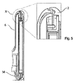
図4及び図5は、本発明による装置の断面を示している。本発明による装置は、本発明により物理蒸着法で塗布された金属層を含むとりわけ3D前面パネル2を備える。それにより、金属で作られた内部パネル(図1参照)は、省略することができる。したがって、表示装置は、概観が良くなり且つ軽量構造になる。前面パネル2は、特にスナップ機構により、ハウジング6に機械的に接続されている。この装置では、使用者には見えない赤外線センサーを使用するという選択肢もある。
4 and 5 show a cross section of the device according to the invention. The device according to the invention comprises in particular a
Claims (7)
前記前面パネルは、プラスチックで作られて、少なくとも部分的に、物理蒸着法により塗布された金属コーティングが設けられ、且つ
前記金属コーティングは接地されていることを特徴とする、表示装置(1)。 A display device (1) having a display (3) and a front panel (2),
The display device (1), wherein the front panel is made of plastic, provided with a metal coating at least partially applied by physical vapor deposition, and the metal coating is grounded.
Display device (1) according to any one of the preceding claims, characterized in that it comprises a rear housing (59).
Applications Claiming Priority (3)
| Application Number | Priority Date | Filing Date | Title |
|---|---|---|---|
| DE102010006658 | 2010-02-03 | ||
| DE102010006658.3 | 2010-02-03 | ||
| PCT/EP2011/000326 WO2011107189A2 (en) | 2010-02-03 | 2011-01-26 | Display device |
Related Child Applications (1)
| Application Number | Title | Priority Date | Filing Date |
|---|---|---|---|
| JP2016046662A Division JP6236487B2 (en) | 2010-02-03 | 2016-03-10 | Display device |
Publications (2)
| Publication Number | Publication Date |
|---|---|
| JP2013519109A true JP2013519109A (en) | 2013-05-23 |
| JP2013519109A5 JP2013519109A5 (en) | 2014-11-27 |
Family
ID=44542647
Family Applications (2)
| Application Number | Title | Priority Date | Filing Date |
|---|---|---|---|
| JP2012551535A Pending JP2013519109A (en) | 2010-02-03 | 2011-01-26 | Display device |
| JP2016046662A Active JP6236487B2 (en) | 2010-02-03 | 2016-03-10 | Display device |
Family Applications After (1)
| Application Number | Title | Priority Date | Filing Date |
|---|---|---|---|
| JP2016046662A Active JP6236487B2 (en) | 2010-02-03 | 2016-03-10 | Display device |
Country Status (6)
| Country | Link |
|---|---|
| US (1) | US9091572B2 (en) |
| EP (1) | EP2531820B1 (en) |
| JP (2) | JP2013519109A (en) |
| KR (1) | KR101793180B1 (en) |
| CN (1) | CN102859330B (en) |
| WO (1) | WO2011107189A2 (en) |
Families Citing this family (1)
| Publication number | Priority date | Publication date | Assignee | Title |
|---|---|---|---|---|
| CN108461044B (en) * | 2018-03-09 | 2021-03-12 | Oppo广东移动通信有限公司 | Electronic device and method for manufacturing the same |
Citations (12)
| Publication number | Priority date | Publication date | Assignee | Title |
|---|---|---|---|---|
| JPH10243481A (en) * | 1997-03-03 | 1998-09-11 | Matsushita Electric Ind Co Ltd | Remote control signal receiver and electronic device provided with it |
| JP2002027051A (en) * | 2000-07-11 | 2002-01-25 | Tokai Tsushin Kogyo Kk | Portable telephone with thermometer |
| JP2002287644A (en) * | 2001-03-26 | 2002-10-04 | Kenwood Corp | Display member and audio device |
| JP2005260429A (en) * | 2004-03-10 | 2005-09-22 | Nec Corp | Display module and mobile terminal |
| JP2005275076A (en) * | 2004-03-25 | 2005-10-06 | Seiko Epson Corp | Electro-optical device and electronic apparatus |
| JP2006253737A (en) * | 2005-03-07 | 2006-09-21 | Sony Corp | Electronic device with infrared receiving sensor |
| JP2008067236A (en) * | 2006-09-08 | 2008-03-21 | Kyocera Corp | Electronic equipment |
| JP2008103835A (en) * | 2006-10-17 | 2008-05-01 | Hirohisa Yano | Electromagnetic wave-reducing cellular telephone |
| JP2009090639A (en) * | 2007-09-18 | 2009-04-30 | Shin Etsu Polymer Co Ltd | Radio-wave-transmitting decorative member |
| US20090136723A1 (en) * | 2007-11-28 | 2009-05-28 | Lihong Zhao | Coated plastic sheet, a method for preparing same, and a housing using same |
| JP2009141778A (en) * | 2007-12-07 | 2009-06-25 | Casio Comput Co Ltd | Display unit structure, and digital camera |
| WO2009110090A1 (en) * | 2008-03-07 | 2009-09-11 | 三菱電機株式会社 | Decorative part |
Family Cites Families (16)
| Publication number | Priority date | Publication date | Assignee | Title |
|---|---|---|---|---|
| DE3622458A1 (en) * | 1986-07-04 | 1987-01-02 | H Peter Dipl Ing Nardin | Design of a dashboard in a motor vehicle |
| JPH0643313A (en) * | 1992-04-28 | 1994-02-18 | Nissha Printing Co Ltd | Production of front surface panel having infrared ray transmission filter |
| JP3276215B2 (en) * | 1993-07-30 | 2002-04-22 | 日本写真印刷株式会社 | Front panel and transfer material for front panel |
| US5572344A (en) * | 1995-01-03 | 1996-11-05 | Xerox Corporation | Pixel elements having resistive divider elements |
| DE19947504B4 (en) * | 1999-10-01 | 2004-06-03 | Robert Bosch Gmbh | Circuit arrangement for a motor vehicle cockpit |
| EP1240811B1 (en) * | 1999-12-01 | 2007-08-01 | Cool Options, Inc. | Structural frame of thermally conductive material |
| US6483719B1 (en) * | 2000-03-21 | 2002-11-19 | Spraylat Corporation | Conforming shielded form for electronic component assemblies |
| DE10047083A1 (en) * | 2000-09-22 | 2002-04-18 | Volkswagen Ag | Plastic panel for use e.g. in televisions and CD players and as components in cars, aero planes and ships has metallic coating with symbols applied to it |
| US6546621B2 (en) * | 2001-03-09 | 2003-04-15 | 3 View Technology Co., Ltd. | Package structure and method for a card |
| JP3568493B2 (en) * | 2001-06-18 | 2004-09-22 | 日本写真印刷株式会社 | Infrared transmission cover panel, decorative sheet for infrared transmission cover panel |
| US20040075982A1 (en) * | 2002-10-21 | 2004-04-22 | Kim David K. | Heat sink frame with improved electromagnetic interference (EMI) suppression characteristics |
| KR101054629B1 (en) * | 2003-02-28 | 2011-08-04 | 미츠비시 마테리알 가부시키가이샤 | Surge Absorbers and Manufacturing Method Thereof |
| JP4612505B2 (en) * | 2005-08-24 | 2011-01-12 | 富士通株式会社 | Electronics |
| US7977170B2 (en) * | 2006-10-03 | 2011-07-12 | Eastman Kodak Company | Flexible substrate with electronic devices and traces |
| US8731618B2 (en) * | 2009-04-23 | 2014-05-20 | Apple Inc. | Portable electronic device |
| US8287285B2 (en) | 2010-10-22 | 2012-10-16 | Johnson Controls Technology Company | System and method for reducing electromagnetic interference from a conductive interior trim component |
-
2011
- 2011-01-26 EP EP11703587.3A patent/EP2531820B1/en not_active Not-in-force
- 2011-01-26 WO PCT/EP2011/000326 patent/WO2011107189A2/en active Application Filing
- 2011-01-26 KR KR1020127023045A patent/KR101793180B1/en active IP Right Grant
- 2011-01-26 CN CN201180007949.9A patent/CN102859330B/en not_active Expired - Fee Related
- 2011-01-26 JP JP2012551535A patent/JP2013519109A/en active Pending
- 2011-01-26 US US13/575,015 patent/US9091572B2/en not_active Expired - Fee Related
-
2016
- 2016-03-10 JP JP2016046662A patent/JP6236487B2/en active Active
Patent Citations (12)
| Publication number | Priority date | Publication date | Assignee | Title |
|---|---|---|---|---|
| JPH10243481A (en) * | 1997-03-03 | 1998-09-11 | Matsushita Electric Ind Co Ltd | Remote control signal receiver and electronic device provided with it |
| JP2002027051A (en) * | 2000-07-11 | 2002-01-25 | Tokai Tsushin Kogyo Kk | Portable telephone with thermometer |
| JP2002287644A (en) * | 2001-03-26 | 2002-10-04 | Kenwood Corp | Display member and audio device |
| JP2005260429A (en) * | 2004-03-10 | 2005-09-22 | Nec Corp | Display module and mobile terminal |
| JP2005275076A (en) * | 2004-03-25 | 2005-10-06 | Seiko Epson Corp | Electro-optical device and electronic apparatus |
| JP2006253737A (en) * | 2005-03-07 | 2006-09-21 | Sony Corp | Electronic device with infrared receiving sensor |
| JP2008067236A (en) * | 2006-09-08 | 2008-03-21 | Kyocera Corp | Electronic equipment |
| JP2008103835A (en) * | 2006-10-17 | 2008-05-01 | Hirohisa Yano | Electromagnetic wave-reducing cellular telephone |
| JP2009090639A (en) * | 2007-09-18 | 2009-04-30 | Shin Etsu Polymer Co Ltd | Radio-wave-transmitting decorative member |
| US20090136723A1 (en) * | 2007-11-28 | 2009-05-28 | Lihong Zhao | Coated plastic sheet, a method for preparing same, and a housing using same |
| JP2009141778A (en) * | 2007-12-07 | 2009-06-25 | Casio Comput Co Ltd | Display unit structure, and digital camera |
| WO2009110090A1 (en) * | 2008-03-07 | 2009-09-11 | 三菱電機株式会社 | Decorative part |
Also Published As
| Publication number | Publication date |
|---|---|
| US9091572B2 (en) | 2015-07-28 |
| WO2011107189A3 (en) | 2011-12-29 |
| CN102859330B (en) | 2015-04-22 |
| JP6236487B2 (en) | 2017-11-22 |
| KR101793180B1 (en) | 2017-11-02 |
| US20130048856A1 (en) | 2013-02-28 |
| CN102859330A (en) | 2013-01-02 |
| JP2016173565A (en) | 2016-09-29 |
| EP2531820A2 (en) | 2012-12-12 |
| WO2011107189A2 (en) | 2011-09-09 |
| KR20120115569A (en) | 2012-10-18 |
| EP2531820B1 (en) | 2016-08-31 |
Similar Documents
| Publication | Publication Date | Title |
|---|---|---|
| JP6498720B2 (en) | Control display module for automobile | |
| KR102018741B1 (en) | Display device with cover window | |
| CN105739147B (en) | Display device | |
| JPWO2018083817A1 (en) | Image display device | |
| US20170115789A1 (en) | Touch-screen with front-mounted flexible display | |
| JP2014515848A (en) | Control display module for automobile | |
| US20220386491A1 (en) | Electronic device including waterproof structure | |
| KR20210152910A (en) | Electronic device including electrostatic induction structure | |
| JPWO2018168387A1 (en) | Touch panel and design structure having the same | |
| JP6236487B2 (en) | Display device | |
| US9939939B2 (en) | Interface module | |
| KR20220060773A (en) | Electronic device including waterproof structure | |
| US20220137667A1 (en) | Electronic device including waterproof structure | |
| CN113050315A (en) | Display device | |
| JP5824738B2 (en) | Operation panel structure | |
| KR102604357B1 (en) | Electronic device including display supporting structure | |
| US20230314856A1 (en) | Display device | |
| US20230047246A1 (en) | Flexible display module including shielding structure and waterproof structure and electronic device including the same | |
| US20230079135A1 (en) | Electronic device comprising electrostatic induction structure | |
| TWI639936B (en) | Touch module and touch display device with narrow border | |
| KR20220160218A (en) | Electronic device including waterproof structure | |
| US9366852B2 (en) | Corner reflector | |
| KR20230023287A (en) | Flexible display module including shielding structure and waterproof structure and electronic device including the same | |
| KR20230023166A (en) | Electronic device including waterproof structure | |
| KR20230086464A (en) | Display module including cushion layer and electronic device including display module |
Legal Events
| Date | Code | Title | Description |
|---|---|---|---|
| A621 | Written request for application examination |
Free format text: JAPANESE INTERMEDIATE CODE: A621 Effective date: 20131205 |
|
| A131 | Notification of reasons for refusal |
Free format text: JAPANESE INTERMEDIATE CODE: A131 Effective date: 20140715 |
|
| A977 | Report on retrieval |
Free format text: JAPANESE INTERMEDIATE CODE: A971007 Effective date: 20140716 |
|
| A524 | Written submission of copy of amendment under article 19 pct |
Free format text: JAPANESE INTERMEDIATE CODE: A524 Effective date: 20141007 |
|
| A131 | Notification of reasons for refusal |
Free format text: JAPANESE INTERMEDIATE CODE: A131 Effective date: 20150210 |
|
| A601 | Written request for extension of time |
Free format text: JAPANESE INTERMEDIATE CODE: A601 Effective date: 20150508 |
|
| A521 | Request for written amendment filed |
Free format text: JAPANESE INTERMEDIATE CODE: A523 Effective date: 20150609 |
|
| A02 | Decision of refusal |
Free format text: JAPANESE INTERMEDIATE CODE: A02 Effective date: 20151110 |