JP2013515607A - Precision weighing device - Google Patents
Precision weighing device Download PDFInfo
- Publication number
- JP2013515607A JP2013515607A JP2012547133A JP2012547133A JP2013515607A JP 2013515607 A JP2013515607 A JP 2013515607A JP 2012547133 A JP2012547133 A JP 2012547133A JP 2012547133 A JP2012547133 A JP 2012547133A JP 2013515607 A JP2013515607 A JP 2013515607A
- Authority
- JP
- Japan
- Prior art keywords
- chamber
- concentrate
- solvent
- piston
- volume
- Prior art date
- Legal status (The legal status is an assumption and is not a legal conclusion. Google has not performed a legal analysis and makes no representation as to the accuracy of the status listed.)
- Pending
Links
Images

Classifications
-
- G—PHYSICS
- G05—CONTROLLING; REGULATING
- G05D—SYSTEMS FOR CONTROLLING OR REGULATING NON-ELECTRIC VARIABLES
- G05D11/00—Control of flow ratio
- G05D11/006—Control of flow ratio involving a first fluid acting on the feeding of a second fluid
Landscapes
- Physics & Mathematics (AREA)
- General Physics & Mathematics (AREA)
- Engineering & Computer Science (AREA)
- Automation & Control Theory (AREA)
- Accessories For Mixers (AREA)
- Devices For Dispensing Beverages (AREA)
- Feeding, Discharge, Calcimining, Fusing, And Gas-Generation Devices (AREA)
Abstract
第1のチャンバ及び第2のチャンバと、第1のチャンバ内に配置されて第1のチャンバを混合部と駆動部とに区分するピストンと、第2のチャンバ内に配置され第2のチャンバ内の濃縮部を画定する第2のピストンとを備える装置を含む、精密計量装置が提供される。第2のチャンバの濃縮部は第1のチャンバの混合部と液体的に連通している。この提供される計量装置を利用した、濃縮物を溶媒に加える方法も提供される。 A first chamber and a second chamber; a piston disposed in the first chamber to divide the first chamber into a mixing portion and a driving portion; and a second chamber disposed in the second chamber. A precision metering device is provided, including a device comprising a second piston that defines a concentrating portion. The concentrating part of the second chamber is in liquid communication with the mixing part of the first chamber. A method of adding a concentrate to a solvent utilizing the provided metering device is also provided.
Description
本開示は広くは、溶液に精密量の濃縮物を加えるために用いられる計量装置に関する。 The present disclosure generally relates to a metering device used to add a precise amount of concentrate to a solution.
1つの流体の特定の量を他の流体又は溶液に量的比例関係で加えるために、産業全体にわたって計量装置が用いられている。例えば、飲料業界でソーダにシロップを加えるため、散水システムに肥料を加えるため、また解毒又は除染目的で水に添加剤を加えるためなどに、計量装置が用いられてきた。一般に計量システムは、混合ヘッドなどの混合装置を介して規定量の濃縮物を溶液の液体流中に投入する。濃縮物は通常、液体計量器によって液体流中の電磁弁に供給される信号の関数として、液体流中に計量投入される。このような計量システムは電子制御装置と機械弁とに依存するが、機械弁はやや精密性に劣ることがあり、また相当量のエネルギーを消費し得る。様々な液体用のピストンを受容するためのチャンバを備える単一の一体シリンダーを採用した、他の計量装置も知られており、これらの液体は装置下流において相互に加えられる。 Metering devices are used throughout the industry to add specific amounts of one fluid to other fluids or solutions in a quantitative proportional relationship. For example, metering devices have been used in the beverage industry to add syrup to soda, to add fertilizer to watering systems, and to add additives to water for detoxification or decontamination purposes. Generally, a metering system places a defined amount of concentrate into a liquid stream of solution via a mixing device such as a mixing head. The concentrate is typically metered into the liquid stream as a function of the signal supplied by the liquid meter to the solenoid valve in the liquid stream. Such metering systems rely on electronic controls and mechanical valves, which can be somewhat less precise and can consume a significant amount of energy. Other metering devices are also known that employ a single integral cylinder with a chamber for receiving pistons for various liquids, and these liquids are added to one another downstream of the device.
精密量の濃縮物を溶液に非常に高い希釈度で加えることができる装置が必要とされている。例えば、容積比で約1:1〜約1:10,000、約1:10〜約1:5,000又は更に約1:50〜約1:1000の範囲の希釈率で濃縮物を溶液に供給することが可能な装置が必要とされている。最新の装置でもこのような希釈率を達成することは困難である。追加的な電気エネルギーを要しない完全機械式の計量装置もまた、必要とされている。最後に、必要な溶液量とは独立に精密量の希釈溶液を常に供給する計量装置が必要とされている。 What is needed is an apparatus that can add a precise amount of concentrate to a solution at very high dilution. For example, the concentrate is brought into solution at a dilution ratio ranging from about 1: 1 to about 1: 10,000, from about 1:10 to about 1: 5,000, or even from about 1:50 to about 1: 1000 by volume. There is a need for a device that can be supplied. It is difficult to achieve such a dilution ratio even with the latest apparatus. There is also a need for a fully mechanical metering device that does not require additional electrical energy. Finally, there is a need for a metering device that constantly supplies a precise amount of diluted solution independent of the amount of solution required.
一態様では、第1の容積を有する第1のチャンバ及び第2の容積を有する第2のチャンバと、第1のチャンバ内に摺動可能に配置されて第1のチャンバを混合部と駆動部とに密閉可能に区分する第1のピストンと、第1のピストンに結合され、第2のチャンバ内に摺動可能に配置されて第2のチャンバ内の濃縮部を密閉可能に画定する第2のピストンとを含み、第1のチャンバ及び第2のチャンバの各々が少なくとも1つの外壁を有し、濃縮部が混合部と流体的に連通している装置が提供される。追加的な濃縮部を有する追加的なチャンバもまた、本開示の一部として想定される。 In one aspect, the first chamber having the first volume and the second chamber having the second volume, and the first chamber is slidably disposed in the first chamber so that the first chamber is mixed with the drive unit. A first piston that sealably seals; and a second piston coupled to the first piston and slidably disposed in the second chamber to sealably define a concentrating portion in the second chamber. And wherein each of the first chamber and the second chamber has at least one outer wall and the concentrating portion is in fluid communication with the mixing portion. Additional chambers with additional concentrators are also envisioned as part of this disclosure.
別の態様では、上述した装置を用意する工程と、第1のピストンを、第1のチャンバの混合部の容積が拡大しかつ第2のチャンバの濃縮部の容積が縮小する方向に付勢し、溶媒を1つ以上の溶媒源から第1のチャンバの混合部内へと流入させ、かつ濃縮物を第2のチャンバの濃縮部から濃縮物導管を通して混合チャンバ内へと流入させる工程と、混合部の容積が増大するにつれて濃縮物と溶媒とを混合して溶媒/濃縮物混合物を生成する工程と、濃縮物導管内の複数の弁であって第1のチャンバの内部又は近傍に配置された少なくとも1つの弁及び第2のチャンバの内部又は近傍に配置された少なくとも1つの弁を閉じ、かつ、第1のチャンバの混合部とも流体的に連通している出力導管と流体的に連通している、少なくとも1つの弁を開ける工程と、ピストンを反対方向に付勢して第2のチャンバ内の弁を開け、濃縮物を1つ以上の濃縮物源から濃縮物導管を通して第2のチャンバの濃縮部内へと流入させ、かつ溶媒/濃縮物混合物を出力導管を通して排出する工程と、を含む、濃縮物を溶媒に加える方法が提供される。上記の装置について説明したと同様に第3のチャンバ及び第3のピストンも本開示によって具現される。 In another aspect, the step of preparing the apparatus described above and the first piston are biased in a direction in which the volume of the mixing portion of the first chamber is increased and the volume of the concentration portion of the second chamber is reduced. Flowing the solvent from one or more solvent sources into the mixing section of the first chamber and flowing the concentrate from the concentrating section of the second chamber through the concentrate conduit into the mixing chamber; Mixing the concentrate with the solvent to increase the volume of the solvent to produce a solvent / concentrate mixture; and at least a plurality of valves in the concentrate conduit disposed in or near the first chamber Closes at least one valve located in or near one valve and the second chamber and is in fluid communication with an output conduit that is also in fluid communication with the mixing portion of the first chamber. Open at least one valve Urging the piston in the opposite direction to open the valve in the second chamber, allowing the concentrate to flow from one or more concentrate sources through the concentrate conduit and into the concentrator of the second chamber; and Draining the solvent / concentrate mixture through an output conduit, and providing a method of adding the concentrate to the solvent. Similar to the description of the above apparatus, a third chamber and a third piston are also embodied by the present disclosure.
本開示では、
「軸方向に整列」は2つ以上の部品が対称軸又は平行な対称軸を共有することを指す。
In this disclosure,
“Axial alignment” refers to the fact that two or more parts share a symmetry axis or a parallel symmetry axis.
「袋」は変形可能な容器を指す。 “Bag” refers to a deformable container.
「導管」は流体通路を指す。 “Conduit” refers to a fluid passage.
「流体」は液体又は気体を指す。 “Fluid” refers to liquid or gas.
「流体的に連通」は2つの装置又は装置の部品が相互に流体を直接伝達する状況を指すが、他の流量調整装置が流体連通システム内に含まれることもあると理解される。 “Fluidly communicating” refers to the situation where two devices or parts of a device directly transfer fluid to each other, but it is understood that other flow regulating devices may be included in the fluid communication system.
「リンク」は運動の伝達に用いられる要素のシステムを指し、このリンクは直接的な機械的リンクであってもよいし、後に機械的運動に変換されるエネルギー伝達媒体、例えば電磁弁に対する電気信号を介した、間接的なリンクであってもよい。 “Link” refers to a system of elements used to transmit motion, which may be a direct mechanical link or an electrical signal to an energy transfer medium, eg a solenoid valve, that is subsequently converted into mechanical motion. It may be an indirect link via
「機械的結合」はリンクを有する2つ以上の部品を指す。 “Mechanical connection” refers to two or more parts having links.
「比例的」は所定の一定比率によることを指すが、予測可能な方法で変化する比率によることを意味するとも解釈され得る。 “Proportional” refers to being based on a predetermined constant ratio, but can also be interpreted to mean by a ratio that changes in a predictable manner.
「溶媒」は濃縮物が加えられる任意の溶液を指し、純溶媒であるか溶液であるかを問わない。 “Solvent” refers to any solution to which a concentrate is added, whether pure solvent or solution.
提供される装置及び方法によれば、少量の濃縮物の精密計量が可能となり、必要な溶液量とは独立に精密量の希釈溶液を常に供給することが可能である。提供される装置及び方法は、例えば化学反応に触媒を加えたり、製品混合物に酸化防止剤、熱及び光安定剤、染料溶液、又はその他の液体添加剤を加えたりするのに有用であり得る。加えて、提供される装置及び方法は、飲用水に精密量の添加剤を投入するのにも有用であり得る。 With the apparatus and method provided, it is possible to precisely measure a small amount of concentrate and always supply a precise amount of dilute solution independent of the amount of solution required. The provided apparatus and method may be useful, for example, for adding a catalyst to a chemical reaction or adding an antioxidant, heat and light stabilizer, dye solution, or other liquid additive to a product mixture. In addition, the provided apparatus and method may be useful for injecting precise amounts of additives into drinking water.
上記の概要は、本発明の全ての実施の開示された各実施形態を記述することを意図したものではない。図面の簡単な説明及び後に続く発明を実施するための形態は、説明に役立つ実施形態をより詳しく例示する。 The above summary is not intended to describe each disclosed embodiment of every implementation of the present invention. BRIEF DESCRIPTION OF THE DRAWINGS The following detailed description and the detailed description set forth the illustrative embodiments in more detail.
以下の説明において、本明細書の説明の一部を構成し、いくつかの特定の実施形態が例として示される添付の一連の図面を参照する。本発明の範囲又は趣旨を逸脱せずに、その他の実施形態が考えられ、実施され得ることを理解すべきである。したがって、以下の詳細な説明は、限定する意味で理解すべきではない。 In the following description, reference is made to the accompanying series of drawings, which form a part hereof, and in which are shown by way of illustration several specific embodiments. It should be understood that other embodiments may be envisaged and practiced without departing from the scope or spirit of the invention. The following detailed description is, therefore, not to be taken in a limiting sense.
他に指示がない限り、本明細書及び添付の「特許請求の範囲」で使用される特徴寸法、量、物理特性を表わす数字は全て、どの場合においても用語「約」によって修飾されるものとして理解されるべきである。それ故に、そうでないことが示されない限り、前述の明細書及び添付の「特許請求の範囲」で示される数値パラメータは、当業者が本明細書で開示される教示内容を用いて、目標対象とする所望の特性に応じて、変化し得る近似値である。終点による数の範囲の使用は、その範囲内(例えば、1〜5は、1、1.5、2、2.75、3、3.80、4、及び5を含む)の全ての数及びその範囲内の任意の範囲を含む。 Unless otherwise indicated, all numbers representing characteristic dimensions, amounts, and physical properties used in this specification and the appended claims are, in each case, qualified by the term “about”. Should be understood. Therefore, unless indicated to the contrary, the numerical parameters set forth in the foregoing specification and the appended claims are intended to be used by those skilled in the art using the teachings disclosed herein. It is an approximate value that can vary depending on the desired characteristics to be performed. The use of a range of numbers by endpoint means that all numbers within that range (eg 1 to 5 include 1, 1.5, 2, 2.75, 3, 3.80, 4, and 5) and Includes any range within that range.
提供される精密計量装置は、本明細書において、図をもって更に説明される。図1に、提供される装置の一実施形態を示す。装置100は、第1のチャンバ110、第2のチャンバ120、第1のピストン112、第2のピストン122、リンク130、及び濃縮物導管140を含む。提供される装置では、第1のチャンバは典型的には、第2のチャンバの一定の容積より大きい、一定の容積を有する。第1のチャンバ110は2つの部分に区分される。すなわち、混合部114(第1のピストン112より上方の容積)及び駆動部116(第1のピストン112より下方の容積)である。混合部114の容積及び駆動部116の容積は第1のチャンバ110内の第1のピストン112の位置の関数として変化する。例えば、第1のピストン112が完全に進出した(図1に示すようにその上限位置にある)状態では、混合部114の容積は最小となり、したがって駆動部116の容積は最大となる。第2のピストン122は濃縮部126を画定する。
The provided precision metering device is further described herein with the aid of figures. FIG. 1 illustrates one embodiment of the apparatus provided. The
第1のチャンバは第2のチャンバと軸方向に整列してよい。例えば、第1のチャンバは共通軸を介して第2のチャンバと直接整列することができる。あるいは第2のチャンバは、第1の軸に平行な別の軸上にあって整列することもできる。あるいはまた、第2のチャンバは第1のチャンバが整列する軸に対して特定の角度のある軸を有することもできる。例えば、第2のチャンバを第1のチャンバに対して実質的に垂直にすることができるねじ歯車を用いることが可能である。適切な歯車によって、他の任意の角度とすることもまた、可能である。 The first chamber may be axially aligned with the second chamber. For example, the first chamber can be directly aligned with the second chamber via a common axis. Alternatively, the second chamber can be on and aligned with another axis parallel to the first axis. Alternatively, the second chamber can have an axis that is at a particular angle with respect to the axis with which the first chamber is aligned. For example, it is possible to use a screw gear that can make the second chamber substantially perpendicular to the first chamber. Any other angle is also possible with appropriate gears.
第1のチャンバ又は第2のチャンバが回転対称にある必要はない。例えば、第1のピストンと第2のピストンとの間のリンクは一方又は他方のピストンの中心からずれていてもよい。 The first chamber or the second chamber need not be rotationally symmetric. For example, the link between the first piston and the second piston may be offset from the center of one or the other piston.
リンク130は、第1のピストン112と第2のピストン122との間における機械的運動の伝達を可能にするものであれば、任意のシステムであってよい。図1では、リンクは一般リンク要素である130によって表されている。リンク130は、例えば第1のピストン112及び第2のピストン122に機械的に連結される固体棒であってもよいし、又は実施形態によっては、棒要素の各先端に第1のピストン112及び第2のピストン122を備える棒要素である。したがって、一実施形態では、第1のピストン112、リンク130(棒要素)、及び第2のピストン122は全て1つの部品をなす。別の実施形態では、リンク130は例えば連結棒、半径方向リンク、軸方向リンク、シフトリンク、クラッチリンク、回転リンク、ぜん動リンク、ばね若しくはばねシステム、歯車若しくは歯車システム、油圧システム、伸縮システム、磁気結合システム、又は機械的運動を比例的に第1のピストン112から第2のピストン122へと伝達することができるその他のシステムであってよい。加えて、リンクは、電気信号などの信号がピストン間の結合リンクの一部であり得るという意味において間接的であってもよい。例えば、1つのピストンが電気信号を、この信号を電磁弁を介して機械的運動に変換することが可能な別のピストンに送ってもよい。
The
第1のチャンバ110及び第2のチャンバ120は、流体を収容することが可能な任意の容積要素の形状であってよい。例えば、第1のチャンバ110、第2のチャンバ120又はその両方は、円筒形であってもよい。しかしながら、第1のチャンバ110及び第2のチャンバ120について、別の容積要素形状もまた想定される。例えば、第1のチャンバ110、第2のチャンバ120、又はその両方が、三角形からより多くの辺を有する多角形まで、任意の種類の多角形である断面を有する斜方体形状であってもよい。第1のピストン112は、この第1のピストン112の縁が第1のチャンバ110の外壁全体に接触して第1のチャンバ110を上述したような2つの部分に区分する封を形成するように、第1のチャンバ110内に配置される。同様に、第2のピストン122は、この第2のピストン122の縁が第2のチャンバ120の外壁全体に接触して濃縮部を画定する封を形成するように、第2のチャンバ120内に配置される。両チャンバ内において、封は、流体がチャンバの一方の部分から同チャンバの他方の部分へと実質的に移動するのを防ぐように意図されている。第1のチャンバは第1のチャンバに通じる複数の開口部を備えてよく、第2のチャンバは第2のチャンバに通じる複数の開口部を備えてよい。これらの開口部は典型的には導管に接続される。
The
具現された装置では、第2のチャンバ120の濃縮部126は第1のチャンバ110の混合部114と流体的に連通している。図1では、流体連通は濃縮物導管140を介する。濃縮物導管140はチューブ、パイプ、チャネル、ホース、通路、ダクト、トンネル、トラフ、又は第2のチャンバ120の濃縮部126から第1のチャンバ110の混合部114内へと流体を流すことができる部品の任意の組み合せであってよい。濃縮物導管140は他のアイテム、例えば濾過器、計量器、絞り、圧力変換器、逆流防止弁、又は第2のチャンバ120から第1のチャンバ110への流体の流れの速さ、圧力、及び方向を変更することができる他の任意のアイテムを含んでもよい。随意選択的な逆流防止弁が図1に示されているが、これらは単に例示を目的とするものである。逆流防止弁144は、第2のピストン122の進出により濃縮物が第1のチャンバ110の濃縮部126から押し出された後にこの濃縮物が逆流するのを防ぐ。逆流防止弁142は、第1のピストン112の進出中における濃縮物の逆流を防止する。第1のピストンと機械的結合状態にある追加的なピストンを備えた追加的な濃縮物チャンバがあってもよく、そのような追加的な濃縮物チャンバもまた第1の円筒の混合部と流体的に連通していてよいことが、想定される。
In the implemented apparatus, the concentrating
典型的には、有用な濃縮物としては例えば、酸化防止剤、熱及び光安定剤、化学線吸収剤、染料、並びに分散色素などの製剤補助剤、触媒、薬剤、アジュバント、共溶剤、香味料、ビタミン、ミネラル、殺菌剤、消臭剤、防汚剤、並びに清かん剤などが挙げられる。 Typically useful concentrates include, for example, formulation aids such as antioxidants, heat and light stabilizers, actinic radiation absorbers, dyes, and disperse pigments, catalysts, drugs, adjuvants, co-solvents, flavoring agents. Vitamins, minerals, bactericides, deodorants, antifouling agents, and cleansing agents.
溶媒に濃縮物を加える方法は、やはり図1を参照することにより最もよく説明され得る。図1は垂直方向に示されるが、これは限定するためではなく、提供される方法を説明するためにのみ、本明細書において用いられるものである。溶媒導管152を介して第1のチャンバ110の混合部114と流体的に連通している溶媒源150が設けられている。同様に、濃縮物導管162を介して第2のチャンバ120の濃縮部126と流体的に連通している濃縮物源160が設けられている。濃縮物源160は濃縮物を有する容器であってよい。容器は例えばタンク、ビン、箱、又は袋であってよい。図1に示した実施形態では、溶媒の逆流を防ぐために溶媒導管152内に逆流防止弁154が設けられ、濃縮物の逆流を防ぐために濃縮物導管162内に逆流防止弁164が設けられている。
The method of adding the concentrate to the solvent can also be best described by referring again to FIG. Although FIG. 1 is shown in a vertical direction, this is not intended to be limiting, but is used herein only to illustrate the method provided. A
第1のピストン112が、第1のチャンバ110の混合部114の容積を増大するように(図1では下向きに)付勢される。第1のピストン112のこの運動により、溶媒が溶媒源150から導管152及び逆流防止弁154を通して混合部114内へと引き込まれる。同時に、第2のピストン122が第1のピストン112の運動に対して比例的に動いて第2のチャンバ120の濃縮部126の容積を縮小し、濃縮物を逆流防止弁144を通して濃縮物導管140内へ、更に逆流防止弁142を通して第1のチャンバ110の混合部114内へ、と送り込む。このようにして、計量された量の濃縮物及び溶媒が同時に混合部114を満たし、混合部114は同混合部の容積にかかわらず、同じ濃度の濃縮物及び溶媒を有する。混合は静的に行われてもよいし、又は、混合部114と連通する追加的な混合要素があってもよく、この要素を利用することによって混合が行われてもよい。このように第1のピストン112を付勢する間、図1に例示した実施形態では、逆流防止弁142、144及び154は開位置にあって、矢印で示される方向の流れを可能にするとともに、逆流防止弁156及び164は閉位置にあって矢印で示される方向の流れに抗する。
The
混合部114がその最大容積(これは第1のピストン112の行程長により決定される任意の容積であり得る)に達した後、逆流防止弁142、144、及び154が閉められ、逆流防止弁156及び164が開けられる。逆流防止弁は、単に流れの方向に反応することによって受動的にその状態を変化させるものであってもよいし、外部の制御システムによって油圧又は電子的に操作されるものとしてもよい。第1のピストン112はその後、混合部114の容積を縮小するように(図1では上向きに)付勢される。この運動により、溶媒と濃縮物との混合物が逆流防止弁156を通して、また溶媒/濃縮物混合物導管158を通して、最終用途又は保存容器(図示せず)へと送り出される。同時に第2のピストン122が、第2のチャンバ120の濃縮部126の容積を増大するように比例的に動く。この運動により、濃縮物が濃縮物源160から濃縮物導管162及び逆流防止弁164を通して流れ、濃縮部126内の濃縮物を補充する。
After the mixing
随意選択的な逆流防止弁176を備える流体入力導管172及び逆流防止弁178を備える流体出力導管174が、図1の一部として例示されている。入力導管172は流体を第1のチャンバ110の駆動部116内へと導く手段となる。有用な流体には液体又は気体が挙げられる。流体は第1のピストン112に油圧的揚力を与えることができる。この流体は任意の液体又は気体であってよく、ポンプによって駆動部116内へと送り込まれてもよい。第1のピストン112が反対方向に付勢されると、流体は駆動部116から出力導管174を通して流出し、例えば容器へと戻ることができる。
A
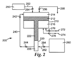
図2は提供される精密計量装置の一実施形態の例である。この実施形態では装置200は、第1のチャンバ210、第2のチャンバ220、第1のピストン212、第2のピストン222、及び濃縮物導管240を含む。第1のチャンバ210は2つの部分に区分される。すなわち、混合部214(第1のピストン212より上方の容積)及び駆動部216(第1のピストン212より下方の容積)である。混合部214の容積及び駆動部216の容積は、図1に示した実施形態について上述したと同じように、第1のチャンバ210の第1のピストン212の位置の関数として変化する。図2に示した実施形態では、第1のピストン212及び第2のピストン222は、相互間のリンクとして固体棒を有する。この実施形態では、第1のピストン212及び第2のピストン222は実際には一体である。第1のピストン212及び第2のピストン222は軸方向に整列していることから、第1のピストン212が混合部214の容積を増大するように付勢されるとき、第2のピストン222は共通軸に沿って等しい距離だけ動いて濃縮部226内の容積を縮小する。
FIG. 2 is an example of one embodiment of a precision metering device provided. In this embodiment, the
図2はまた、(逆流防止弁254を備える)溶媒導管252を通して第1のチャンバ210の混合部214と流体的に連通している溶媒源250、(逆流防止弁264を備える)導管262を通して第2のチャンバ220の濃縮部226と流体的に連通している濃縮物源260、(逆流防止弁256を備える)溶媒/濃縮物混合物導管258、濃縮物導管240を通る濃縮物の流れを制御するための逆流防止弁242及び244、並びに随意選択的なものとして、逆流防止弁276を備える流体入力導管272及び逆流防止弁278を備える流体出力導管274を示している。
FIG. 2 also illustrates a
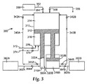
図3は、提供される装置の別の実施形態を例示する。図3は、第1のチャンバ310、第2のチャンバ320A、及び第3のチャンバ320Bを含む、装置300を示している。溶媒源350は溶媒導管352及び逆流防止弁354を通して第1のチャンバ310の混合部314と流体的に連通している。第1の濃縮物源360Aは濃縮物導管362A及び逆流防止弁364Aを介して第2のチャンバ320Aの濃縮部316Aと流体的に連通しており、第2の濃縮物源360Bは濃縮物導管362B及び逆流防止弁364Bを介して第3のチャンバ320Bの濃縮部316Bと流体的に連通している。更に、濃縮部316Aは、逆流防止弁342A及び344Aを備える流体導管340Aを通して第1のチャンバ310の混合部314と流体的に連通しており、濃縮部316Bは、逆流防止弁342B及び344Bを備える流体導管340Bを通して第1のチャンバ310の混合部314と流体的に連通している。第1のピストン312が第1のチャンバ310を混合部314と駆動部318とに区分する。駆動部318は逆流防止弁376を含む流体入力導管372及び逆流防止弁378を含む流体出力導管374と流体的に連通している。第1のピストン312は第2のピストン322A及び第3のピストン322Bの両方と機械的結合状態にある。第2のチャンバ320Aは第3のチャンバ320Bと寸法、容積、及び形状が異なってよい。同様に、第2のピストン322Aは第3のピストン322Bと寸法及び形状が異なってよい。第1のチャンバ310の混合部314もまた、(逆流防止弁356を備える)溶媒/混合物導管358と流体的に連通している。図3には示されないが、第2のピストン及び第3のピストンは、第1のピストン312に対してそれぞれ独立に異なる種類のリンクを有することができると想定される。
FIG. 3 illustrates another embodiment of the provided apparatus. FIG. 3 shows an
図示した実施形態は、第1のチャンバと、濃縮物を含む1つ又は2つの第2のチャンバとを備える。また、追加的な濃縮物を収容する、第1のチャンバの混合部と流体的に連通している追加的なチャンバを設けてもよいことも、想定される。 The illustrated embodiment comprises a first chamber and one or two second chambers containing concentrate. It is also envisioned that an additional chamber may be provided that is in fluid communication with the mixing portion of the first chamber that contains additional concentrate.
提供される装置及び方法は、濃縮物を精密計量して溶媒中に加えるのに有用である。提供される装置を用い、第1のチャンバの混合部内において濃縮物の比例的な量を溶媒中に加えることにより、混合部内の溶媒/濃縮物混合物が、混合部の容積(第1のピストンの位置)にかかわらず同じ比率を有することが可能となる。適切な歯車を用いることによって、この比率は1:1(溶媒/濃縮物容積比)から極めて高い希釈率までの範囲にわたり得る。例えば濃縮物は、容積比で1:1、1:20、1:50、1:100、1:500、1:1000、1:10,000又はより高い比率で希釈することが可能である。操作モードによっては、第1のピストン、第2のピストン、又はその両方が、第1のチャンバ又は第2のチャンバの一定容積全体を変化させなくてもよいこともまた、想定される。濃縮物導管を通して第1のチャンバの混合チャンバ内へと押し出される濃縮物の量が機械的又は電気的なストップによって制限され得ることもまた、想定される。 The provided apparatus and method are useful for accurately metering concentrates into a solvent. Using the apparatus provided, by adding a proportional amount of concentrate into the solvent in the mixing section of the first chamber, the solvent / concentrate mixture in the mixing section is mixed with the volume of the mixing section (of the first piston). It is possible to have the same ratio regardless of the position). By using appropriate gears, this ratio can range from 1: 1 (solvent / concentrate volume ratio) to very high dilution rates. For example, the concentrate can be diluted at a volume ratio of 1: 1, 1:20, 1:50, 1: 100, 1: 500, 1: 1000, 1: 10,000, or higher. It is also envisioned that depending on the mode of operation, the first piston, the second piston, or both may not change the entire constant volume of the first chamber or the second chamber. It is also envisioned that the amount of concentrate pushed through the concentrate conduit and into the mixing chamber of the first chamber can be limited by a mechanical or electrical stop.
リンクは様々であり、かつ/又は機械的若しくは電気的制御システムを用いて調整可能であり得ることもまた、想定される。例えばリンクは制御システムにより、装置の操作中に調整可能及び変更可能であり得る。 It is also envisioned that the links can vary and / or be adjustable using a mechanical or electrical control system. For example, the link may be adjustable and changeable during operation of the device by the control system.
提供される装置及び方法は、例えば反応混合物に触媒を加えたり、液体製品流若しくは液体製品に添加剤を加えたり、薬剤を製剤したり、又は食品若しくは飲料に添加剤を加えたりするのに有用であり得る。提供される装置及び方法は、希釈率が極めて重要で製品の容積が小さい場合に非常に有用である。提供される装置及び方法により、バッチ製剤に代り、要求に応じて大量又は少量の溶媒/濃縮物混合物を供給することの可能な、信頼性の高い精密計量システムが実現できる。 The apparatus and methods provided are useful, for example, for adding a catalyst to a reaction mixture, adding an additive to a liquid product stream or liquid product, formulating a drug, or adding an additive to a food or beverage. It can be. The provided apparatus and method is very useful when dilution rate is extremely important and the volume of the product is small. The provided apparatus and method provides a reliable precision metering system that can supply large or small amounts of solvent / concentrate mixtures on demand instead of batch formulations.
実施形態によっては、提供される装置は独自の電源を用いる必要がない。例えばシステムは、第1のチャンバの駆動部内へと流入して第1のピストンを一方向に付勢する廃水流と、対抗力として作用してピストンを反対方向に付勢し得る溶媒源とによって駆動されることも可能である。 In some embodiments, the provided device need not use a unique power source. For example, the system may include a wastewater stream that flows into the drive of the first chamber to bias the first piston in one direction and a solvent source that can act as a counter force to bias the piston in the opposite direction. It can also be driven.
本発明の範囲及び趣旨から逸脱しない本発明の様々な変更や改変は、当業者には明らかとなるであろう。本発明は、本明細書で述べる例示的な実施形態及び実施例によって不当に限定されるものではないこと、また、こうした実施例及び実施形態は、本明細書において以下に記述する「特許請求の範囲」によってのみ限定されると意図する本発明の範囲に関する例示のためにのみ提示されることを理解すべきである。本開示に引用された全ての参照文献は、その全体が参照により本明細書に組み込まれる。 Various changes and modifications of this invention will become apparent to those skilled in the art without departing from the scope and spirit of this invention. The present invention is not unduly limited by the exemplary embodiments and examples described herein, and such examples and embodiments are described below in the claims. It is to be understood that these are provided for illustration only with respect to the scope of the present invention which is intended to be limited only by the “range”. All references cited in this disclosure are hereby incorporated by reference in their entirety.
Claims (19)
前記第1のチャンバ内に摺動可能に配置されて前記第1のチャンバを混合部と駆動部とに密閉可能に区分する第1のピストンと、
前記第1のピストンに結合され、前記第2のチャンバ内に摺動可能に配置されて前記第2のチャンバ内の濃縮部を密閉可能に画定する第2のピストンと、を含み、
前記第1のチャンバ及び前記第2のチャンバの各々が少なくとも1つの外壁を有し、前記濃縮部が前記混合部と流体的に連通している、装置。 A first chamber having a first volume and a second chamber having a second volume;
A first piston that is slidably disposed within the first chamber and that sealably divides the first chamber into a mixing portion and a drive portion;
A second piston coupled to the first piston and slidably disposed within the second chamber to sealably define a concentrating portion within the second chamber;
The apparatus wherein each of the first chamber and the second chamber has at least one outer wall and the concentrating portion is in fluid communication with the mixing portion.
前記第1のピストンを、前記第1のチャンバの前記混合部の容積が拡大しかつ前記第2のチャンバの前記濃縮部の容積が縮小する方向に付勢し、溶媒を1つ以上の溶媒源から前記第1のチャンバの前記混合部内へと流入させ、かつ濃縮物を前記第2のチャンバの前記濃縮部から濃縮物導管を通して前記混合チャンバ内へと流入させる工程と、
前記混合部の前記容積が増大するにつれて前記濃縮物と前記溶媒とを混合して溶媒/濃縮物混合物を生成する工程と、
前記濃縮物導管内の複数の弁であって前記第1のチャンバの内部又は近傍に配置された少なくとも1つの弁及び前記第2のチャンバの内部又は近傍に配置された少なくとも1つの弁を閉じ、かつ、前記第1のチャンバの前記混合部とも流体的に連通している出力導管と流体的に連通している、少なくとも1つの弁を開ける工程と、
前記ピストンを反対方向に付勢して前記第2のチャンバ内の弁を開け、濃縮物を1つ以上の濃縮物源から前記濃縮物導管を通して前記第2のチャンバの前記濃縮部内へと流入させ、かつ前記溶媒/濃縮物混合物を出力導管を通して排出する工程と、を含む、濃縮物を溶媒に加える方法。 Preparing the apparatus according to any one of claims 1 to 10, a concentrate source having a concentrate, and a solvent source having a solvent;
The first piston is urged in a direction in which the volume of the mixing portion of the first chamber is increased and the volume of the concentration portion of the second chamber is reduced, and the solvent is supplied to one or more solvent sources. Flowing into the mixing section of the first chamber from and from the concentration section of the second chamber through a concentrate conduit into the mixing chamber;
Mixing the concentrate and the solvent to produce a solvent / concentrate mixture as the volume of the mixing section increases;
Closing at least one valve located in or near the first chamber and at least one valve located in or near the second chamber in the concentrate conduit; And opening at least one valve in fluid communication with an output conduit in fluid communication with the mixing portion of the first chamber;
The piston is biased in the opposite direction to open the valve in the second chamber, allowing the concentrate to flow from one or more concentrate sources through the concentrate conduit and into the concentrator of the second chamber. Discharging the solvent / concentrate mixture through an output conduit, and adding the concentrate to the solvent.
Applications Claiming Priority (3)
| Application Number | Priority Date | Filing Date | Title |
|---|---|---|---|
| US29069909P | 2009-12-29 | 2009-12-29 | |
| US61/290,699 | 2009-12-29 | ||
| PCT/US2010/061426 WO2011090652A2 (en) | 2009-12-29 | 2010-12-21 | Precision metering device |
Publications (2)
| Publication Number | Publication Date |
|---|---|
| JP2013515607A true JP2013515607A (en) | 2013-05-09 |
| JP2013515607A5 JP2013515607A5 (en) | 2013-11-28 |
Family
ID=44223789
Family Applications (1)
| Application Number | Title | Priority Date | Filing Date |
|---|---|---|---|
| JP2012547133A Pending JP2013515607A (en) | 2009-12-29 | 2010-12-21 | Precision weighing device |
Country Status (6)
| Country | Link |
|---|---|
| US (1) | US20130039146A1 (en) |
| EP (1) | EP2519864B1 (en) |
| JP (1) | JP2013515607A (en) |
| CN (1) | CN102741769A (en) |
| BR (1) | BR112012016008A2 (en) |
| WO (1) | WO2011090652A2 (en) |
Families Citing this family (2)
| Publication number | Priority date | Publication date | Assignee | Title |
|---|---|---|---|---|
| US20100260892A1 (en) * | 2009-04-08 | 2010-10-14 | Nestec S.A. | Mixing nozzle fitments |
| CN111992070B (en) * | 2020-09-07 | 2022-05-03 | 周夫 | Pressure pump type pipeline dosing device |
Citations (6)
| Publication number | Priority date | Publication date | Assignee | Title |
|---|---|---|---|---|
| JPS52140466A (en) * | 1976-05-17 | 1977-11-24 | Pinkaaton Harii | Liquid treating system |
| JPS54107274U (en) * | 1978-01-14 | 1979-07-28 | ||
| JPH09299781A (en) * | 1996-05-17 | 1997-11-25 | Seibutsukei Tokutei Sangyo Gijutsu Kenkyu Suishin Kiko | Liquid agent infecting/mixing device |
| JP2006088120A (en) * | 2004-09-27 | 2006-04-06 | Chiyuuden Plant Kk | Drain discharge apparatus |
| JP2008023423A (en) * | 2006-07-19 | 2008-02-07 | Hiroshima Univ | Mixed liquid feeding device and its control method |
| JP2010534133A (en) * | 2007-07-25 | 2010-11-04 | ダブリュー・アール・グレイス・アンド・カンパニー−コネチカット | Method and apparatus for weighing and dispensing fluids in two actions |
Family Cites Families (14)
| Publication number | Priority date | Publication date | Assignee | Title |
|---|---|---|---|---|
| US492945A (en) * | 1893-03-07 | Churn | ||
| US357027A (en) * | 1887-02-01 | Eobbet g- | ||
| SE325720B (en) * | 1967-12-27 | 1970-07-06 | Alfa Laval Ab | |
| FR2240439A1 (en) * | 1973-08-06 | 1975-03-07 | Remion Guy | Dosing system for liquids or pastes - has movable volumetric pumps to permit simple and precise dose adjustment |
| US4440500A (en) * | 1982-06-21 | 1984-04-03 | Polyurethane Technology Of America-Martin Sweets Company, Inc. | High pressure impingement mixing apparatus |
| DE3225076A1 (en) * | 1982-07-05 | 1984-01-05 | Bacillolfabrik Dr. Bode + Co GmbH & Co KG, 2000 Hamburg | DEVICE FOR ADDING DISINFECTANT TO WATER |
| DK350584A (en) * | 1984-07-18 | 1986-01-19 | Arne Bent Sjoegren | MIXING PUMP FOR EFFECTIVE MIXING (HOMOGENIZATION) OF TWO OR MORE LIQUIDS (AIR SPECIES) WITH A CONSTANT, BUT REGULAR, MIXING CONDITIONS |
| CN1005962B (en) * | 1985-07-17 | 1989-12-06 | 阿如那·本徒·守古人 | Mixing pump used for delivering and effective mixing (homogenizing) of two or more liquids (gases) with constant (but adjustable) proportion of liquids |
| GB8812047D0 (en) * | 1988-05-21 | 1988-06-22 | Garnett R H | Improvements in/relating to chemical concentrate metering |
| US5873492A (en) * | 1997-01-28 | 1999-02-23 | Coltene/Whaledent, Inc. | Dispensing bag for dynamic mixer |
| US6062722A (en) * | 1997-10-21 | 2000-05-16 | Micron Communications, Inc. | Fluid mixing and withdrawing methods |
| JP4150533B2 (en) * | 2002-05-10 | 2008-09-17 | 岡▲崎▼ 美惠子 | Disinfection water production equipment |
| CN1749900A (en) * | 2004-09-17 | 2006-03-22 | 边威 | Method for controlling two way fluid flow fixed ratio and flow sum |
| US8257594B2 (en) * | 2008-02-07 | 2012-09-04 | 3M Innovative Properties Company | Twin tank water-on-water filtration system |
-
2010
- 2010-12-21 BR BR112012016008A patent/BR112012016008A2/en not_active IP Right Cessation
- 2010-12-21 US US13/519,519 patent/US20130039146A1/en not_active Abandoned
- 2010-12-21 EP EP10801525.6A patent/EP2519864B1/en not_active Not-in-force
- 2010-12-21 JP JP2012547133A patent/JP2013515607A/en active Pending
- 2010-12-21 WO PCT/US2010/061426 patent/WO2011090652A2/en active Application Filing
- 2010-12-21 CN CN2010800592381A patent/CN102741769A/en active Pending
Patent Citations (6)
| Publication number | Priority date | Publication date | Assignee | Title |
|---|---|---|---|---|
| JPS52140466A (en) * | 1976-05-17 | 1977-11-24 | Pinkaaton Harii | Liquid treating system |
| JPS54107274U (en) * | 1978-01-14 | 1979-07-28 | ||
| JPH09299781A (en) * | 1996-05-17 | 1997-11-25 | Seibutsukei Tokutei Sangyo Gijutsu Kenkyu Suishin Kiko | Liquid agent infecting/mixing device |
| JP2006088120A (en) * | 2004-09-27 | 2006-04-06 | Chiyuuden Plant Kk | Drain discharge apparatus |
| JP2008023423A (en) * | 2006-07-19 | 2008-02-07 | Hiroshima Univ | Mixed liquid feeding device and its control method |
| JP2010534133A (en) * | 2007-07-25 | 2010-11-04 | ダブリュー・アール・グレイス・アンド・カンパニー−コネチカット | Method and apparatus for weighing and dispensing fluids in two actions |
Also Published As
| Publication number | Publication date |
|---|---|
| US20130039146A1 (en) | 2013-02-14 |
| WO2011090652A3 (en) | 2012-08-16 |
| EP2519864B1 (en) | 2014-02-26 |
| EP2519864A2 (en) | 2012-11-07 |
| BR112012016008A2 (en) | 2016-08-16 |
| WO2011090652A2 (en) | 2011-07-28 |
| CN102741769A (en) | 2012-10-17 |
Similar Documents
| Publication | Publication Date | Title |
|---|---|---|
| EP3204733B1 (en) | Low pressure fluctuation flow control apparatus and method | |
| US7544050B1 (en) | Hydraulic proportioning system | |
| CN102215946A (en) | Liquid mixing device | |
| JP2013515607A (en) | Precision weighing device | |
| JP5739450B2 (en) | Water-on-water filtration system with high-precision weighing device | |
| WO2013117918A1 (en) | Dispensing apparatus | |
| RU2614705C2 (en) | Antiscalant dosing device | |
| CN207195810U (en) | Spacing valve valve handle can be realized | |
| CN201880242U (en) | Fluid driven multi-media proportional mixing device | |
| CN210066360U (en) | Papermaking bactericide adding system | |
| RU2496295C1 (en) | Automatic device for application of liquid fertiliser to irrigation water | |
| CN203862221U (en) | Water power metering, mixing and dosing device | |
| US11465110B2 (en) | Scaleable inline buffer dilution scheme | |
| US6840406B2 (en) | Proportional volumetric injector-dispenser | |
| CN105327658B (en) | A kind of mixer and its control algolithm | |
| CN203737222U (en) | Reaction kettle | |
| CN216922393U (en) | Fluid adding plunger pump for dairy product production | |
| SU787901A1 (en) | Liquid-volume mixer | |
| WO2021070172A1 (en) | Autonomous liquid dosing system | |
| AU2019204030A1 (en) | A mixer and mixing system for mixing an agrochemical with a liquid, and related systems and methods | |
| Zlobich | Pumping on-farm: water solutions | |
| Gogolin | Dosing pumps in practical applications | |
| SU1457981A1 (en) | Installation for mixing liquids | |
| PUMPS | Chemical Injection Methods for Irrigation | |
| CN104235122A (en) | Apparatus for conditioning a hydraulic fluid |
Legal Events
| Date | Code | Title | Description |
|---|---|---|---|
| A521 | Request for written amendment filed |
Free format text: JAPANESE INTERMEDIATE CODE: A523 Effective date: 20131009 |
|
| A621 | Written request for application examination |
Free format text: JAPANESE INTERMEDIATE CODE: A621 Effective date: 20131009 |
|
| A977 | Report on retrieval |
Free format text: JAPANESE INTERMEDIATE CODE: A971007 Effective date: 20141015 |
|
| A02 | Decision of refusal |
Free format text: JAPANESE INTERMEDIATE CODE: A02 Effective date: 20150331 |