JP2013515280A - How to stabilize contact lenses - Google Patents
How to stabilize contact lenses Download PDFInfo
- Publication number
- JP2013515280A JP2013515280A JP2012544885A JP2012544885A JP2013515280A JP 2013515280 A JP2013515280 A JP 2013515280A JP 2012544885 A JP2012544885 A JP 2012544885A JP 2012544885 A JP2012544885 A JP 2012544885A JP 2013515280 A JP2013515280 A JP 2013515280A
- Authority
- JP
- Japan
- Prior art keywords
- lens
- design
- eye
- zone
- contact lens
- Prior art date
- Legal status (The legal status is an assumption and is not a legal conclusion. Google has not performed a legal analysis and makes no representation as to the accuracy of the status listed.)
- Pending
Links
Images


Classifications
-
- G—PHYSICS
- G02—OPTICS
- G02C—SPECTACLES; SUNGLASSES OR GOGGLES INSOFAR AS THEY HAVE THE SAME FEATURES AS SPECTACLES; CONTACT LENSES
- G02C7/00—Optical parts
- G02C7/02—Lenses; Lens systems ; Methods of designing lenses
- G02C7/024—Methods of designing ophthalmic lenses
- G02C7/028—Special mathematical design techniques
-
- G—PHYSICS
- G02—OPTICS
- G02C—SPECTACLES; SUNGLASSES OR GOGGLES INSOFAR AS THEY HAVE THE SAME FEATURES AS SPECTACLES; CONTACT LENSES
- G02C7/00—Optical parts
- G02C7/02—Lenses; Lens systems ; Methods of designing lenses
- G02C7/024—Methods of designing ophthalmic lenses
-
- G—PHYSICS
- G02—OPTICS
- G02C—SPECTACLES; SUNGLASSES OR GOGGLES INSOFAR AS THEY HAVE THE SAME FEATURES AS SPECTACLES; CONTACT LENSES
- G02C7/00—Optical parts
- G02C7/02—Lenses; Lens systems ; Methods of designing lenses
- G02C7/04—Contact lenses for the eyes
-
- G—PHYSICS
- G02—OPTICS
- G02C—SPECTACLES; SUNGLASSES OR GOGGLES INSOFAR AS THEY HAVE THE SAME FEATURES AS SPECTACLES; CONTACT LENSES
- G02C7/00—Optical parts
- G02C7/02—Lenses; Lens systems ; Methods of designing lenses
- G02C7/04—Contact lenses for the eyes
- G02C7/047—Contact lens fitting; Contact lenses for orthokeratology; Contact lenses for specially shaped corneae
-
- G—PHYSICS
- G02—OPTICS
- G02C—SPECTACLES; SUNGLASSES OR GOGGLES INSOFAR AS THEY HAVE THE SAME FEATURES AS SPECTACLES; CONTACT LENSES
- G02C7/00—Optical parts
- G02C7/02—Lenses; Lens systems ; Methods of designing lenses
- G02C7/04—Contact lenses for the eyes
- G02C7/048—Means for stabilising the orientation of lenses in the eye
-
- G—PHYSICS
- G02—OPTICS
- G02C—SPECTACLES; SUNGLASSES OR GOGGLES INSOFAR AS THEY HAVE THE SAME FEATURES AS SPECTACLES; CONTACT LENSES
- G02C2202/00—Generic optical aspects applicable to one or more of the subgroups of G02C7/00
- G02C2202/06—Special ophthalmologic or optometric aspects
Abstract
コンタクトレンズを安定させる方法は、安定ゾーンパラメータの公称セットを有するレンズ設計を提供することと、運動量率のバランスをとることに基づいてレンズ設計にメリット関数を適用することと、安定ゾーンパラメータの公称セットを有するレンズ設計にメリット関数を適用することに基づいて、安定化が改善されたコンタクトレンズ設計を作製することと、を含む。 Methods for stabilizing contact lenses include providing a lens design with a nominal set of stable zone parameters, applying a merit function to the lens design based on balancing momentum rates, and a nominal stability zone parameter. Creating a contact lens design with improved stabilization based on applying a merit function to the lens design having the set.
Description
特定の視覚欠損の矯正は、円筒型、二焦点、又は多焦点の特性など、非球状矯正特性をコンタクトレンズの1つ以上の面に応用することによって達成され得る。これらのレンズが有効であるためには、眼の上にある間にレンズが特定の配向でほぼ保たれなければならない。レンズの眼上での配向の維持は、典型的には、レンズの機械的特性を変えることによって行われる。レンズの背面に対する前面の偏心化、下方レンズ周縁部の厚さの増大、レンズ表面上における凹部又は隆起部の形成、及びレンズ縁部の切断などのプリズムの安定化は、安定化手法の例である。これに加えて、薄いゾーン、即ちレンズ周縁部の厚さが減少する領域を使用することによってレンズを安定化させる動的安定化が用いられてきた。典型的には、薄いゾーンは、レンズの眼上の配置の有利な地点から、レンズの垂直軸又は水平軸のいずれかに関して対称である2つの領域に位置する。 Correction of certain visual defects can be achieved by applying non-spherical correction characteristics, such as cylindrical, bifocal, or multifocal characteristics, to one or more surfaces of the contact lens. In order for these lenses to be effective, the lens must remain approximately in a particular orientation while on the eye. Maintaining the orientation of the lens on the eye is typically done by changing the mechanical properties of the lens. Stabilization of the prism, such as decentration of the front surface relative to the back of the lens, increase in the thickness of the lower lens periphery, formation of recesses or ridges on the lens surface, and cutting of the lens edge are examples of stabilization techniques. is there. In addition to this, dynamic stabilization has been used to stabilize the lens by using a thin zone, i.e. a region where the thickness of the lens periphery decreases. Typically, the thin zone is located in two regions that are symmetrical with respect to either the vertical or horizontal axis of the lens, from an advantageous point of placement of the lens on the eye.
レンズ設計の評価は、眼上のレンズの性能に関して判断した後、もしも必要かつ可能であれば、設計を最適化することを伴う。このプロセスは、通常、試験設計を患者で臨床的に評価することによって行われる。しかしながら、このプロセスは、患者間のばらつきを考慮する必要があるので、かなりの人数の試験を受ける患者を必要とするという理由から、時間及び費用がかかる。 Evaluation of the lens design entails optimizing the design, if necessary and possible, after making a determination regarding the performance of the lens on the eye. This process is usually done by clinical evaluation of the study design in the patient. However, this process is time consuming and expensive because it requires consideration of patient-to-patient variability and requires a significant number of patients to be tested.
特定のコンタクトレンズの安定化を改善するための継続的必要性が存在する。 There is a continuing need to improve the stabilization of certain contact lenses.
本発明は、公称安定化設計と比較して、安定化が改善されて設計されたコンタクトレンズである。 The present invention is a contact lens designed with improved stabilization compared to a nominal stabilization design.
本発明の別の態様において、コンタクトレンズを安定させる方法は、安定ゾーンパラメータの公称セットを有するレンズ設計と、レンズ設計の眼上での性能を評価することと、この性能に基づいてメリット関数を計算することと、メリット関数を適用することによって安定ゾーンパラメータを最適化することと、を組み込む。このプロセスは、まばたきなどの眼の機械的構造の影響をシミュレートし、それに合わせて安定化スキームを調整する(例えば、ソフトウェアベースの)仮想モデルを介して繰り返し行われてもよい。 In another aspect of the invention, a method of stabilizing a contact lens includes a lens design having a nominal set of stability zone parameters, evaluating the eye performance of the lens design, and a merit function based on the performance. Incorporating calculating and optimizing stable zone parameters by applying a merit function. This process may be iterated through a virtual model (eg, software-based) that simulates the effects of eye mechanical structure such as blinking and adjusts the stabilization scheme accordingly.
本発明の更に別の態様において、コンタクトレンズは、眼上のレンズに作用するトルクの角運動量のバランスをとるスキームに従って安定化される。 In yet another aspect of the invention, the contact lens is stabilized according to a scheme that balances the angular momentum of torque acting on the lens on the eye.
本発明の更に別の態様において、コンタクトレンズは、レンズの残部とは異なる厚さを有する1つ以上のゾーンの形成によって安定化され、その場合、これらのゾーンは、レンズが眼上にあるときにレンズに作用するトルクの角運動量のバランスがとれるように、レンズ上に位置決めされる。 In yet another aspect of the invention, the contact lens is stabilized by the formation of one or more zones having a different thickness than the remainder of the lens, where these zones are when the lens is on the eye. It is positioned on the lens so that the angular momentum of the torque acting on the lens is balanced.
本発明の更に別の態様において、コンタクトレンズは、その長さのほとんどがレンズの水平軸の下にある安定ゾーンを有する。 In yet another aspect of the invention, the contact lens has a stability zone whose length is mostly below the horizontal axis of the lens.
本発明の更に別の態様において、コンタクトレンズは、一つの方向に対して他の方向に、(ピークからの)異なる勾配変化率を有する安定ゾーンを有する。 In yet another aspect of the invention, the contact lens has a stable zone with a different rate of slope change (from the peak) in one direction relative to the other.
本発明の更に別の態様において、コンタクトレンズは、水平軸の下方に有するのとは異なる高さプロファイルを水平軸の上方に有する。 In yet another aspect of the invention, the contact lens has a different height profile above the horizontal axis than it has below the horizontal axis.
本発明のコンタクトレンズは、レンズに作用する様々な力のバランスをとることに基づいて安定化を最適化する設計を有する。これは、眼、眼の構成要素、及び最終的には眼の上に置かれた安定化レンズに作用するトルクのバランスをとる設計プロセスの適用を含む。好ましくは、安定化要素を含む公称設計から改良プロセスを開始することによって、安定化が改善される。例えば、中心を通る水平軸及び垂直軸の両方に関して対称である2つの安定ゾーンを有するレンズ設計は、本発明の方法に従ってレンズの安定化を最適化する際の好都合な基準である。「安定ゾーン」とは、辺縁ゾーンの残りの領域の平均厚さよりも大きな厚さの値を有する、レンズの辺縁ゾーンを意味する。「辺縁ゾーン」とは、レンズの光学ゾーンを周囲方向に取り囲み、かつレンズの縁部まで延びるがこれを含まないレンズ表面の領域を意味する。有用な出発点である別の安定化設計は、参照により本明細書に組み込まれる米国特許公報第20050237482号に記載されているが、いかなる安定化設計を公称設計として用いることもでき、該設計はその後、本発明に従って最適化される。安定化設計改良プロセスは、後述の眼モデルで改良点を試験し、この試験の結果を評価し、望ましいレベルの安定化が達成されるまで改良プロセスを繰り返し続けることを組み込むこともできる。 The contact lens of the present invention has a design that optimizes stabilization based on balancing the various forces acting on the lens. This includes the application of a design process that balances the torque acting on the eye, the eye components, and ultimately the stabilizing lens placed on the eye. Preferably, stabilization is improved by starting the refinement process from a nominal design that includes a stabilizing element. For example, a lens design having two stability zones that are symmetric about both the horizontal and vertical axes through the center is a convenient criterion in optimizing lens stabilization according to the method of the present invention. By “stable zone” is meant a lens edge zone having a thickness value greater than the average thickness of the remaining regions of the edge zone. “Edge zone” means the area of the lens surface that surrounds the optical zone of the lens in the circumferential direction and extends to the edge of the lens but does not include it. Another stabilization design that is a useful starting point is described in US Patent Publication No. 20050237482, which is incorporated herein by reference, but any stabilization design can be used as a nominal design, It is then optimized according to the present invention. The stabilization design improvement process can also incorporate testing the improvements in the eye model described below, evaluating the results of this test, and continuing the improvement process repeatedly until the desired level of stabilization is achieved.
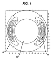
図1は、安定化レンズの前側、つまり対象側表面を示している。レンズ10は光学ゾーン11を有する。レンズ周縁部は光学ゾーン11を取り囲んでいる。2つの厚い領域12が周縁部に位置しており、これらが安定ゾーンである。
FIG. 1 shows the front side of the stabilizing lens, ie the object side surface. The
新しい設計を作製するためのプロセスで好ましく使用されるモデルには、機械的操作及びレンズ安定性に与える影響をシミュレートする様々な要素及び仮定が組み込まれている。好ましくは、このモデルは、周知のプログラミング技術に従って、標準的プログラミング技術及びコーディング技術を用いて、ソフトウェアに落とし込まれる。概括的には、このモデルは、所定の回数のまばたきの際の後述の力の印加をシミュレートすることによって、安定化レンズを設計するためのプロセスで使用される。レンズが回転しかつ偏心する程度を、それに応じて判定する。その後、回転及び/又はセントレーション(centration)をより望ましいレベルにするのを目的とする方法で、設計に変更が加えられる。次にこれを再度モデルにかけて、予め定められた回数のまばたきの後に、まばたきの際の移動を判定する。設計の変更は、より詳細に後述されるメリット関数の適用によって達成される。 A model that is preferably used in the process for creating a new design incorporates various elements and assumptions that simulate the effects on mechanical operation and lens stability. Preferably, this model is dropped into software using standard programming and coding techniques according to well-known programming techniques. In general, this model is used in a process for designing a stabilizing lens by simulating the application of forces described below during a predetermined number of blinks. The degree to which the lens rotates and decenters is determined accordingly. Thereafter, changes are made to the design in a way that aims to bring rotation and / or centration to a more desirable level. Next, this is applied again to the model, and after a predetermined number of blinks, the movement at the time of blinking is determined. The design change is achieved by applying a merit function, described in more detail below.
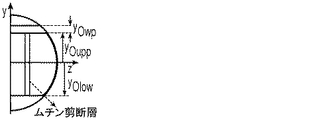
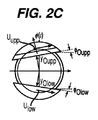
モデルは、眼が、角膜及び強膜を表す好ましくは少なくとも2つの球面部分からなり、x−y−z座標軸の原点が、角膜を表す球面の中心にあると仮定している。非球面といったより複雑な面を使用することも可能である。レンズの底面形状は球面部分からなるが、レンズの基本曲線半径は、レンズの中心から縁部に向かって変化し得る。背面を記述するために、1つを超える基本曲線を使用することができる。眼上に配置されたレンズは、眼と同一形状をとると仮定する。レンズの厚さ分布は、必ずしも回転対称である必要はなく、実際には、本発明のレンズの一部の好ましい実施形態によると、対称ではない。レンズ縁部の厚いゾーンを用いて、レンズの位置及び配向挙動を制御することができる。レンズと眼との間には、均一な液体の薄膜(涙液層)が存在し、その典型的な厚さは5μmである。この涙液層は、レンズ下涙液層と呼ばれる。レンズ縁部では、レンズと眼との間の液膜の厚さはずっと薄く、ムチン涙液層と呼ばれる。典型的な厚さが5.0μmである均一な液体の薄膜(これも涙液層)が、レンズと下眼瞼及び上眼瞼との間に存在し、これらは、レンズ上涙液層と呼ばれる。下眼瞼及び上眼瞼の両方の境界は、x−y平面に単位法線ベクトルを有する平面内にある。したがって、z軸に対して垂直な平面上のこれら境界の突出部は、直線である。この仮定は、眼瞼が動いている間も成立する。上眼瞼は、コンタクトレンズに均一な圧力を加える。この均一な圧力は、コンタクトレンズの上眼瞼で覆われた全領域、又はこの領域の上眼瞼の境界に近い一部に、均一な幅(眼瞼の縁部を表す曲線を通る平面に対して垂直な方向に測定した場合)で加えられる。下眼瞼は、コンタクトレンズに均一な圧力を加える。この圧力は、コンタクトレンズの下眼瞼で覆われた全領域に加えられる。眼瞼によってコンタクトレンズに加えられる圧力は、コンタクトレンズの不均一な厚さ分布(厚いゾーン)(特に縁部近く)を介してレンズに作用するトルクの原因となる。この圧力がコンタクトレンズに作用するトルクに与える影響は、メロンシード効果(melon seed effect)と呼ばれる。レンズが眼に対して動くと、レンズ下涙液層に粘性摩擦が存在する。粘性摩擦は、レンズが眼に対して動くときに、レンズ縁部と眼との間のムチン涙液層にも存在する。更に、レンズが動く及び/又は眼瞼が動くと、レンズ上涙液層に粘性摩擦が存在する。レンズの歪み及び応力は、レンズの変形によって生じる。こうした歪み及び応力は、レンズの弾性エネルギー容量となる。レンズが眼に対して動き、かつレンズの変形が変化するにつれて、弾性エネルギー容量は変化する。レンズは、弾性エネルギー容量が最小である位置に向かう傾向がある。 The model assumes that the eye consists of preferably at least two spherical parts representing the cornea and sclera, and the origin of the xyz coordinate axis is at the center of the spherical surface representing the cornea. It is also possible to use more complex surfaces such as aspheric surfaces. The bottom surface shape of the lens consists of a spherical portion, but the basic curve radius of the lens can change from the center of the lens toward the edge. More than one basic curve can be used to describe the back side. Assume that the lens placed on the eye takes the same shape as the eye. The thickness distribution of the lens need not necessarily be rotationally symmetric, in fact it is not symmetric according to some preferred embodiments of the lens of the present invention. Thick zones at the lens edge can be used to control the position and orientation behavior of the lens. There is a uniform thin liquid film (tear layer) between the lens and the eye, with a typical thickness of 5 μm. This tear film is called the sublens tear film. At the lens edge, the thickness of the liquid film between the lens and the eye is much thinner and is called the mucin tear film. A uniform liquid film (also a tear film) with a typical thickness of 5.0 μm is present between the lens and the lower and upper eyelids, which are called the upper lens tear film. The boundaries of both the lower and upper eyelids lie in a plane that has a unit normal vector in the xy plane. Therefore, these boundary protrusions on a plane perpendicular to the z-axis are straight lines. This assumption holds even while the eyelid is moving. The upper eyelid applies uniform pressure to the contact lens. This uniform pressure is applied to the entire area covered by the upper eyelid of the contact lens, or to a part close to the boundary of the upper eyelid in this area, with a uniform width (perpendicular to the plane passing through the curve representing the edge of the eyelid) When measured in any direction). The lower eyelid applies uniform pressure to the contact lens. This pressure is applied to the entire area covered by the lower eyelid of the contact lens. The pressure exerted on the contact lens by the eyelids causes a torque acting on the lens through a non-uniform thickness distribution (thick zone) of the contact lens (especially near the edge). The effect of this pressure on the torque acting on the contact lens is called the melon seed effect. As the lens moves relative to the eye, viscous friction exists in the sublens tear film. Viscous friction is also present in the mucin tear film between the lens edge and the eye as the lens moves relative to the eye. Furthermore, when the lens moves and / or the eyelids move, there is viscous friction in the tear film above the lens. Lens distortion and stress are caused by lens deformation. Such strain and stress become the elastic energy capacity of the lens. As the lens moves relative to the eye and the lens deformation changes, the elastic energy capacity changes. The lens tends towards the position where the elastic energy capacity is minimal.
眼(角膜及び強膜)の形状、レンズの底面形状、及び眼瞼の動きを表すパラメータが、図2に示されている。レンズの動きは、レンズに作用する角運動量のバランスから得られる。慣性効果は無視される。すると、レンズに作用する全てのモーメントの合計は0となる。したがって次の通りである。

最初の4つのモーメントは抵抗トルクであり、レンズの動きに線形従属である。残りのトルクは駆動トルクである。この角運動量のバランスにより、レンズの位置βに関する非線形一次微分方程式が得られる。
この等式は、四次Runge−Kutta積分スキームで解かれる。コンタクトレンズ上の点の位置は、回転ベクトルβ(t)に関する回転から得られる。点の古い位置を現在の位置に変換する回転行列R(t)は、次のロドリゲスの公式から得られる。
数値積分法では、時間離散化が用いられる。すると、レンズの動きは多数のその後の回転であると考えることができるので、次の時間ステップでは、
![]()
![]()
![]()
![]()
![]()
![]()
![]()
![]()
回転行列は、レンズの回転
![]()
![]()
![]()
![]()
![]()
![]()
レンズの回転は、レンズの中心線に関した回転である。偏心は、(x、y)平面内の線に関した回転である。したがって、レンズの位置は、中心線と、その後に続く偏心
![]()
![]()
![]()
![]()
本発明の好ましい方法において、これらの関係に基づくメリット関数(MF)は、公称設計を調整し、それによって公称設計の安定化スキームを改善するように作り上げられる。こうしたメリット関数は、眼上でのレンズ性能要件に基づいて定義される。好ましい実施形態において、メリット関数は、これらに限定されないが、a)レンズの回転及びセントレーション性能(等式1)、b)静止位置周辺でのレンズの安定性(等式2)、又はc)静止位置周辺のレンズの回転及びセントレーション性能並びに安定性(等式3)であると定義される。
レンズの回転とは、まばたき中及びまばたきの間に生じる、z軸を中心とするレンズの角運動を意味する。回転は、眼上のレンズの初期位置、又は眼上でモデル化された場合のレンズの挙動に応じて、時計回りであっても反時計回りであってもよい。 The rotation of the lens means an angular movement of the lens around the z axis that occurs during and during blinking. The rotation may be clockwise or counterclockwise depending on the initial position of the lens on the eye or the behavior of the lens when modeled on the eye.
レンズのセントレーションとは、レンズの幾何学的中心と角膜頂点との間の距離を意味する。セントレーションは、角膜頂点の平面内のx−y座標系に記録される。 Lens centration means the distance between the geometric center of the lens and the apex of the cornea. Centration is recorded in the xy coordinate system in the plane of the corneal apex.
レンズ安定性とは、水平方向(x軸)及び垂直方向(y軸)のレンズの最大移動の量、並びにまばたき期間の間のレンズの回転量を意味する。レンズ安定性は、レンズがその最終位置に到達した後に、レンズの誤配向及び偏心なしに記録されるのが好ましい。 Lens stability means the maximum amount of lens movement in the horizontal direction (x-axis) and vertical direction (y-axis), and the amount of lens rotation during the blink period. Lens stability is preferably recorded without lens misorientation and decentration after the lens reaches its final position.
等式1をメリット関数の目的及び適用の例として用いると、Rot及びCentは、それぞれ、最適化されるレンズ設計の回転及びセントレーションにおけるレンズ性能を表す。RREF及びCREFは、初期レンズ設計の回転及びセントレーションにおけるレンズ性能を表す変数である。WR及びWCは、一方の係数の寄与を他方の係数に対して調整するのを可能にする2つの重み係数であり、0〜1の値を取り得る。適用される場合、以下に例示されるように、これらの関数は、数値的に解かれるのが最良である。重み係数は、目的の構成要素に適切な考慮がなされるように適用される。それらは同等であってもよく、又は一方の構成要素が他方より関与していてもよい。そのため、例えば、セントレーションよりも回転を最適化することがより問題である場合、WCよりも大きなWRを選択することになる。この構成下で、安定化設計のメリット関数が、先行する設計に比べて減少させられた場合に、安定化設計は改善される。更に、そのような場合にメリット関数が最小化されると、安定化設計は最適化される。当然のことながら、安定化以外の理由で、あるレンズ設計が他のものよりも好ましい場合があるので、設計の安定化の面を必ずしも最適化せずに、本発明に従って安定化の改善が行われてもよい。
等式2において、XRange、YRange及びθRangeは、最適化されるレンズ設計の水平方向、垂直方向、及び回転の安定性におけるレンズ性能を表し、XREF、YREF、及びθREFは、初期レンズ設計の水平方向、垂直方向、及び回転の安定性におけるレンズ性能を表し、WX、WY、及びWθは、互いに対する係数の寄与の調整を可能にする重み係数を表す。
等式3において、Rot、Cent、及びStabは、最適化されるレンズ設計の回転、セントレーション、及び安定性におけるレンズ性能を表し、RREF、CREF、及びSREFは、初期レンズ設計の回転、セントレーション、及び安定性におけるレンズ性能を表し、RREF、CREF、及びSREFは、互いに対する係数の寄与の調整を可能にする重み係数を表す。
In
別の実施形態では、メリット関数は装着快適性を含み、更には、安定ゾーンの体積、安定ゾーンの表面積、安定ゾーンに対するソフトコンタクトレンズ装着者の認識、又は任意のその他の関連基準を含むこともできる。 In another embodiment, the merit function includes wearing comfort and may further include stability zone volume, stability zone surface area, soft contact lens wearer awareness of the stability zone, or any other relevant criteria. it can.
更なる好ましい実施形態では、メリット関数は、次のパラメータから上述されたものと同じ様式で定義される。
−回転性能:
−回転曲線反応の下の表面積
−+/−5.0度以内の回転で静止位置に到達するまでの時間
−初期回転速度
−セントレーション性能:
−セントレーション曲線反応の下の表面積
−セントレーションで静止位置に到達するまでの時間
−最初に最終静止位置に到達したとき
−セントレーション速度
−安定性性能:
−水平方向への移動の大きさ
−垂直方向への移動の大きさ
−回転の大きさ
−水平移動の持続時間
−上下移動の持続時間
−回転の持続時間。
−装着快適性:
−安定ゾーン構成のための余剰材料の体積
−安定ゾーンに覆われた表面積
−安定ゾーンに対するレンズ装着者の認識
In a further preferred embodiment, the merit function is defined in the same manner as described above from the following parameters:
-Rotation performance:
-Surface area under rotation curve reaction-Time to reach rest position with rotation within +/- 5.0 degrees-Initial rotation speed-Centration performance:
-Surface area under the centration curve reaction-Time to reach rest position with centration-When first final rest position is reached-Centration speed-Stability performance:
-Horizontal movement magnitude-Vertical movement magnitude-Rotation magnitude-Horizontal movement duration-Vertical movement duration-Rotation duration.
-Wearing comfort:
-Volume of surplus material for stable zone construction-Surface area covered by stable zone-Lens wearer's perception of stable zone
本方法によってもたらされ得る安定化のタイプに制限はない。安定ゾーンは、次のタイプのものであり得る。
−X軸及びY軸に対して対称
−X軸又はY軸に対して対称
−X軸及びY軸の両方に対して非対称
−一定の半径方向距離
−可変の半径方向距離
There is no limit to the type of stabilization that can be provided by the method. The stability zone can be of the following type:
-Symmetric with respect to X and Y axes-Symmetric with respect to X or Y axis-Asymmetric with respect to both X and Y axes-Constant radial distance-Variable radial distance
次を含むがこれらに限定されない様々な安定ゾーンパラメータが、最適化の間に評価され得る;ゾーン長さ、ピーク厚さの位置、ピークの両側の傾斜角度、ゾーン周辺の傾斜、及びゾーン幅。最適化パラメータとしては、レンズ直径、基本曲線、厚さ、光学ゾーンの直径、辺縁ゾーンの幅、材料特性、レンズの特徴を記述するその他のパラメータも挙げることができる。 Various stable zone parameters can be evaluated during optimization, including but not limited to: zone length, peak thickness location, slope angle on both sides of the peak, slope around the zone, and zone width. Optimization parameters can also include lens diameter, basic curve, thickness, optical zone diameter, marginal zone width, material properties, and other parameters that describe lens characteristics.
本発明の好ましい実施形態では、2つのタイプの改善アプローチが開示される。まず、完全最適化が行われ、その場合、MFによって誘導される安定化調整が所定の回数繰り返される眼上挙動モデルは、レンズが静止位置に達するまでに数回のまばたきサイクルを必要とする。別の実施形態では、設計は、所定の回数のまばたきサイクルの間に改善される。3回のまばたきサイクルは、一般に、有意義な安定化の改善をもたらすのに有効な最低数である。いずれの場合も、このプロセスは、公称設計にMFを適用しながら繰り返し行われる。3回のまばたきサイクルが用いられる場合には、最初のまばたきはレンズを水平から角度αに向け、中間のまばたきではレンズは水平から角度βに向けられ、最後のまばたきではレンズは静止位置に位置付けられる。最も好ましい実施形態では、角度αは45度に設定され、角度βは22度に設定される(しかし、これら角度は共にこれらの値に限定されない)。別の実施形態では、最適化プロセスは両方のアプローチの組み合わせであり、その場合、少ない回数のまばたきサイクルを予備的に用いて中間解に到達した後、数回のまばたきサイクルを用いて、最適化が許容可能な程度まで行われたかが検証される。 In a preferred embodiment of the present invention, two types of improvement approaches are disclosed. First, full optimization is performed, in which case the on-eye behavior model in which the stabilization adjustment induced by MF is repeated a predetermined number of times requires several blink cycles before the lens reaches the rest position. In another embodiment, the design is improved during a predetermined number of blink cycles. Three blink cycles are generally the lowest number effective to provide a meaningful stabilization improvement. In either case, this process is repeated while applying MF to the nominal design. If three blink cycles are used, the first blink will point the lens from horizontal to angle α, the middle blink will direct the lens from horizontal to angle β, and the last blink will position the lens in the rest position. . In the most preferred embodiment, the angle α is set to 45 degrees and the angle β is set to 22 degrees (but these angles are not both limited to these values). In another embodiment, the optimization process is a combination of both approaches, in which case a few blink cycles are preliminarily used to arrive at an intermediate solution and then several blink cycles are used to optimize Is verified to an acceptable level.
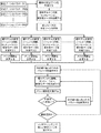
図3は、この改良プロセスのフローチャートを示す。安定ゾーンの最初の設計は、既存の設計であっても新しい設計であってもよい。これらの設計からの安定ゾーンパラメータが決定される。これらのパラメータが初期値周辺で変更される場合には、これらのパラメータは設計性能を計算することで得られる。レンズ性能に最も大きな変化を与えるパラメータが、最適化プロセスのために選択されるのが好ましい。工程1において、考慮される安定ゾーンパラメータが選択される。これらには、多くの他のものの中でも、例えば、安定ゾーンの大きさ(Z0)、経度0〜180度に沿ったピーク位置(r0)、経度約0〜180度に関して角度をなすピーク位置(θ0)、ピーク位置の上下の勾配、安定ゾーンの角測長(σθ)、ピーク位置を中心に回転された安定ゾーン、及び安定ゾーンの幅(σR)が挙げられる。
FIG. 3 shows a flowchart of this refinement process. The initial design of the stability zone may be an existing design or a new design. Stable zone parameters from these designs are determined. When these parameters are changed around the initial values, these parameters can be obtained by calculating the design performance. The parameter that gives the greatest change in lens performance is preferably selected for the optimization process. In
工程2において、レンズは安定ゾーンパラメータに関して数学的に定義されて、初期又は公称設計を得る。安定ゾーンを記述する数学関数の種類に制限はない。安定ゾーンは、CADアプリケーションなどのコンピュータ生成ソフトウェアを用いて記述されることも可能である。(定義されたパラメータを用いて)数学的に記述された設計は、工程3において眼モデルに入れられて、表1に示されるような回転、セントレーション、及び安定性データが生成される。次に、このデータを使用して、任意工程4において、安定化パラメータの1つ以上を変更することができる。
安定ゾーンは、再成形、拡大縮小、回転、転位のいずれかによって、又は現在の設計を変更するための任意の他の技術を用いて変更される。工程5a〜5dにおいて、変更された安定化パラメータは再度眼モデルに入れられて、今は変更された設計のそれぞれに関する回転、セントレーション、及び安定性データを生成する。対応する工程6a〜6dの各ケースにおいて、メリット関数が作成されかつ新しい各設計に適用されて、工程7及び8において、レンズが操作される(好ましくは回転により)際に、新たな回転、セントレーション、及び安定性データを生成する。この場合も同様に、各繰り返しにおいて、工程9でメリット関数が計算され、工程10において、それらが減少しているかどうかを確かめるためにチェックされる。減少は、前回の繰り返しを超える改善である。メリット関数が減少しなかった場合には、任意工程11において安定化パラメータを再度変更することができ、その結果得られた変更されたレンズ設計は、選択及びデータ生成工程7及び8に戻される。メリット関数が減少した場合、それは安定化の改善を示し、レンズ設計は最終設計であると決定されるか(工程12)、又は任意工程13において、他のゾーンが再度改善される。
The stability zone is changed either by reshaping, scaling, rotation, dislocation, or using any other technique for changing the current design. In steps 5a-5d, the modified stabilization parameters are re-entered into the eye model to generate rotation, centration, and stability data for each of the modified designs. In each case of the corresponding steps 6a-6d, a merit function is created and applied to each new design, and when the lens is manipulated (preferably by rotation) in steps 7 and 8, a new rotation, cent. Generation and stability data. Again, at each iteration, the merit function is calculated at
本発明は、乱視用レンズ及び多焦点レンズにおいて最大の有用性を見出すことができる。更に、この設計は、特定の個人の角膜トポグラフィーに合わせてカスタマイズされたレンズ、高い波面収差補正を有するレンズ、又はその両方において有益であり得る。好ましくは、本発明は、例えば、参照によりその全体が本明細書に組み込まれる米国特許第5,652,638号、同第5,805,260号、及び同第6,183,082号に開示されているような乱視用レンズ又は乱視用多焦点レンズを安定させるために用いられる。 The present invention can find maximum utility in astigmatic lenses and multifocal lenses. Further, this design may be beneficial in lenses that are customized for a particular individual's corneal topography, lenses that have high wavefront aberration correction, or both. Preferably, the present invention is disclosed, for example, in US Pat. Nos. 5,652,638, 5,805,260, and 6,183,082, which are incorporated herein by reference in their entirety. It is used to stabilize an astigmatic lens or multi-focal lens for astigmatism.
更に別の代替方法として、本発明のレンズは、高い眼収差、角膜トポグラフィーデータ、又はその両方の補正を取り入れてもよい。かかるレンズの例は、参照によりその全体が本明細書に組み込まれる米国特許第6,305,802号及び同第6,554,425号に見られる。 As yet another alternative, the lenses of the present invention may incorporate correction for high ocular aberrations, corneal topography data, or both. Examples of such lenses can be found in US Pat. Nos. 6,305,802 and 6,554,425, which are incorporated herein by reference in their entirety.
本発明のレンズは、これらに限定されないが、メガネのレンズ、コンタクトレンズ、及び眼内レンズを含む眼科用レンズを製造するのに好適な任意のレンズ成形材料から製造され得る。ソフトコンタクトレンズを形成するための例示的な材料としては、これらに限定されないがシリコーンエラストマー、シリコーン含有マクロマー、例えば、これらに限定されないが、米国特許第5,371,147号、同第5,314,960号、及び同第5,057,578号(これらは、参照によりその全体が本明細書に組み込まれる)に開示されているもの、ヒドロゲル、シリコーン含有ヒドロゲルなど、及びこれらの組み合わせが挙げられる。より好ましくは、表面はシロキサンであるか、又はポリジメチルシロキサンマクロマー、メタクリルオキシプロピルポリアルキルシロキサン及びそれらの混合物、シリコーンヒドロゲル若しくはヒドロゲル、例えばエタフィルコンAを含むがこれらに限定されないシロキサン官能基を含む。 The lenses of the present invention can be made from any lens molding material suitable for making ophthalmic lenses, including but not limited to eyeglass lenses, contact lenses, and intraocular lenses. Exemplary materials for forming the soft contact lens include, but are not limited to, silicone elastomers, silicone-containing macromers, such as, but not limited to, US Pat. Nos. 5,371,147, 5,314. 960, and 5,057,578, which are hereby incorporated by reference in their entirety, hydrogels, silicone-containing hydrogels, and the like, and combinations thereof. . More preferably, the surface is a siloxane or includes siloxane functional groups including but not limited to polydimethylsiloxane macromers, methacryloxypropyl polyalkylsiloxanes and mixtures thereof, silicone hydrogels or hydrogels such as etafilcon A.
レンズ材料の硬化は、任意の便宜のよい方法で行うことができる。例えば、材料を型に入れ、熱、放射線、化学物質、電磁放射線硬化など、及びこれらの組み合わせによって硬化させることができる。好ましくは、コンタクトレンズの実施形態では、紫外線を使用して、又は可視光のフルスペクトルを使用して成形が行われる。より具体的には、レンズ材料を硬化させる正確な条件は、選択される材料及び形成すべきレンズによって決定される。好適なプロセスは、参照によりその全体が本書に組み込まれる米国特許第5,540,410号に開示されている。 Curing of the lens material can be done by any convenient method. For example, the material can be placed in a mold and cured by heat, radiation, chemicals, electromagnetic radiation curing, and the like, and combinations thereof. Preferably, in contact lens embodiments, molding is performed using ultraviolet light or using the full spectrum of visible light. More specifically, the exact conditions for curing the lens material are determined by the material selected and the lens to be formed. A suitable process is disclosed in US Pat. No. 5,540,410, which is incorporated herein by reference in its entirety.
本発明のコンタクトレンズは、任意の便宜のよい方法で製造され得る。このような方法の1つは、金型インサートを作製するために、VARIFORM(商標)アタッチメントを備えるOPTOFORM(商標)旋盤を使用する。この金型インサートを使用して型を作製する。その後、好適な液体樹脂を金型間に配置した後に、樹脂を圧縮及び硬化して、本発明のレンズを形成する。当業者は、任意の既知の方法を用いて本発明のレンズを製造することができることを認識するであろう。 The contact lens of the present invention can be manufactured by any convenient method. One such method uses an OPTOFORM ™ lathe with a VARIFORM ™ attachment to make a mold insert. A mold is produced using this mold insert. Thereafter, after placing a suitable liquid resin between the molds, the resin is compressed and cured to form the lens of the present invention. One skilled in the art will recognize that any known method can be used to produce the lens of the present invention.
ここで、本発明が以下の非限定的な実施例に関して更に説明される。 The invention will now be further described with reference to the following non-limiting examples.
(実施例1)
乱視の患者の視力を矯正するための既知の設計を有するコンタクトレンズが、図6に示されている。このコンタクトレンズは、次の入力設計パラメータを有する従来のレンズ設計ソフトウェアを用いて設計された。
球面度数:−3.00D
円柱度数:−0.75D
円柱軸:180度
レンズ直径:14.50mm
前面光学ゾーンの直径8.50mm
後面光学ゾーンの直径11.35mm
レンズの基本曲線:8.50mm
中心厚さ:0.08mm
Example 1
A contact lens having a known design for correcting the vision of an astigmatic patient is shown in FIG. This contact lens was designed using conventional lens design software with the following input design parameters.
Spherical power: -3.00D
Cylinder power: -0.75D
Cylinder axis: 180 degrees Lens diameter: 14.50mm
Front optical zone diameter 8.50mm
Rear optical zone diameter 11.35mm
Lens basic curve: 8.50mm
Center thickness: 0.08mm
用いた眼モデルのパラメータは、表2A及び表2Bに挙げられている。 The parameters of the eye model used are listed in Table 2A and Table 2B.
安定ゾーンは、このレンズの厚さプロファイルに加えられた特別厚いゾーンである。最初の安定ゾーンは、厚さの半径変化及び角度変化を記述する正規化ガウス関数の組み合わせを用いて構成される。極座標中の安定ゾーンのSagを記述する数式は次の通りである。
半径及び角度方向に沿った勾配の変化は、対数正規ガウス分布を用いて得られる。等式は次の通りになる。
安定ゾーンを制御する設計パラメータは、
安定ゾーンの大きさ(Z0)の変化、
経度0〜180度に沿ったピーク位置(r0)の変化、
経度約0〜180度に関して角度をなすピーク位置(θ0)の変化、
ピーク位置の上下の勾配変化、
安定ゾーンの角測長さ(σθ)の変化、
ピーク位置を中心に回転された安定ゾーン、
経度0〜180度に沿った安定ゾーンの幅(σR)の変化、である。
The design parameters that control the stability zone are:
Change in the size (Z 0 ) of the stability zone,
Change in peak position (r 0 ) along longitude 0-180 degrees,
Change in peak position (θ 0 ) that makes an angle with respect to about 0 to 180 degrees of longitude,
Slope change above and below the peak position,
Change in angular measurement (σ θ ) of the stable zone,
A stable zone rotated around the peak position,
The change in the width (σ R ) of the stable zone along the
最初の安定ゾーンを構成した値は、次の通りであった。
Z0=0.25mm
r0=5.75mm
σR=0.50mm
θ0=左及び右の安定ゾーンに関して、それぞれ180度及び0度
σθ=25.0度
The values constituting the first stable zone were as follows:
Z 0 = 0.25 mm
r 0 = 5.75 mm
σ R = 0.50mm
θ 0 = 180 degrees and 0 degrees for the left and right stability zones respectively σ θ = 25.0 degrees
次に、レンズの元の厚さプロファイルに安定ゾーンを加えた。最終的な最大レンズ厚さは0.38mmであった。プロファイルの図解が図4に示されている。安定ゾーンは、水平軸及び垂直軸の両方に関して対称であり、ピーク高さから均一に下降する勾配を有する。
コンタクトレンズの回転及びセントレーション特性を、表2に提供される初期パラメータを有する上述の眼モデルを使用して決定した。レンズの回転は、モデル化されたまばたきの回数が0回から20回へと進むにつれて、約45度から10度未満へと着実に減少した。まばたき1〜20回の間、セントレーションは、約0.06mmから0.08mmあまりと比較的安定した状態を維持した。従来技術のレンズに適用された等式1によって定義されたメリット関数の得られた値は、1.414であり、WR=WC=1.0であった。この実施例は、これらのパラメータのレンズによって得られる回転、セントレーション、及び安定性を示しており、該レンズにおける眼上の配向の維持は、前面の周縁部上の凹部又は隆起部を用いて達成される。
Contact lens rotation and centration characteristics were determined using the eye model described above with the initial parameters provided in Table 2. Lens rotation steadily decreased from about 45 degrees to less than 10 degrees as the number of blinks modeled went from 0 to 20 times. During blinking 1 to 20 times, the centration maintained a relatively stable state of about 0.06 mm to about 0.08 mm. The resulting value of the merit function defined by
(実施例2)
上述の眼モデル及び最適化方法、並びに実施例に記載される初期設計を用いて、新しい安定ゾーンが設計された。メリット関数は以下を用いて定義された。
−回転反応の下の表面積。
−セントレーション反応の下の表面積。
−回転及びセントレーションに関して同一の重み、WR=WC=1.0。
(Example 2)
Using the eye model and optimization method described above, and the initial design described in the examples, a new stable zone was designed. The merit function was defined using:
-Surface area under the rotational reaction.
The surface area under the centration reaction.
-Same weight for rotation and centration, W R = W C = 1.0.
最初の安定ゾーンを構成した値は次の通りであった。
−Z0=0.25mm
−r0=5.75mm
−σR=0.50mm
−θ0=左及び右の安定ゾーンに関して、それぞれ180度及び0度
−σθ=25.0度
The values constituting the first stable zone were as follows:
−Z 0 = 0.25 mm
−r 0 = 5.75 mm
−σ R = 0.50 mm
-Θ 0 = 180 degrees and 0 degrees for the left and right stability zones, respectively -σ θ = 25.0 degrees
次に、レンズの元の厚さプロファイルに安定ゾーンを加えた。 Next, a stabilization zone was added to the original thickness profile of the lens.
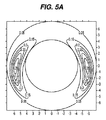
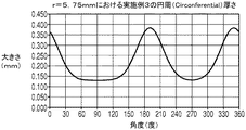
レンズ性能特性が初期設計を超える著しい改善を示すまで、ピーク位置を中心に安定ゾーンを回転させた。回転は、元の安定ゾーン座標上に座標変換(ピーク位置を中心とする回転)を適用することによって得られた。
安定ゾーンの最終配向が垂直から10.0度離れており、図5に示されるように安定の上部がレンズの中心に向いている、改善された安定化設計が得られた。更に、安定ゾーンは水平軸に関して対称でない。この場合、各ゾーンの長さの大部分は、水平軸の上方にある。メリット関数の最終値は0.58であった。メリット関数の改善はほぼ59%程度であった。回転は、初期安定化設計と比べて急速に減少した。30度未満の回転が見られるまばたき4回から始め、まばたき12回以降は回転はなく、これと比べて、初期設計では同じ範囲のまばたきにおいて約40度〜25度の回転が見られた。セントレーションは、改善された設計ではまばたき1回で0.04mm未満、及びそれ以降は0.03mm未満と安定状態を保ったが、初期設計では、同じ回数のまばたきサイクルにおいて0.06mmから0.08mm超であった。この実施例は、実施例1のレンズと比較して改善された回転、セントレーション、及び安定性を示している。 An improved stabilization design was obtained in which the final orientation of the stability zone is 10.0 degrees away from vertical and the top of the stability is toward the center of the lens as shown in FIG. Furthermore, the stability zone is not symmetrical about the horizontal axis. In this case, most of the length of each zone is above the horizontal axis. The final value of the merit function was 0.58. The improvement of the merit function was about 59%. The rotation decreased rapidly compared to the initial stabilization design. Starting with 4 blinks in which rotation of less than 30 degrees was observed, there was no rotation after 12 blinks. Compared with this, in the initial design, about 40 degrees to 25 degrees of rotation was observed in the same range of blinks. The centration remained stable at less than 0.04 mm with a single blink in the improved design and less than 0.03 mm after that, whereas in the initial design, 0.06 mm to 0. 0 in the same number of blink cycles. It was over 08 mm. This example shows improved rotation, centration, and stability compared to the lens of Example 1.
(実施例3)
上述の眼モデル及び最適化方法、並びに実施例1に記載される初期設計を用いて、新しい安定ゾーンが設計された。メリット関数は以下を用いて定義された。
−回転反応の下の表面積。
−センタリング反応の下の表面積。
−回転及びセントレーションに関して同一の重み、WR=WC=1.0。
(Example 3)
Using the eye model and optimization method described above and the initial design described in Example 1, a new stable zone was designed. The merit function was defined using:
-Surface area under the rotational reaction.
-Surface area under the centering reaction.
-Same weight for rotation and centration, W R = W C = 1.0.
最初の安定ゾーンを構成した値は次の通りであった。
−Z0=0.25mm
−r0=5.75mm
−σR=0.50mm
−θ0=左及び右の安定ゾーンに関して、それぞれ180度及び0度
−σθ=25.0度
The values constituting the first stable zone were as follows:
−Z 0 = 0.25 mm
−r 0 = 5.75 mm
−σ R = 0.50 mm
-Θ 0 = 180 degrees and 0 degrees for the left and right stability zones, respectively -σ θ = 25.0 degrees
元のレンズの厚さプロファイルに安定ゾーンを加えた。 A stability zone was added to the original lens thickness profile.
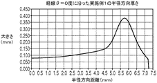
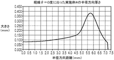
安定ゾーンの最終配向が、図6に示されるように、安定ゾーンのピーク位置がレンズの幾何学的中心から経度約0〜180度に関して角度をなして変化しているようなものである、改善された安定化設計を得た。安定ゾーンは、もはや水平軸に関して対称でなく、これらのゾーンの勾配の変化率は、経度0〜180度から離れる方向に様々である。メリット関数の最終値は0.64であった。メリット関数の改善はほぼ55%程度であった。回転は、初期安定化設計と比べて急速に減少した。30度未満の回転が見られるまばたき4回から始め、まばたき10回で約10度の回転が見られ、まばたき16回以降は回転はなく、これと比べて、初期設計では同じ範囲のまばたきにおいて約40度〜30度〜15度の回転が見られた。セントレーションは、まばたき1回で0.06mm未満、及びまばたき4回で0.04mm未満であった。その後、8回のまばたきで0.02mm未満及びまばたき16回で0mmと急速に減少し、これに比べて、初期設計では同じ回数のまばたきサイクルにおいて0.06mm超〜0.07mm超及び0.08mm超であった。この実施例は、実施例1のレンズと比較して改善された回転、セントレーション、及び安定性を示している。 The final orientation of the stable zone is such that the peak position of the stable zone is changing at an angle with respect to about 0-180 degrees longitude from the geometric center of the lens, as shown in FIG. Got the stabilized design. The stable zones are no longer symmetric with respect to the horizontal axis, and the rate of change of the slope of these zones varies in the direction away from longitude 0-180 degrees. The final value of the merit function was 0.64. The improvement of the merit function was about 55%. The rotation decreased rapidly compared to the initial stabilization design. Starting with 4 blinks with rotation less than 30 degrees, 10 blinks with 10 blinks and no rotation after 16 blinks. Compared to this, with the initial design, the blink is within the same range. A rotation of 40 degrees to 30 degrees to 15 degrees was observed. Centration was less than 0.06 mm with one blink and less than 0.04 mm with four blinks. Thereafter, it decreased rapidly to less than 0.02 mm with 8 blinks and 0 mm with 16 blinks, and compared with this, the initial design exceeded 0.06 mm to more than 0.07 mm and 0.08 mm in the same number of blink cycles. It was super. This example shows improved rotation, centration, and stability compared to the lens of Example 1.
(実施例4)
上述の眼モデル及び最適化方法、並びに実施例1に記載される初期設計を用いて、新しい安定ゾーンが設計された。メリット関数は以下を用いて定義された。
−回転反応の下の表面積。
−セントレーション反応の下の表面積。
−回転WRの重み=0.84、セントレーションWCの重み=1.14。
Example 4
Using the eye model and optimization method described above and the initial design described in Example 1, a new stable zone was designed. The merit function was defined using:
-Surface area under the rotational reaction.
The surface area under the centration reaction.
- the weight of the rotary W R = 0.84, weight = 1.14 centration W C.
最初の安定ゾーンを構成した値は次の通りであった。
−Z0=0.25mm
−r0=5.75mm
−σR=0.50mm
−θ0=1.954
−σθ=0.14
The values constituting the first stable zone were as follows:
−Z 0 = 0.25 mm
−r 0 = 5.75 mm
−σ R = 0.50 mm
−θ 0 = 1.954
−σ θ = 0.14
元のレンズの厚さプロファイルに安定ゾーンを加えた。安定ゾーンは、ピーク位置周辺の勾配を変化させるように調整された。ピーク位置は、図7に示されるように、経度0〜180度上に維持された。安定ゾーンは水平軸に関して対称でなく、これらのゾーンの勾配の変化率は、ピーク高さから離れる方向に様々である。これは、この場合では、レンズの底部に向かって勾配の減少がより緩やかになっていることによって強調されている。勾配変化は、厚さ変化を角度により記述する対数正規ガウス分布関数を用いて得た。メリット関数の最終値は0.86であった。メリット関数の改善はほぼ30%程度であった。回転は、初期安定化設計と比べて小幅に減少した。30度未満の回転が見られるまばたき6回から始め、まばたき12回で約10度の回転が見られたが、まばたき16回以降は回転はなく、これと比べて、初期設計では同じ範囲のまばたきにおいて約38度〜30度〜15度の回転が見られた。セントレーションは、まばたき1回で0.08mm未満、及びまばたき4回で0.07mm未満であった。その後、8回のまばたきで0.05mm未満及びまばたき16回で0.04mmと急速に減少し、これに比べて、初期設計では同じ回数のまばたきサイクルにおいて0.06mm〜0.07mm超及び0.08mmであった。この実施例は、実施例1のレンズと比較して改善された回転、セントレーション、及び安定性を示している。 A stability zone was added to the original lens thickness profile. The stability zone was adjusted to change the slope around the peak position. The peak position was maintained at 0 to 180 degrees longitude as shown in FIG. The stable zones are not symmetric about the horizontal axis, and the rate of change of the slope of these zones varies in the direction away from the peak height. This is emphasized in this case by the gradual decrease in slope towards the bottom of the lens. The gradient change was obtained using a lognormal Gaussian distribution function that describes the thickness change by angle. The final value of the merit function was 0.86. The improvement of the merit function was about 30%. The rotation decreased slightly compared to the initial stabilization design. Starting with 6 blinks with a rotation of less than 30 degrees and about 10 degrees with 12 blinks, there was no rotation after 16 blinks. Compared to this, the initial design blinks within the same range. A rotation of about 38 ° to 30 ° to 15 ° was observed. Centration was less than 0.08 mm with one blink and less than 0.07 mm with four blinks. Thereafter, it decreased rapidly to less than 0.05 mm with 8 blinks and 0.04 mm with 16 blinks, compared with 0.06 mm to more than 0.07 mm and 0. 0 in the same number of blink cycles in the initial design. It was 08 mm. This example shows improved rotation, centration, and stability compared to the lens of Example 1.
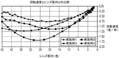
図8は、実施例1、2、3、及び4の眼上のレンズ配向と対比した回転速度を要約している。実施例1に記載された初期設計は、45°〜0°のミス配向範囲内に約−0.55°/秒の平均回転速度を有し、実施例2、3及び4における設計は、同じミス配向範囲内に−0.70°/秒を超える平均回転速度を有する。実施例2及び4は、15°未満のミス配向に関してより速い回転速度を有する。これらの設計は共に、高い収差補正を目的として設計されたソフトコンタクトレンズなど、眼上で単一配向を必要とするレンズにより適している。これらの設計は、患者がレンズを挿入するのを助けるために前面に特別な基準点を必要とする、他とは異なる適合方法を必要とする場合がある。安定化の非対称性のせいで眼上のレンズ配向が独特であるため、及び前面上の印に起因して、挿入中のレンズの配向は、レンズが静止位置に達した後のレンズの最終配向と非常に近くなければならない。挿入時のミス配向が小さくて回転速度が速いと、完全な視力矯正がより迅速にもたらされる。これらの設計はまた、実施例3を超えるより良好なセントレーション性能を提供する。レンズのセントレーションは、わずかな回数のまばたきで安定する。 FIG. 8 summarizes the rotational speed versus the lens orientation on the eye for Examples 1, 2, 3, and 4. The initial design described in Example 1 has an average rotational speed of about −0.55 ° / sec within a misorientation range of 45 ° to 0 °, and the designs in Examples 2, 3 and 4 are the same It has an average rotational speed in the misorientation range that exceeds −0.70 ° / sec. Examples 2 and 4 have faster rotational speeds for misorientation of less than 15 °. Both of these designs are more suitable for lenses that require a single orientation on the eye, such as soft contact lenses designed for high aberration correction. These designs may require a different fitting method that requires a special reference point on the front surface to help the patient insert the lens. Because of the asymmetry of stabilization, the lens orientation on the eye is unique, and due to the markings on the front surface, the orientation of the lens during insertion is the final orientation of the lens after it reaches a rest position And must be very close. If the misorientation during insertion is small and the rotational speed is fast, complete vision correction is achieved more quickly. These designs also provide better centration performance over Example 3. Lens centration stabilizes after a few blinks.
〔実施の態様〕
(1) コンタクトレンズを安定させる方法において、a)安定ゾーンパラメータの公称セットを有するレンズ設計を提供することと、b)運動量率のバランスをとることに基づいて前記レンズ設計にメリット関数を適用することと、c)安定ゾーンパラメータの公称セットを有する前記レンズ設計に前記メリット関数を適用することに基づいて、安定化が改善されたコンタクトレンズ設計を作製することと、を含む、方法。
(2) 工程b及びcが繰り返して行われる、実施態様1に記載の方法。
(3) コンタクトレンズ設計を検証するために、眼の機械的構造の影響をシミュレートする仮想モデルが使用される、実施態様2に記載の方法。
(4) まばたきが前記眼の機械的構造の1つであり、それに合わせて安定化スキームを調整する、実施態様3に記載の方法。
(5) コンタクトレンズを安定させる方法において、a)安定ゾーンパラメータの公称セットを有するレンズ設計を提供することと、b)前記レンズ設計の眼上での性能を評価することと、c)前記性能に基づいてメリット関数を計算することと、c)前記メリット関数を適用することによって前記安定ゾーンパラメータを最適化することと、を含む、方法。
(6) 仮想モデルを用いて繰り返して実施される、実施態様5に記載の方法。
(7) 前記モデルが、眼の機械的構造の影響をシミュレートする、実施態様6に記載の方法。
(8) 前記機械的構造がまばたきを含む、実施態様7に記載の方法。
(9) 実施態様1に記載の方法に従って製造されたコンタクトレンズ。
(10) 実施態様2に記載の方法に従って製造されたコンタクトレンズ。
Embodiment
(1) In a method for stabilizing a contact lens, a) providing a lens design having a nominal set of stability zone parameters; and b) applying a merit function to the lens design based on balancing momentum rates. And c) creating a contact lens design with improved stabilization based on applying the merit function to the lens design having a nominal set of stability zone parameters.
(2) The method according to
3. The method of
(4) The method of
(5) In a method for stabilizing a contact lens, a) providing a lens design having a nominal set of stability zone parameters, b) evaluating the on-eye performance of the lens design, and c) the performance. Calculating a merit function based on: and c) optimizing the stable zone parameter by applying the merit function.
(6) The method according to
7. The method of
8. The method of embodiment 7, wherein the mechanical structure includes blinking.
(9) A contact lens manufactured according to the method described in
(10) A contact lens manufactured according to the method of
(11) 実施態様3に記載の方法に従って製造されたコンタクトレンズ。
(12) 公称安定化設計と比べて安定化を改善して設計された、運動量率のバランスがとれているコンタクトレンズ。
(11) A contact lens manufactured according to the method of
(12) A contact lens with a balanced momentum rate, designed with improved stability compared to nominal stabilization design.
Claims (12)
Applications Claiming Priority (3)
| Application Number | Priority Date | Filing Date | Title |
|---|---|---|---|
| US12/641,116 US8480229B2 (en) | 2009-12-17 | 2009-12-17 | Method for stabilizing contact lenses |
| US12/641,116 | 2009-12-17 | ||
| PCT/US2010/060993 WO2011084679A1 (en) | 2009-12-17 | 2010-12-17 | Method for stabilizing contact lenses |
Related Child Applications (1)
| Application Number | Title | Priority Date | Filing Date |
|---|---|---|---|
| JP2017017332A Division JP6388971B2 (en) | 2009-12-17 | 2017-02-02 | How to stabilize contact lenses |
Publications (1)
| Publication Number | Publication Date |
|---|---|
| JP2013515280A true JP2013515280A (en) | 2013-05-02 |
Family
ID=43589634
Family Applications (2)
| Application Number | Title | Priority Date | Filing Date |
|---|---|---|---|
| JP2012544885A Pending JP2013515280A (en) | 2009-12-17 | 2010-12-17 | How to stabilize contact lenses |
| JP2017017332A Expired - Fee Related JP6388971B2 (en) | 2009-12-17 | 2017-02-02 | How to stabilize contact lenses |
Family Applications After (1)
| Application Number | Title | Priority Date | Filing Date |
|---|---|---|---|
| JP2017017332A Expired - Fee Related JP6388971B2 (en) | 2009-12-17 | 2017-02-02 | How to stabilize contact lenses |
Country Status (13)
| Country | Link |
|---|---|
| US (3) | US8480229B2 (en) |
| EP (1) | EP2513710B1 (en) |
| JP (2) | JP2013515280A (en) |
| KR (1) | KR101778509B1 (en) |
| CN (1) | CN102656506B (en) |
| AR (1) | AR079513A1 (en) |
| AU (1) | AU2010339788B2 (en) |
| BR (1) | BR112012014765A2 (en) |
| CA (1) | CA2784346C (en) |
| RU (1) | RU2562705C2 (en) |
| SG (1) | SG181623A1 (en) |
| TW (1) | TWI522674B (en) |
| WO (1) | WO2011084679A1 (en) |
Cited By (1)
| Publication number | Priority date | Publication date | Assignee | Title |
|---|---|---|---|---|
| US9091866B2 (en) | 2009-12-17 | 2015-07-28 | Johnson & Johnson Vision Care, Inc. | Stabilization of contact lenses |
Families Citing this family (13)
| Publication number | Priority date | Publication date | Assignee | Title |
|---|---|---|---|---|
| US8322851B2 (en) * | 2009-12-17 | 2012-12-04 | Johnson & Johnson Vision Care, Inc. | Stabilized contact lenses |
| US8403479B2 (en) | 2009-12-17 | 2013-03-26 | Johnson & Johnson Vision Care, Inc. | Contact lens eye model |
| US8480229B2 (en) * | 2009-12-17 | 2013-07-09 | Johnson & Johnson Vision Care, Inc. | Method for stabilizing contact lenses |
| US9316848B2 (en) * | 2013-03-15 | 2016-04-19 | Johnson & Johnson Vision Care, Inc. | Ophthalmic devices with stabilization features |
| US20160038277A1 (en) * | 2014-08-11 | 2016-02-11 | Amo Development, Llc | Optical Surface Systems and Methods for Treatment of Presbyopia and Other Vision Conditions |
| US20170115509A1 (en) * | 2014-08-20 | 2017-04-27 | Johnson & Johnson Vision Care, Inc. | High plus center treatment zone lens design and method for preventing and/or slowing myopia progression |
| US9638936B2 (en) | 2014-08-20 | 2017-05-02 | Johnson & Johnson Vision Care, Inc. | High plus treatment zone lens design for preventing and/or slowing myopia progression |
| US10379381B2 (en) * | 2015-06-08 | 2019-08-13 | Johnson & Johnson Vision Care, Inc. | Contact lens with optimized performance and method of design |
| US10739617B2 (en) | 2015-06-12 | 2020-08-11 | Johnson & Johnson Vision Care, Inc. | Comfort-optimized contact lens system for non-rotationally symmetric eye aberration |
| EP3358394A4 (en) * | 2015-10-01 | 2019-08-07 | Menicon Co., Ltd. | Contact lens |
| US10786959B2 (en) * | 2016-07-18 | 2020-09-29 | Johnson & Johnson Vision Care, Inc | Mold for contact lens with non-rotationally symmetric rim or edge |
| US11327341B2 (en) | 2019-06-14 | 2022-05-10 | Johnson & Johnson Vision Care, Inc | Toric contact lens stabilization design based on thickness gradients orthogonal to eyelid margin |
| US20230032140A1 (en) * | 2021-07-28 | 2023-02-02 | Coopervision International Limited | Methods of increased contact lens rotation and related contact lenses |
Citations (9)
| Publication number | Priority date | Publication date | Assignee | Title |
|---|---|---|---|---|
| JPS55108616A (en) * | 1978-12-29 | 1980-08-21 | Brummel Allan J | Contact lense |
| US5912719A (en) * | 1997-03-17 | 1999-06-15 | Essilor International Compagnie Generale D'optique | Contact lens with palpebral bosses |
| JPH11174388A (en) * | 1997-12-12 | 1999-07-02 | Hoya Health Care Kk | Toric contact lens |
| JP2004506925A (en) * | 2000-03-31 | 2004-03-04 | オキュラー サイエンシス インコーポレイテッド | Contact lenses with uniform horizontal thickness profile |
| JP2005534058A (en) * | 2002-07-19 | 2005-11-10 | ジョンソン・アンド・ジョンソン・ビジョン・ケア・インコーポレイテッド | Contact lens with stable angular position in the circumferential direction |
| JP2007503017A (en) * | 2003-08-20 | 2007-02-15 | ジョンソン・アンド・ジョンソン・ビジョン・ケア・インコーポレイテッド | Circumferential position stabilized contact lens |
| WO2009057709A1 (en) * | 2007-10-31 | 2009-05-07 | Hoya Corporation | Spectacle lens evaluating method, spectacle lens designing method using same, spectacle lens manufacturing method, spectacle lens manufacturing system, and spectacle lens |
| WO2009111545A2 (en) * | 2008-03-04 | 2009-09-11 | Johnson & Johnson Vision Care, Inc. | Rotationally stabilized contact lenses and methods for their design |
| JP2009237548A (en) * | 1998-09-28 | 2009-10-15 | Essilor Internatl (Cie Gen Opt) | Method for determining ophthalmic lenses |
Family Cites Families (41)
| Publication number | Priority date | Publication date | Assignee | Title |
|---|---|---|---|---|
| US4268133A (en) * | 1978-07-14 | 1981-05-19 | Bausch & Lomb Incorporated | Preferential orientation of contact lenses |
| US4618229A (en) * | 1983-07-22 | 1986-10-21 | Bausch & Lomb Incorporated | Bifocal contact lens |
| CS246212B1 (en) * | 1984-06-18 | 1986-10-16 | Otto Wichterle | Toric contact lens with centre of gravity shifted towards its border,mould for its production and method of moulds production |
| US5057578A (en) | 1990-04-10 | 1991-10-15 | E. I. Du Pont De Nemours And Company | Silicone-containing block copolymers and macromonomers |
| US5314960A (en) | 1990-04-10 | 1994-05-24 | Permeable Technologies, Inc. | Silicone-containing polymers, oxygen permeable hydrophilic contact lenses and methods for making these lenses and treating patients with visual impairment |
| DE4012478A1 (en) | 1990-04-19 | 1991-10-24 | Heinrich Woehlk Inst Fuer Cont | CONTACT LENS WITH STABILIZATION |
| US5371147A (en) | 1990-10-11 | 1994-12-06 | Permeable Technologies, Inc. | Silicone-containing acrylic star polymers, block copolymers and macromonomers |
| US5540410A (en) | 1994-06-10 | 1996-07-30 | Johnson & Johnson Vision Prod | Mold halves and molding assembly for making contact lenses |
| TW275112B (en) * | 1995-03-15 | 1996-05-01 | Ciba Geigy Ag | Rotationally stabilized contact lens and methods of lens stabilization |
| US5652638A (en) | 1995-05-04 | 1997-07-29 | Johnson & Johnson Vision Products, Inc. | Concentric annular ring lens designs for astigmatism |
| IL117937A0 (en) | 1995-05-04 | 1996-08-04 | Johnson & Johnson Vision Prod | Combined multifocal toric lens designs |
| US6241355B1 (en) * | 1996-03-29 | 2001-06-05 | Brian A. Barsky | Computer aided contact lens design and fabrication using spline surfaces |
| US6183082B1 (en) | 1998-12-21 | 2001-02-06 | Johnson & Johnson Vision Care, Inc. | Contact lenses with constant peripheral geometry |
| US6305802B1 (en) | 1999-08-11 | 2001-10-23 | Johnson & Johnson Vision Products, Inc. | System and method of integrating corneal topographic data and ocular wavefront data with primary ametropia measurements to create a soft contact lens design |
| WO2001016641A1 (en) | 1999-08-31 | 2001-03-08 | Johnson & Johnson Vision Care, Inc. | Rotationally stabilized contact lenses |
| CN100510847C (en) * | 2000-03-31 | 2009-07-08 | 库柏维景国际控股公司 | Contact lens |
| US6474814B1 (en) | 2000-09-08 | 2002-11-05 | Florida Optical Engineering, Inc | Multifocal ophthalmic lens with induced aperture |
| US6554425B1 (en) | 2000-10-17 | 2003-04-29 | Johnson & Johnson Vision Care, Inc. | Ophthalmic lenses for high order aberration correction and processes for production of the lenses |
| CN1511270A (en) * | 2001-04-26 | 2004-07-07 | Hoya��ʽ���� | Eyeglass lens designing method and eyeglass lens |
| JP2004534964A (en) * | 2001-04-27 | 2004-11-18 | ノバルティス アクチエンゲゼルシャフト | Automatic lens design and manufacturing system |
| JP2003126040A (en) * | 2001-10-19 | 2003-05-07 | Menicon Co Ltd | Apparatus for evaluating compatibility of contact lens and method for evaluating compatibility |
| US7896916B2 (en) | 2002-11-29 | 2011-03-01 | Amo Groningen B.V. | Multifocal ophthalmic lens |
| US7063422B2 (en) * | 2003-04-16 | 2006-06-20 | Novartis Ag | Multifocal ophthalmic lens |
| AU2003902102A0 (en) | 2003-05-02 | 2003-05-22 | The Institute For Eye Research | Contact lens |
| US6988800B2 (en) * | 2004-01-06 | 2006-01-24 | St. Shine Optical Co., Ltd. | Toric contact lens with meniscus-shaped flattened top and bottom zones for dynamic stabilization |
| US6955433B1 (en) | 2004-06-17 | 2005-10-18 | Johnson & Johnson Vision Care, Inc. | Methods for designing composite ophthalmic lens surfaces |
| CA2575028A1 (en) * | 2004-08-04 | 2006-02-09 | Novartis Ag | Soft contact lenses with stiffening rib features therein |
| DE502006000170D1 (en) * | 2005-02-08 | 2007-12-27 | Luk Lamellen & Kupplungsbau | Device for suspension and level adjustment in motor vehicles |
| CA2594432C (en) * | 2005-02-14 | 2014-08-19 | Sylvain Monette | Method and nodes for performing bridging of data traffic over an access domain |
| TW200630662A (en) * | 2005-02-23 | 2006-09-01 | Novartis Ag | A toric lens design |
| GB2426812B (en) * | 2005-06-03 | 2009-11-25 | Contact Lens Prec Lab Ltd | Improvements in or relating to contact lenses |
| US7216978B2 (en) * | 2005-06-08 | 2007-05-15 | Johnson & Johnson Vision Care, Inc. | Method for evaluating eyelid movement and contact lens position |
| US7296890B2 (en) | 2005-10-25 | 2007-11-20 | Truform Optics | Contact lens with controlled shape |
| JP2008083083A (en) * | 2006-09-25 | 2008-04-10 | Kyocera Corp | Tolerance determining device, tolerance determining method, program, and recording medium |
| US7862169B2 (en) | 2006-09-29 | 2011-01-04 | Johnson & Johnson Vision Care, Inc. | Contact lenses and methods for their design |
| JP5490546B2 (en) * | 2007-01-25 | 2014-05-14 | ローデンストック.ゲゼルシャフト.ミット.ベシュレンクテル.ハフツング | Method for optimizing spectacle lenses |
| AU2008332369B2 (en) * | 2007-12-04 | 2011-09-08 | Hoya Corporation | Pair of progressive power lens and method for designing same |
| US8322851B2 (en) * | 2009-12-17 | 2012-12-04 | Johnson & Johnson Vision Care, Inc. | Stabilized contact lenses |
| US8439499B2 (en) * | 2009-12-17 | 2013-05-14 | Johnson & Johnson Vision Care, Inc. | Method for producing stabilized contact lenses |
| US8480229B2 (en) * | 2009-12-17 | 2013-07-09 | Johnson & Johnson Vision Care, Inc. | Method for stabilizing contact lenses |
| US8403479B2 (en) * | 2009-12-17 | 2013-03-26 | Johnson & Johnson Vision Care, Inc. | Contact lens eye model |
-
2009
- 2009-12-17 US US12/641,116 patent/US8480229B2/en active Active
-
2010
- 2010-12-16 TW TW099144123A patent/TWI522674B/en not_active IP Right Cessation
- 2010-12-17 JP JP2012544885A patent/JP2013515280A/en active Pending
- 2010-12-17 CA CA2784346A patent/CA2784346C/en not_active Expired - Fee Related
- 2010-12-17 AU AU2010339788A patent/AU2010339788B2/en not_active Ceased
- 2010-12-17 EP EP10801509.0A patent/EP2513710B1/en not_active Not-in-force
- 2010-12-17 BR BR112012014765-0A patent/BR112012014765A2/en not_active Application Discontinuation
- 2010-12-17 SG SG2012042727A patent/SG181623A1/en unknown
- 2010-12-17 CN CN201080057271.0A patent/CN102656506B/en not_active Expired - Fee Related
- 2010-12-17 WO PCT/US2010/060993 patent/WO2011084679A1/en active Application Filing
- 2010-12-17 AR ARP100104727 patent/AR079513A1/en not_active Application Discontinuation
- 2010-12-17 RU RU2012130163/28A patent/RU2562705C2/en not_active IP Right Cessation
- 2010-12-17 KR KR1020127018089A patent/KR101778509B1/en active IP Right Grant
-
2013
- 2013-06-05 US US13/910,332 patent/US9134545B2/en not_active Expired - Fee Related
-
2015
- 2015-08-13 US US14/825,270 patent/US9791716B2/en active Active
-
2017
- 2017-02-02 JP JP2017017332A patent/JP6388971B2/en not_active Expired - Fee Related
Patent Citations (10)
| Publication number | Priority date | Publication date | Assignee | Title |
|---|---|---|---|---|
| JPS55108616A (en) * | 1978-12-29 | 1980-08-21 | Brummel Allan J | Contact lense |
| US5912719A (en) * | 1997-03-17 | 1999-06-15 | Essilor International Compagnie Generale D'optique | Contact lens with palpebral bosses |
| JPH11174388A (en) * | 1997-12-12 | 1999-07-02 | Hoya Health Care Kk | Toric contact lens |
| JP2009237548A (en) * | 1998-09-28 | 2009-10-15 | Essilor Internatl (Cie Gen Opt) | Method for determining ophthalmic lenses |
| JP2004506925A (en) * | 2000-03-31 | 2004-03-04 | オキュラー サイエンシス インコーポレイテッド | Contact lenses with uniform horizontal thickness profile |
| JP2005534058A (en) * | 2002-07-19 | 2005-11-10 | ジョンソン・アンド・ジョンソン・ビジョン・ケア・インコーポレイテッド | Contact lens with stable angular position in the circumferential direction |
| JP2007503017A (en) * | 2003-08-20 | 2007-02-15 | ジョンソン・アンド・ジョンソン・ビジョン・ケア・インコーポレイテッド | Circumferential position stabilized contact lens |
| WO2009057709A1 (en) * | 2007-10-31 | 2009-05-07 | Hoya Corporation | Spectacle lens evaluating method, spectacle lens designing method using same, spectacle lens manufacturing method, spectacle lens manufacturing system, and spectacle lens |
| WO2009111545A2 (en) * | 2008-03-04 | 2009-09-11 | Johnson & Johnson Vision Care, Inc. | Rotationally stabilized contact lenses and methods for their design |
| JP2011513792A (en) * | 2008-03-04 | 2011-04-28 | ジョンソン・アンド・ジョンソン・ビジョン・ケア・インコーポレイテッド | Rotationally stabilized contact lens and design method thereof |
Non-Patent Citations (1)
| Title |
|---|
| JPN6014036615; Grant R.: 'Mechanics of Toric Soft Lens Stabilization' JOURNAL OF THE BRITISH CONTACT LENS ASSOCIATION 第9巻,補填1, 19860101, 第44-47頁, ELSEVIER社 * |
Cited By (2)
| Publication number | Priority date | Publication date | Assignee | Title |
|---|---|---|---|---|
| US9091866B2 (en) | 2009-12-17 | 2015-07-28 | Johnson & Johnson Vision Care, Inc. | Stabilization of contact lenses |
| US9383592B2 (en) | 2009-12-17 | 2016-07-05 | Johnson & Johnson Vision Care, Inc. | Stabilization of contact lenses |
Also Published As
| Publication number | Publication date |
|---|---|
| AU2010339788B2 (en) | 2015-03-12 |
| US9791716B2 (en) | 2017-10-17 |
| AU2010339788A1 (en) | 2012-06-28 |
| WO2011084679A1 (en) | 2011-07-14 |
| CN102656506A (en) | 2012-09-05 |
| TWI522674B (en) | 2016-02-21 |
| CA2784346C (en) | 2018-07-10 |
| TW201126229A (en) | 2011-08-01 |
| US20110149231A1 (en) | 2011-06-23 |
| US20130335698A1 (en) | 2013-12-19 |
| SG181623A1 (en) | 2012-07-30 |
| EP2513710A1 (en) | 2012-10-24 |
| JP6388971B2 (en) | 2018-09-12 |
| US8480229B2 (en) | 2013-07-09 |
| KR101778509B1 (en) | 2017-09-15 |
| KR20120102770A (en) | 2012-09-18 |
| US20150346514A1 (en) | 2015-12-03 |
| AR079513A1 (en) | 2012-02-01 |
| CA2784346A1 (en) | 2011-07-14 |
| RU2012130163A (en) | 2014-01-27 |
| CN102656506B (en) | 2014-07-09 |
| RU2562705C2 (en) | 2015-09-10 |
| BR112012014765A2 (en) | 2020-09-08 |
| US9134545B2 (en) | 2015-09-15 |
| JP2017083904A (en) | 2017-05-18 |
| EP2513710B1 (en) | 2017-01-25 |
Similar Documents
| Publication | Publication Date | Title |
|---|---|---|
| JP6388971B2 (en) | How to stabilize contact lenses | |
| JP2013515278A (en) | Contact lens with stabilizing features | |
| JP5914352B2 (en) | Contact lens stabilization | |
| JP6000853B2 (en) | Method for manufacturing a stabilized contact lens | |
| KR101778511B1 (en) | Stabilized contact lenses | |
| AU2015201838B2 (en) | Method for stabilizing contact lenses |
Legal Events
| Date | Code | Title | Description |
|---|---|---|---|
| A621 | Written request for application examination |
Free format text: JAPANESE INTERMEDIATE CODE: A621 Effective date: 20131119 |
|
| A977 | Report on retrieval |
Free format text: JAPANESE INTERMEDIATE CODE: A971007 Effective date: 20140813 |
|
| A131 | Notification of reasons for refusal |
Free format text: JAPANESE INTERMEDIATE CODE: A131 Effective date: 20140902 |
|
| A601 | Written request for extension of time |
Free format text: JAPANESE INTERMEDIATE CODE: A601 Effective date: 20141202 |
|
| A602 | Written permission of extension of time |
Free format text: JAPANESE INTERMEDIATE CODE: A602 Effective date: 20141209 |
|
| A521 | Request for written amendment filed |
Free format text: JAPANESE INTERMEDIATE CODE: A523 Effective date: 20141212 |
|
| A02 | Decision of refusal |
Free format text: JAPANESE INTERMEDIATE CODE: A02 Effective date: 20150331 |
|
| A521 | Request for written amendment filed |
Free format text: JAPANESE INTERMEDIATE CODE: A523 Effective date: 20150731 |
|
| A911 | Transfer to examiner for re-examination before appeal (zenchi) |
Free format text: JAPANESE INTERMEDIATE CODE: A911 Effective date: 20150807 |
|
| A912 | Re-examination (zenchi) completed and case transferred to appeal board |
Free format text: JAPANESE INTERMEDIATE CODE: A912 Effective date: 20151030 |
|
| A601 | Written request for extension of time |
Free format text: JAPANESE INTERMEDIATE CODE: A601 Effective date: 20161102 |
|
| A601 | Written request for extension of time |
Free format text: JAPANESE INTERMEDIATE CODE: A601 Effective date: 20161202 |
|
| A601 | Written request for extension of time |
Free format text: JAPANESE INTERMEDIATE CODE: A601 Effective date: 20161228 |
|
| A521 | Request for written amendment filed |
Free format text: JAPANESE INTERMEDIATE CODE: A523 Effective date: 20170202 |