JP2013512311A - Aqueous production process for crystalline copper chalcogenide nanoparticles, nanoparticles so produced, and inks and coated substrates incorporating these nanoparticles - Google Patents
Aqueous production process for crystalline copper chalcogenide nanoparticles, nanoparticles so produced, and inks and coated substrates incorporating these nanoparticles Download PDFInfo
- Publication number
- JP2013512311A JP2013512311A JP2012541134A JP2012541134A JP2013512311A JP 2013512311 A JP2013512311 A JP 2013512311A JP 2012541134 A JP2012541134 A JP 2012541134A JP 2012541134 A JP2012541134 A JP 2012541134A JP 2013512311 A JP2013512311 A JP 2013512311A
- Authority
- JP
- Japan
- Prior art keywords
- metal chalcogenide
- nanoparticles
- metal
- selenide
- sulfide
- Prior art date
- Legal status (The legal status is an assumption and is not a legal conclusion. Google has not performed a legal analysis and makes no representation as to the accuracy of the status listed.)
- Withdrawn
Links
- 239000002105 nanoparticle Substances 0.000 title claims abstract description 125
- 239000000758 substrate Substances 0.000 title claims description 50
- -1 copper chalcogenide Chemical class 0.000 title claims description 6
- 238000004519 manufacturing process Methods 0.000 title abstract description 9
- 239000010949 copper Substances 0.000 title description 41
- 239000000976 ink Substances 0.000 title description 36
- 229910052802 copper Inorganic materials 0.000 title description 13
- 229910052751 metal Inorganic materials 0.000 claims abstract description 243
- 239000002184 metal Substances 0.000 claims abstract description 243
- 150000004770 chalcogenides Chemical class 0.000 claims abstract description 189
- 239000002245 particle Substances 0.000 claims abstract description 107
- 238000000034 method Methods 0.000 claims abstract description 57
- WILFBXOGIULNAF-UHFFFAOYSA-N copper sulfanylidenetin zinc Chemical compound [Sn]=S.[Zn].[Cu] WILFBXOGIULNAF-UHFFFAOYSA-N 0.000 claims abstract description 11
- SEAVSGQBBULBCJ-UHFFFAOYSA-N [Sn]=S.[Cu] Chemical compound [Sn]=S.[Cu] SEAVSGQBBULBCJ-UHFFFAOYSA-N 0.000 claims abstract description 10
- 239000010410 layer Substances 0.000 claims description 74
- 239000000203 mixture Chemical class 0.000 claims description 55
- 238000010438 heat treatment Methods 0.000 claims description 39
- 238000000576 coating method Methods 0.000 claims description 30
- 239000000463 material Substances 0.000 claims description 30
- 239000011541 reaction mixture Substances 0.000 claims description 28
- 239000011248 coating agent Substances 0.000 claims description 27
- 239000003446 ligand Substances 0.000 claims description 25
- 150000003346 selenoethers Chemical class 0.000 claims description 24
- 150000003839 salts Chemical class 0.000 claims description 23
- 239000007864 aqueous solution Substances 0.000 claims description 21
- 229910052798 chalcogen Inorganic materials 0.000 claims description 20
- 150000001787 chalcogens Chemical class 0.000 claims description 20
- XLYOFNOQVPJJNP-UHFFFAOYSA-N water Substances O XLYOFNOQVPJJNP-UHFFFAOYSA-N 0.000 claims description 19
- 239000012530 fluid Substances 0.000 claims description 18
- 239000002609 medium Substances 0.000 claims description 17
- 238000000151 deposition Methods 0.000 claims description 14
- 150000001875 compounds Chemical class 0.000 claims description 11
- 238000003756 stirring Methods 0.000 claims description 11
- QGZKDVFQNNGYKY-UHFFFAOYSA-N Ammonia Chemical compound N QGZKDVFQNNGYKY-UHFFFAOYSA-N 0.000 claims description 10
- UCKMPCXJQFINFW-UHFFFAOYSA-N Sulphide Chemical compound [S-2] UCKMPCXJQFINFW-UHFFFAOYSA-N 0.000 claims description 10
- 239000002585 base Substances 0.000 claims description 9
- 239000004094 surface-active agent Substances 0.000 claims description 8
- 150000001412 amines Chemical class 0.000 claims description 7
- 229910052733 gallium Inorganic materials 0.000 claims description 7
- 150000003573 thiols Chemical class 0.000 claims description 6
- 229910021529 ammonia Inorganic materials 0.000 claims description 5
- 239000002270 dispersing agent Substances 0.000 claims description 5
- 150000004820 halides Chemical class 0.000 claims description 5
- 150000007524 organic acids Chemical class 0.000 claims description 5
- 235000005985 organic acids Nutrition 0.000 claims description 5
- GYSDUVRPSWKYDJ-UHFFFAOYSA-N selinone Chemical compound C1=CC(OCC=C(C)C)=CC=C1C1OC2=CC(O)=CC(O)=C2C(=O)C1 GYSDUVRPSWKYDJ-UHFFFAOYSA-N 0.000 claims description 5
- 239000000654 additive Substances 0.000 claims description 4
- 239000011230 binding agent Substances 0.000 claims description 4
- LCUOIYYHNRBAFS-UHFFFAOYSA-N copper;sulfanylideneindium Chemical compound [Cu].[In]=S LCUOIYYHNRBAFS-UHFFFAOYSA-N 0.000 claims description 4
- 239000002019 doping agent Substances 0.000 claims description 4
- 150000003958 selenols Chemical class 0.000 claims description 4
- GYHNNYVSQQEPJS-UHFFFAOYSA-N Gallium Chemical compound [Ga] GYHNNYVSQQEPJS-UHFFFAOYSA-N 0.000 claims description 3
- 150000003863 ammonium salts Chemical class 0.000 claims description 3
- 150000001879 copper Chemical class 0.000 claims description 3
- HVMJUDPAXRRVQO-UHFFFAOYSA-N copper indium Chemical compound [Cu].[In] HVMJUDPAXRRVQO-UHFFFAOYSA-N 0.000 claims description 3
- 239000007788 liquid Substances 0.000 claims description 3
- RWSOTUBLDIXVET-UHFFFAOYSA-N Dihydrogen sulfide Chemical compound S RWSOTUBLDIXVET-UHFFFAOYSA-N 0.000 claims description 2
- 241001061127 Thione Species 0.000 claims description 2
- ATJFFYVFTNAWJD-UHFFFAOYSA-N Tin Chemical class [Sn] ATJFFYVFTNAWJD-UHFFFAOYSA-N 0.000 claims description 2
- 229910021626 Tin(II) chloride Inorganic materials 0.000 claims description 2
- 150000001242 acetic acid derivatives Chemical class 0.000 claims description 2
- 150000001298 alcohols Chemical class 0.000 claims description 2
- 150000001335 aliphatic alkanes Chemical class 0.000 claims description 2
- 229910052977 alkali metal sulfide Inorganic materials 0.000 claims description 2
- 150000001408 amides Chemical class 0.000 claims description 2
- 239000002518 antifoaming agent Substances 0.000 claims description 2
- 150000001735 carboxylic acids Chemical class 0.000 claims description 2
- TVZPLCNGKSPOJA-UHFFFAOYSA-N copper zinc Chemical compound [Cu].[Zn] TVZPLCNGKSPOJA-UHFFFAOYSA-N 0.000 claims description 2
- 150000002148 esters Chemical class 0.000 claims description 2
- 150000002170 ethers Chemical class 0.000 claims description 2
- 229910000037 hydrogen sulfide Inorganic materials 0.000 claims description 2
- 150000002576 ketones Chemical class 0.000 claims description 2
- 150000002825 nitriles Chemical class 0.000 claims description 2
- 150000003751 zinc Chemical class 0.000 claims description 2
- 229910052783 alkali metal Inorganic materials 0.000 claims 1
- 239000006117 anti-reflective coating Substances 0.000 claims 1
- 150000001491 aromatic compounds Chemical class 0.000 claims 1
- 125000006615 aromatic heterocyclic group Chemical group 0.000 claims 1
- 150000002258 gallium Chemical class 0.000 claims 1
- 150000002471 indium Chemical class 0.000 claims 1
- SPVXKVOXSXTJOY-UHFFFAOYSA-N selane Chemical compound [SeH2] SPVXKVOXSXTJOY-UHFFFAOYSA-N 0.000 claims 1
- 229910000058 selane Inorganic materials 0.000 claims 1
- 239000004071 soot Substances 0.000 claims 1
- 239000002243 precursor Substances 0.000 abstract description 12
- 150000004771 selenides Chemical class 0.000 abstract 2
- 239000010408 film Substances 0.000 description 47
- IJGRMHOSHXDMSA-UHFFFAOYSA-N Atomic nitrogen Chemical compound N#N IJGRMHOSHXDMSA-UHFFFAOYSA-N 0.000 description 30
- 229910052717 sulfur Inorganic materials 0.000 description 29
- 239000012298 atmosphere Substances 0.000 description 25
- 230000015572 biosynthetic process Effects 0.000 description 22
- 239000011669 selenium Substances 0.000 description 22
- NINIDFKCEFEMDL-UHFFFAOYSA-N Sulfur Chemical compound [S] NINIDFKCEFEMDL-UHFFFAOYSA-N 0.000 description 21
- 239000011593 sulfur Substances 0.000 description 20
- 238000000137 annealing Methods 0.000 description 17
- 239000010409 thin film Substances 0.000 description 17
- OKKJLVBELUTLKV-UHFFFAOYSA-N Methanol Chemical compound OC OKKJLVBELUTLKV-UHFFFAOYSA-N 0.000 description 16
- 210000004027 cell Anatomy 0.000 description 16
- 239000003795 chemical substances by application Substances 0.000 description 16
- 238000002474 experimental method Methods 0.000 description 16
- 229910052757 nitrogen Inorganic materials 0.000 description 16
- 239000000523 sample Substances 0.000 description 16
- 239000000243 solution Substances 0.000 description 16
- 239000000843 powder Substances 0.000 description 14
- 239000004065 semiconductor Substances 0.000 description 14
- 238000003786 synthesis reaction Methods 0.000 description 14
- HEMHJVSKTPXQMS-UHFFFAOYSA-M Sodium hydroxide Chemical compound [OH-].[Na+] HEMHJVSKTPXQMS-UHFFFAOYSA-M 0.000 description 12
- XLOMVQKBTHCTTD-UHFFFAOYSA-N Zinc monoxide Chemical compound [Zn]=O XLOMVQKBTHCTTD-UHFFFAOYSA-N 0.000 description 12
- 238000004458 analytical method Methods 0.000 description 12
- 238000004140 cleaning Methods 0.000 description 12
- 238000009826 distribution Methods 0.000 description 12
- 239000011135 tin Substances 0.000 description 12
- 150000002739 metals Chemical class 0.000 description 11
- 229910052711 selenium Inorganic materials 0.000 description 11
- 239000007787 solid Substances 0.000 description 11
- 239000011701 zinc Substances 0.000 description 11
- HZAXFHJVJLSVMW-UHFFFAOYSA-N 2-Aminoethan-1-ol Chemical compound NCCO HZAXFHJVJLSVMW-UHFFFAOYSA-N 0.000 description 10
- GSEJCLTVZPLZKY-UHFFFAOYSA-N Triethanolamine Chemical compound OCCN(CCO)CCO GSEJCLTVZPLZKY-UHFFFAOYSA-N 0.000 description 10
- UMGDCJDMYOKAJW-UHFFFAOYSA-N thiourea Chemical compound NC(N)=S UMGDCJDMYOKAJW-UHFFFAOYSA-N 0.000 description 10
- WEVYAHXRMPXWCK-UHFFFAOYSA-N Acetonitrile Chemical compound CC#N WEVYAHXRMPXWCK-UHFFFAOYSA-N 0.000 description 9
- 238000006243 chemical reaction Methods 0.000 description 9
- 239000011521 glass Substances 0.000 description 9
- YUKQRDCYNOVPGJ-UHFFFAOYSA-N thioacetamide Chemical compound CC(N)=S YUKQRDCYNOVPGJ-UHFFFAOYSA-N 0.000 description 9
- DLFVBJFMPXGRIB-UHFFFAOYSA-N thioacetamide Natural products CC(N)=O DLFVBJFMPXGRIB-UHFFFAOYSA-N 0.000 description 9
- JUJWROOIHBZHMG-UHFFFAOYSA-N Pyridine Chemical compound C1=CC=NC=C1 JUJWROOIHBZHMG-UHFFFAOYSA-N 0.000 description 8
- 239000002253 acid Substances 0.000 description 8
- 239000006227 byproduct Substances 0.000 description 8
- VKYKSIONXSXAKP-UHFFFAOYSA-N hexamethylenetetramine Chemical compound C1N(C2)CN3CN1CN2C3 VKYKSIONXSXAKP-UHFFFAOYSA-N 0.000 description 8
- CWERGRDVMFNCDR-UHFFFAOYSA-N thioglycolic acid Chemical compound OC(=O)CS CWERGRDVMFNCDR-UHFFFAOYSA-N 0.000 description 8
- 229910052718 tin Inorganic materials 0.000 description 8
- 229910052980 cadmium sulfide Inorganic materials 0.000 description 7
- 239000013078 crystal Substances 0.000 description 7
- 239000012535 impurity Substances 0.000 description 7
- 229910052709 silver Inorganic materials 0.000 description 7
- CSCPPACGZOOCGX-UHFFFAOYSA-N Acetone Chemical compound CC(C)=O CSCPPACGZOOCGX-UHFFFAOYSA-N 0.000 description 6
- ZOKXTWBITQBERF-UHFFFAOYSA-N Molybdenum Chemical compound [Mo] ZOKXTWBITQBERF-UHFFFAOYSA-N 0.000 description 6
- QAOWNCQODCNURD-UHFFFAOYSA-N Sulfuric acid Chemical compound OS(O)(=O)=O QAOWNCQODCNURD-UHFFFAOYSA-N 0.000 description 6
- YXFVVABEGXRONW-UHFFFAOYSA-N Toluene Chemical compound CC1=CC=CC=C1 YXFVVABEGXRONW-UHFFFAOYSA-N 0.000 description 6
- ZMANZCXQSJIPKH-UHFFFAOYSA-N Triethylamine Chemical compound CCN(CC)CC ZMANZCXQSJIPKH-UHFFFAOYSA-N 0.000 description 6
- 239000003153 chemical reaction reagent Substances 0.000 description 6
- 239000004020 conductor Substances 0.000 description 6
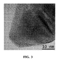
- 238000002173 high-resolution transmission electron microscopy Methods 0.000 description 6
- 229910052750 molybdenum Inorganic materials 0.000 description 6
- 239000011733 molybdenum Substances 0.000 description 6
- 239000011734 sodium Substances 0.000 description 6
- 239000000126 substance Substances 0.000 description 6
- 229910052725 zinc Inorganic materials 0.000 description 6
- 239000011787 zinc oxide Substances 0.000 description 6
- PIICEJLVQHRZGT-UHFFFAOYSA-N Ethylenediamine Chemical compound NCCN PIICEJLVQHRZGT-UHFFFAOYSA-N 0.000 description 5
- BUGBHKTXTAQXES-UHFFFAOYSA-N Selenium Chemical compound [Se] BUGBHKTXTAQXES-UHFFFAOYSA-N 0.000 description 5
- 229910005642 SnTe Inorganic materials 0.000 description 5
- XSQUKJJJFZCRTK-UHFFFAOYSA-N Urea Natural products NC(N)=O XSQUKJJJFZCRTK-UHFFFAOYSA-N 0.000 description 5
- 229910052793 cadmium Inorganic materials 0.000 description 5
- KUNSUQLRTQLHQQ-UHFFFAOYSA-N copper tin Chemical compound [Cu].[Sn] KUNSUQLRTQLHQQ-UHFFFAOYSA-N 0.000 description 5
- 239000006185 dispersion Substances 0.000 description 5
- 238000001035 drying Methods 0.000 description 5
- 229910052732 germanium Inorganic materials 0.000 description 5
- 229910052738 indium Inorganic materials 0.000 description 5
- 150000002500 ions Chemical class 0.000 description 5
- 239000000047 product Substances 0.000 description 5
- 238000000926 separation method Methods 0.000 description 5
- 229910052710 silicon Inorganic materials 0.000 description 5
- 238000000235 small-angle X-ray scattering Methods 0.000 description 5
- 239000005361 soda-lime glass Substances 0.000 description 5
- 238000005507 spraying Methods 0.000 description 5
- 238000004544 sputter deposition Methods 0.000 description 5
- 238000005406 washing Methods 0.000 description 5
- BSKHPKMHTQYZBB-UHFFFAOYSA-N 2-methylpyridine Chemical compound CC1=CC=CC=N1 BSKHPKMHTQYZBB-UHFFFAOYSA-N 0.000 description 4
- HWWYDZCSSYKIAD-UHFFFAOYSA-N 3,5-dimethylpyridine Chemical compound CC1=CN=CC(C)=C1 HWWYDZCSSYKIAD-UHFFFAOYSA-N 0.000 description 4
- ITQTTZVARXURQS-UHFFFAOYSA-N 3-methylpyridine Chemical compound CC1=CC=CN=C1 ITQTTZVARXURQS-UHFFFAOYSA-N 0.000 description 4
- LFQSCWFLJHTTHZ-UHFFFAOYSA-N Ethanol Chemical compound CCO LFQSCWFLJHTTHZ-UHFFFAOYSA-N 0.000 description 4
- MHAJPDPJQMAIIY-UHFFFAOYSA-N Hydrogen peroxide Chemical compound OO MHAJPDPJQMAIIY-UHFFFAOYSA-N 0.000 description 4
- WYURNTSHIVDZCO-UHFFFAOYSA-N Tetrahydrofuran Chemical compound C1CCOC1 WYURNTSHIVDZCO-UHFFFAOYSA-N 0.000 description 4
- 238000002056 X-ray absorption spectroscopy Methods 0.000 description 4
- ITBPIKUGMIZTJR-UHFFFAOYSA-N [bis(hydroxymethyl)amino]methanol Chemical compound OCN(CO)CO ITBPIKUGMIZTJR-UHFFFAOYSA-N 0.000 description 4
- 150000007513 acids Chemical class 0.000 description 4
- 229910052782 aluminium Inorganic materials 0.000 description 4
- 230000008901 benefit Effects 0.000 description 4
- 230000002902 bimodal effect Effects 0.000 description 4
- 229910052799 carbon Inorganic materials 0.000 description 4
- 230000008021 deposition Effects 0.000 description 4
- ZBCBWPMODOFKDW-UHFFFAOYSA-N diethanolamine Chemical compound OCCNCCO ZBCBWPMODOFKDW-UHFFFAOYSA-N 0.000 description 4
- 239000004312 hexamethylene tetramine Substances 0.000 description 4
- 235000010299 hexamethylene tetramine Nutrition 0.000 description 4
- 230000003287 optical effect Effects 0.000 description 4
- 229920000036 polyvinylpyrrolidone Polymers 0.000 description 4
- 235000013855 polyvinylpyrrolidone Nutrition 0.000 description 4
- UMJSCPRVCHMLSP-UHFFFAOYSA-N pyridine Natural products COC1=CC=CN=C1 UMJSCPRVCHMLSP-UHFFFAOYSA-N 0.000 description 4
- 239000010453 quartz Substances 0.000 description 4
- VYPSYNLAJGMNEJ-UHFFFAOYSA-N silicon dioxide Inorganic materials O=[Si]=O VYPSYNLAJGMNEJ-UHFFFAOYSA-N 0.000 description 4
- 238000010561 standard procedure Methods 0.000 description 4
- 229910052714 tellurium Inorganic materials 0.000 description 4
- DAFHKNAQFPVRKR-UHFFFAOYSA-N (3-hydroxy-2,2,4-trimethylpentyl) 2-methylpropanoate Chemical compound CC(C)C(O)C(C)(C)COC(=O)C(C)C DAFHKNAQFPVRKR-UHFFFAOYSA-N 0.000 description 3
- WUOACPNHFRMFPN-SECBINFHSA-N (S)-(-)-alpha-terpineol Chemical compound CC1=CC[C@@H](C(C)(C)O)CC1 WUOACPNHFRMFPN-SECBINFHSA-N 0.000 description 3
- QGLWBTPVKHMVHM-KTKRTIGZSA-N (z)-octadec-9-en-1-amine Chemical compound CCCCCCCC\C=C/CCCCCCCCN QGLWBTPVKHMVHM-KTKRTIGZSA-N 0.000 description 3
- RFFLAFLAYFXFSW-UHFFFAOYSA-N 1,2-dichlorobenzene Chemical compound ClC1=CC=CC=C1Cl RFFLAFLAYFXFSW-UHFFFAOYSA-N 0.000 description 3
- PAWQVTBBRAZDMG-UHFFFAOYSA-N 2-(3-bromo-2-fluorophenyl)acetic acid Chemical compound OC(=O)CC1=CC=CC(Br)=C1F PAWQVTBBRAZDMG-UHFFFAOYSA-N 0.000 description 3
- QTBSBXVTEAMEQO-UHFFFAOYSA-N Acetic acid Chemical compound CC(O)=O QTBSBXVTEAMEQO-UHFFFAOYSA-N 0.000 description 3
- YMWUJEATGCHHMB-UHFFFAOYSA-N Dichloromethane Chemical compound ClCCl YMWUJEATGCHHMB-UHFFFAOYSA-N 0.000 description 3
- RTZKZFJDLAIYFH-UHFFFAOYSA-N Diethyl ether Chemical compound CCOCC RTZKZFJDLAIYFH-UHFFFAOYSA-N 0.000 description 3
- KCXVZYZYPLLWCC-UHFFFAOYSA-N EDTA Chemical compound OC(=O)CN(CC(O)=O)CCN(CC(O)=O)CC(O)=O KCXVZYZYPLLWCC-UHFFFAOYSA-N 0.000 description 3
- XEKOWRVHYACXOJ-UHFFFAOYSA-N Ethyl acetate Chemical compound CCOC(C)=O XEKOWRVHYACXOJ-UHFFFAOYSA-N 0.000 description 3
- XEEYBQQBJWHFJM-UHFFFAOYSA-N Iron Chemical compound [Fe] XEEYBQQBJWHFJM-UHFFFAOYSA-N 0.000 description 3
- KWYHDKDOAIKMQN-UHFFFAOYSA-N N,N,N',N'-tetramethylethylenediamine Chemical compound CN(C)CCN(C)C KWYHDKDOAIKMQN-UHFFFAOYSA-N 0.000 description 3
- ZMXDDKWLCZADIW-UHFFFAOYSA-N N,N-Dimethylformamide Chemical compound CN(C)C=O ZMXDDKWLCZADIW-UHFFFAOYSA-N 0.000 description 3
- 238000003917 TEM image Methods 0.000 description 3
- 239000006096 absorbing agent Substances 0.000 description 3
- OVKDFILSBMEKLT-UHFFFAOYSA-N alpha-Terpineol Natural products CC(=C)C1(O)CCC(C)=CC1 OVKDFILSBMEKLT-UHFFFAOYSA-N 0.000 description 3
- 238000000231 atomic layer deposition Methods 0.000 description 3
- 238000005119 centrifugation Methods 0.000 description 3
- 239000000919 ceramic Substances 0.000 description 3
- 238000012512 characterization method Methods 0.000 description 3
- 238000000224 chemical solution deposition Methods 0.000 description 3
- OMZSGWSJDCOLKM-UHFFFAOYSA-N copper(II) sulfide Chemical compound [S-2].[Cu+2] OMZSGWSJDCOLKM-UHFFFAOYSA-N 0.000 description 3
- 239000008367 deionised water Substances 0.000 description 3
- 229910021641 deionized water Inorganic materials 0.000 description 3
- WNAHIZMDSQCWRP-UHFFFAOYSA-N dodecane-1-thiol Chemical compound CCCCCCCCCCCCS WNAHIZMDSQCWRP-UHFFFAOYSA-N 0.000 description 3
- DNJIEGIFACGWOD-UHFFFAOYSA-N ethyl mercaptane Natural products CCS DNJIEGIFACGWOD-UHFFFAOYSA-N 0.000 description 3
- 239000007789 gas Substances 0.000 description 3
- VLKZOEOYAKHREP-UHFFFAOYSA-N n-Hexane Chemical compound CCCCCC VLKZOEOYAKHREP-UHFFFAOYSA-N 0.000 description 3
- 239000012299 nitrogen atmosphere Substances 0.000 description 3
- 229920000642 polymer Polymers 0.000 description 3
- 238000000634 powder X-ray diffraction Methods 0.000 description 3
- 239000010944 silver (metal) Substances 0.000 description 3
- 239000001509 sodium citrate Substances 0.000 description 3
- 150000003388 sodium compounds Chemical class 0.000 description 3
- 239000002904 solvent Substances 0.000 description 3
- 238000001228 spectrum Methods 0.000 description 3
- 239000000725 suspension Substances 0.000 description 3
- NWONKYPBYAMBJT-UHFFFAOYSA-L zinc sulfate Chemical compound [Zn+2].[O-]S([O-])(=O)=O NWONKYPBYAMBJT-UHFFFAOYSA-L 0.000 description 3
- 229910000368 zinc sulfate Inorganic materials 0.000 description 3
- 229960001763 zinc sulfate Drugs 0.000 description 3
- WRIDQFICGBMAFQ-UHFFFAOYSA-N (E)-8-Octadecenoic acid Natural products CCCCCCCCCC=CCCCCCCC(O)=O WRIDQFICGBMAFQ-UHFFFAOYSA-N 0.000 description 2
- RUJPNZNXGCHGID-UHFFFAOYSA-N (Z)-beta-Terpineol Natural products CC(=C)C1CCC(C)(O)CC1 RUJPNZNXGCHGID-UHFFFAOYSA-N 0.000 description 2
- XNWFRZJHXBZDAG-UHFFFAOYSA-N 2-METHOXYETHANOL Chemical compound COCCO XNWFRZJHXBZDAG-UHFFFAOYSA-N 0.000 description 2
- POAOYUHQDCAZBD-UHFFFAOYSA-N 2-butoxyethanol Chemical compound CCCCOCCO POAOYUHQDCAZBD-UHFFFAOYSA-N 0.000 description 2
- ZNQVEEAIQZEUHB-UHFFFAOYSA-N 2-ethoxyethanol Chemical compound CCOCCO ZNQVEEAIQZEUHB-UHFFFAOYSA-N 0.000 description 2
- 229940093475 2-ethoxyethanol Drugs 0.000 description 2
- LQJBNNIYVWPHFW-UHFFFAOYSA-N 20:1omega9c fatty acid Natural products CCCCCCCCCCC=CCCCCCCCC(O)=O LQJBNNIYVWPHFW-UHFFFAOYSA-N 0.000 description 2
- WHBMMWSBFZVSSR-UHFFFAOYSA-N 3-hydroxybutyric acid Chemical compound CC(O)CC(O)=O WHBMMWSBFZVSSR-UHFFFAOYSA-N 0.000 description 2
- FAXDZWQIWUSWJH-UHFFFAOYSA-N 3-methoxypropan-1-amine Chemical compound COCCCN FAXDZWQIWUSWJH-UHFFFAOYSA-N 0.000 description 2
- OOWFYDWAMOKVSF-UHFFFAOYSA-N 3-methoxypropanenitrile Chemical compound COCCC#N OOWFYDWAMOKVSF-UHFFFAOYSA-N 0.000 description 2
- FBUIIWHYTLCORM-UHFFFAOYSA-N 3-tert-butylpyridine Chemical compound CC(C)(C)C1=CC=CN=C1 FBUIIWHYTLCORM-UHFFFAOYSA-N 0.000 description 2
- OCKGFTQIICXDQW-ZEQRLZLVSA-N 5-[(1r)-1-hydroxy-2-[4-[(2r)-2-hydroxy-2-(4-methyl-1-oxo-3h-2-benzofuran-5-yl)ethyl]piperazin-1-yl]ethyl]-4-methyl-3h-2-benzofuran-1-one Chemical compound C1=C2C(=O)OCC2=C(C)C([C@@H](O)CN2CCN(CC2)C[C@H](O)C2=CC=C3C(=O)OCC3=C2C)=C1 OCKGFTQIICXDQW-ZEQRLZLVSA-N 0.000 description 2
- QSBYPNXLFMSGKH-UHFFFAOYSA-N 9-Heptadecensaeure Natural products CCCCCCCC=CCCCCCCCC(O)=O QSBYPNXLFMSGKH-UHFFFAOYSA-N 0.000 description 2
- XKRFYHLGVUSROY-UHFFFAOYSA-N Argon Chemical compound [Ar] XKRFYHLGVUSROY-UHFFFAOYSA-N 0.000 description 2
- OKTJSMMVPCPJKN-UHFFFAOYSA-N Carbon Chemical compound [C] OKTJSMMVPCPJKN-UHFFFAOYSA-N 0.000 description 2
- HEDRZPFGACZZDS-UHFFFAOYSA-N Chloroform Chemical compound ClC(Cl)Cl HEDRZPFGACZZDS-UHFFFAOYSA-N 0.000 description 2
- 101150023635 Ctse gene Proteins 0.000 description 2
- QUSNBJAOOMFDIB-UHFFFAOYSA-N Ethylamine Chemical compound CCN QUSNBJAOOMFDIB-UHFFFAOYSA-N 0.000 description 2
- VEXZGXHMUGYJMC-UHFFFAOYSA-N Hydrochloric acid Chemical compound Cl VEXZGXHMUGYJMC-UHFFFAOYSA-N 0.000 description 2
- KFZMGEQAYNKOFK-UHFFFAOYSA-N Isopropanol Chemical compound CC(C)O KFZMGEQAYNKOFK-UHFFFAOYSA-N 0.000 description 2
- BAVYZALUXZFZLV-UHFFFAOYSA-N Methylamine Chemical compound NC BAVYZALUXZFZLV-UHFFFAOYSA-N 0.000 description 2
- LRHPLDYGYMQRHN-UHFFFAOYSA-N N-Butanol Chemical compound CCCCO LRHPLDYGYMQRHN-UHFFFAOYSA-N 0.000 description 2
- IMNFDUFMRHMDMM-UHFFFAOYSA-N N-Heptane Chemical compound CCCCCCC IMNFDUFMRHMDMM-UHFFFAOYSA-N 0.000 description 2
- UEEJHVSXFDXPFK-UHFFFAOYSA-N N-dimethylaminoethanol Chemical compound CN(C)CCO UEEJHVSXFDXPFK-UHFFFAOYSA-N 0.000 description 2
- 239000005642 Oleic acid Substances 0.000 description 2
- ZQPPMHVWECSIRJ-UHFFFAOYSA-N Oleic acid Natural products CCCCCCCCC=CCCCCCCCC(O)=O ZQPPMHVWECSIRJ-UHFFFAOYSA-N 0.000 description 2
- 229920001609 Poly(3,4-ethylenedioxythiophene) Polymers 0.000 description 2
- QAOWNCQODCNURD-UHFFFAOYSA-L Sulfate Chemical compound [O-]S([O-])(=O)=O QAOWNCQODCNURD-UHFFFAOYSA-L 0.000 description 2
- 238000000833 X-ray absorption fine structure spectroscopy Methods 0.000 description 2
- 238000002441 X-ray diffraction Methods 0.000 description 2
- 238000004833 X-ray photoelectron spectroscopy Methods 0.000 description 2
- 238000013019 agitation Methods 0.000 description 2
- 229940088601 alpha-terpineol Drugs 0.000 description 2
- 238000000149 argon plasma sintering Methods 0.000 description 2
- HQABUPZFAYXKJW-UHFFFAOYSA-N butan-1-amine Chemical compound CCCCN HQABUPZFAYXKJW-UHFFFAOYSA-N 0.000 description 2
- OKIIEJOIXGHUKX-UHFFFAOYSA-L cadmium iodide Chemical compound [Cd+2].[I-].[I-] OKIIEJOIXGHUKX-UHFFFAOYSA-L 0.000 description 2
- 239000012159 carrier gas Substances 0.000 description 2
- 238000005229 chemical vapour deposition Methods 0.000 description 2
- MVPPADPHJFYWMZ-UHFFFAOYSA-N chlorobenzene Chemical compound ClC1=CC=CC=C1 MVPPADPHJFYWMZ-UHFFFAOYSA-N 0.000 description 2
- 229910052804 chromium Inorganic materials 0.000 description 2
- 229920001577 copolymer Polymers 0.000 description 2
- JHIVVAPYMSGYDF-UHFFFAOYSA-N cyclohexanone Chemical compound O=C1CCCCC1 JHIVVAPYMSGYDF-UHFFFAOYSA-N 0.000 description 2
- BGTOWKSIORTVQH-UHFFFAOYSA-N cyclopentanone Chemical compound O=C1CCCC1 BGTOWKSIORTVQH-UHFFFAOYSA-N 0.000 description 2
- 229960002887 deanol Drugs 0.000 description 2
- VTXVGVNLYGSIAR-UHFFFAOYSA-N decane-1-thiol Chemical compound CCCCCCCCCCS VTXVGVNLYGSIAR-UHFFFAOYSA-N 0.000 description 2
- 238000000280 densification Methods 0.000 description 2
- 238000003618 dip coating Methods 0.000 description 2
- 238000009713 electroplating Methods 0.000 description 2
- 230000005669 field effect Effects 0.000 description 2
- NNRLDGQZIVUQTE-UHFFFAOYSA-N gamma-Terpineol Chemical compound CC(C)=C1CCC(C)(O)CC1 NNRLDGQZIVUQTE-UHFFFAOYSA-N 0.000 description 2
- 229910052737 gold Inorganic materials 0.000 description 2
- WQYVRQLZKVEZGA-UHFFFAOYSA-N hypochlorite Chemical compound Cl[O-] WQYVRQLZKVEZGA-UHFFFAOYSA-N 0.000 description 2
- 238000001095 inductively coupled plasma mass spectrometry Methods 0.000 description 2
- 229910052742 iron Inorganic materials 0.000 description 2
- QXJSBBXBKPUZAA-UHFFFAOYSA-N isooleic acid Natural products CCCCCCCC=CCCCCCCCCC(O)=O QXJSBBXBKPUZAA-UHFFFAOYSA-N 0.000 description 2
- 229910052745 lead Inorganic materials 0.000 description 2
- 238000005259 measurement Methods 0.000 description 2
- 229910021645 metal ion Inorganic materials 0.000 description 2
- 239000011859 microparticle Substances 0.000 description 2
- 238000003801 milling Methods 0.000 description 2
- MGFYIUFZLHCRTH-UHFFFAOYSA-N nitrilotriacetic acid Chemical compound OC(=O)CN(CC(O)=O)CC(O)=O MGFYIUFZLHCRTH-UHFFFAOYSA-N 0.000 description 2
- 231100000252 nontoxic Toxicity 0.000 description 2
- 230000003000 nontoxic effect Effects 0.000 description 2
- KZCOBXFFBQJQHH-UHFFFAOYSA-N octane-1-thiol Chemical compound CCCCCCCCS KZCOBXFFBQJQHH-UHFFFAOYSA-N 0.000 description 2
- ZQPPMHVWECSIRJ-KTKRTIGZSA-N oleic acid Chemical compound CCCCCCCC\C=C/CCCCCCCC(O)=O ZQPPMHVWECSIRJ-KTKRTIGZSA-N 0.000 description 2
- 239000011368 organic material Substances 0.000 description 2
- 229910052760 oxygen Inorganic materials 0.000 description 2
- XNLICIUVMPYHGG-UHFFFAOYSA-N pentan-2-one Chemical compound CCCC(C)=O XNLICIUVMPYHGG-UHFFFAOYSA-N 0.000 description 2
- 238000005240 physical vapour deposition Methods 0.000 description 2
- 229920001467 poly(styrenesulfonates) Polymers 0.000 description 2
- 229920001223 polyethylene glycol Polymers 0.000 description 2
- 229920001721 polyimide Polymers 0.000 description 2
- 239000001267 polyvinylpyrrolidone Substances 0.000 description 2
- 238000002360 preparation method Methods 0.000 description 2
- BDERNNFJNOPAEC-UHFFFAOYSA-N propan-1-ol Chemical compound CCCO BDERNNFJNOPAEC-UHFFFAOYSA-N 0.000 description 2
- 239000000376 reactant Substances 0.000 description 2
- NLJMYIDDQXHKNR-UHFFFAOYSA-K sodium citrate Chemical compound O.O.[Na+].[Na+].[Na+].[O-]C(=O)CC(O)(CC([O-])=O)C([O-])=O NLJMYIDDQXHKNR-UHFFFAOYSA-K 0.000 description 2
- 238000003746 solid phase reaction Methods 0.000 description 2
- 238000010671 solid-state reaction Methods 0.000 description 2
- 241000894007 species Species 0.000 description 2
- 229910052950 sphalerite Inorganic materials 0.000 description 2
- 238000004528 spin coating Methods 0.000 description 2
- QJVXKWHHAMZTBY-GCPOEHJPSA-N syringin Chemical compound COC1=CC(\C=C\CO)=CC(OC)=C1O[C@H]1[C@H](O)[C@@H](O)[C@H](O)[C@@H](CO)O1 QJVXKWHHAMZTBY-GCPOEHJPSA-N 0.000 description 2
- YLQBMQCUIZJEEH-UHFFFAOYSA-N tetrahydrofuran Natural products C=1C=COC=1 YLQBMQCUIZJEEH-UHFFFAOYSA-N 0.000 description 2
- HPGGPRDJHPYFRM-UHFFFAOYSA-J tin(iv) chloride Chemical compound Cl[Sn](Cl)(Cl)Cl HPGGPRDJHPYFRM-UHFFFAOYSA-J 0.000 description 2
- 238000007740 vapor deposition Methods 0.000 description 2
- 239000003981 vehicle Substances 0.000 description 2
- 238000004846 x-ray emission Methods 0.000 description 2
- 229910052984 zinc sulfide Inorganic materials 0.000 description 2
- POILWHVDKZOXJZ-ARJAWSKDSA-M (z)-4-oxopent-2-en-2-olate Chemical compound C\C([O-])=C\C(C)=O POILWHVDKZOXJZ-ARJAWSKDSA-M 0.000 description 1
- LZDKZFUFMNSQCJ-UHFFFAOYSA-N 1,2-diethoxyethane Chemical compound CCOCCOCC LZDKZFUFMNSQCJ-UHFFFAOYSA-N 0.000 description 1
- RKDVKSZUMVYZHH-UHFFFAOYSA-N 1,4-dioxane-2,5-dione Chemical compound O=C1COC(=O)CO1 RKDVKSZUMVYZHH-UHFFFAOYSA-N 0.000 description 1
- FXEIVSYQEOJLBU-UHFFFAOYSA-N 1-$l^{1}-selanylethanimine Chemical compound CC([Se])=N FXEIVSYQEOJLBU-UHFFFAOYSA-N 0.000 description 1
- GKWLILHTTGWKLQ-UHFFFAOYSA-N 2,3-dihydrothieno[3,4-b][1,4]dioxine Chemical compound O1CCOC2=CSC=C21 GKWLILHTTGWKLQ-UHFFFAOYSA-N 0.000 description 1
- JPKZEJXAVCJJIE-UHFFFAOYSA-N 2-sulfanylacetic acid;1-sulfanylethanol Chemical compound CC(O)S.OC(=O)CS JPKZEJXAVCJJIE-UHFFFAOYSA-N 0.000 description 1
- NECRQCBKTGZNMH-UHFFFAOYSA-N 3,5-dimethylhex-1-yn-3-ol Chemical compound CC(C)CC(C)(O)C#C NECRQCBKTGZNMH-UHFFFAOYSA-N 0.000 description 1
- WUPHOULIZUERAE-UHFFFAOYSA-N 3-(oxolan-2-yl)propanoic acid Chemical compound OC(=O)CCC1CCCO1 WUPHOULIZUERAE-UHFFFAOYSA-N 0.000 description 1
- QTBSBXVTEAMEQO-UHFFFAOYSA-M Acetate Chemical compound CC([O-])=O QTBSBXVTEAMEQO-UHFFFAOYSA-M 0.000 description 1
- VHUUQVKOLVNVRT-UHFFFAOYSA-N Ammonium hydroxide Chemical compound [NH4+].[OH-] VHUUQVKOLVNVRT-UHFFFAOYSA-N 0.000 description 1
- DKPFZGUDAPQIHT-UHFFFAOYSA-N Butyl acetate Natural products CCCCOC(C)=O DKPFZGUDAPQIHT-UHFFFAOYSA-N 0.000 description 1
- 229910004613 CdTe Inorganic materials 0.000 description 1
- KRKNYBCHXYNGOX-UHFFFAOYSA-K Citrate Chemical compound [O-]C(=O)CC(O)(CC([O-])=O)C([O-])=O KRKNYBCHXYNGOX-UHFFFAOYSA-K 0.000 description 1
- RYGMFSIKBFXOCR-UHFFFAOYSA-N Copper Chemical compound [Cu] RYGMFSIKBFXOCR-UHFFFAOYSA-N 0.000 description 1
- 229910021591 Copper(I) chloride Inorganic materials 0.000 description 1
- XFXPMWWXUTWYJX-UHFFFAOYSA-N Cyanide Chemical compound N#[C-] XFXPMWWXUTWYJX-UHFFFAOYSA-N 0.000 description 1
- XDTMQSROBMDMFD-UHFFFAOYSA-N Cyclohexane Chemical compound C1CCCCC1 XDTMQSROBMDMFD-UHFFFAOYSA-N 0.000 description 1
- XTHFKEDIFFGKHM-UHFFFAOYSA-N Dimethoxyethane Chemical compound COCCOC XTHFKEDIFFGKHM-UHFFFAOYSA-N 0.000 description 1
- KMTRUDSVKNLOMY-UHFFFAOYSA-N Ethylene carbonate Chemical compound O=C1OCCO1 KMTRUDSVKNLOMY-UHFFFAOYSA-N 0.000 description 1
- 239000004606 Fillers/Extenders Substances 0.000 description 1
- DGAQECJNVWCQMB-PUAWFVPOSA-M Ilexoside XXIX Chemical compound C[C@@H]1CC[C@@]2(CC[C@@]3(C(=CC[C@H]4[C@]3(CC[C@@H]5[C@@]4(CC[C@@H](C5(C)C)OS(=O)(=O)[O-])C)C)[C@@H]2[C@]1(C)O)C)C(=O)O[C@H]6[C@@H]([C@H]([C@@H]([C@H](O6)CO)O)O)O.[Na+] DGAQECJNVWCQMB-PUAWFVPOSA-M 0.000 description 1
- 229910021617 Indium monochloride Inorganic materials 0.000 description 1
- NHTMVDHEPJAVLT-UHFFFAOYSA-N Isooctane Chemical compound CC(C)CC(C)(C)C NHTMVDHEPJAVLT-UHFFFAOYSA-N 0.000 description 1
- SECXISVLQFMRJM-UHFFFAOYSA-N N-Methylpyrrolidone Chemical compound CN1CCCC1=O SECXISVLQFMRJM-UHFFFAOYSA-N 0.000 description 1
- 229910002651 NO3 Inorganic materials 0.000 description 1
- NHNBFGGVMKEFGY-UHFFFAOYSA-N Nitrate Chemical compound [O-][N+]([O-])=O NHNBFGGVMKEFGY-UHFFFAOYSA-N 0.000 description 1
- GRYLNZFGIOXLOG-UHFFFAOYSA-N Nitric acid Chemical compound O[N+]([O-])=O GRYLNZFGIOXLOG-UHFFFAOYSA-N 0.000 description 1
- CTQNGGLPUBDAKN-UHFFFAOYSA-N O-Xylene Chemical compound CC1=CC=CC=C1C CTQNGGLPUBDAKN-UHFFFAOYSA-N 0.000 description 1
- MUBZPKHOEPUJKR-UHFFFAOYSA-N Oxalic acid Chemical compound OC(=O)C(O)=O MUBZPKHOEPUJKR-UHFFFAOYSA-N 0.000 description 1
- 229910019142 PO4 Inorganic materials 0.000 description 1
- 229920002845 Poly(methacrylic acid) Polymers 0.000 description 1
- 229920000388 Polyphosphate Polymers 0.000 description 1
- 239000004793 Polystyrene Substances 0.000 description 1
- 229910006404 SnO 2 Inorganic materials 0.000 description 1
- 229910000831 Steel Inorganic materials 0.000 description 1
- 238000004998 X ray absorption near edge structure spectroscopy Methods 0.000 description 1
- PDYXSJSAMVACOH-UHFFFAOYSA-N [Cu].[Zn].[Sn] Chemical compound [Cu].[Zn].[Sn] PDYXSJSAMVACOH-UHFFFAOYSA-N 0.000 description 1
- ZYQNKFKPTUYGMQ-UHFFFAOYSA-N [In]=[Se].[Zn] Chemical compound [In]=[Se].[Zn] ZYQNKFKPTUYGMQ-UHFFFAOYSA-N 0.000 description 1
- PGTXKIZLOWULDJ-UHFFFAOYSA-N [Mg].[Zn] Chemical compound [Mg].[Zn] PGTXKIZLOWULDJ-UHFFFAOYSA-N 0.000 description 1
- 238000010521 absorption reaction Methods 0.000 description 1
- 230000002378 acidificating effect Effects 0.000 description 1
- 230000000996 additive effect Effects 0.000 description 1
- 239000002390 adhesive tape Substances 0.000 description 1
- 238000004220 aggregation Methods 0.000 description 1
- 230000002776 aggregation Effects 0.000 description 1
- 150000003973 alkyl amines Chemical class 0.000 description 1
- 125000000217 alkyl group Chemical group 0.000 description 1
- 150000001356 alkyl thiols Chemical class 0.000 description 1
- XAGFODPZIPBFFR-UHFFFAOYSA-N aluminium Chemical compound [Al] XAGFODPZIPBFFR-UHFFFAOYSA-N 0.000 description 1
- PNEYBMLMFCGWSK-UHFFFAOYSA-N aluminium oxide Inorganic materials [O-2].[O-2].[O-2].[Al+3].[Al+3] PNEYBMLMFCGWSK-UHFFFAOYSA-N 0.000 description 1
- 239000000908 ammonium hydroxide Substances 0.000 description 1
- 229910003481 amorphous carbon Inorganic materials 0.000 description 1
- 230000003667 anti-reflective effect Effects 0.000 description 1
- 239000003963 antioxidant agent Substances 0.000 description 1
- 230000003078 antioxidant effect Effects 0.000 description 1
- 229910052786 argon Inorganic materials 0.000 description 1
- 238000003491 array Methods 0.000 description 1
- 230000005540 biological transmission Effects 0.000 description 1
- 238000009835 boiling Methods 0.000 description 1
- BDOSMKKIYDKNTQ-UHFFFAOYSA-N cadmium atom Chemical compound [Cd] BDOSMKKIYDKNTQ-UHFFFAOYSA-N 0.000 description 1
- 229940075417 cadmium iodide Drugs 0.000 description 1
- 239000003990 capacitor Substances 0.000 description 1
- 230000015556 catabolic process Effects 0.000 description 1
- 230000003197 catalytic effect Effects 0.000 description 1
- 238000006555 catalytic reaction Methods 0.000 description 1
- 150000001768 cations Chemical class 0.000 description 1
- 210000003850 cellular structure Anatomy 0.000 description 1
- 238000010549 co-Evaporation Methods 0.000 description 1
- 229920001940 conductive polymer Polymers 0.000 description 1
- 238000001816 cooling Methods 0.000 description 1
- BWFPGXWASODCHM-UHFFFAOYSA-N copper monosulfide Chemical compound [Cu]=S BWFPGXWASODCHM-UHFFFAOYSA-N 0.000 description 1
- 229910000365 copper sulfate Inorganic materials 0.000 description 1
- OXBLHERUFWYNTN-UHFFFAOYSA-M copper(I) chloride Chemical compound [Cu]Cl OXBLHERUFWYNTN-UHFFFAOYSA-M 0.000 description 1
- ARUVKPQLZAKDPS-UHFFFAOYSA-L copper(II) sulfate Chemical compound [Cu+2].[O-][S+2]([O-])([O-])[O-] ARUVKPQLZAKDPS-UHFFFAOYSA-L 0.000 description 1
- 230000007797 corrosion Effects 0.000 description 1
- 238000005260 corrosion Methods 0.000 description 1
- 239000003431 cross linking reagent Substances 0.000 description 1
- 238000002447 crystallographic data Methods 0.000 description 1
- XUJNEKJLAYXESH-UHFFFAOYSA-N cysteine Natural products SCC(N)C(O)=O XUJNEKJLAYXESH-UHFFFAOYSA-N 0.000 description 1
- 235000018417 cysteine Nutrition 0.000 description 1
- 238000007405 data analysis Methods 0.000 description 1
- 238000013480 data collection Methods 0.000 description 1
- 238000010908 decantation Methods 0.000 description 1
- 238000000354 decomposition reaction Methods 0.000 description 1
- 238000006731 degradation reaction Methods 0.000 description 1
- 239000000412 dendrimer Substances 0.000 description 1
- 229920000736 dendritic polymer Polymers 0.000 description 1
- 239000002274 desiccant Substances 0.000 description 1
- 238000001514 detection method Methods 0.000 description 1
- 239000003989 dielectric material Substances 0.000 description 1
- 238000007598 dipping method Methods 0.000 description 1
- 239000002612 dispersion medium Substances 0.000 description 1
- 238000007606 doctor blade method Methods 0.000 description 1
- 238000004070 electrodeposition Methods 0.000 description 1
- 238000005566 electron beam evaporation Methods 0.000 description 1
- 238000010894 electron beam technology Methods 0.000 description 1
- 239000003995 emulsifying agent Substances 0.000 description 1
- 238000002149 energy-dispersive X-ray emission spectroscopy Methods 0.000 description 1
- 239000000945 filler Substances 0.000 description 1
- 238000001914 filtration Methods 0.000 description 1
- 239000011888 foil Substances 0.000 description 1
- 150000002390 heteroarenes Chemical class 0.000 description 1
- FUZZWVXGSFPDMH-UHFFFAOYSA-N hexanoic acid Chemical compound CCCCCC(O)=O FUZZWVXGSFPDMH-UHFFFAOYSA-N 0.000 description 1
- 125000000487 histidyl group Chemical group [H]N([H])C(C(=O)O*)C([H])([H])C1=C([H])N([H])C([H])=N1 0.000 description 1
- 229920001519 homopolymer Polymers 0.000 description 1
- OYQJFWIXVCUZEO-UHFFFAOYSA-N hydrogen peroxide;thiourea Chemical compound OO.NC(N)=S OYQJFWIXVCUZEO-UHFFFAOYSA-N 0.000 description 1
- XLYOFNOQVPJJNP-UHFFFAOYSA-M hydroxide Chemical compound [OH-] XLYOFNOQVPJJNP-UHFFFAOYSA-M 0.000 description 1
- 150000004679 hydroxides Chemical class 0.000 description 1
- 229920000587 hyperbranched polymer Polymers 0.000 description 1
- APFVFJFRJDLVQX-UHFFFAOYSA-N indium atom Chemical compound [In] APFVFJFRJDLVQX-UHFFFAOYSA-N 0.000 description 1
- APHGZSBLRQFRCA-UHFFFAOYSA-M indium(1+);chloride Chemical compound [In]Cl APHGZSBLRQFRCA-UHFFFAOYSA-M 0.000 description 1
- AKUCEXGLFUSJCD-UHFFFAOYSA-N indium(3+);selenium(2-) Chemical compound [Se-2].[Se-2].[Se-2].[In+3].[In+3] AKUCEXGLFUSJCD-UHFFFAOYSA-N 0.000 description 1
- PSCMQHVBLHHWTO-UHFFFAOYSA-K indium(iii) chloride Chemical compound Cl[In](Cl)Cl PSCMQHVBLHHWTO-UHFFFAOYSA-K 0.000 description 1
- AMGQUBHHOARCQH-UHFFFAOYSA-N indium;oxotin Chemical compound [In].[Sn]=O AMGQUBHHOARCQH-UHFFFAOYSA-N 0.000 description 1
- 239000011261 inert gas Substances 0.000 description 1
- 239000003112 inhibitor Substances 0.000 description 1
- 238000007641 inkjet printing Methods 0.000 description 1
- 229910010272 inorganic material Inorganic materials 0.000 description 1
- 239000011147 inorganic material Substances 0.000 description 1
- 239000012212 insulator Substances 0.000 description 1
- 230000003993 interaction Effects 0.000 description 1
- JJTUDXZGHPGLLC-UHFFFAOYSA-N lactide Chemical compound CC1OC(=O)C(C)OC1=O JJTUDXZGHPGLLC-UHFFFAOYSA-N 0.000 description 1
- 238000003760 magnetic stirring Methods 0.000 description 1
- 239000011159 matrix material Substances 0.000 description 1
- AUHZEENZYGFFBQ-UHFFFAOYSA-N mesitylene Substances CC1=CC(C)=CC(C)=C1 AUHZEENZYGFFBQ-UHFFFAOYSA-N 0.000 description 1
- 125000001827 mesitylenyl group Chemical group [H]C1=C(C(*)=C(C([H])=C1C([H])([H])[H])C([H])([H])[H])C([H])([H])[H] 0.000 description 1
- 239000002923 metal particle Substances 0.000 description 1
- 229910052976 metal sulfide Inorganic materials 0.000 description 1
- 238000007760 metering rod coating Methods 0.000 description 1
- 125000005395 methacrylic acid group Chemical group 0.000 description 1
- 229930003658 monoterpene Natural products 0.000 description 1
- 150000002773 monoterpene derivatives Chemical class 0.000 description 1
- 235000002577 monoterpenes Nutrition 0.000 description 1
- SYSQUGFVNFXIIT-UHFFFAOYSA-N n-[4-(1,3-benzoxazol-2-yl)phenyl]-4-nitrobenzenesulfonamide Chemical class C1=CC([N+](=O)[O-])=CC=C1S(=O)(=O)NC1=CC=C(C=2OC3=CC=CC=C3N=2)C=C1 SYSQUGFVNFXIIT-UHFFFAOYSA-N 0.000 description 1
- 230000007935 neutral effect Effects 0.000 description 1
- 229910017604 nitric acid Inorganic materials 0.000 description 1
- 150000004767 nitrides Chemical class 0.000 description 1
- TVMXDCGIABBOFY-UHFFFAOYSA-N octane Chemical compound CCCCCCCC TVMXDCGIABBOFY-UHFFFAOYSA-N 0.000 description 1
- 239000003960 organic solvent Substances 0.000 description 1
- 230000003647 oxidation Effects 0.000 description 1
- 238000007254 oxidation reaction Methods 0.000 description 1
- MPQXHAGKBWFSNV-UHFFFAOYSA-N oxidophosphanium Chemical class [PH3]=O MPQXHAGKBWFSNV-UHFFFAOYSA-N 0.000 description 1
- AUONHKJOIZSQGR-UHFFFAOYSA-N oxophosphane Chemical compound P=O AUONHKJOIZSQGR-UHFFFAOYSA-N 0.000 description 1
- 239000008188 pellet Substances 0.000 description 1
- VLTRZXGMWDSKGL-UHFFFAOYSA-M perchlorate Inorganic materials [O-]Cl(=O)(=O)=O VLTRZXGMWDSKGL-UHFFFAOYSA-M 0.000 description 1
- VLTRZXGMWDSKGL-UHFFFAOYSA-N perchloric acid Chemical compound OCl(=O)(=O)=O VLTRZXGMWDSKGL-UHFFFAOYSA-N 0.000 description 1
- NBIIXXVUZAFLBC-UHFFFAOYSA-K phosphate Chemical compound [O-]P([O-])([O-])=O NBIIXXVUZAFLBC-UHFFFAOYSA-K 0.000 description 1
- 239000010452 phosphate Substances 0.000 description 1
- 229910052698 phosphorus Inorganic materials 0.000 description 1
- 229920003023 plastic Polymers 0.000 description 1
- 239000004033 plastic Substances 0.000 description 1
- 239000004014 plasticizer Substances 0.000 description 1
- 229920000747 poly(lactic acid) Polymers 0.000 description 1
- 229920000768 polyamine Polymers 0.000 description 1
- 239000004417 polycarbonate Substances 0.000 description 1
- 229920000515 polycarbonate Polymers 0.000 description 1
- 229920005646 polycarboxylate Polymers 0.000 description 1
- 229920000570 polyether Polymers 0.000 description 1
- 229920006254 polymer film Polymers 0.000 description 1
- 229920000193 polymethacrylate Polymers 0.000 description 1
- 239000001205 polyphosphate Substances 0.000 description 1
- 235000011176 polyphosphates Nutrition 0.000 description 1
- 229920000379 polypropylene carbonate Polymers 0.000 description 1
- 239000002244 precipitate Substances 0.000 description 1
- 238000007639 printing Methods 0.000 description 1
- 102000004196 processed proteins & peptides Human genes 0.000 description 1
- 108090000765 processed proteins & peptides Proteins 0.000 description 1
- 238000012545 processing Methods 0.000 description 1
- 238000004549 pulsed laser deposition Methods 0.000 description 1
- 238000000746 purification Methods 0.000 description 1
- 230000005855 radiation Effects 0.000 description 1
- 238000004151 rapid thermal annealing Methods 0.000 description 1
- 239000002994 raw material Substances 0.000 description 1
- 238000007761 roller coating Methods 0.000 description 1
- 238000007650 screen-printing Methods 0.000 description 1
- SBIBMFFZSBJNJF-UHFFFAOYSA-N selenium;zinc Chemical compound [Se]=[Zn] SBIBMFFZSBJNJF-UHFFFAOYSA-N 0.000 description 1
- IYKVLICPFCEZOF-UHFFFAOYSA-N selenourea Chemical compound NC(N)=[Se] IYKVLICPFCEZOF-UHFFFAOYSA-N 0.000 description 1
- 125000004469 siloxy group Chemical group [SiH3]O* 0.000 description 1
- 239000002356 single layer Substances 0.000 description 1
- 238000007764 slot die coating Methods 0.000 description 1
- 229910052708 sodium Inorganic materials 0.000 description 1
- 229910001415 sodium ion Inorganic materials 0.000 description 1
- VPQBLCVGUWPDHV-UHFFFAOYSA-N sodium selenide Chemical compound [Na+].[Na+].[Se-2] VPQBLCVGUWPDHV-UHFFFAOYSA-N 0.000 description 1
- 229910052979 sodium sulfide Inorganic materials 0.000 description 1
- GRVFOGOEDUUMBP-UHFFFAOYSA-N sodium sulfide (anhydrous) Chemical compound [Na+].[Na+].[S-2] GRVFOGOEDUUMBP-UHFFFAOYSA-N 0.000 description 1
- 238000000527 sonication Methods 0.000 description 1
- 238000004611 spectroscopical analysis Methods 0.000 description 1
- 238000005118 spray pyrolysis Methods 0.000 description 1
- 239000003381 stabilizer Substances 0.000 description 1
- 229910001220 stainless steel Inorganic materials 0.000 description 1
- 239000010935 stainless steel Substances 0.000 description 1
- 229940071182 stannate Drugs 0.000 description 1
- 239000010959 steel Substances 0.000 description 1
- 239000011550 stock solution Substances 0.000 description 1
- 150000004763 sulfides Chemical class 0.000 description 1
- 238000005211 surface analysis Methods 0.000 description 1
- PORWMNRCUJJQNO-UHFFFAOYSA-N tellurium atom Chemical compound [Te] PORWMNRCUJJQNO-UHFFFAOYSA-N 0.000 description 1
- 238000002207 thermal evaporation Methods 0.000 description 1
- 239000002562 thickening agent Substances 0.000 description 1
- 238000002042 time-of-flight secondary ion mass spectrometry Methods 0.000 description 1
- ALRFTTOJSPMYSY-UHFFFAOYSA-N tin disulfide Chemical compound S=[Sn]=S ALRFTTOJSPMYSY-UHFFFAOYSA-N 0.000 description 1
- KHMOASUYFVRATF-UHFFFAOYSA-J tin(4+);tetrachloride;pentahydrate Chemical compound O.O.O.O.O.Cl[Sn](Cl)(Cl)Cl KHMOASUYFVRATF-UHFFFAOYSA-J 0.000 description 1
- 231100000419 toxicity Toxicity 0.000 description 1
- 230000001988 toxicity Effects 0.000 description 1
- 230000001052 transient effect Effects 0.000 description 1
- PHYFQTYBJUILEZ-IUPFWZBJSA-N triolein Chemical compound CCCCCCCC\C=C/CCCCCCCC(=O)OCC(OC(=O)CCCCCCC\C=C/CCCCCCCC)COC(=O)CCCCCCC\C=C/CCCCCCCC PHYFQTYBJUILEZ-IUPFWZBJSA-N 0.000 description 1
- HRXKRNGNAMMEHJ-UHFFFAOYSA-K trisodium citrate Chemical compound [Na+].[Na+].[Na+].[O-]C(=O)CC(O)(CC([O-])=O)C([O-])=O HRXKRNGNAMMEHJ-UHFFFAOYSA-K 0.000 description 1
- 229940038773 trisodium citrate Drugs 0.000 description 1
- GPRLSGONYQIRFK-MNYXATJNSA-N triton Chemical compound [3H+] GPRLSGONYQIRFK-MNYXATJNSA-N 0.000 description 1
- 229910052721 tungsten Inorganic materials 0.000 description 1
- 238000002491 ultra-small angle X-ray scattering Methods 0.000 description 1
- 238000009827 uniform distribution Methods 0.000 description 1
- 229910052720 vanadium Inorganic materials 0.000 description 1
- 238000009736 wetting Methods 0.000 description 1
- 239000008096 xylene Substances 0.000 description 1
- UGZADUVQMDAIAO-UHFFFAOYSA-L zinc hydroxide Chemical compound [OH-].[OH-].[Zn+2] UGZADUVQMDAIAO-UHFFFAOYSA-L 0.000 description 1
- 229910021511 zinc hydroxide Inorganic materials 0.000 description 1
- 229940007718 zinc hydroxide Drugs 0.000 description 1
- RZLVQBNCHSJZPX-UHFFFAOYSA-L zinc sulfate heptahydrate Chemical compound O.O.O.O.O.O.O.[Zn+2].[O-]S([O-])(=O)=O RZLVQBNCHSJZPX-UHFFFAOYSA-L 0.000 description 1
- UQMZPFKLYHOJDL-UHFFFAOYSA-N zinc;cadmium(2+);disulfide Chemical compound [S-2].[S-2].[Zn+2].[Cd+2] UQMZPFKLYHOJDL-UHFFFAOYSA-N 0.000 description 1
- DRDVZXDWVBGGMH-UHFFFAOYSA-N zinc;sulfide Chemical compound [S-2].[Zn+2] DRDVZXDWVBGGMH-UHFFFAOYSA-N 0.000 description 1
- 229910000859 α-Fe Inorganic materials 0.000 description 1
- DGVVWUTYPXICAM-UHFFFAOYSA-N β‐Mercaptoethanol Chemical compound OCCS DGVVWUTYPXICAM-UHFFFAOYSA-N 0.000 description 1
Images

Classifications
-
- C—CHEMISTRY; METALLURGY
- C01—INORGANIC CHEMISTRY
- C01G—COMPOUNDS CONTAINING METALS NOT COVERED BY SUBCLASSES C01D OR C01F
- C01G19/00—Compounds of tin
- C01G19/006—Compounds containing, besides tin, two or more other elements, with the exception of oxygen or hydrogen
-
- B—PERFORMING OPERATIONS; TRANSPORTING
- B82—NANOTECHNOLOGY
- B82B—NANOSTRUCTURES FORMED BY MANIPULATION OF INDIVIDUAL ATOMS, MOLECULES, OR LIMITED COLLECTIONS OF ATOMS OR MOLECULES AS DISCRETE UNITS; MANUFACTURE OR TREATMENT THEREOF
- B82B3/00—Manufacture or treatment of nanostructures by manipulation of individual atoms or molecules, or limited collections of atoms or molecules as discrete units
-
- B—PERFORMING OPERATIONS; TRANSPORTING
- B82—NANOTECHNOLOGY
- B82Y—SPECIFIC USES OR APPLICATIONS OF NANOSTRUCTURES; MEASUREMENT OR ANALYSIS OF NANOSTRUCTURES; MANUFACTURE OR TREATMENT OF NANOSTRUCTURES
- B82Y30/00—Nanotechnology for materials or surface science, e.g. nanocomposites
-
- C—CHEMISTRY; METALLURGY
- C01—INORGANIC CHEMISTRY
- C01B—NON-METALLIC ELEMENTS; COMPOUNDS THEREOF; METALLOIDS OR COMPOUNDS THEREOF NOT COVERED BY SUBCLASS C01C
- C01B17/00—Sulfur; Compounds thereof
-
- C—CHEMISTRY; METALLURGY
- C01—INORGANIC CHEMISTRY
- C01B—NON-METALLIC ELEMENTS; COMPOUNDS THEREOF; METALLOIDS OR COMPOUNDS THEREOF NOT COVERED BY SUBCLASS C01C
- C01B17/00—Sulfur; Compounds thereof
- C01B17/20—Methods for preparing sulfides or polysulfides, in general
-
- C—CHEMISTRY; METALLURGY
- C01—INORGANIC CHEMISTRY
- C01B—NON-METALLIC ELEMENTS; COMPOUNDS THEREOF; METALLOIDS OR COMPOUNDS THEREOF NOT COVERED BY SUBCLASS C01C
- C01B19/00—Selenium; Tellurium; Compounds thereof
- C01B19/002—Compounds containing, besides selenium or tellurium, more than one other element, with -O- and -OH not being considered as anions
-
- C—CHEMISTRY; METALLURGY
- C01—INORGANIC CHEMISTRY
- C01B—NON-METALLIC ELEMENTS; COMPOUNDS THEREOF; METALLOIDS OR COMPOUNDS THEREOF NOT COVERED BY SUBCLASS C01C
- C01B19/00—Selenium; Tellurium; Compounds thereof
- C01B19/007—Tellurides or selenides of metals
-
- C—CHEMISTRY; METALLURGY
- C01—INORGANIC CHEMISTRY
- C01G—COMPOUNDS CONTAINING METALS NOT COVERED BY SUBCLASSES C01D OR C01F
- C01G11/00—Compounds of cadmium
-
- C—CHEMISTRY; METALLURGY
- C01—INORGANIC CHEMISTRY
- C01G—COMPOUNDS CONTAINING METALS NOT COVERED BY SUBCLASSES C01D OR C01F
- C01G3/00—Compounds of copper
-
- C—CHEMISTRY; METALLURGY
- C09—DYES; PAINTS; POLISHES; NATURAL RESINS; ADHESIVES; COMPOSITIONS NOT OTHERWISE PROVIDED FOR; APPLICATIONS OF MATERIALS NOT OTHERWISE PROVIDED FOR
- C09D—COATING COMPOSITIONS, e.g. PAINTS, VARNISHES OR LACQUERS; FILLING PASTES; CHEMICAL PAINT OR INK REMOVERS; INKS; CORRECTING FLUIDS; WOODSTAINS; PASTES OR SOLIDS FOR COLOURING OR PRINTING; USE OF MATERIALS THEREFOR
- C09D11/00—Inks
- C09D11/02—Printing inks
- C09D11/03—Printing inks characterised by features other than the chemical nature of the binder
- C09D11/037—Printing inks characterised by features other than the chemical nature of the binder characterised by the pigment
-
- C—CHEMISTRY; METALLURGY
- C09—DYES; PAINTS; POLISHES; NATURAL RESINS; ADHESIVES; COMPOSITIONS NOT OTHERWISE PROVIDED FOR; APPLICATIONS OF MATERIALS NOT OTHERWISE PROVIDED FOR
- C09D—COATING COMPOSITIONS, e.g. PAINTS, VARNISHES OR LACQUERS; FILLING PASTES; CHEMICAL PAINT OR INK REMOVERS; INKS; CORRECTING FLUIDS; WOODSTAINS; PASTES OR SOLIDS FOR COLOURING OR PRINTING; USE OF MATERIALS THEREFOR
- C09D11/00—Inks
- C09D11/30—Inkjet printing inks
- C09D11/32—Inkjet printing inks characterised by colouring agents
- C09D11/322—Pigment inks
-
- H—ELECTRICITY
- H01—ELECTRIC ELEMENTS
- H01L—SEMICONDUCTOR DEVICES NOT COVERED BY CLASS H10
- H01L21/00—Processes or apparatus adapted for the manufacture or treatment of semiconductor or solid state devices or of parts thereof
- H01L21/02—Manufacture or treatment of semiconductor devices or of parts thereof
- H01L21/02104—Forming layers
- H01L21/02365—Forming inorganic semiconducting materials on a substrate
- H01L21/02518—Deposited layers
- H01L21/02521—Materials
- H01L21/02568—Chalcogenide semiconducting materials not being oxides, e.g. ternary compounds
-
- H—ELECTRICITY
- H01—ELECTRIC ELEMENTS
- H01L—SEMICONDUCTOR DEVICES NOT COVERED BY CLASS H10
- H01L21/00—Processes or apparatus adapted for the manufacture or treatment of semiconductor or solid state devices or of parts thereof
- H01L21/02—Manufacture or treatment of semiconductor devices or of parts thereof
- H01L21/02104—Forming layers
- H01L21/02365—Forming inorganic semiconducting materials on a substrate
- H01L21/02518—Deposited layers
- H01L21/02587—Structure
- H01L21/0259—Microstructure
- H01L21/02601—Nanoparticles
-
- H—ELECTRICITY
- H01—ELECTRIC ELEMENTS
- H01L—SEMICONDUCTOR DEVICES NOT COVERED BY CLASS H10
- H01L21/00—Processes or apparatus adapted for the manufacture or treatment of semiconductor or solid state devices or of parts thereof
- H01L21/02—Manufacture or treatment of semiconductor devices or of parts thereof
- H01L21/02104—Forming layers
- H01L21/02365—Forming inorganic semiconducting materials on a substrate
- H01L21/02612—Formation types
- H01L21/02617—Deposition types
- H01L21/02623—Liquid deposition
- H01L21/02628—Liquid deposition using solutions
-
- H—ELECTRICITY
- H01—ELECTRIC ELEMENTS
- H01L—SEMICONDUCTOR DEVICES NOT COVERED BY CLASS H10
- H01L31/00—Semiconductor devices sensitive to infrared radiation, light, electromagnetic radiation of shorter wavelength or corpuscular radiation and specially adapted either for the conversion of the energy of such radiation into electrical energy or for the control of electrical energy by such radiation; Processes or apparatus specially adapted for the manufacture or treatment thereof or of parts thereof; Details thereof
- H01L31/0248—Semiconductor devices sensitive to infrared radiation, light, electromagnetic radiation of shorter wavelength or corpuscular radiation and specially adapted either for the conversion of the energy of such radiation into electrical energy or for the control of electrical energy by such radiation; Processes or apparatus specially adapted for the manufacture or treatment thereof or of parts thereof; Details thereof characterised by their semiconductor bodies
- H01L31/0256—Semiconductor devices sensitive to infrared radiation, light, electromagnetic radiation of shorter wavelength or corpuscular radiation and specially adapted either for the conversion of the energy of such radiation into electrical energy or for the control of electrical energy by such radiation; Processes or apparatus specially adapted for the manufacture or treatment thereof or of parts thereof; Details thereof characterised by their semiconductor bodies characterised by the material
- H01L31/0264—Inorganic materials
- H01L31/032—Inorganic materials including, apart from doping materials or other impurities, only compounds not provided for in groups H01L31/0272 - H01L31/0312
- H01L31/0322—Inorganic materials including, apart from doping materials or other impurities, only compounds not provided for in groups H01L31/0272 - H01L31/0312 comprising only AIBIIICVI chalcopyrite compounds, e.g. Cu In Se2, Cu Ga Se2, Cu In Ga Se2
-
- H—ELECTRICITY
- H01—ELECTRIC ELEMENTS
- H01L—SEMICONDUCTOR DEVICES NOT COVERED BY CLASS H10
- H01L31/00—Semiconductor devices sensitive to infrared radiation, light, electromagnetic radiation of shorter wavelength or corpuscular radiation and specially adapted either for the conversion of the energy of such radiation into electrical energy or for the control of electrical energy by such radiation; Processes or apparatus specially adapted for the manufacture or treatment thereof or of parts thereof; Details thereof
- H01L31/0248—Semiconductor devices sensitive to infrared radiation, light, electromagnetic radiation of shorter wavelength or corpuscular radiation and specially adapted either for the conversion of the energy of such radiation into electrical energy or for the control of electrical energy by such radiation; Processes or apparatus specially adapted for the manufacture or treatment thereof or of parts thereof; Details thereof characterised by their semiconductor bodies
- H01L31/0256—Semiconductor devices sensitive to infrared radiation, light, electromagnetic radiation of shorter wavelength or corpuscular radiation and specially adapted either for the conversion of the energy of such radiation into electrical energy or for the control of electrical energy by such radiation; Processes or apparatus specially adapted for the manufacture or treatment thereof or of parts thereof; Details thereof characterised by their semiconductor bodies characterised by the material
- H01L31/0264—Inorganic materials
- H01L31/032—Inorganic materials including, apart from doping materials or other impurities, only compounds not provided for in groups H01L31/0272 - H01L31/0312
- H01L31/0326—Inorganic materials including, apart from doping materials or other impurities, only compounds not provided for in groups H01L31/0272 - H01L31/0312 comprising AIBIICIVDVI kesterite compounds, e.g. Cu2ZnSnSe4, Cu2ZnSnS4
-
- H—ELECTRICITY
- H01—ELECTRIC ELEMENTS
- H01L—SEMICONDUCTOR DEVICES NOT COVERED BY CLASS H10
- H01L31/00—Semiconductor devices sensitive to infrared radiation, light, electromagnetic radiation of shorter wavelength or corpuscular radiation and specially adapted either for the conversion of the energy of such radiation into electrical energy or for the control of electrical energy by such radiation; Processes or apparatus specially adapted for the manufacture or treatment thereof or of parts thereof; Details thereof
- H01L31/0248—Semiconductor devices sensitive to infrared radiation, light, electromagnetic radiation of shorter wavelength or corpuscular radiation and specially adapted either for the conversion of the energy of such radiation into electrical energy or for the control of electrical energy by such radiation; Processes or apparatus specially adapted for the manufacture or treatment thereof or of parts thereof; Details thereof characterised by their semiconductor bodies
- H01L31/0352—Semiconductor devices sensitive to infrared radiation, light, electromagnetic radiation of shorter wavelength or corpuscular radiation and specially adapted either for the conversion of the energy of such radiation into electrical energy or for the control of electrical energy by such radiation; Processes or apparatus specially adapted for the manufacture or treatment thereof or of parts thereof; Details thereof characterised by their semiconductor bodies characterised by their shape or by the shapes, relative sizes or disposition of the semiconductor regions
-
- C—CHEMISTRY; METALLURGY
- C01—INORGANIC CHEMISTRY
- C01P—INDEXING SCHEME RELATING TO STRUCTURAL AND PHYSICAL ASPECTS OF SOLID INORGANIC COMPOUNDS
- C01P2004/00—Particle morphology
- C01P2004/01—Particle morphology depicted by an image
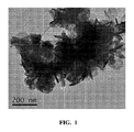
- C01P2004/04—Particle morphology depicted by an image obtained by TEM, STEM, STM or AFM
-
- C—CHEMISTRY; METALLURGY
- C01—INORGANIC CHEMISTRY
- C01P—INDEXING SCHEME RELATING TO STRUCTURAL AND PHYSICAL ASPECTS OF SOLID INORGANIC COMPOUNDS
- C01P2004/00—Particle morphology
- C01P2004/60—Particles characterised by their size
- C01P2004/62—Submicrometer sized, i.e. from 0.1-1 micrometer
-
- C—CHEMISTRY; METALLURGY
- C01—INORGANIC CHEMISTRY
- C01P—INDEXING SCHEME RELATING TO STRUCTURAL AND PHYSICAL ASPECTS OF SOLID INORGANIC COMPOUNDS
- C01P2004/00—Particle morphology
- C01P2004/60—Particles characterised by their size
- C01P2004/64—Nanometer sized, i.e. from 1-100 nanometer
-
- C—CHEMISTRY; METALLURGY
- C01—INORGANIC CHEMISTRY
- C01P—INDEXING SCHEME RELATING TO STRUCTURAL AND PHYSICAL ASPECTS OF SOLID INORGANIC COMPOUNDS
- C01P2006/00—Physical properties of inorganic compounds
- C01P2006/40—Electric properties
-
- Y—GENERAL TAGGING OF NEW TECHNOLOGICAL DEVELOPMENTS; GENERAL TAGGING OF CROSS-SECTIONAL TECHNOLOGIES SPANNING OVER SEVERAL SECTIONS OF THE IPC; TECHNICAL SUBJECTS COVERED BY FORMER USPC CROSS-REFERENCE ART COLLECTIONS [XRACs] AND DIGESTS
- Y02—TECHNOLOGIES OR APPLICATIONS FOR MITIGATION OR ADAPTATION AGAINST CLIMATE CHANGE
- Y02E—REDUCTION OF GREENHOUSE GAS [GHG] EMISSIONS, RELATED TO ENERGY GENERATION, TRANSMISSION OR DISTRIBUTION
- Y02E10/00—Energy generation through renewable energy sources
- Y02E10/50—Photovoltaic [PV] energy
- Y02E10/541—CuInSe2 material PV cells
-
- Y—GENERAL TAGGING OF NEW TECHNOLOGICAL DEVELOPMENTS; GENERAL TAGGING OF CROSS-SECTIONAL TECHNOLOGIES SPANNING OVER SEVERAL SECTIONS OF THE IPC; TECHNICAL SUBJECTS COVERED BY FORMER USPC CROSS-REFERENCE ART COLLECTIONS [XRACs] AND DIGESTS
- Y10—TECHNICAL SUBJECTS COVERED BY FORMER USPC
- Y10T—TECHNICAL SUBJECTS COVERED BY FORMER US CLASSIFICATION
- Y10T428/00—Stock material or miscellaneous articles
- Y10T428/23907—Pile or nap type surface or component
- Y10T428/23986—With coating, impregnation, or bond
-
- Y—GENERAL TAGGING OF NEW TECHNOLOGICAL DEVELOPMENTS; GENERAL TAGGING OF CROSS-SECTIONAL TECHNOLOGIES SPANNING OVER SEVERAL SECTIONS OF THE IPC; TECHNICAL SUBJECTS COVERED BY FORMER USPC CROSS-REFERENCE ART COLLECTIONS [XRACs] AND DIGESTS
- Y10—TECHNICAL SUBJECTS COVERED BY FORMER USPC
- Y10T—TECHNICAL SUBJECTS COVERED BY FORMER US CLASSIFICATION
- Y10T428/00—Stock material or miscellaneous articles
- Y10T428/24—Structurally defined web or sheet [e.g., overall dimension, etc.]
- Y10T428/24479—Structurally defined web or sheet [e.g., overall dimension, etc.] including variation in thickness
- Y10T428/24612—Composite web or sheet
-
- Y—GENERAL TAGGING OF NEW TECHNOLOGICAL DEVELOPMENTS; GENERAL TAGGING OF CROSS-SECTIONAL TECHNOLOGIES SPANNING OVER SEVERAL SECTIONS OF THE IPC; TECHNICAL SUBJECTS COVERED BY FORMER USPC CROSS-REFERENCE ART COLLECTIONS [XRACs] AND DIGESTS
- Y10—TECHNICAL SUBJECTS COVERED BY FORMER USPC
- Y10T—TECHNICAL SUBJECTS COVERED BY FORMER US CLASSIFICATION
- Y10T428/00—Stock material or miscellaneous articles
- Y10T428/26—Web or sheet containing structurally defined element or component, the element or component having a specified physical dimension
- Y10T428/268—Monolayer with structurally defined element
Landscapes
- Chemical & Material Sciences (AREA)
- Engineering & Computer Science (AREA)
- Organic Chemistry (AREA)
- Inorganic Chemistry (AREA)
- General Physics & Mathematics (AREA)
- Condensed Matter Physics & Semiconductors (AREA)
- Physics & Mathematics (AREA)
- Computer Hardware Design (AREA)
- Microelectronics & Electronic Packaging (AREA)
- Power Engineering (AREA)
- Nanotechnology (AREA)
- Manufacturing & Machinery (AREA)
- Electromagnetism (AREA)
- Materials Engineering (AREA)
- Crystallography & Structural Chemistry (AREA)
- Life Sciences & Earth Sciences (AREA)
- Wood Science & Technology (AREA)
- Chemical Kinetics & Catalysis (AREA)
- General Chemical & Material Sciences (AREA)
- Composite Materials (AREA)
- Inks, Pencil-Leads, Or Crayons (AREA)
- Powder Metallurgy (AREA)
- Pigments, Carbon Blacks, Or Wood Stains (AREA)
- Paints Or Removers (AREA)
- Photovoltaic Devices (AREA)
Abstract
本発明は、銅亜鉛スズ硫化物/セレン化物および銅スズ硫化物/セレン化物の有用な前駆体である金属カルコゲニドナノ粒子の水性製造方法に関する。さらに、本発明は、金属カルコゲニドナノ粒子からの結晶性粒子の製造方法、ならびに金属カルコゲニドナノ粒子および結晶性粒子の両方からのインクの調製方法を提供する。The present invention relates to an aqueous process for producing metal chalcogenide nanoparticles that are useful precursors of copper zinc tin sulfide / selenide and copper tin sulfide / selenide. Furthermore, the present invention provides a method for producing crystalline particles from metal chalcogenide nanoparticles, and a method for preparing ink from both metal chalcogenide nanoparticles and crystalline particles.
Description
関連出願の相互参照
本出願は、それらのそれぞれが2009年11月25日に出願された、そしてそれらのそれぞれがあらゆる目的のために本明細書の一部として全体をこの参照により援用される、米国仮特許出願第61/264,383号明細書、同第61/264,387号明細書、同第61/264,389号明細書、同第61/264,393号明細書、および同第61/264,404号明細書の、米国特許法第119条(e)項の下での優先権、および利益を主張するものである。
CROSS REFERENCE TO RELATED APPLICATIONS This application was filed on November 25, 2009, each of which is incorporated herein by reference in its entirety for each purpose, US provisional patent applications 61 / 264,383, 61 / 264,387, 61 / 264,389, 61 / 264,393, and No. 61 / 264,404, which claims priority and benefit under 35 USC 119 (e).
本発明は、銅亜鉛スズ硫化物/セレン化物および銅スズ硫化物/セレン化物の有用な前駆体である金属カルコゲニドナノ粒子の水性製造方法に関する。さらに、本発明は、金属カルコゲニドナノ粒子からの結晶性粒子の製造方法、ならびに金属カルコゲニドナノ粒子および結晶性粒子の両方からのインクの調製方法を提供する。 The present invention relates to an aqueous process for producing metal chalcogenide nanoparticles that are useful precursors of copper zinc tin sulfide / selenide and copper tin sulfide / selenide. Furthermore, the present invention provides a method for producing crystalline particles from metal chalcogenide nanoparticles, and a method for preparing ink from both metal chalcogenide nanoparticles and crystalline particles.
粒子および層を含む、結晶性多元−金属カルコゲニド組成物は、半導体、導体、および熱電体としての使用を含む、触媒作用およびエレクトロニクスにおいて用途を有する、有用な材料である。 Crystalline multi-metal chalcogenide compositions, including particles and layers, are useful materials with applications in catalysis and electronics, including use as semiconductors, conductors, and thermoelectrics.
非毒性の、かつ、豊富な元素のみを含有する結晶性多元−金属カルコゲニド組成物は、環境上持続可能な方法およびデバイスを開発する上で特に興味深い。銅スズ硫化物(Cu2SnS3または「CTS」)および銅亜鉛スズ硫化物(Cu2ZnSnS4または「CZTS」)は、このクラスの材料の特に有用な例である。CTSは、小バンドギャップ半導体としての、非線形材料としての、および光起電力セル材料の好適な候補としてのそれらの潜在的な用途のために興味深い、一般式IB2−IVA−VIA3で表される、化合物の群に属する。 Crystalline multi-metal chalcogenide compositions that are non-toxic and contain only abundant elements are of particular interest in developing environmentally sustainable methods and devices. Copper tin sulfide (Cu 2 SnS 3 or “CTS”) and copper zinc tin sulfide (Cu 2 ZnSnS 4 or “CZTS”) are particularly useful examples of this class of materials. CTS is represented by the general formula IB 2 -IVA-VIA 3 , interesting for their potential use as small band gap semiconductors, as nonlinear materials, and as suitable candidates for photovoltaic cell materials. Belonging to the group of compounds.
薄膜光起電力セルは、CdTeまたは銅インジウムガリウム硫化物/セレン化物(CIGS)などの半導体をエネルギー吸収体材料として典型的には使用する。カドミウムの毒性およびインジウムの制限された入手可能性のために、代替品が求められている。CZTSは、約1.5eVのバンドギャップエネルギーおよび大きい吸収係数(約104cm-1)を有し、有望なCIGS代替品となっている。 Thin film photovoltaic cells typically use semiconductors such as CdTe or copper indium gallium sulfide / selenide (CIGS) as the energy absorber material. Alternatives are sought because of the toxicity of cadmium and the limited availability of indium. CZTS has a band gap energy of about 1.5 eV and a large absorption coefficient (about 10 4 cm −1 ), making it a promising CIGS replacement.
CZTS薄膜の製造における課題は、結晶性多元−金属カルコゲニド組成物のフィルムを製造する際に克服されなければならない一般的な課題を例示するものである。CZTS薄膜を製造するための現行技法(たとえば、熱蒸着、スパッタリング、ハイブリッドスパッタ法、パルスレーザー堆積および電子ビーム蒸着)は、複雑な設備を必要とし、それ故高くつく傾向がある。電気化学析出は費用のかからない方法であるが、組成の非一様性および/または二次相の存在により、この方法で高品質CZTS薄膜を生み出すのが妨げられる。CZTS薄膜はまた、チオウレアを硫黄源として使用して、金属塩、典型的にはCuCl、ZnCl2、およびSnCl4を含有する溶液の噴霧熱分解によって製造することができる。この方法は、不十分なモルフォロジ、密度および粒度のフィルムをもたらす傾向がある。光化学堆積はまた、p−型CZTS薄膜を生み出すことが示されている。しかし、生成物の組成が十分には制御されず、水酸化物などの不純物の形成を回避することが困難である。 The challenges in the production of CZTS thin films are illustrative of the general challenges that must be overcome in producing films of crystalline multi-metal chalcogenide compositions. Current techniques for producing CZTS thin films (eg, thermal evaporation, sputtering, hybrid sputtering, pulsed laser deposition and electron beam evaporation) require complex equipment and therefore tend to be expensive. Although electrochemical deposition is an inexpensive method, compositional non-uniformity and / or the presence of secondary phases prevent this method from producing high quality CZTS thin films. CZTS films also use thiourea as the sulfur source, metal salts, typically can be prepared CuCl, by spray pyrolysis of a solution containing ZnCl 2, and SnCl 4. This method tends to result in films with insufficient morphology, density and particle size. Photochemical deposition has also been shown to produce p-type CZTS thin films. However, the composition of the product is not well controlled and it is difficult to avoid the formation of impurities such as hydroxides.
有機アミンで安定化され、そして有機溶媒で処理されたCZTSナノ粒子の合成もまた開示されている。これらのナノ粒子の層は、標準コーティング技法によって基板上に堆積させられた。窒素および硫黄雰囲気中でのその後のアニーリングは、CZTSフィルムの形成につながる。しかし、CZTS薄膜の究極的な性能に影響を及ぼす、CZTS粉体中の元素のモル比を調整することは困難である。 The synthesis of CZTS nanoparticles stabilized with organic amines and treated with organic solvents is also disclosed. These nanoparticle layers were deposited on the substrate by standard coating techniques. Subsequent annealing in nitrogen and sulfur atmospheres leads to the formation of CZTS film. However, it is difficult to adjust the molar ratio of elements in the CZTS powder that affects the ultimate performance of the CZTS thin film.
調整可能な組成、サイズ、およびモルフォロジの、高品質の結晶性多元−金属カルコゲニド粒子およびフィルムを提供する方法が依然として必要とされている。水を溶媒として使用してこれらの粒子を製造することができる、低コストの環境にやさしい方法を開発することが望ましい。豊富なおよび非毒性の元素に基づくCTSおよびCZTSなどの組成物の粒子の形成方法が特に興味深い。 There remains a need for methods that provide high quality crystalline multi-metal chalcogenide particles and films of adjustable composition, size, and morphology. It is desirable to develop a low cost, environmentally friendly method that can produce these particles using water as a solvent. Of particular interest are methods of forming particles of compositions such as CTS and CZTS based on abundant and non-toxic elements.
本発明の一態様は、銅塩、スズ塩、任意選択的に亜鉛塩、1つ以上の配位子、およびカルコゲニド源を反応させて結晶性銅スズ硫化物/セレン化物または結晶性銅亜鉛スズ硫化物/セレン化物組成物の有用な前駆体である金属カルコゲニドナノ粒子を製造するための水性方法を提供する。 One aspect of the present invention is to react a copper salt, a tin salt, optionally a zinc salt, one or more ligands, and a chalcogenide source to produce crystalline copper tin sulfide / selenide or crystalline copper zinc tin. An aqueous method is provided for producing metal chalcogenide nanoparticles that are useful precursors of sulfide / selenide compositions.
本発明の別の態様は、金属カルコゲニドナノ粒子からの結晶性多元−金属カルコゲニド粒子の製造方法を提供する。これらの粒子は、高い百分率の結晶性銅スズ硫化物/セレン化物または結晶性銅亜鉛スズ硫化物/セレン化物画分を含む。 Another aspect of the present invention provides a method for producing crystalline multi-metal chalcogenide particles from metal chalcogenide nanoparticles. These particles contain a high percentage of crystalline copper tin sulphide / selenide or crystalline copper zinc tin sulphide / selenide fraction.
本明細書においては、用語「太陽電池」および「光起電力セル」は、そうでないと具体的に定義されない限り同意語である。これらの用語は、可視および近可視光エネルギーを使用に適した電気エネルギーに変換するための半導体を使用するデバイスを意味する。用語「バンドギャップエネルギー」、「光学バンドギャップ」、および「バンドギャップ」は、そうでないと具体的に定義されない限り同意語である。これらの用語は、一般に、電子を価電子帯から伝導帯に励起するために必要な最小エネルギーである、半導体材料中に電子−正孔ペアを生み出すために必要なエネルギーを意味する。 As used herein, the terms “solar cell” and “photovoltaic cell” are synonymous unless specifically defined otherwise. These terms refer to devices that use semiconductors to convert visible and near visible light energy into electrical energy suitable for use. The terms “bandgap energy”, “optical bandgap”, and “bandgap” are synonymous unless specifically defined otherwise. These terms generally mean the energy required to create an electron-hole pair in a semiconductor material, which is the minimum energy required to excite electrons from the valence band to the conduction band.
本明細書においては、元素族はCAS表記法を用いて表される。本明細書において使用される場合、用語「カルコゲン」は、族VIA元素を意味し、用語「金属カルコゲニド」または「カルコゲニド」は、金属と族VIA元素とを含む材料を意味する。好適な族VIA元素としては、硫黄、セレンおよびテルルが挙げられる。金属カルコゲニドは、これらの化合物の多くが十分に地球太陽スペクトル内の光学バンドギャップ値を有するので、光起電用途向けの重要な候補材料である。 In this specification, element groups are represented using CAS notation. As used herein, the term “chalcogen” refers to a Group VIA element, and the term “metal chalcogenide” or “chalcogenide” refers to a material that includes a metal and a Group VIA element. Suitable Group VIA elements include sulfur, selenium and tellurium. Metal chalcogenides are important candidate materials for photovoltaic applications because many of these compounds have optical band gap values well within the earth solar spectrum.
本明細書においては用語「二元金属カルコゲニド」は、1つの金属を含むカルコゲニド組成物を意味する。用語「三元金属カルコゲニド」は、2つの金属を含むカルコゲニド組成物を意味する。用語「四元金属カルコゲニド」は3つの金属を含むカルコゲニド組成物を意味する。用語「多元−金属カルコゲニド」は、2つ以上の金属を含む組成物を意味し、三元および四元金属カルコゲニド組成物を包含する。 As used herein, the term “bimetallic chalcogenide” refers to a chalcogenide composition comprising one metal. The term “ternary metal chalcogenide” refers to a chalcogenide composition comprising two metals. The term “quaternary metal chalcogenide” refers to a chalcogenide composition comprising three metals. The term “multi-metal chalcogenide” means a composition comprising two or more metals and includes ternary and quaternary metal chalcogenide compositions.
本明細書においては用語「単一式の結晶性多元−金属カルコゲニド」は、具体的な多元−金属組成物の硫黄、セレンおよびテルルのカルコゲニドのすべての可能な組み合わせを包含する。たとえば、式IB2−IVA−VIA3は、Cu2SnS3、および(Cu,Ag)2SnTe3を含む、(Cu,Ag,Au)2(C,Si,Ge,Sn,Pb)(S,Se,Te)3のすべての可能な組み合わせを包含する単一式の結晶性多元−金属カルコゲニドを表す。(Cu,Ag)2SnTe3は、Cu2SnTe3、Ag2SnTe3、および(CuxAg1-x)2SnTe3(ここで、0≦x≦1)を包含する。元素は、金属カルコゲニドナノ粒子前駆体混合物を製造するための反応混合物に使用される具体的な金属塩およびカルコゲン源によって決定されるであろう。(Cu,Ag,Au)1.80(C,Si,Ge,Sn,Pb)1.05(S,Se,Te)3などの端数の化学量論は、この用語によってさらに包含される。これらの材料はまた、少量のその他の元素を含有することができる。これは、銅スズ硫化物/セレン化物および銅亜鉛スズ硫化物/セレン化物について下により具体的に例示される。 As used herein, the term “single crystalline multi-metal chalcogenide” encompasses all possible combinations of the specific multi-metal composition sulfur, selenium and tellurium chalcogenides. For example, the formula IB 2 -IVA-VIA 3 includes (Cu, Ag, Au) 2 (C, Si, Ge, Sn, Pb) (S), including Cu 2 SnS 3 and (Cu, Ag) 2 SnTe 3. , Se, Te) represents a single-form crystalline multi-metal chalcogenide encompassing all possible combinations of 3 . (Cu, Ag) 2 SnTe 3 includes Cu 2 SnTe 3 , Ag 2 SnTe 3 , and (Cu x Ag 1-x ) 2 SnTe 3 (where 0 ≦ x ≦ 1). The element will be determined by the specific metal salt and chalcogen source used in the reaction mixture to produce the metal chalcogenide nanoparticle precursor mixture. Fractional stoichiometry such as (Cu, Ag, Au) 1.80 (C, Si, Ge, Sn, Pb) 1.05 (S, Se, Te) 3 is further encompassed by this term. These materials can also contain small amounts of other elements. This is illustrated more specifically below for copper tin sulfide / selenide and copper zinc tin sulfide / selenide.
本明細書においては、用語「銅スズ硫化物」および「CTS」はCu2SnS3を意味し;「銅スズセレン化物」および「CTSe」はCu2SnSe3を意味し;「銅スズ硫化物/セレン化物」および「CTS/Se」は、Cu2SnS3、Cu2SnSe3、およびCu2SnSxSe3-x(ここで、0≦x≦3)を含む、Cu2Sn(S,Se)3のすべての可能な組み合わせを包含する。これらの用語「銅スズ硫化物」、「銅スズセレン化物」、「銅スズ硫化物/セレン化物」、「CTS」、「CTSe」および「CTS/Se」は、端数の化学量論、たとえば、Cu1.80Sn1.05S3をさらに包含する。すなわち、元素の化学量論は、厳密に2:1:3モル比から異なることができる。 As used herein, the term "copper-tin sulfide" and "CTS" means Cu 2 SnS 3; "copper Suzuseren halide" and "CTSe" means Cu 2 SnSe 3; "copper-tin sulfide / selenides "and" CTS / Se "is, Cu 2 SnS 3, Cu 2 SnSe 3, and Cu 2 SnS x Se 3-x ( wherein, 0 ≦ x ≦ 3) including, Cu 2 Sn (S, Se Include all 3 possible combinations. These terms “copper tin sulfide”, “copper tin selenide”, “copper tin sulfide / selenide”, “CTS”, “CTSe” and “CTS / Se” are fractional stoichiometry, eg, Cu Further includes 1.80 Sn 1.05 S 3 . That is, the stoichiometry of the elements can vary strictly from a 2: 1: 3 molar ratio.
本明細書においては、用語銅亜鉛スズ硫化物および「CZTS」はCu2ZnSnS4を意味し、銅亜鉛スズセレン化物および「CZTSe」はCu2ZnSnSe4を意味し、銅亜鉛スズ硫化物/セレン化物および「CZTS/Se」は、Cu2ZnSnS4、Cu2ZnSnSe4、およびCu2ZnSnSxSe4-x(ここで、0≦x≦4)を含む、Cu2ZnSn(S,Se)4のすべての可能な組み合わせを包含する。用語「CZTS」、「CZTSe」、および「CZTS/Se」は、端数の化学量論の銅亜鉛スズ硫化物/セレン化物半導体、たとえば、Cu1.94Zn0.63Sn1.3S4をさらに包含する。すなわち、元素の化学量論は、厳密には2:1:1:4モル比から異なり得る。CTS/SeおよびCZTS/Seと表される材料はまた、ナトリウムなどの少量のその他の元素を含有してもよい。CZTSは、ケステライト構造で結晶化し、本明細書において使用される場合、用語「ケステライト」はこの結晶構造を意味する。 As used herein, the term copper zinc tin sulphide and "CZTS" means Cu 2 ZnSnS 4, copper-zinc Suzuseren halides and "CZTSe" means Cu 2 ZnSnSe 4, copper zinc tin sulphide / selenide and "CZTS-/ Se" is, Cu 2 ZnSnS 4, Cu 2 ZnSnSe 4, and Cu 2 ZnSnS x Se 4-x ( where, 0 ≦ x ≦ 4) including, Cu 2 ZnSn (S, Se ) 4 of Includes all possible combinations. The terms “CZTS”, “CZTSe”, and “CZTS / Se” further include fractional stoichiometric copper zinc tin sulfide / selenide semiconductors, eg, Cu 1.94 Zn 0.63 Sn 1.3 S 4 . That is, the stoichiometry of the elements can vary strictly from a 2: 1: 1: 4 molar ratio. Materials designated CTS / Se and CZTS / Se may also contain minor amounts of other elements such as sodium. CZTS crystallizes with a kesterite structure and, as used herein, the term “kesterite” means this crystal structure.
用語「ナノ粒子」は、約1nm〜約1000nm、または約5nm〜約500nm、または約10nm〜約100nm、または約1nm〜約200nm、または約1nm〜約100nm、または約1nm〜約50nm、または約1nm〜約25nmの平均最長寸法で特徴付けられるカルコゲニド含有粒子を含むことを意図される。ナノ粒子は、多面体、球体、棒、ワイヤー、チューブ、フレーク、ウィスカー、リング、ディスク、またはプリズムを含む、様々な形状を有することができる。そうでないと明記されない限り、ナノ粒子は、分散助剤としての機能を果たすことができる「表面コーティング」を有することができる。本明細書においては「キャッピング基」または「キャッピング剤」と言われてもよい、表面コーティングは、ナノ粒子に物理的に吸着され得るかまたはナノ粒子に化学的に結合することができる。この表面コーティングはまた溶媒であることができるか、または反応混合物に添加される1つ以上の配位子を含むことがきる。無機ナノ粒子の表面コーティング方法は、当該技術分野においてよく知られている。本明細書の全体にわたって、ナノ粒子の重量%についてのすべての言及は、この表面コーティングを含むことを意図される。 The term “nanoparticle” refers to about 1 nm to about 1000 nm, or about 5 nm to about 500 nm, or about 10 nm to about 100 nm, or about 1 nm to about 200 nm, or about 1 nm to about 100 nm, or about 1 nm to about 50 nm, or about It is intended to include chalcogenide-containing particles characterized by an average longest dimension of 1 nm to about 25 nm. Nanoparticles can have a variety of shapes including polyhedra, spheres, rods, wires, tubes, flakes, whiskers, rings, discs, or prisms. Unless otherwise specified, the nanoparticles can have a “surface coating” that can serve as a dispersion aid. A surface coating, which may be referred to herein as a “capping group” or “capping agent”, can be physically adsorbed to or chemically bonded to the nanoparticle. This surface coating can also be a solvent or can include one or more ligands added to the reaction mixture. Inorganic nanoparticle surface coating methods are well known in the art. Throughout this specification, all references to weight percent of nanoparticles are intended to include this surface coating.
本明細書において用語「インク」、「ペースト」、および「分散系」は、そうでないと具体的に定義されない限り、同義語である。 As used herein, the terms “ink”, “paste”, and “dispersion” are synonymous unless specifically defined otherwise.
金属カルコゲニドナノ粒子前駆体混合物
結晶性多元−金属カルコゲニド組成物の製造方法が本明細書に記載される。本方法は、一般に入手可能な前駆体を使用し、適度の温度および拡張可能な濃度で動作し、化学量論の調整を可能にする。
Metal Chalcogenide Nanoparticle Precursor Mixture A method for making a crystalline multi-metal chalcogenide composition is described herein. The method uses commonly available precursors, operates at moderate temperatures and expandable concentrations, and allows for stoichiometric adjustment.
本発明の一態様は、
(a)2つ以上の金属塩および1つ以上の配位子を含む第1水性溶液を提供する工程と;
(b)任意選択的に、pH調整物質を添加して第2水性溶液を形成する工程と;
(c)第1または第2水性溶液をカルコゲン源と組み合わせて反応混合物を提供する工程と;
(d)反応混合物を撹拌しておよび任意選択的に加熱して金属カルコゲニドナノ粒子を生成する工程と
を含む方法である。
One embodiment of the present invention provides:
(A) providing a first aqueous solution comprising two or more metal salts and one or more ligands;
(B) optionally adding a pH adjusting material to form a second aqueous solution;
(C) combining the first or second aqueous solution with a chalcogen source to provide a reaction mixture;
(D) stirring the reaction mixture and optionally heating to produce metal chalcogenide nanoparticles.
一実施形態においては、本方法は、金属カルコゲニドナノ粒子を反応混合物から分離する工程をさらに含む。別の実施形態においては、本方法は、ナノ粒子の表面を清浄にする工程をさらに含む。別の実施形態においては、本方法は、ナノ粒子の表面をキャッピング基と反応させる工程をさらに含む。 In one embodiment, the method further comprises separating the metal chalcogenide nanoparticles from the reaction mixture. In another embodiment, the method further comprises the step of cleaning the surface of the nanoparticles. In another embodiment, the method further comprises reacting the surface of the nanoparticle with a capping group.
金属塩。好適な金属塩は、族VIII、IB、IIB、IIIA、IVA、およびVA元素からなる群から選択される金属を含む。特に、好適な金属塩は、Cu、Ag、Zn、Cd、Al、Ga、In、Si、Ge、およびSnからなる群から選択される金属を含む。所望の結晶性多元−金属カルコゲニド組成物における金属のモル比は、金属塩のモル比を決定するための手引きを提供する。しかし、反応剤化学量論のある範囲は同じ結晶性多元−金属カルコゲニド組成物の生成につながり得るので、反応剤の化学量論には典型的には柔軟性がある。たとえば、結晶性IB2−IIB−IVA−VIA4およびIB2−IVA−VIA3組成物の前駆体であるナノ粒子混合物の合成において、有用なモル比としては、約0.4〜約5、または約1〜約3、または約1.5〜約2.75の金属IB対金属IVAが挙げられる。金属IIBが存在する場合、金属IB対金属IIBのモル比は、約0.4〜約5、または約1〜約3、およびまたは約1.5〜約2.75であり;金属IIB対金属IVAのモル比は、約0.3〜約5、または約0.5〜約3、または約0.75〜約2である。 Metal salt. Suitable metal salts include metals selected from the group consisting of elements of Groups VIII, IB, IIB, IIIA, IVA, and VA. In particular, suitable metal salts include metals selected from the group consisting of Cu, Ag, Zn, Cd, Al, Ga, In, Si, Ge, and Sn. The molar ratio of metals in the desired crystalline multi-metal chalcogenide composition provides guidance for determining the molar ratio of metal salts. However, the reactant stoichiometry is typically flexible because a range of reactant stoichiometry can lead to the production of the same crystalline multi-metal chalcogenide composition. For example, in the synthesis of nanoparticle mixtures that are precursors of crystalline IB 2 -IIB-IVA-VIA 4 and IB 2 -IVA-VIA 3 compositions, useful molar ratios are about 0.4 to about 5, Or about 1 to about 3, or about 1.5 to about 2.75 metal IB to metal IVA. When metal IIB is present, the molar ratio of metal IB to metal IIB is about 0.4 to about 5, or about 1 to about 3, and / or about 1.5 to about 2.75; metal IIB to metal The molar ratio of IVA is from about 0.3 to about 5, or from about 0.5 to about 3, or from about 0.75 to about 2.
好適な金属塩は、水および/または酸に可溶である。広範囲の金属塩に関する溶解性情報は、CRC Handbook of Chemistry and Physics,90th Edition;Lide,David R.,Ed;CRC Press:Florida,2009−2010;Chapter 4;43−101ページにおいて利用可能である。これらの金属塩の対イオンは、金属にイオン結合または共有結合することができる。たとえば、有用な対イオンとしては、ハライド、スルフェート、ナイトレート、アセテート、アセチルアセトネート、パークロレート、ハイポクロライト、シアニド、ヒドロキシド、オキサレート、およびホスフェート対イオンが挙げられる。 Suitable metal salts are soluble in water and / or acid. Solubility information on a wide range of metal salts, CRC Handbook of Chemistry and Physics, 90 th Edition; Lide, David R. CRC Press: Florida, 2009-2010; Chapter 4; available on pages 43-101. The counter ions of these metal salts can be ionic or covalently bound to the metal. For example, useful counterions include halide, sulfate, nitrate, acetate, acetylacetonate, perchlorate, hypochlorite, cyanide, hydroxide, oxalate, and phosphate counterions.
配位子。理論に制約されることなく、反応混合物中に存在する1つ以上の配位子は、金属塩と錯体を形成するのに役割を果たし、そしてまた生じた金属カルコゲニドナノ粒子のための分散剤またはキャッピング基としての機能を果たす可能性があると考えられる。好適な配位子としては、アミン、チオール、セレノール、有機酸、およびそれらのイオンが挙げられる。特に、好適な配位子としては、アンモニア、メルカプト酢酸、エタノールアミン(EA)、ジエタノールアミン(DEA)、トリエタノールアミン(TEA)、トリメタノールアミン(TMA)、ヘキサメチレンテトラミン(HMT)、エチレンジアミン(ED)、エチレンジアミン四酢酸(EDTA)、ニトリロトリアセテート、およびクエン酸ナトリウムが挙げられる。アンモニアの有用な源としては、アンモニウム塩、たとえば、硝酸アンモニウムが挙げられる。アンモニア(またはアンモニウム塩)は、メルカプト酢酸、エタノールアミン(EA)、ジエタノールアミン(DEA)、トリエタノールアミン(TEA)、トリメタノールアミン(TMA)、ヘキサメチレンテトラミン(HMT)、エチレンジアミン(ED)、エチレンジアミン四酢酸(EDTA)、ニトリロトリアセテート、およびクエン酸ナトリウムなどの、1つ以上の追加の配位子と組み合わせて使用することができる。 Ligand. Without being bound by theory, the one or more ligands present in the reaction mixture serve to form a complex with the metal salt, and also a dispersing agent for the resulting metal chalcogenide nanoparticles or It may be possible to serve as a capping group. Suitable ligands include amines, thiols, selenols, organic acids, and their ions. Particularly suitable ligands include ammonia, mercaptoacetic acid, ethanolamine (EA), diethanolamine (DEA), triethanolamine (TEA), trimethanolamine (TMA), hexamethylenetetramine (HMT), ethylenediamine (ED ), Ethylenediaminetetraacetic acid (EDTA), nitrilotriacetate, and sodium citrate. Useful sources of ammonia include ammonium salts such as ammonium nitrate. Ammonia (or ammonium salt) is mercaptoacetic acid, ethanolamine (EA), diethanolamine (DEA), triethanolamine (TEA), trimethanolamine (TMA), hexamethylenetetramine (HMT), ethylenediamine (ED), ethylenediamine It can be used in combination with one or more additional ligands such as acetic acid (EDTA), nitrilotriacetate, and sodium citrate.
pH調整物質。pH調整物質を、pHを約4〜約0に;または約2〜約0に調整するために反応混合物に任意選択的に添加することができる。有用なpH調整物質は酸および塩基である。好適なpH調整物質としては、プロトン酸、たとえば、硫酸、硝酸および塩酸が挙げられる。あるいは、pH調整物質を、pHを約10〜約14に;または約12〜約14に調整するために使用することができる。この方式のために、好適なpH調整物質としては、塩基が挙げられる。 pH adjusting substance. A pH adjusting material can optionally be added to the reaction mixture to adjust the pH to about 4 to about 0; or about 2 to about 0. Useful pH adjusting substances are acids and bases. Suitable pH adjusting substances include protic acids such as sulfuric acid, nitric acid and hydrochloric acid. Alternatively, a pH adjusting material can be used to adjust the pH to about 10 to about 14; or about 12 to about 14. For this scheme, suitable pH adjusting substances include bases.
カルコゲン源。理論に制約されることなく、本合成に使用されるカルコゲンまたはカルコゲニド源は反応混合物中で硫化物またはセレン化物イオンをゆっくり発生させると考えられる。好適なカルコゲン源としては、硫化物−およびチオン−含有化合物ならびにそれらのセレン化物およびセレノン相当品が挙げられる。チオン−およびセレノン−含有化合物は、塩基性または酸性条件下にカルコゲニドを放出する能力を有する。特に、好適なカルコゲン源としては、アルカリ金属の硫化物およびセレン化物、ならびにチオン−およびセレノン−含有化合物、たとえば、硫化ナトリウム、セレン化ナトリウム、チオアセトアミド、セレノアセトアミド、チオ尿素およびセレノ尿素が挙げられる。カルコゲン源対金属塩の総モル数のモル比は、少なくとも約1;または少なくとも約2;または少なくとも約4;または少なくとも約8である。 Chalcogen source. Without being bound by theory, it is believed that the chalcogen or chalcogenide source used in this synthesis will slowly generate sulfide or selenide ions in the reaction mixture. Suitable chalcogen sources include sulfide- and thione-containing compounds and their selenides and selenone equivalents. Thion- and selenone-containing compounds have the ability to release chalcogenides under basic or acidic conditions. In particular, suitable chalcogen sources include alkali metal sulfides and selenides, and thione- and selenone-containing compounds such as sodium sulfide, sodium selenide, thioacetamide, selenoacetamide, thiourea and selenourea. . The molar ratio of the total number of moles of chalcogen source to metal salt is at least about 1; or at least about 2; or at least about 4; or at least about 8.
濃度。金属カルコゲニドナノ粒子を製造するための本明細書に記載される製造は、比較的高い濃度で行うことができる。反応混合物中の総合金属塩の有用な濃度は、約0.01超;または約0.02超;または約0.03超;または約0.04超;または約0.05モル濃度超である。 concentration. The production described herein for producing metal chalcogenide nanoparticles can be performed at relatively high concentrations. Useful concentrations of the total metal salt in the reaction mixture are greater than about 0.01; or greater than about 0.02; or greater than about 0.03; or greater than about 0.04; or greater than about 0.05 molar. .
撹拌および加熱。反応混合物を撹拌するおよび任意選択的に加熱すると、金属カルコゲニドナノ粒子を与える。好適な加熱温度は、約40℃〜約100℃、または約50℃〜約100℃;または約60〜約90℃;または約65〜約85℃である。撹拌は、かき混ぜ、超音波処理、および振盪を含む、標準方法によって達成することができる。有用な加熱時間は、約10分から約48時間まで;または約24時間まで;または約12時間まで;または約8時間まで;または約4時間までである。 Stir and heat. Stirring and optionally heating the reaction mixture gives metal chalcogenide nanoparticles. Suitable heating temperatures are from about 40 ° C to about 100 ° C, or from about 50 ° C to about 100 ° C; or from about 60 to about 90 ° C; or from about 65 to about 85 ° C. Agitation can be achieved by standard methods including agitation, sonication, and shaking. Useful heating times are from about 10 minutes to about 48 hours; or up to about 24 hours; or up to about 12 hours; or up to about 8 hours; or up to about 4 hours.
副生物からの分離。生じた金属カルコゲニドナノ粒子は、単離金属カルコゲニドナノ粒子を与えるために反応副生物から分離することができる。この分離は、遠心分離、洗浄、溶媒分離、濾過、およびそれらの組み合わせを含む、標準方法によって達成することができる。分離の有用な方法は、遠心分離、引き続く洗浄である。粒子は、任意選択的に乾燥させることができる。乾燥のための有用な温度範囲は、約20℃〜約200℃である。乾燥プロセスのための好適な雰囲気としては、不活性雰囲気、空気、または真空が挙げられる。 Separation from by-products. The resulting metal chalcogenide nanoparticles can be separated from the reaction byproducts to provide isolated metal chalcogenide nanoparticles. This separation can be accomplished by standard methods including centrifugation, washing, solvent separation, filtration, and combinations thereof. A useful method of separation is centrifugation followed by washing. The particles can optionally be dried. A useful temperature range for drying is from about 20 ° C to about 200 ° C. Suitable atmospheres for the drying process include an inert atmosphere, air, or vacuum.
ナノ粒子キャラクタリゼーションおよび組成物。金属カルコゲニドナノ粒子は、約1nm〜約1000nm、または約5nm〜約500nm、または約10nm〜約100nm、または約1nm〜約200nm、または約1nm〜約100nm、または約1nm〜約50nm、または約1nm〜約25nmの平均最長寸法で特徴付けられる。金属カルコゲニドナノ粒子は、各金属の二元金属カルコゲニドおよび各金属の多元−金属カルコゲニドからなる群から選択される2つ以上の組成物を含む。たとえば、金属1および金属2として本明細書において表される、2つの金属を含む反応混合物については、生じた金属カルコゲニドナノ粒子は、金属1カルコゲニド、金属2カルコゲニド、および金属1金属2カルコゲニドからなる群から選択される2つ以上の組成物を含むことができる。金属1、金属2および金属3として本明細書において表される、3つの金属を含む反応混合物については、生じた金属カルコゲニドナノ粒子は、金属1カルコゲニド、金属2カルコゲニド、金属3カルコゲニド、金属1金属2カルコゲニド、金属1金属3カルコゲニド、金属2金属3カルコゲニド、および金属1金属2金属3カルコゲニドからなる群から選択される2つ以上の組成物を含むことができる。類似の説明は、より高次の多元−金属カルコゲニド組成物の金属カルコゲニドナノ粒子前駆体に対しても適用される。金属は、2つ以上の酸化状態で存在することができる。また、硫化物とセレン化物との組み合わせなどの、2つ以上のカルコゲニドも存在することができる。 Nanoparticle characterization and composition. The metal chalcogenide nanoparticles can be about 1 nm to about 1000 nm, or about 5 nm to about 500 nm, or about 10 nm to about 100 nm, or about 1 nm to about 200 nm, or about 1 nm to about 100 nm, or about 1 nm to about 50 nm, or about 1 nm. Characterized by an average longest dimension of ˜about 25 nm. The metal chalcogenide nanoparticles comprise two or more compositions selected from the group consisting of a bimetallic chalcogenide of each metal and a multi-metal chalcogenide of each metal. For example, for a reaction mixture comprising two metals, represented herein as metal 1 and metal 2, the resulting metal chalcogenide nanoparticles consist of metal 1 chalcogenide, metal 2 chalcogenide, and metal 1 metal 2 chalcogenide. Two or more compositions selected from the group can be included. For reaction mixtures comprising three metals, represented herein as metal 1, metal 2 and metal 3, the resulting metal chalcogenide nanoparticles are metal 1 chalcogenide, metal 2 chalcogenide, metal 3 chalcogenide, metal 1 metal. Two or more compositions selected from the group consisting of 2 chalcogenides, metal 1 metal 3 chalcogenides, metal 2 metal 3 chalcogenides, and metal 1 metal 2 metal 3 chalcogenides can be included. Similar explanations apply to metal chalcogenide nanoparticle precursors of higher order multi-metal chalcogenide compositions. The metal can exist in more than one oxidation state. There can also be more than one chalcogenide, such as a combination of sulfides and selenides.
結晶性多元−金属カルコゲニド粒子
本発明の別の態様は、
(a)2つ以上の金属塩および1つ以上の配位子を含む第1水性溶液を提供する工程と;
(b)任意選択的に、pH調整物質を添加して第2水性溶液を形成する工程と;
(c)第1または第2水性溶液をカルコゲン源と組み合わせて反応混合物を提供する工程と;
(d)反応混合物を撹拌しておよび任意選択的に加熱して金属カルコゲニドナノ粒子を生成する工程と;
(e)金属カルコゲニドナノ粒子を反応副生物から分離する工程と;
(f)金属カルコゲニドナノ粒子を加熱して、粒子の重量を基準として、約80重量%〜100重量%の単一式の結晶性多元−金属カルコゲニド画分を含む結晶性多元−金属カルコゲニド粒子を提供する工程と
を含む方法である。
Crystalline multi-metal chalcogenide particles Another aspect of the present invention is:
(A) providing a first aqueous solution comprising two or more metal salts and one or more ligands;
(B) optionally adding a pH adjusting material to form a second aqueous solution;
(C) combining the first or second aqueous solution with a chalcogen source to provide a reaction mixture;
(D) stirring the reaction mixture and optionally heating to produce metal chalcogenide nanoparticles;
(E) separating metal chalcogenide nanoparticles from reaction byproducts;
(F) heating the metal chalcogenide nanoparticles to provide crystalline multi-metal chalcogenide particles comprising about 80 wt% to 100 wt% of a single crystalline multi-metal chalcogenide fraction based on the weight of the particles Including the step of:
本発明の別の態様は、粒子の重量を基準として、約80重量%〜100重量%の単一式の結晶性多元−金属カルコゲニド画分を含む結晶性多元−金属カルコゲニド粒子であって、
(a)2つ以上の金属塩および1つ以上の配位子を含む第1水性溶液を提供する工程と;
(b)任意選択的に、pH調整物質を添加して第2水性溶液を形成する工程と;
(c)第1または第2水性溶液をカルコゲン源と組み合わせて反応混合物を提供する工程と;
(d)反応混合物を撹拌しておよび任意選択的に加熱して金属カルコゲニドナノ粒子を生成する工程と;
(e)金属カルコゲニドナノ粒子を反応副生物から分離する工程と;
(f)金属カルコゲニドナノ粒子を加熱して結晶性多元−金属カルコゲニド粒子を提供する工程と
を含む方法によって製造される結晶性多元−金属粒子に関する。
Another aspect of the present invention is a crystalline multi-metal chalcogenide particle comprising from about 80% to 100% by weight of a single crystalline multi-metal chalcogenide fraction, based on the weight of the particle,
(A) providing a first aqueous solution comprising two or more metal salts and one or more ligands;
(B) optionally adding a pH adjusting material to form a second aqueous solution;
(C) combining the first or second aqueous solution with a chalcogen source to provide a reaction mixture;
(D) stirring the reaction mixture and optionally heating to produce metal chalcogenide nanoparticles;
(E) separating metal chalcogenide nanoparticles from reaction byproducts;
And (f) heating the metal chalcogenide nanoparticles to provide crystalline multi-metal chalcogenide particles.
工程(a)〜(e)ならびに組成物およびそれらの成分に関する説明および好ましさは、上にリストされたのと同じものである。 The explanations and preferences for steps (a)-(e) and the compositions and their components are the same as listed above.
一実施形態は、金属カルコゲニドナノ粒子の表面を清浄にする工程をさらに含む。別の実施形態は、金属カルコゲニドナノ粒子の表面をキャッピング基と反応させる工程をさらに含む。さらに別の実施形態は、結晶性多元−金属カルコゲニド粒子の表面を清浄にする工程を含む。別の実施形態は、結晶性多元−金属カルコゲニド粒子の表面をキャッピング基と反応させる工程を含む。 One embodiment further includes cleaning the surface of the metal chalcogenide nanoparticles. Another embodiment further comprises reacting the surface of the metal chalcogenide nanoparticles with a capping group. Yet another embodiment includes cleaning the surface of the crystalline multi-metal chalcogenide particles. Another embodiment includes reacting the surface of the crystalline multi-metal chalcogenide particles with a capping group.
加熱。工程(f)において、金属カルコゲニドナノ粒子は、粒子の重量を基準として、約80重量%〜100重量%の単一式の結晶性多元−金属カルコゲニド画分を含む結晶性多元−金属カルコゲニド粒子を与えるために約300℃〜約800℃、または約350℃〜約650℃、または約375℃〜約525℃の温度に典型的には加熱される。この加熱工程は、粒子中に存在するあらゆる水および/または有機種の実質的にすべてを除去するために役立つ。この加熱工程はまた、金属カルコゲニドナノ粒子の固体状態反応による単一式の結晶性多元−金属カルコゲニド画分の形成を容易にする。 heating. In step (f), the metal chalcogenide nanoparticles provide crystalline multi-metal chalcogenide particles comprising about 80% to 100% by weight of a single crystalline multi-metal chalcogenide fraction based on the weight of the particles. Typically about 300 ° C to about 800 ° C, or about 350 ° C to about 650 ° C, or about 375 ° C to about 525 ° C. This heating step serves to remove substantially all of the water and / or organic species present in the particles. This heating step also facilitates the formation of a single crystalline multi-metal chalcogenide fraction by solid state reaction of metal chalcogenide nanoparticles.
工程(f)の加熱は、熱処理を含む当該技術分野において公知の標準方法によって達成することができる。加熱は、不活性雰囲気、たとえば、N2またはArガスの雰囲気中で実施されてもよい。あるいは、この雰囲気は、ガルコゲン源をさらに含むことができる。一実施形態においては、フィルムは、硫黄に富む環境、たとえば、硫黄/N2環境中で加熱される。たとえば、加熱がチューブ炉で実施される場合、硫黄に富む雰囲気を作り出すために、窒素を、硫黄上方を流れるキャリアガスとして使用することができる。一実施形態においては、フィルムは、セレンに富む環境、たとえば、Se/N2環境中で加熱される。たとえば、加熱がチューブ炉で実施される場合、セレンに富む雰囲気を作り出すために、窒素を、セレン上方を流れるキャリアガスとして使用することができる。別の実施形態においては、フィルムは、硫化水素に富む雰囲気中で加熱される。たとえば、H2Sおよび窒素は、H2Sに富む雰囲気を作り出すために1:9の容積比で混合される。 Heating in step (f) can be accomplished by standard methods known in the art including heat treatment. Heating may be performed in an inert atmosphere, such as an atmosphere of N 2 or Ar gas. Alternatively, the atmosphere can further include a galcogen source. In one embodiment, the film is heated in a sulfur rich environment, eg, a sulfur / N 2 environment. For example, if heating is performed in a tube furnace, nitrogen can be used as a carrier gas flowing over sulfur to create a sulfur rich atmosphere. In one embodiment, the film is heated in a selenium rich environment, eg, a Se / N 2 environment. For example, if heating is performed in a tube furnace, nitrogen can be used as a carrier gas flowing over selenium to create a selenium rich atmosphere. In another embodiment, the film is heated in an atmosphere rich in hydrogen sulfide. For example, H 2 S and nitrogen are mixed in a volume ratio of 1: 9 to create an H 2 S rich atmosphere.
組成物。結晶性多元−金属カルコゲニド粒子の純度は、それらが単一式の結晶性多元−金属カルコゲニド画分から大部分はなるので高い。存在する場合、不純物は、幾らかの非晶質組成物および少量のその他の結晶性画分を含む。たとえば、TEMによって、幾つかの粒子は、表面上に非晶質カーボンの非常に薄い層がある結晶性画分から本質的になることが観察された。様々な実施形態においては、結晶性多元−金属カルコゲニド粒子は、粒子の重量を基準として、約80重量%〜100重量%;または約85重量%〜100重量%;または約90重量%〜100重量%;または約95重量%〜100重量%;または約98重量%〜100重量%;または約99重量%〜100重量%の、単一式の結晶性多元−金属カルコゲニド画分を含む。幾つかの実施形態においては、結晶性多元−金属カルコゲニド粒子は、単一式の結晶性多元−金属カルコゲニド画分から本質的になる。 Composition. The purity of the crystalline multi-metal chalcogenide particles is high because they consist mostly of a single crystalline multi-metal chalcogenide fraction. When present, impurities include some amorphous composition and small amounts of other crystalline fractions. For example, by TEM, it was observed that some particles consist essentially of a crystalline fraction with a very thin layer of amorphous carbon on the surface. In various embodiments, the crystalline multi-metal chalcogenide particles are about 80% to 100% by weight, or about 85% to 100% by weight, or about 90% to 100% by weight, based on the weight of the particles. Or about 95% to 100% by weight; or about 98% to 100% by weight; or about 99% to 100% by weight of a single crystalline multi-metal chalcogenide fraction. In some embodiments, the crystalline multi-metal chalcogenide particles consist essentially of a single set of crystalline multi-metal chalcogenide fractions.
様々な実施形態においては、単一式の結晶性多元−金属カルコゲニド画分は、族VIII、IB、IIB、IIIA、IVA、およびVA元素からなる群から選択される金属を含む。特に、好適な金属塩は、Cu、Ag、Zn、Cd、Al、Ga、In、Si、Ge、およびSnからなる群から選択される金属を含む。 In various embodiments, the single-form crystalline multi-metal chalcogenide fraction comprises a metal selected from the group consisting of group VIII, IB, IIB, IIIA, IVA, and VA elements. In particular, suitable metal salts include metals selected from the group consisting of Cu, Ag, Zn, Cd, Al, Ga, In, Si, Ge, and Sn.
結晶性多元−金属カルコゲニド粒子は、電気的に、磁気的に、触媒的におよび/または光学的に機能性の粒子を含む。粒子は、半導性;抵抗性;誘電性;導電性;発光性;電子生成性;正孔生成性;強誘電性;熱電性、圧電性;フェライト性;電気−光学性;磁性;光吸収性、光反射性、光回折性、光散乱性、光分散性、光屈折性、または光拡散性であっても;および/または屈折率を修正できるものであってもよい。触媒活性、熱電気特性、半導体特性および導電特性が特に興味深い。特に興味深い単一式の結晶性多元−金属カルコゲニドとしては、結晶性IB−IIIA−VIA、IB−IIB−IVA−VIAおよびIB−IVA−VIA組成物、ならびに結晶性IB−IIIA−VIA2、IB2−IIB−IVA−VIA4およびIB2−IVA−VIA3組成物からなる群から選択されるものが挙げられる。 Crystalline multi-metal chalcogenide particles include electrically, magnetically, catalytically and / or optically functional particles. Particles are semiconducting; resistive; dielectric; conductive; luminescent; electron generating; hole generating; ferroelectric; thermoelectric, piezoelectric; ferrite; electro-optical; May be reflective, light reflective, light diffractive, light scattering, light dispersive, photorefractive, or light diffusive; and / or capable of modifying the refractive index. Of particular interest are catalytic activity, thermoelectric properties, semiconductor properties and conductive properties. Particularly interesting single-form crystalline multi-metal chalcogenides include crystalline IB-IIIA-VIA, IB-IIB-IVA-VIA and IB-IVA-VIA compositions, and crystalline IB-IIIA-VIA 2 , IB 2 those selected from -IIB-IVA-VIA 4 and IB 2 -IVA-VIA 3 group consisting of compositions.
キャラクタリゼーション。結晶性多元−金属カルコゲニド粒子は、約1nm〜約10ミクロン;または約1nm〜約2000nm;または約1nm〜約1000nm;または約1nm〜約500nm;または約5nm〜約400nm;または約5nm〜約200nmの平均最長寸法で特徴付けられる。この平均最長寸法は多くの場合、金属カルコゲニドナノ粒子が工程(f)において加熱される時間に依存する。典型的には、より長い加熱時間は、より大きい平均最長寸法をもたらす。結晶性多元−金属カルコゲニド粒子は、形状およびアスペクト比でさらに特徴付けられる。これらの粒子は多くの場合、約4未満;または約3未満;または約2未満のアスペクト比の多面体形状で特徴付けられる。幾つかの実施形態においては、結晶性多元−金属カルコゲニド粒子は、約1nm〜約2000nm;または約1nm〜約1000nm;または約1nm〜約500nm;または約5nm〜約400nm;または約5nm〜約200nmのサイズ分布でさらに特徴付けられる。 characterization. Crystalline multi-metal chalcogenide particles can be about 1 nm to about 10 microns; or about 1 nm to about 2000 nm; or about 1 nm to about 1000 nm; or about 1 nm to about 500 nm; or about 5 nm to about 400 nm; or about 5 nm to about 200 nm. Characterized by an average longest dimension of This average longest dimension often depends on the time that the metal chalcogenide nanoparticles are heated in step (f). Typically, longer heating times result in a larger average longest dimension. Crystalline multi-metal chalcogenide particles are further characterized by shape and aspect ratio. These particles are often characterized by a polyhedral shape with an aspect ratio of less than about 4; or less than about 3; or less than about 2. In some embodiments, the crystalline multi-metal chalcogenide particles are about 1 nm to about 2000 nm; or about 1 nm to about 1000 nm; or about 1 nm to about 500 nm; or about 5 nm to about 400 nm; or about 5 nm to about 200 nm. Further characterized by the size distribution of
別の実施形態は、結晶性多元−金属カルコゲニド粒子を流体媒体と組み合わせてインクを提供する工程をさらに含む。 Another embodiment further comprises combining the crystalline multi-metal chalcogenide particles with a fluid medium to provide an ink.
金属カルコゲニドナノ粒子のおよび多元−金属粒子のインク
本発明の別の態様は、
(1)粒子の重量を基準として、約80重量%〜100重量%の単一式の結晶性多元−金属カルコゲニド画分を含む約2重量%〜約80重量%の結晶性多元−金属カルコゲニド粒子であって、
(a)2つ以上の金属塩および1つ以上の配位子を含む第1水性溶液を提供する工程と;
(b)任意選択的に、pH調整物質を添加して第2水性溶液を形成する工程と;
(c)第1または第2水性溶液をカルコゲン源と組み合わせて反応混合物を提供する工程と;
(d)反応混合物を撹拌しておよび任意選択的に加熱して金属カルコゲニドナノ粒子を生成する工程と;
(e)金属カルコゲニドナノ粒子を反応副生物から分離する工程と;
(f)金属カルコゲニドナノ粒子を加熱して結晶性多元−金属カルコゲニド粒子を提供する工程と
を含む方法によって製造される結晶性粒子
を含み、そして
(2)約20〜約98重量%の流体媒体
を含むインクに関する。
Metal Chalcogenide Nanoparticle and Multi-Metal Particle Inks Another aspect of the present invention is
(1) about 2% to about 80% by weight of crystalline multi-metal chalcogenide particles comprising about 80% to 100% by weight of a single crystalline multi-metal chalcogenide fraction, based on the weight of the particles There,
(A) providing a first aqueous solution comprising two or more metal salts and one or more ligands;
(B) optionally adding a pH adjusting material to form a second aqueous solution;
(C) combining the first or second aqueous solution with a chalcogen source to provide a reaction mixture;
(D) stirring the reaction mixture and optionally heating to produce metal chalcogenide nanoparticles;
(E) separating metal chalcogenide nanoparticles from reaction byproducts;
(F) heating the metal chalcogenide nanoparticles to provide crystalline multi-metal chalcogenide particles, and (2) from about 20 to about 98% by weight fluid medium The present invention relates to an ink containing.
工程(a)〜(f)ならびに組成およびそれらの成分に関する説明は、上にリストされたのと同じものである。 The explanations for steps (a) to (f) and the composition and their components are the same as listed above.
一実施形態は、金属カルコゲニドナノ粒子の表面を清浄にする工程をさらに含む。別の実施形態は、金属カルコゲニドナノ粒子の表面をキャッピング基と反応させる工程をさらに含む。さらに別の実施形態は、結晶性多元−金属カルコゲニド粒子の表面を清浄にする工程を含む。別の実施形態は、結晶性多元−金属カルコゲニド粒子の表面をキャッピング基と反応させる工程を含む。 One embodiment further includes cleaning the surface of the metal chalcogenide nanoparticles. Another embodiment further comprises reacting the surface of the metal chalcogenide nanoparticles with a capping group. Yet another embodiment includes cleaning the surface of the crystalline multi-metal chalcogenide particles. Another embodiment includes reacting the surface of the crystalline multi-metal chalcogenide particles with a capping group.
本発明の別の実施形態は、金属カルコゲニドナノ粒子を流体媒体と組み合わせてインクを提供する工程を含む。本発明のさらに別の実施形態は、結晶性多元−金属カルコゲニド粒子を流体媒体と組み合わせてインクを提供する工程を含む。 Another embodiment of the invention includes combining metal chalcogenide nanoparticles with a fluid medium to provide an ink. Yet another embodiment of the invention includes combining the crystalline multi-metal chalcogenide particles with a fluid medium to provide an ink.
流体媒体。流体媒体は、金属カルコゲニドナノ粒子および/または結晶性多元−金属カルコゲニド粒子のためのキャリアビヒクルとしての機能を果たす。インクは、約2重量%〜約80重量%;または約5重量%〜約50重量%;または約5重量%〜約30重量%;または約5重量%〜約20重量%の金属カルコゲニドナノ粒子および/または結晶性多元−金属カルコゲニド粒子、ならびに約20重量%〜約98重量%;または約50重量%〜約95重量%;または約70重量%〜約95重量%;または約80重量%〜約95重量%の流体媒体を含む。 Fluid medium. The fluid medium serves as a carrier vehicle for the metal chalcogenide nanoparticles and / or crystalline multi-metal chalcogenide particles. The ink comprises about 2% to about 80% by weight; or about 5% to about 50% by weight; or about 5% to about 30% by weight; or about 5% to about 20% by weight metal chalcogenide nanoparticles. And / or crystalline multi-metal chalcogenide particles and from about 20% to about 98% by weight; or from about 50% to about 95% by weight; or from about 70% to about 95% by weight; or from about 80% by weight About 95% by weight of the fluid medium.
流体媒体は、水、芳香族化合物、複素環式芳香族化合物、アルカン、ニトリル、エーテル、ケトン、エステル、アセテート、アミド、アミン、チオール、カルボン酸、有機ハロゲン化物、およびアルコールからなる群から選択される1つ以上の液体を含む。好適な液体としては、水、トルエン、キシレン、メシチレン、ピリジン、2−ピコリン、3−ピコリン、3,5−ルチジン、5−t−ブチルピリジン、ヘキサン、ヘプタン、オクタン、シクロヘキサン、2,2,4−トリメチルペンタン、アセトニトリル、3−メトキシプロピオニトリル、ジメトキシエタン、エチレングリコールジエチルエーテル、テトラヒドロフラン、アセトン、2−ペンタノン、シクロペンタノン、シクロヘキサノン、酢酸エチル、酢酸ブチル、ジメチルホルムアミド、N−メチルピロリドン、テトラメチルエチレンジアミン、3−メトキシプロピルアミン、ジメチルアミノエタノール、オレイルアミン、トリエチルアミン、1−オクタンチオール、1−デカンチオール、1−ドデカンチオール、メルカプトエタノール、チオグリコール酸、オレイン酸、ジクロロメタン、クロロホルム、クロロベンゼン、1,2−ジクロロベンゼン、メタノール、エタノール、イソプロパノール、n−プロパノール、2−メトキシエタノール、2−エトキシエタノール、2−ブトキシエタノール、モノテルペンアルコール(アルファ−、ベータ−テルピネオール、または異性体アルファ、ベータ、およびガンマ−テルピネオールの組み合わせ)ならびに2,2,4−トリメチル−1,3−ペンタンジオールモノイソブチレート(Texanol)が挙げられる。 The fluid medium is selected from the group consisting of water, aromatics, heteroaromatics, alkanes, nitriles, ethers, ketones, esters, acetates, amides, amines, thiols, carboxylic acids, organic halides, and alcohols. One or more liquids. Suitable liquids include water, toluene, xylene, mesitylene, pyridine, 2-picoline, 3-picoline, 3,5-lutidine, 5-t-butylpyridine, hexane, heptane, octane, cyclohexane, 2,2,4 -Trimethylpentane, acetonitrile, 3-methoxypropionitrile, dimethoxyethane, ethylene glycol diethyl ether, tetrahydrofuran, acetone, 2-pentanone, cyclopentanone, cyclohexanone, ethyl acetate, butyl acetate, dimethylformamide, N-methylpyrrolidone, tetra Methylethylenediamine, 3-methoxypropylamine, dimethylaminoethanol, oleylamine, triethylamine, 1-octanethiol, 1-decanethiol, 1-dodecanethiol, mercaptoethanol Thioglycolic acid, oleic acid, dichloromethane, chloroform, chlorobenzene, 1,2-dichlorobenzene, methanol, ethanol, isopropanol, n-propanol, 2-methoxyethanol, 2-ethoxyethanol, 2-butoxyethanol, monoterpene alcohol (alpha -, Beta-terpineol, or a combination of isomers alpha, beta, and gamma-terpineol) and 2,2,4-trimethyl-1,3-pentanediol monoisobutyrate (Texanol).
ピリジン、2−ピコリン、3−ピコリン、3,5−ルチジン、5−t−ブチルピリジン、アセトニトリル、3−メトキシプロピオニトリル、テトラメチルエチレンジアミン、3−メトキシプロピルアミン、ジメチルアミノエタノール、オレイルアミン、トリエチルアミン、1−オクタンチオール、1−デカンチオール、1−ドデカンチオール、メルカプトエタノール、チオグリコール酸、オレイン酸、2−メトキシエタノール、2−エトキシエタノール、2−ブトキシエタノール、および2,2,4−トリメチル−1,3−ペンタンジオールモノイソブチレート(Texanol)などの化合物は、粒子のためのキャリアビヒクルであるだけでなく、分散剤またはキャッピング基としての機能を果たすことができる。 Pyridine, 2-picoline, 3-picoline, 3,5-lutidine, 5-t-butylpyridine, acetonitrile, 3-methoxypropionitrile, tetramethylethylenediamine, 3-methoxypropylamine, dimethylaminoethanol, oleylamine, triethylamine, 1-octanethiol, 1-decanethiol, 1-dodecanethiol, mercaptoethanol, thioglycolic acid, oleic acid, 2-methoxyethanol, 2-ethoxyethanol, 2-butoxyethanol, and 2,2,4-trimethyl-1 Compounds such as, 3-pentanediol monoisobutyrate (Texanol) are not only carrier vehicles for the particles, but can also serve as dispersants or capping groups.
添加剤。インクは、約20重量%以下;または約10重量%以下;または約5重量%以下;または約2重量%以下;または約1重量%以下の分散剤、界面活性剤、バインダー、架橋剤、乳化剤、消泡剤、可塑剤、乾燥剤、充填剤、増量剤、増粘剤、フィルム調整剤、酸化防止剤、フロー剤、均染剤、配位子、キャッピング基、元素カルコゲン、ドーパント、および腐食防止剤を含む1つ以上の添加剤をさらに含んでもよい。 Additive. The ink is about 20% or less; or about 10% or less; or about 5% or less; or about 2% or less; or about 1% or less of a dispersant, surfactant, binder, crosslinking agent, emulsifier. , Antifoam, plasticizer, desiccant, filler, extender, thickener, film conditioner, antioxidant, flow agent, leveling agent, ligand, capping group, elemental chalcogen, dopant, and corrosion One or more additives including an inhibitor may further be included.
好適なバインダーとしては、線状、分岐、櫛/ブラシ、星形、超分岐または樹木状構造のポリマーおよびオリゴマー、そして約400℃;または約350℃;または約250℃;または約200℃より下の分解温度のものが挙げられる。好適なポリマーおよびオリゴマーとしては、ポリエーテル;ポリラクチド;ポリカーボネート;ポリ[3−ヒドロキシ酪酸];ポリメタクリレート;ポリ(メタクリル)コポリマー;ポリ(メタクリル酸);ポリ(エチレングリコール);ポリ(乳酸);ポリ(DL−ラクチド/グリコリド);ポリ(プロピレンカーボネート);およびポリ(エチレンカーボネート)のホモポリマーおよびコポリマーが挙げられる。存在する場合、ポリマーまたはオリゴマーバインダーは、インクの20重量%未満、または10重量%未満、または5重量%未満、または2重量%未満、または1重量%未満である。 Suitable binders include linear, branched, comb / brush, star, hyperbranched or dendritic polymers and oligomers, and about 400 ° C; or about 350 ° C; or about 250 ° C; or below about 200 ° C. Of the decomposition temperature. Suitable polymers and oligomers include: polyethers; polylactides; polycarbonates; poly [3-hydroxybutyric acid]; polymethacrylates; poly (methacrylic) copolymers; poly (methacrylic acid); poly (ethylene glycol); (DL-lactide / glycolide); poly (propylene carbonate); and poly (ethylene carbonate) homopolymers and copolymers. When present, the polymer or oligomer binder is less than 20%, or less than 10%, or less than 5%, or less than 2%, or less than 1% by weight of the ink.
好適な界面活性剤としては、シロキシ−、フルオリル−、アルキル−、およびアルキニル−置換界面活性剤が挙げられる。選択は、観察されるコーティングおよび分散系品質ならびに基板への所望の接着性に典型的には基づく。好適な界面活性剤としては、Byk(登録商標)(Byk Chemie)、Zonyl(登録商標)(DuPont)、Triton(登録商標)(Dow)、Surynol(登録商標)(Air Products)、およびDynol(登録商標)(Air Products)界面活性剤が挙げられる。 Suitable surfactants include siloxy-, fluoryl-, alkyl-, and alkynyl-substituted surfactants. The selection is typically based on the observed coating and dispersion quality and the desired adhesion to the substrate. Suitable surfactants include Byk® (Byk Chemie), Zonyl® (DuPont), Triton® (Dow), Surynol® (Air Products), and Dynol®. (Trademark) (Air Products) surfactant.
好適なドーパントとしては、金属カチオン(たとえば、ナトリウムイオン)および2成分半導体が挙げられる。存在する場合、ドーパントは典型的には、インクの0.1重量%〜10重量%である。 Suitable dopants include metal cations (eg, sodium ions) and two-component semiconductors. When present, the dopant is typically 0.1% to 10% by weight of the ink.
存在する場合、元素カルコゲン添加物は典型的には、インクの0.1重量%〜10重量%である。 When present, elemental chalcogen additives are typically 0.1% to 10% by weight of the ink.
好適な配位子は、上にリストされたものから選択される。好適な分散剤としては、ポリビニルピロリドン、ポリカルボキシレート、ポリホスフェート、ポリアミン、ポリエチレングリコール、ならびにシステインおよび/またヒスチジン残基を含むペプチドが挙げられる。好適なキャッピング基としては、ホスフィンオキシド;アミン;チオール;セレノール;有機酸、およびそれらのイオンが挙げられる。 Suitable ligands are selected from those listed above. Suitable dispersants include polyvinyl pyrrolidone, polycarboxylates, polyphosphates, polyamines, polyethylene glycols, and peptides containing cysteine and / or histidine residues. Suitable capping groups include phosphine oxide; amine; thiol; selenol; organic acids and their ions.
ナノ粒子のおよび結晶性粒子の層
本発明の一態様は、
(a)2つ以上の金属塩および1つ以上の配位子を含む第1水性溶液を提供する工程と;
(b)任意選択的に、pH調整物質を添加して第2水性溶液を形成する工程と;
(c)第1または第2水性溶液をカルコゲン源と組み合わせて反応混合物を提供する工程と;
(d)反応混合物を撹拌しておよび任意選択的に加熱して金属カルコゲニドナノ粒子を生成する工程と;
(e)金属カルコゲニドナノ粒子を反応副生物から分離する工程と;
(f)任意選択的に、金属カルコゲニドナノ粒子を流体媒体と組み合わせてインクを提供する工程と;
(g)金属カルコゲニドナノ粒子を基板上に堆積させて金属カルコゲニドナノ粒子層を基板上に提供する工程と;
(h)金属カルコゲニドナノ粒子層をアニール処理して結晶性多元−金属カルコゲニド層を提供する工程と
を含む方法である。
Nanoparticle and Crystalline Particle Layers One aspect of the present invention is:
(A) providing a first aqueous solution comprising two or more metal salts and one or more ligands;
(B) optionally adding a pH adjusting material to form a second aqueous solution;
(C) combining the first or second aqueous solution with a chalcogen source to provide a reaction mixture;
(D) stirring the reaction mixture and optionally heating to produce metal chalcogenide nanoparticles;
(E) separating metal chalcogenide nanoparticles from reaction byproducts;
(F) optionally combining the metal chalcogenide nanoparticles with a fluid medium to provide an ink;
(G) depositing metal chalcogenide nanoparticles on the substrate to provide a metal chalcogenide nanoparticle layer on the substrate;
(H) annealing the metal chalcogenide nanoparticle layer to provide a crystalline multi-metal chalcogenide layer.
本発明の別の態様は、層状並びで:
(1)ベースフィルム;
(2)任意選択的に、導電性コーティング;および
(3)1つ以上の層を含むフィルムであって、1つ以上の層が、層の重量を基準として、約80重量%〜100重量%の、
(a)2つ以上の金属塩および1つ以上の配位子を含む第1水性溶液を提供する工程と;
(b)任意選択的に、pH調整物質を添加して第2水性溶液を形成する工程と;
(c)第1または第2水性溶液をカルコゲン源と組み合わせて反応混合物を提供する工程と;
(d)反応混合物を撹拌しておよび任意選択的に加熱して金属カルコゲニドナノ粒子を生成する工程と;
(e)金属カルコゲニドナノ粒子を反応副生物から分離する工程と;
(f)任意選択的に、金属カルコゲニドナノ粒子を流体媒体と組み合わせてインクを提供する工程と;
(g)金属カルコゲニドナノ粒子を基板上に堆積させて金属カルコゲニドナノ粒子層を基板上に提供する工程と;
(h)金属カルコゲニドナノ粒子層をアニール処理する工程と
を含む方法によって製造される単一式の結晶性多元−金属カルコゲニド画分を含むフィルム
を含む多層構造である。
Another aspect of the invention is a layered array:
(1) Base film;
(2) optionally, a conductive coating; and (3) a film comprising one or more layers, wherein the one or more layers are about 80% to 100% by weight, based on the weight of the layer. of,
(A) providing a first aqueous solution comprising two or more metal salts and one or more ligands;
(B) optionally adding a pH adjusting material to form a second aqueous solution;
(C) combining the first or second aqueous solution with a chalcogen source to provide a reaction mixture;
(D) stirring the reaction mixture and optionally heating to produce metal chalcogenide nanoparticles;
(E) separating metal chalcogenide nanoparticles from reaction byproducts;
(F) optionally combining the metal chalcogenide nanoparticles with a fluid medium to provide an ink;
(G) depositing metal chalcogenide nanoparticles on the substrate to provide a metal chalcogenide nanoparticle layer on the substrate;
(H) a multilayer structure comprising a film comprising a single crystalline multi-metal chalcogenide fraction produced by a method comprising annealing a metal chalcogenide nanoparticle layer.
工程(a)〜(f)ならびに組成物およびそれらの成分に関する説明は、上にリストされたのと同じものである。 The descriptions for steps (a)-(f) and the compositions and their components are the same as listed above.
一実施形態は、金属カルコゲニドナノ粒子の表面を清浄にする工程をさらに含む。別の実施形態は、金属カルコゲニドナノ粒子の表面をキャッピング基と反応させる工程をさらに含む。さらに別の実施形態は、結晶性多元−金属カルコゲニド粒子の表面を清浄にする工程を含む。別の実施形態は、結晶性多元−金属カルコゲニド粒子の表面をキャッピング基と反応させる工程を含む。別の実施形態は、金属カルコゲニドナノ粒子層の表面を清浄にする工程を含む。 One embodiment further includes cleaning the surface of the metal chalcogenide nanoparticles. Another embodiment further comprises reacting the surface of the metal chalcogenide nanoparticles with a capping group. Yet another embodiment includes cleaning the surface of the crystalline multi-metal chalcogenide particles. Another embodiment includes reacting the surface of the crystalline multi-metal chalcogenide particles with a capping group. Another embodiment includes cleaning the surface of the metal chalcogenide nanoparticle layer.
金属カルコゲニドナノ粒子は、表面上に粉体として堆積させることができるが、一様な厚さの薄膜を形成するという目的のためには、好ましい方式は、工程(f)におけるように金属カルコゲニドナノ粒子を流体媒体と組み合わせてインクを提供することである。 Although the metal chalcogenide nanoparticles can be deposited as a powder on the surface, for the purpose of forming a thin film of uniform thickness, the preferred method is to use metal chalcogenide nanoparticles as in step (f). Combining the particles with a fluid medium to provide an ink.
本発明の別の実施形態は、
(a)結晶性多元−金属カルコゲニド粒子のインクを基板上に堆積させる工程と;
(b)流体媒体を除去して粒子−コーテッド基板を提供する工程であって;基板が層状並びで:
(i)ベースフィルム;および
(ii)任意選択的に、導電性コーティング
を含む工程と
を含む方法である。
Another embodiment of the present invention is:
(A) depositing an ink of crystalline multi-metal chalcogenide particles on a substrate;
(B) removing the fluid medium to provide a particle-coated substrate; the substrates are arranged in layers:
(Ii) a base film; and (ii) optionally including a conductive coating.
一実施形態においては、この方法は、粒子−コーテッド基板を加熱して基板にアニール処理コーティングを提供する工程であって、アニール処理コーティングが結晶性単一式の多元−金属カルコゲニド画分から本質的になる工程をさらに含む。 In one embodiment, the method comprises heating a particle-coated substrate to provide an annealed coating to the substrate, the annealed coating consisting essentially of a crystalline monolithic multi-metal chalcogenide fraction. The method further includes a step.
堆積。金属カルコゲニドナノ粒子のおよび結晶性多元−金属カルコゲニド粒子のインクは、幾つかの従来型コーティング技法、たとえば、スピン−コーティング、ドクターブレードコーティング、吹き付け、浸漬コーティング、ロッド−コーティング、ドロップ−キャストコーティング、湿式コーティング、印刷、ローラーコーティング、スロット−ダイコーティング、マイヤーバー(meyerbar)コーティング、キャピラリーコーティング、インクジェット印刷、またはドローダウンコーティングのいずれかによって基板の表面上に堆積させられる。約30重量%より上の固形分の濃度では、分散系(インク)の粘度およびレオロジー特性はペースト様である。それ故、スクリーン印刷などのペースト−コーティング法を利用することができる。流体媒体は、コーテッド基板を形成するために空気中または真空中で乾燥させることによって除去することができる。乾燥工程は、別個の異なった工程であることができるか、または基板および前駆体インクがアニーリング工程で加熱されるときに起こることができる。 Deposition. Metal chalcogenide nanoparticle and crystalline multi-metal chalcogenide particle inks are available in several conventional coating techniques such as spin-coating, doctor blade coating, spraying, dip coating, rod-coating, drop-cast coating, wet Deposited on the surface of the substrate by any of coating, printing, roller coating, slot-die coating, Meyerbar coating, capillary coating, ink jet printing, or draw down coating. At solids concentrations above about 30% by weight, the viscosity and rheological properties of the dispersion (ink) are paste-like. Therefore, paste-coating methods such as screen printing can be utilized. The fluid medium can be removed by drying in air or vacuum to form a coated substrate. The drying process can be a separate and distinct process, or can occur when the substrate and precursor ink are heated in the annealing process.
基板。基板は剛性または可撓性であることができる。一実施形態においては、基板は、層状並びで(i)ベースフィルム;および(ii)任意選択的に、導電性コーティングを含む。ベースフィルムは、ガラス、金属、およびポリマーフィルムからなる群から選択される。好適な導電性コーティングとしては、金属導体、透明な導電性酸化物、および有機導体が挙げられる。モリブデン−コーテッドソーダ石灰ガラス、モリブデン−コーテッドポリイミドフィルム、またはナトリウム化合物(たとえば、NaF、Na2S、またはNa2Se)の薄層付きのモリブデン−コーテッドポリイミドフィルムの基板が特に興味深い。その他の好適な基板としては、ソーラーガラス、低鉄ガラス、グリーンガラス、スチール、ステンレススチール、アルミニウム、セラミックス、金属化セラミックプレート、金属化ポリマープレート、および金属化ガラスプレートが挙げられる。 substrate. The substrate can be rigid or flexible. In one embodiment, the substrate comprises a layered array (i) a base film; and (ii) optionally a conductive coating. The base film is selected from the group consisting of glass, metal, and polymer film. Suitable conductive coatings include metal conductors, transparent conductive oxides, and organic conductors. Of particular interest are molybdenum-coated soda lime glass, molybdenum-coated polyimide films, or substrates of molybdenum-coated polyimide films with a thin layer of sodium compound (eg, NaF, Na 2 S, or Na 2 Se). Other suitable substrates include solar glass, low iron glass, green glass, steel, stainless steel, aluminum, ceramics, metallized ceramic plates, metallized polymer plates, and metallized glass plates.
アニーリング。金属カルコゲニドナノ粒子層および結晶性多元−金属カルコゲニド粒子層は、層の重量を基準として、約80重量%〜100重量%の単一式の結晶性多元−金属カルコゲニド画分を含む結晶性多元−金属カルコゲニド層を提供するためにアニール処理される。ナノ粒子の層は、微小粒子の相当する層より低い温度で固体層を典型的には加熱する。これは、一つには、粒子間のより大きい表面積接触のためである。幾つかの実施形態においては、コーテッド基板は、結晶性多元−金属カルコゲニド層を基板上に得るために約300℃〜約800℃、または約350℃〜約650℃、または約375℃〜約525℃の温度で加熱される。アニーリング工程は、層中に存在するあらゆる水および/または有機種の実質的にすべてを除去するのに役立つ。アニーリング工程はまた、金属カルコゲニドナノ粒子の固体状態反応によって結晶性多元−金属カルコゲニド薄層の形成を容易にする。 annealing. Metallic chalcogenide nanoparticle layers and crystalline multi-metal chalcogenide particle layers are crystalline multi-metals comprising about 80% to 100% by weight of a single crystalline multi-metal chalcogenide fraction based on the weight of the layer Annealed to provide a chalcogenide layer. The nanoparticle layer typically heats the solid layer at a lower temperature than the corresponding layer of microparticles. This is partly due to the larger surface area contact between the particles. In some embodiments, the coated substrate is about 300 ° C. to about 800 ° C., or about 350 ° C. to about 650 ° C., or about 375 ° C. to about 525 to obtain a crystalline multi-metal chalcogenide layer on the substrate. Heated at a temperature of ° C. The annealing step serves to remove substantially all of the water and / or organic species present in the layer. The annealing process also facilitates the formation of crystalline multi-metal chalcogenide thin layers by solid state reaction of metal chalcogenide nanoparticles.
アニーリング工程としては、熱処理、パルス熱処理、レーザービーム露光、IRランプによる加熱、電子ビーム露光、およびそれらの組み合わせを挙げることができる。アニーリング温度は、ある特定の平坦域温度に維持されることなくある温度範囲内で振動するように調節することができる。この技法は時々、「迅速熱アニーリング」または「RTA」と言われる。 Examples of the annealing step include heat treatment, pulse heat treatment, laser beam exposure, IR lamp heating, electron beam exposure, and combinations thereof. The annealing temperature can be adjusted to oscillate within a temperature range without being maintained at a certain plateau temperature. This technique is sometimes referred to as “rapid thermal annealing” or “RTA”.
アニーリングは、不活性雰囲気、たとえば、N2またはArガスの雰囲気中で実施することができる。あるいは、この雰囲気は、カルコゲン源をさらに含むことができる。 Annealing can be performed in an inert atmosphere, such as an atmosphere of N 2 or Ar gas. Alternatively, the atmosphere can further include a chalcogen source.
一実施形態においては、金属カルコゲニドナノ粒子前駆体インクでのコーティングとアニーリングとの多重サイクルが、より厚い結晶性多元−金属カルコゲニド層を基板上に形成するために実施される。 In one embodiment, multiple cycles of coating and annealing with metal chalcogenide nanoparticle precursor ink are performed to form a thicker crystalline multi-metal chalcogenide layer on the substrate.
フィルム厚さ。アニール処理フィルムは、流体媒体およびその他の有機材料が処理中に除去されてしまうので、湿潤前駆体層のそれに対して増加した密度および/または減少した厚さを典型的には有する。一実施形態においては、フィルムは、厚さが約0.1ミクロン〜約5ミクロン、または約0.3ミクロン〜約3ミクロン、または約0.5ミクロン〜約2ミクロンである。 Film thickness. Annealed films typically have an increased density and / or a reduced thickness relative to that of the wet precursor layer as the fluid medium and other organic materials are removed during processing. In one embodiment, the film is about 0.1 microns to about 5 microns, or about 0.3 microns to about 3 microns, or about 0.5 microns to about 2 microns in thickness.
組成物。結晶性多元−金属カルコゲニド層の純度は、それが単一式の結晶性多元−金属カルコゲニド画分から大部分はなるので高い。存在する場合、不純物は、幾らかの非晶質組成物および少量のその他の結晶性画分を含む。組成物は、XRD、XAFS、およびESCAを含む、様々な分析技法によって測定されてもよい。様々な実施形態においては、結晶性多元−金属カルコゲニド層の組成物は、層の重量を基準として、約80重量%〜100重量%;または約85重量%〜100重量%;または約90重量%〜100重量%;または約95重量%〜100重量%;または約99重量%〜100重量%の、単一式の結晶性多元−金属カルコゲニド画分を含む。別の実施形態においては、結晶性多元−金属カルコゲニド層は、単一式の結晶性多元−金属カルコゲニド画分から本質的になる。 Composition. The purity of the crystalline multi-metal chalcogenide layer is high because it consists mostly of a single crystalline multi-metal chalcogenide fraction. When present, impurities include some amorphous composition and small amounts of other crystalline fractions. The composition may be measured by various analytical techniques, including XRD, XAFS, and ESCA. In various embodiments, the composition of the crystalline multi-metal chalcogenide layer is about 80 wt% to 100 wt%; or about 85 wt% to 100 wt%; or about 90 wt%, based on the weight of the layer From about 95% to 100% by weight; or from about 99% to 100% by weight of a single crystalline multi-metal chalcogenide fraction. In another embodiment, the crystalline multi-metal chalcogenide layer consists essentially of a single crystalline multi-metal chalcogenide fraction.
様々な実施形態においては、単一式の結晶性多元−金属カルコゲニド画分は、族VIII、IB、IIB、IIIA、IVA、およびVA元素からなる群から選択される金属を含む。単一式の結晶性多元−金属カルコゲニド画分のための好適な金属としては、Cu、Ag、Zn、Cd、Al、Ga、In、Si、Ge、およびSnが挙げられる。 In various embodiments, the single-form crystalline multi-metal chalcogenide fraction comprises a metal selected from the group consisting of group VIII, IB, IIB, IIIA, IVA, and VA elements. Suitable metals for the single-form crystalline multi-metal chalcogenide fraction include Cu, Ag, Zn, Cd, Al, Ga, In, Si, Ge, and Sn.
結晶性多元−金属カルコゲニド層は、半導性;抵抗性;誘電性;導電性;発光性;電子生成性;正孔生成性;強誘電性;熱電性、圧電性;フェライト性;電気−光学性;磁性;光吸収性、光反射性、光回折性、光散乱性、光分散性、光屈折性、または光拡散性;および屈折率修正性の結晶性多元−金属カルコゲニド画分を含む、電気的に、磁気的に、触媒的にまたは光学的に機能性の結晶性多元−金属カルコゲニド画分を含む。半導性および導電性画分においては、単一式の結晶性多元−金属カルコゲニド画分は、結晶性IB−IIIA−VIA2、IB2−IIB−IVA−VIA4およびIB2−IVA−VIA3組成物の群を含む、結晶性IB−IIIA−VIA、IB−IIB−IVA−VIAおよびIB−IVA−VIA組成物からなる群から選択される。 Crystalline multi-metal chalcogenide layers are semiconducting; resistive; dielectric; conductive; luminescent; electron generating; hole generating; ferroelectric; thermoelectric, piezoelectric; Magnetic; light absorbing, light reflecting, light diffractive, light scattering, light dispersive, photorefractive, or light diffusive; and refractive index modifying crystalline multi-metal chalcogenide fractions, It includes a crystalline multi-metal chalcogenide fraction that is electrically, magnetically, catalytically or optically functional. In the semiconducting and conducting fractions, single-form crystalline multi-metal chalcogenide fractions are crystalline IB-IIIA-VIA 2 , IB 2 -IIB-IVA-VIA 4 and IB 2 -IVA-VIA 3. Selected from the group consisting of crystalline IB-IIIA-VIA, IB-IIB-IVA-VIA and IB-IVA-VIA compositions, including the group of compositions.
表面クリーニングおよびキャッピング基
表面クリーニング。幾つかの実施形態においては、金属カルコゲニドナノ粒子、結晶性多元カルコゲニド粒子、および/または結晶性多元カルコゲニド層の表面は清浄にされる。好適なクリーニング試薬としては、水;過酸化水素;酸;塩基;チオン−およびセレノン−含有化合物;それらの溶液;およびそれらの混合物が挙げられる。具体的な例としては、脱イオン水;水酸化ナトリウム;過酸化水素;チオ尿素;およびチオアセトアミドが挙げられる。これらの試薬の希薄溶液をまた使用することができる。好適なクリーニング方法としては、浸漬または洗浄が挙げられる。たとえば、ナノ粒子、粒子、および層は、チオ尿素の5%溶液に30分間;または1mLの30%過酸化水素および40mLの水中の1gの水酸化ナトリウムの溶液に1分間浸漬することができる。
Surface cleaning and capping substrate Surface cleaning. In some embodiments, the surface of the metal chalcogenide nanoparticles, crystalline multi-chalcogenide particles, and / or crystalline multi-chalcogenide layer is cleaned. Suitable cleaning reagents include water; hydrogen peroxide; acids; bases; thione- and selenone-containing compounds; solutions thereof; and mixtures thereof. Specific examples include deionized water; sodium hydroxide; hydrogen peroxide; thiourea; and thioacetamide. Dilute solutions of these reagents can also be used. Suitable cleaning methods include dipping or washing. For example, the nanoparticles, particles, and layers can be immersed in a 5% solution of thiourea for 30 minutes; or in a solution of 1 g of sodium hydroxide in 1 mL of 30% hydrogen peroxide and 40 mL of water for 1 minute.
キャッピング基。幾つかの実施形態においては、金属カルコゲニドナノ粒子の表面および結晶性多元−金属カルコゲニド粒子の表面は、キャッピング基と反応させられる。この方法は、多くの目的のために用いることができる。キャッピング基は、ナノ粒子および粒子表面からの配位子および反応の副生物に取って代わることができる。キャッピング基は、分散促進剤として働くことができ、インクにおける様々な流体媒体の使用を可能にする。揮発性キャッピング基は、それらが分解するよりもむしろ揮発し、それによってキャッピング基でコートされたナノ粒子および粒子の加熱によって生成する生成物中へのかなりの不純物(たとえば、カーボン)の導入を回避するので、追加の利点を提供する。そのような不純物は性能に必ずしも致命的であるわけではないが、それらは、たとえば、半導体フィルムの電子特性を悪化させ得る。対照的に、揮発性キャッピング剤は揮発して離れ、それによってより高純度の生成物を作り出す。 Capping group. In some embodiments, the surface of the metal chalcogenide nanoparticles and the surface of the crystalline multi-metal chalcogenide particles are reacted with capping groups. This method can be used for many purposes. Capping groups can replace ligands and reaction by-products from the nanoparticles and particle surfaces. The capping group can act as a dispersion promoter and allows the use of various fluid media in the ink. Volatile capping groups volatilize rather than decompose, thereby avoiding the introduction of significant impurities (eg, carbon) into nanoparticles coated with capping groups and products produced by heating the particles. So it provides an additional advantage. Such impurities are not necessarily fatal to performance, but they can, for example, degrade the electronic properties of the semiconductor film. In contrast, volatile capping agents volatilize away, thereby creating a higher purity product.
好適なキャッピング基としては、ホスフィンオキシド;アミン;チオール;セレノール;有機酸;およびそれらのイオンが挙げられる。より具体的には、好適なキャッピング基としては、アルキルアミン、アルキルチオール、トリアルキルホスフィンオキシド、トリアルキルホスフィン、アルキルホスホン酸、ピリジン、アルキルピリジン、エタノールアミン、クエン酸塩、チオグリコール酸、およびオレイン酸が挙げられる。 Suitable capping groups include phosphine oxides; amines; thiols; selenols; organic acids; and their ions. More specifically, suitable capping groups include alkylamine, alkylthiol, trialkylphosphine oxide, trialkylphosphine, alkylphosphonic acid, pyridine, alkylpyridine, ethanolamine, citrate, thioglycolic acid, and olein. Examples include acids.
本明細書に記載される方法の利点は、金属カルコゲニドナノ粒子を合成するために用いられる比較的低い反応温度により、それらの合成中にナノ粒子の表面上に比較的高い揮発度の配位子の組み込みが可能となることである。これらの配位子はキャッピング基としての機能を果たす。あるいは、さらにより高い揮発度のキャッピング基を、配位子交換によって組み込むことができる。一実施形態においては、合成中に組み込まれた配位子によって安定化された湿潤ナノ粒子ペレットは、コロイド状懸濁液を生成するために揮発性キャッピング剤に懸濁される。懸濁液からの金属カルコゲニドナノ粒子の分離は、ナノ粒子を配位子から分離して揮発性キャッピング基付きの金属カルコゲニドナノ粒子を生成する。キャッピング基付きの結晶性多元−金属カルコゲニド粒子は、類似の方法で製造することができる。 The advantage of the method described herein is that the relatively low reaction temperature used to synthesize metal chalcogenide nanoparticles results in a relatively high volatility ligand on the surface of the nanoparticles during their synthesis. Can be incorporated. These ligands serve as capping groups. Alternatively, even higher volatility capping groups can be incorporated by ligand exchange. In one embodiment, wet nanoparticle pellets stabilized by ligands incorporated during synthesis are suspended in a volatile capping agent to produce a colloidal suspension. Separation of metal chalcogenide nanoparticles from the suspension separates the nanoparticles from the ligand to produce metal chalcogenide nanoparticles with volatile capping groups. Crystalline multi-metal chalcogenide particles with capping groups can be produced in a similar manner.
別の実施形態においては、キャッピング剤の交換は、フィルム形成後に起こる。アニール処理されていないフィルムは、揮発性キャッピング剤に浸漬され、それは次に、金属カルコゲニドナノ粒子または結晶性多元−金属カルコゲニド粒子のより揮発性が低い配位子またはキャッピング基と交換する。非揮発性キャッピング剤は次に、過剰の揮発性キャッピング剤と一緒に除去される。この方法の利点としては、向上したフィルム緻密化およびアニール処理フィルム中のより低レベルのカーボンベース不純物が挙げられる。 In another embodiment, the capping agent exchange occurs after film formation. The unannealed film is immersed in a volatile capping agent, which in turn replaces the less volatile ligands or capping groups of the metal chalcogenide nanoparticles or crystalline multi-metal chalcogenide particles. The non-volatile capping agent is then removed along with excess volatile capping agent. Advantages of this method include improved film densification and lower levels of carbon-based impurities in the annealed film.
本発明に使用される「揮発性キャッピング剤」は、分解しそして不純物をフィルム中へ導入する代わりに、それがフィルム堆積中に揮発するように十分に揮発性である、当該技術分野において公知のあらゆるキャッピング剤(時々、安定剤とも言われる)であることができる。本明細書において使用される場合、用語「揮発性」は、周囲圧力で約200℃未満、または約150℃未満、または約120℃未満、または約100℃未満の沸点を有すると定義される。キャッピング剤の目的は、ナノ粒子の相互作用および凝集を防ぎ、それによって、分散媒体の全体にわたって、コロイド状物質(金属カルコゲニドナノ粒子または結晶性金属カルコゲニド粒子)の一様な分布、分散相を維持することである。本発明における使用に好適な揮発性キャッピング剤は、少なくとも1つの電子対−供与体基またはそのような電子対−供与体基へ変換することができる基を含有する揮発性化合物である。電子対−供与体基は、電気的に中性かまたは負であることができ、通常はO、N、PまたはSなどの原子を含有する。好適な揮発性キャッピング剤の具体的な例としては、アンモニア、メチルアミン、エチルアミン、ブチルアミン、テトラメチルエチレンジアミン、アセトニトリル、ブタノール、ピリジン、エタンチオール、テトラヒドロフラン、およびジエチルエーテルが挙げられる。 “Volatile capping agents” used in the present invention are known in the art, which are sufficiently volatile that they volatilize during film deposition instead of decomposing and introducing impurities into the film. It can be any capping agent (sometimes also referred to as a stabilizer). As used herein, the term “volatile” is defined as having a boiling point of less than about 200 ° C., or less than about 150 ° C., or less than about 120 ° C., or less than about 100 ° C. at ambient pressure. The purpose of the capping agent is to prevent nanoparticle interactions and aggregation, thereby maintaining a uniform distribution of colloidal material (metal chalcogenide nanoparticles or crystalline metal chalcogenide particles), dispersed phase throughout the dispersion medium It is to be. Volatile capping agents suitable for use in the present invention are volatile compounds containing at least one electron pair-donor group or a group that can be converted to such an electron pair-donor group. The electron pair-donor group can be electrically neutral or negative and usually contains atoms such as O, N, P or S. Specific examples of suitable volatile capping agents include ammonia, methylamine, ethylamine, butylamine, tetramethylethylenediamine, acetonitrile, butanol, pyridine, ethanethiol, tetrahydrofuran, and diethyl ether.
薄膜光起電力セルを含む、デバイスの製造
本明細書に記載される材料の使用によって、少なくとも一部は、形成することができる様々な電気素子としては、電子回路、レジスタ、キャパシタ、ダイオード、整流器、エレクトロルミネセント・ランプ、記憶素子、電界効果トランジスタ、バイポーラトランジスタ、単接トランジスタ、薄膜トランジスタ、金属−絶縁体−半導体積み重ね、電荷結合素子、絶縁体−金属−絶縁体積み重ね、有機導体−金属−有機導体積み重ね、集積回路、光検出器、レーザー、レンズ、導波管、回折格子、ホログラフィック素子、フィルタ(たとえば、アドドロップフィルタ、利得平坦化フィルタ、および遮断フィルタ)、ミラー、スプリッター、連結器、結合器、モジュレータ、センサ(たとえば、一過性センサ、位相変調センサ、および干渉センサ)、光キャビティ、圧電素子、強誘電体デバイス、薄膜バッテリー、ならびに光起電装置が挙げられる。組み合わせ、たとえば、光学ディスプレイ用の活性マトリックス配列としての電界効果トランジスタと有機エレクトロルミネセント・ランプとの組み合わせもまた有用であることができる。
Fabrication of devices, including thin film photovoltaic cells Various electrical elements that can be formed, at least in part, by use of the materials described herein include electronic circuits, resistors, capacitors, diodes, rectifiers , Electroluminescent lamp, memory element, field effect transistor, bipolar transistor, single contact transistor, thin film transistor, metal-insulator-semiconductor stack, charge-coupled device, insulator-metal-insulator stack, organic conductor-metal-organic Conductor stack, integrated circuit, photodetector, laser, lens, waveguide, diffraction grating, holographic element, filter (eg, add drop filter, gain flattening filter, and cutoff filter), mirror, splitter, coupler, Couplers, modulators, sensors (eg, transient sensors , Phase modulation sensors, and interference sensors), optical cavities, piezoelectric elements, ferroelectric devices, thin film batteries, and photovoltaic devices. Combinations such as the combination of field effect transistors and organic electroluminescent lamps as active matrix arrays for optical displays can also be useful.
典型的な光起電力セルは、基板、バックコンタクト層(たとえば、モリブデン)、吸収体層(第1半導体層とも言われる)、緩衝層(第2半導体層とも言われる)、およびトップコンタクト層を含む。光起電力セルはまた、トップコンタクト層上の電極パッドの電気接触、および半導体層への光の透過を高めるための基板の前(光対向)面上の反射防止(AR)コーティングを含むことができる。 A typical photovoltaic cell includes a substrate, a back contact layer (eg, molybdenum), an absorber layer (also referred to as a first semiconductor layer), a buffer layer (also referred to as a second semiconductor layer), and a top contact layer. Including. The photovoltaic cell may also include an anti-reflection (AR) coating on the front (light facing) surface of the substrate to enhance electrical contact of the electrode pads on the top contact layer and transmission of light to the semiconductor layer. it can.
本発明の一態様は、1つ以上の層を、層状配列で基板のアニール処理結晶性多元−金属カルコゲニドコーティング上へ堆積させる工程を含む方法である。層は、導体、半導体、および誘電体からなる群から選択することができる。一実施形態においては、本方法は、光起電装置を提供し、次の層:(i)緩衝層;(ii)透明なトップ接触層、および(iii)任意選択的に、反射防止層を、存在する導電性層を有する基板のアニール処理コーティング上へ、層状配列で堆積させる工程を含む。 One aspect of the present invention is a method comprising depositing one or more layers in a layered arrangement on an annealed crystalline multi-metal chalcogenide coating of a substrate. The layer can be selected from the group consisting of conductors, semiconductors, and dielectrics. In one embodiment, the method provides a photovoltaic device and comprises the following layers: (i) a buffer layer; (ii) a transparent top contact layer; and (iii) optionally an anti-reflective layer. Depositing in a layered arrangement on the annealed coating of the substrate having the conductive layer present.
本発明の別の態様は、層状並びで1つ以上の層を、基板のアニール処理結晶性多元−金属カルコゲニドコーティング上へ堆積させる工程を含む方法によって製造されるデバイスである。 Another aspect of the invention is a device manufactured by a method comprising depositing one or more layers in a layered sequence on an annealed crystalline multi-metal chalcogenide coating of a substrate.
光起電力セル基板用の好適な基板材料は、上および下に記載される通りである。光起電力セル基板はまた、基板材料と金属層との接着を促進するための界面層を含むことができる。好適な界面層は、金属(たとえば、V、W、Cr)、ガラス、または窒化物、酸化物、および/または炭化物の化合物を含むことができる。 Suitable substrate materials for the photovoltaic cell substrate are as described above and below. The photovoltaic cell substrate can also include an interface layer to promote adhesion between the substrate material and the metal layer. Suitable interfacial layers can include metals (eg, V, W, Cr), glass, or nitride, oxide, and / or carbide compounds.
典型的な光起電力セル基板は、一面を導電性材料、たとえば、金属でコートされた、ガラスまたはプラスチックである。一実施形態においては、基板はモリブデン−コーテッドガラスである。 A typical photovoltaic cell substrate is glass or plastic, coated on one side with a conductive material, such as metal. In one embodiment, the substrate is molybdenum-coated glass.
光起電力セル基板上に結晶性多元−金属カルコゲニド層を堆積させそしてアニール処理して吸収体層を形成する工程は、上記の通り実施することができる。光起電力セルのための好適な結晶性多元−金属カルコゲニド層は、結晶性IB−IIIA−VIAおよびIB−IIB−IVA−VIA組成物または結晶性IB−IIIA−VIA2およびIB2−IIB−IVA−VIA4組成物からなる群から選択される単一式の結晶性多元−金属カルコゲニド画分を含む。好ましい組成物としては、Cu2(In,Ga)(S,Se)2およびCu2ZnSn(S,Se)4が挙げられる。 The steps of depositing the crystalline multi-metal chalcogenide layer on the photovoltaic cell substrate and annealing to form the absorber layer can be performed as described above. Suitable crystalline multi-metal chalcogenide layers for photovoltaic cells are crystalline IB-IIIA-VIA and IB-IIB-IVA-VIA compositions or crystalline IB-IIIA-VIA 2 and IB 2 -IIB- Comprising a single crystalline multi-metal chalcogenide fraction selected from the group consisting of IVA-VIA 4 compositions. Preferred compositions include Cu 2 (In, Ga) (S, Se) 2 and Cu 2 ZnSn (S, Se) 4 .
緩衝層は、CdS、ZnS、水酸化亜鉛、Zn(S,O,OH)、カドミウム亜鉛硫化物、In(OH)3、In2S3、ZnSe、亜鉛インジウムセレン化物、インジウムセレン化物、亜鉛マグネシウム酸化物などの無機材料、もしくはn−型有機材料、またはそれらの組み合わせを典型的には含む。これらの材料の層は、化学浴堆積、原子層堆積、同時蒸着、スパッタリングまたは化学的表面堆積によって約2nm〜約1000nm、または約5nm〜約500nm、または約10nm〜約300nm、または40nm〜100nm、または50nm〜80nmの厚さに堆積させることができる。 The buffer layer is CdS, ZnS, zinc hydroxide, Zn (S, O, OH), cadmium zinc sulfide, In (OH) 3 , In 2 S 3 , ZnSe, zinc indium selenide, indium selenide, zinc magnesium Inorganic materials such as oxides, or n-type organic materials, or combinations thereof are typically included. The layers of these materials can be about 2 nm to about 1000 nm, or about 5 nm to about 500 nm, or about 10 nm to about 300 nm, or 40 nm to 100 nm, by chemical bath deposition, atomic layer deposition, co-evaporation, sputtering or chemical surface deposition. Alternatively, it can be deposited to a thickness of 50-80 nm.
トップ接触層は典型的には、透明な導電性酸化物、たとえば、酸化亜鉛、アルミニウムドープ酸化亜鉛、インジウムスズ酸化物、またはスズ酸カドミウムである。好適な堆積技法としては、スパッタリング、蒸着、化学浴堆積、電気めっき、化学蒸着、物理蒸着、および原子層堆積が挙げられる。あるいは、トップ接触層は、スピンコーティング、浸漬コーティングまたは吹き付けコーティングを含む、標準方法によって堆積させることができる、透明の導電性ポリマー層、たとえば、ポリ(スチレンスルホネート)(PSS)でドープされたポリ−3,4−エチレンジオキシチオフェン(PEDOT)を含むことができる。幾つかの実施形態においては、PEDOTは、酸成分を除去して光起電力セル構成要素の酸誘発分解の可能性を低減するために処理される。 The top contact layer is typically a transparent conductive oxide such as zinc oxide, aluminum-doped zinc oxide, indium tin oxide, or cadmium stannate. Suitable deposition techniques include sputtering, vapor deposition, chemical bath deposition, electroplating, chemical vapor deposition, physical vapor deposition, and atomic layer deposition. Alternatively, the top contact layer can be deposited by standard methods, including spin coating, dip coating or spray coating, for example poly-styrene doped with a transparent conductive polymer layer, such as poly (styrene sulfonate) (PSS). 3,4-ethylenedioxythiophene (PEDOT) can be included. In some embodiments, PEDOT is treated to remove the acid component and reduce the possibility of acid-induced degradation of the photovoltaic cell components.
一実施形態においては、結晶性多元−金属カルコゲニドフィルムでコートされた光起電力セル基板は、CdSの層を堆積させるために硫化カドミウム浴に入れられる。あるいは、CdSは、コーテッド基板を、チオ尿素を含有するヨウ化カドミウム浴に入れることによって結晶性多元−金属カルコゲニドフィルム上に堆積させることができる。 In one embodiment, a photovoltaic cell substrate coated with a crystalline multi-metal chalcogenide film is placed in a cadmium sulfide bath to deposit a layer of CdS. Alternatively, CdS can be deposited on a crystalline multi-metal chalcogenide film by placing the coated substrate in a cadmium iodide bath containing thiourea.
一実施形態においては、光起電力セルは、CdSの代わりに絶縁性酸化亜鉛のスパッタード層を使用して製造される。幾つかの実施形態においては、CdSおよびZnO層は両方とも光起電力セル中に存在し;その他の実施形態においては、CdSおよびZnOの1つのみが存在する。 In one embodiment, the photovoltaic cell is fabricated using a sputtered layer of insulating zinc oxide instead of CdS. In some embodiments, both CdS and ZnO layers are present in the photovoltaic cell; in other embodiments, only one of CdS and ZnO is present.
幾つかの実施形態においては、ナトリウム化合物(たとえば、NaF、Na2S、またはNa2Se)の層が、結晶性多元−金属カルコゲニド層の上および/または下に形成される。ナトリウム化合物の層は、スパッタリング、蒸着、化学浴堆積、電気めっき、ゾル−ゲルベースコーティング、吹き付けコーティング、化学蒸着、物理蒸着、または原子層堆積によって適用することができる。 In some embodiments, a layer of sodium compound (eg, NaF, Na 2 S, or Na 2 Se) is formed on and / or below the crystalline multi-metal chalcogenide layer. The layer of sodium compound can be applied by sputtering, vapor deposition, chemical bath deposition, electroplating, sol-gel based coating, spray coating, chemical vapor deposition, physical vapor deposition, or atomic layer deposition.
キャラクタリゼーション
本発明の金属カルコゲニドナノ粒子、結晶性多元−金属カルコゲニド粒子および層の組成、サイズ、サイズ分布、密度、および結晶化度を特徴付けるための有用な分析技法としては、XRD、XAFS、EDAX、ICP−MS、DLS、AFM、SEM、ESC、およびSAXが挙げられる。
Characterization. Useful analytical techniques for characterizing the composition, size, size distribution, density, and crystallinity of the metal chalcogenide nanoparticles, crystalline multi-metal chalcogenide particles and layers of the present invention include XRD, XAFS, EDAX, ICP-MS, DLS, AFM, SEM, ESC, and SAX.
次のものは、上におよび実施例に用いられる省略形および商品名のリストである。 The following is a list of abbreviations and trade names used above and in the examples.

原材料
硫酸銅(CuSO4)、塩化インジウム(InCl3)、硫酸亜鉛七水和物(ZnSO4・7H2O)、塩化スズ(IV)五水和物(SnCl4・5H2O)、チオアセトアミド(CH3CSNH2、TAA)、トリエタノールアミン(C6H15NO3、TEA)、チオ尿素((NH2)2CS)、硝酸アンモニウム(NH4NO3)、硫酸(H2SO4)、クエン酸三ナトリウム(C6H8O7Na3・2H2O)、水酸化アンモニウム(NH4OH、水酸化ナトリウム(NaOH)およびポリビニルピロリドン(MW 30,000)は、Sigma−Aldrich Co.(St.Louis,MO)から購入した。これらの化学薬品は、さらなる精製なしで使用した。ナノピュア水をすべての実験のために使用した。
Raw materials Copper sulfate (CuSO 4 ), indium chloride (InCl 3 ), zinc sulfate heptahydrate (ZnSO 4 .7H 2 O), tin (IV) chloride pentahydrate (SnCl 4 .5H 2 O), thioacetamide (CH 3 CSNH 2 , TAA), triethanolamine (C 6 H 15 NO 3 , TEA), thiourea ((NH 2 ) 2 CS), ammonium nitrate (NH 4 NO 3 ), sulfuric acid (H 2 SO 4 ), Trisodium citrate (C 6 H 8 O 7 Na 3 .2H 2 O), ammonium hydroxide (NH 4 OH, sodium hydroxide (NaOH) and polyvinylpyrrolidone (MW 30,000) are available from Sigma-Aldrich Co. (St. Louis, Mo.) These chemicals were used without further purification Nanopure water was used for all experiments.
チューブ炉におけるコーテッド基板のアニーリング。アニーリングは、不活性雰囲気(窒素またはアルゴン)下か硫黄を含む不活性雰囲気下かのどちらかで実施した。不活性雰囲気下でのアニーリングは、外部温度制御器および1インチ石英管を備えた単一ゾーンLindberg/Blue(Ashville,NC)チューブ炉においてか、3インチ石英管を備えたLindberg/Blue 3ゾーンチューブ炉(Model STF55346C)においてかのどちらかで実施した。ガス入口および出口をチューブの反対端に配置し、チューブを、加熱および冷却しながら不活性ガスでパージした。コーテッド基板を、チューブ内部の石英プレートまたはボート上に置いた。 Annealing of coated substrates in tube furnaces. Annealing was performed either under an inert atmosphere (nitrogen or argon) or under an inert atmosphere containing sulfur. Annealing under inert atmosphere can be done in a single zone Lindberg / Blue (Ashville, NC) tube furnace with external temperature controller and 1 inch quartz tube, or a Lindberg / Blue 3 zone tube with 3 inch quartz tube. Performed either in a furnace (Model STF55346C). A gas inlet and outlet were placed at the opposite ends of the tube and the tube was purged with an inert gas while heating and cooling. The coated substrate was placed on a quartz plate or boat inside the tube.
硫黄雰囲気下でのアニーリングは、1インチチューブ中で単一ゾーン炉において実施した。3インチ長さのセラミックボートを2.5gの元素硫黄で装填し、直接加熱ゾーンの外側で、窒素入口の近くに置いた。コーテッド基板を、チューブ内部の石英プレート上に置いた。 Annealing under a sulfur atmosphere was performed in a single zone furnace in a 1 inch tube. A 3 inch long ceramic boat was loaded with 2.5 g of elemental sulfur and placed directly outside the heating zone and near the nitrogen inlet. The coated substrate was placed on a quartz plate inside the tube.
XAS分析。Cu、ZnおよびSn K−エッジでのXANES分光法は、Argonne National LaboratoryにおいてAdvanced Photon Sourceで実施された。データは、ビームライン5BMD、DND−CATで蛍光ジオメトリーにおいて収集された。薄膜試料は、生じたままの入射X線ビームに呈された。Oxford分光法グレード・イオンチャンバーが、X線入射強度(I0)を測定するために用いられた。I0検出器は、570トルのN2および20トルのArで満たされた。蛍光検出器は、ビーム伝搬方向と垂直に設置されたXeで満たされたLytle Cellであった。データは、Cuエッジについては8879eV〜9954eVで収集された。高い最終エネルギーが、Znエッジの一部を同じデータセットに捕捉し、フィルムにおけるCu:Zn比の推定値としてのエッジステップ比測定を可能にするために用いられた。Znエッジデータは、範囲9557eV〜10,404eVにわたって収集された。Snエッジデータは、29,000eV〜29,750eVの範囲をカバーした。データエネルギー尺度は、試料データ収集前に収集された金属対照フォイルからのデータに基づいて較正された。二次バックグランドが差し引かれ、スペクトルが標準化された。幾つかのCu、ZnおよびSn硫化物および酸化物標準(Cu2ZnSnS4、Cu2SnS3、CuS、Cu2S、CuO、Cu2O、ZnS、ZnO、SnS、SnOおよびSnO2)からのデータが同じ条件下に得られた。試料から得られたスペクトルへの適切な標準の線形結合の非線形最小二乗フィッティングが、各元素についての相分布をもたらした。 XAS analysis. XANES spectroscopy at Cu, Zn and Sn K-edges was performed at Advanced Photon Source at Argonne National Laboratory. Data was collected in fluorescence geometry at beamline 5BMD, DND-CAT. The thin film sample was presented to the as-generated incident X-ray beam. An Oxford spectroscopy grade ion chamber was used to measure the X-ray incident intensity (I 0 ). The I 0 detector was filled with 570 torr N 2 and 20 torr Ar. The fluorescence detector was a Little Cell filled with Xe placed perpendicular to the beam propagation direction. Data was collected from 8879 eV to 9954 eV for the Cu edge. A high final energy was used to capture a portion of the Zn edge in the same data set and allow an edge step ratio measurement as an estimate of the Cu: Zn ratio in the film. Zn edge data was collected over the range 9557 eV to 10,404 eV. Sn edge data covered the range of 29,000 eV to 29,750 eV. The data energy scale was calibrated based on data from metal control foils collected prior to sample data collection. The secondary background was subtracted and the spectrum was normalized. From several Cu, Zn and Sn sulfide and oxide standards (Cu 2 ZnSnS 4 , Cu 2 SnS 3 , CuS, Cu 2 S, CuO, Cu 2 O, ZnS, ZnO, SnS, SnO and SnO 2 ) Data were obtained under the same conditions. Nonlinear least squares fitting of the appropriate standard linear combination to the spectrum obtained from the sample resulted in a phase distribution for each element.
XRD分析。粉体X線回折を結晶相の同定に用いた。データは、Philips X’PERT自動化粉体回折計、Model 3040で得た。この回折計は、自動可変アンチ−スキャッターおよび発散スリット、X’Celerator RTMS検出器、ならびにNiフィルタを備えていた。放射線は、CuK(アルファ)(45kV、40mA)であった。データは、0.02°の等価ステップサイズで連続走査;およびシータ−シータジオメトリでの1ステップ当たり80秒〜240秒のカウント時間を用いて;4から120°まで、2−シータで室温で収集した。薄膜試料を、生じたままのX線ビームに呈した。MDI/Jadeソフトウェアバージョン9.1を、相同定およびデータ解析のためのInternational Committee for Diffraction DataデータベースPDF4+2008と共に用いた。 XRD analysis. Powder X-ray diffraction was used to identify the crystalline phase. Data were obtained on a Philips X'PERT automated powder diffractometer, Model 3040. The diffractometer was equipped with an automatically variable anti-scatter and divergence slit, a X'Celerator RTMS detector, and a Ni filter. The radiation was CuK (alpha) (45 kV, 40 mA). Data is continuously scanned with an equivalent step size of 0.02 °; and using a counting time of 80-240 seconds per step in theta-theta geometry; collected from 4 to 120 °, 2-theta at room temperature did. A thin film sample was presented to the as-generated X-ray beam. MDI / Jade software version 9.1 was used with the International Committe for Diffraction Data database PDF4 + 2008 for phase identification and data analysis.
粒度分布(PSD)。PSDは、ある領域の粒子の体積分布を測定するためのレーザー回折を用いるBeckman Coulter LS13320で測定した。粉体のアリコート(約0.1g)を、1滴のsurfynol(湿潤を促進するための界面活性剤)および20mLの脱イオン水と混合し、1分間超音波プローブによって超音波処理した。この一部を、脱イオン水で同様に満たされたこの機器に加えた。2つの繰り返し運転を、試料安定性に関するおよび機器再現性に関するチェックとして行った。 Particle size distribution (PSD). PSD was measured with a Beckman Coulter LS13320 using laser diffraction to measure the volume distribution of particles in a region. An aliquot of the powder (approximately 0.1 g) was mixed with 1 drop of surfynol (surfactant to promote wetting) and 20 mL of deionized water and sonicated with an ultrasonic probe for 1 minute. A portion of this was added to this instrument, which was also filled with deionized water. Two repeated runs were performed as checks for sample stability and instrument reproducibility.
SAXS分析。SAXSによる粒度および分布の測定は、Rigaku製の、USAXS複結晶、Bonse−Hartを使用して実施した。試料を、粘着テープ上の結晶子の単一層(約50μm厚さ)として分析した。デスミア処理および分析を、IGORのための標準パッケージに含有されるように行った。 SAXS analysis. Measurement of particle size and distribution by SAXS was performed using USAXS double crystal, Bonse-Hart, manufactured by Rigaku. The sample was analyzed as a single layer of crystallites (about 50 μm thickness) on an adhesive tape. Desmear treatment and analysis was performed as contained in a standard package for IGOR.
CZTS結晶の合成。硫化銅(II)(4.35g、0.0455モル)、硫化亜鉛(II)(2.22g、0.0228モル)、および硫化スズ(IV)(4.16g、0.0228モル)を、15分間振盪することによって一緒に混合した。この混合物をアルミナボートに20mL入れ、それを次に、窒素が流れるチューブ炉中へ入れた。ボートを15分で周囲温度から800℃まで加熱し、この温度に1日間保った。試料を周囲温度まで冷却し、すり潰し、次にボートと窒素流れ下のチューブ炉とに戻した。加熱サイクルを次に繰り返した。この手順を4回繰り返し、5日の総加熱時間を与えた。試料をXRDによって分析してCZTS結晶の存在を確認した。この結晶を媒体ミルにかけて1.0078ミクロンのD50および2.1573ミクロンのD95の微小粒子を与えた。 Synthesis of CZTS crystals. Copper (II) sulfide (4.35 g, 0.0455 mol), zinc (II) sulfide (2.22 g, 0.0228 mol), and tin (IV) sulfide (4.16 g, 0.0228 mol), Mixed together by shaking for 15 minutes. 20 mL of this mixture was placed in an alumina boat, which was then placed in a tube furnace with flowing nitrogen. The boat was heated from ambient temperature to 800 ° C. in 15 minutes and kept at this temperature for 1 day. The sample was cooled to ambient temperature, ground and then returned to the boat and tube furnace under nitrogen flow. The heating cycle was then repeated. This procedure was repeated 4 times, giving a total heating time of 5 days. The sample was analyzed by XRD to confirm the presence of CZTS crystals. The crystals were media milled to give 1.0078 micron D50 and 2.1573 micron D95 microparticles.
実施例1A〜1K
CZTS、CTS、CISおよびCuS粒子の水性合成
実施例1の手順においては、CuSO4、ZnSO4、NH4NO3、SnCl4、トリエタノールアミン(TEA)およびチオアセトアミド(TAA)の水性原液をナノピュア水中で調製し、表1に示される量で使用した。
Examples 1A-1K
Aqueous synthesis of CZTS, CTS, CIS and CuS particles In the procedure of Example 1, an aqueous stock solution of CuSO 4 , ZnSO 4 , NH 4 NO 3 , SnCl 4 , triethanolamine (TEA) and thioacetamide (TAA) was nanopure. Prepared in water and used in the amounts shown in Table 1.
実施例1A
本実施例は、CZTSの前駆体である「合成されたままの」ナノ粒子の合成を実証する。
Example 1A
This example demonstrates the synthesis of “as-synthesized” nanoparticles that are precursors of CZTS.
実験1〜6については、CuSO4(0.4M)、ZnSO4(0.8M)、およびSnCl4(0.7M)の溶液を、撹拌棒を備えた丸底フラスコ中で一緒に混合した。次に、NH4NO3(0.4M)およびトリエタノールアミン(TEA、3.7M)の溶液を順次反応混合物に加えた。硫酸を使用してpHを1に調整し、反応混合物を30分間撹拌し、これに水性チオアセトアミド(TAA、0.4M)の添加が続いた。フラスコを磁気撹拌しながら熱水浴中に入れ、反応温度を80℃に2.5時間維持して黒色懸濁液を与えた。次に、水浴を取り除き、フラスコを室温に放冷した。生じた沈澱をデカンテーション/遠心分離によって集めた。固形分を水で3回洗浄した。材料の一部を、45、60または200℃の真空オーブン中で一晩乾燥させて合成されたままのナノ粒子(Cu、Zn、およびSn硫化物の混合物)の黒色粉体を与えた。3つの異なる温度で乾燥させた粉体は組成的に似ており、これらの乾燥温度をさらなる実験において区別しないで用いた。 For Runs 1-6, CuSO 4 (0.4M), ZnSO 4 (0.8M), and SnCl 4 (0.7M) solutions were mixed together in a round bottom flask equipped with a stir bar. Next, a solution of NH 4 NO 3 (0.4M) and triethanolamine (TEA, 3.7M) was added sequentially to the reaction mixture. The pH was adjusted to 1 using sulfuric acid and the reaction mixture was stirred for 30 minutes, followed by the addition of aqueous thioacetamide (TAA, 0.4M). The flask was placed in a hot water bath with magnetic stirring and the reaction temperature was maintained at 80 ° C. for 2.5 hours to give a black suspension. The water bath was then removed and the flask was allowed to cool to room temperature. The resulting precipitate was collected by decantation / centrifugation. The solid was washed 3 times with water. Part of the material was dried in a vacuum oven at 45, 60 or 200 ° C. overnight to give a black powder of as-synthesized nanoparticles (a mixture of Cu, Zn, and Sn sulfide). The powders dried at three different temperatures are compositionally similar and these drying temperatures were used in a further experiment without distinction.
実施例1B
本実施例は、高純度CZTS粒子を形成するための「合成されたままの」ナノ粒子の熱処理を実証する。
Example 1B
This example demonstrates the heat treatment of “as-synthesized” nanoparticles to form high purity CZTS particles.
実施例1Aの実験1〜6において得られたナノ粒子を、2時間窒素下におよび硫黄に富む雰囲気中550℃で熱処理して、XRD、HR−TEM、XASおよびXRFによって確認されるように、ケステライト構造の高純度CZTSナノ粒子を与えた。HR−TEMおよびXRDから測定されるような粒度は、より大きい、ミクロンサイズの粒子と混ざり合った40〜80nmの範囲にあった。二峰性分布がまたSAXSによって確認された。 The nanoparticles obtained in Experiments 1-6 of Example 1A were heat treated at 550 ° C. under nitrogen and in a sulfur rich atmosphere for 2 hours, as confirmed by XRD, HR-TEM, XAS and XRF. High purity CZTS nanoparticles with kesterite structure were given. The particle size as measured from HR-TEM and XRD was in the range of 40-80 nm mixed with larger, micron sized particles. A bimodal distribution was also confirmed by SAXS.
実施例1C
本実施例は、より大きい規模でのCZTSナノ粒子の再現性のある合成を実証する。
Example 1C
This example demonstrates reproducible synthesis of CZTS nanoparticles on a larger scale.
実験6については、0.4MのZnSO4および0.4MのSnCl4溶液ならびにより大量の試薬を使用して実施例1Aおよび1Bの手順に従った。黒色粉体を単離した。この実験を20回繰り返した。XRDデータは、試料調製の高い再現性を示した。 For Experiment 6, the procedures of Examples 1A and 1B were followed using 0.4 M ZnSO 4 and 0.4 M SnCl 4 solutions and larger amounts of reagents. A black powder was isolated. This experiment was repeated 20 times. XRD data showed high reproducibility of sample preparation.
実施例1D
本実施例は、出発試薬の比およびアニーリング雰囲気を変えることによる様々な組成のCZTSの製造を実証する。
Example 1D
This example demonstrates the preparation of various compositions of CZTS by varying the starting reagent ratio and annealing atmosphere.
実験7〜9については、実施例1Aの手順に従った。洗浄後に、固形分を200℃の真空オーブン中で一晩乾燥させて黒色粉体(合成されたままのナノ粒子)を与えた。各材料の一部を窒素下に550℃で熱処理し(表2、実験7−N、8−Nおよび9−N)、別の部分を硫黄に富む雰囲気中で2時間処理して(表2、実験7−S、8−S、および9−S)表2に示されるような範囲の組成を有する、XRDによって示されるようにケステライト構造の高純度CZTSナノ粒子を与えた。 For Experiments 7-9, the procedure of Example 1A was followed. After washing, the solid was dried in a 200 ° C. vacuum oven overnight to give a black powder (as-synthesized nanoparticles). A portion of each material was heat treated at 550 ° C. under nitrogen (Table 2, Experiments 7-N, 8-N and 9-N), and another portion was treated in a sulfur rich atmosphere for 2 hours (Table 2). Experiments 7-S, 8-S, and 9-S) High-purity CZTS nanoparticles with kesterite structure were obtained as shown by XRD, with compositions in the range as shown in Table 2.
実施例1E
本実施例は、硫黄試薬対金属イオンのより低い比を使用するときにより低純度CZTSの形成を実証する。
Example 1E
This example demonstrates the formation of lower purity CZTS when using a lower ratio of sulfur reagent to metal ions.
実施例1Aの実験5の黒色粉体試料を、2時間窒素および硫黄の雰囲気中550℃で加熱した。本実施例においては、合成に使用されるカルコゲンのモルと金属イオンの総モルとの比は1である。幾つかのCZTSがこの方法によって製造されたが、熱処理ナノ粒子はその他の金属硫化物を同様に含有するとXRDによって測定された。 The black powder sample of Experiment 5 of Example 1A was heated at 550 ° C. in a nitrogen and sulfur atmosphere for 2 hours. In this example, the ratio of the moles of chalcogen used in the synthesis to the total moles of metal ions is 1. Several CZTS were produced by this method, but the heat treated nanoparticles were determined by XRD to contain other metal sulfides as well.
実施例1F
本実施例は、比較的高濃度のセットの試薬溶液を使用するCZTS粒子の製造を実証する。
Example 1F
This example demonstrates the production of CZTS particles using a relatively high concentration set of reagent solutions.
実験10〜11においては、0.8MのCuSO4(水性)、1.6MのZnSO4(水性)、ならびに1.4MのSnCl4(水性)、0.8Mの硝酸アンモニウムおよび0.8MのTAA溶液を使用して実施例1Aおよび1Bの手順に従った。XRDおよびHR−TEMによって確認されるように、ケステライト構造の高純度CZTSナノ粒子が得られた。HR−TEMおよびXRDから測定されるような粒度は、より大きい、ミクロンおよびサブミクロンサイズの粒子と混ざり合った40〜80nmの範囲にあった。二峰性分布がまたSAXSによって確認された。 In Runs 10-11, 0.8M CuSO 4 (aq) , 1.6M ZnSO 4 (aq) , and 1.4M SnCl 4 (aq) , 0.8M ammonium nitrate and 0.8M TAA solution Followed the procedure of Examples 1A and 1B. High purity CZTS nanoparticles with kesterite structure were obtained as confirmed by XRD and HR-TEM. The particle size as measured from HR-TEM and XRD was in the range of 40-80 nm mixed with larger, micron and submicron sized particles. A bimodal distribution was also confirmed by SAXS.
実施例1G
本実施例は、熱処理の継続時間による粒度の変動を実証する。
Example 1G
This example demonstrates the variation in particle size with the duration of the heat treatment.
実施例1Cの実験6の合成されたままのナノ粒子を3時間窒素下に550℃で加熱して、X線粉体回折によって示されるように、ケステライト構造の高純度CZTS粒子を与えた。HR−TEMによって測定されるような、粒度は、0.2〜0.6マイクロメートルの範囲にあり、機器検出限界外である、おそらくミクロンサイズの粒子であった。 The as-synthesized nanoparticles of Experiment 6 of Example 1C were heated at 550 ° C. under nitrogen for 3 hours to give high purity CZTS particles with kesterite structure as shown by X-ray powder diffraction. The particle size, as measured by HR-TEM, was in the range of 0.2-0.6 micrometers and was probably micron-sized particles outside the instrument detection limit.
実施例1H
本実施例は、銅スズ硫化物粒子の合成を実証する。
Example 1H
This example demonstrates the synthesis of copper tin sulfide particles.
実験12においては、実施例1Aおよび1Bに記載された手順を繰り返したが;硫酸亜鉛溶液を使用しなかった。水洗した固形分を45℃の真空オーブン中で一晩乾燥させて黒色粉体(合成されたままのナノ粒子)を与えた。このナノ粒子を3時間窒素下に550℃で加熱して、XRDによって示されるように、銅スズ硫化物粒子(Cu2SnS3)を与えた。 In experiment 12, the procedure described in Examples 1A and 1B was repeated; no zinc sulfate solution was used. The washed solid was dried in a 45 ° C. vacuum oven overnight to give a black powder (as synthesized). The nanoparticles were heated at 550 ° C. under nitrogen for 3 hours to give copper tin sulfide particles (Cu 2 SnS 3 ) as shown by XRD.
実施例1I
本実施例は、銅インジウム硫化物粒子の合成を実証する。
Example 1I
This example demonstrates the synthesis of copper indium sulfide particles.
実験13においては、実施例1Aおよび1Bに記載された手順を繰り返したが;硫酸亜鉛および塩化スズ溶液を使用しなかった。その代わりに、1.0ミリモルの0.4MのInCl3(水性)を使用した。水洗した固形分を45℃の真空オーブン中で一晩乾燥させて黒色粉体(合成されたままのナノ粒子)を与えた。このナノ粒子を3時間窒素下に550℃で加熱して、XRDによって示されるように、高純度銅インジウム硫化物粒子(CuInS2)を与えた。 In Experiment 13, the procedure described in Examples 1A and 1B was repeated; no zinc sulfate and tin chloride solutions were used. Instead, 1.0 mmol of 0.4 M InCl 3 (aq) was used. The washed solid was dried in a 45 ° C. vacuum oven overnight to give a black powder (as synthesized). The nanoparticles were heated at 550 ° C. under nitrogen for 3 hours to give high purity copper indium sulfide particles (CuInS 2 ) as shown by XRD.
実施例1J
本実施例は、硫化銅粒子の合成を実証する。
Example 1J
This example demonstrates the synthesis of copper sulfide particles.
実験14においては、実施例1Aおよび1Bに記載された手順を繰り返したが;硫酸亜鉛および塩化スズ溶液を使用しなかった。水洗した固形分を45℃の真空オーブン中で一晩乾燥させて平均サイズ20nm(XRDによるFWHM)の黒色粉体(合成されたままのナノ粒子)を与えた。この材料は高い結晶化度を示した。硫黄に富む、窒素雰囲気中550℃で加熱すると、XRDで100nm超のより大きい結晶を与えた。 In experiment 14, the procedure described in Examples 1A and 1B was repeated; no zinc sulfate and tin chloride solutions were used. The washed solids were dried in a 45 ° C. vacuum oven overnight to give a black powder (as-synthesized nanoparticles) with an average size of 20 nm (FWHM by XRD). This material showed high crystallinity. Heating at 550 ° C. in a nitrogen atmosphere rich in sulfur gave larger crystals with XRD> 100 nm.
実施例1K
本実施例は、CZTSナノ粒子の大規模合成を実証する。
Example 1K
This example demonstrates large-scale synthesis of CZTS nanoparticles.
実験15においては、実施例1Fに記載された手順を、より大規模で繰り返した。水で3回洗浄した後、固形分を45℃の真空オーブン中で一晩乾燥させて黒色粉体(合成されたままのナノ粒子)を与えた。この材料を、2時間窒素および硫黄雰囲気下に550℃で熱処理して、XRDおよびHR−TEMによって確認されるように、ケステライト構造の高純度構造の高純度CZTS粒子を与えた。粒度分布は、31nmの小粒子の中央値と333nmのより大きい粒子についての中央値とを有する、SAXSによって測定されるように、二峰性である。 In experiment 15, the procedure described in Example 1F was repeated on a larger scale. After washing three times with water, the solid was dried in a 45 ° C. vacuum oven overnight to give a black powder (as-synthesized nanoparticles). This material was heat treated at 550 ° C. for 2 hours under nitrogen and sulfur atmosphere to give high purity CZTS particles with high purity structure of kesterite structure as confirmed by XRD and HR-TEM. The particle size distribution is bimodal as measured by SAXS, with a median value of 31 nm small particles and a median value for larger particles of 333 nm.
実施例1L
本実施例は、CZTS粒子の表面分析およびこれらの粒子の粒度分布を実証する。
Example 1L
This example demonstrates the surface analysis of CZTS particles and the size distribution of these particles.
実施例1Kの手順を約0.4倍の規模で行った。ケステライト構造の高純度CZTS粒子の形成を24nmのFWHMでXRDによって確認した。PSD分析は、0.98ミクロンのD50および1.88ミクロンのD90の二峰性分布を示した。ESCA分析は、上記の通り製造された、類似の粒度分布を有する媒体ミルにかけたCZTS微結晶より高いSOx -2対S-2比の表面スルフェート基の存在を示す。ToF−SIMSによる分析は、媒体ミルにかけたCZTS微結晶中より低いレベルの痕跡FeおよびCrを示した。 The procedure of Example 1K was performed on a scale of about 0.4 times. Formation of high-purity CZTS particles with a kesterite structure was confirmed by XRD with a 24 nm FWHM. PSD analysis showed a bimodal distribution with a D50 of 0.98 microns and a D90 of 1.88 microns. ESCA analysis indicates the presence of surface sulfate groups with a higher SO x -2 to S -2 ratio than CZTS crystallites produced as described above and subjected to media milling with similar particle size distribution. Analysis by ToF-SIMS showed lower levels of trace Fe and Cr in CZTS crystallites subjected to media milling.
実施例2A〜2C
合成されたままのナノ粒子から誘導されるインクおよびフィルム
これらの実施例は、CZTSのアニール処理フィルムを製造するための「合成されたままの」粒子の使用を実証する。
Examples 2A-2C
Inks and films derived from as-synthesized nanoparticles These examples demonstrate the use of “as-synthesized” particles to produce annealed films of CZTS.
実施例1Aの実験4に記載されたように得られた合成されたままのナノ粒子(0.5g)を、10重量%固形分のインクを与えるために4.5gのアルファ−テルピネオールと混合した。このインクを、3/0棒で3通りにMo−コーテッドソーダ石灰ガラス基板上へロッド−コートして3つの薄膜試料を生成した。これらの薄膜試料を50℃のホットプレート上で乾燥させた。 The as-synthesized nanoparticles (0.5 g) obtained as described in Experiment 4 of Example 1A were mixed with 4.5 g alpha-terpineol to give a 10 wt% solids ink. . This ink was rod-coated onto a Mo-coated soda lime glass substrate in three ways with a 3/0 rod to produce three thin film samples. These thin film samples were dried on a hot plate at 50 ° C.
実施例2A
第1薄膜試料は、550℃の不活性雰囲気中で熱処理した。このフィルムのXRDは、高結晶化度ケステライトの存在を示した。
Example 2A
The first thin film sample was heat-treated in an inert atmosphere at 550 ° C. The XRD of this film indicated the presence of high crystallinity kesterite.
実施例2B
第2薄膜試料は、2gの硫黄入りボートを炉チューブ中に導入することによって硫黄に富むようにされた不活性雰囲気中550℃で熱処理した。このフィルムのXRDは、ICP−MSおよびXRF分析によって測定されるように、実施例2Aのフィルムより多くの硫黄を保有する、高結晶化度ケステライトの存在を示した。
Example 2B
The second thin film sample was heat treated at 550 ° C. in an inert atmosphere made rich in sulfur by introducing a 2 g sulfur-filled boat into the furnace tube. The XRD of this film showed the presence of high crystallinity kesterite, which possesses more sulfur than the film of Example 2A, as measured by ICP-MS and XRF analysis.
実施例2C
第3薄膜試料は、550℃で熱処理しなかった。ケステライトは、XRDによって観察されなかった。
Example 2C
The third thin film sample was not heat treated at 550 ° C. Kesterite was not observed by XRD.
実施例3
CZTS粒子から誘導されるインクおよびフィルム
これらの実施例は、CZTSのアニール処理フィルムを製造するためのCZTS粒子の使用を実証する。
Example 3
Inks and Films Derived from CZTS Particles These examples demonstrate the use of CZTS particles to produce annealed films of CZTS.
実施例1Cに記載されたように得られた、CZTS粒子(0.5g)を、10重量%固形分のインクを与えるために4.5gのアルファ−テルピネオールと混合した。このインクを、3/0棒を用いてMo−コーテッドソーダ石灰ガラス基板上へロッド−コートした。このフィルムをホットプレート上で50℃で乾燥させた。乾燥すると、第1フィルムを550℃の不活性雰囲気中で熱処理した。このフィルムのX線粉体回折分析は、ケステライト構造を確認した。 CZTS particles (0.5 g), obtained as described in Example 1C, were mixed with 4.5 g alpha-terpineol to give a 10 wt% solids ink. This ink was rod-coated onto a Mo-coated soda lime glass substrate using a 3/0 rod. The film was dried on a hot plate at 50 ° C. Once dried, the first film was heat treated in an inert atmosphere at 550 ° C. X-ray powder diffraction analysis of this film confirmed the kesterite structure.
実施例4
キャッピング剤でのCZTS粉体の処理
これらの実施例は、キャッピング剤でのCZTS粒子の処理およびコーテッドCZTS粒子からのアニール処理CZTSフィルムの形成を実証する。
Example 4
Treatment of CZTS powders with capping agents These examples demonstrate the treatment of CZTS particles with capping agents and the formation of annealed CZTS films from coated CZTS particles.
実施例1Cに記載されたように製造された、各100mgのCZTSナノ粒子の2つのアリコートを、1gのオレイルアミンか1gのドデカンチオールかのどちらかと混合し、2分間ホーン超音波処理し、次に不活性雰囲気下に一晩保った。次の日、各混合物を、激しく撹拌しながらトルエンにさらに溶解させ、5分間超音波発生装置浴に保ち、次に追加の5分間磁気撹拌してCZTSインクを生み出した。各インクを、ソーダ石灰ガラスまたはモリブデン−コーテッドソーダ石灰ガラス上へ棒コートした。フィルムを、窒素雰囲気下に2時間550℃の炉中でアニール処理した。 Two aliquots of each 100 mg CZTS nanoparticles, prepared as described in Example 1C, are mixed with either 1 g oleylamine or 1 g dodecanethiol, sonicated for 2 minutes, and then Keeped overnight under inert atmosphere. The next day, each mixture was further dissolved in toluene with vigorous stirring and kept in an ultrasonic generator bath for 5 minutes and then magnetically stirred for an additional 5 minutes to produce CZTS ink. Each ink was bar coated onto soda lime glass or molybdenum-coated soda lime glass. The film was annealed in a 550 ° C. oven for 2 hours under a nitrogen atmosphere.
実施例5
フィルムの吹き付けコーティング
これらの実施例は、CZTS粒子の吹き付けコーティングおよびより高密度CZTSフィルムを生み出すための予熱基板の使用を実証する。
Example 5
Film Spray Coating These examples demonstrate the spray coating of CZTS particles and the use of preheated substrates to produce higher density CZTS films.
実施例1Cにより製造された、CZTSナノ粒子(1g)を9gメタノールに懸濁させ、10分間ホーン超音波処理した。メタノール(10g)中の2重量%PVPの溶液をCZTS−メタノール液と混合した。生じた混合物を5分間超音波処理し、次に追加の5分間磁気撹拌してCZTSインクを生み出した。このインクを、それぞれ、室温、64.7℃および100℃である3つのガラス基板上へ改良エアブラシ系で吹き付けた。フィルムを窒素雰囲気下に6時間550℃の炉中でアニール処理した。フィルム緻密化および単分散ミクロンサイズ粒子が、室温より上の温度で吹き付けられた試料についてSEMによって観察された。 CZTS nanoparticles (1 g) produced according to Example 1C were suspended in 9 g methanol and horn sonicated for 10 minutes. A solution of 2 wt% PVP in methanol (10 g) was mixed with the CZTS-methanol solution. The resulting mixture was sonicated for 5 minutes and then magnetically stirred for an additional 5 minutes to produce CZTS ink. The ink was sprayed with a modified airbrush system onto three glass substrates at room temperature, 64.7 ° C. and 100 ° C., respectively. The film was annealed in a 550 ° C. oven for 6 hours under a nitrogen atmosphere. Film densification and monodisperse micron sized particles were observed by SEM for samples sprayed at temperatures above room temperature.
実施例6
高結晶性CZTSから誘導されるインクおよびフィルム
本実施例は超高純度CZTS組成を提供し;この組成のすべての粒子は結晶性であり、ケステライト構造で特徴付けられる。
Example 6
Inks and films derived from highly crystalline CZTS This example provides an ultra-high purity CZTS composition; all particles of this composition are crystalline and characterized by a kesterite structure.
実施例1Kにおいて製造された粒子の0.20g試料を、0.8gの1重量%PVPのメタノール溶液に加えて20重量%固形分インクを与えた。このインクを15分間チップ超音波処理し(tip−sonicate)、次に1分間浴超音波処理した(bath−sonicate)。インクを清浄な顕微鏡スライド上へ棒コートし、5分間60℃のホットプレート上で乾燥させた。(棒コーティングの前に、顕微鏡スライドを、アセトン、水、次にメタノールでリンスすることによって清浄にし、空気中で乾燥させ、次に2分間Arプラズマで処理した)。コーテッドスライドを、2時間550℃のN2/硫黄雰囲気中で熱アニール処理した。XRDは、一結晶相において試料中に存在する高結晶化度ケステライトを示した。XAS分析は、フィルム中に99%超のCZTSからなる、超高純度材料組成を明らかにした。組み合わせXRDおよびXAS分析は、フィルムのすべての粒子が結晶性であり、ケステライト構造で特徴付けられることを示す。 A 0.20 g sample of the particles produced in Example 1K was added to 0.8 g of a 1 wt% PVP methanol solution to give a 20 wt% solids ink. The ink was tip sonicated for 15 minutes and then bath sonicated for 1 minute. The ink was bar coated onto a clean microscope slide and dried on a hot plate at 60 ° C. for 5 minutes. (Before rod coating, microscope slides were cleaned by rinsing with acetone, water, then methanol, dried in air, and then treated with Ar plasma for 2 minutes). The coated slides were thermally annealed in a N 2 / sulfur atmosphere at 550 ° C. for 2 hours. XRD showed high crystallinity kesterite present in the sample in one crystal phase. XAS analysis revealed an ultra-high purity material composition consisting of over 99% CZTS in the film. Combined XRD and XAS analysis show that all particles of the film are crystalline and characterized by a kesterite structure.
Claims (16)
(b)任意選択的に、pH調整物質を添加して第2水性溶液を形成する工程と;
(c)前記第1または第2水性溶液をカルコゲン源と組み合わせて反応混合物を提供する工程と;
(d)前記反応混合物を撹拌しておよび任意選択的に加熱して金属カルコゲニドナノ粒子を生成する工程と;
(e)前記金属カルコゲニドナノ粒子を前記反応混合物から任意選択的に単離する工程と;
(f)前記単離された金属カルコゲニドナノ粒子を約350℃〜800℃の温度に任意選択的に加熱して結晶性金属カルコゲニドナノ粒子を提供する工程と
を含む方法。 (A) providing a first aqueous solution comprising two or more metal salts and one or more ligands;
(B) optionally adding a pH adjusting material to form a second aqueous solution;
(C) combining the first or second aqueous solution with a chalcogen source to provide a reaction mixture;
(D) stirring and optionally heating the reaction mixture to produce metal chalcogenide nanoparticles;
(E) optionally isolating the metal chalcogenide nanoparticles from the reaction mixture;
(F) optionally heating the isolated metal chalcogenide nanoparticles to a temperature of about 350 ° C. to 800 ° C. to provide crystalline metal chalcogenide nanoparticles.
(b)約20〜約98重量%の流体媒体
を含むインク。 9. An ink comprising: (a) about 2% to about 80% by weight of the metal chalcogenide nanoparticles of claim 8; and (b) about 20 to about 98% by weight of the fluid medium.
(i)ベースフィルム;および
(ii)任意選択的に、前記ベースフィルム上に配置された導電性コーティング
を含む工程と;
(b)前記流体媒体を除去して粒子コーテッド基板を提供する工程と;
(c)前記粒子コーテッド基板を加熱してアニール処理コーティングを前記基板上に提供する工程と;
(d)1つ以上の層を、層状配列で前記アニール処理コーティング上へ堆積させる工程であって、前記層が、緩衝層、トップ接触層、電極パッドおよび任意選択の反射防止コーティング層からなる群から選択される工程と
を含む方法。 (A) depositing the ink according to claim 11 on a substrate, wherein the substrate comprises:
(Ii) comprising a base film; and (ii) optionally comprising a conductive coating disposed on said base film;
(B) removing the fluid medium to provide a particle-coated substrate;
(C) heating the particle-coated substrate to provide an annealed coating on the substrate;
(D) depositing one or more layers on the annealed coating in a layered arrangement, wherein the layer comprises a buffer layer, a top contact layer, an electrode pad and an optional anti-reflective coating layer A process selected from.
Applications Claiming Priority (11)
| Application Number | Priority Date | Filing Date | Title |
|---|---|---|---|
| US26438909P | 2009-11-25 | 2009-11-25 | |
| US26440409P | 2009-11-25 | 2009-11-25 | |
| US26439309P | 2009-11-25 | 2009-11-25 | |
| US26438309P | 2009-11-25 | 2009-11-25 | |
| US26438709P | 2009-11-25 | 2009-11-25 | |
| US61/264,393 | 2009-11-25 | ||
| US61/264,404 | 2009-11-25 | ||
| US61/264,383 | 2009-11-25 | ||
| US61/264,387 | 2009-11-25 | ||
| US61/264,389 | 2009-11-25 | ||
| PCT/US2010/057566 WO2011066205A1 (en) | 2009-11-25 | 2010-11-22 | Aqueous process for producing crystalline copper chalcogenide nanoparticles, the nanoparticles so-produced, and inks and coated substrates incorporating the nanoparticles |
Publications (2)
| Publication Number | Publication Date |
|---|---|
| JP2013512311A true JP2013512311A (en) | 2013-04-11 |
| JP2013512311A5 JP2013512311A5 (en) | 2013-10-03 |
Family
ID=43383645
Family Applications (1)
| Application Number | Title | Priority Date | Filing Date |
|---|---|---|---|
| JP2012541134A Withdrawn JP2013512311A (en) | 2009-11-25 | 2010-11-22 | Aqueous production process for crystalline copper chalcogenide nanoparticles, nanoparticles so produced, and inks and coated substrates incorporating these nanoparticles |
Country Status (6)
| Country | Link |
|---|---|
| US (1) | US8470636B2 (en) |
| EP (1) | EP2504276A1 (en) |
| JP (1) | JP2013512311A (en) |
| KR (1) | KR20120098799A (en) |
| CN (1) | CN102612486A (en) |
| WO (1) | WO2011066205A1 (en) |
Cited By (8)
| Publication number | Priority date | Publication date | Assignee | Title |
|---|---|---|---|---|
| US8999746B2 (en) | 2013-08-08 | 2015-04-07 | Tokyo Ohka Kogyo Co., Ltd. | Method of forming metal chalcogenide dispersion, metal chalcogenide dispersion, method of producing light absorbing layer of solar cell, method of producing solar cell |
| JP2015532611A (en) * | 2012-07-26 | 2015-11-12 | イエムエルアー ウーロプ エスアーエスImra Europe Sas | Coarse-grained crystallized metal chalcogenide film, colloidal solution of amorphous particles and preparation method |
| KR20160081102A (en) * | 2014-12-30 | 2016-07-08 | 삼성전자주식회사 | Electronic device having two dimensional material layer and method of manufacturing the electronic device using inkjet printing |
| KR20160149577A (en) * | 2015-06-18 | 2016-12-28 | 연세대학교 산학협력단 | Transitional metal dichalcogenides and method of preparing the same |
| WO2017203938A1 (en) * | 2016-05-25 | 2017-11-30 | 株式会社日本触媒 | Thermoelectric conversion material, thermoelectric conversion element, powder for thermoelectric conversion material, and method for producing thermoelectric conversion material |
| US9856382B2 (en) | 2014-10-30 | 2018-01-02 | Tokyo Ohka Kogyo Co. Ltd. | Homogeneous coating solution and production method thereof, light-absorbing layer of solar cell and production method thereof, and solar cell and production method thereof |
| JP2018142685A (en) * | 2016-05-25 | 2018-09-13 | 株式会社日本触媒 | Thermoelectric conversion material, thermoelectric element, fine particle for thermoelectric conversion material, and manufacturing method of thermoelectric conversion material |
| JP2018140934A (en) * | 2014-01-30 | 2018-09-13 | ナノコ テクノロジーズ リミテッド | Sodium- or antimony-doped nanoparticles |
Families Citing this family (61)
| Publication number | Priority date | Publication date | Assignee | Title |
|---|---|---|---|---|
| US8524524B2 (en) * | 2010-04-22 | 2013-09-03 | General Electric Company | Methods for forming back contact electrodes for cadmium telluride photovoltaic cells |
| FR2964044B1 (en) * | 2010-08-26 | 2012-09-14 | Commissariat Energie Atomique | LIQUID METAL EMULSION |
| US20130264526A1 (en) * | 2010-12-03 | 2013-10-10 | E I Du Pont De Nemours And Company | Molecular precursors and processes for preparing copper indium gallium sulfide/selenide coatings and films |
| CN102675960B (en) * | 2011-03-08 | 2015-08-05 | 深圳市尊业纳米材料有限公司 | A kind of Nanometer Copper tin alloy electrically conductive ink and preparation method thereof and using method |
| FR2972443B1 (en) * | 2011-03-09 | 2016-10-21 | Univ Paul Sabatier - Toulouse Iii (Ups) | COLLOIDAL DISPERSION OF A DIVIDED MATERIAL FORM OF METAL CHALCOGENIDE IN AQUEOUS MEDIUM, DIVIDED MATERIAL AND USES THEREOF |
| US8771555B2 (en) | 2011-05-06 | 2014-07-08 | Neo Solar Power Corp. | Ink composition |
| FR2975223B1 (en) * | 2011-05-10 | 2016-12-23 | Electricite De France | THERMAL TREATMENT BY INJECTION OF A CALOPORANT GAS. |
| JP2012250889A (en) * | 2011-06-06 | 2012-12-20 | Toyota Motor Corp | Semiconductor particle, and method for producing the same |
| WO2013002057A1 (en) * | 2011-06-27 | 2013-01-03 | 京セラ株式会社 | Method for producing semiconductor layer, method for producing photoelectric conversion device, and semiconductor starting material |
| US9368660B2 (en) | 2011-08-10 | 2016-06-14 | International Business Machines Corporation | Capping layers for improved crystallization |
| US20130037110A1 (en) * | 2011-08-10 | 2013-02-14 | International Business Machines Corporation | Particle-Based Precursor Formation Method and Photovoltaic Device Thereof |
| US8551802B2 (en) * | 2011-09-12 | 2013-10-08 | Intermolecular, Inc. | Laser annealing for thin film solar cells |
| JP2013064108A (en) * | 2011-09-16 | 2013-04-11 | Delsolar Co Ltd | Ink composition, and method for forming the ink |
| ES2402313B1 (en) * | 2011-09-30 | 2014-03-04 | Universitat Jaume I De Castellón | INKS FOR THE "IN SITU" OBTAINING OF CALCÓGENOS AND / OR CALCOGENUROS THAT GIVE PLACE TO SEMICONDUCTOR LAYERS, THEIR OBTAINING AND HOW TO USE |
| EP2762444A4 (en) * | 2011-09-30 | 2015-06-10 | Toppan Printing Co Ltd | Ink for forming compound semiconductor thin film and method for producing same |
| US9666747B2 (en) | 2011-11-30 | 2017-05-30 | Konica Minolta Laboratory U.S.A., Inc. | Method of manufacturing a photovoltaic device |
| US20130217211A1 (en) * | 2012-02-21 | 2013-08-22 | Aqt Solar, Inc. | Controlled-Pressure Process for Production of CZTS Thin-Films |
| US9573809B2 (en) * | 2012-03-30 | 2017-02-21 | Micron Technology, Inc. | Method of forming a metal chalcogenide material and methods of forming memory cells including same |
| EP2647595A2 (en) * | 2012-04-03 | 2013-10-09 | Neo Solar Power Corp. | Ink composition, chalcogenide semiconductor film, photovoltaic device and methods for forming the same |
| WO2013172949A1 (en) * | 2012-05-14 | 2013-11-21 | E. I. Du Pont De Nemours And Company | Dispersible metal chalcogenide nanoparticles |
| CN104428870B (en) | 2012-07-09 | 2017-07-14 | 纳米技术有限公司 | XIII races selenide nanometer particle |
| US8741688B2 (en) * | 2012-07-24 | 2014-06-03 | Micron Technology, Inc. | Methods of forming a metal chalcogenide material |
| US8871560B2 (en) * | 2012-08-09 | 2014-10-28 | International Business Machines Corporation | Plasma annealing of thin film solar cells |
| WO2014039937A1 (en) * | 2012-09-07 | 2014-03-13 | Cornell University | Metal chalcogenide synthesis method and applications |
| JP6008736B2 (en) * | 2012-12-26 | 2016-10-19 | 富士フイルム株式会社 | Semiconductor film, semiconductor film manufacturing method, solar cell, light emitting diode, thin film transistor, and electronic device |
| JP6093044B2 (en) | 2013-03-04 | 2017-03-08 | ナノコ テクノロジーズ リミテッド | Copper-indium-gallium-chalcogenide nanoparticle precursors for thin film solar cells |
| US9206054B2 (en) * | 2013-03-15 | 2015-12-08 | Nanoco Technologies Ltd. | Methods for preparing Cu2ZnSnS4 nanoparticles for use in thin film photovoltaic cells |
| WO2014140900A2 (en) * | 2013-03-15 | 2014-09-18 | Nanoco Technologies, Ltd. | Cu2xsny4 nanoparticles |
| US9634161B2 (en) | 2013-05-01 | 2017-04-25 | Delaware State University | Nanoscale precursors for synthesis of Fe2(Si,Ge)(S,Se)4 crystalline particles and layers |
| KR102147816B1 (en) * | 2013-08-09 | 2020-08-25 | 고쿠리츠다이가쿠호진 호쿠리쿠 센단 가가쿠 기쥬츠 다이가쿠인 다이가쿠 | Oxide semiconductor layer and production method therefor, oxide semiconductor precursor, oxide semiconductor layer, semiconductor element, and electronic device |
| WO2015030275A1 (en) * | 2013-08-30 | 2015-03-05 | 한국에너지기술연구원 | Manufacturing method for ci(g)s based thin film where maturing process of slurry comprising binary nano-particles is introduced, and ci(g)s based thin film manufactured by method |
| KR101650049B1 (en) * | 2013-09-12 | 2016-08-22 | 주식회사 엘지화학 | Metal Calcogenide Nano Particle for Manufacturing Light Absorbing Layer of Solar Cell and Method for Manufacturing the Same |
| CN103803632B (en) * | 2014-02-28 | 2016-04-06 | 上海海事大学 | The preparation method of the coated photothermal deformation nano material of a kind of carbon |
| US10888836B2 (en) * | 2014-07-25 | 2021-01-12 | Chemical and Metal Technologies LLC | Extraction of target materials using CZTS sorbent |
| WO2016053016A1 (en) * | 2014-09-29 | 2016-04-07 | 이화여자대학교 산학협력단 | Cztse-based thin film and manufacturing method therefor, and solar cell using cztse-based thin film |
| US10767112B2 (en) * | 2015-01-15 | 2020-09-08 | The Trustees Of The Columbia University In The City Of New York | Methods of producing metal sulfides, metal selenides, and metal sulfides/selenides having controlled architectures using kinetic control |
| FR3039531A1 (en) * | 2015-07-28 | 2017-02-03 | Nexdot | |
| KR102613046B1 (en) * | 2015-10-06 | 2023-12-12 | 삼성전자주식회사 | Metal chalcogenide nanoparticle and manufacturing method thereof |
| US10578572B2 (en) | 2016-01-19 | 2020-03-03 | Invensense, Inc. | CMOS integrated microheater for a gas sensor device |
| CN106025056A (en) * | 2016-06-12 | 2016-10-12 | 电子科技大学 | Preparation method of tin-sulfur compound thermoelectric material |
| US10217888B2 (en) * | 2016-10-06 | 2019-02-26 | International Business Machines Corporation | Solution-phase inclusion of silver into chalcogenide semiconductor inks |
| EP3523248A1 (en) * | 2016-10-07 | 2019-08-14 | Haldor Topsøe A/S | KESTERITE MATERIAL OF CZTS, CZTSe OR CZTSSe TYPE |
| CN106505114A (en) * | 2016-11-03 | 2017-03-15 | 中国科学院兰州化学物理研究所 | A kind of preparation method of copper and tin sulfur light absorbing zone thin-film material |
| US10383967B2 (en) | 2016-11-30 | 2019-08-20 | Invensense, Inc. | Substance sensing with tracers |
| KR101874227B1 (en) * | 2017-01-18 | 2018-08-02 | 한양대학교 에리카산학협력단 | Copper chalcogenide absorber and optical film, and method of fabricating the sames |
| KR102038552B1 (en) * | 2017-11-16 | 2019-10-30 | 한국세라믹기술원 | Method of mamufacturing field-effect transistor using transition metal dichalcogenide |
| CN108383150B (en) * | 2018-03-01 | 2020-10-30 | 复旦大学 | Preparation method of zinc sulfide nano material |
| CN108249475B (en) * | 2018-03-01 | 2020-10-30 | 复旦大学 | Simple preparation method of copper-indium-sulfur nano material |
| WO2019228620A1 (en) * | 2018-05-30 | 2019-12-05 | Toyota Motor Europe | Inks comprising nanoparticles for high-performance inkjet-printed optoelectronics |
| RU2695208C1 (en) * | 2018-07-17 | 2019-07-22 | Федеральное государственное бюджетное учреждение науки Институт проблем химической физики Российской академии наук (ИПХФ РАН) | Method for production of monograin kesterite powders |
| RU2718124C1 (en) * | 2019-06-10 | 2020-03-30 | Федеральное государственное бюджетное учреждение науки Институт проблем химической физики Российской Академии наук (ФГБУН ИПХФ РАН) | Method of producing mono-grit kesterite powders from ternary copper and tin chalcogenides and zinc compounds |
| CN113013314B (en) * | 2019-12-20 | 2022-12-13 | 中国科学院上海硅酸盐研究所 | P-type high-performance Cu-Sn-S diamond-like structure thermoelectric material and preparation method thereof |
| CN115348948A (en) * | 2020-03-11 | 2022-11-15 | 约翰内斯堡威特沃特斯兰德大学 | Alkali metal quaternary nano material |
| US11492547B2 (en) | 2020-06-04 | 2022-11-08 | UbiQD, Inc. | Low-PH nanoparticles and ligands |
| CN111755323B (en) * | 2020-07-07 | 2023-07-21 | 内蒙古大学 | Preparation method of copper zinc tin sulfur solar cell absorption layer film |
| CN112142097B (en) * | 2020-08-31 | 2021-10-29 | 武汉理工大学 | Cadmium stannate trihydrate, and preparation method and application thereof |
| CN112279293B (en) * | 2020-11-02 | 2023-08-25 | 贵州理工学院 | Preparation method of copper sulfide nano material |
| CN113517370B (en) * | 2021-06-11 | 2022-10-14 | 上海应用技术大学 | Heterogeneous structure type solar cell structure and preparation method and application thereof |
| CN113371754B (en) * | 2021-06-23 | 2022-06-10 | 石久光学科技发展(北京)有限公司 | High-purity cadmium stannate powder and preparation method thereof |
| CN114436318B (en) * | 2022-01-07 | 2023-10-31 | 安徽师范大学 | Aqueous phase synthesis preparation of monodisperse Cu 2-x S nanocrystalline method |
| CN114933327B (en) * | 2022-06-13 | 2023-12-01 | 佛山(华南)新材料研究院 | Hydrogen production material and preparation method and application thereof |
Family Cites Families (2)
| Publication number | Priority date | Publication date | Assignee | Title |
|---|---|---|---|---|
| FR2921661B1 (en) | 2007-10-01 | 2013-05-31 | Centre Nat Rech Scient | INORGANIC ORGANIC HYBRID SOLID WITH MODIFIED SURFACE. |
| EP2232576A2 (en) * | 2007-12-06 | 2010-09-29 | Craig Leidholm | Methods and devices for processing a precursor layer in a group via environment |
-
2010
- 2010-11-22 CN CN2010800521136A patent/CN102612486A/en active Pending
- 2010-11-22 WO PCT/US2010/057566 patent/WO2011066205A1/en active Application Filing
- 2010-11-22 EP EP10787216A patent/EP2504276A1/en not_active Withdrawn
- 2010-11-22 JP JP2012541134A patent/JP2013512311A/en not_active Withdrawn
- 2010-11-22 US US13/511,699 patent/US8470636B2/en not_active Expired - Fee Related
- 2010-11-22 KR KR20127016243A patent/KR20120098799A/en not_active Application Discontinuation
Cited By (13)
| Publication number | Priority date | Publication date | Assignee | Title |
|---|---|---|---|---|
| JP2015532611A (en) * | 2012-07-26 | 2015-11-12 | イエムエルアー ウーロプ エスアーエスImra Europe Sas | Coarse-grained crystallized metal chalcogenide film, colloidal solution of amorphous particles and preparation method |
| US8999746B2 (en) | 2013-08-08 | 2015-04-07 | Tokyo Ohka Kogyo Co., Ltd. | Method of forming metal chalcogenide dispersion, metal chalcogenide dispersion, method of producing light absorbing layer of solar cell, method of producing solar cell |
| JP2018140934A (en) * | 2014-01-30 | 2018-09-13 | ナノコ テクノロジーズ リミテッド | Sodium- or antimony-doped nanoparticles |
| US9856382B2 (en) | 2014-10-30 | 2018-01-02 | Tokyo Ohka Kogyo Co. Ltd. | Homogeneous coating solution and production method thereof, light-absorbing layer of solar cell and production method thereof, and solar cell and production method thereof |
| JP2016127267A (en) * | 2014-12-30 | 2016-07-11 | 三星電子株式会社Samsung Electronics Co.,Ltd. | Electronic device having two-dimensional material layer and method of manufacturing electronic device using inkjet printing |
| KR20160081102A (en) * | 2014-12-30 | 2016-07-08 | 삼성전자주식회사 | Electronic device having two dimensional material layer and method of manufacturing the electronic device using inkjet printing |
| US10460935B2 (en) | 2014-12-30 | 2019-10-29 | Samsung Electronics Co., Ltd. | Electronic device having two-dimensional (2D) material layer and method of manufacturing the electronic device by inkjet printing |
| KR102412965B1 (en) * | 2014-12-30 | 2022-06-24 | 삼성전자주식회사 | Electronic device having two dimensional material layer and method of manufacturing the electronic device using inkjet printing |
| KR101708260B1 (en) | 2015-06-18 | 2017-02-20 | 연세대학교 산학협력단 | Transitional metal dichalcogenides and method of preparing the same |
| KR20160149577A (en) * | 2015-06-18 | 2016-12-28 | 연세대학교 산학협력단 | Transitional metal dichalcogenides and method of preparing the same |
| WO2017203938A1 (en) * | 2016-05-25 | 2017-11-30 | 株式会社日本触媒 | Thermoelectric conversion material, thermoelectric conversion element, powder for thermoelectric conversion material, and method for producing thermoelectric conversion material |
| JP2018142685A (en) * | 2016-05-25 | 2018-09-13 | 株式会社日本触媒 | Thermoelectric conversion material, thermoelectric element, fine particle for thermoelectric conversion material, and manufacturing method of thermoelectric conversion material |
| US11631794B2 (en) | 2016-05-25 | 2023-04-18 | Nippon Shokubai Co., Ltd. | Thermoelectric material, thermoelectric device, powder for thermoelectric material, and method for producing thermoelectric material |
Also Published As
| Publication number | Publication date |
|---|---|
| WO2011066205A1 (en) | 2011-06-03 |
| CN102612486A (en) | 2012-07-25 |
| US20120288987A1 (en) | 2012-11-15 |
| EP2504276A1 (en) | 2012-10-03 |
| US8470636B2 (en) | 2013-06-25 |
| KR20120098799A (en) | 2012-09-05 |
Similar Documents
| Publication | Publication Date | Title |
|---|---|---|
| US8470636B2 (en) | Aqueous process for producing crystalline copper chalcogenide nanoparticles, the nanoparticles so-produced, and inks and coated substrates incorporating the nanoparticles | |
| US9105796B2 (en) | CZTS/Se precursor inks and methods for preparing CZTS/Se thin films and CZTS/Se-based photovoltaic cells | |
| US20120220066A1 (en) | Czts/se precursor inks and methods for preparing czts/se thin films and czts/se-based photovoltaic cells | |
| JP2013544038A (en) | Ink and method for producing chalcogen-containing semiconductors | |
| JP6312668B2 (en) | Method for preparing a colloidal solution of amorphous particles | |
| US20140144500A1 (en) | Semiconductor inks films, coated substrates and methods of preparation | |
| US20130037111A1 (en) | Process for Preparation of Elemental Chalcogen Solutions and Method of Employing Said Solutions in Preparation of Kesterite Films | |
| US20140048137A1 (en) | Process for preparing coated substrates and photovoltaic devices | |
| US20140220728A1 (en) | Methods of forming semiconductor films including i2-ii-iv-vi4 and i2-(ii,iv)-iv-vi4 semiconductor films and electronic devices including the semiconductor films | |
| JP6688832B2 (en) | Antimony-doped nanoparticles | |
| JP2012527401A (en) | Copper zinc tin chalcogenide nanoparticles | |
| TW201506169A (en) | Population of semiconductor nanoparticles and printable ink formulation comprising the same | |
| US20150118144A1 (en) | Dispersible metal chalcogenide nanoparticles | |
| WO2012075276A1 (en) | Copper indium gallium sulfide/selenide inks, layers, and films and processes for preparing coated substrates and photovoltaic devices | |
| CN105705596A (en) | I inorganic salt-nanoparticle ink for thin film photovoltaic devices and related methods | |
| CN105899462B (en) | The preparation of copper and indium (gallium) diselenide/disulphide nano-particle of copper-rich | |
| JP2010129642A (en) | Manufacturing method for thin-film solar cell | |
| TW201502075A (en) | Nanoparticles, ink and process for making and using | |
| JP2010232256A (en) | Manufacturing method of thin-film solar cell |
Legal Events
| Date | Code | Title | Description |
|---|---|---|---|
| A521 | Written amendment |
Free format text: JAPANESE INTERMEDIATE CODE: A523 Effective date: 20130813 |
|
| A621 | Written request for application examination |
Free format text: JAPANESE INTERMEDIATE CODE: A621 Effective date: 20130813 |
|
| A977 | Report on retrieval |
Free format text: JAPANESE INTERMEDIATE CODE: A971007 Effective date: 20140530 |
|
| A761 | Written withdrawal of application |
Free format text: JAPANESE INTERMEDIATE CODE: A761 Effective date: 20140625 |