JP2013511368A - Tape magazine with rewind lock and integrated tape release - Google Patents
Tape magazine with rewind lock and integrated tape release Download PDFInfo
- Publication number
- JP2013511368A JP2013511368A JP2012540390A JP2012540390A JP2013511368A JP 2013511368 A JP2013511368 A JP 2013511368A JP 2012540390 A JP2012540390 A JP 2012540390A JP 2012540390 A JP2012540390 A JP 2012540390A JP 2013511368 A JP2013511368 A JP 2013511368A
- Authority
- JP
- Japan
- Prior art keywords
- tape
- magazine
- reel
- take
- carrier tape
- Prior art date
- Legal status (The legal status is an assumption and is not a legal conclusion. Google has not performed a legal analysis and makes no representation as to the accuracy of the status listed.)
- Granted
Links
- 238000012863 analytical testing Methods 0.000 claims abstract description 41
- 238000012360 testing method Methods 0.000 claims description 50
- 238000004458 analytical method Methods 0.000 claims description 33
- 230000033001 locomotion Effects 0.000 claims description 31
- 238000007789 sealing Methods 0.000 claims description 17
- 230000001419 dependent effect Effects 0.000 claims description 12
- 238000007689 inspection Methods 0.000 claims description 11
- 238000004804 winding Methods 0.000 claims description 11
- 230000009471 action Effects 0.000 claims description 9
- 238000000034 method Methods 0.000 description 16
- 230000000694 effects Effects 0.000 description 13
- 230000008569 process Effects 0.000 description 13
- 210000001124 body fluid Anatomy 0.000 description 10
- 230000008901 benefit Effects 0.000 description 9
- 230000000875 corresponding effect Effects 0.000 description 9
- 239000000463 material Substances 0.000 description 9
- 239000008280 blood Substances 0.000 description 7
- 210000004369 blood Anatomy 0.000 description 7
- 239000010839 body fluid Substances 0.000 description 6
- 238000005070 sampling Methods 0.000 description 6
- 239000012491 analyte Substances 0.000 description 5
- 238000005259 measurement Methods 0.000 description 5
- 230000002441 reversible effect Effects 0.000 description 5
- WQZGKKKJIJFFOK-GASJEMHNSA-N Glucose Natural products OC[C@H]1OC(O)[C@H](O)[C@@H](O)[C@@H]1O WQZGKKKJIJFFOK-GASJEMHNSA-N 0.000 description 4
- HVYWMOMLDIMFJA-DPAQBDIFSA-N cholesterol Chemical compound C1C=C2C[C@@H](O)CC[C@]2(C)[C@@H]2[C@@H]1[C@@H]1CC[C@H]([C@H](C)CCCC(C)C)[C@@]1(C)CC2 HVYWMOMLDIMFJA-DPAQBDIFSA-N 0.000 description 4
- 239000008103 glucose Substances 0.000 description 4
- 230000003993 interaction Effects 0.000 description 4
- 239000007788 liquid Substances 0.000 description 4
- 238000012546 transfer Methods 0.000 description 4
- 230000008878 coupling Effects 0.000 description 3
- 238000010168 coupling process Methods 0.000 description 3
- 238000005859 coupling reaction Methods 0.000 description 3
- 238000013461 design Methods 0.000 description 3
- 239000000126 substance Substances 0.000 description 3
- 235000012000 cholesterol Nutrition 0.000 description 2
- 238000013016 damping Methods 0.000 description 2
- 238000001514 detection method Methods 0.000 description 2
- 238000011161 development Methods 0.000 description 2
- 230000018109 developmental process Effects 0.000 description 2
- 238000005516 engineering process Methods 0.000 description 2
- 230000007246 mechanism Effects 0.000 description 2
- 230000003287 optical effect Effects 0.000 description 2
- 239000004033 plastic Substances 0.000 description 2
- 150000003626 triacylglycerols Chemical class 0.000 description 2
- 230000008859 change Effects 0.000 description 1
- 238000006243 chemical reaction Methods 0.000 description 1
- 230000008094 contradictory effect Effects 0.000 description 1
- 125000004122 cyclic group Chemical group 0.000 description 1
- 230000003111 delayed effect Effects 0.000 description 1
- 238000002405 diagnostic procedure Methods 0.000 description 1
- 239000012530 fluid Substances 0.000 description 1
- 238000003780 insertion Methods 0.000 description 1
- 230000037431 insertion Effects 0.000 description 1
- 238000009434 installation Methods 0.000 description 1
- 238000004519 manufacturing process Methods 0.000 description 1
- 239000003550 marker Substances 0.000 description 1
- 239000002207 metabolite Substances 0.000 description 1
- 239000000203 mixture Substances 0.000 description 1
- 230000000737 periodic effect Effects 0.000 description 1
- 238000012545 processing Methods 0.000 description 1
- 238000004451 qualitative analysis Methods 0.000 description 1
- 238000004445 quantitative analysis Methods 0.000 description 1
- 230000001502 supplementing effect Effects 0.000 description 1
- 230000007723 transport mechanism Effects 0.000 description 1
- 230000000007 visual effect Effects 0.000 description 1
Images
Classifications
-
- A—HUMAN NECESSITIES
- A61—MEDICAL OR VETERINARY SCIENCE; HYGIENE
- A61B—DIAGNOSIS; SURGERY; IDENTIFICATION
- A61B5/00—Measuring for diagnostic purposes; Identification of persons
- A61B5/14—Devices for taking samples of blood ; Measuring characteristics of blood in vivo, e.g. gas concentration within the blood, pH-value of blood
- A61B5/1405—Devices for taking blood samples
- A61B5/1427—Multiple blood sampling, e.g. at periodic or pre-established intervals
-
- A—HUMAN NECESSITIES
- A61—MEDICAL OR VETERINARY SCIENCE; HYGIENE
- A61B—DIAGNOSIS; SURGERY; IDENTIFICATION
- A61B5/00—Measuring for diagnostic purposes; Identification of persons
- A61B5/02—Detecting, measuring or recording for evaluating the cardiovascular system, e.g. pulse, heart rate, blood pressure or blood flow
- A61B5/02028—Determining haemodynamic parameters not otherwise provided for, e.g. cardiac contractility or left ventricular ejection fraction
- A61B5/02035—Determining blood viscosity
-
- A—HUMAN NECESSITIES
- A61—MEDICAL OR VETERINARY SCIENCE; HYGIENE
- A61B—DIAGNOSIS; SURGERY; IDENTIFICATION
- A61B5/00—Measuring for diagnostic purposes; Identification of persons
- A61B5/14—Devices for taking samples of blood ; Measuring characteristics of blood in vivo, e.g. gas concentration within the blood, pH-value of blood
- A61B5/1405—Devices for taking blood samples
- A61B5/1411—Devices for taking blood samples by percutaneous method, e.g. by lancet
-
- A—HUMAN NECESSITIES
- A61—MEDICAL OR VETERINARY SCIENCE; HYGIENE
- A61B—DIAGNOSIS; SURGERY; IDENTIFICATION
- A61B5/00—Measuring for diagnostic purposes; Identification of persons
- A61B5/15—Devices for taking samples of blood
- A61B5/150007—Details
- A61B5/150015—Source of blood
- A61B5/150022—Source of blood for capillary blood or interstitial fluid
-
- A—HUMAN NECESSITIES
- A61—MEDICAL OR VETERINARY SCIENCE; HYGIENE
- A61B—DIAGNOSIS; SURGERY; IDENTIFICATION
- A61B5/00—Measuring for diagnostic purposes; Identification of persons
- A61B5/15—Devices for taking samples of blood
- A61B5/150007—Details
- A61B5/150358—Strips for collecting blood, e.g. absorbent
-
- A—HUMAN NECESSITIES
- A61—MEDICAL OR VETERINARY SCIENCE; HYGIENE
- A61B—DIAGNOSIS; SURGERY; IDENTIFICATION
- A61B5/00—Measuring for diagnostic purposes; Identification of persons
- A61B5/15—Devices for taking samples of blood
- A61B5/150007—Details
- A61B5/150374—Details of piercing elements or protective means for preventing accidental injuries by such piercing elements
- A61B5/150381—Design of piercing elements
- A61B5/150412—Pointed piercing elements, e.g. needles, lancets for piercing the skin
-
- A—HUMAN NECESSITIES
- A61—MEDICAL OR VETERINARY SCIENCE; HYGIENE
- A61B—DIAGNOSIS; SURGERY; IDENTIFICATION
- A61B5/00—Measuring for diagnostic purposes; Identification of persons
- A61B5/15—Devices for taking samples of blood
- A61B5/150007—Details
- A61B5/150374—Details of piercing elements or protective means for preventing accidental injuries by such piercing elements
- A61B5/150381—Design of piercing elements
- A61B5/150503—Single-ended needles
-
- A—HUMAN NECESSITIES
- A61—MEDICAL OR VETERINARY SCIENCE; HYGIENE
- A61B—DIAGNOSIS; SURGERY; IDENTIFICATION
- A61B5/00—Measuring for diagnostic purposes; Identification of persons
- A61B5/15—Devices for taking samples of blood
- A61B5/150007—Details
- A61B5/150885—Preventing re-use
- A61B5/150916—Preventing re-use by blocking components, e.g. piston, driving device or fluid passageway
-
- A—HUMAN NECESSITIES
- A61—MEDICAL OR VETERINARY SCIENCE; HYGIENE
- A61B—DIAGNOSIS; SURGERY; IDENTIFICATION
- A61B5/00—Measuring for diagnostic purposes; Identification of persons
- A61B5/15—Devices for taking samples of blood
- A61B5/151—Devices specially adapted for taking samples of capillary blood, e.g. by lancets, needles or blades
- A61B5/15146—Devices loaded with multiple lancets simultaneously, e.g. for serial firing without reloading, for example by use of stocking means.
- A61B5/15148—Constructional features of stocking means, e.g. strip, roll, disc, cartridge, belt or tube
- A61B5/15149—Arrangement of piercing elements relative to each other
- A61B5/15153—Multiple piercing elements stocked in a single compartment
-
- A—HUMAN NECESSITIES
- A61—MEDICAL OR VETERINARY SCIENCE; HYGIENE
- A61B—DIAGNOSIS; SURGERY; IDENTIFICATION
- A61B5/00—Measuring for diagnostic purposes; Identification of persons
- A61B5/15—Devices for taking samples of blood
- A61B5/151—Devices specially adapted for taking samples of capillary blood, e.g. by lancets, needles or blades
- A61B5/15146—Devices loaded with multiple lancets simultaneously, e.g. for serial firing without reloading, for example by use of stocking means.
- A61B5/15148—Constructional features of stocking means, e.g. strip, roll, disc, cartridge, belt or tube
- A61B5/15157—Geometry of stocking means or arrangement of piercing elements therein
- A61B5/15165—Piercing elements stocked in or on a strip
- A61B5/15169—Characterized by a rolled strip
-
- A—HUMAN NECESSITIES
- A61—MEDICAL OR VETERINARY SCIENCE; HYGIENE
- A61B—DIAGNOSIS; SURGERY; IDENTIFICATION
- A61B5/00—Measuring for diagnostic purposes; Identification of persons
- A61B5/15—Devices for taking samples of blood
- A61B5/151—Devices specially adapted for taking samples of capillary blood, e.g. by lancets, needles or blades
- A61B5/15146—Devices loaded with multiple lancets simultaneously, e.g. for serial firing without reloading, for example by use of stocking means.
- A61B5/15148—Constructional features of stocking means, e.g. strip, roll, disc, cartridge, belt or tube
- A61B5/15157—Geometry of stocking means or arrangement of piercing elements therein
- A61B5/15165—Piercing elements stocked in or on a strip
- A61B5/15171—Characterized by propelling the piercing element perpendicular to the direction of movement of the strip
-
- A—HUMAN NECESSITIES
- A61—MEDICAL OR VETERINARY SCIENCE; HYGIENE
- A61B—DIAGNOSIS; SURGERY; IDENTIFICATION
- A61B5/00—Measuring for diagnostic purposes; Identification of persons
- A61B5/15—Devices for taking samples of blood
- A61B5/151—Devices specially adapted for taking samples of capillary blood, e.g. by lancets, needles or blades
- A61B5/15146—Devices loaded with multiple lancets simultaneously, e.g. for serial firing without reloading, for example by use of stocking means.
- A61B5/15148—Constructional features of stocking means, e.g. strip, roll, disc, cartridge, belt or tube
- A61B5/15176—Stocking means comprising cap, cover, sheath or protection for aseptic stocking
-
- A—HUMAN NECESSITIES
- A61—MEDICAL OR VETERINARY SCIENCE; HYGIENE
- A61B—DIAGNOSIS; SURGERY; IDENTIFICATION
- A61B5/00—Measuring for diagnostic purposes; Identification of persons
- A61B5/15—Devices for taking samples of blood
- A61B5/151—Devices specially adapted for taking samples of capillary blood, e.g. by lancets, needles or blades
- A61B5/15101—Details
- A61B5/15115—Driving means for propelling the piercing element to pierce the skin, e.g. comprising mechanisms based on shape memory alloys, magnetism, solenoids, piezoelectric effect, biased elements, resilient elements, vacuum or compressed fluids
Landscapes
- Health & Medical Sciences (AREA)
- Life Sciences & Earth Sciences (AREA)
- Physics & Mathematics (AREA)
- Animal Behavior & Ethology (AREA)
- Public Health (AREA)
- Pathology (AREA)
- Engineering & Computer Science (AREA)
- Biomedical Technology (AREA)
- Heart & Thoracic Surgery (AREA)
- Medical Informatics (AREA)
- Molecular Biology (AREA)
- Surgery (AREA)
- Veterinary Medicine (AREA)
- General Health & Medical Sciences (AREA)
- Biophysics (AREA)
- Hematology (AREA)
- Cardiology (AREA)
- Geometry (AREA)
- Physiology (AREA)
- Dermatology (AREA)
- Measurement Of The Respiration, Hearing Ability, Form, And Blood Characteristics Of Living Organisms (AREA)
- Investigating Or Analysing Materials By The Use Of Chemical Reactions (AREA)
- Automatic Analysis And Handling Materials Therefor (AREA)
- Impression-Transfer Materials And Handling Thereof (AREA)
- Replacement Of Web Rolls (AREA)
Abstract
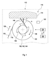
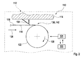
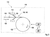
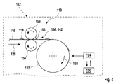
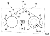
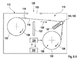
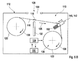
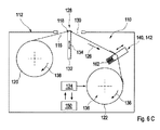
分析用検査機器(112)において使用されるマガジン(110)が提案される。このマガジン(110)は、交換可能なマガジン(110)として実施される。このマガジン(110)は、担体テープ(116)上に複数の分析用補助具(118)を備える。分析用補助具(118)は、担体テープ(116)によって、マガジン(110)の、少なくとも1つの適用位置(128)において利用可能とすることができる。マガジン(110)はさらに、未使用の分析用補助具(118)を備えた担体テープ(116)の領域を保持するための、少なくとも1つの供給リール(120)、および、使用済みの分析用補助具(118)を備えた担体テープ(116)の領域を保持するための、少なくとも1つの巻き取りリール(122)を備える。担体テープ(116)は、供給リール(120)から巻き取りリール(122)へ、スプーリング方向(126)に移動することができる。マガジン(110)は、巻き取りリール(122)の巻き戻しロック(136)を有する。マガジン(110)はさらに、テープリリース装置(142)を有し、このテープリリース装置(142)は、巻き取りリール(122)を向いた適用位置(128)側で、担体テープ(116)の巻き取りリールテープ予備分を利用可能とするように構成される。巻き取りリールテープ予備分は、好ましくは、適用位置(128)に位置付けられた分析用補助具(118)のリフト動作(134)を可能にする。 A magazine (110) is proposed for use in analytical testing equipment (112). This magazine (110) is implemented as a replaceable magazine (110). The magazine (110) comprises a plurality of analytical aids (118) on a carrier tape (116). The analytical aid (118) may be made available at at least one application location (128) of the magazine (110) by means of a carrier tape (116). The magazine (110) further includes at least one supply reel (120) for holding an area of the carrier tape (116) with unused analytical aids (118), and used analytical aids. At least one take-up reel (122) is provided for holding the area of the carrier tape (116) with the tool (118). The carrier tape (116) can move in the spooling direction (126) from the supply reel (120) to the take-up reel (122). The magazine (110) has a rewind lock (136) for the take-up reel (122). The magazine (110) further comprises a tape release device (142) which is wound on the carrier tape (116) on the application position (128) side facing the take-up reel (122). The take-up reel tape reserve is configured to be available. The take-up reel tape reserve preferably allows for a lift operation (134) of the analytical aid (118) positioned at the application position (128).
Description
本発明は、分析用検査機器において使用するマガジンと、分析用検査機器とに関する。こうした分析用検査機器およびマガジンは、具体的には、体液の試料を作成および/または採取および/または分析するために、医療診断の分野において使用される。試料分析には、具体的には、1つまたは2つ以上の検体について、体液の試料の質的または量的な分析が含まれうる。例として、このような検体は、代謝物質であってよい。さらなる、考えられる適用分野に制限されず、こうした検体は、たとえば、血糖、コレステロール、トリグリセリド、血餅などとすることができる。 The present invention relates to a magazine used in an analytical inspection instrument and an analytical inspection instrument. Such analytical test instruments and magazines are used in particular in the field of medical diagnostics to create and / or collect and / or analyze samples of body fluids. Sample analysis can specifically include qualitative or quantitative analysis of a sample of body fluid for one or more analytes. As an example, such an analyte may be a metabolite. Without being limited to further possible fields of application, such specimens can be, for example, blood sugar, cholesterol, triglycerides, clots and the like.
医療技術の分野においては、特に分析学において、分析用補助具を必要とする複数の検査機器が開示されている。例として、複数のランセットが連続的に使用可能である穿刺器具、または、体液試料において少なくとも一つの検体を検出するために、複数のテストエレメントが連続的に利用可能となりうる分析用測定器が知られる。 In the field of medical technology, a plurality of testing instruments that require an analytical aid are disclosed, particularly in analytical sciences. Examples include puncture devices in which multiple lancets can be used continuously, or analytical measuring instruments in which multiple test elements can be used continuously to detect at least one analyte in a body fluid sample. It is done.
ドラムマガジン、または、分析用補助具を利用可能にするための、同様の供給装置を有する検査機器に加えて、最近は、テープ機器の使用がますます増加している。ここで、1つまたは2つ以上の担体テープによって分析用補助具が利用可能となるのである。したがって、たとえば、特許文献1には、血液を採取するための穿刺装置について記載されている。この穿刺装置は、テープマガジンを備える。この場合、個別のランセットは、テープ上に連続して一列に並ぶ。同様に、特許文献2は、試験紙用のテープマガジンを備えた血糖測定器について記載している。2009年2月には、ロシュ・ダイアグノスティックスGmbHからのACCU−Chek(登録商標)モバイル検査機器が、試験紙テープカセットを使用する血糖測定器としては初めて市販された。 In addition to inspection equipment with similar supply devices to make drum magazines or analytical aids available, the use of tape equipment has been increasing recently. Here, one or two or more carrier tapes make the analysis aid available. Therefore, for example, Patent Document 1 describes a puncture device for collecting blood. The puncture device includes a tape magazine. In this case, the individual lancets are continuously arranged in a line on the tape. Similarly, Patent Document 2 describes a blood glucose meter equipped with a tape magazine for test paper. In February 2009, the ACCU-Chek® mobile testing device from Roche Diagnostics GmbH was first marketed as a blood glucose meter using a test strip tape cassette.
ランセット用であっても、あるいはテストエレメント用であっても、テープのコンセプトによる利点は、一般的に、比較的小型のマガジンにおいて、巻き取り形式で利用可能となりうる、たとえば、テストエレメントおよび/または穿刺要素といった、比較的多数の分析用補助具を有することである。しかし、ここで、リジッドな担体要素と比較して、一般的に、実際にはテープは比較的扱いにくいという問題がある。したがって、具体的には、テープ機器は、テープを整然とガイドするために、および、たとえば、テープの巻きが制御されずにほどけるのを防ぐために、いくつかの技術的手段を追加で必要とする。 The advantages of the tape concept, whether for lancets or for test elements, can generally be made available in roll-up form in relatively small magazines, for example test elements and / or Having a relatively large number of analytical aids, such as piercing elements. However, here, in general, there is a problem that, in comparison with a rigid carrier element, a tape is actually relatively difficult to handle. Thus, specifically, the tape equipment requires some additional technical means to guide the tape in an orderly manner and to prevent, for example, unwinding of the tape winding. .
先行技術は、特に、検査機器からマガジンが取り出される際に、担体テープを固定することができる、テープマガジン用のいわゆる巻き戻しロックを開示している。これは、すでに使用済みのテストエレメントおよび/または穿刺要素が再び出てくるのを防ぐことによって、ユーザーおよび/または分析用検査機器の他の部品が、液体の試料で不要に汚染されるリスクを回避し、またはユーザーを傷つけるのを防ぐ。 The prior art discloses so-called rewind locks for tape magazines, in which the carrier tape can be fixed in particular when the magazine is removed from the inspection device. This prevents the user and / or other parts of the analytical test equipment from being unnecessarily contaminated with liquid samples by preventing the used test elements and / or puncture elements from coming out again. Avoid or prevent hurting the user.
したがって、たとえば、特許文献3は、テストセンサーディスクマガジンを備えた測定器について記載している。このディスクマガジンは、マガジンが取り出された状態でのみ作動する巻き戻しロックを有し、逆に、このロックは、挿入状態ではバイパスされる。
Therefore, for example,
特許文献4は、診断用テストストリップのテープカセットについて記載している。このカセットは、不用意にテストテープの巻きが解けるのを防ぐべきロック用の歯を備えた回転式の安全装置を有する。このロックは、機器に依存しない取扱いの場合に作動する。 Patent Document 4 describes a tape cassette for a diagnostic test strip. This cassette has a rotating safety device with locking teeth to prevent inadvertent unwinding of the test tape. This lock is activated in case of handling independent of the device.
特許文献5は、テストストリップテープマガジンを備えた血糖測定システムについて記載している。歯止めによって、巻き取りリール、つまり、テストテープの使用済みテープ部分用の保持リールが、一方向にのみ回転できるようになる。このロック機能は、マガジンが挿入されている状態でアクティブとなる。 Patent Document 5 describes a blood glucose measurement system provided with a test strip tape magazine. The pawl allows the take-up reel, i.e. the holding reel for the used tape part of the test tape, to rotate in only one direction. This lock function is active when a magazine is inserted.
特許文献6もまた、穿刺補助具について記載している。この穿刺補助具は、一体型の巻き戻しロックを備えたランセットマガジンを有する。この巻き戻しロックは、具体的には、その時以前に使用されたランセットの再利用を防ぐべきものである。 Patent Document 6 also describes a puncture assisting device. This lancing aid has a lancet magazine with an integral rewind lock. This rewind lock should specifically prevent reuse of the lancet that was previously used.
特許文献7は、テープマガジン上に格納されるマイクロサンプラーに基づいたシステムについて記載している。このシステムもまた、巻き戻しロックを備えている。ラチェット装置によって、テープ移送を前方向のみに行うことができる。このようにして、挿入されたテープマガジンが、不用意な巻き戻しに対して安定する。 U.S. Pat. No. 6,057,049 describes a system based on a microsampler stored on a tape magazine. This system also has a rewind lock. With the ratchet device, the tape can be transferred only in the forward direction. In this way, the inserted tape magazine is stable against inadvertent rewinding.
特許文献8は、液体試料を得るための試料採取システム用のコンビネーションドライブを開示している。この試料採取システムは、結合要素を備え、分析用補助具、および、この結合要素の移動を駆動するためのドライブユニットに結合する。ドライブユニットはさらに、少なくとも1つの回転方向感知要素を備えた結合装置を有し、この結合装置は、エネルギー変換器を、第一の回転方向において第一システム機能に結合し、第二の回転方向において第二システム機能に結合するように構成される。 Patent Literature 8 discloses a combination drive for a sampling system for obtaining a liquid sample. The sampling system comprises a coupling element and is coupled to an analytical aid and a drive unit for driving movement of the coupling element. The drive unit further comprises a coupling device with at least one rotational direction sensing element, which couples the energy converter to the first system function in the first rotational direction and in the second rotational direction. Configured to couple to a second system function.
しかし、実際には、テープマガジンの使用に基づいた公知の検査機器には、いくつかの技術的な課題がある。具体的には、そこに分析用補助具が位置付けられた少なくとも1つの適用位置において、リフト動作が実行される検査機器がある。例として、このリフト動作は、迅速に実行される穿刺動作および/または、ゆっくりと実行される試料採取動作とすることができる。したがって、たとえば、ランセットを使用することによってユーザーの皮膚部分に穿刺することができ、および/または、適用位置において、テストエレメントを使って、体液の液体試料を採取することができる。しかし、このような、テープマガジン上に格納された分析用補助具のリフト動作の場合の問題は、テープのリリースにある。例として、教示された担体テープは、穿刺または血液採取の手順に対して、限られた好適性を有しているだけである。テープをリリースすることにより、担体テープも動かしてしまうリフト動作の際に、テープのたわみが可能になり、その結果、担体テープの過剰な伸び、永久変形、または、破れさえも回避する。 In practice, however, known inspection equipment based on the use of tape magazines has several technical challenges. Specifically, there is an inspection device in which a lift operation is performed in at least one application position where an analytical aid is located. As an example, the lift operation may be a puncture operation that is performed quickly and / or a sampling operation that is performed slowly. Thus, for example, a user's skin portion can be punctured by using a lancet and / or a fluid sample of bodily fluid can be taken at the application location using a test element. However, the problem with the lifting operation of the analytical aid stored on the tape magazine is the release of the tape. As an example, the taught carrier tape has only limited suitability for puncture or blood collection procedures. By releasing the tape, it is possible for the tape to bend during a lift operation that also moves the carrier tape, thus avoiding excessive stretching, permanent deformation or even tearing of the carrier tape.
特許文献9は、複数のランセットを運ぶランセット担体テープを備えた穿刺システムについて記載している。穿刺動作において、穿刺ドライブは、穿刺位置に移動されたランセットを、このランセットを担持するランセット担体テープの一部とともに、穿刺方向に動かす。ランセットが穿刺位置に移動された後、搬送方向において穿刺位置の後方に配された移送装置の少なくとも1つの部分が、前記ランセットの穿刺動作の前またはその間、動作を実行する。さらに、挿入されたカセット上の巻き取り装置は、それぞれの穿刺動作用に、巻き取りリールから担体テープの巻きを解くために巻き戻し工程を実行することが提案されている。 Patent document 9 describes a puncture system provided with a lancet carrier tape carrying a plurality of lancets. In the puncturing operation, the puncture drive moves the lancet moved to the puncture position together with a part of the lancet carrier tape carrying the lancet in the puncture direction. After the lancet is moved to the puncture position, at least one part of the transfer device arranged behind the puncture position in the transport direction performs an operation before or during the puncture operation of the lancet. Furthermore, it has been proposed that the take-up device on the inserted cassette performs a rewinding process to unwind the carrier tape from the take-up reel for each puncturing operation.
したがって、一般的に、マガジンに格納されたランセット、テストエレメントまたはマイクロサンプラーは、医療機器を取り扱う際に必要な衛生状態および安全性をユーザーに提供するためには、一般的に、巻き戻しロックを必要とすることに留意する必要がある。こうした巻き戻しロックは、原理的には、テープマガジンに格納された分析用補助具に適用されうる。しかし、公知のシステムの欠点は、巻き戻しロックが存在することが、テープリリースの必要条件、つまり、たとえば穿刺または試料採取の工程の間など、リフト動作の間、逆方向にテープの巻きを解くこととは相反することが多いという事実である。しかし、多くの場合、テープリリースは、既に巻き取りリールに巻き取られた担体テープの巻き戻しを必要とする。なぜなら、そうしなければ、テストシステム、たとえばランセットグリッパーの作動システムにおいて、不均等な負荷が生じることになるからである。例として、この結果は、穿刺が斜めになったり、グリッパー内のランセットが滑ったり、穿刺作動システムを妨害したりなどということになる。 Therefore, in general, a lancet, test element or microsampler stored in a magazine generally has a rewind lock in order to provide the user with the necessary hygiene and safety when handling medical devices. It is necessary to keep in mind that it is necessary. Such a rewind lock can in principle be applied to an analytical aid stored in a tape magazine. However, a disadvantage of the known system is that the presence of the rewind lock unwinds the tape in the reverse direction during the lift operation, ie during the tape release requirement, ie during the puncture or sampling process, for example. This is a fact that often conflicts. However, in many cases, tape release requires the rewinding of a carrier tape that has already been wound on a take-up reel. Otherwise, unequal loads will occur in the test system, for example the operating system of the lancet gripper. As an example, this result may be that the puncture is slanted, the lancet in the gripper slips, interferes with the puncture actuation system, and so on.
十分な遊びをもって、穿刺工程においてたわむ必要がある、たわむ担体テープを提供するために、多くの場合、テープのリリースが必要とされる。しかし、このための、先行技術から公知となるほとんどの解決策は、巻き戻しロックの存在に対する答えをもたらすことはない。マガジンの巻き戻しロックが、こうした機能をサポートしないのであれば、または、テープのリリースのための他の代替手段が提供されなければ、巻き取りリール駆動部のアクティブな巻き戻し動作では、多くの場合、十分でない。 In order to provide a flexible carrier tape that needs to bend in the puncture process with sufficient play, often a release of the tape is required. However, most solutions known from the prior art for this do not provide an answer to the existence of a rewind lock. The active rewind operation of the take-up reel drive is often the case if the magazine rewind lock does not support these functions or if no other alternative for tape release is provided. ,not enough.
したがって、常時作用する、一体型の巻き戻しロックを備えた検査機器およびテープマガジンの場合は特に、テストエレメントのリフト動作とは目的が矛盾することが確認できる。ここで、一体型の巻き戻しロックは、マガジンに一体化されているため、このように検査機器の駆動部を必要とすることなく、巻き戻しを防ぐことができる巻き戻しロックを意味すると一般的に理解されるべきである。一方では、マガジンが検査機器から分離している場合でも、巻き取りリールから担体テープの巻きが不用意に解かれることを防ぐため、このような一体型の巻き戻しロックが望ましいことが多い。しかし、他方では、たとえば、テストエレメントの張力がかかっていないリフト動作を可能にするために、供給リールおよび巻き取りリールから整然と、担体テープの巻きが均等に解けることを必要とするのは、正確なリフト動作である。 Therefore, it can be confirmed that the purpose is contradictory to the lift operation of the test element, particularly in the case of the inspection device and the tape magazine that are always operated and have an integral rewinding lock. Here, since the integrated rewind lock is integrated with the magazine, it generally means a rewind lock that can prevent rewinding without requiring a drive unit for the inspection device. Should be understood. On the other hand, even when the magazine is separated from the inspection device, such an integral rewind lock is often desirable to prevent the carrier tape from being unintentionally unwound from the take-up reel. On the other hand, however, it is accurate to require that the carrier tape be unwound in an orderly manner from the supply reel and the take-up reel, for example, to allow an untensioned lift of the test element. Lift operation.
マガジンが検査機器に挿入される際に巻き戻しロックがバイパスされる、たとえば、特許文献10における解決手段のように、先行技術から公知の解決手段は、部分的に、技術的に非常に複雑である。さらに、一般的に、このようなリリースによって、穿刺後、リリースされたテープ材料がゆるく固定されることになり、テープガイドがとれてしまう可能性がある。これに対応した、巻き取りリール駆動部の複雑な制御によって、こうした状況を補うことができる。 The solution known from the prior art is partially technically very complicated, for example the solution in US Pat. is there. Furthermore, in general, such a release will loosely fix the released tape material after puncturing, and the tape guide may be removed. Corresponding to this, complicated control of the take-up reel drive unit can compensate for this situation.
したがって、本発明の目的は、公知のマガジンと分析用検査機器の欠点を少なくとも大部分は回避できる、マガジンと分析用検査機器を提供することである。特に、上述のような、巻き戻しロックとテープのリリースとの間の目的の矛盾は、技術的に簡単な方法で解決する必要がある。 Accordingly, it is an object of the present invention to provide a magazine and analytical testing instrument that can avoid at least most of the disadvantages of known magazines and analytical testing equipment. In particular, the conflict of purpose between the rewind lock and the release of the tape as described above needs to be solved in a technically simple manner.
独立請求項の特徴を有する本発明によって、この目的は達成される。個別に、または組み合わせて実施できる、本発明の有利な展開は、従属請求項において例示されている。 This object is achieved by the present invention having the features of the independent claims. Advantageous developments of the invention that can be implemented individually or in combination are exemplified in the dependent claims.
本発明の第一の態様において、分析用検査機器において使用されるマガジンが提案される。ここで、マガジンとは、複数の分析用補助具を保持し、利用可能にできるような装置を意味すると理解されるべきである。マガジンは、以下により詳細に説明するが、より具体的には、テープマガジン、たとえば、テープカセットとして実施され、一般的には、たとえばマガジンハウジングを有することができる。 In a first aspect of the invention, a magazine for use in an analytical testing instrument is proposed. Here, a magazine should be understood to mean a device that can hold and make available a plurality of analytical aids. The magazine is described in more detail below, but more specifically is implemented as a tape magazine, eg, a tape cassette, and can generally have, for example, a magazine housing.
一般的に、分析用検査機器は、少なくとも1つの医療的機能、より具体的には、分析および/または診断的機能を実行することができる機器を意味すると理解されるべきである。具体的には、分析用検査機器は、以下のような機能の1つまたは2つ以上を実行できる。体液の試料の生成。より具体的には、ユーザーの皮膚片を穿刺することによって、生成すること。体液からの試料において少なくとも1つの検体を検出すること、より具体的には、血糖および/またはコレステロールおよび/またはトリグリセリドの検出、および/または凝固物の検出。体液の試料を、より具体的には、毛細管作用によって採取すること。 In general, analytical testing equipment should be understood to mean equipment capable of performing at least one medical function, more specifically analytical and / or diagnostic functions. Specifically, the analytical testing instrument can perform one or more of the following functions. Generation of body fluid samples. More specifically, generating by puncturing the user's skin piece. Detecting at least one analyte in a sample from a body fluid, more specifically detecting blood glucose and / or cholesterol and / or triglycerides, and / or detecting coagulum. Collect bodily fluid samples, more specifically by capillary action.
このマガジンは、交換式のマガジンとして実施される。つまり、ユーザーは、新しい、未使用のマガジンを分析用検査機器に挿入するために、分析用検査機器からマガジンを取り出すことができる。例として、分析用検査機器はこの目的のための受容部を備えていてよく、たとえば、検査機器のハウジングを開いた後で、マガジンをこの受容部に挿入、または、マガジンでこの受容部を塞ぐことができる。したがって、マガジンは常時分析用検査機器に接続されているわけではない。例として、上述の医療的機能が、こうした作動システムを有してよい分析用検査機器と併せてのみ実行できるように、マガジン自体は、独自の作動システムを有していなくてもよく、または、部分的な作動システムを有するだけでよい。さらに、マガジンのマガジンハウジングは、マガジンの分析用検査機器への抜去可能な挿入、および/または、マガジンの分析用検査機器への取り外し可能な取り付けを可能にするために、たとえば、対応するガイド、溝、固定要素、または位置決め用補助具を有してよい。 This magazine is implemented as a replaceable magazine. In other words, the user can take out the magazine from the analytical testing device in order to insert a new, unused magazine into the analytical testing device. By way of example, an analytical test instrument may be provided with a receptacle for this purpose, for example after opening the housing of the test instrument, a magazine is inserted into this receptacle or the magazine is closed with this receptacle. be able to. Therefore, the magazine is not always connected to the analytical testing equipment. By way of example, the magazine itself may not have its own actuation system so that the medical functions described above can only be performed in conjunction with analytical testing equipment that may have such an actuation system, or It is only necessary to have a partial actuation system. In addition, the magazine housing of the magazine may be used, for example, with a corresponding guide, to allow removable insertion of the magazine into the analytical test equipment and / or removable attachment of the magazine to the analytical test equipment. It may have a groove, a fixing element, or a positioning aid.
マガジンは、担体テープ上に複数の分析用補助具を有する。ここで、分析用補助具は、分析用検査機器の少なくとも1つの医療的機能のために使用できる補助具を意味すると理解されるべきである。具体的には、これは試料生成機能および/または試料採取機能および/または分析機能であってよい。したがって、分析用補助具は、以下のような分析用補助具の1つまたは2つ以上を備えてよい。ランセット、言い換えれば、ユーザーの皮膚片を穿刺および/または切開または一般的に穿孔するための要素。ユーザーからの体液の試料を保持し、搬送するための要素、より具体的には、毛細管および/または毛細管間隙。体液における少なくとも1つの検体を検出するための少なくとも1つの検査用化学物質を有するテストエレメント。例として、少なくとも1つの検出すべき検体の存在下で、検査用化学物質は、少なくとも1つの物理的および/または化学的に検出可能な特性を変化させる材料とすることができる。こうした検査用化学物質は、先行技術から公知である。例として、テストエレメントは、電子化学的および/または光学的テストエレメントとすることができる。例として、テストエレメントは、少なくとも1つのテストフィールドを備えることができる。ここで、分析マガジンは、単に、1タイプの分析用補助具が利用可能になるように実施することができる。あるいは、たとえば、交互に行うなど、複数のタイプの分析用補助具を利用可能にすることも可能である。上記の複数の機能を統合する、一体型の分析用補助具が存在することも可能である。したがって、たとえば、ランセット機能および毛細管機能を備え、その上、本発明の範囲内で分析用補助具として使用することができる、マイクロサンプラーが知られている。たとえば任意で追加的な毛細管を備えた、テストエレメントを備えた一体型のランセットもまたあり得る。 The magazine has a plurality of analytical aids on the carrier tape. Here, analytical aids are to be understood as meaning aids that can be used for at least one medical function of the analytical testing instrument. Specifically, this may be a sample generation function and / or a sampling function and / or an analysis function. Therefore, the analysis aid may include one or more of the following analysis aids. Lancet, in other words, an element for puncturing and / or incising or generally perforating a user's skin piece. An element for holding and transporting a sample of bodily fluid from a user, more specifically a capillary and / or capillary gap. A test element having at least one test chemical for detecting at least one analyte in a body fluid. By way of example, in the presence of at least one analyte to be detected, the test chemical may be a material that changes at least one physically and / or chemically detectable property. Such test chemicals are known from the prior art. By way of example, the test element can be an electrochemical and / or optical test element. As an example, a test element can comprise at least one test field. Here, the analysis magazine can simply be implemented so that one type of analysis aid is available. Alternatively, a plurality of types of analysis aids can be made available, for example, alternately. There can also be an integrated analytical aid that integrates the above functions. Thus, for example, microsamplers are known that have a lancet function and a capillary function and can be used as an analytical aid within the scope of the present invention. There can also be an integrated lancet with test elements, optionally with additional capillaries.
一般的に、担体テープは、連続した支持体であり、これによって分析用補助具が連続して利用可能になり得るものであると理解されるべきである。したがって、たとえば紙テープ、プラスチック製のテープ、多層ラミネートテープまたは同様のテープといったシンプルなテープに加えて、たとえば、リンクチェーンなど、他のタイプの連続した支持体もまたあり得る。例として、分析用補助具は担体テープ上に配置、および/または担体テープと一体化、および/または、他の方法で担体テープと接続することができる。例として、分析用補助具は、等距離間隔で担体テープに配することができる。したがって、たとえば、ランセットは担体テープ上に配することができ、および/または、テストエレメントは担体テープに、たとえば、テストフィールドという形態で配することができる。 In general, it should be understood that the carrier tape is a continuous support by which the analytical aid can be continuously available. Thus, in addition to simple tapes such as paper tapes, plastic tapes, multilayer laminate tapes or similar tapes, there can also be other types of continuous supports such as link chains. By way of example, the analytical aid can be placed on and / or integrated with the carrier tape and / or otherwise connected to the carrier tape. As an example, the analytical aids can be placed on the carrier tape at equidistant intervals. Thus, for example, the lancet can be arranged on a carrier tape and / or the test element can be arranged on the carrier tape, for example in the form of a test field.
マガジンの少なくとも1つの適用位置において分析用補助具を利用可能にするために、担体テープを使用することができる。ここで、適用位置は、分析用検査機器の少なくとも1つの機能が、分析用補助具と相互作用する位置であり、この適用位置に分析用補助具が位置付けられていると理解されるべきである。例として、この適用位置は、ランセットが穿刺動作および/または試料採取動作を行う位置とすることができる。代わりに、またはこれに追加して、適用位置は、試料取得動作が実行される位置とすることができる。例として、分析用検査機器の作動システムは、より詳細については以下に説明するとおり、この機能を実行するために設けることができる。 A carrier tape can be used to make the analytical aid available at at least one application location of the magazine. Here, it should be understood that the application position is a position where at least one function of the analytical testing instrument interacts with the analytical auxiliary tool, and the analytical auxiliary tool is positioned at this application position. . As an example, the application position may be a position where the lancet performs a puncturing operation and / or a sampling operation. Alternatively or additionally, the application position can be a position where a sample acquisition operation is performed. By way of example, an analytical test instrument actuation system may be provided to perform this function, as described in more detail below.
例として、担体テープを使用することによって、少なくとも1つの適用位置において分析用補助具を連続して利用可能にするように、分析マガジンおよび分析用検査機器を実施することができる。複数の適用位置、たとえば、試料を取得する適用位置および試料を評価するための適用位置を設けることもできる。例として、新しい、未だ使われていない分析用補助具をそれぞれ、マガジンの適用位置において利用可能にできるように、担体テープを巻き取ることができる。 By way of example, the analysis magazine and the analytical testing instrument can be implemented such that by using a carrier tape, the analytical aid is continuously available in at least one application location. It is also possible to provide a plurality of application positions, for example an application position for obtaining a sample and an application position for evaluating the sample. As an example, the carrier tape can be wound so that each new, yet unused analytical aid can be made available at the application location of the magazine.
マガジンはさらに、未使用の分析用補助具を備えた担体テープの領域を保持するための少なくとも1つの供給リール、および、使用済みの分析用補助具を備えた担体テープの領域を保持するための少なくとも1つの巻き取りリールも有する。したがって、巻き取りリールおよび/または供給リールを、搬送機構によって駆動するように、分析用検査機器を構成することによって、新しい、未使用の分析用補助具が、適用位置において利用可能となるように、担体テープをそれぞれ巻き取ることができる。したがって、分析用検査機器は、好ましくは、巻き取りリールを、具体的には、回転運動として、より具体的には、周期的な回転運動として駆動できる駆動部を備える。担体テープの、こうした前方への搬送は、一般的には、以下のように「スプーリング」ともいわれる。担体テープは、供給リールから巻き取りリールへと、スプーリングの方向に移動する。 The magazine further includes at least one supply reel for holding an area of the carrier tape with unused analytical aids, and an area for the carrier tape with used analytical aids. It also has at least one take-up reel. Thus, by configuring the analytical test equipment to drive the take-up reel and / or supply reel by the transport mechanism, a new, unused analytical aid is made available at the application location. Each carrier tape can be wound up. Accordingly, the analytical testing instrument preferably includes a drive unit that can drive the take-up reel, specifically, as a rotational motion, more specifically, as a periodic rotational motion. Such forward transport of the carrier tape is generally referred to as “spooling” as follows. The carrier tape moves in the direction of spooling from the supply reel to the take-up reel.
マガジンはさらに、巻き取りリールの巻き戻しロックを有する。全体的または部分的にマガジンに一体化できる、この巻き戻しロックは、巻き取りリールの巻き戻し、つまりは、すでに使用された、つまりは使用済みの分析用補助具が、少なくとも再度適用位置に到達するような程度まで、担体テープがスプーリングとは反対の方向へと移動することを防ぐ装置であると理解されるべきである。したがって、巻き戻しロックは、必ずしも、巻き取りリールの巻き戻しを完全に防ぐように実施する必要はなく、以下に、より詳細に説明するとおり、むしろ、軽微な巻き戻しを許容してよいし、またはこれを促進すらしてよい。しかし、すでに使用された分析用補助具が再度適用位置に到達する程度まで、こうした巻き戻しを可能とするべきではない。あるいは、巻き戻しを完全に防ぐように、巻き戻しロックを実施することもできる。 The magazine further has a take-up reel rewind lock. This rewind lock, which can be integrated into the magazine in whole or in part, allows the take-up reel to be rewinded, i.e. the analytical tools that have already been used, i.e. used, at least again reach the application position. To the extent that it does, it should be understood that the device prevents the carrier tape from moving in the opposite direction to spooling. Thus, the rewind lock need not necessarily be implemented to completely prevent rewinding of the take-up reel, but rather may allow minor rewinding, as described in more detail below, Or you may even promote this. However, such rewinding should not be possible to the extent that the analytical aid already used reaches the application position again. Alternatively, a rewind lock can be implemented to completely prevent rewind.
以下に、より詳細に説明するとおり、巻き戻しロックがマガジンの一部であるということは、本発明によるマガジンの利点となる。なぜなら、巻き戻しロックがマガジンに一体化することによって、たとえば使用済みのテープカセットといった、使用済み、かつ、取り出し済みのマガジンにおける、すでに使用済みの分析用補助具の巻き戻し、および、テープの、望ましくない、制御されない巻きの解けを確実に妨げることが可能になるからである。 As will be explained in more detail below, it is an advantage of the magazine according to the invention that the rewind lock is part of the magazine. Because the rewind lock is integrated into the magazine, for example, rewinding of already used analytical aids in a used and removed magazine, such as a used tape cassette, This is because undesired uncontrolled winding can be surely prevented.
マガジンはさらに、巻き取りリールを向いた適用位置側に、担体テープの巻き取りリールテープ予備分を利用可能にするように構成されるテープリリース装置を有する。したがって、巻き取りリールを向いた適用位置側とは、スプーリング方向において適用位置をすでに通過しており、そのために、巻き取りリールに向かって移動するか、または、すでに巻き取りリールに巻き取られている、担体テープの部分を意味すると理解されるべきである。 The magazine further has a tape release device configured to make available a take-up reel tape reserve of the carrier tape on the application position side facing the take-up reel. Therefore, the application position side facing the take-up reel has already passed through the application position in the spooling direction and therefore moves towards the take-up reel or is already taken up by the take-up reel. Is to be understood as meaning the part of the carrier tape.
具体的には、巻き取りリールテープ予備分は、それ自体で、または、供給リールを向いた適用位置側のテープ予備分と相互作用することによって、適用位置に位置付けられた分析用補助具のリフト動作を可能にすることができる。したがって、一般的に、テープ予備分は、担体テープの変形または破れにつながる恐れのある、担体テープに働く大きな張力がない状態で、この分析用補助具に接続された担体テープの部分を含んだ分析用補助具のリフト動作を可能にするようなテープ部分を意味すると理解されるべきである。したがって、テープ予備分は、リフト動作用に追加で必要とされる担体テープを利用可能にできるテープ部分である。ここで、適用位置の巻き取りリール側のテープ予備分は、一般的に巻き取りリールテープ予備分とされ、供給リールテープ予備分は、適用位置の供給リール側の任意の追加のテープ予備分を指す。 Specifically, the take-up reel tape reserve is lifted by the analytical aid positioned at the application position by itself or by interacting with the tape reserve on the application position side facing the supply reel. Operation can be enabled. Thus, in general, the tape reserve included the portion of the carrier tape connected to this analytical aid in the absence of significant tension acting on the carrier tape that could lead to deformation or tearing of the carrier tape. It should be understood to mean a portion of the tape that allows the lift operation of the analytical aid. Thus, the tape reserve is the portion of the tape that can make available the additional carrier tape needed for the lift operation. Here, the tape reserve on the take-up reel side at the application position is generally a take-up reel tape reserve, and the supply reel tape reserve is an optional additional tape reserve on the supply reel side in the application position. Point to.
したがって、マガジンは、より具体的には、担体テープの供給リールテープ予備分が、供給リール自体を含みうる、供給リールを向いた適用位置側で、追加で利用可能になり得るように、実施することができる。好ましくは、供給リールテープ予備分が巻き取りリールテープ予備分に実質的に一致するように、マガジンは構成される。ここで、「実質的に」は、これらのテープ予備分が完全に一致していることを意味すると好ましくは理解されるべきであるが、この用語の範囲内において、30%だけの、より具体的には、20%だけの、特に好ましくは、10%だけの誤差を許容することもできる。 Thus, the magazine is more specifically implemented so that the supply reel tape reserve of the carrier tape may additionally be available on the application position side facing the supply reel, which may include the supply reel itself. be able to. Preferably, the magazine is configured such that the supply reel tape reserve substantially coincides with the take-up reel tape reserve. Here, “substantially” should preferably be understood to mean that these tape reserves are perfectly matched, but within the scope of this term, only 30% more specific. In particular, an error of only 20%, particularly preferably only 10%, can be tolerated.
したがって、たとえば、巻き取りリールテープ予備分、および、任意で供給リールテープ予備分から構成され得るテープ予備分全体が、好ましくは、対称的な実施態様を有することが好ましく、好ましくは、等しい寸法でこれら2つのテープ予備分が構成されるように、マガジンを構成することができる。この結果として、たとえば、作動部および/またはグリッパーを一様にロードすることが可能である。例として、こうすることによって、少なくとも部分的に、詰まり、および/または、リフト動作の傾き、たとえば穿刺の傾きを防ぐことが可能となる。 Thus, for example, the entire tape reserve, which may be composed of a take-up reel tape reserve and optionally a supply reel tape reserve, preferably has a symmetrical embodiment, preferably with equal dimensions. The magazine can be configured such that two tape reserves are configured. As a result of this, it is possible, for example, to load the actuator and / or the gripper uniformly. By way of example, this makes it possible, at least in part, to prevent clogging and / or tilting of the lifting movement, for example tilting of the puncture.
供給リールを向いた適用位置側で、供給リール自体が、供給リールテープ予備分を利用可能にすることが可能である。なぜなら、供給リールは、いずれの場合も、テープリリースを許容できるからであるが、これは、こうしたテープリリースの際、供給リールは、通常の回転方向において回転するためであり、この回転は、前方循環動作の際に起こる。 On the application position side facing the supply reel, the supply reel itself can make the supply reel tape reserve available. This is because the supply reel can tolerate tape release in any case, because during such tape release, the supply reel rotates in the normal direction of rotation, Occurs during cyclic operation.
ここで、一般的に、リフト動作は、適用位置における分析用補助具の動作であって、分析用検査機器における、分析用補助具の正しい使用中に起こるものであると理解されるべきである。例として、分析用補助具は、リフト動作の間、たとえば、適用位置において少なくとも1つのグリッパーによって、固定されてよい。例として、リフト動作は、穿刺動作および/または試料取得動作とすることができる。例として、ランセットは、分析用検査機器のグリッパーによって、穿刺動作の形態をとるリフト動作に使用できる。そして、こうしたリフト動作は、たとえば、最高2〜5m/秒の速度の急速な前進動作を含み、この間、皮膚片は穿刺され、その後、後退動作が行われる。また、後退動作中に、たとえば、毛細管間隙によって、試料を取得することも可能である。代りに、試料取得動作の形態をとるリフト動作は、ユーザーの皮膚表面上の創傷部および/または試料までのテストフィールドの前進動作を含んでよく、この間、テストフィールドまたはテストエレメントは、液体試料に少しの間接触することによって、液体試料は、テストフィールドに適用される。例として、この試料取得動作は、たとえば、最高1m/秒未満、たとえば、速度0.01〜0.5m/秒の速度でのゆっくりしたものであってよい。例として、グリッパーおよび/または他のタイプの作動部もまた、このために使用できる。 Here, it should be understood that in general, the lift operation is the operation of the analytical aid in the application position and occurs during the correct use of the analytical aid in the analytical testing instrument. . As an example, the analytical aid may be secured during the lift operation, for example by at least one gripper in the application position. As an example, the lift operation can be a puncture operation and / or a sample acquisition operation. As an example, the lancet can be used in a lift operation in the form of a puncture operation by a gripper of an analytical test instrument. Such a lift operation includes, for example, a rapid advance operation at a speed of up to 2 to 5 m / sec. During this time, the skin piece is punctured, and then a retract operation is performed. It is also possible to obtain a sample during the retraction operation, for example, by a capillary gap. Alternatively, the lift operation, which takes the form of a sample acquisition operation, may include an advance operation of the test field to the wound and / or sample on the user's skin surface, during which the test field or test element is applied to the liquid sample. By touching for a moment, the liquid sample is applied to the test field. By way of example, this sample acquisition operation may be slow, for example at a speed of up to less than 1 m / s, for example a speed of 0.01 to 0.5 m / s. As an example, grippers and / or other types of actuators can also be used for this purpose.
一般的に、適用位置に位置付けられた分析用補助具のリフト動作は、たとえば、固定値として規定されてよい、または調節可能に実施してもよい、最大持ち上げ幅を有する。具体的には、巻き取りリールテープ予備分は、最大持ち上げ幅の0.2〜0.8倍、好ましくは、最大持ち上げ幅の0.5倍とすることができる。しかし、原理的に、巻き取りリールテープ予備分は、原理的に、リールの設計にしたがって、0から最大リフト幅までのすべての値をとることができる。一般的に、これは、リフト方向に対するテープガイダンスのタイプに依存するだけであり、たとえば、制限値を考慮することによって例示することができる。例として、担体テープがリフト方向に対して垂直に伸びる場合、リフト動作は、一般的に、ほとんど何の役割も果たさない。必要とされる巻き取りリールテープ予備分は、実質的に、テープの移動から取得することができる。しかし、テープが、実質的にリフト動作と平行に伸びる場合、各リール側は、一般的に、テープ予備分として、完全なリフト長さを提供する必要がある。したがって、上記のような、最大リフト幅の0.5倍という値は、実際よく見受けられる平均値となる。例として、最大リフト幅は0.5〜10mm、より具体的には、1〜8mm、好ましくは3〜6mmとすることができる。 In general, the lifting movement of the analytical aid positioned in the application position has a maximum lifting width, which may for example be defined as a fixed value or may be carried out in an adjustable manner. Specifically, the take-up reel tape reserve can be 0.2 to 0.8 times the maximum lifting width, and preferably 0.5 times the maximum lifting width. However, in principle, the take-up reel tape reserve can in principle take all values from 0 to the maximum lift width according to the reel design. In general, this only depends on the type of tape guidance relative to the lift direction and can be illustrated, for example, by considering limit values. As an example, when the carrier tape extends perpendicular to the direction of lift, the lift operation generally plays almost no role. The required take-up reel tape reserve can be substantially obtained from the movement of the tape. However, if the tape extends substantially parallel to the lift operation, each reel side generally needs to provide a full lift length as a tape reserve. Therefore, the value of 0.5 times the maximum lift width as described above is an average value that is often found in practice. As an example, the maximum lift width can be 0.5-10 mm, more specifically 1-8 mm, preferably 3-6 mm.
テープリリース装置は、さらに、分析用補助具のリフト動作後、この場合も、巻き取りリールテープ予備分を全体的にまたは少なくとも部分的に、保持するように構成できる。このために、テープリリース装置は、たとえば、テープリザーバーを備えることができ、このテープリザーバーから、リフト動作用の巻き取りリールテープ予備分が取り出され、このテープリザーバーに、巻き取りリールテープ予備分を、リフト動作後、補給することができる。例として、以下に、より詳細に説明するとおり、このテープリザーバーは、少なくとも1つの移動可能に設けられた、偏向要素の形態で実施することができる。しかし、他のタイプのテープリザーバーも可能で、より具体的には、巻き取りリールテープ予備分を利用可能にできるようにするために、適用位置と巻き取りリールとの間に保持される、様々な長さの担体テープ部分を形成できるテープリザーバーも可能である。しかし、代替案として、またはこれに加えて、テープリリース装置は、全体的にまたは部分的に、巻き取りリールに一体化することもできる。これについては、より詳細に以下に説明する。後者が、さらに、前と同じように、分析用補助具のリフト動作後に、巻き取りリールテープ予備分を保持するように構成されるような、テープリリース装置の実施態様によって、さらに、担体テープの詰まり、引っかかり、すべり、またはもつれを引きおこす可能性のある、リフト動作後に余ったテープによって生じるテープもつれを防ぐこともできる。 The tape release device can be further configured to hold the take-up reel tape reserve in whole or at least partially after the analytical auxiliary tool lift operation. For this purpose, the tape release device can be provided with, for example, a tape reservoir, from which a take-up reel tape reserve for lift operation is taken out, and the take-up reel tape reserve is taken into this tape reservoir. After the lift operation, it can be replenished. By way of example, as will be explained in more detail below, this tape reservoir can be implemented in the form of at least one movably provided deflection element. However, other types of tape reservoirs are possible, and more specifically, the various that are held between the application position and the take-up reel in order to make the take-up reel tape reserve available. Tape reservoirs that can form carrier tape portions of any length are also possible. However, as an alternative or in addition, the tape release device can also be integrated into the take-up reel in whole or in part. This will be described in more detail below. According to an embodiment of the tape release device, the latter is further configured to hold the take-up reel tape reserve after the lift operation of the analytical aid as before, It can also prevent tape entanglement caused by excess tape after the lift operation, which can cause clogging, catching, slipping or tangling.
テープリリース装置は、好ましくは、適用位置の巻き取りリール側、つまり、適用位置から見た、巻き取りリールを向いた側に設けられるだけである。適用位置および供給リールの間の、供給リールを向いた側において、そのようなテープリリース装置は設けないことが好ましい。ここで、たとえばテープ輸送中および/またはリフト動作中に、担体テープ上に十分な量の張力が働くのであれば、供給リールは、好ましくは、それ自体がテープリリースとして機能し、かつ、必要な供給リールテープ予備分を供することによって、好ましくは、供給リールを向いた適用位置側で、追加のテープリリース装置を省略することができる。言い換えれば、テープリリース装置が巻き取りリール側に設けられた状態で、適用位置の供給リール側で、供給リールだけで、テープリリース装置としての機能を果たすことができる。このテープリリース装置は、より具体的には、適用位置と巻き取りリールとの間に、および/または巻き取りリール自体において配することができる。いずれの場合も一般的に技術的効果がない、追加のテープリリース装置を、供給リール側で省略することができ、そのことが、技術的な簡素化、製造コストの低減、および設置の省スペース化に役立つことができるという点で、既知のテープガイドと比較して、この実施態様は有利である。さらに、こうすることによって、常に十分な張力のもと、テープを保持することが可能となり、適用位置と供給リールとの間の、追加のテープリリース装置による、望ましくない、このようなテープのリリースによって、供給リール側でテープの巻きが、制御されずに解けるにいたる可能性があるテープのリリースを回避することができる。 The tape release device is preferably provided only on the take-up reel side of the application position, that is, on the side facing the take-up reel as viewed from the application position. It is preferable not to provide such a tape release device on the side facing the supply reel between the application position and the supply reel. Here, if a sufficient amount of tension is exerted on the carrier tape, for example during tape transport and / or lift operation, the supply reel preferably functions as a tape release itself and is required. By providing the supply reel tape reserve, an additional tape release device can be omitted, preferably on the application position side facing the supply reel. In other words, in a state where the tape release device is provided on the take-up reel side, the function as the tape release device can be achieved only by the supply reel on the supply reel side at the application position. More specifically, the tape release device can be arranged between the application position and the take-up reel and / or on the take-up reel itself. In any case, an additional tape release device, which generally has no technical effect, can be omitted on the supply reel side, which simplifies the technology, reduces manufacturing costs and saves installation space. This embodiment is advantageous in comparison to known tape guides in that it can help in the process. In addition, this makes it possible to hold the tape under sufficient tension at all times and undesirably release such a tape by means of an additional tape release device between the application position and the supply reel. Thus, it is possible to avoid the release of the tape which may lead to unwinding of the tape on the supply reel side without being controlled.
具体的には、適用位置に位置付けられている分析用補助具が、少なくとも1つの固定装置、より具体的には、少なくとも1つのグリッパーによって固定できるように、マガジンは実施可能である。固定装置は、全体的または部分的に、マガジンの構成要素であってよいが、マガジンを使用する、および/または備える分析用検査機器に、全体的または部分的に、含まれていてもよい。 In particular, the magazine can be implemented so that the analytical aid positioned in the application position can be fixed by at least one fixing device, more specifically by at least one gripper. The fixation device may be a component of the magazine, in whole or in part, but may be included in whole or in part in an analytical testing instrument that uses and / or comprises the magazine.
特に好ましいケースにおいては、供給リールを向いた適用位置の供給リール側で、適用位置と供給リールとの間に、テープリリース装置が設けられておらず、かつ、少なくとも1つのテープリリース装置が、適用位置の巻き取りリール側にだけ、たとえば、適用位置と巻き取りリールとの間に、および/または巻き取りリール内においてのみ、設けられる。しかし、原理的に、他のケースにおいても、それぞれの使用目的で設けられた分析用補助具が、適用位置において移送方向に固定されているか、または固定できるのであれば、特に好ましい。例として、移送方向への分析用補助具のさらなる動作を妨げるように、適用位置に位置付けられた分析用補助具を少しの間固定するように構成してよい、グリッパー、たとえば上述のグリッパー、および/または他の固定装置によって、このような固定を行うことができる。例として、試料の取得、および/または、ランセットの動作のために必要とされる時間、および、任意で、この動作の前および/または後の所定時間の間は、このような固定がなされてよい。その後、たとえば、グリッパーおよび/または他のタイプの固定装置を再度開いて、前方への搬送を可能にすることによって、リリースが行われてよい。例として、たとえば、駆動部が上記のグリッパーおよび/または上記の固定装置を備えることが可能な状態で、分析用補助具の駆動部、たとえば、ランセット動作を実行するためのランセット駆動部および/または試料取得動作を実行するためのテストエレメント用の駆動部との相互作用によって、こうした固定を行うことができる。 In a particularly preferred case, no tape release device is provided between the application position and the supply reel on the supply reel side of the application position facing the supply reel, and at least one tape release device is applied. It is provided only on the take-up reel side of the position, for example, between the application position and the take-up reel and / or only within the take-up reel. However, in principle, in other cases, it is particularly preferable if the analytical aid provided for each purpose of use is fixed or can be fixed in the transfer direction at the application position. By way of example, a gripper, such as the gripper described above, which may be configured to fix the analytical aid positioned in the application position for a short time so as to prevent further movement of the analytical aid in the transport direction, and Such fixing can be performed by other fixing devices. As an example, such fixation is made for the time required for sample acquisition and / or lancet operation, and optionally for a predetermined time before and / or after this operation. Good. The release may then be performed, for example, by re-opening the gripper and / or other types of fixation devices to allow forward transport. By way of example, for example, a drive for an analytical aid, eg a lancet drive for performing a lancet operation and / or in a state where the drive can comprise the gripper and / or the fixing device described above. Such fixation can be achieved by interaction with the test element drive for performing the sample acquisition operation.
分析用補助具が固定されない状態での、テープの偏向動作の場合は、一般的に、必要とされるテープリリースは、供給リールから一方向に開始できる。なぜなら、こうした供給リールは、一般的に、たとえばフリーホイールの結果として、低い把持力を有するためである。この結果、分析用補助具上で不均等な力分布が起こり、そのため、補助具が斜めにたわむ恐れがある。さらに、一般的に、たわみ過程の間、巻き取りリール側のテープリリース装置は自動的に向きを変えることもないため、強制的なテープリリースは、巻き取りリール側のテープリリース装置によって巻き取られないであろう。したがって、この結果、少なくとも少しの間、テープのゆるみが生じ、後の巻き取りリールの巻き取り工程によってのみ、このゆるみを取り除くことができる。しかし、これは、たわみの後に、テープが、そのガイドを滑ることによって使用できなくなるというリスクを常時伴う。したがって、対称的なテープリリースは、一般的に、たわみの間、分析用補助具を固定することによってのみ、達成できる。 In the case of a tape deflection operation with the analytical aid not fixed, generally the required tape release can be initiated in one direction from the supply reel. This is because such supply reels generally have a low gripping force, for example as a result of freewheeling. As a result, an unequal force distribution occurs on the analytical aid, which may cause the aid to bend diagonally. In addition, the tape release device on the take-up reel side generally does not automatically turn during the deflection process, so forced tape release is taken up by the tape release device on the take-up reel side. There will be no. Therefore, this results in a tape slack for at least a short time, which can only be removed by a subsequent winding reel winding process. However, this always involves the risk that after deflection, the tape becomes unusable by sliding its guide. Therefore, symmetrical tape release can generally be achieved only by securing the analytical aid during deflection.
上記に説明したように、その間に、すでに使用済みの分析用補助具を備えた、比較的大量の担体テープが、スプーリング方向とは反対の動作を実行するであろう、巻き取りリールの巻き戻しを、巻き戻しロックが、少なくとも大きく防ぐように、巻き戻しロックは構成される。しかし、スプーリング方向とは反対に短い経路で、たとえば、担体上の分析用補助具間の間隔よりも著しく短い経路で、巻き戻すことを可能にしてよいし、以下に、より詳細に説明するとおり、この経路として、たとえば、分析用補助具間の間隔に対して0.8倍未満、より具体的には、この間隔の0.5倍未満、および好ましくは、この間隔の0.3倍未満の経路が挙げられ、または、この間隔の0.2倍未満の経路でも可能であり、テープのリリースの目的のためには望ましくさえある。 As explained above, the winding of the take-up reel during which a relatively large amount of carrier tape with already used analytical aids will perform the opposite action to the spooling direction. The rewind lock is configured so that the rewind lock is at least greatly prevented. However, it may be possible to rewind with a short path as opposed to the spooling direction, for example, a path significantly shorter than the spacing between the analytical aids on the carrier, and will be described in more detail below. Thus, for example, the path may be less than 0.8 times the spacing between the analytical aids, more specifically less than 0.5 times the spacing, and preferably 0.3 times the spacing. Or less than 0.2 times this interval is possible and even desirable for tape release purposes.
巻き戻しロックは、好ましくは、常時機能する巻き戻しロックであり、言い換えれば、マガジンが分析用検査機器の外側に位置付けられた場合、および、マガジンが分析用検査機器に挿入されている場合の両方で、有効である巻き戻しロックである。 The rewind lock is preferably a permanent rewind lock, in other words both when the magazine is positioned outside the analytical test instrument and when the magazine is inserted into the analytical test instrument. The rewind lock is effective.
特に、巻き戻しロックは、以下に記載したような、1つまたは2つ以上の巻き戻しロックを備えてよい。したがって、具体的には、巻き戻しロックは、少なくとも1つの回転方向感知要素を備えてよい。より具体的には、この場合、これは、巻き取りリールに接続された回転方向感知要素を備えてよい。ここで、回転方向感知要素は、一方向の回転を可能にし、少なくとも反対方向の回転を大部分は防ぐ要素を意味すると理解されるべきである。ここで、少なくとも大部分は防ぐとは、好ましくは、完全に防ぐことではあるが、たとえば、それを通じた巻き戻しがまだ可能であるデッドアングル(dead angle)を通じた、小さな巻き戻しも含んで、防ぐことを意味すると理解されるべきである。巻き取りリールテープ予備分を利用可能にするために、こうしたデッドアングルは、的を絞って使用することも可能である。これに関しては、以下に、より詳細に説明する。 In particular, the rewind lock may comprise one or more rewind locks as described below. Thus, in particular, the rewind lock may comprise at least one rotational direction sensing element. More specifically, in this case it may comprise a rotational direction sensing element connected to the take-up reel. Here, a rotational direction sensing element should be understood to mean an element that allows rotation in one direction and at least largely prevents rotation in the opposite direction. Here, to prevent at least a large part is preferably to prevent completely, but also includes, for example, small unwinding through a dead angle through which unwinding is still possible, It should be understood to mean preventing. These dead angles can also be used in a targeted manner to make available the take-up reel tape reserve. This will be described in more detail below.
代わりに、または、これに追加して、巻き戻しロックは、少なくとも1つのフリーホイール、より具体的には、巻き取りリールに接続された、少なくとも1つのフリーホイールを有することができる。ここで、一般的に、フリーホイールは、ドライブトレインを備えた駆動部において、負荷状況が変われば、回転運動からドライブトレインの部品を分離する装置を意味すると理解されるべきである。具体的には、フリーホイールは、回転方向感知要素の特定の実施態様とすることができる。フリーホイールの様々な実施態様が、先行技術から公知であり、前記フリーホイールは、たとえば、歯止めフリーホイール、ラップスプリング、クランプ本体、および/またはクランプローラーフリーホイールまたは他のタイプのフリーホイールを備えてよい。 Alternatively or additionally, the rewind lock can have at least one freewheel, more specifically at least one freewheel connected to the take-up reel. Here, in general, a freewheel should be understood to mean a device that separates the components of the drive train from the rotational movement if the load conditions change in the drive unit with the drive train. In particular, the freewheel can be a specific embodiment of the rotational direction sensing element. Various embodiments of freewheels are known from the prior art, said freewheels comprising, for example, pawl freewheels, lap springs, clamp bodies, and / or clamp roller freewheels or other types of freewheels. Good.
代わりに、またはこれに追加して、巻き戻しロックは、少なくとも1つのラチェットを備えることもできる。ラチェットは、同様に、一方向の動作が可能になるが、反対方向の動作が妨げられるように、対応するラチェットに係合できる、1つまたは2つ以上の歯止めを備えた要素を意味すると理解されるべきである。ラチェットは、より具体的には、巻き取りリールに接続することができる。上記のフリーホイールは、たとえば、そのようなラチェットの特別なケースとすることができ、または、ラチェットとして実施することができる。一般的に、回転方向感知要素は、より具体的には、少なくとも1つの歯止め、より具体的には、巻き取りリールに接続された歯止め、および/または、マガジンハウジングに接続された歯止めを備えることができる。複数の歯止めを備えた設計を供することもできる。歯止めは、線状の駆動を可能とし、または、一方向の回転駆動を可能とし、他方向の駆動を防ぐことができる。 Alternatively or additionally, the rewind lock may comprise at least one ratchet. A ratchet is similarly understood to mean an element with one or more pawls that can engage a corresponding ratchet so that movement in one direction is allowed but movement in the opposite direction is prevented. It should be. More specifically, the ratchet can be connected to a take-up reel. The above freewheel can be, for example, a special case of such a ratchet or can be implemented as a ratchet. In general, the rotational direction sensing element more particularly comprises at least one pawl, more specifically a pawl connected to the take-up reel, and / or a pawl connected to the magazine housing. Can do. A design with multiple pawls can also be provided. The pawl can be linearly driven or can be rotationally driven in one direction and prevented from driving in the other direction.
他の代替案として、またはこれに追加で、巻き戻しロックは、担体テープ上で作用する、少なくとも1つの巻き戻しロックを含むこともできる。したがって、たとえば、巻き戻しロックは、担体テープ上で作用する回転方向依存型ブレーキを備えてよい。このような回転方向依存型ブレーキは、スプーリング方向と反対の動作の場合に、担体テープにブレーキをかけ、逆に、スプーリング方向の動作を可能にする。スプーリング方向と反対の動作の場合、または、設計依存型の、または所定のブレーキ経路を通過した後でのみ、直ちにブレーキを開始してよい。ここで、ブレーキ効果は、担体テープ上に直接働くことができ、または、たとえば、担体テープに直接ブレーキをかけるのではなく、その担体テープに接続された、1つまたは2つ以上の分析用補助具にブレーキをかけることによって、間接的に働くことができる。 As another alternative or in addition thereto, the rewind lock may also include at least one rewind lock that acts on the carrier tape. Thus, for example, the rewind lock may comprise a rotation direction dependent brake that acts on the carrier tape. Such a rotation direction dependent brake brakes the carrier tape in the case of an operation opposite to the spooling direction, and conversely enables an operation in the spooling direction. Brake may be started immediately only in the case of movement opposite to the spooling direction, or only after passing a design dependent or predetermined brake path. Here, the braking effect can work directly on the carrier tape or, for example, one or more analytical aids connected to the carrier tape, rather than braking the carrier tape directly You can work indirectly by braking the tool.
具体的には、回転方向依存型ブレーキは、少なくとも1つのローラーによって実施できる。例として、ローラーとカウンター要素、たとえば、第二ローラーとの間のローラーギャップを使用することができる。例として、少なくとも1つのローラーおよび/または少なくとも1つのダブルローラーは、これらが変形可能なローラー材料を有するように、実施することができる。ローラーギャップを通した動作が、スプーリング方向にて可能となる一方で、スプーリング方向とは反対の動作の場合、ローラーがロックすることによって、ローラー材の変形が生じ、この結果、ローラーギャップが狭くなり、担体テープにブレーキがかかる。したがって、より具体的には、この少なくとも1つのローラーは、ゴムローラーとすることができる。 Specifically, the rotational direction dependent brake can be implemented by at least one roller. As an example, a roller gap between a roller and a counter element, for example a second roller, can be used. As an example, at least one roller and / or at least one double roller can be implemented such that they have a deformable roller material. While movement through the roller gap is possible in the spooling direction, when the movement is opposite to the spooling direction, the roller locks, causing deformation of the roller material. It becomes narrower and the carrier tape is braked. Thus, more specifically, the at least one roller can be a rubber roller.
他の代替案として、またはこれに追加して、担体テープ上で作用する、少なくとも1つのばね付勢要素を使用することもできる。例として、ばね付勢フラップは、担体テープに、および/または、担体テープに接続された1つまたは2つ以上の分析用補助具に作用することができる。例として、分析用補助具が、ばね付勢要素を、スプーリング方向に通過できるように、ばね付勢要素は、担体テープ上に斜めに置くことができる。逆に、分析用補助具は、反スプーリング方向で、ばね付勢要素にひっかかることができ、担体テープにブレーキがかかる。したがって、具体的には、ばね付勢要素は、担体テープ上に置かれ、スプーリング方向の、担体テープおよび/または分析用補助具の通過を可能にするが、反スプーリング方向の、分析用補助具の通過を防ぐか、少なくともブレーキをかける、非対称のばね付勢要素として実施できる。ここで、ばね付勢要素は、リジッドな実施態様を有してよく、または変形可能であってよい。たとえば、後者の場合、担体テープおよび/または分析用補助具が反スプーリング方向に移動する際に、変形が起こりうる。ここで、変形することによって、担体テープおよび/または分析用補助具に作用する力が増大する結果、ブレーキ効果を確保することができる。ここで、ばね付勢とは、単独のばねなどが要素上に設けられることであって、あるいは、代わりに、またはこれに追加で、要素自体が、ばね効果を発揮できるように、それ自体が、少なくとも部分的に弾性を有する要素を意味すると理解されるべきである。具体的には、ばね付勢要素は、少なくとも1つのばね付勢フラップを備えることができる。 As another alternative or in addition, at least one spring biasing element acting on the carrier tape can also be used. As an example, a spring biased flap can act on the carrier tape and / or one or more analytical aids connected to the carrier tape. As an example, the spring biasing element can be placed diagonally on the carrier tape so that the analytical aid can pass through the spring biasing element in the spooling direction. Conversely, the analytical aid can catch the spring biasing element in the anti-spooling direction and brake the carrier tape. Thus, in particular, the spring biasing element is placed on the carrier tape and allows passage of the carrier tape and / or analytical aid in the spooling direction, but in the anti-spooling direction for analysis. It can be implemented as an asymmetric spring-biasing element that prevents the passage of the aid or at least brakes it. Here, the spring biasing element may have a rigid embodiment or may be deformable. For example, in the latter case, deformation may occur as the carrier tape and / or analytical aid moves in the anti-spooling direction. Here, by deforming, the force acting on the carrier tape and / or the analysis aid increases, and as a result, the braking effect can be ensured. Here, the spring bias means that a single spring or the like is provided on the element, or alternatively, or in addition thereto, the element itself can exert a spring effect. , To be understood as meaning elements that are at least partially elastic. Specifically, the spring biasing element can comprise at least one spring biasing flap.
他の代替案として、またはこれに追加で、巻き戻しロックは、担体テープに作用する、少なくとも1つのシールリップを備えることもできる。シールリップはまた、上記ばね付勢要素の特別なケースとして実施できるため、シールリップは、たとえば、対向する両側から担体テープおよび/または分析用補助具に作用する、2つのばね付勢要素を有することができる。ここで、シールリップは、ギャップを形成することができる要素を意味し、このギャップを通して、分析用補助具を備えた担体テープが送られると理解されるべきである。ここで、変形可能な、または位置を変えることができるリップは、ギャップの両側から、担体テープおよび/または分析用補助具に作用する。リップはまた、少なくとも部分的に、変形可能な特性、たとえば、可塑性のおよび/または弾性のある特性を有することができる。こうした変形可能な特性の効果については、変形可能なばね付勢要素の効果に関する上記の記載を参照することができる。シールリップの効果は、この場合も、担体テープおよび/または分析用補助具が、担体テープのスプーリング方向にシールリップを通過することを可能にするようなものである。ただし、反スプーリング方向でのシールギャップの通過は、妨げられるか、または少なくともブレーキがかけられるようなものであるべきである。例として、ブレーキ効果は、この場合も、分析用補助具がシールリップに影響を及ぼす際に生じる。代わりに、またはこれに追加で、スプーリング方向に反して、担体テープがシールリップのギャップを通過する場合、シールリップが変形することによって、ギャップが狭くなり、そのため、力または増強した力が、担体テープおよび/または分析用補助具に作用するように、ブレーキ効果を実施することができる。 As another alternative or in addition thereto, the rewind lock can also comprise at least one sealing lip acting on the carrier tape. Since the sealing lip can also be implemented as a special case of the spring biasing element, the sealing lip has two spring biasing elements that act, for example, on the carrier tape and / or the analytical aid from opposite sides. be able to. Here, the sealing lip means an element capable of forming a gap, through which the carrier tape with the analytical aid is fed. Here, the deformable or repositionable lip acts on the carrier tape and / or the analytical aid from both sides of the gap. The lip can also have, at least in part, deformable properties, such as plastic and / or elastic properties. For the effect of such deformable characteristics, reference can be made to the above description regarding the effect of the deformable spring biasing element. The effect of the sealing lip is again such that it allows the carrier tape and / or the analytical aid to pass through the sealing lip in the spooling direction of the carrier tape. However, the passage of the seal gap in the anti-spooling direction should be prevented or at least braked. As an example, the braking effect again occurs when the analytical aid influences the sealing lip. Alternatively or additionally, if the carrier tape passes through the gap of the seal lip, contrary to the spooling direction, the gap is narrowed by deformation of the seal lip, so that the force or increased force is A braking effect can be implemented to act on the carrier tape and / or the analytical aid.
分析用マガジンはさらに、任意で少なくとも1つのブレーキを有することができる。このブレーキは、巻き取りリールの巻き戻し、および/または、供給リールの巻き取りにブレーキをかけるよう、構成することができる。この任意のブレーキの可能な実施態様については、たとえば、US2006/0240403A1を参照できる。しかし、他の実施態様もまた可能である。これは可能ではあるが、ブレーキは、特に好ましくは、担体テープに直接作用せず、供給リールおよび/または巻き取りリール、および/または、供給リールおよび/または巻き取りリールと同速で回転する要素に作用する。 The analytical magazine can further optionally have at least one brake. The brake may be configured to brake the take-up reel rewind and / or supply reel take-up. For possible embodiments of this optional brake, reference may be made, for example, to US 2006/0240403 A1. However, other embodiments are also possible. Although this is possible, the brakes particularly preferably do not act directly on the carrier tape and rotate at the same speed as the supply reel and / or the take-up reel and / or the supply reel and / or the take-up reel. Act on.
テープリリース装置は、上記の機能を実施するために、異なった方法で実施することができる。したがって、たとえば、テープリリース装置は、少なくとも部分的に、巻き戻しロックに一体化することができ、および/または、巻き戻しロックから分離して実施された、分離した要素として、少なくとも部分的に、実施することができる。こうしたオプションの混合、つまり、テープリリース装置が、部分的に巻き戻しロックに一体化され、および、単独で、巻き戻しロックから独立して、部分的に実施されるような形態もまた実現可能である。 The tape release device can be implemented in different ways to perform the above functions. Thus, for example, the tape release device can be at least partially integrated into the rewind lock and / or as a separate element implemented separately from the rewind lock, at least in part, Can be implemented. It is also possible to realize such an optional mix, i.e. a form in which the tape release device is partly integrated into the rewind lock and is implemented separately, partly independent of the rewind lock. is there.
第一の実施態様では、テープリリース装置は、少なくとも部分的に、好ましくは全体的に、巻き戻しロックに一体化される。つまり、テープリリース装置および巻き戻しロックは、少なくとも部分的に、同一の構成要素で実施することができる。 In a first embodiment, the tape release device is at least partially, preferably entirely integrated into the rewind lock. That is, the tape release device and the rewind lock can be implemented at least in part with the same components.
具体的には、巻き戻しロックの機能が、担体テープの位置に依存するように、テープリリース装置は実施できる。例として、スプーリング方向とは反対の担体テープの動作の場合、巻き戻しロックのロック機能または少なくともブレーキ機能は、担体テープの絶対位置、分析用補助具の絶対位置、巻き戻しロックに対する、担体テープの相対位置、巻き戻しロックに対する、分析用補助具および/または特定の分析用補助具の相対位置、巻き取りリールの回転角、または供給リールの回転角が、現在どのように設定されているかに依存してよい。したがって、たとえば、担体テープの位置は、絶対位置、相対位置、供給リールの回転角、または巻き取りリールの回転角を含むことができる。 Specifically, the tape release device can be implemented such that the function of the rewind lock depends on the position of the carrier tape. As an example, in the case of movement of the carrier tape opposite to the spooling direction, the lock function or at least the brake function of the rewind lock is the absolute position of the carrier tape, the absolute position of the analytical aid, the carrier tape relative to the rewind lock. How the relative position of the analytical aid and / or the specific analytical aid relative to the rewind lock, the take-up reel rotation angle, or the supply reel rotation angle are currently set. May depend. Thus, for example, the position of the carrier tape can include an absolute position, a relative position, a rotation angle of the supply reel, or a rotation angle of the take-up reel.
したがって、次のロック位置に到達するまで、ロック位置間で、スプーリング方向とは反対の担体テープの動作が、少なくとも大きく可能になった状態で、または、担体テープがスプーリング方向とは反対の動作をした際に、巻き取りリールテープ予備分が、または巻き取りリールテープ予備分の少なくとも一部がリリースされた状態で、巻き戻しロックは、複数のロック位置において、スプーリング方向とは反対の担体テープの動作を大きく防ぐか、または少なくともブレーキをかけるように構成することができる。 Thus, between the locked positions until the next locked position is reached, the movement of the carrier tape opposite to the spooling direction is at least largely possible, or the carrier tape is opposite to the spooling direction. In operation, the rewind lock is opposite to the spooling direction at a plurality of lock positions with the take-up reel tape reserve or at least a portion of the take-up reel tape reserve released. It can be configured to greatly prevent movement of the carrier tape or at least to apply a brake.
より拡大したロック領域を備えることもできる、こうした複数のロック位置は、複数の異なった方法で実施できる。したがって、たとえば、巻き戻しロックは、少なくとも1つの回転方向感知要素、より具体的には、巻き取りリールに接続された回転方向感知要素を備えることができる。こうすることで、一方向の回転が可能になり、かつ、他方向への回転を少なくとも大部分は防ぐはずである。回転方向感知要素の可能な実施態様については、上記の記載を参照できる。ここで、「少なくとも大部分は防ぐ」ことはまた、たとえば、デッドアングルを設けることを含み、そのデッドアングルを通して、ロック方向に巻き戻すことを、なおも可能とすることができる。したがって、マガジンが、巻き戻しの間に巻き取りリールテープ予備分をリリースするように構成されている状態で、回転方向感知要素は、デッドアングルを有し、そのデッドアングルを通した巻き戻しを可能にすることができる。 These multiple locking positions, which can also have a larger locking area, can be implemented in a number of different ways. Thus, for example, the rewind lock may comprise at least one rotational direction sensing element, more specifically a rotational direction sensing element connected to the take-up reel. This should allow rotation in one direction and at least most prevent rotation in the other direction. Reference is made to the above description for possible embodiments of the rotational direction sensing element. Here, “preventing at least for the most part” can also include, for example, providing a dead angle, through which it is still possible to rewind in the locking direction. Thus, with the magazine configured to release the take-up reel tape reserve during rewind, the rotational direction sensing element has a dead angle and can be rewound through that dead angle. Can be.
代わりに、またはこれに追加で、巻き戻しロックは、担体テープに作用する少なくとも1つのばね付勢要素、より具体的には、ばね付勢フラップおよび/または少なくとも1つのシールリップを有することができる。したがって、こうした要素の可能な実施態様については、上記の記載を参照できる。分析用補助具は、担体テープがスプーリング方向に移動するとき、ばね付勢要素を通過することができる一方で、担体テープが反スプーリング方向に移動するとき、これらの分析用補助具および/または担体テープは、上記の要素に対して詰まるか、または、上記の要素で少なくともブレーキがかかることができる。したがって、それぞれ、ロック位置は、1つの分析用補助具がそれぞれ、スプーリング方向と反対の動作の間、担体テープおよび/またはシールリップに作用するばね付勢要素に影響を与える、担体テープの位置とすることができる。対照的に、分析用補助具が他の位置に位置付けられていれば、次の分析用補助具がばね付勢要素に影響するまで、担体テープの長さの分だけ、その都度、スプーリング方向とは反対の巻き戻しが可能である。この長さのテープは、巻き取りリールテープ予備分として使用することができる。 Alternatively or additionally, the rewind lock can have at least one spring biasing element acting on the carrier tape, more specifically a spring biased flap and / or at least one seal lip. . Therefore, reference can be made to the above description for possible embodiments of such elements. Analytical aids can pass through the spring biasing element when the carrier tape moves in the spooling direction, while these analytical aids and / or when the carrier tape moves in the anti-spooling direction. Or the carrier tape can be jammed against the above elements, or at least braked with the above elements. Thus, each locking position is a position of the carrier tape that affects a spring biasing element that acts on the carrier tape and / or the sealing lip during movement opposite to the spooling direction, respectively. It can be. In contrast, if the analytical aid is positioned elsewhere, the spooling direction will each time the length of the carrier tape until the next analytical aid affects the spring biasing element. Reverse reversal is possible. This length of tape can be used as a take-up reel tape reserve.
同様に、他の代替案または、これに追加して、巻き戻しロックは、少なくとも1つのローラー、より具体的には、少なくとも1つのダブルローラーを有することができる。担体テープは、ローラーによって範囲を定められたギャップを通して送ることができる。すでに上記に記載したように、担体テープがスプーリング方向と反対に移動する場合、ローラーは変形することができる。この変形によって、ギャップが狭くなり、担体テープのさらなる移動が、少なくとも妨げられる。この場合、巻き戻しロックおよびテープリリース装置はまた、少なくとも部分的に同一の構成要素を有することもできる。 Similarly, other alternatives or in addition, the rewind lock can have at least one roller, more specifically at least one double roller. The carrier tape can be fed through a gap delimited by a roller. As already described above, the roller can deform if the carrier tape moves in the opposite direction to the spooling direction. This deformation narrows the gap and at least prevents further movement of the carrier tape. In this case, the rewind lock and the tape release device can also have at least partly identical components.
テープリリースは、少なくとも部分的に巻き戻しロックから独立するように設計することもできる。つまり、テープリリースは、少なくとも、巻き戻しロックと全体的に同一の構成要素を有することなく実施することができ、好ましくは、全体的に、分離した要素として実施される。これも、複数の方法で実施することができる。 The tape release can also be designed to be at least partially independent of the rewind lock. That is, the tape release can be implemented at least without having the same overall components as the rewind lock, and preferably is implemented entirely as a separate element. This can also be done in several ways.
したがって、テープリリースは、たとえば、移動可能に設けられたテープ偏向部を有することができる。この移動可能に設けられたテープ偏向部は、たとえば、担体テープに接続されたたわみローラーを有する、いわゆる「ダンサー」とすることができ、または、そのようなダンサーを含むことができる。この偏向ローラーは、移動可能に設けられ、少なくとも1つのバネ要素による力で担体テープに対して押圧される。移動可能に設けられたテープ偏向部は、より具体的には、適用位置と巻き取りリールとの間に設けることができる。テープ偏向部は、より具体的には、少なくとも1つの移動可能に設けられた、ばね付勢されたローラー、より具体的には、上記に定義したような「ダンサー」を有することができる。 Therefore, the tape release can have, for example, a tape deflection unit that is movably provided. This movably provided tape deflection can be, for example, a so-called “dancer” with a deflection roller connected to the carrier tape, or can include such a dancer. This deflection roller is movably provided and is pressed against the carrier tape by the force of at least one spring element. More specifically, the movably provided tape deflection unit can be provided between the application position and the take-up reel. The tape deflector may more specifically have at least one movably provided spring-biased roller, more specifically a “dancer” as defined above.
移動可能に設けられたテープ偏向部は、より具体的には、少なくとも3つの位置を占めることができるように構成することができる。特に、ここでは、移動可能に設けられたテープ偏向部の最大たわみ、つまり、担体テープの最大たわみを有する静止位置を設けることができる。さらに、中程度のたわみを有するテープ搬送位置を設けることができる。ここで、中程度のたわみは、必ずしも相乗平均および/または算術平均を意味するのではなく、最小たわみと最大たわみとの間のいずれの位置をも意味すると理解されるべきである。例として、マガジンの前進循環動作の間、より具体的には、担体テープのスプーリング方向におけるスプーリングの間に、移動可能に設けられたテープたわみ部が、このテープ搬送位置を占めることができる。さらに、リフト位置、言い換えれば、リフト動作の間に移動可能に設けられたテープ偏向部により取る位置と、最小のたわみを有する位置を設けることができる。これらの位置に加えて、それ以外の位置でもよく、それ以外の位置を取ることもできる。 More specifically, the movable tape deflecting unit can be configured to occupy at least three positions. In particular, it is possible here to provide a stationary position with the maximum deflection of the movably provided tape deflection part, i.e. the maximum deflection of the carrier tape. Furthermore, it is possible to provide a tape transport position having a medium degree of deflection. Here, moderate deflection is not necessarily to mean geometric mean and / or arithmetic mean, but should be understood to mean any position between the minimum and maximum deflections. As an example, a tape flexure provided movably can occupy this tape transport position during forward circulation of the magazine, more specifically during spooling in the spooling direction of the carrier tape. . Furthermore, it is possible to provide a lift position, in other words, a position taken by the tape deflecting portion provided so as to be movable during the lift operation, and a position having a minimum deflection. In addition to these positions, other positions may be used, and other positions may be taken.
本発明のさらなる態様において、上記の実施態様のうち、1つまたは2つ以上による、少なくとも1つのマガジンを有する分析用検査機器が提案される。分析用検査機器は、マガジンの交換を可能にするように構成される。分析用検査機器はさらに、担体テープ、より具体的には、巻き取りリールを駆動するための駆動部を有する。分析用検査機器はさらに、適用位置に位置付けられた分析用補助具によるリフト動作を実行するように構成される。例として、分析用検査機器は、この目的のために、少なくとも1つの作動部を備えてよく、この作動部は、適用位置に位置付けられた分析用補助具とともに、リフト動作、より具体的には、穿刺動作および/または試料取得動作を実行する。例として、この作動部は、分析用補助具および/またはタペットをグリップするための少なくとも1つのグリッパーを備えることができ、これによって、リフト動作が実行できる。 In a further aspect of the present invention, an analytical testing instrument having at least one magazine according to one or more of the above embodiments is proposed. The analytical testing instrument is configured to allow magazine replacement. The analytical testing instrument further comprises a drive for driving the carrier tape, more specifically the take-up reel. The analytical testing instrument is further configured to perform a lift operation with the analytical aid positioned at the application position. By way of example, the analytical testing instrument may comprise at least one actuating part for this purpose, this actuating part together with an analytical aid positioned in the application position, in particular a lift action, more specifically A puncture operation and / or a sample acquisition operation is performed. As an example, the actuating part can comprise an analytical aid and / or at least one gripper for gripping the tappet, whereby a lifting movement can be performed.
テープリリース装置による巻き取りリールテープ予備分のリリースは、具体的には、分析用検査機器によって制御することができる。したがって、分析用検査機器は、たとえば、担体テープの位置を識別するための少なくとも1つのセンサーを有することができる。これは、上述したように、たとえば、担体テープの絶対位置(たとえば、担体テープの少なくとも1つの位置マーカーの絶対位置)および/または相対位置(たとえば、測定ポイントについて、特定の分析用補助具、または複数の分析用補助具が占める相対位置)とすることができる。例として、光学的、電子的、機械的、または聴覚的な方法で、特定の測定位置での分析用補助具の出現を検出するように、こうしたセンサーは実施することができる。しかし、他のタイプの検出もまた可能である。したがって、少なくとも1つのセンサーは、こうした分析用補助具の出現を確認するための、対応するセンサー要素を有することができる。したがって、分析用検査機器はさらに、担体テープの識別済み位置に従って、巻き取りリールテープ予備分を設定するように構成される制御部を有することができる。例として、この制御部は、少なくとも1つの電子的要素、より具体的には、少なくとも1つのデータ処理装置を備えることができる。しかし、より簡易な制御部、たとえば、リリースを可能にする、簡易な電子的トリガーもまた可能である。巻き取りリールテープ予備分の「設定」は、たとえば、分析用補助具の特定測定位置へ到達したことが確認された後、担体テープの前進スプーリングが、たとえば、所定量の前進スプーリングが行われることを意味すると理解してよい。 Specifically, the release of the take-up reel tape preliminary by the tape release device can be controlled by an analytical inspection instrument. Thus, the analytical testing instrument can have, for example, at least one sensor for identifying the position of the carrier tape. This may be, for example, as described above, for example the absolute position of the carrier tape (for example the absolute position of the at least one position marker on the carrier tape) and / or the relative position (for example a specific analytical aid for the measurement point, or Relative position occupied by a plurality of analytical aids). By way of example, such sensors can be implemented to detect the appearance of analytical aids at specific measurement locations in an optical, electronic, mechanical, or audible manner. However, other types of detection are also possible. Thus, at least one sensor can have a corresponding sensor element for confirming the appearance of such an analytical aid. Thus, the analytical testing instrument can further comprise a controller configured to set the take-up reel tape reserve according to the identified position of the carrier tape. As an example, the control unit may comprise at least one electronic element, more specifically at least one data processing device. However, simpler controls, such as simple electronic triggers that allow release, are also possible. The “setting” of the take-up reel tape reserve, for example, after confirming that a specific measurement position of the analytical auxiliary tool has been reached, is performed by forward spooling of the carrier tape, for example, by a predetermined amount of forward spooling. It may be understood to mean
例として、これは、複数のロック位置が設けられる、マガジンの実施態様に関する上記記載と、組み合わせることができる。したがって、具体的には、上述のように、複数のロック位置において、反スプーリング方向の担体テープの動作を防ぐように、巻き戻しロックが構成され、その一方で、次のロック位置に到達するまで、ロック位置間での反スプーリング方向の担体テープの動作が可能になっている状態で、巻き戻しロックの機能が、担体テープの位置に依存するように、マガジンを実施することができる。そして、担体テープが反スプーリング方向に動作するとき、巻き取りリールテープ予備分は、リリースすることができる。マガジンのこうした実施態様によって、所定のロック位置に到達したとき、巻き取りリールテープ予備分と等しい、つまり、巻き取りリールテープ予備分に、少なくとも大体相当する数値で、担体テープの前進搬送を可能に、より具体的には、開始できるように、制御部は構成することができる。こうすることによって、まさに巻き取りリールテープ予備分によって、ロック位置を通過して搬送される担体テープを実施することが可能になり、再度ロック位置に到達するまで巻き戻しが可能になり、その結果、巻き取りリールテープ予備分が利用可能となる。 By way of example, this can be combined with the above description for a magazine embodiment in which a plurality of locking positions are provided. Thus, specifically, as described above, the rewind lock is configured to prevent movement of the carrier tape in the anti-spooling direction at a plurality of lock positions, while reaching the next lock position. Until now, the magazine can be implemented such that the function of the rewind lock depends on the position of the carrier tape, with the movement of the carrier tape in the anti-spooling direction between the locking positions being possible. And when the carrier tape moves in the anti-spooling direction, the take-up reel tape reserve can be released. Such an embodiment of the magazine allows forward transport of the carrier tape when it reaches a predetermined locking position, which is equal to the take-up reel tape reserve, i.e. at least roughly equivalent to the take-up reel tape reserve. More specifically, the controller can be configured to start. In this way, it is possible to carry out the carrier tape that is transported through the lock position just by taking up the take-up reel tape, and it is possible to rewind it until it reaches the lock position again. Then, a take-up reel tape preliminary portion can be used.
本発明によるマガジンおよび分析用検査機器の実施態様には、公知のマガジンおよび分析用検査機器と比較して、複数の利点がある。特に、テープリリースを実施するために、マガジンが分析用検査機器に挿入されているとき、マガジンにおける巻き戻しロックが、機械的にバイパスされるべきではない場合、これらの利点が浮上する。上記に提案したコンセプトによって、マガジン内の、たとえば、マガジンハウジング内の、少なくとも小さい巻き取りリールテープ予備分を利用可能にすることができる。例として、上記に説明したように、この巻き取りリールテープ予備分は、たとえば、穿刺工程の間にテープによって実行されるリフト動作、および/または、他のタイプのリフト動作の最大リフト幅のおよそ半分に相当しうる。 The embodiment of the magazine and analytical testing instrument according to the present invention has several advantages over known magazines and analytical testing instruments. In particular, when a magazine is being inserted into an analytical testing instrument to perform a tape release, these benefits emerge if the rewind lock in the magazine should not be mechanically bypassed. The concept proposed above makes available at least a small take-up reel tape reserve in the magazine, for example in the magazine housing. By way of example, as explained above, this take-up reel tape reserve is approximately the maximum lift width of the lift operation performed by the tape during the puncture process, and / or other types of lift operations, for example. It can be half.
任意の供給リールテープ予備分は、その対称性により、より具体的には、供給リールから取得することによって、たとえば、ランセットグリッパーをできるだけ平坦に搭載することができる。したがって、全体的なテープリリースは、好ましくは、適用位置から見て巻き取りリール側のテープ予備分と、供給リール側のテープ予備分とに、さらに分割することができる(巻き取りリール側のテープ予備分は、その概要が上記に記載されており、テープリリース装置によって設けられる):
全体的なテープリリース=巻き取りリールテープ予備分+供給リールテープ予備分
≒2・巻き取りリールテープ予備分
The optional supply reel tape reserve can be mounted on the lancet gripper as flatly as possible, for example, by obtaining it from the supply reel due to its symmetry. Therefore, the entire tape release can be further divided into a tape reserve on the take-up reel side and a tape reserve on the supply reel side as viewed from the application position (tape on the take-up reel side). The reserve is outlined above and is provided by the tape release device):
Overall tape release = take-up reel tape reserve + supply reel tape reserve
≒ 2 · Rewind tape reel reserve
典型的なリフト動作は、3mmと6mmとの間の領域内であるため、これもまた、必要とされるテープリリースにだいたい相当する。上記に概要を説明したテープリリース装置によって、巻き取りリール側に設けられる、好ましい巻き取りリールテープ予備分は、したがって、好ましくは、1.5mmと3mmとの間となる。 Since typical lift motion is in the region between 3 mm and 6 mm, this also roughly corresponds to the required tape release. The preferred take-up reel tape reserve provided on the take-up reel side by the tape release device outlined above is therefore preferably between 1.5 mm and 3 mm.
供給リールは一般的に、フリーホイールを有し、一般的に、最小張力Fminを超えた場合、未使用の分析用補助具を備えた担体テープを自動的にリリースするため、供給リール側の供給リールテープ予備分は、技術的には実施しやすい。巻き取りリールの駆動部が、一般的にこの張力Fminを供する状態で、通常のテープ搬送中にこの原理はすでに使用されている。穿刺工程の場合、供給リールから供給リール側の供給リールテープ予備分の巻きを解くために、最小張力は、対応する作動部によって得られるはずである。例として、この作動部は、グリッパー機構および/または穿刺駆動部を備えることができる。対照的に、巻き取りリール側では、上記に説明したように、先行技術によるマガジンの場合、状況はこれほど好都合ではない。一般的に、巻き取りリールの駆動部は、通常、非アクティブであるため、巻き戻しロックによって、巻き取りリールの巻き戻しを妨げる。しかし、上記のように、一体型巻き戻しロックにかかわらず、巻き取りリールテープ予備分を利用可能にする本発明の解決策を利用することによって、この問題を解決すること、ついては、当初に述べた目的の不一致を、たいして技術的に複雑なこともなく解決することは容易である。 The supply reel typically has a freewheel, and in general, when the minimum tension F min is exceeded, a carrier tape with unused analytical aids is automatically released so that the supply reel side The preliminary supply reel tape is technically easy to implement. This principle has already been used during normal tape transport, with the take-up reel drive generally providing this tension Fmin . In the case of the puncturing process, the minimum tension should be obtained by the corresponding actuating part in order to unwind the supply reel tape reserve on the supply reel side from the supply reel. As an example, the actuating part may comprise a gripper mechanism and / or a puncture drive. In contrast, on the take-up reel side, as explained above, the situation is not as convenient for a magazine according to the prior art. Generally, since the drive unit of the take-up reel is normally inactive, the rewind lock prevents the rewind of the take-up reel. However, as mentioned above, this problem can be solved by utilizing the solution of the present invention that makes the take-up reel tape reserve available regardless of the integral rewind lock. It is easy to resolve the disagreement of objectives without much technical complexity.
したがって、マガジンにおいて、より具体的には、テープマガジンにおいて、具体的には、常時一体型の巻き戻しロックを実施することが可能である。この巻き戻しロックは、たとえば、分析用検査機器からマガジンを取り出した後に、ユーザーが不用意に、巻き取りリールから、張力のかかった材料の巻きを解いてしまうことを防ぐことができる。したがって、巻き戻しロックは常時アクティブであってよい。 Therefore, in a magazine, more specifically, in a tape magazine, specifically, it is possible to always implement an integral rewind lock. For example, the rewind lock can prevent the user from inadvertently unwinding the tensioned material from the take-up reel after taking out the magazine from the analytical testing instrument. Thus, the rewind lock may be active at all times.
本発明のさらなる特徴および詳細は、以下の、好ましい代表的な実施態様から明らかになる。代表的な実施態様は、図面において概略的に示されている。ここで、同じ参照符号は、同等の、または機能的に同等の要素、または機能に関して互いに対応する要素を表す。本発明は、例示的な実施態様に制限されない。 Further features and details of the invention will become apparent from the following preferred exemplary embodiments. Exemplary embodiments are shown schematically in the drawings. Here, the same reference signs represent equivalent or functionally equivalent elements or elements corresponding to each other with respect to function. The present invention is not limited to the exemplary embodiments.
図1〜6Cは、分析用検査機器(単に参照符号112で示しているだけである)において使用するためのマガジン110の部分の様々な例示的な実施態様を示す。この代表的な実施態様において、マガジン110は、テープマガジンとして実施され、たとえば、部分的に図示されただけのマガジンハウジング114を備えることができる。マガジン110は、交換式のマガジンとして実施できるため、交換が可能である。
FIGS. 1-6C illustrate various exemplary embodiments of portions of
マガジン110は、複数の分析用補助具118を備えた担体テープ116を有する。例として、これらの分析用補助具118は、テストエレメント、たとえば、少なくとも1つのテストフィールドを備えたテストエレメント、および/またはランセットまたはマイクロサンプラーとすることができる。異なるタイプの分析用補助具118、たとえば、ランセットおよびテストエレメントを備えた実施形態もまた、実現可能である。
The
未使用の分析用補助具118を備えた担体テープ116の部分は、供給リール120に巻き取られ(たとえば、図5〜6C参照。他の図には示されていない)、すでに使用済みの分析用補助具118を備えた部分は、巻き取りリール122に巻き取られる。例として、分析用検査機器112は、スプーリング方向126にマガジン110を通じて、担体テープ116がスプールされ得るよう、巻き取りリール122に作用する、駆動部124(図において、単に示しているだけである)を有する。
The portion of
ここで、分析用補助具118が連続して適用位置128(図5〜6Cに示されている)において利用可能となるように、スプーリングは循環する。この適用位置128において、分析用検査機器112のハウジングおよび/またはマガジンハウジング114は、貫通孔130を有し、この貫通孔を通して、適用位置128に位置付けられた分析用補助具118は、分析用検査機器112の外側の試料と、および/またはユーザーの皮膚と相互作用することができる。分析用補助具118がランセットである場合、こうした相互作用は、たとえば、ユーザーの皮膚の穿刺を伴う前進動作の形態をとるランセット動作とすることができ、任意で戻り動作が続いてもよい。ランセットが毛細管を備える場合、戻り動作の間に、任意で、毛細管効果による試料の吸い上げもあってよい。分析用補助具118が、たとえば、少なくとも1つのテストフィールドを備えた、テストエレメントである場合、上述の相互作用は、前進動作であってよく、この前進動作の間、テストエレメントの試料取得領域および/またはテストフィールドそのものが、テストエレメントへ試料を適用するために、例えばユーザーの皮膚表面に置かれた、体液の試料と接触する。たとえば適用ポイント、または試料が得られた場所から、テストフィールドおよび/または異なるように実施された検査化学物質へ試料を送るために、テストエレメントは同様に、少なくとも1つの毛細管を有することができる。
Here, the spooling circulates so that the
こうした相互作用を確実に行うために、例示された代表的な実施態様における分析用検査機器112は、好ましくは、少なくとも1つの作動部132を有する。図5および6A〜6Cに図示されているだけの、この作動部132は、図面には、参照符号134(図5および6C参照)で象徴的に示されるリフト動作を実行するように構成される。したがって、こうしたリフト動作134は、ユーザーの皮膚表面へと向かう動作である。リフト動作134は、代わりに、分析用補助具118のタイプに合わせることができる。例として、分析用補助具118がランセットを備える場合、このリフト動作は、数メートル/秒の速度での急速なリフト動作とすることができる。この場合、リフト動作は、穿刺動作として実施され、任意で、リフト動作の後退動作の間、毛細管による試料取得動作を伴うか、または、そのような試料取得動作が後で行われる。分析用補助具118がテストエレメントを備える場合、リフト動作は、一般的に、典型的にゆっくりした、たとえば、1メートル/秒未満の速度での試料取得動作となる。したがって、作動部132は実施可能であって、複数のこうした作動部132を設けることもできる。したがって、作動部132は、たとえば、ランセット動作を実行するために、穿刺タペットとして実施できる。代わりに、作動部132はまた、たとえば、テストエレメントをユーザーの皮膚表面に向かって送り、これを戻すために、ゆっくりした試料取得タペットとして実施することもできる。
In order to ensure such interaction, the
示された例示的な実施形態において、巻き取りリール122は、単なる例示である巻き戻しロック136を備える。したがって、この巻き戻しロック136は、マガジン110に一体化され、好ましくは、随時機能する。言い換えれば、マガジン110が分析用検査機器112に挿入されているとき、この巻き戻しロック136は、バイパスされず、機能しなくはならない。原理的に、このような巻き戻しロックは、先行技術から公知である。例として、回転方向感知要素は、こうした目的、たとえば、ラチェットホイール、フリーホイールなどのために使用できる。これらによって、巻き取り方向138(図1に示される)の巻き取りリール122の回転が可能となり、この回転において、担体テープ116がスプーリング方向126に動作する。対照的に、巻き取りリール122の反対方向の回転は、少なくともかなりの程度まで妨げられる。しかし、公知の試料取得システムとは異なり、本発明の範囲内において、マガジン110に一体化される、少なくとも1つの巻き戻しロック136が設けられる。このため、巻き戻しが生じることを確実に防ぐこと、および、そのため、すでに使用された分析用補助具118の再利用、または、担体テープ116の巻きが不用意に解けることを確実に防ぐことが可能な状態で、少なくとも部分的な使用の後でも、マガジン110を機器、たとえば試料取得システムから取り出すことが可能になる。
In the illustrated exemplary embodiment, the take-up
巻き戻しロック136を有するマガジン110において、リフト動作134の間にテープリリースが行う必要があるという、上記のような問題が生じる。こうしたテープリリースは、リフト動作134が最大持ち上げ幅となった場合に、追加量の担体テープ116が必要となることを考慮したものである。これもまた、テープリリースと呼ばれる。対称性の理由により、供給リール120および巻き取りリール122から、または、適用位置128と供給リール120および巻き取りリール122との間の担体テープ116の1つの部分から、それぞれ、テープリリースを等しい量で確保することが必要となるはずである。以下本文において、こうしたオプション間ではなんら差異はなく、供給リール120を向いた適用位置128側から取得する供給リールテープ予備分は、テープ予備分Gとし、巻き取りリール122を向いた適用位置128側から取得する巻き取りリールテープ予備分は、テープ予備分Sとする。すると、好ましくは、以下の式が成り立つはずである。
テープリリース全体=テープ予備分S+テープ予備分G≒2・テープ予備分S
The
Entire tape release = Tape reserve S + Tape reserve G≈2.Tape reserve S
すでに上記に示したように、最大持ち上げ幅での典型的なリフト動作134は、3〜6mmの範囲内となる。したがって、巻き取りリールの巻き取りリールテープ予備分が、典型的には1.5〜3mmとなるように、およそ3〜6mmの担体テープ116を、テープリリースとして設ける必要がある。供給リール120は、そのテープ予備分Gがリリースされるとき、いずれの場合も、そのリリース方向にスプールされるため、供給リールの供給リールテープ予備分は、比較的簡易な方法で実施できるが、その一方、巻き取りリール側の状況は、それほど好都合なものではない。巻き取りリール122の駆動部124は、通常、リフト動作134の間は作動しないため、多くの場合、巻き取りリール122の巻き戻しが妨げられる。このテープをリリースするために、駆動部124を積極的に巻き戻すこともできるであろうが、技術的な観点からすると、比較的複雑なため、好ましくは、本発明の範囲内では実施されない。それにもかかわらず、本発明の範囲内で、そのような積極的に駆動部124を巻き戻しすることも、実施することは可能である。代わりに、またはこれに追加で、巻き取りリール122から駆動部124を分離することも、さらに実施可能であり、たとえば、作動部132の駆動からの力の影響の下、巻き取り方向138とは反対の、少なくとも小さい巻き戻し工程を可能にする、二部構成の、ばね付勢巻き取りリールによって可能である。代替案として、またはこれに追加して使用できる、テープリリースを実施するための第三のオプションは、より詳細に上記に説明したとおり、移動可能に設けられたテープ偏向部を備えることができる。これについては、図6A〜6Cに基づいて以下に説明するが、これも「ダンサー」と呼ぶ。例として、こうしたダンサーは、テープレコーダーから公知であり、担体テープ116上の異なった張力を均一にすることができる。
As already indicated above, the
しかし、こうしたコンセプトは、アクティブな巻き戻しロック136とは関係なく、巻き取りリール122の巻き取りリールテープ予備分をリリースするための、対応する動作を、巻き取りリール122がもたらすような、テープカセットを必要とする。
However, such a concept is independent of the
この目的のために提案される様々なコンセプトを、図1〜6Cに基づいて以下本文において説明する必要がある。マガジン110は、あらゆる場合において、テープリリース装置142を有する。このテープリリース装置142は、リフト動作134の間に、巻き取りリール122の巻き取りリールテープ予備分(テープ予備分S)を提供するように構成される。原理的に、図1から6Cに例示されるコンセプトは、この場合、2つの異なるグループにさらに分割される。しかし、これらのグループは組み合わせることもできる。したがって、図1〜4は、テープリリース装置142が巻き戻しロック136に一体化されるか、または、少なくとも、構成部品として、部分的に、この巻き戻しロック136と同一であるようなコンセプトを示す。対照的に、図6A〜6Cは、分離したテープリリース装置142が設けられ、この装置が、巻き戻しロック136から独立して設計されるというコンセプトを示す。テープリリース装置142が、適用位置128から見て、巻き取りリール側にだけ設けられていることが好ましいが、一方、こうしたテープリリース装置142が、具体的には、移動可能に設けられたテープ偏向部140が、供給リール側に、言い換えれば、供給リール120、および/または、供給リール120と適用位置128との間の担体テープ116のテープ部分に、設けられないことが好ましい。
Various concepts proposed for this purpose need to be explained in the text below based on FIGS. The
図1において、回転角度依存型ロック144が、テープリリース装置142の第一の例示的な実施態様として設けられる。この回転角度依存型ロックは、特定の角度のみで有効になり、かつ、間に滑りを有する、巻き戻しロック136である。この滑りは、テープ予備分Sを提供できるように、十分な寸法を有していなければならない。これは、この場合、巻き取りリール122上にラチェット歯146が備えられる状態で、図1に示される。この場合、これらのラチェット歯146は、4分の1回転分程度、分離しているため、示された例示的な実施例における滑りは、90度のみとなる。しかし、その他の間隔もまた可能である。テープ予備分Sが、隣接する分析用補助具118間の距離を下回るように、こうした滑りの寸法をとるべきである。この好ましい実施態様もまた、本発明の他の例示的な実施態様に当てはまる。そのため、テープリリース装置142によって、前回使用した分析用補助具118が再度、適用位置128にスプールして戻ることが可能になることを防ぐために、一般的に、好ましくは、テープ予備分Sは、隣接する分析用補助具118間の距離を下回る。
In FIG. 1, a rotation angle dependent lock 144 is provided as a first exemplary embodiment of the tape release device 142. This rotational angle dependent lock is a
例として、ラチェット歯146は、1つまたは2つ以上の歯止め148と相互作用することができる。これらはまた、図1に示されるように、ばね付きとすることもできる。例として、歯止め148は、マガジンハウジング114に結合されてもよく、ラチェット歯146は、巻き取りリール122に結合されてもよい。逆の実施態様もまた、可能である。担体テープ116が、次に機能するラチェット歯146の直前まで巻き取られる場合、先行するラチェット歯146がブロックするまでの滑りを、巻き取り方向138とは反対の巻き取りリール122の巻き戻し動作の間、テープリリース用に使用することができる。例として、この目的のために、駆動部124は、巻き戻しが可能であり、および/または、駆動部124は、この間、巻き取りリール122から分離することができる。
As an example, the
一般的に、この代表的な実施態様、または、他の代表的な実施態様において、分析用検査機器112は、たとえば、制御部150(図1に単に示しているだけである)を備えることができる。例として、この制御部150は、制御部ロジックを備えることができる。例として、制御部150は、テープリリース装置142のラチェット機能と接続することができる。例として、図1に示されるような、残りの例示的な実施態様においても設けることができる、少なくとも1つのセンサー152を備えることができる。例として、このセンサー152からの信号は、制御部150へと送ることができる。このため、例として、歯止め148の、たとえば歯止めレバーの傾斜角度αを取り込むことができ、それを、たとえば、駆動部124の遅延停止機能のためのトリガー信号として使用することができる。例として、ラチェット歯146に到達した場合、駆動部124は、テープ予備分Sと対応する所定の角度で回転することができる。さらなるスプーリングが行われる、この角度を、様々な方法で設定してよい。たとえば、巻き取りリール122の様々な充填度、および、これにしたがって、巻かれていない担体テープ116への回転角度の変換が異なることを考慮するように、この角度を設定してよい。歯止め148の角度の検出の代替案として、またはこれに追加して、他の多数の測定変数を取り込むこともまた可能である。例として、聴覚センサーによって、ラチェットのカチッという音を、そのような制御に使用することができる。他の代替案として、または、これに追加して、たとえば、視覚センサーを使うこともできる。
In general, in this exemplary embodiment, or in other exemplary embodiments, the
この実施態様において、テープリリース装置142は、一般的に、巻き取りリール122の回転角度を介してのみ制御される。したがって、この結果、上記に例示したように、担体テープ116のすでに巻き取られたテープ材の円周に応じて、巻き取りリールテープ予備分が異なったものになる。例として、この弱点は、未だ使用されていないマガジン110の状態に対応する、最小の角直径に合わせた滑りによって克服できる。代わりに、上記に記載したとおり、この例示的な実施態様または、ほかの例示的な実施態様において設定された滑りは、異なった巻き取りの程度を考慮するために、マガジン110の使用度に合わせることもできる。
In this embodiment, the tape release device 142 is generally controlled only through the rotation angle of the take-up
図2は、テープリリース装置142の実施の第二の原理を例示している。代わって、この例示的な実施形態は、少なくとも部分的に巻き戻しロック136に一体化された、テープリリース装置142を示す。同時に、この例示的な実施形態は、巻き戻しロック136が、必ずしも巻き取りリール122上に形成される必要がないことを示す。したがって、回転角度依存型ロック144の代わりに、図2は、分析用補助具118、たとえば、ランセットが、その厚みから機械抵抗を生じるという事実を利用することも可能であることを示す。したがって、図2において、巻き取りリール122のインプット側のばね付勢フラップ154が、巻き戻しロック136として設けられている。このフラップは、スプーリング方向126に曲がり、分析用補助具118を通過させる。しかし、閉じた状態では、ばね付勢フラップ154は、担体テープ116上に位置する。したがって、後退方向、つまり、担体テープ116がスプーリング方向126とは反対に移動する場合、フラップは、担体テープ116上の分析用補助具118、たとえば、ランセットが、克服できないような、または、少なくとも重大な抵抗となるような止め具として作用する。
FIG. 2 illustrates the second principle of implementation of the tape release device 142. Instead, this exemplary embodiment shows a tape release device 142 that is at least partially integrated into the
代わって、制御部150は、ばね付勢フラップ154の機能に接続されるように構成することができる。例として、図2には例示されていないが、この場合も、センサー152を設けることが可能であり、このセンサーは、ばね付勢フラップ154の開口を、駆動部124用の遅延停止機能のためのトリガー信号として使用する。そして、ばね付勢フラップ154が開いた後、または新たに閉じた後、所定の値の分だけ、スプールし続けることが可能なだけであって、この値は、この場合も、テープ予備分Sに実質的に相当しうる。
Alternatively, the
図2におけるばね付勢フラップ154の機能は、それ自体も弾力性のある要素を含む、他のばね付勢要素によって使用することもできる。したがって、図3は、図2の例示的な実施形態に類似した、例示的な実施形態を示す。図3の例示的な実施形態において、巻き取りリール122のインプット側で、ばね付勢フラップ154の代わりに、フレキシブルなシールリップ155が使用される。このシールリップ155は、スプーリング方向126に曲がり、分析用補助具118、たとえばランセットおよび/またはテストエレメントを通過させる。しかし、反対方向では、シールリップ155は、機械的に、塑性的および/または、好ましくは、弾性的に変形し、そのため、数ミリメートル以内で担体テープ116の抵抗が増大することによって、巻き戻しリール駆動部124が停止する。したがって、組み合わせて使用することもできる、2つのメカニズムの結果として、停止効果を得ることができる。まず、図2のばね付勢フラップ154への影響に類似した、後退方向に移動する分析用補助具118による、シールリップ155への純粋に機械的な影響があってよい。しかし、代替案として、またはこれに追加で、担体要素116自体もまた、たとえば、上記に記載したように、その開き方向とは反対に移動して変形するシールリップ155によってブロックしうるため、その結果、担体テープ116上の抵抗が増大する。
The function of the spring
図2および3に記載される実施態様の利点、および、以下に記載する図4の実施態様の利点もまた、テープ予備分Sが、現在のリール直径、つまり、巻き取りリール122への巻き取り度とは独立して実施できるということである。抵抗の増大を決めるのは、図3における実際に移動したテープの経路だけである。
The advantages of the embodiment described in FIGS. 2 and 3 and the advantage of the embodiment of FIG. 4 described below also indicate that the tape reserve S is the current reel diameter, i.e., winding onto the take-up
さらなる、図1〜3の代わりの例示的な実施形態として、図4は、ダブルゴムローラー156を備えたカセットとして実施されるマガジンを示す。担体テープ116は、ゴムローラー156間のローラーギャップ158を通過する。ゴムローラー156は、これらがスプーリング方向126にのみ回転し、反対方向ではブロックするように実施される。押し戻されるゴム材料によって、分析用補助具118、たとえばランセットが、スプーリング方向126に通過することができる。しかし、巻き取りリール122が巻き戻しされている場合、つまり、担体テープ116がスプーリング方向126とは反対に移送されている場合、ブロック用ゴムは隙間を狭め、速やかに抵抗を増大させる。これで、リール駆動部124が、数ミリ後に停止する。
As a further exemplary embodiment instead of FIGS. 1-3, FIG. 4 shows a magazine implemented as a cassette with
図5は、本発明のマガジン110と、分析用検査機器112との例示的な実施形態を示し、これは、残りの例示的な実施形態と組み合わせることもできる。この例示的な実施形態におけるマガジン110は、たとえば、図1〜4の例示的な実施形態におけるマガジン110と類似して実施できる。原理的に、図6の例示的な実施形態による実施態様、または、他の例示的な実施形態による実施態様も可能である。したがって、マガジン110は、少なくとも1つの巻き戻しロック136を有する。これについては、図5においては詳細に例示されておらず、上記と以下に記載される、本発明による巻き戻しロック136の1つまたは2つ以上の実施態様として実施できる。例として、マガジン110は、図1において例示されるマガジンにより実施することができ、巻き取りリール122に一体化される巻き戻しロック136を備えることができる。しかし、代替案として、またはこれに追加で、巻き戻しロック136および/またはマガジン110の他の構成要素の、他の実施態様もまた可能である。
FIG. 5 illustrates an exemplary embodiment of the
図5に示される例示的な実施形態において、マガジン110は、追加で、1つまたは2つ以上のブレーキ160を備える。例として、これらのブレーキ160は、巻き取りリール122上の担体テープ116、巻き取りリール122自体、または供給リール120または供給リール120上の担体テープ116に作用することができる。上述のオプションを組み合わせることも実現可能である。したがって、例示的な実施形態は、マガジン110を備え、マガジン110内では、担体テープ116が、一体型ブレーキ160によって追加的に固定される。しかし、ブレーキ160は、好ましくは、巻き戻しロック136から、全体的にまたは部分的に分離した実施態様を有する。これは、図5において詳細には例示されていない。ブレーキ160は、同様に、一定の巻き戻し制限を、たとえば巻き取りリール122に与えることができる。しかし、この制限を、力を加えることによって、好ましくは、小さい力を加えることによって克服することは、容易でなければならない。したがって、ブレーキ160は、たとえば、マガジン110および/または担体テープ116に減衰特性を働かせることができ、および/または、担体テープ116の巻きが過度に解けることを防ぐことができる。
In the exemplary embodiment shown in FIG. 5, the
ブレーキ160は、担体テープ116に、および/またはリール120、122のうち1つまたは両方に、抵抗を働かせる。この抵抗は、テープ材の巻きが過度に解けるのを減衰する。ブレーキ160がリール120、122の両方に作用する場合、減少した抵抗がまた、リール120、122の両方にこの正の減衰を働かせる。
The
図1〜5に示される例示的な実施形態は、巻き戻しロック136に一体化されたテープリリース装置142が、たとえば、ラチェット、回転角度依存型ロック、抵抗回転ロックの形態で、または、その担体テープ116および/またはリール120、122のひとつまたは両方での抵抗が、担体テープ116の回転方向および/または移送方向に依存するような要素の形態で実施できることを示す。対照的に、図6A〜6Cは、テープリリース装置142が、巻き戻しロック136から独立して実施できるような例示的な実施形態を示す。すでに上記に説明したように、この例示的な実施形態は、移動可能に設けられたテープ偏向部140を有するマガジン110である。この偏向部もまた、以下本文において「ダンサー」とする。したがって、すでに上記に記載された、機器側のテープリリースを実施するための原理の展開例において、少なくとも1つのダンサーをマガジン110に、好ましくは、カセットに一体化させることも可能である。このダンサー140は、好ましくは、マガジン110の巻き取りリール側、つまり、適用位置128から見て巻き取りリール122を向いた担体テープ116側にのみ設けられる。このダンサー140によって、担体テープ116のテープ経路が様々に迂回する。ここで、ばね要素162のばね力が、好ましくは、ダンサー140に働く。ばね要素162は、後退ばねとして作用することもできる。したがって、ばね要素162は、ダンサー140を元の位置まで押圧するために、常にダンサー140に力を働かせる。この元の位置は、図6Aに示されており、ダンサー140の最大偏向を有する静止位置を示す。
The exemplary embodiment shown in FIGS. 1-5 includes a tape release device 142 integrated into the
図6Bに例示される、担体テープ116の移送工程の結果として、担体テープ116およびダンサー140に張力が働き、このため、ダンサー140が、ばね要素162の力とは反対に、部分的に、内側に移動する。これは図6Bに例示されている。これは、テープ移送位置とも称されるダンサー140の位置であり、この間、ダンサー140は中程度のたわみを有する。この結果、担体テープ116の張力は一定にとどまる。移送工程の終わりには、リールモーターは停止し、新たな分析用補助具118が適用位置128に位置付けられる。例として、新たなランセットは、この段階で、作動部132のランセットグリッパー(図示なし)、たとえば、作動部132の停止またはそれ自体のグリッパーに影響する新たなランセットによって把持することができる。結果として、張力はとどまり、ダンサー140は、そのたわみ位置にとどまる。
As a result of the
最後に、図6Cは、リフト動作134の間の状況を示す。例として、このリフト動作は、穿刺動作または試料取得動作とすることができる。担体テープ116のたわみの結果として、このリフト動作134の間に、テープに追加の張力が働き、そのため、ダンサー140にも追加の張力が働く。ダンサー140は、さらに内側に移動し、この場合、最小たわみ、つまり、残りすべての工程の間は突出していないたわみを有する、リフト位置につく。この工程において、ダンサー140はテープ予備分Sをリリースする。ここで、好ましくは、通常の張力の間、ダンサー140が、少なくとも大体、半分たわむように、ばね定数は、設定するべきである。少なくとも大体とは、言い換えれば、たとえば、たわみの半分から20%だけ、好ましくは10%だけ、特に好ましくは5%だけの誤差で、ということである。
Finally, FIG. 6C shows the situation during the
図6A〜6Cによる実施態様の大きな利点は、駆動部124、たとえば、巻き取りモーターが、巻き戻し動作を実行する必要がないという事実によってなるものである。さらに、最大たわみを有するダンサー140が、そのばね要素162の復元力により、緩みを取り戻すため、この実施態様は、リフト動作134後のテープの緩みの問題を解決する。
The great advantage of the embodiment according to FIGS. 6A-6C is due to the fact that the
図6A〜6Cによるマガジン110を有する分析用検査機器112はまた、上記にすでに記載した、WO2009/030359A1に対して、複数の利点を有する。したがって、具体的には、マガジン110が分析用検査機器112に挿入されているときにはロック解除されている、公知の巻き戻しロックとは対照的に、常時機能する巻き戻しロック136を、この場合、実施することができる。
The
さらに、図6A〜6Cによる例示的な実施形態において、好ましくは、ダンサー140の形態をとる、テープリリース装置142の非対称的な実施態様がある。WO2009/030359A1は、テープ材が対称的にたわむように、マガジンの供給リール側と巻き取りリール側の両方に、移動可能に設けられたテープ偏向部を設ける具体例を開示している。しかし、実際は、一定の状況下において、こうすることで、ダンサー140が、リフト動作134後に、供給リールから追加で緩んだテープを補うことができなくなってしまう。さらに、WO2009/030359A1は、テープリリースの代替的オプションとして、穿刺動作の間の、駆動部124のアクティブな巻き戻し回転工程を教示している。しかし、この結果、穿刺動作後にテープが全体的に緩んでしまうという問題が生じる恐れがある。対称的に、図6A〜6Cによる本発明の代表的な実施形態の案においては、テープリリース装置142は、好ましくは、巻き取りリール側にのみ設けられ、その一方で、供給リール120自体を例外として、供給リール側には追加のテープリリース装置142は設けられない。ダンサー140は、上記の問題を見事に解決する。したがって、図6Bで確認できるように、ダンサーは、テープ移送によってすでに部分的にたわんでいる。リフト動作134の間、たとえば穿刺の間、担体テープ116は、一般的に、好ましくは、作動部132に、たとえば、グリッパーのホルダーにおいて固定される。このように、両方のリール側は、互いに独立して考慮されるべきである。供給リール側では、好ましくは、供給リール120のフリーホイールが作用し、このため、テープ予備分Gをリリースする。対照的に、巻き取りリール側では、ダンサー140がさらにいっそう内側へ移動し、ここで必要なテープ予備分Sをもたらす。穿刺またはリフト動作134の完了後、担体テープ116は、好ましくは、作動部132、たとえば、グリッパーおよび/または作動部132のホルダーから分離し、ダンサー140は、完全にたわみ(図6A参照)、その過程において、テープリリース全体を再度巻き取る。
Further, in the exemplary embodiment according to FIGS. 6A-6C, there is an asymmetric embodiment of the tape release device 142, preferably in the form of a dancer 140. WO2009 / 030359A1 discloses a specific example in which a tape deflection unit provided movably is provided on both the supply reel side and the take-up reel side of the magazine so that the tape material bends symmetrically. However, in practice, under certain circumstances, this will prevent the dancer 140 from supplementing additional loose tape from the supply reel after the
したがって、図1〜6Cにおける例示的な実施形態全体が、マガジン110内に存在する巻き戻しロック136にかかわらず、巻き取りリール側に、十分なテープ予備分Sを利用可能にできるようにするための方法を示す。特に、図6A〜6Cに例示される実施態様の変形形態は、巻き戻し用巻き取り駆動部124を必要とせず、そのため、比較的複雑でない、分析用検査機器112の実施態様を必要とするため、特に、好都合な変形形態である。さらに、この実施態様は、リフト動作134後に、巻き取りリール側のテープリリースを再度引き戻すことができ、そうすることによって、テープガイドを最適化できる。図5におけるブレーキ160を備えた実施態様もまた好ましい。ただし、これは、特に、リフト動作134の間またはその後、担体テープ116の巻きが過度に解けることを防ぐため、他の実施態様と組み合わせることもできる。
Accordingly, the entire exemplary embodiment in FIGS. 1-6C allows sufficient tape reserve S to be made available to the take-up reel regardless of the
110 マガジン
112 分析用検査機器
114 マガジンハウジング
116 担体テープ
118 分析用補助具
120 供給リール
122 巻き取りリール
124 駆動部
126 スプーリング方向
128 適用位置
130 穿刺
132 作動部
134 リフト動作
136 巻き戻しロック
138 巻き取り方向
140 移動可能に設けられたテープ偏向部
142 テープリリース装置
144 回転角度依存型ロック
146 ラチェット歯
148 歯止め
150 制御部
152 センサー
154 ばね付勢フラップ
155 シールリップ
156 ゴムローラー
158 ローラーギャップ
160 ブレーキ
162 ばね要素
110
Claims (19)
前記マガジン(110)は、交換式のマガジン(110)として実施され、
前記マガジン(110)は担体テープ(116)上に複数の分析用補助具(118)を備え、
前記分析用補助具(118)は、前記担体テープ(116)によって、前記マガジン(110)の少なくとも1つの適用位置(128)において利用可能であり、
前記マガジン(110)はさらに、未使用の分析用補助具(118)を有する前記担体テープ(116)の領域を保持するための少なくとも1つの供給リール(120)を有し、
前記マガジン(110)はさらに、使用済みの分析用補助具(118)を備えた前記担体テープ(116)の領域を保持するための少なくとも1つの巻き取りリール(122)を有し、
前記担体テープ(116)は、前記供給リール(120)から前記巻き取りリール(122)へのスプーリング方向(126)に移動でき、
前記マガジン(110)は、前記巻き取りリール(122)の巻き戻しロック(136)を有し、
前記マガジン(110)はさらに、テープリリース装置(142)を有し、
前記テープリリース装置(142)は、前記巻き取りリール(122)を向いた適用位置(128)側の前記担体テープ(116)の巻き取りリールテープ予備分を利用可能にするように構成されたマガジン(110)。 A magazine (110) for use in an analytical testing instrument (112),
The magazine (110) is implemented as a replaceable magazine (110),
The magazine (110) comprises a plurality of analytical aids (118) on a carrier tape (116),
The analytical aid (118) is available in at least one application location (128) of the magazine (110) by the carrier tape (116);
The magazine (110) further comprises at least one supply reel (120) for holding an area of the carrier tape (116) with unused analytical aids (118),
The magazine (110) further comprises at least one take-up reel (122) for holding an area of the carrier tape (116) with a used analytical aid (118).
The carrier tape (116) can move in a spooling direction (126) from the supply reel (120) to the take-up reel (122);
The magazine (110) has a rewind lock (136) of the take-up reel (122),
The magazine (110) further comprises a tape release device (142),
The tape release device (142) is configured to make available a take-up reel tape reserve of the carrier tape (116) on the application position (128) side facing the take-up reel (122). (110).
回転方向感知要素(144)、より具体的には、前記巻き取りリール(122)に接続され、回転方向感知要素(144)によって、一方向の回転が可能となり、少なくとも大部分は他方向の回転を防ぐ回転方向感知要素(144)、
フリーホイール、より具体的には、前記巻き取りリール(122)に接続されたフリーホイール、
ラチェット(146)、より具体的には、前記巻き取りリール(122)に接続されたラチェット(146)、
歯止め(148)、より具体的には、前記巻き取りリール(122)に接続された歯止め(148)、
前記担体テープ(116)に作用する回転方向依存型ブレーキ、より具体的には、ローラー(156)および/またはシールリップ(155)、
前記担体テープ(116)に作用するばね付勢要素(154)、
前記担体テープ(116)に作用するばね付勢フラップ(154)、および
前記担体テープ(116)に作用するシールリップ(155)
のうち、少なくとも1つの巻き戻しロック(136)を備える請求項1〜7のいずれか1項に記載のマガジン(110)。 The rewind lock (136) is
A rotation direction sensing element (144), more specifically connected to the take-up reel (122), allows rotation in one direction and at least most of the rotation in the other direction. Rotational direction sensing element (144) to prevent
A freewheel, more specifically, a freewheel connected to the take-up reel (122),
A ratchet (146), more specifically, a ratchet (146) connected to the take-up reel (122),
Pawl (148), more specifically pawl (148) connected to the take-up reel (122),
A direction-dependent brake acting on the carrier tape (116), more specifically a roller (156) and / or a sealing lip (155);
A spring biasing element (154) acting on the carrier tape (116);
A spring biased flap (154) acting on the carrier tape (116) and a seal lip (155) acting on the carrier tape (116)
The magazine (110) according to any one of the preceding claims, comprising at least one rewind lock (136).
前記分析用検査機器(112)が、前記マガジン(110)の交換を可能にするように構成され、前記分析用検査機器(112)は、前記担体テープ(116)を駆動するための駆動部(124)を有し、前記分析用検査機器(112)が、さらに、前記適用位置(128)に位置付けられた前記分析用補助具(118)によるリフト動作(134)、より具体的には、穿刺動作および/または試料取得動作を実行するように構成される分析用検査機器(112)。 Analytical testing instrument (112) comprising at least one magazine (110) according to any one of the preceding claims,
The analytical testing device (112) is configured to allow replacement of the magazine (110), and the analytical testing device (112) is a drive unit for driving the carrier tape (116) ( 124), and the analytical testing instrument (112) is further lifted (134) by the analytical auxiliary tool (118) positioned at the application position (128), more specifically, puncture Analytical testing instrument (112) configured to perform operations and / or sample acquisition operations.
Applications Claiming Priority (3)
| Application Number | Priority Date | Filing Date | Title |
|---|---|---|---|
| EP09176917.4 | 2009-11-24 | ||
| EP09176917 | 2009-11-24 | ||
| PCT/EP2010/067962 WO2011064178A1 (en) | 2009-11-24 | 2010-11-23 | Ribbon magazine having a backturn preventer and integrated ribbon release |
Publications (2)
| Publication Number | Publication Date |
|---|---|
| JP2013511368A true JP2013511368A (en) | 2013-04-04 |
| JP5599895B2 JP5599895B2 (en) | 2014-10-01 |
Family
ID=42110020
Family Applications (1)
| Application Number | Title | Priority Date | Filing Date |
|---|---|---|---|
| JP2012540390A Expired - Fee Related JP5599895B2 (en) | 2009-11-24 | 2010-11-23 | Tape magazine with rewind lock and integrated tape release |
Country Status (9)
| Country | Link |
|---|---|
| US (1) | US9198606B2 (en) |
| EP (1) | EP2503938B1 (en) |
| JP (1) | JP5599895B2 (en) |
| KR (1) | KR101387867B1 (en) |
| CN (1) | CN102711610B (en) |
| CA (1) | CA2779992C (en) |
| ES (1) | ES2441642T3 (en) |
| PL (1) | PL2503938T3 (en) |
| WO (1) | WO2011064178A1 (en) |
Families Citing this family (3)
| Publication number | Priority date | Publication date | Assignee | Title |
|---|---|---|---|---|
| DE112013004623T5 (en) * | 2012-09-22 | 2015-06-03 | Brandon Bransgrove | Cassette and analyzer |
| CA2896740C (en) * | 2013-02-11 | 2020-12-01 | F. Hoffmann-La Roche Ag | Handheld medical instrument and system for analyzing a body fluid |
| SE541514C2 (en) * | 2017-12-28 | 2019-10-22 | Delaval Holding Ab | A cassette |
Citations (4)
| Publication number | Priority date | Publication date | Assignee | Title |
|---|---|---|---|---|
| JP2009513179A (en) * | 2003-07-16 | 2009-04-02 | エフ ホフマン−ラ ロッシュ アクチェン ゲゼルシャフト | Body fluid analyzer and analysis method |
| JP2010526569A (en) * | 2007-05-10 | 2010-08-05 | エフ ホフマン−ラ ロッシュ アクチェン ゲゼルシャフト | Puncture system and lancet carrier tape |
| JP2010536516A (en) * | 2007-08-28 | 2010-12-02 | エフ ホフマン−ラ ロッシュ アクチェン ゲゼルシャフト | Puncture system |
| JP2010538783A (en) * | 2007-09-19 | 2010-12-16 | エフ ホフマン−ラ ロッシュ アクチェン ゲゼルシャフト | Combined drive for a sampling system for collecting liquid samples |
Family Cites Families (15)
| Publication number | Priority date | Publication date | Assignee | Title |
|---|---|---|---|---|
| DE2803345C2 (en) | 1978-01-26 | 1980-02-14 | Emil 7507 Pfinztal Eisinger | Blood sampling device |
| DE19819407A1 (en) | 1998-04-30 | 1999-11-11 | Hendrik Priebs | Cassette for disposable strip with test spots for e.g. blood sugar measurement |
| EP1690496B1 (en) * | 2001-06-08 | 2008-11-19 | Roche Diagnostics GmbH | Bodily fluid sampling device |
| US8337419B2 (en) * | 2002-04-19 | 2012-12-25 | Sanofi-Aventis Deutschland Gmbh | Tissue penetration device |
| DE20213607U1 (en) * | 2002-02-21 | 2003-07-03 | Paul Hartmann AG, 89522 Heidenheim | Blood analyzer for the determination of an analyte |
| US7226461B2 (en) * | 2002-04-19 | 2007-06-05 | Pelikan Technologies, Inc. | Method and apparatus for a multi-use body fluid sampling device with sterility barrier release |
| US8372016B2 (en) | 2002-04-19 | 2013-02-12 | Sanofi-Aventis Deutschland Gmbh | Method and apparatus for body fluid sampling and analyte sensing |
| AU2003239160A1 (en) | 2002-04-19 | 2003-11-03 | Pelikan Technologies, Inc. | Method and apparatus for penetrating tissue |
| US8591436B2 (en) * | 2004-04-30 | 2013-11-26 | Roche Diagnostics Operations, Inc. | Lancets for bodily fluid sampling supplied on a tape |
| US20060104861A1 (en) | 2004-09-30 | 2006-05-18 | Windus-Smith Bryan K | Test sensor transport mechanisms and methods |
| DE102005004498B4 (en) * | 2005-02-01 | 2009-07-09 | Roche Diagnostics Gmbh | Drive for medical devices and use for such a drive |
| DE102005013685A1 (en) | 2005-03-18 | 2006-09-28 | Roche Diagnostics Gmbh | Tape magazine for a hand-held device for examining a body fluid, as well as a hand-held device |
| EP1801584A1 (en) * | 2005-12-24 | 2007-06-27 | F.Hoffmann-La Roche Ag | Analysis system for body fluids |
| BRPI0715960A2 (en) | 2006-08-22 | 2013-08-06 | Roche Diagnostics Gmbh | diagnostic cassette tape, especially for blood glucose testing |
| ATE509576T1 (en) * | 2007-09-21 | 2011-06-15 | Hoffmann La Roche | STICKING SYSTEM AND TAPE CASSETTE |
-
2010
- 2010-11-23 CN CN201080053210.7A patent/CN102711610B/en not_active Expired - Fee Related
- 2010-11-23 EP EP10787059.4A patent/EP2503938B1/en not_active Not-in-force
- 2010-11-23 WO PCT/EP2010/067962 patent/WO2011064178A1/en not_active Ceased
- 2010-11-23 KR KR1020127012292A patent/KR101387867B1/en not_active Expired - Fee Related
- 2010-11-23 CA CA2779992A patent/CA2779992C/en not_active Expired - Fee Related
- 2010-11-23 ES ES10787059.4T patent/ES2441642T3/en active Active
- 2010-11-23 PL PL10787059T patent/PL2503938T3/en unknown
- 2010-11-23 JP JP2012540390A patent/JP5599895B2/en not_active Expired - Fee Related
-
2012
- 2012-05-23 US US13/479,006 patent/US9198606B2/en not_active Expired - Fee Related
Patent Citations (4)
| Publication number | Priority date | Publication date | Assignee | Title |
|---|---|---|---|---|
| JP2009513179A (en) * | 2003-07-16 | 2009-04-02 | エフ ホフマン−ラ ロッシュ アクチェン ゲゼルシャフト | Body fluid analyzer and analysis method |
| JP2010526569A (en) * | 2007-05-10 | 2010-08-05 | エフ ホフマン−ラ ロッシュ アクチェン ゲゼルシャフト | Puncture system and lancet carrier tape |
| JP2010536516A (en) * | 2007-08-28 | 2010-12-02 | エフ ホフマン−ラ ロッシュ アクチェン ゲゼルシャフト | Puncture system |
| JP2010538783A (en) * | 2007-09-19 | 2010-12-16 | エフ ホフマン−ラ ロッシュ アクチェン ゲゼルシャフト | Combined drive for a sampling system for collecting liquid samples |
Also Published As
| Publication number | Publication date |
|---|---|
| US9198606B2 (en) | 2015-12-01 |
| JP5599895B2 (en) | 2014-10-01 |
| EP2503938B1 (en) | 2013-10-30 |
| ES2441642T3 (en) | 2014-02-05 |
| CN102711610A (en) | 2012-10-03 |
| CA2779992C (en) | 2018-05-01 |
| EP2503938A1 (en) | 2012-10-03 |
| CA2779992A1 (en) | 2011-06-03 |
| CN102711610B (en) | 2016-03-09 |
| WO2011064178A8 (en) | 2011-10-13 |
| WO2011064178A1 (en) | 2011-06-03 |
| US20120283528A1 (en) | 2012-11-08 |
| HK1176266A1 (en) | 2013-07-26 |
| KR101387867B1 (en) | 2014-04-22 |
| KR20120089720A (en) | 2012-08-13 |
| PL2503938T3 (en) | 2014-03-31 |
Similar Documents
| Publication | Publication Date | Title |
|---|---|---|
| CN100553559C (en) | Tape cassette for a hand-held device for analyzing body fluids and hand-held device | |
| US9017620B2 (en) | Combination drive for a sampling system for collecting a liquid sample | |
| JP4932000B2 (en) | Cassette type diagnostic tape | |
| AU2005237244A1 (en) | Test magazine and method for using them | |
| JP5599895B2 (en) | Tape magazine with rewind lock and integrated tape release | |
| HK1176266B (en) | Ribbon magazine having a backturn preventer and integrated ribbon release | |
| EP2968060B1 (en) | Test strip grabber | |
| HK1139734B (en) | Tape magazine for a hand-held device for analysing a body fluid, and a hand-held device | |
| HK1147182A (en) | Combination drive for a sampling system for collecting a liquid sample | |
| HK1217281B (en) | Strip grabber |
Legal Events
| Date | Code | Title | Description |
|---|---|---|---|
| A977 | Report on retrieval |
Free format text: JAPANESE INTERMEDIATE CODE: A971007 Effective date: 20131211 |
|
| A131 | Notification of reasons for refusal |
Free format text: JAPANESE INTERMEDIATE CODE: A131 Effective date: 20140107 |
|
| A521 | Request for written amendment filed |
Free format text: JAPANESE INTERMEDIATE CODE: A523 Effective date: 20140328 |
|
| TRDD | Decision of grant or rejection written | ||
| A01 | Written decision to grant a patent or to grant a registration (utility model) |
Free format text: JAPANESE INTERMEDIATE CODE: A01 Effective date: 20140805 |
|
| A61 | First payment of annual fees (during grant procedure) |
Free format text: JAPANESE INTERMEDIATE CODE: A61 Effective date: 20140813 |
|
| R150 | Certificate of patent or registration of utility model |
Ref document number: 5599895 Country of ref document: JP Free format text: JAPANESE INTERMEDIATE CODE: R150 |
|
| R250 | Receipt of annual fees |
Free format text: JAPANESE INTERMEDIATE CODE: R250 |
|
| R250 | Receipt of annual fees |
Free format text: JAPANESE INTERMEDIATE CODE: R250 |
|
| R250 | Receipt of annual fees |
Free format text: JAPANESE INTERMEDIATE CODE: R250 |
|
| R250 | Receipt of annual fees |
Free format text: JAPANESE INTERMEDIATE CODE: R250 |
|
| LAPS | Cancellation because of no payment of annual fees |