JP2013504223A - Frequency division duplex and half duplex frequency division duplex in multi-hop relay networks - Google Patents
Frequency division duplex and half duplex frequency division duplex in multi-hop relay networks Download PDFInfo
- Publication number
- JP2013504223A JP2013504223A JP2012527164A JP2012527164A JP2013504223A JP 2013504223 A JP2013504223 A JP 2013504223A JP 2012527164 A JP2012527164 A JP 2012527164A JP 2012527164 A JP2012527164 A JP 2012527164A JP 2013504223 A JP2013504223 A JP 2013504223A
- Authority
- JP
- Japan
- Prior art keywords
- time interval
- uplink
- downlink
- stations
- station
- Prior art date
- Legal status (The legal status is an assumption and is not a legal conclusion. Google has not performed a legal analysis and makes no representation as to the accuracy of the status listed.)
- Pending
Links
Images


Classifications
-
- H—ELECTRICITY
- H04—ELECTRIC COMMUNICATION TECHNIQUE
- H04W—WIRELESS COMMUNICATION NETWORKS
- H04W72/00—Local resource management
- H04W72/12—Wireless traffic scheduling
-
- H—ELECTRICITY
- H04—ELECTRIC COMMUNICATION TECHNIQUE
- H04B—TRANSMISSION
- H04B7/00—Radio transmission systems, i.e. using radiation field
- H04B7/24—Radio transmission systems, i.e. using radiation field for communication between two or more posts
- H04B7/26—Radio transmission systems, i.e. using radiation field for communication between two or more posts at least one of which is mobile
- H04B7/2603—Arrangements for wireless physical layer control
- H04B7/2606—Arrangements for base station coverage control, e.g. by using relays in tunnels
-
- H—ELECTRICITY
- H04—ELECTRIC COMMUNICATION TECHNIQUE
- H04W—WIRELESS COMMUNICATION NETWORKS
- H04W84/00—Network topologies
- H04W84/02—Hierarchically pre-organised networks, e.g. paging networks, cellular networks, WLAN [Wireless Local Area Network] or WLL [Wireless Local Loop]
- H04W84/04—Large scale networks; Deep hierarchical networks
- H04W84/042—Public Land Mobile systems, e.g. cellular systems
- H04W84/047—Public Land Mobile systems, e.g. cellular systems using dedicated repeater stations
Abstract
マルチホップ無線中継ネットワークで中継局を動作させる方法において、中継局は、上位局及び下位局と通信する。上位局からの下りリンク送信は、第1のキャリア周波数で受信され、下位局からの上りリンク送信は、第2のキャリア周波数で受信され、下位局への下りリンク送信は、第1のキャリア周波数で送信され、上位局への上りリンク送信は、第2のキャリア周波数で送信される。中継局と上位局との間の通信は、フレームを使用してスケジューリングされてもよく、それぞれのフレームは、第1のキャリア周波数の下りリンク部分を有する。下りリンク部分は、上位局と第1の複数の局との間の通信のための第1の下りリンクサブフレームと、上位局と第2の複数の局との間の通信のための第2の下りリンクサブフレームとを有する。それぞれのフレームは、第2のキャリア周波数の上りリンク部分を有する。上りリンク部分は、上位局と第1の複数の局との間の通信のための第1の上りリンクサブフレームと、上位局と第2の複数の局との間の通信のための第2の上りリンクサブフレームとを有する。第1の下りリンクサブフレームは、第1の時間間隔に対応してもよく、第1の上りリンクサブフレームは、第2の時間間隔に対応してもよい。第1の時間間隔及び第2の時間間隔は重ならない。 In a method for operating a relay station in a multi-hop wireless relay network, the relay station communicates with an upper station and a lower station. The downlink transmission from the higher station is received at the first carrier frequency, the uplink transmission from the lower station is received at the second carrier frequency, and the downlink transmission to the lower station is the first carrier frequency. The uplink transmission to the upper station is transmitted at the second carrier frequency. Communication between the relay station and the upper station may be scheduled using frames, each frame having a downlink portion of the first carrier frequency. The downlink portion includes a first downlink subframe for communication between the upper station and the first plurality of stations, and a second for communication between the upper station and the second plurality of stations. Downlink subframes. Each frame has an uplink portion of the second carrier frequency. The uplink portion includes a first uplink subframe for communication between the upper station and the first plurality of stations, and a second for communication between the upper station and the second plurality of stations. Uplink subframes. The first downlink subframe may correspond to a first time interval, and the first uplink subframe may correspond to a second time interval. The first time interval and the second time interval do not overlap.
Description
この出願は、2009年9月3日に米国特許庁に出願された米国仮特許出願第61/239,514号の優先権を主張し、この全内容を援用する。 This application claims priority from US Provisional Patent Application No. 61 / 239,514, filed with the US Patent Office on September 3, 2009, the entire contents of which are incorporated herein by reference.
本発明は、無線通信に関し、特にマルチホップ中継ネットワークにおいて周波数分割二重化(FDD:frequency division duplexing)及び半二重周波数分割二重化(H-FDD:half-duplex frequency division duplexing)を提供する方法及びシステムに関する。 The present invention relates to wireless communications, and more particularly to a method and system for providing frequency division duplexing (FDD) and half-duplex frequency division duplexing (H-FDD) in a multi-hop relay network. .
セルラネットワークのような無線通信ネットワークは、通信ネットワークで動作する移動端末の間でリソースを共有することにより動作する。共有処理の一部として、リソースは、システム内の1つ以上の制御装置により割り当てられる。特定の種類の無線通信ネットワークは、IEEE802.16標準のファミリーのもののような、セルに基づく高速サービスをサポートするために使用される。IEEE802.16標準は、しばしばWiMAXと呼ばれ、あまり一般的ではないがWirelessMAN又はAir Interface標準と呼ばれる。まだ承認されていない他の出現しつつある標準は、LTE(Long Term Evolution)と呼ばれる。他の無線ネットワーク技術は、3G(Third Generation)、3GPP(Third Generation Partnership Project)、及び一般的にWiFiとして知られる802.11を含む。 A wireless communication network such as a cellular network operates by sharing resources between mobile terminals operating on the communication network. As part of the sharing process, resources are allocated by one or more controllers in the system. Certain types of wireless communication networks are used to support cell-based high-speed services, such as those of the IEEE 802.16 family. The IEEE 802.16 standard is often called WiMAX, and less commonly called the WirelessMAN or Air Interface standard. Another emerging standard that has not yet been approved is called LTE (Long Term Evolution). Other wireless network technologies include 3G (Third Generation), 3GPP (Third Generation Partnership Project), and 802.11, commonly known as WiFi.
より具体的には、IEEE802.16eは、ユーザのモビリティをサポートしてマルチメディアサービスを可能にするためのサービス品質(QoS:Quality of Service)保証を提供するために、固定ブロードバンド無線アクセスのIEEE802.16の2004バージョンを拡張している。システムレベルの観点から、IEEE802.16eセルは、基地局(BS:Base Station)によりサービス提供される複数の移動局(MS:Mobile Station)を含む。BSは、集中方式で無線媒体へのアクセスを制御する。BSに送信する前に(又はBSから受信する前に)、MSは、新たな接続の許可を要求しなければならない。受け付けられた場合、BSは、要求されたQoS保証を満たす役目をする。 More specifically, IEEE 802.16e supports IEEE802.16 for fixed broadband wireless access to provide quality of service (QoS) guarantees to support user mobility and enable multimedia services. 16 2004 versions have been extended. From a system level perspective, an IEEE 802.16e cell includes a plurality of mobile stations (MS) served by a base station (BS). BS controls access to wireless media in a centralized manner. Before sending to the BS (or before receiving from the BS), the MS must request permission for a new connection. If accepted, the BS serves to satisfy the required QoS guarantee.
共有無線媒体は、その媒体での複数のトラヒックフローの協調した送信(調整された送信)を要求する。二重化(duplexing)は、双方向通信が伝送媒体で伝達される様子を示す。2つの一般的に使用される二重化技術が存在する。時分割二重化(TDD:Time Division Duplex)及び周波数分割二重化(FDD:Frequency Division Duplex)である。TDDでは、DL及びULトラヒックは、典型的には異なる時間に同じキャリア周波数で送信される。DL及びUL部分の時間割り当ては適応的であり、非対称の接続に適している。FDDでは、UL及びDLトラヒックは、異なるキャリア周波数で送信され、従って同時に送信/受信されてもよい。半二重周波数分割二重化(H-FDD:Half-duplex Frequency Division Duplex)として知られるFDDハイブリッドは、端末が同時に送信及び受信できないという制約を加える。H-FDDは、全二重FDDより実装が安価であり、複雑ではない。しかし、システムスループットは低い。 A shared wireless medium requires coordinated transmission (coordinated transmission) of multiple traffic flows on that medium. Duplexing refers to how bi-directional communication is transmitted over a transmission medium. There are two commonly used duplexing techniques. These are time division duplex (TDD) and frequency division duplex (FDD). In TDD, DL and UL traffic are typically transmitted on the same carrier frequency at different times. DL and UL time allocation is adaptive and suitable for asymmetric connections. In FDD, UL and DL traffic are transmitted on different carrier frequencies and thus may be transmitted / received simultaneously. FDD hybrid, known as Half-duplex Frequency Division Duplex (H-FDD), adds the restriction that the terminal cannot transmit and receive simultaneously. H-FDD is cheaper and less complicated to implement than full-duplex FDD. However, system throughput is low.
共有無線媒体へのアクセスは、2次元(OFDMAシンボル単位の時間及び論理サブチャネルの単位の周波数)に伸びる直交周波数分割多重アクセス(OFDMA:Orthogonal Frequency-Division Multiple Access)フレームを使用してスケジューリングされる。データバーストは、2次元(すなわち、時間及び周波数)のデータ領域に伝達される。2次元のデータ領域は、フレーム内の領域を識別し、BSにより特別の制御メッセージを介して通知(advertise)される。各フレームは、下りリンク(DL:downlink)及び上りリンク(UL:uplink)サブフレームに分割される。前者は、BSによりデータをMSに送信するために使用されるが、後者でMSはBSに送信する。 Access to the shared wireless medium is scheduled using orthogonal frequency-division multiple access (OFDMA) frames that extend in two dimensions (time in OFDMA symbols and frequency in logical subchannels). . Data bursts are transmitted in a two-dimensional (ie, time and frequency) data region. The two-dimensional data area identifies the area in the frame and is advertised by the BS via a special control message. Each frame is divided into a downlink (DL) and an uplink (UL) subframe. The former is used by the BS to send data to the MS, but the latter sends the MS to the BS.
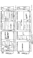
図12は、例示的なTDDフレーム構造を示している。図示のように、DLサブフレームは、プリアンブルで始まり、フレーム制御ヘッダ(FCH:Frame Control Header)、下りリンクMAP(DL-MAP)、及び上りリンクMAP(UL-MAP)が続く。プリアンブルは、MSが同期及びチャネル推定を実行するのに役立つ。FCHは、バーストプロファイル(burst profile)と、現在のFCHの直後にある1つ以上の下りリンクバーストの長さとを指定する。DL-MAP及びUL-MAPは、現在のフレーム内で、それぞれ下りリンク及び上りリンク方向に割り当てられた対応するリソースをMSに通知する。一般的に、BSは、いずれかのデータ領域の形状及び位置を自由に規定できる。BSから受信したスケジュールに基づいて、各MSは、いつ(すなわち、OFDMAシンボル)及びどこで(すなわち、サブチャネル)BSから受信すべきか及びBSに送信すべきかを判定できる。送信モードから受信モードに又はその逆に切り替えるのに十分な時間を無線装置に与えるために、適切な時間ギャップ(すなわち、受信−送信遷移ギャップ(RTG:receive-to-transmit transition gap)及び送信−受信遷移ギャップ(TTG:transmit-to-receive transition gap)(ここではTRGとも呼ばれる)が、連続するサブフレーム間に挿入されなければならない。 FIG. 12 shows an exemplary TDD frame structure. As shown in the figure, a DL subframe starts with a preamble, followed by a frame control header (FCH), a downlink MAP (DL-MAP), and an uplink MAP (UL-MAP). The preamble helps the MS perform synchronization and channel estimation. The FCH specifies a burst profile and the length of one or more downlink bursts immediately following the current FCH. The DL-MAP and UL-MAP notify the MS of the corresponding resources allocated in the downlink and uplink directions, respectively, in the current frame. In general, the BS can freely define the shape and position of any data area. Based on the schedule received from the BS, each MS can determine when (ie, an OFDMA symbol) and where (ie, a subchannel) should be received from and transmitted to the BS. Appropriate time gaps (ie, receive-to-transmit transition gaps (RTGs) and transmit-) are provided to allow the wireless device sufficient time to switch from transmit mode to receive mode or vice versa. A transmit-to-receive transition gap (TTG) (also referred to herein as TRG) must be inserted between consecutive subframes.
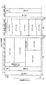
図13は、例示的なFDDフレーム構造を示している。IEEE802.16は、FDDシステムのBSが全二重モードで動作し、MSが全二重(FDD)又は半二重(H-FDD)になることを指定する。図13に示すFDDフレーム構造は、H-FDD及びFDDのMSの同時の動作をサポートする。フレーム構造は、フレームの別個の区画でフレームを共有する2つのグループのH-FDDのMS(グループ1及びグループ2)の協調した送信構成をサポートする。図示のように、DLフレームは、2つのサブフレームを含む。DLサブフレーム1は、プリアンブル領域と、MAP領域(MAP1)と、データ領域(DL1)とを有する。DLサブフレーム2は、MAP領域(MAP2)と、データ領域(DL2)とを有する。同様に、ULフレームは2つのサブフレームUL2及びUL1を含む。図13は、DLサブフレームに対するULサブフレームのタイミング関係を示している。4つのパラメータTTG1、TTG2、RTG1及びRTG2は、H-FDDのMSの送受信切り替え時間にラウンドトリップ伝搬遅延を加えたものに適応するほど十分に大きい。グループ1のH-FDDのMSは、DLサブフレーム1を受信し、上りリンクサブフレームUL1で送信する。グループ2のH-FDDのMSは、DLサブフレーム2を受信し、上りリンクサブフレームUL2で送信する。MAP領域MAP1及びMAP2は無関係であり、FCH、DL-MAP及びUL-MAPを含む。
FIG. 13 shows an exemplary FDD frame structure. IEEE 802.16 specifies that the BS of the FDD system operates in full-duplex mode and that the MS is full-duplex (FDD) or half-duplex (H-FDD). The FDD frame structure shown in FIG. 13 supports simultaneous operation of H-FDD and FDD MS. The frame structure supports a coordinated transmission configuration of two groups of H-FDD MSs (
IEEE802.16jは、IEEE802.16システムにマルチホップ中継(multihop relay)機能を追加する。典型的には、中継に基づくシステムは、低コストの中継局(relay)を有する。中継局は、特定の基地局(BS)に関連付けられる。中継局は、BSのカバレッジ領域を拡張するため及び/又は無線アクセスシステムの容量(キャパシティ)を増加させるために使用され得る。中継局は、中継局の通信範囲内のMSが中継局を通じてBSと通信できるように、BSからの送信/BSへの送信を繰り返すことができる。中継局は、BSとMSとの双方と無線通信するため、バックホールリンクは必要ない。この種類のネットワークは、マルチホップネットワークと呼ばれることがある。この理由は、MSと配線(有線)接続との間に1つより多くの無線接続が存在する可能性があるからである。特定のネットワーク構成に応じて、特定のMSは、1つ以上の周辺の中継局及び/又は1つ以上の周辺のBSを介してネットワークアクセスを取得してもよい。更に、中継局自体は、特定のBSに接続するために1つ以上の利用可能なパスの選択肢を有してもよい。IEEE802.16jは、MSの観点から、中継局(RS:Relay Station)を通じて中継されるマルチホップ中継基地局(MR-BS:Multihop Relay Base Station)とのいずれかの通信が、直接的にBSから来ているのと同じであるかのように見えることを要求する。MR-BS又はRSとMSとの間の無線リンクは、アクセスリンクと呼ばれ、MR-BSとRSとの間のリンク又はRSの対の間のリンクは、中継リンクと呼ばれる。 IEEE 802.16j adds a multihop relay function to the IEEE 802.16 system. Typically, relay-based systems have low cost relays. A relay station is associated with a particular base station (BS). The relay station may be used to expand the coverage area of the BS and / or increase the capacity of the radio access system. The relay station can repeat transmission from the BS / transmission to the BS so that the MS within the communication range of the relay station can communicate with the BS through the relay station. Since the relay station communicates wirelessly with both the BS and the MS, no backhaul link is necessary. This type of network is sometimes referred to as a multi-hop network. This is because there may be more than one wireless connection between the MS and the wired (wired) connection. Depending on the particular network configuration, a particular MS may obtain network access via one or more peripheral relay stations and / or one or more peripheral BSs. Furthermore, the relay station itself may have one or more available path options to connect to a particular BS. IEEE802.16j, from the MS point of view, any communication with a multihop relay base station (MR-BS) relayed through a relay station (RS) is directly transmitted from the BS. Require that it looks the same as it is coming. The radio link between MR-BS or RS and MS is called an access link, and the link between MR-BS and RS or the link between RS pairs is called a relay link.
IEEE802.16jは、2つの異なるRS動作モード(トランスペアレント及び非トランスペアレント)を規定する。トランスペアレントRS(T-RS:Transparent RS)は、プリアンブル、FCH及びMAPのような制御情報を送信しない。T-RSに接続されたMSは、MR-BSから直接的に制御情報を受信し、T-RSはデータトラヒックのみを中継する。非トランスペアレントRS(NT-RS:Non-Transparent RS)は、プリアンブル及び他のブロードキャストメッセージを送信し、同様にデータトラヒックも中継する。 IEEE 802.16j defines two different RS operating modes (transparent and non-transparent). Transparent RS (T-RS) does not transmit control information such as preamble, FCH and MAP. The MS connected to the T-RS receives control information directly from the MR-BS, and the T-RS relays only data traffic. Non-transparent RS (NT-RS) sends preambles and other broadcast messages, as well as relays data traffic.
IEEE802.16jは、図12に示すようなIEEE802.16 TDDフレーム構造のように、DL及びULサブフレームに分割されるTDDフレームを指定する。しかし、IEEE802.16jサブフレームは、BS-MS通信に加えて、BS-RS通信及びRS-MS通信をサポートするためのゾーンに更に分割される。トランスペアレント及び非トランスペアレントモードの双方において、MS/T-RSとのBS/NT-RS通信をサポートする、いわゆる“アクセスゾーン(access zone)”が規定される。トランスペアレントモードでは、いわゆる“トランスペアレントゾーン(transparent zone)”がMSとのT-RS通信のために規定される。非トランスペアレントモードでは、“中継ゾーン(relay zone)”がNT-RSとのBS/NT-RS通信のために規定される。図14は、T-RSフレーム構造の例示的な構成を示している。図15は、MR-BS及びRSが周波数領域でULサブフレームを分けたT-RSフレーム構造の例示的な構成を示している。図16は、NT-RSフレーム構造の最小構成の例を示している。図17は、MR-BS及びRSが周波数領域でULサブフレームを分けたNT-RSフレーム構造の構成例を示している。 IEEE802.16j specifies a TDD frame that is divided into DL and UL subframes, like an IEEE802.16 TDD frame structure as shown in FIG. However, the IEEE 802.16j subframe is further divided into zones for supporting BS-RS communication and RS-MS communication in addition to BS-MS communication. In both transparent and non-transparent modes, so-called “access zones” are defined that support BS / NT-RS communication with MS / T-RS. In the transparent mode, a so-called “transparent zone” is defined for T-RS communication with the MS. In non-transparent mode, a “relay zone” is defined for BS / NT-RS communication with NT-RS. FIG. 14 shows an exemplary configuration of a T-RS frame structure. FIG. 15 shows an exemplary configuration of a T-RS frame structure in which MR-BS and RS divide UL subframes in the frequency domain. FIG. 16 shows an example of the minimum configuration of the NT-RS frame structure. FIG. 17 shows a configuration example of an NT-RS frame structure in which MR-BS and RS divide UL subframes in the frequency domain.
現在では、IEEE802.16j標準のような中継動作のための利用可能な標準は、TDDフレーム構造のみ(従って、TDD動作モードのみ)をサポートしている。しかし、WiMax、IEEE802.16e及びLTEのようなシステムは、FDD、H-FDD及びTDD可能な移動端末をサポートする。 Currently, available standards for relay operation, such as the IEEE 802.16j standard, support only the TDD frame structure (and therefore only the TDD mode of operation). However, systems such as WiMax, IEEE 802.16e and LTE support mobile terminals capable of FDD, H-FDD and TDD.
中継システムのカバレッジ及び他の性能拡張がFDDに基づくシステムに拡張可能なように、マルチホップ中継ネットワークでFDD及びH-FDDをサポートする必要が存在する。 There is a need to support FDD and H-FDD in multi-hop relay networks so that relay system coverage and other performance extensions can be extended to systems based on FDD.
本発明の態様によれば、マルチホップ無線中継ネットワークで中継局を動作させる方法が提供され、中継局は、上位局(superordinate station)及び下位局(subordinate station)と通信する。この方法は、第1のキャリア周波数で上位局から下りリンク送信を受信し、第2のキャリア周波数で下位局から上りリンク送信を受信し、第1のキャリア周波数で下位局に下りリンク送信を送信し、第2のキャリア周波数で上位局に上りリンク送信を送信することを有する。中継局と上位局との間の通信は、フレームを使用してスケジューリングされてもよく、それぞれのフレームは、第1のキャリア周波数の下りリンク部分を有する。下りリンク部分は、上位局と第1の複数の局との間の通信のための第1の下りリンクサブフレームと、上位局と第2の複数の局との間の通信のための第2の下りリンクサブフレームとを有する。それぞれのフレームは、第2のキャリア周波数の上りリンク部分を有する。上りリンク部分は、上位局と第1の複数の局との間の通信のための第1の上りリンクサブフレームと、上位局と第2の複数の局との間の通信のための第2の上りリンクサブフレームとを有する。第1の下りリンクサブフレームは、第1の時間間隔に対応してもよく、第1の上りリンクサブフレームは、第2の時間間隔に対応してもよい。第1の時間間隔及び第2の時間間隔は重ならない。中継局は、第1の複数の局のうち1つでもよく、これにより、下りリンク送信の受信は、第1の下りリンクサブフレームで行われ、上りリンク送信の送信は、第1の上りリンクサブフレームで行われる。 According to an aspect of the present invention, a method for operating a relay station in a multi-hop wireless relay network is provided, wherein the relay station communicates with a superordinate station and a subordinate station. This method receives a downlink transmission from a higher station at a first carrier frequency, receives an uplink transmission from a lower station at a second carrier frequency, and transmits a downlink transmission to a lower station at a first carrier frequency. And transmitting the uplink transmission to the upper station on the second carrier frequency. Communication between the relay station and the upper station may be scheduled using frames, each frame having a downlink portion of the first carrier frequency. The downlink portion includes a first downlink subframe for communication between the upper station and the first plurality of stations, and a second for communication between the upper station and the second plurality of stations. Downlink subframes. Each frame has an uplink portion of the second carrier frequency. The uplink portion includes a first uplink subframe for communication between the upper station and the first plurality of stations, and a second for communication between the upper station and the second plurality of stations. Uplink subframes. The first downlink subframe may correspond to a first time interval, and the first uplink subframe may correspond to a second time interval. The first time interval and the second time interval do not overlap. The relay station may be one of the first plurality of stations, whereby reception of downlink transmission is performed in the first downlink subframe, and transmission of uplink transmission is performed in the first uplink. Done in subframes.
本発明の更なる態様によれば、上位局及び下位局と通信する中継局を有するマルチホップ中継システムが提供される。中継局は、第1のキャリア周波数で上位局から下りリンク送信を受信し、第2のキャリア周波数で下位局から上りリンク送信を受信する受信回路と、第1のキャリア周波数で下位局に下りリンク送信を送信し、第2のキャリア周波数で上位局に上りリンク送信を送信する送信回路とを有する。中継局と上位局との間の通信は、フレームを使用してスケジューリングされてもよく、それぞれのフレームは、第1のキャリア周波数の下りリンク部分を有する。下りリンク部分は、上位局と第1の複数の局との間の通信のための第1の下りリンクサブフレームと、上位局と第2の複数の局との間の通信のための第2の下りリンクサブフレームとを有する。それぞれのフレームは、第2のキャリア周波数の上りリンク部分を有する。上りリンク部分は、上位局と第1の複数の局との間の通信のための第1の上りリンクサブフレームと、上位局と第2の複数の局との間の通信のための第2の上りリンクサブフレームとを有する。第1の下りリンクサブフレームは、第1の時間間隔に対応してもよく、第1の上りリンクサブフレームは、第2の時間間隔に対応してもよい。第1の時間間隔及び第2の時間間隔は重ならない。中継局は、第1の複数の局のうち1つでもよく、これにより、下りリンク送信の受信は、第1の下りリンクサブフレームで行われ、上りリンク送信の送信は、第1の上りリンクサブフレームで行われる。 According to a further aspect of the present invention, there is provided a multi-hop relay system having a relay station that communicates with an upper station and a lower station. The relay station receives a downlink transmission from the upper station at the first carrier frequency and receives an uplink transmission from the lower station at the second carrier frequency, and downlinks to the lower station at the first carrier frequency. A transmission circuit that transmits the transmission and transmits the uplink transmission to the upper station on the second carrier frequency. Communication between the relay station and the upper station may be scheduled using frames, each frame having a downlink portion of the first carrier frequency. The downlink portion includes a first downlink subframe for communication between the upper station and the first plurality of stations, and a second for communication between the upper station and the second plurality of stations. Downlink subframes. Each frame has an uplink portion of the second carrier frequency. The uplink portion includes a first uplink subframe for communication between the upper station and the first plurality of stations, and a second for communication between the upper station and the second plurality of stations. Uplink subframes. The first downlink subframe may correspond to a first time interval, and the first uplink subframe may correspond to a second time interval. The first time interval and the second time interval do not overlap. The relay station may be one of the first plurality of stations, whereby reception of downlink transmission is performed in the first downlink subframe, and transmission of uplink transmission is performed in the first uplink. Done in subframes.
本発明の他の態様及び特徴は、添付図面と共に本発明の特定の実施例の以下の説明を読むことにより、当業者に明らかになる。 Other aspects and features of the present invention will become apparent to those of ordinary skill in the art by reading the following description of specific embodiments of the invention in conjunction with the accompanying drawings.
図面に、本発明の実施例を単なる例として示す。 In the drawings, embodiments of the invention are shown by way of example only.
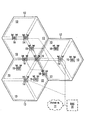
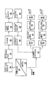
次に図面を参照する。同様の参照符号は、同様の要素を示す。図1は、複数のセル12内での無線通信を制御する基地局コントローラ(BSC:base station controller)10を示しており、複数のセルは、対応する基地局(BS:base station)14によりサービス提供される。或る構成では、各セルは、複数のセクタ13(図示せず)に更に分割される。一般的に、各基地局14は、移動端末16とのOFDMを使用した通信を容易にする。移動端末16は、対応する基地局14に関連するセル12内にある。基地局14に対する移動端末16の移動は、チャネル状態におけるかなりの変動を生じる。図示のように、基地局14及び移動端末16は、通信のための空間ダイバーシチを提供するために、複数のアンテナを含んでもよい。以下に詳細に説明するように、中継局(relay station)15は、基地局14と移動端末16との間の通信を支援してもよい。移動端末16は、いずれかのセル12、セクタ13(図示せず)、基地局14又は中継局15から他のセル12、セクタ13(図示せず)、基地局14又は中継局15にハンドオフされてもよい18。或る構成では、基地局14は、バックホールネットワーク11で各ネットワーク及び他のネットワーク(コアネットワーク又はインターネット(双方とも図示せず)等)と通信する。或る構成では、基地局コントローラ10は必要ない。
Reference is now made to the drawings. Like reference numbers indicate like elements. FIG. 1 shows a base station controller (BSC) 10 that controls radio communication in a plurality of
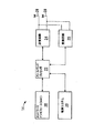
図2は、基地局14の例を示している。基地局14は、一般的に、制御システム20と、ベースバンドプロセッサ22と、送信回路24と、受信回路26と、アンテナ28と、ネットワークインタフェース30とを含む。受信回路26は、移動端末16(図3に図示する)及び中継局15(図4に図示する)により提供された1つ以上の遠隔送信機から、情報を運ぶ無線周波数信号を受信する。低雑音増幅器及びフィルタ(図示せず)は、処理のために信号からブロードバンド干渉を増幅及び除去するように協調してもよい。ダウンコンバージョン及びデジタル化回路(図示せず)は、フィルタリングされた受信信号を中間又はベースバンド周波数信号にダウンコンバートする。中間又はベースバンド周波数信号は、1つ以上のデジタルストリームにデジタル化される。
FIG. 2 shows an example of the
ベースバンドプロセッサ22は、デジタル化された受信信号を処理し、受信信号で伝達された情報又はデータビットを抽出する。典型的には、この処理は、復調、復号化及び誤り訂正動作を有する。従って、ベースバンドプロセッサ22は、一般的には、1つ以上のデジタルシグナルプロセッサ(DSP:digital signal processor)又は特定用途向け集積回路(ASIC:application-specific integrated circuit)に実装される。受信情報は、ネットワークインタフェース30を介して無線ネットワークを通じて送信される、或いは、直接的に又は中継局15の支援により、基地局14によりサービス提供される他の移動端末16に送信される。
The
送信側では、ベースバンドプロセッサ22は、制御システム20の制御で、ネットワークインタフェース30からデジタル化されたデータ(音声、データ又は制御情報を表してもよい)を受信し、送信のためにデータを符号化する。符号化されたデータは、送信回路24に出力され、そこで、所望の送信周波数を有する1つ以上のキャリア信号により変調される。電力増幅器(図示せず)は、変調されたキャリア信号を送信に適したレベルに増幅し、マッチングネットワーク(matching network)(図示せず)を通じて変調されたキャリア信号をアンテナ28に配信する。変調及び処理の詳細は、以下に詳細に説明する。
On the transmitting side, the
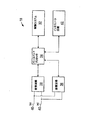
図3は、移動端末16の例を示している。基地局14と同様に、移動端末16は、制御システム32と、ベースバンドプロセッサ34と、送信回路36と、受信回路38と、アンテナ40と、ユーザインタフェース回路42とを含む。受信回路38は、1つ以上の基地局14及び中継局15から情報を運ぶ無線周波数信号を受信する。低雑音増幅器及びフィルタ(図示せず)は、処理のために信号からブロードバンド干渉を増幅及び除去するように協調してもよい。ダウンコンバージョン及びデジタル化回路(図示せず)は、フィルタリングされた受信信号を中間又はベースバンド周波数信号にダウンコンバートする。中間又はベースバンド周波数信号は、1つ以上のデジタルストリームにデジタル化される。
FIG. 3 shows an example of the
ベースバンドプロセッサ34は、デジタル化された受信信号を処理し、受信信号で伝達された情報又はデータビットを抽出する。典型的には、この処理は、復調、復号化及び誤り訂正動作を有する。ベースバンドプロセッサ34は、一般的には、1つ以上のデジタルシグナルプロセッサ(DSP:digital signal processor)又は特定用途向け集積回路(ASIC:application-specific integrated circuit)に実装される。
The
送信について、ベースバンドプロセッサ34は、制御システム32からデジタル化されたデータ(音声、ビデオ、データ又は制御情報を表してもよい)を受信し、送信のためにデータを符号化する。符号化されたデータは、送信回路36に出力され、そこで、所望の送信周波数にある1つ以上のキャリア信号を変調するために変調器により変調される。電力増幅器(図示せず)は、変調されたキャリア信号を送信に適したレベルに増幅し、マッチングネットワーク(図示せず)を通じて変調されたキャリア信号をアンテナ40に配信する。当業者に利用可能な様々な変調及び処理技術が、直接的に又は中継局を介して移動端末と基地局との間で信号を送信するために使用される。
For transmission, the
OFDM変調では、送信帯域は複数の直交搬送波に分割される。各搬送波は、送信されるデジタルデータに従って変調される。OFDMは送信帯域を複数のキャリアに分割するため、キャリア毎の帯域幅は減少し、キャリア毎の変調時間は増加する。複数のキャリアが並列して送信されるため、いずれかの所与のキャリアのデジタルデータ若しくはシンボルの送信レートは、単一のキャリアが使用される場合より低い。 In OFDM modulation, the transmission band is divided into a plurality of orthogonal carriers. Each carrier wave is modulated according to the transmitted digital data. Since OFDM divides the transmission band into a plurality of carriers, the bandwidth for each carrier decreases and the modulation time for each carrier increases. Since multiple carriers are transmitted in parallel, the transmission rate of digital data or symbols for any given carrier is lower than when a single carrier is used.
OFDM変調は、送信される情報について逆高速フーリエ変換(IFFT:Inverse Fast Fourier Transform)の性能を利用する。復調について、受信信号での高速フーリエ変換(FFT:Fast Fourier Transform)の性能は、送信された情報を回復する。実際に、IFFT及びFFTは、それぞれ逆離散フーリエ変換(IDFT:Inverse Discrete Fourier Transform)及び離散フーリエ変換(DFT:Discrete Fourier Transform)を実行するデジタル信号処理により提供される。従って、OFDM変調の特徴は、送信チャネル内の複数の帯域について直交搬送波が生成される点にある。変調された信号は、比較的低い送信レートを有し、各帯域内に留まることができるデジタル信号である。個々の搬送波は、デジタル信号により直接的に変調されない。その代わりに、全ての搬送波は、IFFT処理により同時に変調される。 OFDM modulation utilizes the performance of Inverse Fast Fourier Transform (IFFT) for transmitted information. For demodulation, the performance of Fast Fourier Transform (FFT) on the received signal recovers the transmitted information. Actually, IFFT and FFT are provided by digital signal processing that performs Inverse Discrete Fourier Transform (IDFT) and Discrete Fourier Transform (DFT), respectively. Therefore, the characteristic of OFDM modulation is that orthogonal carriers are generated for a plurality of bands in the transmission channel. The modulated signal is a digital signal that has a relatively low transmission rate and can remain within each band. Individual carriers are not directly modulated by digital signals. Instead, all carriers are modulated simultaneously by IFFT processing.
一実施例では、OFDMは、基地局14から移動端末16への下りリンク送信に少なくとも使用されることが好ましい。各基地局14は、“n”個の送信アンテナ28(n>=1)を備えており、各移動端末16は、“m”個の受信アンテナ40(m>=1)を備えている。特に、各アンテナは、適切なデュプレクサ又はスイッチを使用して受信及び送信に使用可能であり、簡潔にするためにのみこのようにラベルが付与されている。
In one embodiment, OFDM is preferably used at least for downlink transmission from the
中継局15が使用される場合、OFDMは、基地局14から中継局15への下りリンク送信と、中継局15から移動端末16への下りリンク送信とに使用されることが好ましい。
When
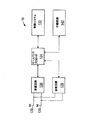
図4は、例示的な中継局15を示している。基地局14及び移動端末16と同様に、中継局15は、制御システム132と、ベースバンドプロセッサ134と、送信回路136と、受信回路138と、アンテナ130と、中継回路142とを含む。中継回路142は、中継局14が基地局16と移動端末16との間の通信を支援することを可能にする。受信回路138は、1つ以上の基地局14及び無線端末16から情報を運ぶ無線周波数信号を受信する。低雑音増幅器及びフィルタ(図示せず)は、処理のために信号からブロードバンド干渉を増幅及び除去するように協調してもよい。ダウンコンバージョン及びデジタル化回路(図示せず)は、フィルタリングされた受信信号を中間又はベースバンド周波数信号にダウンコンバートする。中間又はベースバンド周波数信号は、1つ以上のデジタルストリームにデジタル化される。
FIG. 4 shows an
ベースバンドプロセッサ134は、デジタル化された受信信号を処理し、受信信号で伝達された情報又はデータビットを抽出する。典型的には、この処理は、復調、復号化及び誤り訂正動作を有する。ベースバンドプロセッサ134は、一般的には、1つ以上のデジタルシグナルプロセッサ(DSP:digital signal processor)又は特定用途向け集積回路(ASIC:application-specific integrated circuit)に実装される。
The
送信について、ベースバンドプロセッサ134は、制御システム132からデジタル化されたデータ(音声、ビデオ、データ又は制御情報を表してもよい)を受信し、送信のためにデータを符号化する。符号化されたデータは、送信回路136に出力され、そこで、所望の送信周波数にある1つ以上のキャリア信号を変調するために変調器により変調される。電力増幅器(図示せず)は、変調されたキャリア信号を送信に適したレベルに増幅し、マッチングネットワーク(図示せず)を通じて変調されたキャリア信号をアンテナ130に配信する。前述のように、当業者に利用可能な様々な変調及び処理技術が、直接的に又は中継局を介して間接的に移動端末と基地局との間で信号を送信するために使用される。
For transmission, the
図5を参照して、論理OFDM送信アーキテクチャについて説明する。まず、基地局コントローラ10は、直接的に又は中継局15の支援により、様々な移動端末16に送信されるデータを基地局14に送信する。基地局14は、送信用のデータをスケジューリングするため及びスケジューリングされたデータを送信するための適切な符号化及び変調技術を選択するために、移動端末に関連するチャネル品質インジケータ(CQI:channel quality indicator)を使用してもよい。CQIは、移動端末16からの直接のものでもよく、移動端末16により提供された情報に基づいて基地局14で決定されてもよい。いずれの場合でも、各移動端末16のCQIは、チャネル振幅(又は応答)がOFDM周波数帯域を通じて変化する程度の関数である。
With reference to FIG. 5, a logical OFDM transmission architecture will be described. First, the
ビットのストリームであるスケジューリングされたデータ44は、データスクランブル化ロジック46を使用してデータに関連するピーク対平均電力比を低減するようにスクランブル化される。スクランブル化されたデータの巡回冗長検査(CRC:cyclic redundancy check)は、CRC付加ロジック48を使用して決定され、スクランブル化されたデータに付与されてもよい。次に、チャネル符号化ロジック50を使用して、チャネル符号化が実行され、移動端末16での回復及び誤り訂正を容易にするためにデータに冗長性を効果的に付加する。この場合も同様に、特定の移動端末16のチャネル符号化は、CQIに基づく。或る実装では、チャネル符号化ロジック50は、既知のTurbo符号化技術を使用する。符号化されたデータは、符号化に関連するデータ展開を補うために、レートマッチング(rate matching)ロジック52により処理される。
The scheduled
ビットインターリーバロジック54は、符号化されたデータのビットを体系的に並び替え、連続的なデータビットのロスを最小化する。結果のデータビットは、マッピングロジック56により選択されたベースバンド変調に応じて対応するシンボルに体系的にマッピングされる。直交振幅変調(QAM:Quadrature Amplitude Modulation)、四相位相シフトキーイング(QPSK:Quadrature Phase Shift Key)が使用されることが好ましい。変調の程度は、特定の移動端末のCQIに基づいて選択されることが好ましい。シンボルは、シンボルインターリーバロジック58を使用して、周波数選択性フェージングにより生じる周期的なデータロスに対する送信信号の耐性を更に増強するために体系的に並び替えられてもよい。
The bit
この時点で、ビットのグループは、振幅及び位相コンステレーションの位置を表すシンボルにマッピングされる。空間ダイバーシチが望まれる場合、シンボルのブロックは、時空ブロック符号(STC:space-time block code)符号化ロジック60により処理される。STC符号化ロジック60は、送信信号を干渉に対してより耐性のあるようにし、移動端末16で容易に復号されるように、シンボルを変更する。STC符号化ロジック60は、入来するシンボルを処理し、基地局14の送信アンテナ28の数に対応する“n”個の出力を提供する。図5に関して前述した制御システム20及び/又はベースバンドプロセッサ22は、STC符号化を制御するためにマッピング制御信号を提供する。この時点で、“n”個の出力のシンボルが、送信されて移動端末16により回復可能なデータを表すことを仮定する。
At this point, the group of bits is mapped to a symbol representing the position of the amplitude and phase constellation. If space diversity is desired, the block of symbols is processed by a space-time block code (STC)
この例では、基地局14が2つのアンテナ28(n=2)を有しており、STC符号化ロジック60がシンボルの2つの出力ストリームを提供することを仮定する。従って、STC符号化ロジック60により出力される各シンボルストリームは、理解を容易にするために別々に図示されている対応するIFFTプロセッサ62に送信される。当業者は、このようなデジタル信号処理を提供するために、1つ以上のプロセッサが単独で又はここに記載の他の処理と組み合わせて使用されてもよいことを認識する。IFFTプロセッサ62は、逆フーリエ変換を提供するために各シンボルで動作することが好ましい。IFFTプロセッサ62の出力は、時間領域でのシンボルを提供する。時間領域のシンボルはフレームにグループ化され、フレームは、プレフィックス挿入ロジック64によりプレフィックスに関連付けられる。結果の信号のそれぞれは、デジタル領域で中間周波数にアップコンバートされ、対応するデジタルアップコンバート(DUC:digital up-conversion)及びデジタル・アナログ(D/A)変換回路66を介してアナログ信号に変換される。結果の(アナログ)信号は、所望のRF周波数で同時に変調され、増幅され、RF回路68及びアンテナ28を介して送信される。特に、目的の移動端末16により知られているパイロット信号は、サブキャリア間に分散される。以下に詳細に説明する移動端末16は、チャネル推定のためにパイロット信号を使用してもよい。
In this example, assume that the
基地局14から直接的な又は中継局15の支援による移動端末16による送信信号の受信を示す図6に参照が行われる。移動端末16の各アンテナ40に送信信号が到達すると、各信号は、対応するRF回路70により復調及び増幅される。簡潔且つ明瞭にするために、2つの受信パスのうち1つのみを詳細に説明及び図示する。アナログ・デジタル(A/D)変換器及びダウンコンバート回路72は、デジタル処理のために、アナログ信号をデジタル化してダウンコンバートする。結果のデジタル化された信号は、受信信号レベルに基づいてRF回路70の増幅器の利得を制御するために、自動利得制御回路(AGC:automatic gain control)74により使用されてもよい。
Reference is made to FIG. 6 showing reception of transmission signals by the
まず、デジタル化された信号は、同期ロジック76に提供される。同期ロジック76は、複数のOFDMシンボルをバッファに入れて、2つの連続するOFDMシンボルの間の自己相関を計算する粗い同期ロジック78を含む。相関結果の最大値に対応する結果の時間インデックスは、ヘッダに基づいて正確なフレーム開始位置を決定するために細かい同期ロジック80により使用される細かい同期検索ウィンドウを決定する。細かい同期ロジック80の出力は、フレーム整列ロジック84によるフレーム取得を容易にする。適切なフレーム整列は、次のFFT処理が時間領域から周波数領域への正確な変換を提供するために重要である。細かい同期アルゴリズムは、ヘッダにより伝達される受信パイロット信号と既知のパイロットデータのローカルコピーとの間の相関に基づく。フレーム整列の取得が生じると、OFDMシンボルのプレフィックスは、プレフィックス除去ロジック86で除去され、結果のサンプルは、周波数オフセット訂正ロジック88に送信される。周波数オフセット訂正ロジック88は、送信機及び受信機の一致しないローカル発振器により生じたシステム周波数オフセットを補う。同期ロジック76は、周波数オフセット及びクロック推定ロジック82を含むことが好ましい。周波数オフセット及びクロック推定ロジック82は、ヘッダに基づき、送信信号でのこのような効果を推定し、適切にOFDMシンボルを処理するためにこれらの推定を訂正ロジック88に提供することに役立てる。
First, the digitized signal is provided to
この時点で、時間領域のOFDMシンボルは、FFT処理ロジック90を使用して周波数領域に変換する準備ができている。結果は周波数領域のシンボルであり、周波数領域のシンボルは、処理ロジック92に送信される。処理ロジック92は、分散パイロット抽出ロジック94を使用して分散したパイロット信号を抽出し、チャネル推定ロジック96を使用して抽出されたパイロット信号に基づいてチャネル推定を決定し、チャネル再構成ロジック98を使用して全てのサブキャリアについてチャネル応答を提供する。サブキャリア毎のチャネル応答を決定するために、基本的には、パイロット信号は、時間及び周波数の双方において既知のパターンでOFDMサブキャリアを通じてデータシンボル間に分散した複数のパイロットシンボルである。図6を参照し続けると、処理ロジックは、特定の時間の特定のサブキャリアで想定されるパイロットシンボルと受信したパイロットシンボルとを比較し、パイロットシンボルが送信されたサブキャリアのチャネル応答を決定する。結果は、パイロットシンボルが提供されない残りのサブキャリアの全てではなくてもほとんどのチャネル応答を推定するように補間される。実際に補間されたチャネル応答は、OFDMチャネルのサブキャリアの全てではなくてもほとんどのチャネル応答を含む全体のチャネル応答を推定するために使用される。
At this point, the time-domain OFDM symbols are ready to be converted to the frequency domain using the
各受信パスのチャネル応答から導かれる周波数領域のシンボル及びチャネル再構成情報は、STC復号化器100に提供される。STC復号化器100は、双方の受信パスでSTC復号化を提供し、送信シンボルを回復する。チャネル再構成情報は、各周波数領域のシンボルを処理するときに送信チャネルの効果を除去するのに十分な等化情報をSTC復号化器100に提供する。中継局は、本発明に関して他の基地局又は端末として動作してもよい。
Frequency domain symbols and channel reconfiguration information derived from the channel response of each receive path are provided to the
回復されたシンボルは、シンボルデインターリーバロジック102を使用して逆の順序に配置される。シンボルデインターリーバロジック102は、送信機のシンボルインターリーバロジック58に対応する。デインターリーブされたシンボルは、デマッピングロジック104を使用して、対応するビットストリームに復調又はデマッピングされる。ビットは、ビットデインターリーバロジック106を使用してデインターリーブされる。ビットデインターリーバロジック106は、送信アーキテクチャのビットインターリーバロジック54に対応する。デインターリーブされたビットは、レートデマッチングロジック108により処理され、最初にスクランブル化されたデータ及びCRCチェックサムを回復するためにチャネル復号化ロジック110に提示される。従って、CRCロジック112は、CRCチェックサムを除去し、通常の方法でスクランブル化されたデータを検査し、既知の基地局のデスクランブル化符号を使用してデスクランブル化するためにこれをデスクランブル化ロジック114に提供し、元々送信されたデータ116を回復する。
The recovered symbols are placed in reverse order using
データ116の回復と並行して、CQI又は少なくとも基地局14でCQIを生成するのに十分な情報が決定され、基地局14に送信される。前述のように、CQIは、搬送波対干渉比(CIR:carrier-to-interference ratio)と、チャネル応答がOFDM周波数帯域の様々なサブキャリアを通じて変化する程度との関数でもよい。この実施例では、情報を送信するために使用されるOFDM周波数帯域の各サブキャリアのチャネル利得は、チャネル利得がOFDM周波数帯域を通じて変化する程度を決定するために、相互に比較されてもよい。変動の程度を測定するために複数の技術が利用可能であるが、1つの技術は、データを送信するために使用されているOFDM周波数帯域を通じた各サブキャリアのチャネル利得の標準偏差を計算することである。
In parallel with the recovery of
図1〜6は、本発明の実施例を実装するために使用され得る通信システムの1つの特定の例を提供している。実施例は、特定の例とは異なるアーキテクチャを有するが、ここに記載の実施例の実装に従った方法で動作する通信システムで実装されてもよいことが分かる。 1-6 provide one specific example of a communication system that can be used to implement an embodiment of the present invention. Although the embodiments have a different architecture than the specific examples, it will be appreciated that the embodiments may be implemented in a communication system that operates in a manner consistent with the implementation of the embodiments described herein.
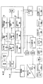
図7は、本発明の或る実施例を実装するために使用され得る全体ネットワークアーキテクチャ700の論理表現を示すブロック図である。図示のように、全体ネットワークアーキテクチャ700は、移動局(MS)702と、基地局(BS)704及びASNゲートウェイ(ASN-GW:access service network gateway)705を有するアクセスサービスネットワーク(ASN:access service network)706と、複数の接続サービスネットワーク(CSN:connectivity service network)708とを有する。ネットワークアーキテクチャ700は、WiMAXネットワークアーキテクチャ(全内容を引用するWiMAX Forum Network Architecture Stage 2-3: Release 1, Version 1.2)に規定されたフレームワークに基づいてもよい。
FIG. 7 is a block diagram illustrating a logical representation of an overall network architecture 700 that may be used to implement certain embodiments of the present invention. As shown, an overall network architecture 700 includes a mobile station (MS) 702, a base station (BS) 704, and an access service network (ASN) 705 having an ASN gateway (ASN-GW: access service network gateway) 705. ) 706 and a plurality of connectivity service networks (CSN) 708. The network architecture 700 may be based on the framework defined in the WiMAX network architecture (WiMAX Forum Network Architecture Stage 2-3:
ASN706は、IEEE802m/3準拠のものでもよい。ASN706は、IEEE802.16e/m加入者に無線アクセスを提供するために必要な完全な一式のネットワーク機能を提供してもよい。ASN706は、少なくとも、IEEE802.16e/m MSとのIEEE802.16e/mレイヤ1(L1)及びレイヤ2(L2)接続と、加入者セッションの認証、許可及びセッション課金のためのIEEE802.16e/m加入者のホームネットワークサービスプロバイダ(H-NSP:Home Network Service Provider)へのAAAメッセージの伝送と、IEEE802.16e/m加入者の好みのNSPのネットワーク発見及び選択と、IEEE802.16e/m MSとのレイヤ3(L3)接続を確立するための中継機能(すなわち、IPアドレス割り当て)と、無線リソース管理との機能を提供する。 The ASN 706 may be compliant with IEEE802m / 3. ASN 706 may provide a complete set of network functions necessary to provide wireless access to IEEE 802.16e / m subscribers. The ASN 706 has at least IEEE 802.16e / m Layer 1 (L1) and Layer 2 (L2) connections with IEEE 802.16e / m MS, and IEEE 802.16e / m for subscriber session authentication, authorization and session charging. Transmission of AAA messages to the subscriber's home network service provider (H-NSP), network discovery and selection of the preferred NSP of the IEEE 802.16e / m subscriber, and IEEE 802.16e / m MS A relay function (that is, IP address allocation) for establishing a Layer 3 (L3) connection and a function of radio resource management are provided.
前述の機能に加えて、ポータブル及び移動環境では、ASN706は、ASNに留まるモビリティ(ASN anchored mobility)と、CSNに留まるモビリティ(CSN anchored mobility)と、ページングと、ASN-CSNトンネリングとの機能を更にサポートしてもよい。 In addition to the functions described above, in portable and mobile environments, ASN 706 further increases the functionality of ASN anchored mobility, CSN anchored mobility, paging, and ASN-CSN tunneling. May be supported.
各CSN708は、IEEE802.16e/m加入者にIP接続サービスを提供する一式のネットワーク機能である。所与のASN706は、1つより多くのCSN708により共有されてもよい。CSN708は、ユーザセッションのためのMS IPアドレス及びエンドポイントパラメータの割り当てと、インターネットアクセスと、AAAプロキシ又はサーバと、ユーザ加入者プロファイルに基づくポリシー及び許可制御と、ASN-CSNトンネリングのサポートと、IEEE802.16e/m加入者の課金及びオペレータ間の決済と、ローミング用のCSN間のトンネリングと、ASN間のモビリティとの機能を提供してもよい。CSN708は、ルータ、AAAプロキシ/サーバ、ユーザデータベース、及び相互接続ゲートウェイMSのようなネットワークエレメント(図示せず)を更に有してもよい。 Each CSN 708 is a set of network functions that provide IP connection services to IEEE 802.16e / m subscribers. A given ASN 706 may be shared by more than one CSN 708. CSN 708 is the assignment of MS IP address and endpoint parameters for user sessions, Internet access, AAA proxy or server, policy and admission control based on user subscriber profile, support for ASN-CSN tunneling, IEEE802. Functions such as .16e / m subscriber charging and settlement between operators, tunneling between CSNs for roaming, and mobility between ASNs may be provided. CSN 708 may further include network elements (not shown) such as routers, AAA proxies / servers, user databases, and interconnection gateways MS.
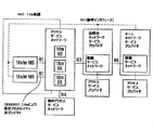
図8を参照すると、中継局(RS)15は、改善されたカバレッジ及び/又はキャパシティを提供するためにネットワークに配置されてもよい。RS802が存在する場合、BS704とMS702との間の通信は、直接行われてもよく、RS802を介して行われてもよい。 Referring to FIG. 8, a relay station (RS) 15 may be located in the network to provide improved coverage and / or capacity. If RS802 is present, communication between BS 704 and MS 702 may occur directly or via RS 802.
IEEE802.16jは、中継する間にサポート可能なキャリアの数に従って2つの中継局の種類を規定する。 IEEE 802.16j defines two types of relay stations according to the number of carriers that can be supported while relaying.
(1)単一無線の中継局:下りリンク及び上りリンク送信にMR-BSのDL/ULキャリアと同じキャリア周波数を使用する中継局である。例えば、MR-BSは間隔T1に周波数f1でRSに送信し、RSは間隔T2にf1で信号をその下位局に転送する。T1及びT2は重複する期間を有さない。 (1) Single radio relay station: A relay station that uses the same carrier frequency as the DL / UL carrier of MR-BS for downlink and uplink transmission. For example, MR-BS transmits to RS at frequency f1 at interval T1, and RS transfers the signal to its subordinate station at interval T2 at f1. T1 and T2 do not have overlapping periods.
(2)デュアル無線の中継局:下りリンク及び上りリンク送信にMR-BSのDL/ULキャリアと異なる周波数を使用する中継局である。例えば、MR-BSは周波数f1でRSに送信し、RSはf2で信号をその下位局に転送する。 (2) Dual radio relay station: A relay station that uses a different frequency from the DL / UL carrier of MR-BS for downlink and uplink transmission. For example, the MR-BS transmits to the RS at the frequency f1, and the RS transfers the signal to its lower stations at f2.
前述の定義はTDD動作を仮定している点に留意すべきである。すなわち、同じ周波数が、いずれかの所与のインタフェースでDL及びUL通信の双方に使用されている。 It should be noted that the above definition assumes TDD operation. That is, the same frequency is used for both DL and UL communications at any given interface.
前述のように、FDDでは、UL及びDLトラヒックは、異なるキャリア周波数で送信される。本発明の実施例によれば、FDD動作では、RSはその下位局がそのDLに使用するものと同じキャリアf1をDL送信に使用してもよく、その下位局がそのULに使用するものと同じキャリアf2をUL送信に使用してもよい。この選択肢は、2つのキャリア周波数を必要とし、以下に詳細に説明するように、フレーム構造は、アクセスゾーンと中継ゾーンとに分割される必要があり得る。図9は、中継局が半二重であり(すなわち、所与のインタフェースで同時に受信及び送信しない)、中継局の動作が時分割方式で行われる場合を示している。図10は、中継局が全二重である(すなわち、同じインタフェースで同時に受信及び送信する)場合を示している。 As described above, in FDD, UL and DL traffic are transmitted on different carrier frequencies. According to an embodiment of the present invention, in FDD operation, the RS may use the same carrier f1 for its DL transmission that its lower station uses for its DL, and its lower station uses it for its UL. The same carrier f2 may be used for UL transmission. This option requires two carrier frequencies, and as described in detail below, the frame structure may need to be divided into an access zone and a relay zone. FIG. 9 shows a case where the relay station is half duplex (ie, does not receive and transmit simultaneously on a given interface) and the operation of the relay station is performed in a time division manner. FIG. 10 shows the case where the relay station is full duplex (ie, receiving and transmitting simultaneously on the same interface).
或いは、FDD動作では、RSは、その上位局のDL(UL)周波数と異なるDL(UL)周波数を使用してもよい。この選択肢は、4つのキャリア(奇数ホップのために2つ及び偶数ホップのために2つ)を必要とする点に留意すべきである。図11はこの場合を示している。 Alternatively, in the FDD operation, the RS may use a DL (UL) frequency that is different from the DL (UL) frequency of the upper station. Note that this option requires 4 carriers (2 for odd hops and 2 for even hops). FIG. 11 shows this case.
図10及び11に示す場合は、図10に従って動作し得る中継局が同じ時間に周波数で同時に受信及び送信するための複雑なアンテナ配置及び干渉除去回路を必要とし得る点を除いて、相互に類似する。構成の観点からは、これらは同じものとして扱われてもよい。 The cases shown in FIGS. 10 and 11 are similar to each other except that relay stations that can operate according to FIG. 10 may require complex antenna arrangements and interference cancellation circuits to simultaneously receive and transmit at the same time in frequency. To do. From a configuration point of view, these may be treated the same.
図9に示す中継システムは、ハードウェア実装及び設計に関して実用的であり、更に、この動作は、IEEE802.16e/Rev2標準で既に規定されているH-FDD動作にうまく適合する。例えば、IEEE802.16e/Rev2/D6に規定されたH-FDDフレーム構造によれば、DL及びULフレームの双方は、2つの間隔T1及びT2に分割される。1つはグループ1のMS/SSのものであり、1つはグループ2のMS/SSのものである。T1(T2)の間隔の間に、グループ1(グループ2)のMS/SSは、BSからDL信号を受信し、T2(T1)の間隔の間に、グループ1(グループ2)のMS/SSは、UL信号をBSに送信する。以下に詳細に説明するように、このフレーム構造は、例えば、任意選択の中継アンブル(R-amble:relay amble)の挿入、FCH/DL-MAPのR-FCH/R-MAPへの置換等により、マルチホップ中継ネットワークで使用されるために変更されてもよい。更に、FDDマルチホップ中継ネットワークをサポートするために1つより多くの中継ゾーンが単一のフレームに現れることが許可された単一フレームの手法を求めることが望ましい。そうでなければ、1つのみの中継ゾーンが単一のフレームに現れることが許可された場合、複数の中継局のために複数のフレームが必要になる。
The relay system shown in FIG. 9 is practical in terms of hardware implementation and design, and this operation fits well with the H-FDD operation already defined in the IEEE 802.16e / Rev2 standard. For example, according to the H-FDD frame structure defined in IEEE 802.16e / Rev2 / D6, both DL and UL frames are divided into two intervals T1 and T2. One is for
<IEEE802.16e/Rev2での既存のFDD及びH-FDDモードの動作>
IEEE802.16e/Rev2で指定されているように、フレーム構成に関するパラメータは、DLチャネル記述子(DCD:DL Channel Descriptor)と、ULチャネル記述子(UCD:UL Channel Descriptor)と、DL-MAPとで伝達される。ネットワーク登録の間に、MSは、まず利用可能なチャネルに同期し、DCD/UCDを受信するためにDL-MAP1(図13)を読み取る。まず、MSは、グループ1の一部としてレンジング(ranging)動作を実行する。1つ又は2つのDCD/UCDが存在してもよい。1つのDCD/UCDが存在し、同じ種類/長さ/値(TLV:type/length/value)が2回繰り返される場合、最初のものはユーザグループ1に属し、次のものはユーザグループ2に属する。
<Operation of existing FDD and H-FDD modes in IEEE802.16e / Rev2>
As specified in IEEE802.16e / Rev2, parameters related to frame configuration are DL channel descriptor (DCD: DL Channel Descriptor), UL channel descriptor (UCD: UL Channel Descriptor), and DL-MAP. Communicated. During network registration, the MS first synchronizes to an available channel and reads DL-MAP1 (FIG. 13) to receive DCD / UCD. First, the MS performs a ranging operation as part of
MSは、DL-MAP1(DL-MAP2)から現在(次)のフレームのT1(T2)の間隔の長さを受信し、UCDからULキャリア周波数を受信する。MS/SSがフレーム内でDL及びUL間隔を正確に見つけることができるように、DCD/UCDは、DLギャップ(DL_gap)サイズ、DL残り(DL_residue)サイズ及びその位置、TTG及びRTG等のようなパラメータを提供する。 The MS receives the length of the interval of T1 (T2) of the current (next) frame from DL-MAP1 (DL-MAP2), and receives the UL carrier frequency from UCD. DCD / UCD is such as DL gap (DL_gap) size, DL residual (DL_residue) size and its position, TTG and RTG etc. so that MS / SS can find DL and UL interval accurately in the frame Provide parameters.
MSは、グループ1を仮定して初期のレンジングを実行する。BSは、H-FDDグループ切り替え情報要素(IE:information element)を送信することにより、いつでもMSユーザグループを切り替えてもよい。グループ切り替えIEがフレームnで受信された場合、フレームn+切り替え遅延+mで有効になる。ただし、切り替え遅延パラメータはUCDで指定され、mはグループ番号である(例えば、グループ1のユーザではm=1)。
The MS performs initial ranging assuming
FDD及びTDDの双方において、DL MAPは、現在のフレームの割り当てを示し、UL MAPは、次のフレームの領域を示す。H-FDDでは、DL MAP1又はDL MAP2は、現在のフレームの領域を示し、UL MAP1は、次のフレームを示し、UL MAP2は次の次のフレームを示す。 In both FDD and TDD, DL MAP indicates the allocation of the current frame, and UL MAP indicates the area of the next frame. In H-FDD, DL MAP1 or DL MAP2 indicates the area of the current frame, UL MAP1 indicates the next frame, and UL MAP2 indicates the next next frame.
全二重及び半二重MSが同時に動作する場合、BSは、利用可能な全てのH-FDDリソースに対して全二重MSをスケジューリングするためにFDD対割り当て(Paired Allocation)IEを送信してもよい。FDD対割り当てIEは、他のUL領域の割り当てを示すUL MAP IEを含む。このIEはまた、ULゾーン切り替えIEと、UL割り当て開始IEとを含んでもよい。この場合、これらのIEは、他のUL割り当て領域に関する構成を示す。 When full-duplex and half-duplex MSs operate simultaneously, the BS sends an FDD Paired Allocation IE to schedule the full-duplex MS for all available H-FDD resources. Also good. The FDD pair assignment IE includes a UL MAP IE that indicates the assignment of other UL areas. This IE may also include a UL zone switching IE and a UL assignment start IE. In this case, these IEs show configurations for other UL allocation areas.
<FDD及びH-FDDモードでのRS及びMR-BSの動作>
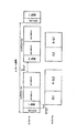
本発明の実施例によれば、図13に示すFDDフレーム構造は、マルチホップ中継をサポートするように変更されてもよい。図18Aに示すように、DL1、DL2、UL1及びUL2サブフレームは、BS-MS通信に加えてBS-RS及びRS-MS通信をサポートするために、それぞれ2つのゾーンに分割されてもよい。図13のFDDフレーム構造と同様に、図18Aのフレーム構造は、フレームの別々の部分でフレームを共有するH-FDD局の2つのグループ(グループ1及びグループ2)の協調した送信構成をサポートする。
<Operation of RS and MR-BS in FDD and H-FDD modes>
According to an embodiment of the present invention, the FDD frame structure shown in FIG. 13 may be modified to support multi-hop relay. As shown in FIG. 18A, DL1, DL2, UL1, and UL2 subframes may be divided into two zones, respectively, to support BS-RS and RS-MS communications in addition to BS-MS communications. Similar to the FDD frame structure of FIG. 13, the frame structure of FIG. 18A supports a coordinated transmission configuration of two groups (
トランスペアレントRS(T-RS:transparent RS)動作では、図18Bに示すように、DL1及びDL2サブフレームは、それぞれアクセスゾーンとトランスペアレントゾーンとに分割されてもよく、UL1及びUL2サブフレームは、それぞれアクセスゾーンと中継ゾーンとに分割されてもよい。T-RSは、MSが割り当てられるのと同じ方法でグループ1及びグループ2の一方に割り当てられてもよい。MR-BSは、複数のT-RSを各グループに同時に割り当ててもよい。この理由は、T-RSはMSであるかのように扱われ得るからである。グループ1(グループ2)に割り当てられたT-RSは、DL1/UL1(DL2/UL2)領域でデータを中継してもよい。簡単にするために、全てのRSは、そのグループのFCH/MAPが任意選択のFCH/R-MAPのみを含むように、同じグループに割り当てられてもよい。
In transparent RS (T-RS) operation, as shown in FIG. 18B, the DL1 and DL2 subframes may be divided into an access zone and a transparent zone, respectively, and UL1 and UL2 subframes are accessed respectively. It may be divided into a zone and a relay zone. A T-RS may be assigned to one of
非トランスペアレントRS(NT-RS:non-transparent RS)動作では、図18Cに示すように、DL1、DL2、UL1及びUL2サブフレームは、それぞれアクセスゾーンと中継ゾーンとに分割されてもよい。グループ1(グループ2)の能力のあるNT-RSは、UL1(UL2)を除く全体のULゾーンを使用してもよい。 In non-transparent RS (NT-RS) operation, DL1, DL2, UL1, and UL2 subframes may be divided into an access zone and a relay zone, respectively, as shown in FIG. 18C. NT-RS capable of group 1 (group 2) may use the entire UL zone except UL1 (UL2).
Rリンクチャネル記述子(RCD:R-link Channel Description) MACメッセージは、アクセス及び中継ゾーンを伝達するために使用されてもよい。アクセスゾーンは、連続的でもよく、H-FDDフレームの1つのサブフレーム内に入ってもよく、中継ゾーンは、連続的でもよく、他のサブフレーム内に入ってもよい。FCH/MAP及びR-FCH/RMAPは、それぞれ最初の送信(tx)アクセスゾーン及び中継ゾーンで送信されてもよい。 R-link channel description (RCD) MAC messages may be used to convey access and relay zones. The access zone may be continuous and may be within one subframe of the H-FDD frame, and the relay zone may be continuous and may be within another subframe. FCH / MAP and R-FCH / RMAP may be transmitted in the first transmission (tx) access zone and relay zone, respectively.
RSは、ネットワーク登録の間に、UCDからULキャリアを取得してもよい。単一無線のRSでは、最初のホップで使用されたものと同じキャリア周波数が他のホップでも使用されてもよい。デュアル無線のRSでは、RS構成CMDメッセージで伝達された第2のキャリア周波数が、FDDモードでのDLキャリアを示してもよい。FDDモードでは、RSが下位局と通信する際に使用するULキャリアを構成するために、更なるTLVが伝達されてもよい。 The RS may obtain a UL carrier from the UCD during network registration. In a single radio RS, the same carrier frequency used in the first hop may be used in other hops. In the dual radio RS, the second carrier frequency transmitted in the RS configuration CMD message may indicate a DL carrier in the FDD mode. In FDD mode, additional TLVs may be communicated to configure the UL carrier used when the RS communicates with lower stations.
非トランスペアレントRSシステムでは、全ての半二重MS/SSは、FDDモードでグループ1のユーザとして設定されてもよく、全てのRSはグループ2のユーザとして設定されてもよい(逆も同様である)。RSは、依然として全二重モードで動作してもよい。例えば、FDD対割り当てIEを介して全ての利用可能なH-FDDリソースでリソースを割り当てられてもよい。トランスペアレントRSは、DL MAP1及びDL MAP2の双方を監視し、有している転送ルールに従って中継を実行してもよい。全てのRSがトランスペアレントであるシステムでは、MS/SSはグループ間で切り替えられてもよい。
In a non-transparent RS system, all half-duplex MS / SS may be configured as
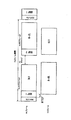
図19A及び19Bは、それぞれT-RS及びNT-RS動作の別のフレーム構成を示している。H-FDDフレーム構造の第2のサブフレームは、場合によってはトランスペアレントゾーン又は中継ゾーンとして使用される。すなわち、DL1、DL2、UL1及びUL2をゾーンに分割するのではなく、中継局は、唯一のグループ(例えば、図19A及び19Bに示すようにグループ2(すなわち、DL2及びUL2))に割り当てられる。非トランスペアレントRS動作では、中継局は自分のR-MAPを必要とするため、MAP2から利点が取り除かれる。 19A and 19B show different frame configurations for T-RS and NT-RS operation, respectively. The second subframe of the H-FDD frame structure is used as a transparent zone or a relay zone in some cases. That is, rather than dividing DL1, DL2, UL1, and UL2 into zones, relay stations are assigned to a single group (eg, group 2 (ie, DL2 and UL2) as shown in FIGS. 19A and 19B). In non-transparent RS operation, the relay station needs its own R-MAP, so the advantage is removed from MAP2.
FDDに対するTDDの1つの利点は、TDDがDL-UL送信の非対称性の特性に良く適合する点にある。図13に示す通常のH-FDDフレームは、2つのユーザのグループのみを仮定しており、DL-UL比を変化させる限られた柔軟性をもたらし、RTG/TRG及び/又はDLギャップ/ULギャップ(DL_gap/UL_gap)の要件のため、約2つのOFDMシンボルが費やされるという結果になる。 One advantage of TDD over FDD is that TDD fits well with the asymmetry characteristics of DL-UL transmissions. The normal H-FDD frame shown in FIG. 13 assumes only two groups of users and provides limited flexibility to change the DL-UL ratio, RTG / TRG and / or DL gap / UL gap. Due to the requirement of (DL_gap / UL_gap), this results in approximately 2 OFDM symbols being consumed.
図20は、3つのユーザグループ領域を有するH-FDDフレーム構成を示している。図示のように、フレーム内の3つの異なる領域で3つのユーザのグループを使用することにより、DLギャップ/ULギャップの要件が除去され、MSグループ1及び3のRTGは、それぞれ無線アイドル状態により吸収され得る。RTGの代わりにTRGが長い時間を要する場合、ULグループ送信を並び替えることにより、3つのMSグループのTRGがその代わりに吸収され得る点に留意すべきである。無線アイドル状態が調査され得るため、DL-UL比を変化させることで、柔軟性も得られる。
FIG. 20 shows an H-FDD frame configuration having three user group regions. As shown, the use of groups of three users in three different regions within the frame eliminates the DL gap / UL gap requirement, and
図21は、図20のH-FDDフレーム構成の3ホップの場合を示している。図示のように、より多くのホップを与えられると、より大きい柔軟性が予想され得る。しかし、大きい数のMSのグループが必要になる。 FIG. 21 shows a case of 3 hops in the H-FDD frame configuration of FIG. As shown, greater flexibility can be expected given more hops. However, a large number of MS groups are required.
他の変更も当業者に明らかになり、従って、本発明は特許請求の範囲に規定される。 Other modifications will be apparent to those skilled in the art and, therefore, the invention is defined in the claims.
Claims (18)
第1のキャリア周波数で前記上位局から下りリンク送信を受信するステップと、
第2のキャリア周波数で前記下位局から上りリンク送信を受信するステップと、
前記第1のキャリア周波数で前記下位局に下りリンク送信を送信するステップと、
前記第2のキャリア周波数で前記上位局に上りリンク送信を送信するステップと
有する方法。 A method of operating a relay station in a multi-hop wireless relay network, the relay station is a method of communicating with an upper station and a lower station,
Receiving a downlink transmission from the upper station at a first carrier frequency;
Receiving an uplink transmission from the subordinate station at a second carrier frequency;
Transmitting a downlink transmission to the lower station at the first carrier frequency;
Transmitting an uplink transmission to the upper station on the second carrier frequency.
それぞれの前記フレームは、前記第1のキャリア周波数の下りリンク部分を有し、前記下りリンク部分は、前記上位局と第1の複数の局との間の通信のための第1の下りリンクサブフレームと、前記上位局と第2の複数の局との間の通信のための第2の下りリンクサブフレームとを有し、
それぞれの前記フレームは、前記第2のキャリア周波数の上りリンク部分を有し、前記上りリンク部分は、前記上位局と前記第1の複数の局との間の通信のための第1の上りリンクサブフレームと、前記上位局と前記第2の複数の局との間の通信のための第2の上りリンクサブフレームとを有し、
前記第1の下りリンクサブフレームは、第1の時間間隔に対応し、前記第1の上りリンクサブフレームは、第2の時間間隔に対応し、前記第1の時間間隔及び前記第2の時間間隔は重ならず、
前記中継局は、前記第1の複数の局のうち1つであり、これにより、前記下りリンク送信の受信は、前記第1の下りリンクサブフレームで行われ、前記上りリンク送信の送信は、前記第1の上りリンクサブフレームで行われる、請求項1に記載の方法。 The communication between the relay station and the upper station is scheduled using a frame,
Each of the frames has a downlink portion of the first carrier frequency, and the downlink portion includes a first downlink sub for communication between the upper station and the first plurality of stations. A frame and a second downlink subframe for communication between the upper station and the second plurality of stations,
Each of the frames has an uplink portion of the second carrier frequency, and the uplink portion is a first uplink for communication between the upper station and the first plurality of stations. A subframe and a second uplink subframe for communication between the upper station and the second plurality of stations,
The first downlink subframe corresponds to a first time interval, the first uplink subframe corresponds to a second time interval, the first time interval and the second time interval. The intervals do not overlap,
The relay station is one of the first plurality of stations, whereby reception of the downlink transmission is performed in the first downlink subframe, and transmission of the uplink transmission is The method according to claim 1, which is performed in the first uplink subframe.
前記下りリンク送信の受信は、前記下りリンクアクセスゾーンで行われ、前記上りリンク送信の送信は、前記上りリンク中継ゾーンで行われる、請求項2に記載の方法。 The first downlink subframe is divided into a downlink access zone and a downlink transparent zone, and the first uplink subframe is divided into an uplink access zone and an uplink relay zone,
The method according to claim 2, wherein reception of the downlink transmission is performed in the downlink access zone, and transmission of the uplink transmission is performed in the uplink relay zone.
前記フレーム毎に、前記第1の時間間隔は、前記第3の時間間隔の前に生じ、前記第3の時間間隔は、前記第2の時間間隔の前に生じ、これにより、前記第1及び第3の複数の局の各受信−送信遷移ギャップは、前記それぞれのアイドル状態により吸収される、請求項6に記載の方法。 The first plurality of stations are idle during the third time interval, the second plurality of stations are idle during the second time interval, and the third A plurality of stations are idle during the first time interval;
For each frame, the first time interval occurs before the third time interval, and the third time interval occurs before the second time interval, whereby the first and The method of claim 6, wherein each receive-transmit transition gap of the third plurality of stations is absorbed by the respective idle state.
前記フレーム毎に、前記第1の時間間隔は、前記第2の時間間隔の前に生じ、前記第2の時間間隔は、前記第3の時間間隔の前に生じ、これにより、前記第1及び第3の複数の局の各受信−送信遷移ギャップは、前記それぞれのアイドル状態により吸収される、請求項8に記載の方法。 The first plurality of stations are idle during the third time interval, the second plurality of stations are idle during the third time interval, and the third A plurality of stations are idle during the second time interval;
For each frame, the first time interval occurs before the second time interval, and the second time interval occurs before the third time interval, whereby the first and 9. The method of claim 8, wherein each receive-transmit transition gap of the third plurality of stations is absorbed by the respective idle state.
前記中継局は、
第1のキャリア周波数で前記上位局から下りリンク送信を受信し、第2のキャリア周波数で前記下位局から上りリンク送信を受信する受信回路と、
前記第1のキャリア周波数で前記下位局に下りリンク送信を送信し、前記第2のキャリア周波数で前記上位局に上りリンク送信を送信する送信回路と
を有するシステム。 A multi-hop relay system having a relay station that communicates with an upper station and a lower station,
The relay station is
A receiving circuit for receiving downlink transmission from the upper station at a first carrier frequency and receiving uplink transmission from the lower station at a second carrier frequency;
A transmission circuit that transmits downlink transmission to the lower station at the first carrier frequency and transmits uplink transmission to the upper station at the second carrier frequency.
それぞれの前記フレームは、前記第1のキャリア周波数の下りリンク部分を有し、前記下りリンク部分は、前記上位局と第1の複数の局との間の通信のための第1の下りリンクサブフレームと、前記上位局と第2の複数の局との間の通信のための第2の下りリンクサブフレームとを有し、
それぞれの前記フレームは、前記第2のキャリア周波数の上りリンク部分を有し、前記上りリンク部分は、前記上位局と前記第1の複数の局との間の通信のための第1の上りリンクサブフレームと、前記上位局と前記第2の複数の局との間の通信のための第2の上りリンクサブフレームとを有し、
前記第1の下りリンクサブフレームは、第1の時間間隔に対応し、前記第1の上りリンクサブフレームは、第2の時間間隔に対応し、前記第1の時間間隔及び前記第2の時間間隔は重ならず、
前記中継局は、前記第1の複数の局のうち1つであり、これにより、前記下りリンク送信の受信は、前記第1の下りリンクサブフレームで行われ、前記上りリンク送信の送信は、前記第1の上りリンクサブフレームで行われる、請求項10に記載のシステム。 The communication between the relay station and the upper station is scheduled using a frame,
Each of the frames has a downlink portion of the first carrier frequency, and the downlink portion includes a first downlink sub for communication between the upper station and the first plurality of stations. A frame and a second downlink subframe for communication between the upper station and the second plurality of stations,
Each of the frames has an uplink portion of the second carrier frequency, and the uplink portion is a first uplink for communication between the upper station and the first plurality of stations. A subframe and a second uplink subframe for communication between the upper station and the second plurality of stations,
The first downlink subframe corresponds to a first time interval, the first uplink subframe corresponds to a second time interval, the first time interval and the second time interval. The intervals do not overlap,
The relay station is one of the first plurality of stations, whereby reception of the downlink transmission is performed in the first downlink subframe, and transmission of the uplink transmission is The system according to claim 10, which is performed in the first uplink subframe.
前記下りリンク送信の受信は、前記下りリンクアクセスゾーンで行われ、前記上りリンク送信の送信は、前記上りリンク中継ゾーンで行われる、請求項11に記載のシステム。 The first downlink subframe is divided into a downlink access zone and a downlink transparent zone, and the first uplink subframe is divided into an uplink access zone and an uplink relay zone,
The system according to claim 11, wherein reception of the downlink transmission is performed in the downlink access zone, and transmission of the uplink transmission is performed in the uplink relay zone.
前記フレーム毎に、前記第1の時間間隔は、前記第3の時間間隔の前に生じ、前記第3の時間間隔は、前記第2の時間間隔の前に生じ、これにより、前記第1及び第3の複数の局の各受信−送信遷移ギャップは、前記それぞれのアイドル状態により吸収される、請求項15に記載のシステム。 The first plurality of stations are idle during the third time interval, the second plurality of stations are idle during the second time interval, and the third A plurality of stations are idle during the first time interval;
For each frame, the first time interval occurs before the third time interval, and the third time interval occurs before the second time interval, whereby the first and The system of claim 15, wherein each receive-transmit transition gap of the third plurality of stations is absorbed by the respective idle state.
前記フレーム毎に、前記第1の時間間隔は、前記第2の時間間隔の前に生じ、前記第2の時間間隔は、前記第3の時間間隔の前に生じ、これにより、前記第1及び第3の複数の局の各受信−送信遷移ギャップは、前記それぞれのアイドル状態により吸収される、請求項17に記載のシステム。 The first plurality of stations are idle during the third time interval, the second plurality of stations are idle during the third time interval, and the third A plurality of stations are idle during the second time interval;
For each frame, the first time interval occurs before the second time interval, and the second time interval occurs before the third time interval, whereby the first and The system of claim 17, wherein each receive-transmit transition gap of the third plurality of stations is absorbed by the respective idle state.
Applications Claiming Priority (3)
| Application Number | Priority Date | Filing Date | Title |
|---|---|---|---|
| US23951409P | 2009-09-03 | 2009-09-03 | |
| US61/239,514 | 2009-09-03 | ||
| PCT/CA2010/001351 WO2011026224A1 (en) | 2009-09-03 | 2010-09-03 | Frequency division duplexing in multihop relay networks |
Publications (1)
| Publication Number | Publication Date |
|---|---|
| JP2013504223A true JP2013504223A (en) | 2013-02-04 |
Family
ID=43648804
Family Applications (1)
| Application Number | Title | Priority Date | Filing Date |
|---|---|---|---|
| JP2012527164A Pending JP2013504223A (en) | 2009-09-03 | 2010-09-03 | Frequency division duplex and half duplex frequency division duplex in multi-hop relay networks |
Country Status (8)
| Country | Link |
|---|---|
| EP (2) | EP4164140A1 (en) |
| JP (1) | JP2013504223A (en) |
| CN (1) | CN102792609A (en) |
| BR (1) | BR112012004801A2 (en) |
| CA (1) | CA2773052C (en) |
| IN (1) | IN2012DN02001A (en) |
| RU (1) | RU2012112888A (en) |
| WO (1) | WO2011026224A1 (en) |
Cited By (1)
| Publication number | Priority date | Publication date | Assignee | Title |
|---|---|---|---|---|
| KR20160010437A (en) * | 2013-05-22 | 2016-01-27 | 엘지전자 주식회사 | Structure of full duplex radio region applied in radio access system supporting full duplex radio scheme, and method and apparatus for allocating same |
Families Citing this family (3)
| Publication number | Priority date | Publication date | Assignee | Title |
|---|---|---|---|---|
| JP5187909B2 (en) * | 2009-10-05 | 2013-04-24 | 株式会社エヌ・ティ・ティ・ドコモ | Mobile communication method and relay node |
| US9014110B2 (en) * | 2011-07-18 | 2015-04-21 | Qualcomm Incorporated | Enabling half-duplex operation |
| CN106937365B (en) * | 2015-12-31 | 2018-06-26 | 深圳友讯达科技股份有限公司 | Wireless self-organizing network nodes communication means and node |
Family Cites Families (1)
| Publication number | Priority date | Publication date | Assignee | Title |
|---|---|---|---|---|
| US20100278123A1 (en) * | 2007-12-10 | 2010-11-04 | Nortel Networks Limited | Wireless communication frame structure and apparatus |
-
2010
- 2010-09-03 CN CN2010800496505A patent/CN102792609A/en active Pending
- 2010-09-03 IN IN2001DEN2012 patent/IN2012DN02001A/en unknown
- 2010-09-03 WO PCT/CA2010/001351 patent/WO2011026224A1/en active Application Filing
- 2010-09-03 EP EP22196827.4A patent/EP4164140A1/en not_active Withdrawn
- 2010-09-03 JP JP2012527164A patent/JP2013504223A/en active Pending
- 2010-09-03 EP EP10813196.2A patent/EP2474107A4/en not_active Ceased
- 2010-09-03 RU RU2012112888/07A patent/RU2012112888A/en not_active Application Discontinuation
- 2010-09-03 BR BR112012004801A patent/BR112012004801A2/en not_active Application Discontinuation
- 2010-09-03 CA CA2773052A patent/CA2773052C/en active Active
Non-Patent Citations (9)
| Title |
|---|
| JPN6012023566; Zhifeng Tao, et.al.: 'Frame Structure Design for IEEE 802.16j Mobile Multihop Relay (MMR) Networks' IEEE Global Telecommunications Conference, 2007. GLOBECOM '07. , 20071126, pages.4301-4306, IEEE * |
| JPN6014030921; Steven W.Peters, et al.: 'The future of WiMAX: Multihop relaying with IEEE 802.16j' IEEE Communications Magazine Volume:47, Issue:1, 200901, pages.104-111, IEEE * |
| JPN6014030923; VASKEN GENC, et al.: 'IEEE 802.16J relay-based wireless access networks: an overview' IEEE Wireless Communications Volume:15,Issue:5, 200810, pages.56-63, IEEE * |
| JPN7011002714; Gang Shen, et.al.: 'Recommendations on IEEE 802.16j' IEEE 802.16j contribution by Alcatel , 20060508, 全文全図, IEEE * |
| JPN7011002740; David Comstock, et.al.: 'A Flexible Multi-hop Frame Structure for IEEE 802.16j' IEEE 802.16 Broadband Wireless Access Working Group Contribution IEEE C802.16j-06_163, 20061108, 第0-10頁, IEEE * |
| JPN7011002741; Mike Hart: 'Frame structure for support of multihop relaying' IEEE 802.16 Broadband Wireless Access Working Group Contribution IEEE C802.16j-07/012, 20070108, 第0-6頁, IEEE * |
| JPN7012001700; Jeffrey Z. Tao, et.al.: 'An adaptive frame structure for OFDMA-based mobile multi-hop relay networks' IEEE 802.16j Mobile Multihop Relay Task Group Contribution IEEE C802.16j-07/117r1, 20070115, pages.1-9, IEEE * |
| JPN7014000002; Gamini Senarath, et al.: 'FDD and H-FDD frame structure for transparent RS and MR-BS' IEEE 802.16's Relay Task Group Documents, [online] IEEE C802.16j-08/158r5, 20081112, pages.1-3, IEEE * |
| JPN7014000003; Gamini Senarath, et al.: 'FDD and H-FDD frame structure for TTR RS and MR-BS' IEEE 802.16 Broadband Wireless Access Working Group Documents, [online] IEEE C802.16j-08/157r5, 20081111, pages.1-4, IEEE 802.16 Broadband Wireless Access Working Grou * |
Cited By (2)
| Publication number | Priority date | Publication date | Assignee | Title |
|---|---|---|---|---|
| KR20160010437A (en) * | 2013-05-22 | 2016-01-27 | 엘지전자 주식회사 | Structure of full duplex radio region applied in radio access system supporting full duplex radio scheme, and method and apparatus for allocating same |
| KR102232425B1 (en) | 2013-05-22 | 2021-03-26 | 엘지전자 주식회사 | Structure of full duplex radio region applied in radio access system supporting full duplex radio scheme, and method and apparatus for allocating same |
Also Published As
| Publication number | Publication date |
|---|---|
| BR112012004801A2 (en) | 2017-05-30 |
| WO2011026224A1 (en) | 2011-03-10 |
| RU2012112888A (en) | 2013-10-20 |
| CN102792609A (en) | 2012-11-21 |
| EP2474107A4 (en) | 2016-05-25 |
| EP4164140A1 (en) | 2023-04-12 |
| CA2773052C (en) | 2018-05-22 |
| CA2773052A1 (en) | 2011-03-10 |
| IN2012DN02001A (en) | 2015-07-24 |
| EP2474107A1 (en) | 2012-07-11 |
Similar Documents
| Publication | Publication Date | Title |
|---|---|---|
| US8929303B2 (en) | Control and data channels for advanced relay operation | |
| US8576753B2 (en) | System and method for wireless relay frame structure, protocol, and operation | |
| US8488634B2 (en) | Use of first and second preambles in wireless communication signals | |
| KR101614982B1 (en) | The use of first and second preambles in wireless communication signals | |
| JP4875504B2 (en) | OFDMA radio system and relay station | |
| JP2014209742A (en) | Method, communication stations, base station and communication system using relay stations with spectrum aggregation | |
| US20110070821A1 (en) | Method and apparatus for transmitting and receiving signal in relay station | |
| TW200822607A (en) | Communication systems | |
| JP2010063124A (en) | Multi-hop wireless communication system, base station device, relay device, and user device and method | |
| KR101612558B1 (en) | Method for transmitting frames in a wireless communication system including relay station | |
| KR20120042905A (en) | Communication system, communication apparatus, communication method and computer program product | |
| TW201029362A (en) | Communication systems | |
| JP5466241B2 (en) | Relaying technique suitable for user equipment in downlink | |
| US20130070662A1 (en) | Frequency Division Duplexing and Half Duplex Frequency Division Duplexing in Multihop Relay Networks | |
| CA2773052C (en) | Frequency division duplexing in multihop relay networks | |
| IL194097A (en) | Ofdma-based operation of a wireless subscriber terminal in a plurality of cells | |
| US8750175B2 (en) | Apparatus and method for transceiving a signal using a predetermined frame structure in a wireless communication system | |
| JP4871784B2 (en) | Wireless communication device | |
| US20090252081A1 (en) | Apparatus and method for supporting various systems in a multihop relay broadband wireless communication system | |
| KR101636581B1 (en) | Method and apparatus for transmitting ans receiving signal in relay station |
Legal Events
| Date | Code | Title | Description |
|---|---|---|---|
| RD02 | Notification of acceptance of power of attorney |
Free format text: JAPANESE INTERMEDIATE CODE: A7422 Effective date: 20130726 |
|
| A621 | Written request for application examination |
Free format text: JAPANESE INTERMEDIATE CODE: A621 Effective date: 20130820 |
|
| A977 | Report on retrieval |
Free format text: JAPANESE INTERMEDIATE CODE: A971007 Effective date: 20131225 |
|
| A131 | Notification of reasons for refusal |
Free format text: JAPANESE INTERMEDIATE CODE: A131 Effective date: 20140108 |
|
| A521 | Request for written amendment filed |
Free format text: JAPANESE INTERMEDIATE CODE: A523 Effective date: 20140407 |
|
| A02 | Decision of refusal |
Free format text: JAPANESE INTERMEDIATE CODE: A02 Effective date: 20140723 |
|
| A521 | Request for written amendment filed |
Free format text: JAPANESE INTERMEDIATE CODE: A523 Effective date: 20141120 |
|
| A911 | Transfer to examiner for re-examination before appeal (zenchi) |
Free format text: JAPANESE INTERMEDIATE CODE: A911 Effective date: 20141201 |
|
| A912 | Re-examination (zenchi) completed and case transferred to appeal board |
Free format text: JAPANESE INTERMEDIATE CODE: A912 Effective date: 20150109 |