JP4875504B2 - OFDMA radio system and relay station - Google Patents
OFDMA radio system and relay station Download PDFInfo
- Publication number
- JP4875504B2 JP4875504B2 JP2007010986A JP2007010986A JP4875504B2 JP 4875504 B2 JP4875504 B2 JP 4875504B2 JP 2007010986 A JP2007010986 A JP 2007010986A JP 2007010986 A JP2007010986 A JP 2007010986A JP 4875504 B2 JP4875504 B2 JP 4875504B2
- Authority
- JP
- Japan
- Prior art keywords
- station
- layer
- relay
- processing unit
- frame
- Prior art date
- Legal status (The legal status is an assumption and is not a legal conclusion. Google has not performed a legal analysis and makes no representation as to the accuracy of the status listed.)
- Expired - Fee Related
Links
Images

Landscapes
- Mobile Radio Communication Systems (AREA)
- Radio Relay Systems (AREA)
Description
本発明は、直交周波数分割多重アクセス(OFDMA)方式の信号を中継するための中継局等に関する。 The present invention relates to a relay station or the like for relaying an orthogonal frequency division multiple access (OFDMA) signal.
現在、Mobile WiMAXと称されるIEEE802.16e規格の実用化が進められている(例えば非特許文献1参照。)。またそのようなモバイル環境においてマルチホップを行うためのIEEE802.16jの規格化が検討されている(例えば非特許文献2及び4参照。)。
Currently, the IEEE 802.16e standard called Mobile WiMAX is being put into practical use (for example, see Non-Patent Document 1). Further, standardization of IEEE 802.16j for performing multi-hop in such a mobile environment has been studied (for example, see Non-Patent
また、基地局からの第1無線周波数帯の電波を受信し、異なる第2無線周波数帯に変換して端末に送信するOFDM方式の無線中継器が知られる(例えば特許文献1参照。)。 There is also known an OFDM wireless repeater that receives radio waves in a first radio frequency band from a base station, converts the radio waves into different second radio frequency bands, and transmits them to a terminal (see, for example, Patent Document 1).
しかしながら、従来の特許文献1の無線中継器では、基地局用に割当てられた第1無線周波数帯の帯域幅を維持し、周波数のみ変換して中継エリアに再送信するために、2つの搬送波が必要となる。従って、1搬送波の占有帯域幅が10MHz以上となりうる広帯域移動無線通信システムに用いると、周波数資源が有効利用できないという問題があった。
However, in the conventional wireless repeater of
本発明は、上述した背景からなされたものであり、周波数資源が有効利用することができるOFDMA無線システム及び中継局等を提供することを目的とする。 The present invention has been made from the above-described background, and an object thereof is to provide an OFDMA radio system, a relay station, and the like that can effectively use frequency resources.
上記目的を達成するために、本発明にかかるOFDMA無線システム及び中継局は、
加入者局と、1乃至複数の中継局と、加入者局や中継局を収容する基地局とを備えるOFDMA無線システムにおいて、
前記中継局(RS)は、前記中継局が属する基地局(MR−BS)が使用する搬送波に含まれる複数のサブキャリアのうち、当該基地局が送信または受信しないサブキャリア上及び時間上の領域内において測定した雑音+同一チャネル干渉電力の小さな一部のサブキャリアを、当該領域において当該中継局に属する加入者局との間の送信または受信に用い、
前記基地局は、搬送波に含まれるサブキャリアの全てを用いている状態で当該基地局の配下に初めて中継局が出現したときに、用いるサブキャリアの数を減らした時間を設けることを特徴とする。
To achieve the above object, an OFDMA radio system and a relay station according to the present invention include:
In an OFDMA wireless system comprising a subscriber station, one or more relay stations, and a base station that accommodates the subscriber station or relay station,
The relay station (RS) is a region on a subcarrier and a time that is not transmitted or received by the base station among a plurality of subcarriers included in a carrier used by a base station (MR-BS) to which the relay station belongs. A part of subcarriers having a small noise + co-channel interference power measured in the above are used for transmission or reception with a subscriber station belonging to the relay station in the area,
The base station provides a time when the number of subcarriers to be used is reduced when a relay station first appears under the base station in a state where all of the subcarriers included in a carrier wave are used. .
また、加入者局と、1乃至複数の中継局と、加入者局や中継局を収容する基地局とを備えるOFDMA無線システムに用いられ、上流局となる基地局若しくは中継局と、下流局となる加入者局若しくは中継局との間の中継をMAC層で行う中継局であって、
夫々独立したアンテナを有し、OFDMA無線システムの無線信号の送受信を行うとともに、RSSIを測定する複数のレイヤ1処理部(1、2)と、
前記レイヤ1処理部の夫々に、上流局からの下り信号のRSSIを測定させて、当該RSSIが最大のレイヤ1処理部を前記上流局との通信用に割当て、他のいずれかのレイヤ1処理部を下流局との通信用に割当てるとともに、
前記下流局との通信用に割当てられたレイヤ1処理部に、前記上流局が使用する搬送波に含まれる複数のサブキャリアセットの雑音+同一チャネル干渉電力を、前記上流局が送信しないサブキャリア上及び時間上の領域内において測定させて、当該干渉電力の小さな1つのサブキャリアセットを、当該領域においてのみ前記下流局への送信に使用させるレイヤ2処理部(3)と、を備える。
Further, it is used in an OFDMA wireless system including a subscriber station, one or more relay stations, and a base station that accommodates the subscriber station or the relay station, and a base station or relay station that is an upstream station, a downstream station, A relay station that performs relaying between a subscriber station or a relay station in the MAC layer,
A plurality of
Each of the
On the subcarrier where the upstream station does not transmit the noise of the plurality of subcarrier sets included in the carrier used by the upstream station + the co-channel interference power to the
本発明にかかるOFDMA無線システム及び中継局等によれば、移動機の受信端において、無線基地局の送信信号と無線中継局の送信信号が混信することなく、無線基地局と同じ搬送波を使用して、周波数資源が有効を利用することができる。 According to the OFDMA radio system and relay station according to the present invention, at the receiving end of the mobile device, the transmission signal of the radio base station and the transmission signal of the radio relay station do not interfere with each other, and the same carrier wave as that of the radio base station is used. Thus, the frequency resource can be utilized effectively.
以下の説明は、IEEE802.16に規定されているOFDMA物理層を用いることを前提とし、本例の説明に用いる術語の定義は、特に断らない限り当該規定に従うものとする。
また、各実施例で説明する構成の全ての組み合わせが本発明に必須であるとは限らない。また各実施例の特徴の任意の組み合わせや、引用した従来技術との組み合わせも本発明に含まれうる。
The following description is based on the premise that the OFDMA physical layer specified in IEEE 802.16 is used, and the definition of the terminology used in the description of this example is based on that specification unless otherwise specified.
In addition, all combinations of configurations described in each embodiment are not necessarily essential to the present invention. In addition, any combination of the features of the embodiments and combinations with the cited prior art can be included in the present invention.
先ず、本発明の理解を助けるために、OFDMAシステム、およびOFDMAにおける副搬送波の棲み分けの類型について説明する。
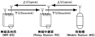
図1は、OFDMAシステムの概略図である。OFDMAは、副搬送波毎、及びOFDMシンボル毎に異なるユーザに割当てることでユーザ多重を行ったアクセス方式である。OFDMAシステムは、無線基地局(BS)と、MSと、無線中継局(RS)とから構成され、MSを所持するユーザは、直接あるいは間接的にBSにアクセスすることで通信を行う。
First, in order to help the understanding of the present invention, an OFDMA system and types of subcarrier segregation in OFDMA will be described.
FIG. 1 is a schematic diagram of an OFDMA system. OFDMA is an access scheme in which user multiplexing is performed by assigning different users to each subcarrier and each OFDM symbol. The OFDMA system is composed of a radio base station (BS), an MS, and a radio relay station (RS), and a user who owns the MS communicates by accessing the BS directly or indirectly.
有限の収容エリアを形成する無線基地局(BS)は、収容エリアに隙間が生じないような密度で設置されるのが理想であるが、バックボーンに接続されずにBSとMSの中継を行うRSを用いてエリアを展開したほうが、初期投資費用の点において優れている。
無線中継局(RS)を配下に従えてマルチホップリレーを行わせることができる無線基地局を特にMR−BSと称す。
Ideally, radio base stations (BS) that form a finite accommodation area should be installed at a density that does not create a gap in the accommodation area, but an RS that relays BS and MS without being connected to the backbone. It is better in terms of the initial investment cost to expand the area using.
A radio base station capable of performing multi-hop relay under the control of a radio relay station (RS) is particularly referred to as MR-BS.
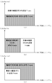
図2は、無線基地局(MR−BS)と無線中継局(RS)とで物理層資源の棲み分けを行う際のフレーム構成を分類した図である。横軸はOFDMAシンボル(つまり時間)、縦軸はサブチャネル(つまり周波数)を示している。1搬送波中に複数(例えば1024本)の副搬送波が存在し、その中から複数の副搬送波を連続あるいは不連続に取り出して束ねたものをサブチャネルとする。従って縦軸のサブチャネルは周波数上で必ずしも連続しているとは限らない。また図1ではMR−BSとRSとで送信フレームが同期している場合を示したが、これに限定するものではない。 FIG. 2 is a diagram in which frame configurations when physical layer resources are segregated between a radio base station (MR-BS) and a radio relay station (RS) are classified. The horizontal axis indicates OFDMA symbols (that is, time), and the vertical axis indicates subchannels (that is, frequency). A plurality of (for example, 1024) subcarriers exist in one carrier wave, and a subchannel is a bundle of a plurality of subcarriers extracted continuously or discontinuously. Therefore, the subchannels on the vertical axis are not always continuous in frequency. Moreover, although the case where the transmission frame was synchronized with MR-BS and RS was shown in FIG. 1, it is not limited to this.
図2(a)は、MR−BSとRSとにおいて、サブチャネルを異ならせて棲み分けを行うフレームを示し、図2(b)は、OFDMAシンボルを異ならせて棲み分けを行うフレームを示し、縦軸図2(c)は、サブチャネルとOFDMAシンボルとの組み合わせにより棲み分けを行うフレームを示している。
(a)から(c)に共通することは、1つの搬送波の中で、MR−BSとRSとで使用する資源が重複しないように、棲み分けがなされていることである。
FIG. 2 (a) shows a frame in which the sub-channels are differentiated in MR-BS and RS, and FIG. 2 (b) shows a frame in which the OFDMA symbols are differentiated and divided. The vertical axis of FIG. 2 (c) shows a frame that is divided by a combination of subchannels and OFDMA symbols.
What is common to (a) to (c) is that segregation is performed so that resources used in the MR-BS and the RS do not overlap in one carrier wave.
以下、実施例1にかかるOFDMAシステムを説明する。本例のOFDMAシステムは、無線中継局(RS)が2つのアンテナを備え、一方を無線基地局(MR−BS)側、他方をMS側に割り当て、また直属の上流局(MR−BS若しくはRS)と異なる部分周波数(セグメント)を下流局(MS若しくはRS)との通信に用いる点などを特徴とする。
実施例1のOFDMAシステムの構成は、図1と同等とし、複信方式にはTDD(Time Division Duplex)若しくはHFDD(Half Frequency Division Duplex)を用いる。
The OFDMA system according to the first embodiment will be described below. In the OFDMA system of this example, a radio relay station (RS) is provided with two antennas, one is assigned to the radio base station (MR-BS) side, the other is assigned to the MS side, and a direct upstream station (MR-BS or RS) is assigned. ) And a different partial frequency (segment) is used for communication with a downstream station (MS or RS).
The configuration of the OFDMA system according to the first embodiment is the same as that in FIG. 1, and TDD (Time Division Duplex) or HFDD (Half Frequency Division Duplex) is used as the duplex method.
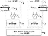
図3は、本実施例のRSの機能概略図である。本例のRSはレイヤ1処理部1と、レイヤ1処理部2と、レイヤ2処理部3とを備える。
レイヤ1処理部1及び2は、ほぼ同一の構成であって、それぞれアンテナ11と21、RF部12と22、PHY信号処理部13と23を備える。レイヤ1は物理層(PHY)を意味する。
FIG. 3 is a functional schematic diagram of the RS of this embodiment. The RS of this example includes a
The
アンテナ11、21は、MR−BSとの伝播路若しくは伝播路特性が異なるような、互いに独立したアンテナであり、指向性を有しても有しなくてもよい。一例として偏波特性を異ならせても良い。特に見通し通信(LOS:Line Of Site)が可能な場合、一方のアンテナを、直属の上流局(MR−BS若しくはRS)の向きに対し利得が高くなる指向性アンテナにし、他方のアンテナを、当該RSが収容するエリアに対し利得が高くなる指向性アンテナにするとよい。或いは、2つのアンテナ間に着脱可能な反射板を設け、RSとして使用するときはアンテナ間の結合量を小さくし、BSに転用したときは反射板を取り外してMIMO動作できるようにしてもよい。
RF部12、22は、送信信号や受信信号の増幅や、周波数変換や、チャネル(キャリア)選択や、それらの制御等を行うフロントエンド部である。
PHY信号処理部13、23は、後述するように送信信号に対しインターリブ処理、符号化処理、FFT処理などの物理層の信号処理を行い、受信信号に対してはその逆の処理を行う。
The
The
As described later, the PHY
レイヤ2処理部3は、MAC(Medium Access Control)を行う部分であって、送信信号に対し、上位レイヤから入力されたパケットのヘッダを圧縮し、MAC―PDU(MAC-Protocol Data Units)を作成し、1乃至複数のMAC−PDUを結合してバースト(後述する)という単位で出力し、受信信号に対してはその逆の処理を行う。また、物理層のための適応リンク制御、QoS制御、ネットワークへの参加や切断の制御を行い、それらに必要な情報信号(後述するFCH、MAP、レインジング、MACメッセージ、等)をレイヤ1処理部1並び2と入出力する。RSにおいてはまた、一方のレイヤ1処理部から入力されたMAPやバーストをレイヤ2レベルで再構成し、他方のレイヤ1処理部に中継する機能等を備える。レイヤ2処理部3の機能は、Network ProcessorやMPU(Micro Processing Unit)とそのソフトウェアで実現されることが多い。
The
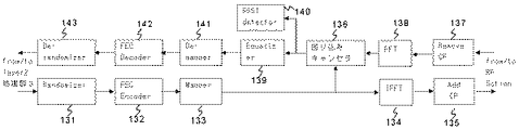
図4は、PHY信号処理部13、23の内部構成図である。図4は伝送データの流れを主に説明するものであって、通常備えうる制御線などは省略されている。
ランダマイザ131は、バースト誤り耐性を改善するために、レイヤ2処理部3から入力されたバーストをランダム化して出力する。
FECエンコーダ132は、受信側で前方誤り訂正を行うために、ランダマイザ131からの入力信号を冗長符号化して出力する。符号化率はレイヤ2処理部3から与えられる。
FIG. 4 is an internal configuration diagram of the PHY
The
The
マッパー133は、レイヤ2処理部3からの指示に従い、入力された符号を変調シンボルに変換し、対応するOFDMシンボル及び各サブチャネル(ビン)に割当てる。
IFFT134は、マッパー133から入力された変調シンボルを、IFFTにより時間領域信号に変換し、OFDMシンボルとして出力する。
CP付加器135は、IFFT134から入力されたOFDMシンボルに、CP(Cyclic Prefix)を付加し、送信信号としてRF部12等に出力する。
The
The IFFT 134 converts the modulation symbol input from the
The
CP除去器137は、CPの相関検出などによりOFDMシンボル同期を確立し、適切なFFTサイズでOFDMシンボルを切り出して出力する。
FFT138は、CP除去器137から入力されたOFDMシンボルを、FFTにより周波数領域信号に変換し、各副搬送波の変調シンボルを出力する。
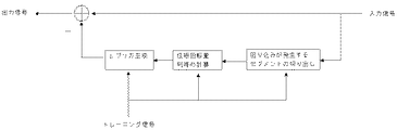
回り込みキャンセラ136は、他方のレイヤ1処理部1又は2のマッパー133から入力された変調シンボルをトレーニング信号として、FFT138から入力された各副搬送波の変調シンボルに重畳している回り込み信号の位相回転量、利得を副搬送波毎に算出し、この算出値とトレーニング信号から回り込み信号のレプリカを作り出し、FFT138の変調シンボルから差し引くことで、他方のアンテナから回り込む送信信号を打ち消す。回り込みキャンセラ136の内部構成を図8に示す。図8の回り込みキャンセラ136では、回り込みは1セグメント(後述する)内で発生するものとして、キャンセルするセグメントの切り出しを行っている。
The FFT 138 converts the OFDM symbol input from the
The wraparound canceller 136 uses the modulation symbol input from the
等化器139は、回り込みキャンセラ136から入力された各副搬送波の変調シンボルに対し、周波数領域の伝播路特性H(ω)をそれぞれ乗算することで、OFDMシンボルの等化を行う。伝播路特性は、副搬送波中に周波数(及び時間)上で分散して存在する既知のパイロットキャリアを基準として推定し、パイロットキャリアが存在しない部分については補間する。この補間は、当該変調シンボルを送信した局毎に行い、位相回転も補償する(つまりH(ω)を複素数とする)場合は、位相の補間は遅延時間換算で行う。また、伝播路推定の結果により、OFDMシンボル同期が修正されうる。また、MIMOを行う場合は、送受信する複数のアンテナ間の伝播路に対応して、複数の伝播路特性が推定されうる。
The
RSSI測定部140は、FFT138から入力された各副搬送波の変調シンボルであって、フレームの先頭に位置する既知のプリアンブルに対し、その電力等を測定し、(1シンボル当りの)RSSI(Received Signal Strength Indicator)やCINR(Carrier toInterference-plus-Noise Ratio)を計算して出力する。
デマッパ141は、等化器139から入力された変調シンボルに対し、マッパー133と逆の処理を行って符号を出力する。
FECデコーダ142は、デマッパ141から入力された符号を誤り訂正復号して出力する。
デランダマイザ143は、FECデコーダ142から入力された信号に対し、ランダマイザ131と逆の処理を行って元のバーストデータをレイヤ2処理部3に出力する。
The
The
The
The
図4は、RSのPHY信号処理部13等として説明したが、回り込みキャンセラ136を備えた点を除けば、MR−BS、MSと同等である。そのため、レイヤ2処理部3のファームウェアの変更により、MR−BSとRSを切り替えることもできる。
PHY信号処理部13等は、DSP(Digital Signal Processor)やFPGA(Field Programmable Gate Array)等で実現されることが多い。
FIG. 4 is described as the RS PHY
The PHY
次に、新たなRSの設置から中継動作を行うまでに、本例のRS及びMR−BSのMAC層及び物理層で必要となる動作を順を追って説明する。
本例の動作では、RSの電源投入後にRSが近隣のMR−BS等を見つけて自己の存在を登録する過程1と、登録を受けたMR−BS等が必要に応じ副搬送波のセットを変更する過程2と、過程2を受けてRSがMR−BS等と適切なアンテナで無線及びMACリンクを再確立する過程3と、RSが干渉を測定しMS等との通信に用いる副搬送波のセットやフレーム長を決定する過程4と、中継動作を行う過程5とを行う。
Next, operations required in the MAC layer and physical layer of the RS and MR-BS in this example from the installation of a new RS to the relay operation will be described in order.
In the operation of this example, after the RS is turned on, the RS finds a nearby MR-BS etc. and registers its existence, and the registered MR-BS etc. changes the subcarrier set as necessary. A
まず、上記過程1の詳細を説明する。過程1の処理は主にRS側で行われる。
最初に過程101として、RSの電源を投入する。
次に過程102として、レイヤ1処理部1が、適宜MAC層からの指示を受けて任意のMR−BSやRSが送信している搬送波を探す。例えば、受信周波数を掃引し、CP除去部137でOFDMシンボル同期が取得できた場合、その周波数に搬送波が存在すると推定する。
次に過程103として、レイヤ1処理部1は、過程103で見つかった搬送波においてシンボルタイミング及びフレームタイミング同期を行い、受信したフレームに定期的に含まれるDCD(Downlink Channel Descriptor)及びUCD(Uplink Channel Descriptor)を検出し、変調方式などのパラメータを取得し、当該MR−BS等の送信フレーム(後述する図6参照)を復調できる状態にする。復調できなければ過程101に戻って搬送波を探す。
次に過程104として、レイヤ1処理部1のRSSI測定部140が、当該MR−BS等の送信フレームに含まれるプリアンブルのRSSIを測定してレイヤ2処理部に報告するとともに、レイヤ2処理部3はそのRSSIをRSSI1として記憶する。
次に過程105として、他方のレイヤ1処理部2が、過程102から104と同様の処理を行い、レイヤ2処理部3がRSSI2を記憶する。
First, the details of the
First, in step 101, the RS is turned on.
Next, as step 102, the
Next, as step 103, the
Next, as step 104, the
Next, as step 105, the
次に過程106として、レイヤ2処理部3は、記憶しているRSSI1とRSSI2を比較し、値の大きい方に対応するレイヤ1処理部1又は2を上流局(MR−BS等)との通信に使用するレイヤ1処理部として決定する。決定されたレイヤ1処理部を以後、レイヤ1処理部(BS用)と称し、他方のレイヤ1処理部をレイヤ1処理部(MS用)と称す。この処理は、アンテナ11等に指向性アンテナを用いたときに威力を発揮する。
次に過程107として、レイヤ1処理部(BS用)は、MR−BS等が送信しているフレームを受信し復調する。
最後に過程108として、レイヤ2処理部3は、レイヤ1処理部(BS用)を用いてMR−BS等に自局(RS)の存在を登録する。具体的には、送信電力を徐々に上げながら初期レインジングメッセージを送信し、MR−BSからレインジング成功の応答があったら、次に機能要求メッセージを送信し、MR−BSから機能ネゴシエーション成功の応答があったら、MR−BSと鍵交換による認証を行い、最後に登録要求メッセージを送信しMR−BSからの登録応答を確認する。
MR−BSとRS間の電波伝搬環境として見通し通信を想定すると、上述のような選択方式でも適切に選択することができる。
Next, as step 106, the
In step 107, the
Finally, as step 108, the
Assuming line-of-sight communication as the radio wave propagation environment between the MR-BS and the RS, the above selection method can also be selected appropriately.
次に、上記過程2の詳細を説明する。過程2の処理は主にMR−BS側で行われる。
最初に過程201として、過程108のメッセージを受信したMR−BSは、現在MR−BSが使用可能な副搬送波(あるいはサブチャネル)の全て用いて送信している(例えば(Full usage of subchannels)ならば、副搬送波を複数(例えば3)のセットにセグメント化し、そのうちの1セットのみを用いてDLSub-frame(後述する図5参照)を送信する区間を設ける。もし既に1セットのみで送信を行っている場合は、変更は必要ない。送信に用いる1セットは、セル設計時に予め定めたものか、当該MR−BSにおいてCINR等が最も良いものを用いる。
Next, details of the
First, as step 201, the MR-BS that has received the message of step 108 transmits using all the subcarriers (or subchannels) that the MR-BS can currently use (for example, (Full usage of subchannels)). For example, the subcarrier is segmented into a plurality of sets (for example, 3), and a section for transmitting a DLSub-frame (see FIG. 5 described later) using only one set is provided. However, one set used for transmission is determined in advance at the time of cell design, or the one with the best CINR in the MR-BS is used.
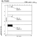
図5は、本例のサブチャネルのセグメント化を示す図であり、非特許文献1の8.4.4.4から抜粋したものである。セグメント化は、同一セル内でセクタを構成することを目的の1つとしている。横軸はOFDMAシンボルインデックス、縦軸はサブチャネルインデックスである。複数のサブチャネルは3つのセグメントに分割されて割当てられ、各セグメントの先頭の1シンボル目には各セルID及び各セグメント固有のプリアンブルが設けられ、その次にFCH(FrameControl Header)が続く。各セグメントの間にはガードバンドが設けられる。または、各セグメントに割り当てられる副搬送波を複数のサブチャネルに分散させれば、周波数ダイバーシティや隣接セル干渉低減の効果が維持できる。
FIG. 5 is a diagram showing segmentation of the subchannel in this example, which is extracted from 8.4.4.4 of
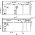
図6は、本例のMR−BSとRS間、及びRSとMS間の無線フレームの一構成例であり、非特許文献2からの抜粋である。図6(a)がMR−BS等とRSの間で用いられる無線フレーム(MR-BS Frame)、図6(b)がRSとMS等の間で用いられる無線フレーム(RSFrame)であり、両方ともセグメント化後の1セグメント分を示している。図6(a)と(b)は横軸(時間)をそろえて表記しており、本例ではフレーム及びサブフレームタイミングは、MR−BSとその配下のRSの間で同期している。そのため、MR−BSとRSの送信タイミングは重なりうる。
FIG. 6 is a configuration example of a radio frame between the MR-BS and the RS and between the RS and the MS in this example, and is an excerpt from
図6(a)のMR-BS Frameは、MR−BS等からRSへ向かうダウンリンクを実現するDL Sub-frameと、RSからMR−BS等へ向かうアップリンクを実現するUL Sub-frameと、それらの間に挿入されるTTG/RTG(Transmit/Receive Transition Gap)とを備える。
DL Sub-frameは、MS宛てに送信されるDL Access Zoneと、RS宛てに送信されるDL Relay Zoneと、TTGとを備える。DL Sub-frameの最初の1シンボル目には全てプリアンブルに割当てられる。DL Access Zoneは当該プリアンブルに続き、FCH、DL−MAP、UL−MAP、及びユーザ用バースト(図示せず)などのバーストが適宜配置される。バーストとは、同じ符号化率と変調方式で送信されるデータの単位であり、フレーム上ではサブチャネル及びOFDMAシンボルが連続的に割り当てられる。またZoneとは、使用用途別に区切られた2次元領域である。
FCHは、DL−MAPの符号化種別や長さを示す情報を運んでいる。DL−MAPは、DL Sub-frame内(本例では更にDL Access Zone内)の複数のバースト情報を含み、UL−MAPは、後続するUL Sub-frame(本例では更にUL Access Zone内)でのバースト情報をMSに伝える。
DL Relay Zoneは、プリアンブルを備えない点で異なるほかは、DL Access Zoneとほぼ同様の構成である。DL Relay Zoneには、当該MR−BSに属する複数のRSに対応する複数のバーストが含まれうる。本例では、DL Access ZoneとDL Relay Zoneの少なくとも一方にセグメント化されたゾーンを有する必要がある。
UL Sub-frameは、直属のMSが送信を行うUL Access Zoneと、直属のRSが送信を行うUL Relay Zoneと、RTGとを備える。ULAccess ZoneやUL Relay Zoneには、ユーザ用バーストのほか、レインジング及び帯域要求用のサブチャネルや、高速フィードバック用のサブチャネルが適宜設けられる。
RSのレイヤ1処理部(BS用)は、MR-BS FrameのDL Sub-frameを受信し、UL Sub-frameのUL Relay Zoneでバーストを送信する。
The MR-BS Frame in FIG. 6A includes a DL Sub-frame that realizes a downlink from the MR-BS or the like to the RS, a UL Sub-frame that realizes an uplink from the RS to the MR-BS, TTG / RTG (Transmit / Receive Transition Gap) inserted between them.
The DL Sub-frame includes a DL Access Zone transmitted to the MS, a DL Relay Zone transmitted to the RS, and a TTG. The first symbol of the DL Sub-frame is all assigned to the preamble. In the DL Access Zone, bursts such as FCH, DL-MAP, UL-MAP, and user burst (not shown) are appropriately arranged following the preamble. A burst is a unit of data transmitted with the same coding rate and modulation scheme, and subchannels and OFDMA symbols are continuously assigned on a frame. A Zone is a two-dimensional area divided by usage.
The FCH carries information indicating the coding type and length of the DL-MAP. The DL-MAP includes a plurality of burst information in the DL sub-frame (in this example, further in the DL Access Zone), and the UL-MAP is in the subsequent UL Sub-frame (in this example, further in the UL Access Zone). The burst information is transmitted to the MS.
DL Relay Zone is almost the same as DL Access Zone except that it does not have a preamble. The DL Relay Zone may include a plurality of bursts corresponding to a plurality of RSs belonging to the MR-BS. In this example, it is necessary to have a segmented zone in at least one of DL Access Zone and DL Relay Zone.
The UL Sub-frame includes a UL Access Zone where a direct MS transmits, a UL Relay Zone where a direct RS transmits, and an RTG. In addition to user bursts, ULAccess Zone and UL Relay Zone are appropriately provided with subchannels for ranging and bandwidth request, and subchannels for high-speed feedback.
The
図6(b)のRS Frameは、MR-BS Frameとほぼ同様であり、DL及びULの各Sub Frameは、直接MS宛てに送信されるAccess Zoneと、更に他のRSで中継されるRelay Zoneを備えうる。RSのレイヤ1処理部(MS用)は、RS FrameのDL Sub-frameを送信し、ULSub-frameを受信する。つまり、レイヤ1処理部(BS用)とレイヤ1処理部(MS用)は、送信と受信を互い違いに行う。
The RS Frame in FIG. 6B is almost the same as the MR-BS Frame, and each DL and UL Sub Frame is an Access Zone transmitted directly to the MS and a Relay Zone relayed by another RS. Can be provided. The
次に、上記過程3の詳細を説明する。過程3の処理は主にRS側で行われる。
最初に過程301として、RS自身の登録後に、MR−BSがMR−BSフレームのセグメント番号の変化、若しくはセグメントを行っていない状態からセグメントを行う状態への変化の有無を判定し、変化があればレイヤ1処理部1、2の再設定のために以下の処理を続け、変化が無ければ過程3を終了する。変化の有無は、例えばプリアンブルのパターンの判定あるいはMR−BSからのメッセージの受信により行う。
次に過程302として、レイヤ1処理部1は、MR−BSが送信しているフレームタイミングとシンボルタイミングへの再同期を試行し、DCDを適宜検出して、MR−BSのフレームが受信できる状態にする。
Next, details of the
First, in step 301, after the RS itself is registered, the MR-BS determines whether there is a change in the segment number of the MR-BS frame, or a change from a state where no segment is performed to a state where a segment is performed. For example, the following processing is continued to reset the
Next, in step 302, the
次に過程303として、レイヤ1処理部1のRSSI測定部140は、MR−BSが送信しているプリアンブル(図6(a)参照)のRSSIを測定し、レイヤ2処理部3はそのRSSIをRSSI1として記憶する。
次に過程304として、レイヤ1処理部2は過程303から304と同等の処理を行い、レイヤ2処理部3はRSSI2を記憶する。
次に過程305として、レイヤ2処理部3は、RSSI1とRSSI2を比較し、値の大きい方を、MR−BSとの通信に使うレイヤ1処理部、つまりレイヤ1処理部(BS用)とし、小さいほうをレイヤ1処理部(MS用)とする。レイヤ1処理部(MS用)のフレームタイミングは(この時点では送信も受信もしないが)、レイヤ1処理部(BS用)のフレームタイミングと同期させる。
Next, as step 303, the
Next, in step 304, the
Next, in step 305, the
過程3の処理は、過程1の時点からセグメントが変更され副搬送波の周波数が異なるプリアンブルに基づきレイヤ1処理部(BS用)が選択されるので、過程1の選択とは必ずしも一致しない。
The
次に、上記過程4の詳細を説明する。過程4の処理はRS、MR−BSの双方で行われる。
最初に過程401として、RSのレイヤ2処理部3は、MR−BSが送信するMR-BS FrameのSegment番号と副搬送波の数が変わるOFDMAシンボル位置を把握する。これらは、図6(a)のMR-BSFrameのFCH、DL−MAP、UL−MAPを受信することで、把握することができる。
Next, details of the process 4 will be described. The process 4 is performed by both the RS and MR-BS.
First, in step 401, the
次に過程402として、RSのレイヤ1処理部(MS用)は、DL Sub-frame期間内であってMR−BSからDL Sub-frameが送信されていない領域において、セグメント毎にRSSIを測定し、当該セグメントの雑音+同一チャネル干渉電力を算出する。「雑音+同一チャネル干渉電力」は、通信を行うとするチャネルにおける、雑音や通信相手ではない他局からの信号電力であり、自局及び通信相手局の双方が送信を行っていない状態での受信電力(RSSI)として定義できる。本例のレイヤ1処理部(MS用)は厳密にはMR−BSを通信相手としないが、測定方法が同じであるため、雑音+同一チャネル干渉電力と称する。測定するシンボルタイミングは、過程401で把握したシンボル位置に基づき、レイヤ2処理部3から与えられる。
Next, in step 402, the
図7は干渉電力の測定領域を示す図である。図7(a)は図2(a)に対応し、図7(b)は図2(c)に対応する。本例ではセグメント化を前提としており、図6のようにMR−BSとRSでDLSub-frameの開始タイミングが同じ場合を考えると、図2(b)は必然的に図7(b)に変更することになる。図7(b)は、図6(b)のRS FrameのDLSub-frameが図6(a)のMR-BS FrameのDL Sub-frameに比べて短く、MR-BS Frameの後半(例えばDL Relay Zoneやその後続Zone)において全副搬送波を使う場合に相当する。
図7において、干渉電力の測定領域は、MR−BSが送信を行っていない各セグメントと同一の領域、つまり周波数の再利用を行わない場合におけるRSへの割り当て可能領域として図示したが、必ずしもセグメントの内部全てを測定する必要は無い。また干渉の開始を確認するためにセグメントの外側に当たる前後一定シンボルも測定し、規定の閾値以上の干渉電力が検出されたシンボルはMR−BSが送信を行っていたとして、測定領域から除外するようにしても良い。またUL Sub-frame期間においても同様に、その期間内であってMR−BSに直接属するMSからUL Sub-frameが全く送信されていない領域において、雑音+同一チャネル干渉電力を測定しても良い。
FIG. 7 is a diagram showing a measurement area of interference power. FIG. 7A corresponds to FIG. 2A, and FIG. 7B corresponds to FIG. In this example, segmentation is assumed. Considering the case where the start timing of DLSub-frame is the same between MR-BS and RS as shown in FIG. 6, FIG. 2 (b) is necessarily changed to FIG. 7 (b). Will do. In FIG. 7B, the DL Sub-frame of the RS Frame of FIG. 6B is shorter than the DL Sub-frame of the MR-BS Frame of FIG. 6A, and the latter half of the MR-BS Frame (for example, DL Relay) This corresponds to the case where all subcarriers are used in the Zone or the subsequent Zone.
In FIG. 7, the interference power measurement region is illustrated as the same region as each segment that is not transmitted by the MR-BS, that is, the region that can be allocated to the RS when frequency reuse is not performed. There is no need to measure all of the inside. In addition, in order to confirm the start of interference, constant symbols before and after hitting the outside of the segment are also measured, and symbols for which interference power equal to or greater than a predetermined threshold is detected are excluded from the measurement region, assuming that the MR-BS is transmitting. Anyway. Similarly, in the UL sub-frame period, noise + co-channel interference power may be measured in a region in which no UL sub-frame is transmitted from the MS directly belonging to the MR-BS. .
次に過程403として、レイヤ2処理部3は、測定したセグメントのうち、測定した雑音+同一チャネル干渉電力の低いセグメントを、下流局(MS等)とのDownlink及びUplink通信に使用することを決定する。これにより、隣接する他のMR−BSや既存のRSが使用しているセグメントとの競合を回避しながら、複数のRSでセグメントの再利用が期待できる。
また、OFDMAシンボル方向の時間領域については、レイヤ1処理部(BS用)が補足したMR−BS等が送信するセグメント若しくはサブチャネルに干渉しない位置までとする。例えば図7(a)であれば、DL Sub-frameの全時間であり、図7(b)であれば、DL Sub-frameの先頭から、セグメント化が解除される(全サブチャネルを用いる別のZoneに変わる)までの時間である。この領域は、FCHの情報から特定することもできるが、過程402の測定結果が優先され(閾値以上の干渉が測定されたシンボルは領域から除外される)、実環境に即して修正された領域がレイヤ2処理部3に通知される。この領域(サブチャネル方向とOFDMAシンボル方向の2次元領域)をMS用送信領域とする。図6(b)のDL-Sub-frameは、このMS用送信領域に設けられる。MS用送信領域はその後のゾーンサイズの変更等に適応するため、FCHに基づき更に修正されうる。
Next, in step 403, the
Further, the time domain in the OFDMA symbol direction is set to a position where the MR-BS or the like supplemented by the
次に、上記過程5(中継を伴ったデータ通信)の詳細を説明する。過程5の処理はRS、MR−BSの双方で行われる。
最初に過程501として、下りデータがMR−BS等からRSに送信された場合に、RSのレイヤ1処理部(BS用)は、MR−BS等から図6(a)のDL Relay Zone内に存在するR−FCH、DL R−MAP、UL R−MAP等や、このZone内のデータを受信し、これをレイヤ2処理部3に出力する。
Next, the details of the process 5 (data communication with relay) will be described. The process 5 is performed by both the RS and MR-BS.
First, in step 501, when downlink data is transmitted from the MR-BS or the like to the RS, the
次に過程502として、RSのレイヤ2処理部3は、受信したDL Relay Zoneを処理し、先に決定したMS用送信領域内にDL Sub-frameをマッピングしなおし、レイヤ1処理部(MS用)に出力する。つまり、受信したDLRelay Zoneに含まれるバーストのうち、当該RSに直接属するMS向けのバーストをDL Access Zoneに、当該RSに直接属するRS向けのバーストをDLRelay Zoneにマッピングし、DL―MAP等を再作成する。このような中継経路の振り分けを、ルーティング機能と呼ぶ。レイヤ1処理部は、レイヤ2処理部3が行ったマッピングに従い、DLSub-frameを送信する。図6(b)に示したように、RSがMS宛てにDownlinkのフレームを送信できる期間は、PreambleからRelay TTGまでの間である。
Next, in step 502, the
その後、過程503として、RSに属するMS等が出現し、UL−MAPによりMS等にバーストが割り当てられ、当該MS等から図6(b)に示したRS FrameのUL Access Zoneにおいて送信が行われた場合、RSのレイヤ1処理部(MS用)がそれを受信し、レイヤ2処理部3がそれを処理して、レイヤ1処理部(BS用)がULRelay Zoneにて送信する。
Thereafter, as a process 503, an MS or the like belonging to the RS appears, a burst is assigned to the MS or the like by UL-MAP, and transmission is performed from the MS or the like in the UL Access Zone of the RS Frame shown in FIG. 6B. In this case, the
本例に拠れば、無線中継器(RS)が無線基地局(MR−BS)に対する通信するレイヤ1処理部を選択するようにしたので、選択しない場合よりもRSとMR−BS間の通信において高速な伝送が可能になる。特に、無線中継器において指向性アンテナが用いられ、片方がMR−BS、もう片方が移動端末(MS)が多く存在する方向にアンテナの指向性が向いている場合には、大きな威力を発揮する。
また、MR−BSが、その配下にはじめてRSが登録された時に全副搬送波を送信している状態であった場合、プログラム等により自動的にMR−BSがセグメントを行う状態に移行するようにしたので、無線基地局(MR-BS)の送信に関する再設定を人間が行う必要がなくなる。
また、RSが、MR−BSが送信していない領域の雑音+同一チャネル干渉電力を測定し、その測定値に基づき、RSとMS間の通信を行うSegment番号とMS用送信領域を選択することにより、RSとMS間のよりよい通信品質を確保することができる。特に、基地局ゾーン設計が行われているような状況では、大きな威力を発揮する。つまり、基地局ゾーン内で複数のRSが同一キャリア中の限られたセグメントを適切に再利用し、隣接基地局ゾーンとの干渉も抑えることができる。このようなゾーン設計は部分周波数繰り返し(FractionalFrequency Reuse)プランと呼ばれる。
RSは電源を入れるだけで、MSと通信するSegment番号やフレーム長などの物理層のパラメータを自立的に決定するので、RSの立ち上げに関する工事時間を大幅に減少させることができる。
According to this example, the radio repeater (RS) selects the
In addition, when the MR-BS is in a state of transmitting all subcarriers when the RS is registered for the first time under its control, the MR-BS automatically shifts to a state in which the segment is performed by a program or the like. This eliminates the need for humans to reconfigure the radio base station (MR-BS) transmission.
Further, the RS measures the noise in the region not transmitted by the MR-BS + the co-channel interference power, and selects the segment number and the MS transmission region for performing communication between the RS and the MS based on the measured value. As a result, better communication quality between the RS and the MS can be ensured. Especially in situations where base station zone design is being carried out, it is very powerful. That is, a plurality of RSs in the base station zone can appropriately reuse limited segments in the same carrier, and interference with adjacent base station zones can be suppressed. Such a zone design is called a fractional frequency reuse plan.
The RS can determine the physical layer parameters such as the segment number and the frame length communicating with the MS by simply turning on the power, so that the construction time for the RS startup can be greatly reduced.
なお、本例のRSは、中継先としてMSに限らず固定局も含めたSS(加入者局)に適用できることは明らかである。またレイヤ1処理部1及び2の選択基準として、RSSIを用いるものに限らず、CINRやその他の受信品質を示す情報を用いてよい。
It is obvious that the RS of this example is applicable not only to the MS as a relay destination but also to an SS (subscriber station) including a fixed station. Further, the selection criteria for the
本実施例2のOFDMAシステムは、MR−BSが複数(例えば2)のセグメント若しくFUSCを用いて送受信を行い、配下の各RSは特定の1セグメントのみを用いて送受信を行うようにした点などで、実施例1と異なり、他の言及しない点は実施例1と同等である。 In the OFDMA system of the second embodiment, the MR-BS performs transmission / reception using a plurality of (for example, 2) segments or FUSC, and each subordinate RS performs transmission / reception using only one specific segment. Unlike the first embodiment, the other points that are not mentioned are the same as the first embodiment.
本例は、実施例1の過程201の替わりに、過程221を行う。過程221において、MR−BSは、例えば、初期起動時若しくは過程108のメッセージを受信した時に、副搬送波のセグメント化を行い、その中から干渉が最小のセグメント若しくは既定のセグメント(以下、第1セグメントという)と、第1セグメントを除いて干渉が最小のセグメント(以下第2セグメントという)を選択する。干渉は雑音+同一チャネル干渉電力や、その他の公知の指標を用いて測定する。そして、当該選択された複数セグメントを用いてDL Sub-frameの送信及びUL Sub-frameの受信を行う。特に、第1セグメントでは図6(a)のようなRelay Zoneを有するフレームを用いて、当該MR−BSからの距離が遠いRSやMS向けのバーストを割り当て、第2セグメントでは、例えばRelayZoneを有しないフレームを用いて、当該MR−BSからの距離が近いMS向けのバーストを割り当てる。第2セグメントのバーストは比較的低電力で送信される。 In this example, the process 221 is performed instead of the process 201 of the first embodiment. In step 221, the MR-BS performs subcarrier segmentation, for example, at the time of initial activation or when the message of step 108 is received. And the segment with the smallest interference (hereinafter referred to as the second segment) is selected except for the first segment. Interference is measured using noise + co-channel interference power or other known indicators. Then, DL sub-frame transmission and UL sub-frame reception are performed using the selected plurality of segments. In particular, the first segment uses a frame having a relay zone as shown in FIG. 6A to allocate a burst for RS or MS that is far from the MR-BS, and the second segment has, for example, RelayZone. A burst for the MS having a short distance from the MR-BS is allocated using a frame that is not used. The second segment burst is transmitted with relatively low power.
また実施例1の過程402の替わりに、過程422を行う。過程422において、RSのレイヤ1処理部(MS用)は、全セグメント毎にRSSIを測定し、単純にその値を当該セグメントの雑音+同一チャネル干渉電力とする。測定の間、RSのレイヤ1処理部(MS用)及び(BS用)はともに送信を行わない。測定するシンボルタイミングは、フレーム内において当該レイヤ1処理部(MS用)が送受信を行うことが予想される期間(例えばマルチリレーを行わない場合は、DL及びUL Sub-frameの前半)とする。
これにより、過程403では、もしレイヤ1処理部(BS用)が捕捉したMR−BS以外の干渉が無ければ、当該BR−BSが送信に用いていないセグメント(以下第3セグメントという)が選択されるが、第3セグメントを使用している他のBS等が近くに存在する場合、第2セグメントが選択されることもある。
In place of the process 402 in the first embodiment, the process 422 is performed. In step 422, the
Accordingly, in step 403, if there is no interference other than the MR-BS captured by the
本例に拠れば、MR−BSが複数のセグメントを用いるようにしたので、収容能力が向上する。また、RS付近のMSにおける、MR−BSとRSとからのDL Sub-frameの干渉や、RSにおける、RSが中継するMSと中継しないMSとからのUL Sub-frameの干渉が、セグメントを異ならせることにより防ぐことができる。 According to this example, since the MR-BS uses a plurality of segments, the capacity is improved. In addition, if the sub-frame interference between the MR-BS and the RS in the MS near the RS and the UL sub-frame interference between the MS relayed by the RS and the MS not relayed in the RS are different for the segment, Can be prevented.
1…レイヤ1処理部
2…レイヤ1処理部
3…レイヤ2処理部
11、21…アンテナ
12、22…RF部
13、23…PHY信号処理部
130…MAC−SAP
131…ランダマイザ
132…FECエンコーダ
133…マッパー
134…IFFT
135…CP付加器
136…回り込みキャンセラ
137…CP除去器
138…FFT
139…等化器
140…RSSI測定部
141…デマッパ
142…FECデコーダ
143…デランダマイザ
DESCRIPTION OF
131 ...
135 ... CP adder 136 ...
139 ...
Claims (2)
前記中継局は、前記中継局が属する基地局が使用する搬送波に含まれる複数のサブキャリアのうち、当該基地局が送信または受信しないサブキャリア上及び時間上の領域内において測定した雑音+同一チャネル干渉電力の小さな一部のサブキャリアを、当該領域において当該中継局に属する加入者局との間の送信または受信に用い、
前記基地局は、搬送波に含まれるサブキャリアの全てを用いている状態で当該基地局の配下に初めて中継局が出現したときに、用いるサブキャリアの数を減らした時間を設けることを特徴とする、OFDMA無線システム。 In an OFDMA wireless system comprising a subscriber station, one or more relay stations, and a base station that accommodates the subscriber station or relay station,
The relay station is configured to measure noise + same channel in a subcarrier and a temporal region that are not transmitted or received by the base station among a plurality of subcarriers included in a carrier used by a base station to which the relay station belongs. Some subcarriers with small interference power are used for transmission or reception with a subscriber station belonging to the relay station in the area,
The base station provides a time when the number of subcarriers to be used is reduced when a relay station first appears under the base station in a state where all of the subcarriers included in a carrier wave are used. OFDMA wireless system.
夫々独立したアンテナを有し、OFDMA無線システムの無線信号の送受信を行うとともに、RSSIを測定する複数のレイヤ1処理部と、
前記レイヤ1処理部の夫々に、上流局からの下り信号のRSSIを測定させて、当該RSSIが最大のレイヤ1処理部を前記上流局との通信用に割当て、他のいずれかのレイヤ1処理部を下流局との通信用に割当てるとともに、
前記下流局との通信用に割当てられたレイヤ1処理部に、前記上流局が使用する搬送波に含まれる複数のサブキャリアセットの雑音+同一チャネル干渉電力を、前記上流局が送信しないサブキャリア上及び時間上の領域内において測定させて、当該干渉電力の小さな1つのサブキャリアセットを、当該領域において前記下流局への送信に使用させるレイヤ2処理部と、を備える中継局。 Used in an OFDMA radio system comprising a subscriber station, one or more relay stations, and a base station that accommodates the subscriber station or relay station, and a base station or relay station serving as an upstream station and a subscription serving as a downstream station A relay station that performs relaying between a user station or a relay station in the MAC layer,
A plurality of layer 1 processing units each having an independent antenna, transmitting and receiving radio signals of the OFDMA radio system, and measuring RSSI;
Each of the layer 1 processing units is caused to measure the RSSI of the downstream signal from the upstream station, and the layer 1 processing unit having the maximum RSSI is allocated for communication with the upstream station, and any other layer 1 processing is performed. Part for communication with downstream stations,
On the subcarrier where the upstream station does not transmit the noise of the plurality of subcarrier sets included in the carrier used by the upstream station + the co-channel interference power to the layer 1 processing unit allocated for communication with the downstream station And a layer 2 processing unit that performs measurement in a temporal region and uses one subcarrier set having a small interference power for transmission to the downstream station in the region.
Priority Applications (1)
| Application Number | Priority Date | Filing Date | Title |
|---|---|---|---|
| JP2007010986A JP4875504B2 (en) | 2007-01-22 | 2007-01-22 | OFDMA radio system and relay station |
Applications Claiming Priority (1)
| Application Number | Priority Date | Filing Date | Title |
|---|---|---|---|
| JP2007010986A JP4875504B2 (en) | 2007-01-22 | 2007-01-22 | OFDMA radio system and relay station |
Publications (2)
| Publication Number | Publication Date |
|---|---|
| JP2008177969A JP2008177969A (en) | 2008-07-31 |
| JP4875504B2 true JP4875504B2 (en) | 2012-02-15 |
Family
ID=39704635
Family Applications (1)
| Application Number | Title | Priority Date | Filing Date |
|---|---|---|---|
| JP2007010986A Expired - Fee Related JP4875504B2 (en) | 2007-01-22 | 2007-01-22 | OFDMA radio system and relay station |
Country Status (1)
| Country | Link |
|---|---|
| JP (1) | JP4875504B2 (en) |
Families Citing this family (14)
| Publication number | Priority date | Publication date | Assignee | Title |
|---|---|---|---|---|
| JP5254704B2 (en) | 2008-08-23 | 2013-08-07 | 京セラ株式会社 | Relay station and wireless communication relay method |
| JP5342294B2 (en) * | 2009-03-26 | 2013-11-13 | 京セラ株式会社 | Radio relay station and radio relay method |
| JP5310354B2 (en) * | 2009-07-23 | 2013-10-09 | ソニー株式会社 | Base station, communication system, mobile terminal and relay device |
| JP5251776B2 (en) | 2009-07-27 | 2013-07-31 | ソニー株式会社 | Base station, communication system, mobile terminal and relay device |
| JP5365442B2 (en) | 2009-09-17 | 2013-12-11 | 富士通株式会社 | Relay station |
| JP2011109474A (en) * | 2009-11-18 | 2011-06-02 | Fujitsu Ltd | Relay device, base station apparatus, mobile station device and relay method |
| JP5542944B2 (en) * | 2010-09-10 | 2014-07-09 | 株式会社日立製作所 | RADIO COMMUNICATION SYSTEM HAVING RELAY DEVICE AND RADIO RESOURCE ALLOCATION METHOD |
| US8744340B2 (en) | 2010-09-13 | 2014-06-03 | Qualcomm Incorporated | Method and apparatus of obtaining timing in a repeater |
| EP2785099B1 (en) * | 2011-11-25 | 2019-05-08 | Nec Corporation | Wireless station and method of processing user data with wireless station |
| TR201906554T4 (en) | 2011-11-25 | 2019-05-21 | Nec Corp | Method for Processing User Data with Radio Station and Radio Station |
| US9622260B2 (en) | 2011-11-25 | 2017-04-11 | Nec Corporation | Radio station and method of processing user data with radio station |
| US10588101B2 (en) | 2012-01-06 | 2020-03-10 | Qualcomm Incorporated | Long term evoluton (LTE) user equipment relays having a licensed wireless or wired backhaul link and an unlicensed access link |
| JP6405256B2 (en) * | 2015-02-05 | 2018-10-17 | 株式会社日立国際電気 | Wireless communication system and relay device |
| JP6520175B2 (en) | 2015-02-10 | 2019-05-29 | 富士通株式会社 | RADIO COMMUNICATION DEVICE, BASE STATION SYSTEM, AND RADIO COMMUNICATION DEVICE CONTROL METHOD |
-
2007
- 2007-01-22 JP JP2007010986A patent/JP4875504B2/en not_active Expired - Fee Related
Also Published As
| Publication number | Publication date |
|---|---|
| JP2008177969A (en) | 2008-07-31 |
Similar Documents
| Publication | Publication Date | Title |
|---|---|---|
| JP4875504B2 (en) | OFDMA radio system and relay station | |
| EP2050306B1 (en) | Multi-hop network topology system and method | |
| US8576753B2 (en) | System and method for wireless relay frame structure, protocol, and operation | |
| EP1806945B1 (en) | Apparatus and method of providing relay service in Broadband Wireless Access (BWA) communication system | |
| JP4876104B2 (en) | Apparatus and method for processing transmission information of broadcast message configured by relay station in broadband wireless access communication system using multi-hop relay system | |
| US8233398B2 (en) | Apparatus and method for transmitting frame information in multi-hop relay broadband wireless access communication system | |
| US20090303918A1 (en) | Zones for wireless networks with relays | |
| KR20110131300A (en) | Communication systems | |
| KR101417234B1 (en) | Relay techniques suitable for user equipment in downlink | |
| CN101141809A (en) | Communication system | |
| US9397775B2 (en) | Frequency division duplexing and half duplex frequency division duplexing in multihop relay networks | |
| JP2008270915A (en) | Wireless base station equipment | |
| CA2773052C (en) | Frequency division duplexing in multihop relay networks | |
| KR20080084313A (en) | Apparatus and method for space multiplexing in broadband wireless communication system using relay method | |
| JP4871784B2 (en) | Wireless communication device | |
| US8514765B1 (en) | Dynamic zoning changes in multi-hop relaying systems | |
| US20090252081A1 (en) | Apparatus and method for supporting various systems in a multihop relay broadband wireless communication system | |
| HK1126616B (en) | Multi-hop network topology system and method |
Legal Events
| Date | Code | Title | Description |
|---|---|---|---|
| A621 | Written request for application examination |
Free format text: JAPANESE INTERMEDIATE CODE: A621 Effective date: 20100119 |
|
| A977 | Report on retrieval |
Free format text: JAPANESE INTERMEDIATE CODE: A971007 Effective date: 20111028 |
|
| TRDD | Decision of grant or rejection written | ||
| A01 | Written decision to grant a patent or to grant a registration (utility model) |
Free format text: JAPANESE INTERMEDIATE CODE: A01 Effective date: 20111117 |
|
| A01 | Written decision to grant a patent or to grant a registration (utility model) |
Free format text: JAPANESE INTERMEDIATE CODE: A01 |
|
| A61 | First payment of annual fees (during grant procedure) |
Free format text: JAPANESE INTERMEDIATE CODE: A61 Effective date: 20111125 |
|
| FPAY | Renewal fee payment (event date is renewal date of database) |
Free format text: PAYMENT UNTIL: 20141202 Year of fee payment: 3 |
|
| R150 | Certificate of patent or registration of utility model |
Ref document number: 4875504 Country of ref document: JP Free format text: JAPANESE INTERMEDIATE CODE: R150 Free format text: JAPANESE INTERMEDIATE CODE: R150 |
|
| R250 | Receipt of annual fees |
Free format text: JAPANESE INTERMEDIATE CODE: R250 |
|
| R250 | Receipt of annual fees |
Free format text: JAPANESE INTERMEDIATE CODE: R250 |
|
| R250 | Receipt of annual fees |
Free format text: JAPANESE INTERMEDIATE CODE: R250 |
|
| R250 | Receipt of annual fees |
Free format text: JAPANESE INTERMEDIATE CODE: R250 |
|
| R250 | Receipt of annual fees |
Free format text: JAPANESE INTERMEDIATE CODE: R250 |
|
| R250 | Receipt of annual fees |
Free format text: JAPANESE INTERMEDIATE CODE: R250 |
|
| R250 | Receipt of annual fees |
Free format text: JAPANESE INTERMEDIATE CODE: R250 |
|
| R250 | Receipt of annual fees |
Free format text: JAPANESE INTERMEDIATE CODE: R250 |
|
| R250 | Receipt of annual fees |
Free format text: JAPANESE INTERMEDIATE CODE: R250 |
|
| R250 | Receipt of annual fees |
Free format text: JAPANESE INTERMEDIATE CODE: R250 |
|
| LAPS | Cancellation because of no payment of annual fees |