JP2013503665A - Shoulder mechanism for orthosis - Google Patents
Shoulder mechanism for orthosis Download PDFInfo
- Publication number
- JP2013503665A JP2013503665A JP2012527243A JP2012527243A JP2013503665A JP 2013503665 A JP2013503665 A JP 2013503665A JP 2012527243 A JP2012527243 A JP 2012527243A JP 2012527243 A JP2012527243 A JP 2012527243A JP 2013503665 A JP2013503665 A JP 2013503665A
- Authority
- JP
- Japan
- Prior art keywords
- hinge axis
- brace
- angle
- user
- shoulder
- Prior art date
- Legal status (The legal status is an assumption and is not a legal conclusion. Google has not performed a legal analysis and makes no representation as to the accuracy of the status listed.)
- Pending
Links
Images
Classifications
-
- A—HUMAN NECESSITIES
- A61—MEDICAL OR VETERINARY SCIENCE; HYGIENE
- A61F—FILTERS IMPLANTABLE INTO BLOOD VESSELS; PROSTHESES; DEVICES PROVIDING PATENCY TO, OR PREVENTING COLLAPSING OF, TUBULAR STRUCTURES OF THE BODY, e.g. STENTS; ORTHOPAEDIC, NURSING OR CONTRACEPTIVE DEVICES; FOMENTATION; TREATMENT OR PROTECTION OF EYES OR EARS; BANDAGES, DRESSINGS OR ABSORBENT PADS; FIRST-AID KITS
- A61F5/00—Orthopaedic methods or devices for non-surgical treatment of bones or joints; Nursing devices; Anti-rape devices
- A61F5/01—Orthopaedic devices, e.g. splints, casts or braces
- A61F5/0102—Orthopaedic devices, e.g. splints, casts or braces specially adapted for correcting deformities of the limbs or for supporting them; Ortheses, e.g. with articulations
- A61F5/013—Orthopaedic devices, e.g. splints, casts or braces specially adapted for correcting deformities of the limbs or for supporting them; Ortheses, e.g. with articulations for the arms, hands or fingers
-
- B—PERFORMING OPERATIONS; TRANSPORTING
- B25—HAND TOOLS; PORTABLE POWER-DRIVEN TOOLS; MANIPULATORS
- B25J—MANIPULATORS; CHAMBERS PROVIDED WITH MANIPULATION DEVICES
- B25J9/00—Programme-controlled manipulators
- B25J9/0006—Exoskeletons, i.e. resembling a human figure
-
- A—HUMAN NECESSITIES
- A61—MEDICAL OR VETERINARY SCIENCE; HYGIENE
- A61H—PHYSICAL THERAPY APPARATUS, e.g. DEVICES FOR LOCATING OR STIMULATING REFLEX POINTS IN THE BODY; ARTIFICIAL RESPIRATION; MASSAGE; BATHING DEVICES FOR SPECIAL THERAPEUTIC OR HYGIENIC PURPOSES OR SPECIFIC PARTS OF THE BODY
- A61H1/00—Apparatus for passive exercising; Vibrating apparatus ; Chiropractic devices, e.g. body impacting devices, external devices for briefly extending or aligning unbroken bones
- A61H1/02—Stretching or bending or torsioning apparatus for exercising
- A61H1/0274—Stretching or bending or torsioning apparatus for exercising for the upper limbs
Abstract
本発明は、ユーザに対して固定された第一の要素(1)と、第一の要素に第一の関節軸線(A1)にしたがって関節をなすように接続した第二の要素(2)と、第二の要素に第二の関節軸線(A2)にしたがって関節をなすように接続した第三の要素(3)と、第三の要素に第三の関節軸線(A3)にしたがって関節をなすように接続した上腕部(4)とを一連の形で備える、装具のための肩機構に関する。本発明によれば、関節軸線(A1,A2,A3)は直交しないマーカを画定する方向に延びる。 The present invention comprises a first element (1) fixed to the user and a second element (2) connected to the first element so as to articulate according to a first joint axis (A1). A third element (3) connected to form a joint according to the second joint axis (A2) to the second element, and a joint according to the third joint axis (A3) to the third element It is related with the shoulder mechanism for an orthosis provided with the upper arm part (4) connected in this way in a series. According to the invention, the joint axes (A1, A2, A3) extend in a direction that defines non-orthogonal markers.
Description
本発明は装具のための肩機構に関する。 The present invention relates to a shoulder mechanism for a brace.
肩機構は、機構のユーザに固定された第一の要素を含むことが知られている。第一の要素は、固定されてもよいし、又はユーザによって装着されてもよい。第二の要素は第一の要素に対して第一の蝶番軸線回りに蝶着され、第一の蝶番軸線は、ほぼ水平であり、かつユーザに対して前から後ろに延びる縦方向に延びる。第三の要素は第二の要素に対して第二の蝶番軸線回りに蝶着され、第二の蝶番軸線は、機構が静止位置にあるときに(つまり、ユーザの腕がユーザの体に沿って下に延びるときに)ほぼ鉛直であり、第二の蝶番軸線は、第一の蝶番軸線に対して垂直である。最後に、機構に適した上腕部は、第三の要素に対して第三の蝶番軸線回りに蝶着され、第三の蝶番軸線はまた、ほぼ水平であり、かつ第一及び第二の蝶番軸線に対してほぼ垂直である。 The shoulder mechanism is known to include a first element secured to a user of the mechanism. The first element may be fixed or worn by the user. The second element is hinged about the first hinge axis relative to the first element, the first hinge axis being substantially horizontal and extending in a longitudinal direction extending from front to back with respect to the user. The third element is hinged about the second hinge axis relative to the second element, and the second hinge axis is used when the mechanism is in a rest position (ie, the user's arm is along the user's body). The second hinge axis is perpendicular to the first hinge axis. Finally, the upper arm suitable for the mechanism is hinged around the third hinge axis relative to the third element, the third hinge axis is also substantially horizontal and the first and second hinges It is almost perpendicular to the axis.
肩機構は、3つの蝶番が一連のピボットによって作成されることが知られている。それにもかかわらず、このような機構は一般的に、腕を動かしている間に、ユーザの腕と干渉する。具体的には、第二のピボット、つまり第二の要素に第三の要素の蝶番を構成するピボットが、肩部の上に延びるように第二の要素によって支持され、その結果、腕を外転移動させるときに、第二のピボットが、ユーザの頭部の付近に非常に速く近づくことになり、それにより、外転移動の許容振幅が非常に制限される。 The shoulder mechanism is known to have three hinges created by a series of pivots. Nevertheless, such mechanisms typically interfere with the user's arm while moving the arm. Specifically, the second pivot, i.e. the pivot that constitutes the hinge of the third element on the second element, is supported by the second element so as to extend over the shoulder, so that the arm is removed. When rolling, the second pivot will approach very quickly near the user's head, thereby greatly limiting the allowable amplitude of abduction movement.
円弧に沿って拡がる滑り面によって第三の要素と第二の要素との間に位置する蝶番であって、この円弧がユーザの肩部の周りを移動するように、静止位置において水平方向に延びる、蝶番を提供することが提案されてきた。このような構成は多数の利点を有し、特に、腕の通常の移動の際の機構とユーザとの間の干渉を最小化するという利点を有する。 A hinge located between the third element and the second element by a sliding surface extending along an arc that extends horizontally in a stationary position so that the arc moves around the shoulder of the user It has been proposed to provide a hinge. Such an arrangement has a number of advantages, in particular the advantage of minimizing the interference between the mechanism and the user during the normal movement of the arm.
それにもかかわらず、このような構成は一定の欠点を有するおそれがある。90度に近い角度でのユーザの外転移動は、ユーザの顔の付近に滑り面を移動させ、このことが問題となるおそれがある。さらに、実装の実際の理由のために、滑り面の半径が100ミリメートルよりも小さくすることが困難であり、これにより、子供に適した装具機構を作成することが妨げられる。さらに、滑り面が大きな曲げ作用を受け、それにより、機械的な脆弱さ及びさらに摩擦の増大を引き起こすおそれがある。 Nevertheless, such a configuration may have certain drawbacks. The abduction movement of the user at an angle close to 90 degrees moves the sliding surface in the vicinity of the user's face, which may cause a problem. Moreover, for practical reasons of implementation, it is difficult to make the radius of the sliding surface smaller than 100 millimeters, which prevents the creation of a brace mechanism suitable for children. Furthermore, the sliding surface can be subjected to a large bending action, thereby causing mechanical weakness and even increased friction.
本発明の目的は、円弧形状の滑り面を用いることを避ける一方で、大きな振幅の角度移動を可能にする装具機構を提案することにある。 An object of the present invention is to propose a brace mechanism that allows angular movement with a large amplitude while avoiding the use of an arc-shaped sliding surface.
この目的を達成するために、本発明は、
・ ユーザに対して固定された第一の要素と、
・ 第一の要素に対して第一の蝶番軸線回りに蝶着された第二の要素と、
・ 第二の要素に対して第二の蝶番軸線回りに蝶着された第三の要素と、
・ 第三の要素に対して第三の蝶番軸線回りに蝶着された上腕部と、
を一連の形で具備する装具のための肩機構を提供する。
In order to achieve this object, the present invention provides:
A first element fixed to the user;
A second element hinged about the first hinge axis relative to the first element;
A third element hinged around a second hinge axis relative to the second element;
An upper arm hinged about the third hinge axis with respect to the third element;
A shoulder mechanism for an orthosis comprising a series of shapes is provided.
本発明によれば、蝶番軸線は、直交していない基準のフレームを画定する方向に延びる。 According to the invention, the hinge axis extends in a direction that defines a non-orthogonal reference frame.
このような構成は、ユーザと干渉するリスクを最小化し、さらに蝶番を構成するときに軸受を用いることができる。この構成により、さらに、蝶番要素がさらに大きな角度を通して移動することができ、それにより、さらに大きな仕事量を使用可能にすることができる。他の機構のように、機構の蝶番軸線のうちの2つが整列すると起こるような特異点を避けることが適切である。 Such a configuration minimizes the risk of interfering with the user and can use a bearing when configuring the hinge. This configuration also allows the hinge element to move through a larger angle, thereby enabling a greater amount of work to be used. As with other mechanisms, it is appropriate to avoid singularities that occur when two of the mechanism's hinge axes are aligned.
蝶番軸線は、ユーザの腕が静止位置にあるときに、鉛直方向及び水平方向に対して傾けられると好ましい。 The hinge axis is preferably tilted with respect to the vertical and horizontal directions when the user's arm is at rest.
添付の図についての以下の説明によって、より良好に本発明を理解することができる。 The invention can be better understood with the aid of the following description of the appended figures.
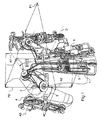
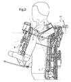
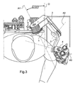
図に示される肩機構はまず、第一の要素1又は背中部品を備え、第一の要素は、ユーザによって直接装着され、ユーザの背中にわたって拡がる。第一の要素1は、第一の要素1に対して第一の蝶番軸線A1回りに蝶着される第二の要素2を有する。本発明によれば、蝶番軸線A1は以下のように傾けられる。肩の中心を含む水平平面をP1とし、ユーザに対して前から後ろに延びる、平面P内の縦方向をDとする。次いで、蝶番軸線A1は、平面P1内において25度である角度αの位置にあり(この角度は、図3の等身大の図により理解できる。)、鉛直平面P2の水平に対して25度である角度βの位置にある(この角度は、図2の等身大の図により理解できる。)。
The shoulder mechanism shown in the figure first comprises a first element 1 or back part, which is worn directly by the user and extends over the user's back. The first element 1 has a
次いで、第三の要素3は、第二の要素に対して第二の蝶番軸線A2回りに蝶着される。第二の蝶番軸線は、第一の蝶番軸線A1に対して75度である角度γに向けられる。 The third element 3 is then hinged around the second hinge axis A2 with respect to the second element. The second hinge axis is oriented at an angle γ that is 75 degrees with respect to the first hinge axis A1.
最後に、装具の上腕部4は第三の要素に対して第三の蝶番軸線A3回りに蝶着され、第三の軸線A3は、第二の蝶番軸線A2に対して80度である角度で延びる。したがって、本発明の必須の特徴によれば、3つの蝶番軸線は、基準の直交しないフレームを画定する方向に延びる。 Finally, the upper arm 4 of the brace is hinged about the third hinge axis A3 with respect to the third element, and the third axis A3 is at an angle of 80 degrees with respect to the second hinge axis A2. Extend. Thus, according to an essential feature of the invention, the three hinge axes extend in a direction that defines a reference non-orthogonal frame.
3つの蝶番は、この例では、ピボット軸受を用いて作成される接続体を枢動させることによって具現化される。 Three hinges are embodied in this example by pivoting a connection made using a pivot bearing.
3つの蝶番軸線は、ユーザの肩部の推定された中心の箇所で交わる。しかしながら、この配置は、本発明の場合では必須ではなく、3つの蝶番軸線がこれらと厳密には交わることなく推定された中心の付近に単に収束することができる。 The three hinge axes meet at the estimated center location of the user's shoulder. However, this arrangement is not essential in the case of the present invention and the three hinge axes can simply converge near the estimated center without strictly intersecting them.
こうした構成により、上腕部が、円形の滑り面を用いることなく広範囲に移動することができる。 With such a configuration, the upper arm can move over a wide range without using a circular sliding surface.
好ましくは、第一及び第二の蝶番軸線の回りでの枢動作用における自由度のある動作は、背中部品1に取り付けられると共に多様な蝶番を用いて同心状に取り付けられた滑車が必要とする受容された又は偏向したこれらのケーブルを有するケーブルアクチュエータ5の補助によって行われる。 Preferably, the freedom of movement for pivoting about the first and second hinge axes requires a pulley attached to the back piece 1 and concentrically mounted using various hinges. This is done with the aid of a cable actuator 5 having these cables received or deflected.
本発明は当然に上記記載に限定されるものではない。具体的には、角度の値は、指示によって付与されるものであり、ユーザの形態に適したものであってもよい。示された値の±10度の範囲は、ほとんどの肩部の形態に適応するのに十分である。 Naturally, the present invention is not limited to the above description. Specifically, the value of the angle is given by an instruction and may be suitable for the user's form. A range of ± 10 degrees of the indicated value is sufficient to accommodate most shoulder configurations.
Claims (6)
・ ユーザに対して固定された第一の要素(1)と、
・ 第一の要素に対して第一の蝶番軸線(A1)回りに蝶着された第二の要素(2)と、
・ 第二の要素に対して第二の蝶番軸線(A2)回りに蝶着された第三の要素(3)と、
・ 第三の要素に対して第三の蝶番軸線(A3)回りに蝶着された上腕部(4)と、
を一連の形で具備する、
装具のための肩機構において、
蝶番軸線(A1,A2,A3)が、直交しない基準のフレームを画定する方向に延びる、
装具のための肩機構。 A shoulder mechanism for a brace,
A first element (1) fixed to the user;
A second element (2) hinged about the first hinge axis (A1) relative to the first element;
A third element (3) hinged about the second hinge axis (A2) relative to the second element;
An upper arm (4) hinged around a third hinge axis (A3) with respect to the third element;
In a series of forms,
In the shoulder mechanism for the brace,
The hinge axes (A1, A2, A3) extend in a direction defining a non-orthogonal reference frame;
Shoulder mechanism for the brace.
装具のための肩機構。 The hinge axes (A1, A2, A3) are tilted with respect to the vertical and horizontal directions when the user's arm is at rest,
Shoulder mechanism for the brace.
請求項2に記載の装具のための肩機構。 The first hinge axis (A1) extends at an angle (α) in the range of ± 10 degrees around an angle of 25 degrees with respect to the horizontal plane including the estimated center of the shoulder and is perpendicular to the horizontal Extends at an angle (β) in the range of ± 10 degrees in the direction of the plane,
A shoulder mechanism for the brace of claim 2.
請求項3に記載の装具のための肩機構。 A second hinge axis (A2) extends at an angle (γ) within a range of ± 10 degrees around a 75 degree angle;
A shoulder mechanism for the brace of claim 3.
請求項4に記載の装具のための肩機構。 A third hinge axis (A3) extends at an angle in the range of ± 10 degrees around an 80 degree angle;
A shoulder mechanism for the brace of claim 4.
請求項1〜5のいずれか1項に記載の装具のための肩機構。 The hinge is embodied by a pivot bearing,
A shoulder mechanism for a brace according to any one of claims 1-5.
Applications Claiming Priority (3)
| Application Number | Priority Date | Filing Date | Title |
|---|---|---|---|
| FR0904313A FR2949669B1 (en) | 2009-09-09 | 2009-09-09 | SHOULDER MECHANISM FOR ORTHESIS |
| FR0904313 | 2009-09-09 | ||
| PCT/EP2010/005452 WO2011029564A2 (en) | 2009-09-09 | 2010-09-06 | Shoulder mechanism for orthesis |
Publications (1)
| Publication Number | Publication Date |
|---|---|
| JP2013503665A true JP2013503665A (en) | 2013-02-04 |
Family
ID=42034618
Family Applications (1)
| Application Number | Title | Priority Date | Filing Date |
|---|---|---|---|
| JP2012527243A Pending JP2013503665A (en) | 2009-09-09 | 2010-09-06 | Shoulder mechanism for orthosis |
Country Status (5)
| Country | Link |
|---|---|
| US (1) | US9592145B2 (en) |
| EP (1) | EP2475338B1 (en) |
| JP (1) | JP2013503665A (en) |
| FR (1) | FR2949669B1 (en) |
| WO (1) | WO2011029564A2 (en) |
Cited By (3)
| Publication number | Priority date | Publication date | Assignee | Title |
|---|---|---|---|---|
| JP2017024086A (en) * | 2015-07-15 | 2017-02-02 | 株式会社キトー | Work assist device |
| WO2017170619A1 (en) * | 2016-03-30 | 2017-10-05 | 国立大学法人 香川大学 | Muscle-power support device |
| JP2021500242A (en) * | 2017-10-24 | 2021-01-07 | サフラン・エレクトロニクス・アンド・デファンス | Exoskeleton structure adapted to the shoulder |
Families Citing this family (26)
| Publication number | Priority date | Publication date | Assignee | Title |
|---|---|---|---|---|
| EP2665449B1 (en) * | 2011-01-18 | 2017-11-15 | Levitate Technologies, Inc. | Adaptive arm support systems and methods for use |
| ES2370895B2 (en) * | 2011-08-31 | 2012-05-08 | Universidad Politécnica de Madrid | Wearable robotic exoskeleton for human arm. |
| FR2991224B1 (en) * | 2012-06-04 | 2014-06-27 | Commissariat Energie Atomique | ARM OF EXOSQUELET WITH ACTUATOR |
| ITRM20120482A1 (en) * | 2012-10-09 | 2014-04-10 | Uni Campus Bio Medico Di Rom A | ROBOTIC DEVICE FOR ASSISTANCE AND REHABILITATION OF LOWER LIMBS. |
| CN103831832B (en) * | 2012-11-26 | 2016-04-06 | 苏茂 | Bilateral force feedback is from hand arm control device |
| EP3395506B2 (en) * | 2012-12-11 | 2023-04-26 | Levitate Technologies, Inc. | Adaptive arm support systems and methods for use |
| GB201305984D0 (en) * | 2013-04-03 | 2013-05-15 | Moog Bv | Mechanical linkage |
| WO2015099858A2 (en) | 2013-09-30 | 2015-07-02 | Board Of Regents, The University Of Texas System | Upper-body robotic exoskeleton |
| KR101510009B1 (en) | 2013-12-17 | 2015-04-07 | 현대자동차주식회사 | Apparatus for driving wearable robot |
| KR101510019B1 (en) * | 2013-12-18 | 2015-04-07 | 현대자동차주식회사 | Wire-driven robot |
| DE102014009028A1 (en) * | 2014-06-24 | 2015-12-24 | Otto Bock Healthcare Gmbh | Leg orthosis and orthosis |
| EP3257493A4 (en) * | 2015-02-11 | 2018-10-17 | Korea University of Technology and Education Industry-University Corporation Foundation | Upper-limb exercising device of a type worn on the body |
| US10639785B2 (en) | 2015-05-18 | 2020-05-05 | The Regents Of The University Of California | Variable force generators for arm supporting exoskeletons |
| US10569413B2 (en) | 2015-12-22 | 2020-02-25 | Ekso Bionics, Inc. | Exoskeleton and method of providing an assistive torque to an arm of a wearer |
| US10058994B2 (en) | 2015-12-22 | 2018-08-28 | Ekso Bionics, Inc. | Exoskeleton and method of providing an assistive torque to an arm of a wearer |
| US10814473B2 (en) * | 2016-07-26 | 2020-10-27 | Arizona Board Of Regents On Behalf Of Arizona State University | Mechanism for alleviating the effects of joint misalignment between users and wearable robots |
| DE102016121202A1 (en) * | 2016-11-07 | 2018-05-09 | Otto Bock Healthcare Gmbh | Device for supporting an arm |
| US10918559B2 (en) | 2017-04-25 | 2021-02-16 | Ossur Iceland Ehf | Interface system in an exoskeleton |
| DE102017112436B4 (en) | 2017-06-06 | 2019-05-29 | Ottobock Se & Co. Kgaa | Device for supporting at least one arm of a user |
| WO2019067835A1 (en) | 2017-09-28 | 2019-04-04 | Ossur Iceland Ehf | Body interface |
| GB2567010A (en) | 2017-10-02 | 2019-04-03 | Univ Strathclyde | Apparatus for the rehabilitation, assistance and/or augmentation of arm strength in a user |
| US10966893B2 (en) * | 2018-03-23 | 2021-04-06 | Hiwin Technologies Corp. | Exoskeleton apparatus for limb rehabilitation |
| USD876654S1 (en) | 2018-04-24 | 2020-02-25 | Ossur Iceland Ehf | Posterior strut |
| CN108814902B (en) * | 2018-06-29 | 2020-01-10 | 华中科技大学 | Upper limb exoskeleton rehabilitation device capable of matching human-computer motion and exchanging on opposite side |
| KR102603041B1 (en) * | 2018-12-12 | 2023-11-16 | 현대자동차주식회사 | Wearable apparatus for assisting muscular strength |
| CN112476477B (en) * | 2020-11-12 | 2022-04-19 | 中国科学技术大学 | Rope-driven three-degree-of-freedom offset joint |
Citations (7)
| Publication number | Priority date | Publication date | Assignee | Title |
|---|---|---|---|---|
| US4669451A (en) * | 1983-12-15 | 1987-06-02 | Ernst Knoll | Apparatus for postoperative and other exercising of elbow and shoulder joints |
| WO1995032842A2 (en) * | 1994-05-19 | 1995-12-07 | Exos, Inc. | Sensory feedback exoskeleton armmaster |
| DE19940603A1 (en) * | 1999-08-27 | 2001-04-19 | Christian Schaefer | Manipulator has joint section with rotary single joint or chain of single joints with rotational axes |
| US20070225620A1 (en) * | 2006-03-23 | 2007-09-27 | Carignan Craig R | Portable Arm Exoskeleton for Shoulder Rehabilitation |
| US20080009771A1 (en) * | 2006-03-29 | 2008-01-10 | Joel Perry | Exoskeleton |
| WO2008031023A2 (en) * | 2006-09-07 | 2008-03-13 | Ohio University | Haptic exoskeleton |
| FR2917323A1 (en) * | 2007-06-12 | 2008-12-19 | Commissariat Energie Atomique | FRONT ROTATION MECHANISM AND ORTHESIS COMPRISING SUCH A MECHANISM |
Family Cites Families (12)
| Publication number | Priority date | Publication date | Assignee | Title |
|---|---|---|---|---|
| US3449769A (en) * | 1966-06-27 | 1969-06-17 | Cornell Aeronautical Labor Inc | Powered exoskeletal apparatus for amplifying human strength in response to normal body movements |
| US5407420A (en) * | 1992-11-12 | 1995-04-18 | Smith & Nephew Donjoy, Inc. | Fully adjustable shoulder brace |
| US5417643A (en) * | 1993-10-27 | 1995-05-23 | Danninger Medical Technology, Inc. | Continuous passive motion exercise device |
| WO1997002520A1 (en) * | 1995-06-30 | 1997-01-23 | Ross-Hime Designs, Inc. | Robotic manipulator |
| KR100299210B1 (en) * | 1999-03-12 | 2001-09-22 | 박호군 | Master device having force reflective function |
| US6155993A (en) * | 1999-03-31 | 2000-12-05 | Queen's University At Kingston | Kinesiological instrument for limb movements |
| US20030115954A1 (en) * | 2001-12-07 | 2003-06-26 | Vladimir Zemlyakov | Upper extremity exoskeleton structure and method |
| EP1581368A1 (en) * | 2002-12-31 | 2005-10-05 | Fabio Salsedo | Ekoskeleton interface apparatus |
| ATE468090T1 (en) * | 2006-10-12 | 2010-06-15 | Univ Twente | ORTHOSE |
| CA2684971C (en) * | 2007-05-01 | 2016-07-26 | Queen's University At Kingston | Robotic exoskeleton for limb movement |
| TWI354550B (en) * | 2008-05-09 | 2011-12-21 | Univ Nat Taiwan | Rehabilitating and training device and controlling |
| KR101065420B1 (en) * | 2008-12-16 | 2011-09-16 | 한양대학교 산학협력단 | Wearable Robotic System for the Rehabilitation Training of upper limbs |
-
2009
- 2009-09-09 FR FR0904313A patent/FR2949669B1/en active Active
-
2010
- 2010-09-06 WO PCT/EP2010/005452 patent/WO2011029564A2/en active Application Filing
- 2010-09-06 JP JP2012527243A patent/JP2013503665A/en active Pending
- 2010-09-06 US US13/395,184 patent/US9592145B2/en active Active
- 2010-09-06 EP EP10754686.3A patent/EP2475338B1/en active Active
Patent Citations (8)
| Publication number | Priority date | Publication date | Assignee | Title |
|---|---|---|---|---|
| US4669451A (en) * | 1983-12-15 | 1987-06-02 | Ernst Knoll | Apparatus for postoperative and other exercising of elbow and shoulder joints |
| WO1995032842A2 (en) * | 1994-05-19 | 1995-12-07 | Exos, Inc. | Sensory feedback exoskeleton armmaster |
| DE19940603A1 (en) * | 1999-08-27 | 2001-04-19 | Christian Schaefer | Manipulator has joint section with rotary single joint or chain of single joints with rotational axes |
| US20070225620A1 (en) * | 2006-03-23 | 2007-09-27 | Carignan Craig R | Portable Arm Exoskeleton for Shoulder Rehabilitation |
| US20080009771A1 (en) * | 2006-03-29 | 2008-01-10 | Joel Perry | Exoskeleton |
| WO2008031023A2 (en) * | 2006-09-07 | 2008-03-13 | Ohio University | Haptic exoskeleton |
| FR2917323A1 (en) * | 2007-06-12 | 2008-12-19 | Commissariat Energie Atomique | FRONT ROTATION MECHANISM AND ORTHESIS COMPRISING SUCH A MECHANISM |
| JP2010529874A (en) * | 2007-06-12 | 2010-09-02 | コミッサリア ア レネルジー アトミーク エ オ ゼネルジ ザルタナテイヴ | Forearm rotation mechanism and straightener including the mechanism |
Cited By (5)
| Publication number | Priority date | Publication date | Assignee | Title |
|---|---|---|---|---|
| JP2017024086A (en) * | 2015-07-15 | 2017-02-02 | 株式会社キトー | Work assist device |
| WO2017170619A1 (en) * | 2016-03-30 | 2017-10-05 | 国立大学法人 香川大学 | Muscle-power support device |
| JPWO2017170619A1 (en) * | 2016-03-30 | 2019-02-07 | 国立大学法人 香川大学 | Strength assist device |
| JP2021500242A (en) * | 2017-10-24 | 2021-01-07 | サフラン・エレクトロニクス・アンド・デファンス | Exoskeleton structure adapted to the shoulder |
| JP7036916B2 (en) | 2017-10-24 | 2022-03-15 | サフラン・エレクトロニクス・アンド・デファンス | Exoskeleton structure adapted to the shoulder |
Also Published As
| Publication number | Publication date |
|---|---|
| EP2475338A2 (en) | 2012-07-18 |
| US20120172769A1 (en) | 2012-07-05 |
| WO2011029564A2 (en) | 2011-03-17 |
| EP2475338B1 (en) | 2016-07-13 |
| US9592145B2 (en) | 2017-03-14 |
| FR2949669A1 (en) | 2011-03-11 |
| WO2011029564A3 (en) | 2011-06-16 |
| FR2949669B1 (en) | 2011-11-18 |
Similar Documents
| Publication | Publication Date | Title |
|---|---|---|
| JP2013503665A (en) | Shoulder mechanism for orthosis | |
| US10816135B2 (en) | Heavy capacity arm support systems | |
| JP6174560B2 (en) | Arm structure for intraoral X-ray apparatus | |
| JP2009050987A (en) | Robot and its control method | |
| JP2004236323A (en) | Headphone | |
| JP2004097819A5 (en) | ||
| KR20170039670A (en) | Movement assistance device | |
| JP2004236324A (en) | Headphone | |
| JP6981788B2 (en) | Operation assist device | |
| JP2012501497A5 (en) | ||
| TW200703173A (en) | Support for multiple displays | |
| JP2004080679A5 (en) | ||
| KR101500200B1 (en) | Load supporting apparatus of robot | |
| EP1207022A1 (en) | Arm for a humanoid robot | |
| JP2014508616A (en) | Arm of arm structure for intraoral X-ray apparatus | |
| JP2021508608A (en) | Safety protection of robot joints | |
| ATE405231T1 (en) | KNEE SUPPORT HINGES WITH ADAPTIVE MOVEMENT | |
| CN105817793A (en) | Adjustable cantilever bracket for intelligent welding robot | |
| JP7180864B2 (en) | Arm movement assist device | |
| JP3905499B2 (en) | Mannequin arm structure | |
| KR20070097651A (en) | Brace with universal elbow-hinged | |
| JP5086607B2 (en) | Armrest built-in table device | |
| KR200422639Y1 (en) | Balance arm for dental treatment unit | |
| JP2010228708A (en) | Hinge structure for engine hood of vehicle | |
| JP2011116349A (en) | Tool for painting door |
Legal Events
| Date | Code | Title | Description |
|---|---|---|---|
| A131 | Notification of reasons for refusal |
Free format text: JAPANESE INTERMEDIATE CODE: A131 Effective date: 20130423 |
|
| A601 | Written request for extension of time |
Free format text: JAPANESE INTERMEDIATE CODE: A601 Effective date: 20130722 |
|
| A602 | Written permission of extension of time |
Free format text: JAPANESE INTERMEDIATE CODE: A602 Effective date: 20130729 |
|
| A521 | Written amendment |
Free format text: JAPANESE INTERMEDIATE CODE: A523 Effective date: 20131023 |
|
| A02 | Decision of refusal |
Free format text: JAPANESE INTERMEDIATE CODE: A02 Effective date: 20131210 |
|
| A521 | Written amendment |
Free format text: JAPANESE INTERMEDIATE CODE: A821 Effective date: 20140411 |