JP2013500659A - Method, apparatus and computer readable recording medium for reducing self-interference at a terminal in a communication system. - Google Patents
Method, apparatus and computer readable recording medium for reducing self-interference at a terminal in a communication system. Download PDFInfo
- Publication number
- JP2013500659A JP2013500659A JP2012522130A JP2012522130A JP2013500659A JP 2013500659 A JP2013500659 A JP 2013500659A JP 2012522130 A JP2012522130 A JP 2012522130A JP 2012522130 A JP2012522130 A JP 2012522130A JP 2013500659 A JP2013500659 A JP 2013500659A
- Authority
- JP
- Japan
- Prior art keywords
- uplink
- user terminal
- bandwidth
- downlink resource
- resource allocation
- Prior art date
- Legal status (The legal status is an assumption and is not a legal conclusion. Google has not performed a legal analysis and makes no representation as to the accuracy of the status listed.)
- Pending
Links
Images


Classifications
-
- H—ELECTRICITY
- H04—ELECTRIC COMMUNICATION TECHNIQUE
- H04W—WIRELESS COMMUNICATION NETWORKS
- H04W72/00—Local resource management
- H04W72/04—Wireless resource allocation
- H04W72/044—Wireless resource allocation based on the type of the allocated resource
- H04W72/0453—Resources in frequency domain, e.g. a carrier in FDMA
-
- H—ELECTRICITY
- H04—ELECTRIC COMMUNICATION TECHNIQUE
- H04W—WIRELESS COMMUNICATION NETWORKS
- H04W72/00—Local resource management
- H04W72/50—Allocation or scheduling criteria for wireless resources
- H04W72/54—Allocation or scheduling criteria for wireless resources based on quality criteria
- H04W72/541—Allocation or scheduling criteria for wireless resources based on quality criteria using the level of interference
Abstract
周波数分割復信、直交周波数分割多重通信システムにおいて資源を割り当てる方法及び装置であって、ユーザ端末がサブフレームにおいてアップリンク送信をスケジュールされるときに、ユーザ端末の自己誘発干渉に対する耐性へ影響するパラメータに基づいて、ユーザ端末へのダウンリンクのサブフレームにおける数、周波数配置、符号化方式を取り入れる方法及び装置。
【選択図】 図5A method and apparatus for allocating resources in a frequency division duplex, orthogonal frequency division multiplex communication system, with parameters affecting the resistance of the user terminal against self-induced interference when the user terminal is scheduled for uplink transmission in a subframe Based on the number, frequency allocation and coding scheme in downlink subframes to user terminals.
[Selection] Figure 5
Description
本発明は、無線通信システムに関し、特にはそのようなシステムにおいてスケジューリングされた送信を行うことに関する。 The present invention relates to wireless communication systems, and more particularly to performing scheduled transmissions in such systems.
ロングタームエボリューション(LTE)や高速パケットアクセス(HSPA)のようなやがて来るセルラー無線通信システムにおいて、スループット或いはデータレートの最大値は過去のシステムよりも高いものになろう。高いスループットは概してより広いシステムチャンネル帯域幅を要求する。 In an upcoming cellular radio communication system such as Long Term Evolution (LTE) or High Speed Packet Access (HSPA), the maximum throughput or data rate will be higher than in past systems. High throughput generally requires a wider system channel bandwidth.
LTEやHSPAは第3世代通信システムと呼ばれることがあり、第3世代パートナシッププロジェクト(3GPP)が現在標準化をすすめている。LTEの仕様は現在のワイドバンド符号分割多重アクセス(WCDMA)仕様の発展として見ることができる。進歩したIMT通信システムはLTE、HSPAのインターネットプロトコル(IP)マルチメディアサブシステム(IMS)あるいはIMSマルチメディア電話通信(IMT)のための他の通信システムを使用する。進歩したIMTシステム(第4世代移動体通信システム)は帯域が100メガヘルツ(MHz)以上とすることが検討されている。3GPPはLTE、HSPA、WCDMA、IMTシステムの仕様、他の種類のセルラー無線通信システムを規格化した仕様を公開する。 LTE and HSPA are sometimes referred to as third generation communication systems, and the third generation partnership project (3GPP) is currently standardizing. The LTE specification can be viewed as an evolution of the current wideband code division multiple access (WCDMA) specification. Advanced IMT communication systems use LTE, HSPA Internet Protocol (IP) Multimedia Subsystem (IMS) or other communication systems for IMS Multimedia Telephony (IMT). An advanced IMT system (fourth generation mobile communication system) is considered to have a bandwidth of 100 megahertz (MHz) or higher. 3GPP publishes specifications that standardize LTE, HSPA, WCDMA, IMT systems, and other types of cellular radio communication systems.
LTEシステムは多重アクセス技術として、システムのノードからユーザ端末(UE)へのダウンリンクに直交周波数分割多重(OFDMと呼ばれる。)を使用する。LTEシステムのチャンネル帯域幅は約1.4MHzから20MHzであり、最大帯域幅においてスループットは100メガビット/秒をサポートする。LTEダウンリンクに定義された物理チャンネルの一つのタイプは物理ダウンリンク共用チャンネル(PDSCH)であり、より上位のLTEプロトコルスタックのレイヤからの情報を伝送し、1または複数の特定のトランスポートチャンネルに配置される。制御情報は物理アップリンク制御チャンネル(PUCCH)と物理ダウンリンク制御チャンネル(PDCCH)によって伝送される。LTEチャンネルについては非特許文献1や他の仕様に記載されている。
The LTE system uses orthogonal frequency division multiplexing (referred to as OFDM) in the downlink from a node of the system to a user terminal (UE) as a multiple access technique. The channel bandwidth of the LTE system is about 1.4 MHz to 20 MHz and the throughput supports 100 megabits / second at maximum bandwidth. One type of physical channel defined for LTE downlink is the Physical Downlink Shared Channel (PDSCH), which carries information from higher layers of the LTE protocol stack to one or more specific transport channels. Be placed. Control information is transmitted through a physical uplink control channel (PUCCH) and a physical downlink control channel (PDCCH). The LTE channel is described in
LTEのようなOFDM通信システムにおいては、ダウンリンクで送信されるデータストリームはいくつかのナローバンドのサブキャリアに分割して平行して送信される。一般に特定のユーザ端末のためのリソースブロック(RB)は、特定の期間使用される特定数の特定のサブキャリアである。リソースブロックはリソースエレメント(RE)から構成されており、それぞれは短い時間だけ使用される特定のサブキャリアである。異なるサブキャリアのグループは違う時間に違うユーザに使用される。各サブキャリアはナローバンドであり、各サブキャリアは大部分がフラットフェージング(flat fading)するので、ユーザ端末にとって各サブキャリアを復調することが簡単である。 In an OFDM communication system such as LTE, a data stream transmitted in the downlink is divided into several narrowband subcarriers and transmitted in parallel. In general, a resource block (RB) for a specific user terminal is a specific number of specific subcarriers used for a specific period. A resource block is composed of resource elements (RE), each of which is a specific subcarrier used only for a short time. Different subcarrier groups are used for different users at different times. Since each subcarrier is a narrow band and most of each subcarrier undergoes flat fading, it is easy for the user terminal to demodulate each subcarrier.
多くの現代的な通信システムと同じく、LTEシステムでのダウンリンク送信は10ミリ秒間隔のフレームから構成され、各フレームは20の連続したタイムスロットを有し、サブフレームは2つの連続したタイムスロットを有する。OFDM通信システムは例えばB.リンドホフ他による特許文献1に記載されている。
As with many modern communication systems, downlink transmissions in LTE systems consist of frames that are 10 ms apart, each frame has 20 consecutive time slots, and a subframe is two consecutive time slots. Have An OFDM communication system is, for example, B.I.
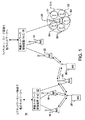
図1は典型的なセルラー通信システム10を示す。無線ネットワーク制御装置(RNC)12、14は、例えば無線アクセスベアラセットアップや基地局間ハンドオーバーなどを含むいろいろな無線ネットワーク機能を制御する。一般にそれぞれのRNCは適切な基地局(BS)を経由してダウンリンク(順方向)やアップリンクチャンネル(UL、逆方向)を通じ、お互いに通信する移動局、移動電話、あるいは他の遠隔端末のようなユーザ端末と呼を管理する。図1においてRNC12は基地局16、18、20と接続されていることが示され、RNC14は基地局22、24、26と接続されていることが示される。
FIG. 1 shows a typical
それぞれの基地局、LTE用語でいうeNodeBは1又は複数のセルに分割された地理的な地域を受け持つ。5つのアンテナセクタ(antenna sector)S1−S5を有する基地局26が図1に示され、基地局26はセルを形成しているといえ、ある基地局からの信号によりサービスされる一つのセクタ又は他の地域はセルと呼ばれる。加えて、基地局はユーザ端末へ信号を送信するために複数のアンテナを使用してもよい。基地局は一般的には専用電話線、光ファイバやマイクロウェーブ回線などにより対応するRNCに接続されている。RNC12、14は1又は複数の移動通信交換局(不図示)やパケット無線サービスノード(不図示)のようなコアネットワークノードを介して公衆回線電話網(PSTN)やインターネットのような外部ネットワークに接続される。
Each base station, eNodeB in LTE terminology, is responsible for a geographical area divided into one or more cells. A
図1に示される複数機能の配置はLTEや他の通信システムへの変更が可能であることが理解されるだろう。例えば、RNC12、14の機能はeNodeB22、24、26に移動可能であり、他の機能もネットワークの他のノードへ移動することができる。基地局がセル/セクタ/エリアへ情報を送信するための複数の送信アンテナを使用でき、異なる送信アンテナは異なるパイロットシグナルを別々に送信することができることも理解されるだろう。
It will be understood that the multiple function arrangement shown in FIG. 1 can be modified to LTE or other communication systems. For example, the functions of the
高速で効率的なセルサーチと受信信号の測定はユーザ端末がサービングセル(serving cell)と呼ばれる適切なセルを捕捉して接続を維持するために重要である。定期的にユーザ端末はサービングセルを含む、検出したそれぞれのセルの受信信号強度と信号品質を測定し、新しいサービングセルが選択されるべきかどうか判定する。新しいセルは現在のセルと同じ周波数上でも違う周波数上でも存在できる。ユーザ端末は、セルサーチ手順の結果検出したサービングセルと近傍のセルのeNodeBによって送信される基準シンボル(RS)の平均ユーザ端末受信信号電力として定義される基準信号受信電力(RSRP)を測定する。セルサーチ手順は例えば、非特許文献2のセクション5.2に記載されている。eNodeBはユーザ端末個々に制御命令を送信することによってユーザ端末の送信電力レベルを制御し、ユーザ端末は随時、自局が把握したチャンネル品質や他の信号パラメータを1又は複数のeNodeBへ送信することができる。
Fast and efficient cell search and received signal measurement are important for a user terminal to acquire an appropriate cell called a serving cell and maintain a connection. Periodically, the user terminal measures the received signal strength and signal quality of each detected cell, including the serving cell, to determine whether a new serving cell should be selected. A new cell can exist on the same frequency as the current cell or on a different frequency. The user terminal measures a reference signal received power (RSRP) defined as an average user terminal received signal power of a reference symbol (RS) transmitted by the serving cell detected as a result of the cell search procedure and an eNodeB of a neighboring cell. The cell search procedure is described in Section 5.2 of
図2はLTEシステムのサブフレームでのリソースブロックのサブキャリアの配置を示している。図2に示される周波数範囲は27サブキャリアを含んでおり、その内の9サブキャリアだけが明示されている。図2において破線で示されるリソースブロックは、それぞれが15キロヘルツ(kHz)離れており周波数において180kHz,時間において0.5msあるいは1タイムスロットの間を占有する12サブキャリアを含んでいる。LTEシステムにおいてリソースブロックは15kHzのサブキャリア帯域幅を持つ12サブキャリアか7.5kHzのサブキャリア帯域幅を持つ24サブキャリアの幅を持ち、各スロットの期間は0.5msにわたる。図2は各タイムスロットが7OFDMシンボル又はリソースエレメントを含み、各シンボルは短い(通常の)サイクリックプリフィックス(cyclic prefix)を有するものを示すが、その代わりにタイムスロットにおいて長い(延長された)サイクリックプリフィックスを持つ6OFDMシンボルを使うことができる。 FIG. 2 shows an arrangement of subcarriers of resource blocks in a subframe of the LTE system. The frequency range shown in FIG. 2 includes 27 subcarriers, of which only 9 subcarriers are specified. The resource blocks indicated by the broken lines in FIG. 2 include 12 subcarriers that are 15 kHz apart and occupy 180 kHz in frequency, 0.5 ms in time, or one time slot. In the LTE system, the resource block has a width of 12 subcarriers with a subcarrier bandwidth of 15 kHz or 24 subcarriers with a subcarrier bandwidth of 7.5 kHz, and the duration of each slot spans 0.5 ms. FIG. 2 shows each time slot containing 7 OFDM symbols or resource elements, each symbol having a short (normal) cyclic prefix, but instead a long (extended) cycle in the time slot. 6 OFDM symbols with a click prefix can be used.
eNodeBの第1送信(TX)アンテナにより送信される基準シンボルはRで示され、eNodeBの第2TXアンテナにより送信される可能性のある基準シンボルはSで示される。図2において基準シンボルは、各スロットのOFDMシンボル0とOFDMシンボル4(シンボルは短いサイクリックプリフィックスを有する為。)において毎6番目のサブキャリアで送信されるように記載されている。さらに、図2においてシンボル4の基準シンボルは、スロットの最初のOFDMシンボルであるOFDMシンボル0の基準シンボルに比較して3サブキャリアだけオフセットされている。
A reference symbol transmitted by the first transmit (TX) antenna of the eNodeB is indicated by R, and a reference symbol that may be transmitted by the second TX antenna of the eNodeB is indicated by S. In FIG. 2, the reference symbol is described so that it is transmitted on every sixth subcarrier in
基準信号の近くに、WCDMAに類似する階層型セルサーチ手法でLTEにおいて予め決められた同期信号が送信され、同期回復とセルグループ識別が異なる同期チャンネル(SCH)信号から得られる。優先同期チャンネル(primary synchronization channel:P−SCH)とセカンダリ同期チャンネル(secondary synchronization cahnnel:S−SCH)は非特許文献1のセクション6.11に定義された構造で定義される。例えば、P−SCHとS−SCH信号は特定のタイムスロットで特定のサブキャリアによって送信される。LTEシステムではeNodeBは2つの同期信号、優先同期信号(PSS)とセコンダリ同期信号(SSS)を送信する。優先及びセコンダリ同期信号はR.バルデマール他による特許文献2に記載されている。図2はOFDMシンボル5、6(短いサイクリックプリフィックスと周波数分割(FDD)で動作すると仮定して。)のSSSとPSSを示している。最新のLTEシステムではPSSとSSSはサブフレーム0と5における中央の6個のリソースブロックによって送信される。
A synchronization signal predetermined in LTE is transmitted near the reference signal in a hierarchical cell search method similar to WCDMA, and synchronization recovery and cell group identification are obtained from different synchronization channel (SCH) signals. A primary synchronization channel (P-SCH) and a secondary synchronization channel (S-SCH) are defined in the structure defined in Section 6.11 of
LTEのようなシステムではFDDに関して、ダウンリンクとアップリンクのデータ送信は独立してスケジュールされ、ある時はダウンリンク送信のみ、他の時はアップリンク送信のみ、またさらにほかの時はダウンリンクとアップリンク送信が同時にある。アップリンク−ダウンリンクのフレームタイミングは非特許文献1のセクション8に具体的に記載されている。
In systems like LTE, for FDD, downlink and uplink data transmissions are scheduled independently, sometimes only downlink transmissions, at other times only uplink transmissions, and at other times downlink and There is an uplink transmission at the same time. The uplink-downlink frame timing is specifically described in Section 8 of
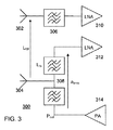
LTE等のユーザ端末は1つの送信と2つの受信アンテナを使うと言われており、これは普通はユーザ端末が物理的に2つのアンテナを持つ場合である。その結果、FDDシステム用のユーザ端末300の一部分のブロック図である図3に示されるように送信パスと受信パスの内の一つは同じアンテナを共用する。ユーザ端末300は第1アンテナ302と第2アンテナ304,バンドパスフィルタ306、デュプレックスバンドパスフィルタ308、2つのローノイズアンプ(LNA)310,312、パワーアンプ(PA)314を含む。図に示されるようにユーザ端末300は、アンテナ302,フィルタ306、LNA310を含む第1のパスとアンテナ304、デュプレックスフィルタ308、LNA312を含む第2のパスとの2つの受信パスを有するダイバシティ受信機を有する。ユーザ端末300はさらにPA314、デュプレックスフィルタ308、アンテナ304を含む送信パスを含む。受信機に要求される最低限の基準感度は非特許文献3のセクション7.3に詳しく記載されており、ここには受信機のノイズファクターについて基本的に詳しく記載している。
User terminals such as LTE are said to use one transmission and two reception antennas, which is usually the case when the user terminal has two physical antennas. As a result, one of the transmission path and the reception path shares the same antenna as shown in FIG. 3 which is a block diagram of a part of the
ユーザ端末300において、ユーザ端末がダウンリンクとアップリンクデータについて同じサブフレームにスケジュールされたときのユーザ端末におけるアップリンク(送信)とダウンリンク(受信)パスの間の漏れは復調されたダウンリンクサブキャリアのスペクトルにおいて周波数ゼロ(d.c)の周囲のノイズ成分を生じる。漏れは例えば、アンテナ302と304の間の誘導性結合Lcplとデュプレックスフィルタ308の1部分の間の誘導性結合Lrxと抵抗性結合atx−rxにより発生し得る。一般にノイズのスペクトルは周波数ゼロの周囲で対称形でありアップリンク送信の帯域幅の2倍の帯域幅を有する。その結果、漏れはサブキャリアに影響してノイズフロアを上昇させ、総合的なダウンリンクの復調能力を低下させる。このようなノイズ成分は主に2次の非線形の結果に起因して、漏れにより誘起された干渉(leakage−induced interference)を受信信号に生じる。
In
RFまたはベースバンド成分における2次の非線形性は(変調された)送信漏れ信号を2乗し、ダイレクトコンバージョン受信機の受信帯域内においてd.c.及び変調された成分をd.c.周囲に発生する。変調された部分は2乗(すなわち、周波数領域での畳み込み)により2倍の帯域となって現れる。強力な送信信号の漏れがアップリンクミキサの入力ポートと結合してそれ自身と掛け合わされてセルフミキシングのような別の影響も起き、受信帯域幅内のd.c.の周囲に送信帯域幅の2倍の変調された信号を発生する。デュプレックスフィルタというものの目的は少なくとも受信パスのスペクトラムのインバンド部分に送信信号の顕著な漏洩を防ぐことであり、感度のよい受信機に必要なものとすることは容易ではない。 Second-order nonlinearities in the RF or baseband component square the (modulated) transmit leakage signal and d. c. And the modulated component d. c. Occurs around. The modulated portion appears as a doubled band due to the square (ie, convolution in the frequency domain). Strong transmit signal leakage combined with the input port of the uplink mixer and multiplied with itself also causes other effects such as self-mixing, d. c. A modulated signal of twice the transmission bandwidth is generated around. The purpose of the duplex filter is to prevent significant leakage of the transmission signal at least in the in-band part of the spectrum of the reception path, and it is not easy to make it necessary for a sensitive receiver.
ダウンリンクとアップリンクフレームのスケジューリングは、現在eNodeBが行っているが、ユーザ端末特有の干渉を考慮していないのでユーザ端末の復調能力を低下させている。そこで、ユーザ端末特有の干渉を考慮したダウンリンク/アップリンクスケジューリングをする方法と装置を改良する必要がある。 The scheduling of the downlink and uplink frames is currently performed by the eNodeB, but since the interference specific to the user terminal is not considered, the demodulation capability of the user terminal is reduced. Therefore, it is necessary to improve the method and apparatus for performing downlink / uplink scheduling in consideration of interference specific to the user terminal.
この発明は、周波数分割復信通信システムにおけるユーザ端末へのダウンリンクでの資源割当の方法をユーザ端末に提供する。 The present invention provides a user terminal with a method of resource allocation in the downlink to the user terminal in the frequency division duplex communication system.
本発明の方法は、ダウンリンク資源割当てのための少なくとも一つのパラメータを判定することを含み、少なくとも一つのパラメータは、アップリンク帯域幅割当て、アップリンク送信電力、ダウンリンク帯域幅割当て、初期の変調符号化方式(MCS(Modulation and Coding Scheme))の少なくとも一つであり、ダウンリンク資源割当を、スケジュールされたダウンリンクのリソースブロックが周波数的にはスケジュールされたアップリンク送信のゼロ周波数±バンド幅の帯域幅内に存在しないように判定された少なくとも一つのパラメータに基づいて行う。 The method of the present invention includes determining at least one parameter for downlink resource allocation, the at least one parameter being uplink bandwidth allocation, uplink transmit power, downlink bandwidth allocation, initial modulation. It is at least one of the coding schemes (MCS (Modulation and Coding Scheme)), and the downlink resource allocation is performed by the scheduled downlink resource block in terms of frequency. On the basis of at least one parameter determined not to exist within the bandwidth.
この発明は、ユーザ端末へのダウンリンクにおける資源割当のための周波数分割復信通信システムにおける装置も提供する。装置は、ダウンリンク資源割当のための少なくとも一つのパラメータを判定しかつダウンリンクの資源割当をスケジュールされたダウンリンクのリソースブロックが周波数的にはスケジュールされたアップリンク送信のゼロ周波数±バンド幅の帯域幅内に存在しないように判定した少なくとも一つのパラメータに基づいてする電子プロセッサを有する。少なくとも一つのパラメータは、アップリンク帯域幅割当て、アップリンク送信電力、ダウンリンク帯域幅割当て、初期の変調符号化方式を含む。 The present invention also provides an apparatus in a frequency division duplex communication system for resource allocation in the downlink to the user terminal. The apparatus determines at least one parameter for downlink resource allocation and the downlink resource block scheduled for downlink resource allocation is frequency-scheduled for uplink transmission zero frequency ± bandwidth Having an electronic processor based on at least one parameter determined not to be in bandwidth. The at least one parameter includes uplink bandwidth allocation, uplink transmit power, downlink bandwidth allocation, and initial modulation and coding scheme.
この発明は、コンピュータにより実行され、コンピュータにユーザ端末へのダウンリンクにおける資源割当の周波数分割双方向通信システムにおける方法を実行させる命令を格納したコンピュータ読み取り可能な記憶媒体を提供する。この方法はダウンリンク資源割当てのための少なくとも一つのパラメータを判定することを含み、少なくとも一つのパラメータは、アップリンク帯域幅割当て、アップリンク送信電力、ダウンリンク帯域幅割当て、初期の変調符号化方式(initial MCS(Modulation and Coding Scheme))の少なくとも一つであり、ダウンリンク資源割当をスケジュールされたダウンリンクのリソースブロックが周波数的にはスケジュールされたアップリンク送信のゼロ周波数±バンド幅の帯域幅内に存在しないように判定した少なくとも一つのパラメータに基づいて行う。 The present invention provides a computer readable storage medium storing instructions executed by a computer to cause the computer to perform a method in a frequency division bi-directional communication system for resource allocation in the downlink to a user terminal. The method includes determining at least one parameter for downlink resource allocation, the at least one parameter being an uplink bandwidth allocation, an uplink transmit power, a downlink bandwidth allocation, an initial modulation and coding scheme. (Initial MCS (Modulation and Coding Scheme)), the downlink resource block scheduled for downlink resource allocation is frequency-scheduled for uplink transmission zero frequency ± bandwidth bandwidth It is performed based on at least one parameter determined not to exist.
この発明の特徴、目的や長所は図を参照して説明を読むことにより理解されよう。
ここの記載は説明を効率的にするためにLTE通信システムに関して重点的に行っているが、当業者であれば本発明が一般に他の通信システムにおいて実装できることが理解できるだろう。 Although the description herein is focused on LTE communication systems for the sake of explanation, those skilled in the art will understand that the present invention can generally be implemented in other communication systems.
LTE通信システムのスケジューリングは非特許文献4のセクション11に記載されている。一般に、それぞれのeNodeBはダウンリンク及びアップリンクチャンネルに対する物理層の資源を割当てるダイナミック資源スケジューラを含むメディアアクセスコントロール(MAC)機能を実行する。異なるスケジューラはダウンリンクとアップリンクに対して、トラヒック量と各ユーザ端末に要求されるサービス品質(QoS)と関連する無線ベアラを考慮して動作する。スケジューラはeNodeBによる測定とユーザ端末による測定と報告とから判定されるユーザ端末の無線の状態を考慮する。資源割当ては物理リソースブロック(PRB)と変調符号化方式(MCS)とを含む。ユーザ端末は可能なダウンリンクとアップリンクの割当てを発見するためにPDCCHをモニターできる。
The scheduling of the LTE communication system is described in Section 11 of
発明者は、ユーザ端末に対するダウンリンク割当てのサブフレームにおけるサイズ(例えばリソースブロックの数)、位置、変調符号化方式は、ユーザ端末がそのサブフレームにアップリンク送信をスケジュールされるときにユーザ端末の自己誘発干渉(self−induced interference)に対する耐性に影響を与えるパラメータに基づくことを認めた。アップリンクに関しては、アップリンク割当てからの干渉は常にd.c.の周囲になるが、より多くのリソースブロックが電力スペクトル密度を減らすように配置されることができ、干渉を減らしたり、あるいはアップリンクは異なったサブフレームにスケジュールされることができる。結果的には、非特許文献4に記載された従来の資源割当はリソースブロックの位置と変調符号化方式の選択の双方に関して、ダウンリンクにおいてユーザ端末をスケジューリングするときに少なくとも一つの次に挙げたパラメータ、アップリンク帯域幅割当て、アップリンク送信電力、ダウンリンク帯域幅割当て、初期の変調符号化方式(つまりチャンネル・クオリティ・インジケータ(CQI)・レポートのみに基づく)を考慮するように変更される。
The inventor determines the size (eg, number of resource blocks), position, and modulation and coding scheme in a downlink allocation subframe for a user terminal when the user terminal is scheduled for uplink transmission in that subframe. It was found that it is based on parameters that affect the resistance to self-induced interference. For the uplink, interference from the uplink assignment is always d. c. More resource blocks can be arranged to reduce the power spectral density, reduce interference, or the uplink can be scheduled in different subframes. As a result, the conventional resource allocation described in
図4Aは、ユーザ端末において、漏れにより誘発された干渉が2つの中央のリソースブロックの品質を低下させることを示す信号対ノイズ比(SNR)に対するシミュレーションされたスループットのプロットであり、1.4MHz(6リソースブロック)システムにおける全割当てのサブキャリアの1/3に等価である。4相位相変調(QPSK)、1/3コード、加法性ホワイトガウスノイズ(AWGN)、SNRfullのSNR=−3.86dBであるとする。リソースブロックへの干渉の信号対干渉比(SIR)はそれぞれの曲線で一定である。図4Aにおいて曲線は次のとおり、左上側から開始し右下に向かって、SIR=60dB(干渉なし、ポイントは丸で示されている。)、SIR=0dB(ポイントは四角で示されている。)、SIR=−3dB(ポイントはダイヤで示されている。)、SIR=−6dB(ポイントはXで示されている。)、SIR=−9dB(ポイントはアスタリスクで示されている。)である。 FIG. 4A is a simulated throughput plot versus signal-to-noise ratio (SNR) showing that leakage induced interference reduces the quality of two central resource blocks at a user terminal, 1.4 MHz ( 6 resource blocks) equivalent to 1/3 of all allocated subcarriers in the system. Assume that four-phase phase modulation (QPSK), 1/3 code, additive white Gaussian noise (AWGN), and SNR full SNR = −3.86 dB. The signal-to-interference ratio (SIR) of interference to resource blocks is constant for each curve. In FIG. 4A, the curves are as follows, starting from the upper left and moving toward the lower right: SIR = 60 dB (no interference, points are shown as circles), SIR = 0 dB (points are shown as squares) ), SIR = -3 dB (points are indicated by diamonds), SIR = -6 dB (points are indicated by X), SIR = -9 dB (points are indicated by asterisks). It is.
図4Bは、5MHzシステムに15リソースブロック全てが割当てられた例でのSNRに対するスループットのシミュレーションによるプロットである。図4Aと同じく図4Bは2つの中央のリソースブロックの品質低下の影響を示しており、QPSK変調、1/3コード、AWGN、SNRfullのSNR=−4.18dBであるとする。リソースブロックへの干渉のSIRは各曲線で一定であり、曲線は次のとおり、左上側から開始して右下方向へ、SIR=60dB(干渉なし、ポイント丸によって示されている。)、SIR=−3dB(ポイントは四角によって示されている。)、SIR=−6dB(ポイントはダイヤによって示されている。)、SIR=−9dB(ポイントはXによって示されている。)、SIR=−12dB(ポイントアスタリスクによって示されている。)である。図4Bにおいてより大きな割当てはより大きなPに相当し、それは2Q/Pの比を減らし、自己干渉の影響は図4Aと図4Bの同じSIRレベルを比較してみることによって分かる。変数PとQについては以下に詳しく説明される。 FIG. 4B is a simulated plot of throughput versus SNR for an example in which all 15 resource blocks are allocated to a 5 MHz system. Similar to FIG. 4A, FIG. 4B shows the influence of quality degradation of two central resource blocks, and it is assumed that QPSK modulation, 1/3 code, AWGN, SNR full SNR = −4.18 dB. The SIR of interference to the resource block is constant for each curve, which is as follows, starting from the upper left and moving to the lower right, SIR = 60 dB (no interference, indicated by a point circle), SIR. = -3 dB (points are indicated by squares), SIR = -6 dB (points are indicated by diamonds), SIR = -9 dB (points are indicated by Xs), SIR =- 12 dB (indicated by a point asterisk). A larger assignment in FIG. 4B corresponds to a larger P, which reduces the 2Q / P ratio, and the effect of self-interference can be seen by comparing the same SIR levels in FIGS. 4A and 4B. The variables P and Q are described in detail below.
図4に見られるように、リロースブロックへ干渉するSIRを低下させる漏れの影響は、アップリンク送信が雑音による制限(noise−limited)があるときに最もシビアである。なぜならそのときにユーザ端末は最大電力で送信するからである。さらに、全送信電力を一定とするとアップリンクに割当てられたリソースブロックの数が増大するとノイズフロアが低下する、なぜなら送信電力がより多くのリソースブロックに拡散するために、すなわち電力スペクトル密度は減少する。 As can be seen in FIG. 4, the effect of leakage that reduces the SIR interfering with the loose block is most severe when the uplink transmission is noise-limited. This is because the user terminal transmits at the maximum power at that time. Furthermore, if the total transmission power is constant, the noise floor decreases as the number of resource blocks allocated to the uplink increases, because the transmission power spreads to more resource blocks, that is, the power spectral density decreases. .
本発明によれば、リソースブロックの位置と変調符号化方式が、アップリンク割当て帯域幅、アップリンク送信電力、ダウンリンク割当て帯域幅、初期のMCS(すなわちチャンネル・クオリティ・インジケータ(CQI)のみに基づく。)の1又は複数に基づいてeNodeBにより割当てられる。資源割当の変更に使用されるこれら全てのパラメータはLTE等の通信システムの標準の信号方式からeNodeBにより先験的に知られる。eNodeBは単に電力を上げ下げする指令をユーザ端末へ送信しているが一般にはユーザ端末の電力限界も知らないから、多くの場合においてeNodeBにはユーザ端末のアップリンク送信電力が全く分からない。 According to the present invention, the location of the resource block and the modulation and coding scheme are based only on uplink allocated bandwidth, uplink transmit power, downlink allocated bandwidth, and initial MCS (ie, channel quality indicator (CQI)). .)) Is assigned by the eNodeB based on one or more of. All these parameters used to change the resource allocation are known a priori by the eNodeB from the standard signaling scheme of communication systems such as LTE. The eNodeB simply sends a command to increase or decrease the power to the user terminal, but generally does not know the power limit of the user terminal, so in many cases the eNodeB does not know the uplink transmission power of the user terminal at all.
例えば、一つのリソースブロックにてフルパワーで送信するユーザ端末はd.c.の周囲に±1リソースブロック(つまり、Q=1)で最悪の自己誘発干渉を発生する。少ないダウンリンク割当て、つまりPが小さな整数であるP個のリソースブロックの割当てをすることは、d.c.の周囲をカバーするP個のリソースブロックの内の2個のリソースブロックがノイズレベルの増加を被るだろう。上記のことから2Q/Pは1に近づくときに、平均的なSNRは全ての割当てられたダウンリンクで徐々に、だがシビアに低下する。同様に目的のブロックエラー率(BLER、普通は10%)になるように選ばれた変調符号化方式も段々不適切になり、BLERは段々と上昇する。アップリンク割当帯域幅(たとえば、Q個のリソースブロック、Qは1よりも大きな整数。)と送信電力の組み合わせ、同様にダウンリンク割当帯域幅とMCSの組み合わせとを含む他の例は同様なやり方で説明される。一般に、リソースブロックへ干渉する割合が2Q/Pに近づくと平均的SNRの低下はアップリンク送信電力の関数である。 For example, a user terminal that transmits with one resource block at full power is d. c. Causes the worst self-induced interference with ± 1 resource block (ie, Q = 1). Doing a low downlink allocation, ie P resource blocks where P is a small integer, d. c. Two of the P resource blocks covering the surroundings will suffer an increase in noise level. From the above, when 2Q / P approaches 1, the average SNR decreases gradually but severely in all assigned downlinks. Similarly, the modulation and coding scheme selected to achieve the target block error rate (BLER, usually 10%) becomes increasingly inappropriate, and the BLER increases gradually. Other examples including uplink allocation bandwidth (eg, Q resource blocks, Q is an integer greater than 1) and transmit power, as well as downlink allocation bandwidth and MCS combinations are similar. Explained. In general, as the rate of interference with resource blocks approaches 2Q / P, the decrease in average SNR is a function of uplink transmission power.
資源割当の適切な目標は、わずかの、例えば図4に示されるように5%の、ユーザ端末のSNRあるいはSIRにおけるある目標の低下を生じることである。一般に品質の低下とアップリンク帯域幅割当て、アップリンク送信電力、ダウンリンク帯域幅割当て、初期の変調符号化方式それぞれとの間の関数関係を解決する方程式を記述することは難しい。そうではあるが、アップリンク送信電力の影響はSIRによってモデル化できる。たとえばより低いSIRはより高いアップリンク送信電力に相当する。2Q/P比は、P個のリソースブロックのいくつが品質低下をするかというような、予期される自己干渉を評価するために都合よく使用できる。変調符号化方式も重要であり、強いコーディング、つまり低いコーディングレートはSIRと2Q/Pのある組み合わせにおいてより強い耐性を意味する。 A suitable target for resource allocation is to produce a certain target decrease in the SNR or SIR of the user terminal, for example 5%, as shown in FIG. In general, it is difficult to describe equations that solve the functional relationship between quality degradation and uplink bandwidth allocation, uplink transmit power, downlink bandwidth allocation, and each of the initial modulation and coding schemes. Nevertheless, the effect of uplink transmit power can be modeled by SIR. For example, a lower SIR corresponds to a higher uplink transmission power. The 2Q / P ratio can be conveniently used to estimate expected self-interference, such as how many of the P resource blocks will degrade. Modulation and coding schemes are also important, and strong coding, i.e. low coding rate, means more robustness in some combinations of SIR and 2Q / P.
図5は上述したユーザ端末への資源割当の方法のフローチャートである。eNodeBは、スケジュールされたダウンリンクのリソースブロックがスケジュールされたアップリンク送信のd.c.±バンド幅の帯域幅内に存在しないように、アップリンクにおいて雑音による制限に近いユーザ端末をスケジュールすべきであり、ステップ502ではeNoedBはユーザ端末が雑音による制限にあるか実質的に雑音による制限にあるかどうか、例えばユーザ端末によるCQIレポートに基づくかあるいはパワーアップコマンドに対するユーザ端末の応答を観察することによるか、少なくともいずれかにより判定する。eNodeBが送信電力を増大することをユーザ端末へ命令した後でSNRが増加しなければ、eNodeBはユーザ端末が雑音による制限にあると結論する。ステップ504において、eNodeBは、eNodeBが資源割当(ステップ506)の基礎とするパラメータである、ユーザ端末のアップリンク割当て帯域幅、アップリンク送信電力、ダウンリンク割当て帯域幅、初期の変調符号化方式の内の1又は複数を判定する。例えば、eNodeBはCQIレポートとユーザ端末による送信電力制御命令への応答に基づいて初期の変調符号化方式を判定することができる。
FIG. 5 is a flowchart of the above-described method for allocating resources to user terminals. The eNodeB is responsible for d. of uplink transmissions where scheduled downlink resource blocks are scheduled. c. User terminals should be scheduled close to the noise limit in the uplink so that they are not within the bandwidth of ± bandwidth, and in step 502 eNoedB determines whether the user terminal is in the noise limit or substantially a noise limit. For example, based on the CQI report by the user terminal or by observing the response of the user terminal to the power-up command. If the SNR does not increase after the eNodeB instructs the user terminal to increase the transmission power, the eNodeB concludes that the user terminal is limited by noise. In
eNodeBがユーザ端末においてダウンリンクのリソースブロックがアップリンク漏れによる影響を受けないようにダウンリンクとアップリンクのスケジューリングをすることができないならば、eNodeBはダウンリンク送信の変調符号化方式を調整することにより中央のダウンリンクリソースブロックに対するノイズレベルの増加の可能性に対する補正をすることができる。この調整はアップリンク割当てサイズと送信電力に基づくことができ、一般には1歩ずつ実行される、すなわちアップリンク割当てと送信電力の閾値が一定以下のときは調整しない、而して閾値より上のときは完全に調整する、あるいはより円滑なやり方で、すなわち割当てと電力に応じて行う。ユーザ端末が雑音による制限にないかあるいはそれに近くないときでさえ資源割当はパラメータに基づいて行われることが理解されるだろう。 If the eNodeB cannot perform downlink and uplink scheduling so that the downlink resource block is not affected by uplink leakage in the user terminal, the eNodeB adjusts the modulation and coding scheme of the downlink transmission. Can compensate for the possible increase in noise level for the central downlink resource block. This adjustment can be based on the uplink allocation size and transmission power, and is typically performed step by step, ie it does not adjust when the uplink allocation and transmission power thresholds are below a certain level, thus above the threshold Sometimes it is perfectly adjusted, or in a smoother manner, depending on allocation and power. It will be appreciated that resource allocation is performed based on parameters even when the user terminal is not at or near the noise limitation.
この出願の方法を適用することでFDD通信システムのユーザ端末は、デュプレックスフィルタに対してより緩和な要求をすることができる。システム能力はもっと予測どおりになる。なぜなら異なるユーザ端末の実行、例えば干渉を評価しキャンセルするユーザ端末とそうでないユーザ端末は向上したeNodeBのダウンリンク/アップリンクスケジューリングにより干渉のレベルがほとんど同じようになるように制御される。さらに、ユーザ端末の送信パスの線形性の要求も緩和でき、ユーザ端末の実行コストと電力消費を減らす。 By applying the method of this application, the user terminal of the FDD communication system can make a more relaxed request for the duplex filter. System capabilities will be more predictable. This is because the execution of different user terminals, for example, user terminals that evaluate and cancel interference, and user terminals that do not, are controlled so that the level of interference is almost the same by improved eNodeB downlink / uplink scheduling. Furthermore, the linearity requirement of the transmission path of the user terminal can be relaxed, reducing the execution cost and power consumption of the user terminal.
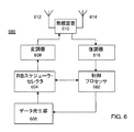
図6はeNodeB500の一部のブロックダイヤグラムであり、ネットワーク10の基地局16、18、20、22、24などと同様な送信ノードの代表的なものであり、上述した方法を実行することによりユーザ端末と通信することができる。図6に描かれた機能ブロックはいろいろな等価な方法で結合されたり再配置されることが理解されよう。そして、機能の多くが1又は複数の適切にプログラムされたデジタル信号処理装置や他の公知の電子回路により実行される。
FIG. 6 is a block diagram of a part of the eNodeB 500, which is a representative transmission node similar to the
eNodeB600は、典型的かつ好都合な適切にプログラムされたデジタル信号処理プロセッサである制御プロセッサ602により動作される。制御プロセッサ602は主としてeNodeB600のいろいろな装置から制御や他の信号を受信したり提供したりする。図6には簡単に、適切なデータ発生装置606からの送信すべきデジタルワードを受信するリソースブロックスケジューラ・セレクタ604と情報を交換する制御プロセッサ602が示されている。
The
スケジューラ・セレクタ604からの情報はOFDM変調器608へ提供され、変調器608により発生された変調信号は、送信アンテナ612を介してユーザ端末へ送信される無線信号を発生する適切な無線装置610へ提供される。ユーザ端末により送信される無線信号は無線装置610や復調器616へ信号を提供する受信アンテナ614により捕捉される。
Information from
当業者は1以上の送信アンテナが備えられることを理解するだろう。制御プロセッサ602が図6に描かれた1又は複数の他の装置を有するように構成されることが理解されるだろう。それはそれらの機能を実行するように構成された専用のプログラムされたプロセッサあるいは他の適切なロジックによって実行できるようにされる。データジェネレータ606、スケジューラ・セレクタ604、変調器608の組み合わせが送信用のダウンリンクサブフレームを発生する。変調器608は情報をOFDM無線装置610へ提供される変調シンボルへ変換し、適切なサブキャリア信号に変調シンボルを印加する。変調されたサブキャリア信号はアンテナ612を介して送信される。
One skilled in the art will appreciate that more than one transmit antenna may be provided. It will be appreciated that the
上述した手順は、例えば送信機と受信機とにより交換される通信信号の時間変動性に応じて必要に応じ繰り返し実行されることが認識されるだろう。 It will be appreciated that the procedure described above is repeatedly performed as necessary depending on, for example, the time variability of the communication signals exchanged between the transmitter and the receiver.
理解を促進するために例えばプログラム可能なコンピュータシステムの要素により実行される動作のシーケンスに関して発明の多くの側面が記述される。いろいろな動作が特別な回路(たとえば、特別な機能を実行するために相互接続されたディスクリートな論理ゲートや特定用途向け集積回路(application−specific integrated circuits))、1又は複数のプロセッサにより実行されるプログラム命令、又はそれらの組み合わせにより実行されることが分かるだろう。この発明が実施される無線トランシーバは例えば、移動電話、ページャー、ヘッドセット、ラップトップコンピュータや他の移動端末、基地局などを含む。 Many aspects of the invention are described in terms of sequences of operations performed, for example, by elements of a programmable computer system to facilitate understanding. Various operations are performed by one or more processors in a special circuit (eg, discrete logic gates or application-specific integrated circuits that are interconnected to perform a special function) It will be understood that it is executed by program instructions or a combination thereof. Wireless transceivers in which the invention is implemented include, for example, mobile phones, pagers, headsets, laptop computers and other mobile terminals, base stations, and the like.
加えて、この発明は、媒体から命令を取ってきてその命令を実行するコンピュータベースのシステム、プロセッサを含むシステムあるいは他のシステムのような命令実行システム、装置、機器によるかあるいはそれらに関連して使用する命令の適切な組が格納される、どのような形式のコンピュータ読み取り可能な記憶媒体中にも完全に具体化されると考えられる。ここで「コンピュータ読み取り可能な媒体」は命令実行システム、装置、機器により使用されるあるいはそれらに関連する、プログラムを含み、格納し、あるいは転送するあらゆる手段であり得る。コンピュータ読み取り可能な媒体は、例えば電子的、磁気的、光学的、電気磁気的、赤外線あるいは半導体システム、装置、機器であり得るが、これに限定されない。さらに具体的なコンピュータ読み取り可能な媒体の例(網羅したリストではない)は、1又は複数のワイヤによる電気的接続、ポータブルコンピュータのディスケット、ランダムアクセスメモリ(RAM)、リードオンリーメモリ(ROM)、書き込み消去可能なメモリ(EPROMやフラッシュメモリ)、光ファイバである。 In addition, the present invention is based on or in connection with an instruction execution system, apparatus, equipment, such as a computer-based system, a system including a processor or other system that takes an instruction from a medium and executes the instruction. It is believed that the invention is fully embodied in any form of computer readable storage medium that stores the appropriate set of instructions to use. As used herein, a “computer-readable medium” may be any means for containing, storing, or transferring a program used by or associated with an instruction execution system, apparatus, or device. The computer readable medium can be, but is not limited to, for example, electronic, magnetic, optical, electromagnetic, infrared, or semiconductor systems, devices, and equipment. More specific examples of computer readable media (not an exhaustive list) are one or more wire electrical connections, portable computer diskettes, random access memory (RAM), read only memory (ROM), writing An erasable memory (EPROM or flash memory) or an optical fiber.
このように本発明は多くの異なった形態で実施されてもよく、全てが上述されているのではなく、そのような全ての形態は発明の範囲内にあることが予想される。本発明のいろいろな側面により、どのような形態も記述された動作を実行するように構成されたロジックあるいは選択的に記述された動作を実行するロジックに及ぶ。 Thus, the present invention may be implemented in many different forms, not all have been described above, and all such forms are expected to be within the scope of the invention. In accordance with various aspects of the present invention, any form extends to logic configured to perform the described operations or logic to perform the selectively described operations.
この出願では、「含む」と「含んでいる」とは、述べられた特徴、整数、ステップあるいは構成要素の存在を明確にすることを強調し、1又は複数の他の特徴、整数、ステップ、構成要素あるいはそのグループが存在あるいは加わることを排除しない。 In this application, “includes” and “including” emphasizes clarifying the existence of the stated feature, integer, step or component, and includes one or more other features, integer, step, Does not exclude the presence or addition of a component or group of components.
上述した特定の実施例は説明のためであり多少なりとも制限的に考えるものではない。発明の範囲は以下の請求項の記載により、請求項の範囲内にある全ての変形や等価なものが発明に含まれる。 The particular embodiments described above are illustrative and not limiting in any way. The scope of the invention is defined by the following claims, and all modifications and equivalents within the scope of the claims are included in the invention.
Claims (15)
ダウンリンク資源割当のための少なくとも一つのパラメータを判定する工程であって、前記少なくとも一つのパラメータはアップリンク帯域幅割当て、アップリンク送信電力、ダウンリンク帯域幅割当て、初期の変調符号化方式の少なくとも一つである工程と、
前記ダウンリンク資源割当を、スケジュールされたダウンリンクのリソースブロックが周波数的にはスケジュールされたアップリンク送信のゼロ周波数±バンド幅の帯域幅内に存在しないように、前記判定された少なくとも一つのパラメータに基づき行う工程とを含むこと特徴とする、
方法。 A method for allocating downlink resources to user terminals in a frequency division duplex communication system,
Determining at least one parameter for downlink resource allocation, wherein the at least one parameter is at least one of uplink bandwidth allocation, uplink transmit power, downlink bandwidth allocation, and initial modulation and coding scheme. One process,
The downlink resource allocation is determined by the at least one parameter determined such that a scheduled downlink resource block does not exist in frequency within the bandwidth of the scheduled uplink transmission zero frequency ± bandwidth. And a process performed based on
Method.
前記ユーザ端末が前記アップリンクにおいて実質的に雑音の制限のあるときは前記ダウンリンク資源割当のための前記少なくとも一つのパラメータが判定されることを特徴とする請求項1に記載の方法。 The user terminal further comprising determining whether there is substantially noise limitation in the uplink;
The method of claim 1, wherein the at least one parameter for the downlink resource allocation is determined when the user terminal is substantially noise limited in the uplink.
ダウンリンク資源割当のための少なくとも一つのパラメータを判定するよう構成された電子プロセッサを有し、
前記少なくとも一つのパラメータはアップリンク帯域幅割当て、アップリンク送信電力、ダウンリンク帯域幅割当て、初期の変調符号化方式の少なくとも一つであり、
前記電子プロッセッサはさらに前記ダウンリンク資源割当を、スケジュールされたダウンリンクのリソースブロックが周波数的にはスケジュールされたアップリンク送信のゼロ周波数±バンド幅の帯域幅内に存在しないように、前記判定された少なくとも一つのパラメータに基づき行うよう構成されていることを特徴とする装置。 An apparatus for downlink resource allocation to user terminals in a frequency division duplex communication system,
An electronic processor configured to determine at least one parameter for downlink resource allocation;
The at least one parameter is at least one of uplink bandwidth allocation, uplink transmission power, downlink bandwidth allocation, and initial modulation and coding scheme;
The electronic processor further determines the downlink resource allocation such that a scheduled downlink resource block does not exist in frequency within the bandwidth of the scheduled uplink transmission zero frequency ± bandwidth. An apparatus configured to perform based on at least one parameter.
前記アップリンクにおいて前記ユーザ端末が実質的に雑音の制限のあるときは前記ダウンリンク資源割当のための前記少なくとも一つのパラメータが判定されることを特徴とする請求項6に記載の装置。 The electronic processor is further configured to determine whether the user terminal is substantially noise limited in the uplink;
7. The apparatus of claim 6, wherein the at least one parameter for the downlink resource allocation is determined when the user terminal is substantially noise limited in the uplink.
ダウンリンク資源割当のための少なくとも一つのパラメータを判定するステップであって、少なくとも一つのパラメータはアップリンク帯域幅割当て、アップリンク送信電力、ダウンリンク帯域幅割当て、初期の変調符号化方式の少なくとも一つであるステップと、
前記ダウンリンク資源割当を行うステップであって、スケジュールされたダウンリンクのリソースブロックが周波数的にはスケジュールされたアップリンク送信のゼロ周波数±バンド幅の帯域幅内に存在しないように、前記判定された少なくとも一つのパラメータに基づいて行うステップと、
を実行させる命令を格納したコンピュータ読み取り可能な記憶媒体。 A computer-readable storage medium storing instructions for causing a computer to execute a method of allocating downlink resources to a user terminal in a frequency division duplex communication system,
Determining at least one parameter for downlink resource allocation, wherein the at least one parameter is at least one of uplink bandwidth allocation, uplink transmit power, downlink bandwidth allocation, and initial modulation and coding scheme. One step,
Performing the downlink resource allocation, wherein the determination is made such that a scheduled downlink resource block does not exist in frequency within a bandwidth of a scheduled uplink transmission zero frequency ± bandwidth. Performing based on at least one parameter;
The computer-readable storage medium which stored the instruction | indication which performs this.
前記アップリンクにおいて実質的に雑音の制限があるときは前記ダウンリンク資源割当のための前記少なくとも一つのパラメータが判定されることを特徴とする請求項12に記載のコンピュータ読み取り可能な記憶媒体。 Further, the user terminal determines whether there is a substantial noise limitation in the uplink;
The computer-readable medium of claim 12, wherein the at least one parameter for the downlink resource allocation is determined when there is substantially noise limitation in the uplink.
Applications Claiming Priority (5)
| Application Number | Priority Date | Filing Date | Title |
|---|---|---|---|
| US22944309P | 2009-07-29 | 2009-07-29 | |
| US61/229,443 | 2009-07-29 | ||
| US12/642,027 | 2009-12-18 | ||
| US12/642,027 US8331254B2 (en) | 2009-07-29 | 2009-12-18 | Interference-aware resource assignment in communication systems |
| PCT/EP2010/060799 WO2011012574A1 (en) | 2009-07-29 | 2010-07-26 | Method, apparatus and computer-readable medium to reduce user equipment self-induced interferences in communication systems |
Publications (2)
| Publication Number | Publication Date |
|---|---|
| JP2013500659A true JP2013500659A (en) | 2013-01-07 |
| JP2013500659A5 JP2013500659A5 (en) | 2013-08-29 |
Family
ID=43526891
Family Applications (1)
| Application Number | Title | Priority Date | Filing Date |
|---|---|---|---|
| JP2012522130A Pending JP2013500659A (en) | 2009-07-29 | 2010-07-26 | Method, apparatus and computer readable recording medium for reducing self-interference at a terminal in a communication system. |
Country Status (4)
| Country | Link |
|---|---|
| US (1) | US8331254B2 (en) |
| EP (1) | EP2460378B1 (en) |
| JP (1) | JP2013500659A (en) |
| WO (1) | WO2011012574A1 (en) |
Cited By (1)
| Publication number | Priority date | Publication date | Assignee | Title |
|---|---|---|---|---|
| WO2017069300A1 (en) * | 2015-10-21 | 2017-04-27 | 엘지전자 주식회사 | Method for controlling self-interference duplication signal for removing self-interference in environment supporting full-duplex radio (fdr) communication, and apparatus therefor |
Families Citing this family (24)
| Publication number | Priority date | Publication date | Assignee | Title |
|---|---|---|---|---|
| US8744384B2 (en) | 2000-07-20 | 2014-06-03 | Blackberry Limited | Tunable microwave devices with auto-adjusting matching circuit |
| US7711337B2 (en) | 2006-01-14 | 2010-05-04 | Paratek Microwave, Inc. | Adaptive impedance matching module (AIMM) control architectures |
| US7714676B2 (en) | 2006-11-08 | 2010-05-11 | Paratek Microwave, Inc. | Adaptive impedance matching apparatus, system and method |
| US7535312B2 (en) | 2006-11-08 | 2009-05-19 | Paratek Microwave, Inc. | Adaptive impedance matching apparatus, system and method with improved dynamic range |
| US7991363B2 (en) | 2007-11-14 | 2011-08-02 | Paratek Microwave, Inc. | Tuning matching circuits for transmitter and receiver bands as a function of transmitter metrics |
| US9026062B2 (en) | 2009-10-10 | 2015-05-05 | Blackberry Limited | Method and apparatus for managing operations of a communication device |
| US8803631B2 (en) | 2010-03-22 | 2014-08-12 | Blackberry Limited | Method and apparatus for adapting a variable impedance network |
| US8860525B2 (en) | 2010-04-20 | 2014-10-14 | Blackberry Limited | Method and apparatus for managing interference in a communication device |
| US8712340B2 (en) | 2011-02-18 | 2014-04-29 | Blackberry Limited | Method and apparatus for radio antenna frequency tuning |
| US8594584B2 (en) | 2011-05-16 | 2013-11-26 | Blackberry Limited | Method and apparatus for tuning a communication device |
| EP2740221B1 (en) | 2011-08-05 | 2019-06-26 | BlackBerry Limited | Method and apparatus for band tuning in a communication device |
| CN102932930B (en) * | 2011-08-10 | 2015-03-18 | 华为技术有限公司 | Resource scheduling method, wireless access equipment and communication system |
| JP5674616B2 (en) * | 2011-09-28 | 2015-02-25 | 京セラ株式会社 | Communication apparatus and communication control method |
| US8948889B2 (en) | 2012-06-01 | 2015-02-03 | Blackberry Limited | Methods and apparatus for tuning circuit components of a communication device |
| US9853363B2 (en) | 2012-07-06 | 2017-12-26 | Blackberry Limited | Methods and apparatus to control mutual coupling between antennas |
| US9350405B2 (en) | 2012-07-19 | 2016-05-24 | Blackberry Limited | Method and apparatus for antenna tuning and power consumption management in a communication device |
| WO2014063342A1 (en) * | 2012-10-26 | 2014-05-01 | Nokia Siemens Networks Oy | Scheduling coordination |
| US10404295B2 (en) | 2012-12-21 | 2019-09-03 | Blackberry Limited | Method and apparatus for adjusting the timing of radio antenna tuning |
| US9374113B2 (en) | 2012-12-21 | 2016-06-21 | Blackberry Limited | Method and apparatus for adjusting the timing of radio antenna tuning |
| KR101413351B1 (en) * | 2013-01-21 | 2014-06-27 | 엘지전자 주식회사 | Method for transmitting uplink signal using reduced number of resource blocks to prevent a deterioration of reference sensitivity in intra non-contiguous carrier aggregation and terminal thereof |
| US9154287B1 (en) | 2013-07-10 | 2015-10-06 | Sprint Communications Company L.P. | Alleviation of time division multiplexing interference between multiple access nodes |
| WO2017043731A1 (en) * | 2015-09-07 | 2017-03-16 | 엘지전자 주식회사 | Method for cancelling self-interference by apparatus that uses fdr scheme |
| US11128433B1 (en) | 2019-10-11 | 2021-09-21 | Sprint Spectrum L.P. | Method and system to facilitate use of conflicting TDD configurations |
| US11510132B2 (en) | 2021-03-17 | 2022-11-22 | Sprint Spectrum L.P. | Use of cell-edge FDD coverage to separate cell-center TDD coverage from adjacent TDD coverage with conflicting TDD configuration |
Family Cites Families (20)
| Publication number | Priority date | Publication date | Assignee | Title |
|---|---|---|---|---|
| US6449267B1 (en) * | 1999-02-24 | 2002-09-10 | Hughes Electronics Corporation | Method and apparatus for medium access control from integrated services packet-switched satellite networks |
| CN103220767B (en) * | 2003-03-26 | 2017-04-12 | 美商内数位科技公司 | Node B, a radio network controller and a method of providing HSDPA services performed thereby |
| MXPA05011262A (en) * | 2003-04-22 | 2006-01-24 | Interdigital Tech Corp | Method and system for integrating resource allocation between time division duplex and frequency division duplex in wireless communication systems. |
| US7133644B2 (en) * | 2003-06-06 | 2006-11-07 | Interdigital Technology Corporation | Digital baseband system and process for compensating for analog radio transmitter impairments |
| US20050118962A1 (en) * | 2003-12-01 | 2005-06-02 | Intel Corporation | Receiver reuse switching |
| EP1730858B1 (en) * | 2004-03-16 | 2009-09-30 | Nokia Corporation | A method, a device and a system for duplex communications |
| DE602006020370D1 (en) * | 2005-06-09 | 2011-04-14 | Ericsson Telefon Ab L M | Power control and Subträgerallokierung depending on the Doppler frequency in an OFDM multiple access system |
| US8396141B2 (en) | 2005-11-29 | 2013-03-12 | Telefonaktiebolaget L M Ericsson (Publ) | Efficient cell selection |
| US20070173260A1 (en) * | 2006-01-23 | 2007-07-26 | Love Robert T | Wireless communication network scheduling |
| WO2007096683A1 (en) | 2006-02-20 | 2007-08-30 | Nokia Corporation | Method and device for preventing interference at a radio receiver device caused by several radio transmitter devices |
| US9949278B2 (en) * | 2006-09-11 | 2018-04-17 | Qualcomm Incorporated | Dynamic power amplifier backoff |
| US8144819B2 (en) | 2007-04-30 | 2012-03-27 | Telefonaktiebolaget L M Ericsson (Publ) | Synchronization for chirp sequences |
| KR101387529B1 (en) * | 2007-10-15 | 2014-04-23 | 엘지전자 주식회사 | Method for communicating data between mobile station and base station, and Mobile communication terminal thereof |
| US8306012B2 (en) * | 2007-11-07 | 2012-11-06 | Telefonaktiebolaget L M Ericsson (Publ) | Channel estimation for synchronized cells in a cellular communication system |
| US7965780B2 (en) * | 2007-12-14 | 2011-06-21 | Telefonaktiebolaget L M Ericsson (Publ) | Determination of pre-coding matrix indicators for spatial multiplexing in a mobile communications system |
| US8295209B2 (en) * | 2008-02-21 | 2012-10-23 | Nokia Corporation | Frame structures with flexible partition boundary for wireless networks |
| KR101440625B1 (en) * | 2008-03-04 | 2014-09-17 | 엘지전자 주식회사 | Method for allocating radio resource in frequency division duplex frame |
| US7897985B2 (en) * | 2008-03-14 | 2011-03-01 | Osram Sylvania | LED light engine kernel and method of making the kernel |
| US9668265B2 (en) * | 2008-03-28 | 2017-05-30 | Qualcomm Inc. | Technique for mitigating interference in a celllar wireless communication netwok |
| US9225481B2 (en) * | 2008-08-11 | 2015-12-29 | Qualcomm Incorporated | Downlink grants in a multicarrier wireless communication system |
-
2009
- 2009-12-18 US US12/642,027 patent/US8331254B2/en active Active
-
2010
- 2010-07-26 EP EP10737318.5A patent/EP2460378B1/en active Active
- 2010-07-26 JP JP2012522130A patent/JP2013500659A/en active Pending
- 2010-07-26 WO PCT/EP2010/060799 patent/WO2011012574A1/en active Application Filing
Cited By (2)
| Publication number | Priority date | Publication date | Assignee | Title |
|---|---|---|---|---|
| WO2017069300A1 (en) * | 2015-10-21 | 2017-04-27 | 엘지전자 주식회사 | Method for controlling self-interference duplication signal for removing self-interference in environment supporting full-duplex radio (fdr) communication, and apparatus therefor |
| US10491260B2 (en) | 2015-10-21 | 2019-11-26 | Lg Electronics Inc. | Method for controlling self-interference duplication signal for removing self-interference in environment supporting full-duplex radio (FDR) communication, and apparatus therefor |
Also Published As
| Publication number | Publication date |
|---|---|
| US20110026415A1 (en) | 2011-02-03 |
| US8331254B2 (en) | 2012-12-11 |
| WO2011012574A1 (en) | 2011-02-03 |
| EP2460378A1 (en) | 2012-06-06 |
| EP2460378B1 (en) | 2014-03-12 |
Similar Documents
| Publication | Publication Date | Title |
|---|---|---|
| JP2013500659A (en) | Method, apparatus and computer readable recording medium for reducing self-interference at a terminal in a communication system. | |
| US11611890B2 (en) | Method and device for handling base sequences in a communications network | |
| US8442069B2 (en) | System and method to enable uplink control for restricted association networks | |
| EP2637374B1 (en) | A method and apparatus for selecting a receiving apparatus for co-channel operation | |
| US9143957B2 (en) | Mitigating cross-device interference | |
| KR101258488B1 (en) | A method and apparatus for signaling to a mobile device which set of training sequence codes to use for a communication link | |
| KR101151030B1 (en) | reverse link traffic power control | |
| KR101101074B1 (en) | Subband scheduling and adjusting power amplifier backoff | |
| US20120106404A1 (en) | Fdd and tdd carrier aggregation | |
| JP2014161073A (en) | Time shifting of co-channel data transmissions to reduce co-channel interference | |
| US20130163501A1 (en) | Flexible cyclic prefix management | |
| Penttinen et al. | LTE‐A Radio Network | |
| TWI444051B (en) | Dynamic power amplifier backoff using headroom information |
Legal Events
| Date | Code | Title | Description |
|---|---|---|---|
| A521 | Request for written amendment filed |
Free format text: JAPANESE INTERMEDIATE CODE: A523 Effective date: 20130712 |
|
| A621 | Written request for application examination |
Free format text: JAPANESE INTERMEDIATE CODE: A621 Effective date: 20130712 |
|
| A977 | Report on retrieval |
Free format text: JAPANESE INTERMEDIATE CODE: A971007 Effective date: 20140305 |
|
| A131 | Notification of reasons for refusal |
Free format text: JAPANESE INTERMEDIATE CODE: A131 Effective date: 20140314 |
|
| A02 | Decision of refusal |
Free format text: JAPANESE INTERMEDIATE CODE: A02 Effective date: 20140926 |